


963
Table of contents
 Loading...
963 Web User Guide
Issue 4

Author: Technical Publications
Issue: 4
Date: 15/01/2009
Part Number: TC200685
Copyright: © 2009 Honeywell Technologies Sàrl, ECC Division. All rights reserved.
This manual contains proprietary information that is protected by copyright. No part of this manual may be
reproduced, transcribed, stored in a retrieval system, translated into any language or computer language, or
transmitted in any form whatsoever without the prior consent of the publisher.
Manufactured for and on behalf of the Environmental and Combustion Controls Division of Honeywell
Technologies Sàrl, Ecublens, La Pièce, 16, 1180 Rolle, Switzerland by its Authorized Representative, Trend Control
Systems Limited.
For information contact:
Trend Control Systems Limited
P.O. Box 34
Horsham
W. Sussex
RH12 2YF
NOTICE: Trend Control Systems Limited makes no representations or warranties of any kind whatsoever with
respect to the contents hereof and specifically disclaims any implied warranties of merchantability or fitness for any
particular purpose. Trend Control Systems Limited shall not be liable for any errors contained herein or for
incidental or consequential damages in connection with the furnishing, performance or use of this material. Trend
Control Systems Limited reserves the right to revise this publication from time to time and make changes in the
content hereof without obligation to notify any person of such revisions or changes.
Windows, Windows XP Professional, Windows XP Home, Windows 2003, Windows 2003, and Windows Vista are
trademarks of Microsoft Corporation. BACnet is a trademark of ASHRAE.
Please send any comments on this or any other Trend technical publication to techpubs@trendcontrols.com

Table of Contents
TABLE OF CONTENTS
1 ABOUT THIS MANUAL................................................................................................................................. 5
1.1 Conventions Used in this Manual ................................................................................................................ 5
1.2 Contacting Trend.......................................................................................................................................... 6
2 ABOUT 963 .......................................................................................................................................................7
3 THE 963 CLIENT DISPLAYS........................................................................................................................ 9
3.1 963 Server Default Page...............................................................................................................................9
3.2 963 Server Start up Page............................................................................................................................ 10
3.3 Alarm Viewer............................................................................................................................................. 11
3.4 Configuration Mode Display...................................................................................................................... 12
3.5 Device Viewer............................................................................................................................................ 13
3.6 Diary Display .............................................................................................................................................17
3.7 Schematic Page Client Display ..................................................................................................................18
3.8 Server Status Page...................................................................................................................................... 19
4 USING 963 FROM A CLIENT......................................................................................................................21
4.1 Basic Use....................................................................................................................................................21
4.1.1 Connect to 963 Server..................................................................................................................... 22
4.1.2 Log In..............................................................................................................................................23
4.1.3 Log Off ...........................................................................................................................................23
4.2 Display a Schematic Page ..........................................................................................................................23
4.3 Adjust Values............................................................................................................................................. 24
4.3.1 Adjust a Knob in a Trend Device.................................................................................................... 24
4.3.2 Adjust a Knob (Analogue Value) in a BACnet Device ..................................................................24
4.3.3 Adjust a Switch in a Trend Device ................................................................................................. 25
4.3.4 Adjust a Switch (Digital Value) in a BACnet Device..................................................................... 25
4.3.5 Adjust a Module Parameter ............................................................................................................26
4.3.6 Relinquish Control of a BACnet Value .......................................................................................... 27
4.4 Alarms........................................................................................................................................................ 27
4.4.1 View Alarms................................................................................................................................... 27
4.4.2 Action Alarms................................................................................................................................. 29
4.4.3 Mute an Alarm Panel ......................................................................................................................30
4.4.4 Run a Manual Alarm Action........................................................................................................... 30
4.4.5 Run Alarm Actions Manually......................................................................................................... 30
4.4.6 Turn Alarm Actions ON/OFF......................................................................................................... 30
4.5 Display Graphs........................................................................................................................................... 31
4.5.1 Display a Compact Graph from a Schematic Page.........................................................................31
4.5.2 Display a Compact Graph from the Device Viewer .......................................................................31
4.5.3 Display a Precision Graph from a Schematic Page......................................................................... 31
4.5.4 Display a Precision Graph from the Device Viewer....................................................................... 32
4.5.5 Display a Chart ...............................................................................................................................32
4.5.6 Load a Graph Definition................................................................................................................. 32
4.5.7 Display the Graph Data................................................................................................................... 33
4.5.8 Zoom in and Out of a Graph........................................................................................................... 33
4.5.9 Formatting Graphs.......................................................................................................................... 33
4.5.10 Display Logged Data ......................................................................................................................33
4.6 Occupation Times ...................................................................................................................................... 34
4.6.1 View Occupation Times .................................................................................................................34
4.6.2 Adjust Occupation Times ...............................................................................................................35
4.7 Playback Recorded Data ............................................................................................................................ 37
4.8 Display the IQ System ...............................................................................................................................38
4.9 Display IQ3 Web Pages .............................................................................................................................38
4.10 Display the 963's Startup Page................................................................................................................... 39
4.11 Enter Configuration Mode on Pre IQ3 Controllers....................................................................................39
4.12 Log Off a Client User.................................................................................................................................39
4.13 Setup Exception Templates........................................................................................................................ 39
4.13.1 Add a Week Set Template .............................................................................................................. 40
4.13.2 Add a Special Day Template .......................................................................................................... 41
4.13.3 Delete a Template........................................................................................................................... 42
4.13.4 Edit a Template............................................................................................................................... 42
4.14 View Server Status..................................................................................................................................... 43
963 Web User Guide TC200685 Issue 4
3

Table of Contents
5 ERROR MESSAGES..................................................................................................................................... 45
INDEX ....................................................................................................................................................................... 47
4
963 Web User Guide TC200685 Issue 4 15/01/2009

About This Manual
1 ABOUT THIS MANUAL
This manual applies to 963 version 3.10. It provides a description of how to use the 963 when accessing the 963
Server from a web browser. It is intended for a reader with no knowledge of the 963 who operates it on a daily basis.
It is assumed that the system has already been set up and engineered to suit user requirements, the user is familiar
with basic computer use, and has knowledge of BMS. It is divided into several sections.
About 963
This section describes 963, and how it works.
The 963 Client Displays
This section explains the different displays presented to the user by 963 when they access 963 using a web
browser.
Using 963 from a Client
This section describes how to use 963 from a web browser once it has been installed and engineered.
After having read and fully understood this manual the user will be familiar with the 963 Supervisor, the
environment in which it operates, making changes to HVAC equipment parameters, coping with incoming alarms,
and all other aspects of using the 963 on a day-to-day basis.
Other relevant documentation is:
963 Data Sheet (TA200636)
963 User Guide (TC200635)
Product Data Sheets
1.1 Conventions Used in this Manual
There are numerous items and instructions in this manual, the conventions below are designed to make it quick and
easy to find and understand the information.
Menu commands are in bold type.
Buttons and options in dialogue boxes that you need to select are in bold type.
The names of text boxes and dialogue boxes are in bold type.
Key combinations that you should press appear in normal type. If joined with a plus sign (+), press and
hold the first key while you press the remaining one(s). For example CTRL+P indicates holding down the
control key while pressing P.
Text you should enter is in Italic type.
963 Web User Guide TC200685 Issue 4
5

About This Manual
1.2 Contacting Trend
Head Office
Trend Control Systems Ltd
PO Box 34
Horsham
Sussex
RH12 2YF
England
Tel: +44 (0) 1403 211888
Fax: +44 (0) 1403 241608
Details of regional offices can be found on our Web site.
Internet
Our company web site (www.trend-controls.com) provides information about our products and us, or our support
web site (http://pnet.trend-controls.com).
Technical Support
Our support department provides technical support during normal office hours. Before contacting them ensure that
you have your Technical Support PIN number available, without this we will be unable to provide you with any
support.
Trend Control Systems Ltd.
Technical Support Department
PO Box 34
Horsham
Sussex
RH12 2YF
England
Tel: +44 (0) 1403 226600
Email: trendts@trendcontrols.com
Fax: +44 (0) 1403 226310
Technical Publications
Please send any comments on this or any other Trend technical publication to techpubs@trendcontrols.com.
6
963 Web User Guide TC200685 Issue 4 15/01/2009

About 963
p
2 ABOUT 963
Once engineered the 963 Supervisor provides the user with a system wide control panel with the facility to monitor
and change the Building Management System (BMS) ensuring that the HVAC equipment operates safely and
efficiently.
The use of colour graphics specially designed for the system displays this information in a simple and effective way.
Graphs and pages of text information can be used to supplement monitored information. A fast and efficient
communications network allows this information to be obtained from HVAC equipment that may be scattered miles
apart in different buildings, on other sites, or even other countries.
It enables the user to monitor HVAC equipment/building services, and make changes to the way the building is
controlled using colour graphics displays. Fault reporting, analysis, and data recording features promote efficient
HVAC equipment operation and effective energy use.
The information and adjustments available to a user can be exactly tailored to that user’s needs. This means that an
operator is never presented with more data or options than he or she requires, thus eliminating a major source of potential
confusion. However, for those whose job function demands it, access can be provided to more detailed information.
When accessed from a web browser, the 963 automatically converts the information into HTML (the language
understood by web browsers) and passes the information to the client machine for display in a web browser when
requested. This means that no additional engineering is required to provide the benefits of the 963 across the
business. Client machines do not require any 963 software to be installed, but must have a connection to a TCP/IP
network, and a web browser installed.
963 server operates in two modes graphic mode and text mode depending on the type of web browser accessing the
server. Graphic mode requires Microsoft Internet Explorer 6 or greater, or Firefox 2, and the SUN JAVA runtime
environment J2SE 5.0 or greater. The browser must have JAVA script enabled. Other browsers are only able to
access the server in text mode. The server can be accessed from web browsers on PCs, PDAs (running Windows
Mobile 2003 Second Edition or greater), Smartphones (running Window Mobile 5 or greater), and the Nokia 9210i
although full client functionality is only available on PCs that meet the requirements for graphic mode. Other
devices are only able to use text mode.
The table below list the features that are available to a client.
Feature Notes
Schematic Pages In graphics mode any page may be displayed, however there may be some slight
differences in the appearance of the page. WMF and EMF format graphics are not
supported. Both dynamic and static objects as well as the backdrop will be displayed. In
text mode graphics are not displayed, the page is reproduced as 3 tables containing live
data (dynamic objects), actions, and static objects. In both modes static objects, which
erform unsupported actions are not displayed. Active content such as Excel files is not
supported on the client.
963 Actions The following actions are supported CONFIG, DROPALLLINES*, EXECUTESMS*,
GOTO, GOTO Diary
MESSAGE
VIEWGRAPH
*
Graphic mode only.
*
, PLAY*, POPUP*, SEND, SENDAUTO*, SETGENERIC*,
*
*
, GOTO NEXT*, GOTO PREVIOUS*, LOGINAS, LOGOUT,
, VIEWPOINTS*, VIEWQUERY, WEB.
The EXECUTESMS action is only available if the SMS Direct option has been licensed.
Adjustment of values Fully supported.
Display of graphs Fully supported. When in text mode a table of the graph’s values is displayed.
Movement between pages Fully supported.
Access to device
Fully supported.
configuration mode
Viewing/acknowledgement
of alarm
Adjustment of controller
Fully supported in graphic mode only. Only the GOTO, MESSAGE, PLAY, and WEB
actions are available for use with viewing/acknowledging alarms in a web browser.
Fully supported.
occupation times
System security Fully supported.
Device Viewer Only allows viewing of information plus the facility to adjust values, graph values, and
enter configuration mode on device that support configuration mode. It is not possible to
learn the system. Graphic mode only.
Note that 963 has not been tested with all devices and Trend cannot guarantee a particular device’s compatibility
with 963 server.
963 Web User Guide TC200685 Issue 4
7

About 963
This page is intentionally left blank.
8
963 Web User Guide TC200685 Issue 4 15/01/2009

The 963 Client Displays
3 THE 963 CLIENT DISPLAYS
3.1 963 Server Default Page
The 963 Servers Default Page shown below is displayed when you connect to the 963 from a client. It enables you
to log in.
963 Web User Guide TC200685 Issue 4
9

The 963 Client Displays
3.2 963 Server Start up Page
The 963 Start up Page shown below is displayed once you have logged in. It provides access to the Schematic
Page Client Display, Device Viewer, Diary Display and if you are authorised to view alarms contains the Alarm
Viewer.
Note that for users that only have access to schematics the Schematics Page Display will be shown instead.
10
963 Web User Guide TC200685 Issue 4 15/01/2009
The 963 Client Displays
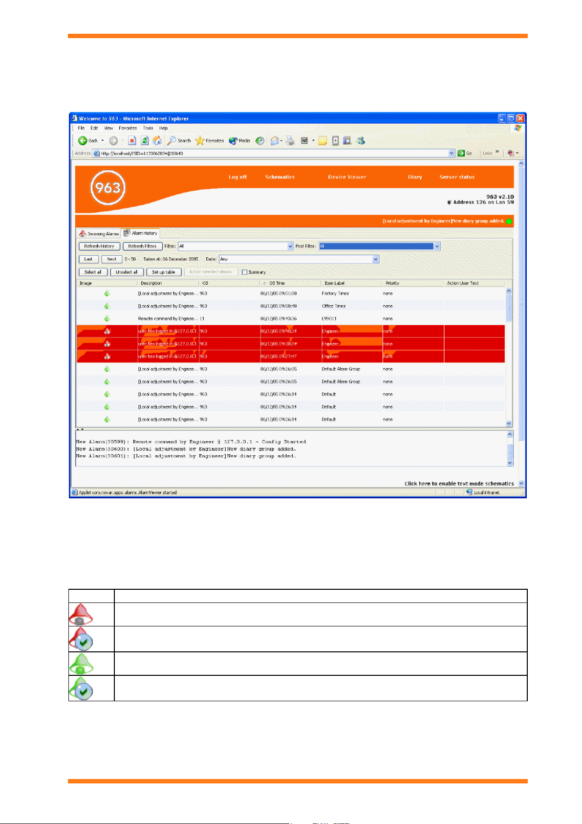
3.3 Alarm Viewer
The Alarm Viewer is only available when accessed from a web browser that supports the 963’s graphic mode. It is
displayed on the 963 Servers Start up Page providing you have authority to view alarms. It displays the alarms that
have been received. These alarms can be filtered to reduce the amount of data displayed.
The Alarm Viewer has two tabs:
Alarm History
Incoming alarms
Colours are used to indicate whether the alarm is a set alarm or a cleared alarm. A red bell indicates a set alarm, and
a green bell indicates a cleared alarm. If the alarm has been actioned by the user, a bell will appear with a tick over
it. The table below shows the different icons.
Icon Description
Set alarm that has not been actioned.
Set alarm that has been actioned.
Cleared alarm that has not been actioned.
Cleared alarm that has been actioned.
The Alarm History is colour coded to indicate whether the alarm is current. Red indicates that the alarm is current.
963 Web User Guide TC200685 Issue 4
11

The 963 Client Displays
Alarm History tab
The Alarm History stores all the alarms after they have been processed. This list stores the all the alarms in the
database that have been processed whether or not they have been actioned by the user. The alarms can be viewed in
chronological order or a summary view.
Summary View - This gives a count for each alarm type for each point.
Chronological View - a systematic alarm history sorted by time order.
Incoming Alarms tab
The Incoming Alarms contains the last 100 alarms to be received as they arrive. New alarms appear at the top of
the list when they are first received.
3.4 Configuration Mode Display
The Configuration Mode Display, shown below, allows access to configuration mode on a specified IQ System device. It allows simple adjustments to be made to the strategy. When in configuration mode all the screen prompts originate from the controller and all keyboard inputs are sent to the controller when Submit is clicked.
12
963 Web User Guide TC200685 Issue 4 15/01/2009

The 963 Client Displays
3.5 Device Viewer
The Device Viewer is only available when accessed from a web browser that supports the 963’s graphic mode. It enables inputs, outputs, adjustments, time zones, and critical alarms from the selected part of the system to be displayed, and for values to be adjusted, or graphed. E.g. if the internetwork is selected, all values from the internetwork are displayed. If a particular Lan is selected only values from that Lan are displayed.
The Device Viewer is divided into two different areas:
Data Display
Navigator
Data Display
The Data Display contains the requested modules, it is colour coded to indicate whether the alarm is current. Red
indicates that the alarm is current. Once the values have been displayed it is possible to adjust values, display a
graph, or enter the configuration mode of IQ System devices that support configuration mode. The display contains
a number of columns that display the values of the inputs, outputs, adjustments, time zones, and critical alarms from
the part of the system selected in the Navigator.
963 Web User Guide TC200685 Issue 4
13

The 963 Client Displays
Column Description
Icon Contains an icon that indicates the module type.
Sensor Modules
Digital Input Modules
Virtual Sensor Modules
Critical Alarm Modules
Knob Modules
Switch Modules
Time zone Modules
Analogue Driver Modules
Digital Driver Modules
Plot Modules
These icons may also overlayed with icons indicating the modules alarm state, and whether it can be
adjusted.
Module in alarm but alarm has been acknowledged
Module in alarm
Module value can be adjusted.
Module value cannot be adjusted.
There is a graph available for the module.
Label The module label. For plot modules from pre IQ3 controllers will display the label of the module whose
value the plot module is recording.
Value The current value of the module.
Units The value’s engineering units.
Error
Description
A description of any error that exists for the value.
Alarm
The alarm code for the alarm if the module is in an alarm condition.
Code
Item A code indicating the module type and number (e.g. S1 specifies Sensor module number 1)
S Sensor Modules
I Digital Input Modules
W Switch Modules
Z Time zone Modules
K Knob Modules
D All Driver modules for IQ system sites, Analogue Driver Modules for BACnet sites
J Digital Driver Modules for BACnet sites
X Virtual Sensor Modules
P Plot Module
M Critical Alarm Modules
LAN The Lan number of the controller containing the module
OS The network address of the controller containing the module
Tele The phone number or IP address used to address the site containing the module.
Pin Level The PIN level required to adjust the value.
14
963 Web User Guide TC200685 Issue 4 15/01/2009

The 963 Client Displays
The display also contains a number of buttons that enable the types of modules displayed to be selected.
Icon What is Displayed
Sensors
Digital Inputs
Virtual sensors (calculated MKT values)
Critical Alarms
Knobs
Switches
Time Zones
Analogue Driver
Digital Driver
Plots
Refreshes the values.
This causes 963 to only display items of the selected item types whose label matches the search string.
Inputs
Adjustments
Drivers
Plots
Select/deselects all inputs
Select/deselects all adjustments
Select/deselects all drivers
Select/deselects plots
Navigator
The Navigator displays a tree view of the system to which 963 is connected, enabling the level at which the system
is displayed in the Data Display to be selected. For example, clicking a Lan will display all the points with labels on
that Lan. Access to this display can be restricted to certain users. Icons indicate the type of object. The table below
lists the different icons.
Icon
Description
Supervisors
921 Supervisor
940 Supervisor
942 Supervisor
943 Supervisor
945 Supervisor
950 Supervisor
963 Supervisor, 962 Supervisor, S2 Supervisor, or ViewPoint
NDP
IQView
Devices
ANC
963 Web User Guide TC200685 Issue 4
15
Loading...