

Page 1
USER’S GUIDE
CRS4Fxxxx-10x
Slide-in-Module Media
Converter
RS485/422 Copper to Fiber
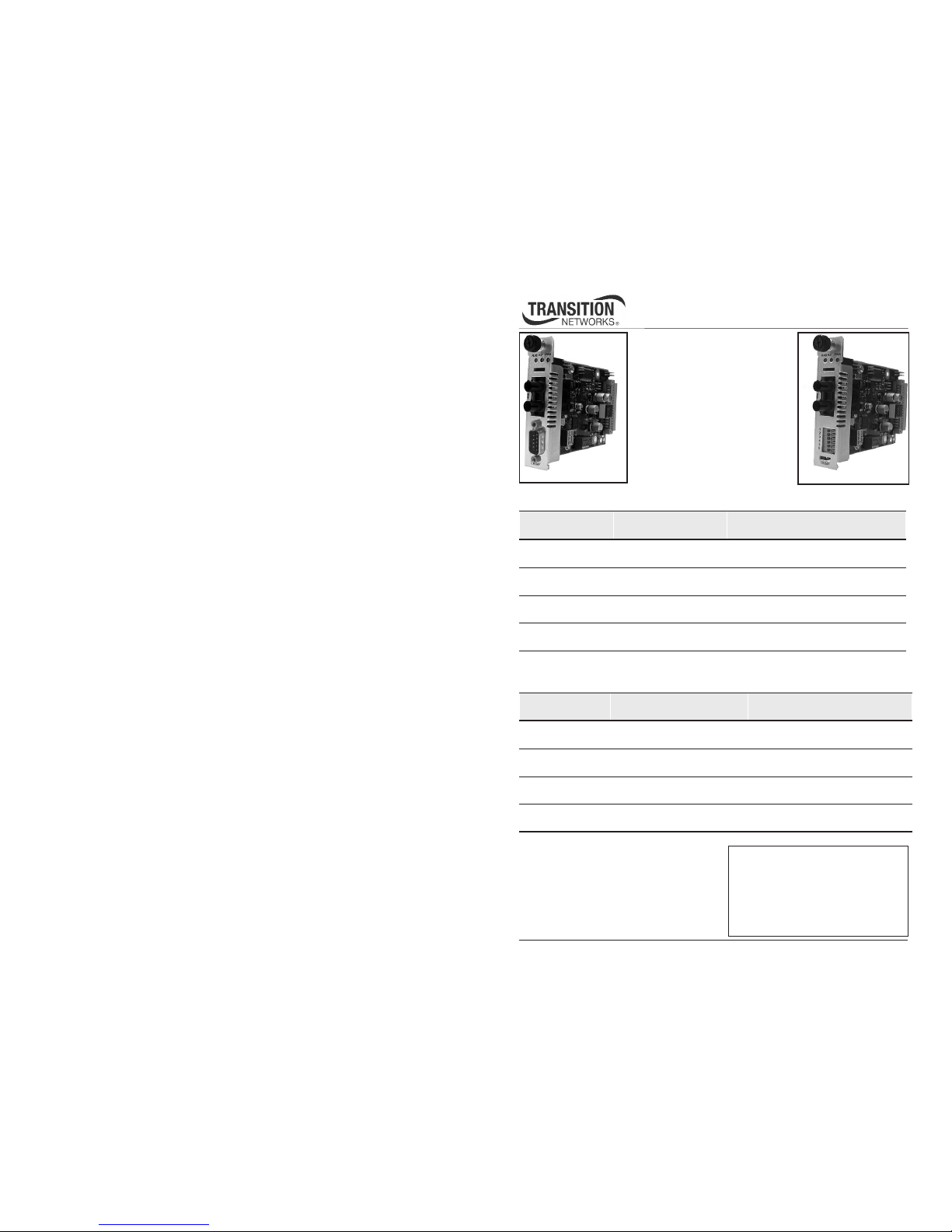
Transition Networks CRS4Fxxxx10x series media converters are
designed to be installed in the
PointSystem™ chassis and connect
RS485/422 copper cable to fiberoptic cable at asynchronous data
rates up to 1.25 Mb/s.
The CRS4F31xx-10x media converters use a male DB-9 port for the copper link:
The CRS4F32xx-10x media converters use a 6-position terminal block for the copper
link:
* Maximum cable distance is 1200m (4000 ft)
@ <90 kb/s decreasing logarithmically to
92m (300 ft) @ 500 kb/s.
**Typical maximum cable distance. Actual
distance is dependent upon the physical
characteristics of the network installation.
Installation . . . . . . . . . . . . . . . . . . . . .3
Operation . . . . . . . . . . . . . . . . . . . . .8
Cable Specifications . . . . . . . . . . . . . .9
Technical Specifications . . . . . . . . . .12
Troubleshooting . . . . . . . . . . . . . . .13
Contact Us . . . . . . . . . . . . . . . . . . .14
Compliance Information . . . . . . . . .15
Part Number Port One - Copper
DB-9 port
Port Two - Fiber-Optic
CRS4F3111-100
RS485/422
1200 m (4000 ft)*
ST, 1300 nm multimode
2 km (1.2 miles)**
CRS4F3113-100
RS485/422
1200 m (4000 ft)*
SC, 1300 nm multimode
2 km (1.2 miles)**
CRS4F3114-100
RS485/422
1200 m (4000 ft)*
SC, 1310 nm single mode
20 km (12.4 miles)**
CRS4F3115-100
RS485/422
1200 m (4000 ft)*
SC, 1310 nm single mode
40 km (24.8 miles)**
Part Number Port One - Copper
6-position terminal block
Port Two - Fiber-Optic
CRS4F3211-100
RS485/422
1200 m (4000 ft)*
ST, 1300 nm multimode
2 km (1.2 miles)**
CRS4F3213-100
RS485/422
1200 m (4000 ft)*
SC, 1300 nm multimode
2 km (1.2 miles)**
CRS4F3214-100
RS485/422
1200 m (4000 ft)*
SC, 1310 nm single mode
20 km (12.4 miles)**
CRS4F3215-100
RS485/422
1200 m (4000 ft)*
SC, 1310 nm single mode
40 km (24.8 miles)**
CRS4F31xx-10x
CRS4F32xx-10x
Page 2
2
Tech Support: 1-800-260-1312 International: 00-1-952-941-7600 (24 hours)
CRS4Fxxxx-10x
Part Number Part One - Copper
DB-9 Port
Port Two - Fiber Optic
CRS4F3129-100
RS485
1200 m (4000 ft)*
SC, 1310TX/1550RX nm, single mode
20 km (12.4 miles)**
CRS4F3129-101
RS485
1200 m (4000 ft)*
SC, 1550TX/1310RX nm, single mode
20 km (12.4 miles)**
CRS4F3129-102
RS485
1200 m (4000 ft)*
SC, 1310TX/1550RX nm, single mode
40 km (24.8 miles)**
CRS4F3129-103
RS485
1200 m (4000 ft)*
SC, 1550TX/1310RX nm, single mode
40 km (24.8 miles)**
Part Number Part One - Copper -6-
position terminal block
Port Two - Fiber Optic
CRS4F3229-100
RS485
1200 m (4000 ft)*
SC, 1310TX/1550RX nm, single mode
20 km (12.4 miles)**
CRS4F3229-101
RS485
1200 m (4000 ft)*
SC, 1550TX/1310RX nm, single mode
20 km (12.4 miles)**
CRS4F3229-102
RS485
1200 m (4000 ft)*
SC, 1310TX/1550RX nm, single mode
40 km (24.8 miles)**
CRS4F3229-103
RS485
1200 m (4000 ft)*
SC, 1550TX/1310RX nm, single mode
40 km (24.8 miles)**
The CRS4F3129-10x media converters use a male DB-9 port for the copper link:
The CRS4F32xx-10x media converters use a 6-position terminal block for the copper link:
* Maximum cable distance is 1200m (4000 ft) @ <90 kb/s decreasing logarithmically to
92m (300 ft) @ 500 kb/s.
**Typical maximum cable distance. Actual distance is dependent upon the physical
characteristics of the network installation.
techsupport@transition.com -- Click the “Transition Now” link for a live Web chat.
3
Installation
CAUTION: Wear a grounding device and observe electrostatic discharge precautions
when setting the switches. Failure to observe this caution could result in damage to,
and subsequent failure of, the media converter.
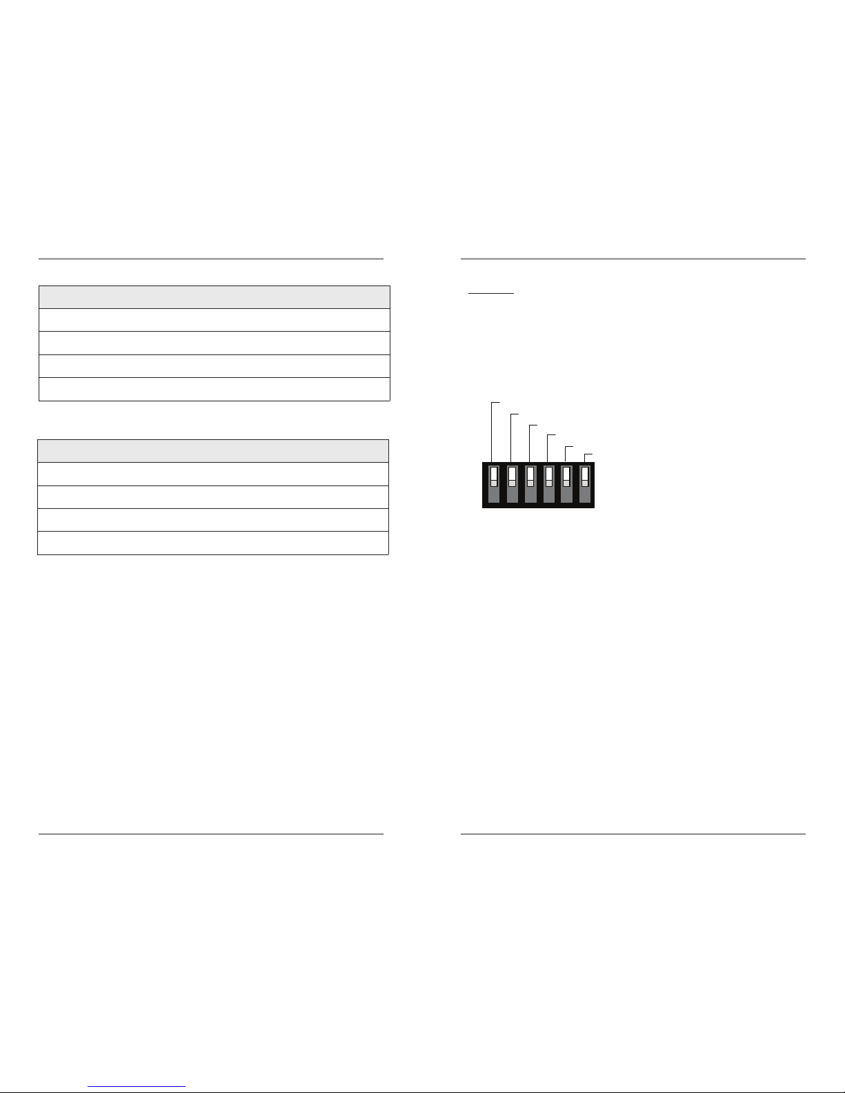
Set the 6-Position Switch
The 6-position switch is located on the side of the media converter. Use a small flatblade screwdriver or a similar device to set the recessed switches. Refer to the
drawing for the locations of the six individual switches.
Switch 1 - 130 ohm resistor on “receive”
up = Disable
down = Enable (Switch 5 must also be set to “4-wire” (down)
When enabled, switch 1 inserts a 130 ohm resistor on the wire pair:
• Receive (-) (B) RS485 4-wire, receive (-) RS422
• Receive (+) (A) RS485 4-wire, receive (+) RS422
Switch 2 - 130 ohm resistor on “transmit”
up = Disable
down = Enable. (Switch 5 must also be set to “2-wire” (up)
When enabled, switch 2 inserts a 130 ohm resistor on the wire pair:
• Transmit/Receive (-) (B) RS485 2-wire, transmit (-) RS422
• Transmit/Receive (+) (A) RS485 2-wire, transmit (+) RS422
Switch 3 - 1K ohm “pull-down”
up = Disable
down = Enable. (Switch 5 must also be set to “2-wire” (up)
When enabled, switch 3 enables a 1K ohm pull-down on the wire:
• Transmit/Receive (-) (B) RS485 2-wire, transmit (+) RS422
130 Ohm Resistor on Receive
1K Ohm Pull-Down
1K Ohm Pull-Up
2-Wire/4Wire
RS485/RS422
130 Ohm Resistor on Transmit
123456
Page 3
4
Tech Support: 1-800-260-1312 International: 00-1-952-941-7600 (24 hours)
CRS4Fxxxx-10x
Installation -- Continued
Switch 4 - 1K ohm “pull-up”
up = Disable
down = Enable (Switch 5 must also be set to “2-wire” (up)
When enabled, switch 4 enables a 1K ohm pull-up on the wire:
• Transmit/Receive (+) (A) RS485 2-wire, transmit (+) RS422
Switch 5 - 2-wire/4-wire
up = 2-wire
down = 4-wire
Set switch 5 to 2-wire (up) to enable the wire pair:
• Transmit/Receive (-) (B) RS485 2-wire, transmit (-) RS422
• Transmit/Receive (+) (A) RS485 2-wire, transmit (+) RS422
for RS422 2-wire, half-duplex operation
Set switch 5 to 4-wire (down) to enable the wire pair:
• Receive (-) (B) RS485 4-wire, transmit (-) RS422
• Receive (+) (A) RS485 4-wire, transmit (+) RS422
for RS422 4-wire, full-duplex operation
Switch 6 - RS485 / RS422
up = RS485
down = RS422
Set switch 6 to RS485 (up) to prevent echo in the 2-wire mode.
Set switch 6 to RS422 (down) to allow “transmit only” for the wire pair:
• Transmit/Receive (-) (B) RS485 2-wire, transmit (-) RS422
• Transmit/Receive (+) (A) RS485 2-wire, transmit (+) RS422
techsupport@transition.com -- Click the “Transition Now” link for a live Web chat.
5
Installation -- Continued
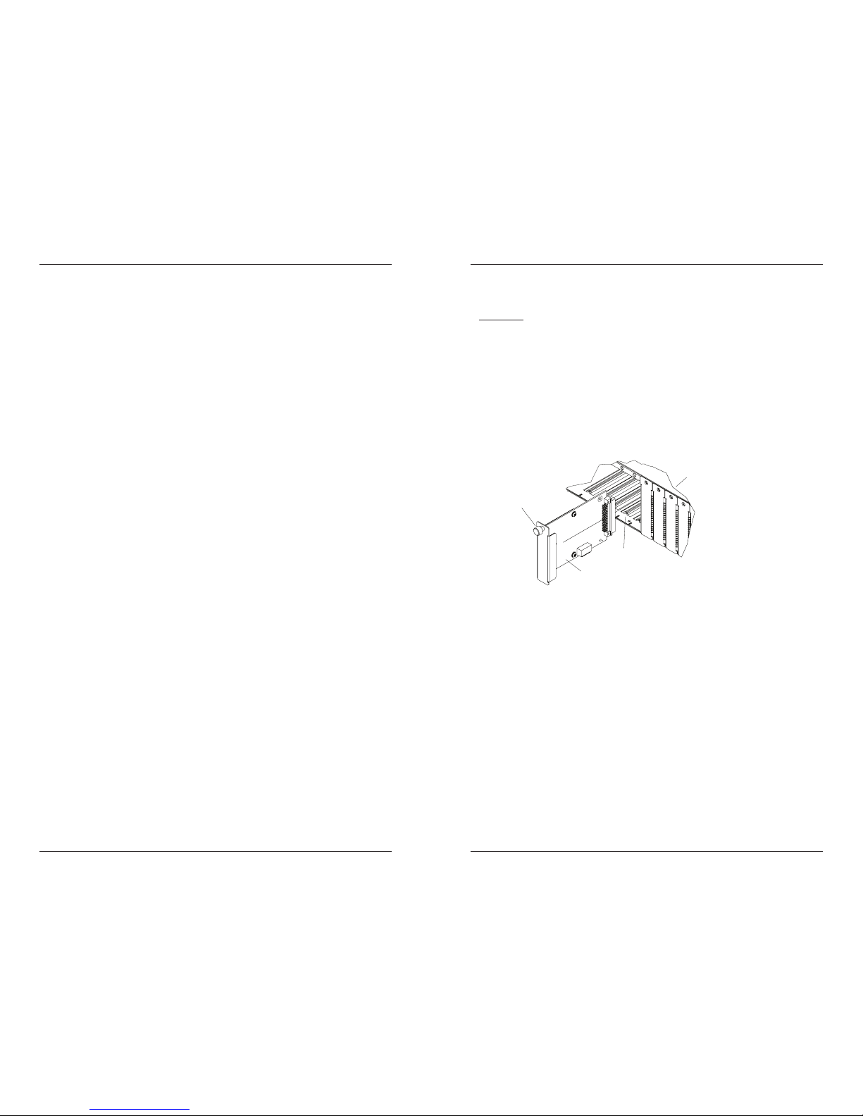
Install the Slide-In-Module
CAUTION: Wear a grounding device and observe electrostatic discharge precautions
when installing the media converter. Failure to observe this caution could result in
damage to, and subsequent failure of, the media converter.
To install the CRS4Fxxxx-10x media converter slide-in-module:
1. Locate an empty installation slot on the PointSystem™ Chassis.
2. Carefully slide the slide-in-module into the installation slot, aligning the
module with the installation guides.
3. Ensure that the module is firmly seated inside the chassis.
4. Push in and rotate the attached panel fastener screw to secure the module to the
chassis front.
Install the Fiber Cable
1. Locate or build fiber cable with male, two-stranded TX to RX connectors
installed at both ends.
2. Connect the fiber cables to the CRS4Fxxxx-10x media converter as described:
• Connect the male TX cable connector the female TX port.
• Connect the male RX cable connector to the female RX port.
3. Connect the fiber cables to the other device (another media converter, hub,
etc.) as described:
• Connect the male TX cable connector the female RX port.
• Connect the male RX cable connector to the female TX port.
Media Converter
Point System Chassis
Panel Fastener
Slot
Page 4

6
Tech Support: 1-800-260-1312 International: 00-1-952-941-7600 (24 hours)
CRS4Fxxxx-10x
Install the Fiber Cable
1. Locate or build fiber cable with male, two-stranded TX to RX connectors
installed at both ends.
2. Connect the fiber cables to the CRS4Fxxxx-100 media converter as described:
• Connect the male TX cable connector the female TX port.
• Connect the male RX cable connector to the female RX port.
3. Connect the fiber cables to the other device (another media converter, hub,
etc.) as described:
• Connect the male TX cable connector the female RX port.
• Connect the male RX cable connector to the female TX port.
Connect fiber cable
to media converter
as shown.
Connect fiber cable
to other device
(media converter,
hub, etc.) as shown
RX
TX
RX
TX
techsupport@transition.com -- Click the “Transition Now” link for a live Web chat.
7
Installation -- Continued
Install the Copper Cable (DB-9 port)
Install the copper cable as instructed if the media converter has a
DB-9 copper port (CRS4F31xx-10x models).
Note: Shielded RS485/422 cables are required for EMC
compliance.
1. Locate or build RS485/422 cables with a female DB-9
connector on one end and a DB-9 connector that is
compatible with the other device on the other end of the
cable.
2. Connect the female DB-9 connector at one end of cable to the
male DB-9 port on the CRS4F31xx-10x media converter.
3. Connect the DB-9 connector at the other end of the cable to the DB-9 port on
the other device.
Power the Media Converter
The media converter is powered through the PointSystem™ chassis.
Install the Copper Cable (6-position terminal block)
Install the copper cable as instructed if the media converter
has a 6-position terminal block (CRS4F32xx-100 models).
NOTE: Shielded RS485/422 cables are required for EMC
compliance.
1. Locate or build RS485/422 cables with the six
individual wires stripped at both ends.
2. Insert the individual wires at one end of cable into the
six terminal block ports on the CRS4F32xx-10x media
converter.
3. Insert the individual wires at the other end of the cable
into the six terminal block ports on the other device,
matching the same color of cable with the number of the
port.
DB-9
1
2
3
4
5
6
Page 5

8
Tech Support: 1-800-260-1312 International: 00-1-952-941-7600 (24 hours)
CRS4Fxxxx-10x
Operation
After installation, the media converter should function without operator
intervention. Use the status LEDs to monitor the media converter operation in the
network.
PWR On The media converter is connected to external power.
RXF On A link has been established with the fiber link.
RXC On Data has been received on the copper link.
Flashing Data is transferring on the copper link.
CRS4F31xx-100 CRS4F32xx-100
9
-
B
D
rebiF
CRS4F32
RXC RXF PWR
TX RX
9
-
B
D
rebiF
CRS4F31
RXC RXF PWR
TX RX
SNMP
Use SNMP at an attached terminal or at a remote location to monitor the media
converter by monitoring:
• Local fiber link status
• Receive data activity on the copper link
• Local switch settings
(Network commands cannot be entered via SNMP.)
See the on-line documentation that comes with Transition Networks FocalPoint™
software for applicable commands and usage on-line at:
www.transition.com
techsupport@transition.com -- Click the “Transition Now” link for a live Web chat.
9
Cable Specifications
RS485/422 Copper Cable
Maximum Data Rate: 1.25 Mb/s
Gauge: 24 to 22 AWG
Maximum Cable Distance: 1200m (4000 ft) @ <90 kb/s
decreasing logarithmically to:
92m (300 ft) @ 500 kb/s
Not
Used
5
4
3
2
1
9
8
7
6
Signal Ground
Receive (-) (B) RS485 4-wire, (-) RS422
Receive (+) (A) RS485 4-wire, (+) RS422
Transmit/Receive (+) (A) RS485 2 or 4-wire, (+) RS422
Transmit/Receive (-) (B) RS485 2 or 4-wire, (-) RS422
DB-9 Port:
1
2
3
4
5
6
Signal Ground
Receive (-) (B) RS485 4-wire, (-) RS422
Receive (+) (A) RS485 4-wire, (+) RS422
Transmit/Receive (+) (A) RS485 2 or 4-wire, (+) RS422
Transmit/Receive (-) (B) RS485 2 or 4-wire, (-) RS422
6-Position Terminal Block:
Signal Ground
Page 6

10
Tech Support: 1-800-260-1312 International: 00-1-952-941-7600 (24 hours)
CRS4Fxxxx-10x
Cable Specifications -- Continued
Fiber Cable
Bit Error Rate: <10-9
Single mode fiber (recommended): 9 µm
Multimode fiber (recommended): 62.5/125 µm
Multimode fiber (optional): 100/140, 85/140, 50/125 µm
CRS4F3111-100 1300 nm multimode
Fiber Optic Transmitter Power: min: -19.0 dBm max: -14.0 dBm
Fiber Optic Receiver Sensitivity: min: -30.0 dBm max: -14.0 dBm
Link Budget: 11.0 dB
CRS4F3113-100 1300 nm multimode
Fiber Optic Transmitter Power: min: -19.0 dBm max: -14.0 dBm
Fiber Optic Receiver Sensitivity: min: -30.0 dBm max: -14.0 dBm
Link Budget: 11.0 dB
CRS4F3114-100 1310 nm single mode
Fiber-optic Transmitter Power: min: -15.0 dBm max: -8.0 dBm
Fiber-optic Receiver Sensitivity: min: -31.0 dBm max: -8.0 dBm
Link Budget: 16.0 dB
CRS4F3115-100 1310 nm single mode
Fiber-optic Transmitter Power: min: -8.0 dBm max: -2.0 dBm
Fiber-optic Receiver Sensitivity: min: -34.0 dBm max: -7.0 dBm
Link Budget: 26.0 dB
CRS4F3211-100 1300 nm multimode
Fiber Optic Transmitter Power: min: -19.0 dBm max: -14.0 dBm
Fiber Optic Receiver Sensitivity: min: -30.0 dBm max: -14.0 dBm
Link Budget: 11.0 dB
CRS4F3213-100 1300 nm multimode
Fiber Optic Transmitter Power: min: -19.0 dBm max: -14.0 dBm
Fiber Optic Receiver Sensitivity: min: -30.0 dBm max: -14.0 dBm
Link Budget: 11.0 dB
CRS4F3214-100 1310 nm single mode
Fiber-optic Transmitter Power: min: -15.0 dBm max: -8.0 dBm
Fiber-optic Receiver Sensitivity: min: -31.0 dBm max: -8.0 dBm
Link Budget: 16.0 dB
CRS4F3215-100 1310 nm single mode
Fiber-optic Transmitter Power: min: -8.0 dBm max: -2.0 dBm
Fiber-optic Receiver Sensitivity: min: -34.0 dBm max: -7.0 dBm
Link Budget: 26.0 dB
The fiber optic transmitters on this device meet Class I Laser safety requirements
per IEC-825/CDRH standards and comply with 21 CFR1040.10 and
21CFR1040.11.
techsupport@transition.com -- Click the “Transition Now” link for a live Web chat.
11
Cable Specifications -- Continued
Fiber Cable
CRS4F3129-100 1310TX/1550TR nm single mode
CRS4F3129-101 1550TX/1310TR nm single mode
Fiber Optic Transmitter Power: min: -13.0 dBm max: -6.0 dBm
Fiber Optic Receiver Sensitivity: min: -32.0 dBm max: -3.0 dBm
Link Budget: 19.0 dB
CRS4F3129-102 1310TX/1550TR nm single mode
CRS4F3129-103 1550TX/1310TR nm single mode
Fiber Optic Transmitter Power: min: -8.0 dBm max: -3.0 dBm
Fiber Optic Receiver Sensitivity: min: -33.0 dBm max: -3.0 dBm
Link Budget: 25.0 dB
CRS4F3229-100 1310TX/1550TR nm single mode
CRS4F3229-101 1550TX/1310TR nm single mode
Fiber Optic Transmitter Power: min: -13.0 dBm max: -6.0 dBm
Fiber Optic Receiver Sensitivity: min: -32.0 dBm max: -3.0 dBm
Link Budget: 19.0 dB
CRS4F3229-102 1310TX/1550TR nm single mode
CRS4F3229-103 1550TX/1310TR nm single mode
Fiber Optic Transmitter Power: min: -8.0 dBm max: -3.0 dBm
Fiber Optic Receiver Sensitivity: min: -33.0 dBm max: -3.0 dBm
Link Budget: 25.0 dB
Page 7

12
Tech Support: 1-800-260-1312 International: 00-1-952-941-7600 (24 hours)
CRS4Fxxxx-10x
Technical Specifications
For use with Transition Networks Model CRS4Fxxxx-10x or equivalent
Data Rate 0 to 1.25 Mb/s
Dimensions 3.4" x 5.0" x 0.86" (86 mm x 127 mm x 22 mm)
Shipping Weight 3 oz. (91 g) approximately
Power Consumption 5 Watts
MTBF 250,000 hours (MIL-HDBK-217F)
687,500 hours (Bellcore7 V5.0)
Environment
Operating Temp: 0 to 50°C (32° to 122° F )
Storage Temp: -40° to 85°C (-40° to 185°F)
Humidity: 5 to 95%, non condensing
Warranty Lifetime
*Manufacturer’s rated ambient temperature. Tmra range for this slide-in-module
depends on the physical characteristics and the installation configuration of the
Transition Networks PointSystem chassis in which this slide-in-module will be
installed.
The information in this user’s guide is subject to change. For the most up-to-date
information on the CRS4Fxxxx-10x media converter, view the user’s guide on-line at:
www.transition.com
Note: The stand-alone version of the media converter is SRS4Fxxxx-10x. For more
information, see the SRS4Fxxxx-10x user guide on-line at:
www.transition.com.
WARNING: Visible and invisible laser radiation when open. Do not stare into the
beam or view the beam directly with optical instruments. Failure to observe this
warning could result in an eye injury or blindness.
WARNING: Use of controls, adjustments or the performance of procedures other than
those specified herein may result in hazardous radiation exposure.
CAUTION: Copper based media ports, e.g., Twisted Pair (TP) Ethernet, USB, RS232,
RS422, RS485, DS1, DS3, Video Coax, etc., are intended to be connected to intrabuilding (inside plant) link segments that are not subject to lightening transients or
power faults. Copper based media ports, e.g., Twisted Pair (TP) Ethernet, USB,
RS232, RS422, RS485, DS1, DS3, Video Coax, etc., are NOT to be connected to interbuilding (outside plant) link segments that are subject to lightening transients or power
faults. Failure to observe this caution could result in damage to equipment.
techsupport@transition.com -- Click the “Transition Now” link for a live Web chat.
13
Troubleshooting
If the media converter fails, isolate and correct the failure by determining the answers
to the following questions and then taking the indicated action:
1. Is the PWR (Power) LED on the media converter illuminated?
NO
• Is the media converter inserted properly into the chassis?
• Is the power cord properly installed in the chassis and in the grounded AC
outlet?
• Does the grounded AC outlet provide power?
• Contact Technical Support: US/Canada: 1-800-260-1312, International:
00-1-952-941-7600.
YES
• Proceed to step 2.
2. Is the RXC LED illuminated when data is sent across the
RS485/422 copper link?
NO
• Check the RS485/422 copper cable for proper connection.
• Contact Technical Support: US/Canada: 1-800-260-1312, International:
00-1-952-941-7600.
YES
• Proceed to step 3.
3. Is the RXF (fiber link) LED illuminated?
NO
• Disconnect and reconnect the fiber cables to restart the initialization
process.
• Verify that the TX and RX cables on the media converter are connected to
the RX and TX ports, respectively, on the other media converter.
• Contact Technical Support: US/Canada: 1-800-260-1312, International:
00-1-952-941-7600.
YES
• Proceed to step 4.
4. Does the data fail to move across the link, even though both RXC and
RXF LEDs are illuminated?
YES
• Check switches 5 and 6 for proper configuration and check the RS485/422
cables for proper connection.
• Contact Technical Support: US/Canada: 1-800-260-1312, International:
00-1-952-941-7600.
NO
• Contact Technical Support: US/Canada: 1-800-260-1312, International:
00-1-952-941-7600.
Page 8

14
Tech Support: 1-800-260-1312 International: 00-1-952-941-7600 (24 hours)
CRS4Fxxxx-10x
Contact Us
Technical Support
Technical support is available 24 hours a day.
US and Canada: 1-800-260-1312
International: 00-1-952-941-7600
Transition Now
Chat live via the Web with Transition Networks Technical Support.
Log onto
www.transition.com and click the Transition Now link.
Web-Based Seminars
Transition Networks provides seminars via live web-based training.
Log onto
www.transition.com and click the Learning Center link.
E-Mail
Ask a question anytime by sending an e-mail to our technical support staff.
techsupport@transition.com
Address
Transition Networks
10900 Red Circle Drive
Minnetonka, MN 55343, U.S.A.
telephone: 952-941-7600
toll free: 800-526-9267
fax: 952-941-2322
Declaration of Conformity
Name of Mfg: Transition Networks
10900 Red Circle Drive, Minneatonka MN 55343 U.S.A.
Model: CRS4Fxxxx-10x Series Media Converter
Part Number: CRS4F3111-100, CRS4F3113-100, CRS4F3114-100,
CRS4F3115-100, CRS4F3211-100, CRS4F3213-100,
CRS4F3214-100, CRS4F3215-100, CRS4F3129-100,
CRS4F3129-101, CRS4F3129-102, CRS4F3129-103,
CRS4F3229-100, CRS4F3229-101, CRS4F3229-102,
CRS4F3229-103
Regulation: EMC Directive 89/336/EEC
Purpose: To declare that the CRS4Fxxxx-10x to which this declaration refers is in
conformity with the following standards.
EMC Directive 2004/108/EC; EN 55022:2006+A1:2007 Class A;
EN55024:1998+A1:2001+A2:2003; EN61000-3-2; EN61000-3-3; CFR Title 47 Part 15
Subpart B Class A; Low Voltage Directive: 2006/95/EC; CFR Title 21 Section 1040.10
Class I
I, the undersigned, hereby declare that the equipment specified above conforms to
the above Directive(s) and Standard(s).
August 2010
Stephen Anderson, Vice-President of Engineering Date
techsupport@transition.com -- Click the “Transition Now” link for a live Web chat.
15
Compliance Information
CISPR22/EN55022 Class A + EN55024
CE Mark
FCC Regulations
This equipment has been tested and found to comply with the limits for a Class A digital device,
pursuant to part 15 of the FCC rules. These limits are designed to provide reasonable protection
against harmful interference when the equipment is operated in a commercial environment. This
equipment generates, uses, and can radiate radio frequency energy and, if not installed and used in
accordance with the instruction manual, may cause harmful interference to radio communications.
Operation of this equipment in a residential area is likely to cause harmful interference, in which
case the user will be required to correct the interference at the user's own expense.
Canadian Regulations
This digital apparatus does not exceed the Class A limits for radio noise for digital apparatus set
out on the radio interference regulations of the Canadian Department of Communications.
Le présent appareil numérique n'émet pas de bruits radioélectriques dépassant les limites applicables
aux appareils numériques de la Class A prescrites dans le Règlement sur le brouillage
radioélectrique édicté par le ministère des Communications du Canada.
European Regulations
Warning
This is a Class A product. In a domestic environment this product may cause radio interference in
which case the user may be required to take adequate measures.
Achtung !
Dieses ist ein Gerät der Funkstörgrenzwertklasse A. In Wohnbereichen können bei Betrieb dieses
Gerätes Rundfunkstörungen auftreten. In diesem Fäll ist der Benutzer für Gegenmaßnahmen
verantwortlich.
Attention !
Ceci est un produit de Classe A. Dans un environment domestique, ce produit risque de créer des
interférences radioélectriques, il appartiendra alors à l'utilsateur de prende les measures spécifiques
appropriées.
CAUTION: RJ connectors are NOT INTENDED FOR CONNECTION TO THE
PUBLIC TELEPHONE NETWORK. Failure to observe this caution could result in
damage to the public telephone network.
Der Anschluss dieses Gerätes an ein öffentlickes Telekommunikationsnetz in den EGMitgliedstaaten verstösst gegen die jeweligen einzelstaatlichen Gesetze zur Anwendung der
Richtlinie 91/263/EWG zur Angleichung der Rechtsvorschriften der Mitgliedstaaten über
Telekommunikationsendeinrichtungen einschliesslich der gegenseitigen Anerkennung ihrer
Konformität.
In accordance with European Union Directive 2002/96/EC of the European
Parliament and of the Council of 27 January 2003, Transition Networks will accept
post usage returns of this product for proper disposal. The contact information for this
activity can be found in the 'Contact Us' portion of this document.
Page 9

Trademark Notice
All trademarks and registered trademarks are the property of their respective owners.
Copyright Restrictions
© 2004-2010 Transition Networks.
All rights reserved. No part of this work may be reproduced or used in any form or by any means graphic, electronic, or mechanical - without written permission from Transition Networks.
Printed in the U.S.A.
33280.E
16
CRS4Fxxxx-10x
 Loading...