

User’s Guide
l
CPSMP-200
AC Power Supply Module
• PointSystem™
• CPSMC18xx-xxx Accessory
• CPSMC19xx-100 Accessory
The Transition Networks CPSMP-200 power supply is a slide-in-module that
provides optional, redundant AC power to the CPSMC18xx-xxx and the
CPSMC19xx-100 PointSystem™ chassis.
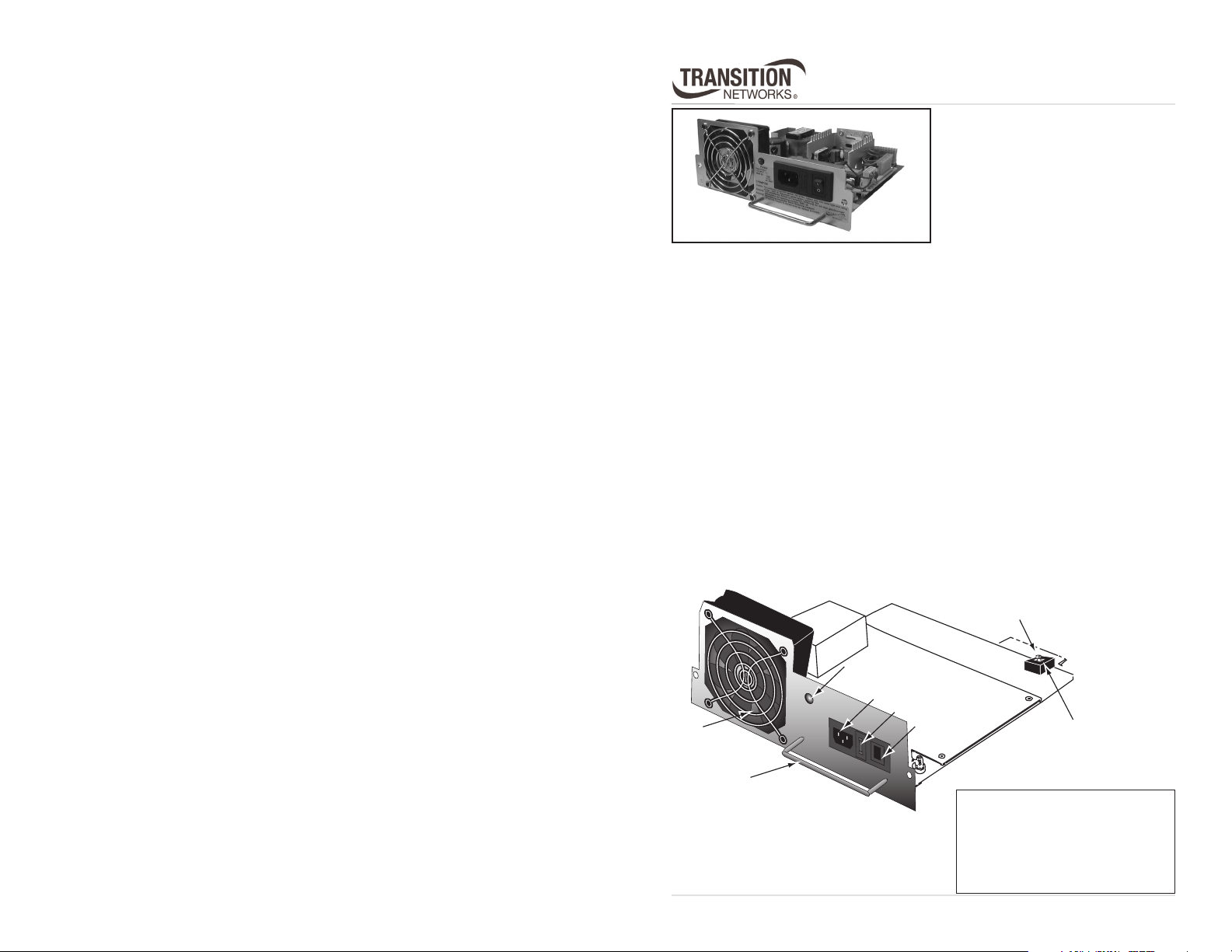
The figure below illustrates the components of the CPSMP-200 power supply:
•A power LED indicator.
• An AC power connector that supplies power from an AC wall outlet.
•A fuse installed in a fuse holder.
• An On/Off switch that, when set to “I”, allows the module to supply
power to the PointSystem™ chassis.
•A Primary/Secondary switch that allows the module to be configured as
the “primary” or as the “secondary” power supply.
•A Management/Manual switch that allows the PointSystem™ software to
control and override the physical setting of the Primary/Secondary switch.
•A fan to cool the interior of the PointSystem™ chassis.
•A handle for installing and removing the power supply module.
Primary/Secondary
Switch
Power LED
AC Power Connector
Fuse Holder
Fan
Handle
I
0
On/Off Switch
Management/Manua
Switch
Installation . . . . . . . . . . . . . . . .2
Maintenance . . . . . . . . . . . . . . .6
Technical Specifications . . . . . .9
Troubleshooting . . . . . . . . . . .10
Contact Us . . . . . . . . . . . . . . .11
Compliance Information . . . . .12
CPSMP-200
t
t
CAUTION: Wear a grounding device and observe electrostatic discharge
precautions when installing or servicing the power supply module. Failure to
observe this caution could result in damage to, and subsequent failure of, the
power supply module.
Installation
The CPSMP-200 AC power supply module may replace an existing AC
module, or it may be installed as the redundant power supply module in
either an AC-powered or a DC-powered PointSystem™ chassis.
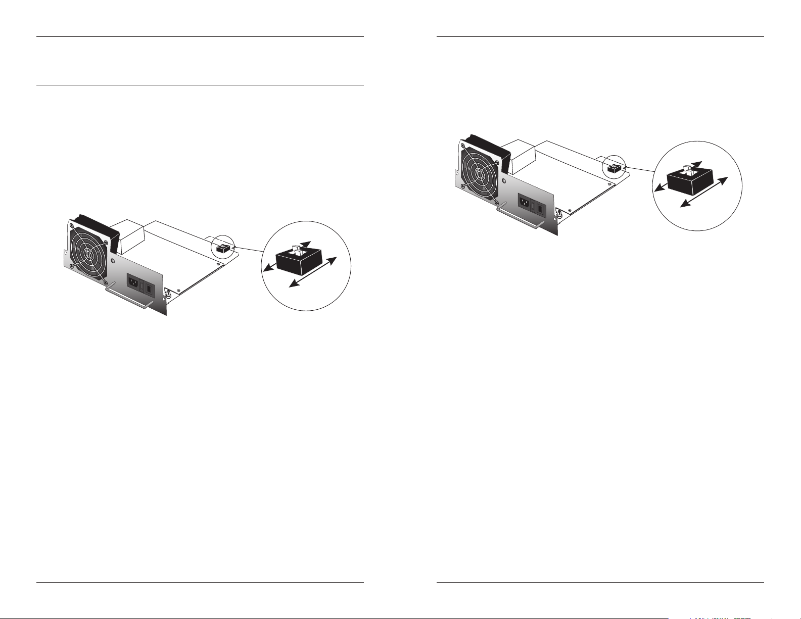
Switch Settings
The CPSMP-200 power supply module has a set of Primary/SecondaryManagement/Manual switches installed on the circuit board.
Primary
Managemen
Primary/Secondary Switch
The Primary/Secondary switch allows the module to be configured as the
‘Primary’ or as the ‘Secondary’ power supply.
• As the ‘Primary’ power supply, it provides power to the entire chassis.
• As the ‘Secondary’ power supply, it waits in stand-by mode, ready to
supply power to the chassis in the event of power failure from the
‘Primary’ power supply.
Primary
Managemen
I
0
Secondary
Manual
I
0
Secondary
Manual
Management/Manual Switch
The Management/Manual switch allows the PointSystem™ software to control
and override the physical setting on the Primary/Secondary switch.
• When set to ‘Management’, the power supply module has the default
configuration of ‘Primary’, unless changed at the software interface to
‘Secondary’.
• When set to ‘Manual’, the power supply module has the configuration as
set by the Primary/Secondary switch. The software interface cannot
change the setting.
Configuring Two Power Supply Modules
• For load sharing, where each module supplies power to half the chassis,
set both power supply modules to ‘Primary’.
• For back-up power supply, set one power supply module to ‘Primary’
(which supplies power to the entire chassis) and the other to ‘Secondary’.
In this mode, the secondary module is in stand-by mode and takes over
in the event of a power failure of the primary module.
NOTE: At least one power supply module must be set to ‘Primary.’ If
both modules are set to ‘Secondary,’ neither will supply power to the
chassis.
Tech Support: 1-800-260-1312 -- International: 00-1-952-941-7600 -- (24 hours)
2
techsupport@transition.com -- Click the “Transition Now” link for a live Web chat.
3
CPSMP-200
WARNING: Do not connect the power supply module to the external power
source before installing it into the chassis. Failure to observe this caution could
result in equipment damage and/or personal injury or death.
Install the CPSMP-200
NOTE: The CPSMP-200 power supply module may be “hot swapped” (i.e.,
installed in the chassis while the chassis is in operation) provided the module
to be installed has been disconnected from its external power source and the
module’s On/Off switch has been set to “0”.
To install the CPSMP-200 as the redundant power supply module into either
the CPSMC18xx-xxx or the CPSMC19xx-100 PointSystem™ chassis:
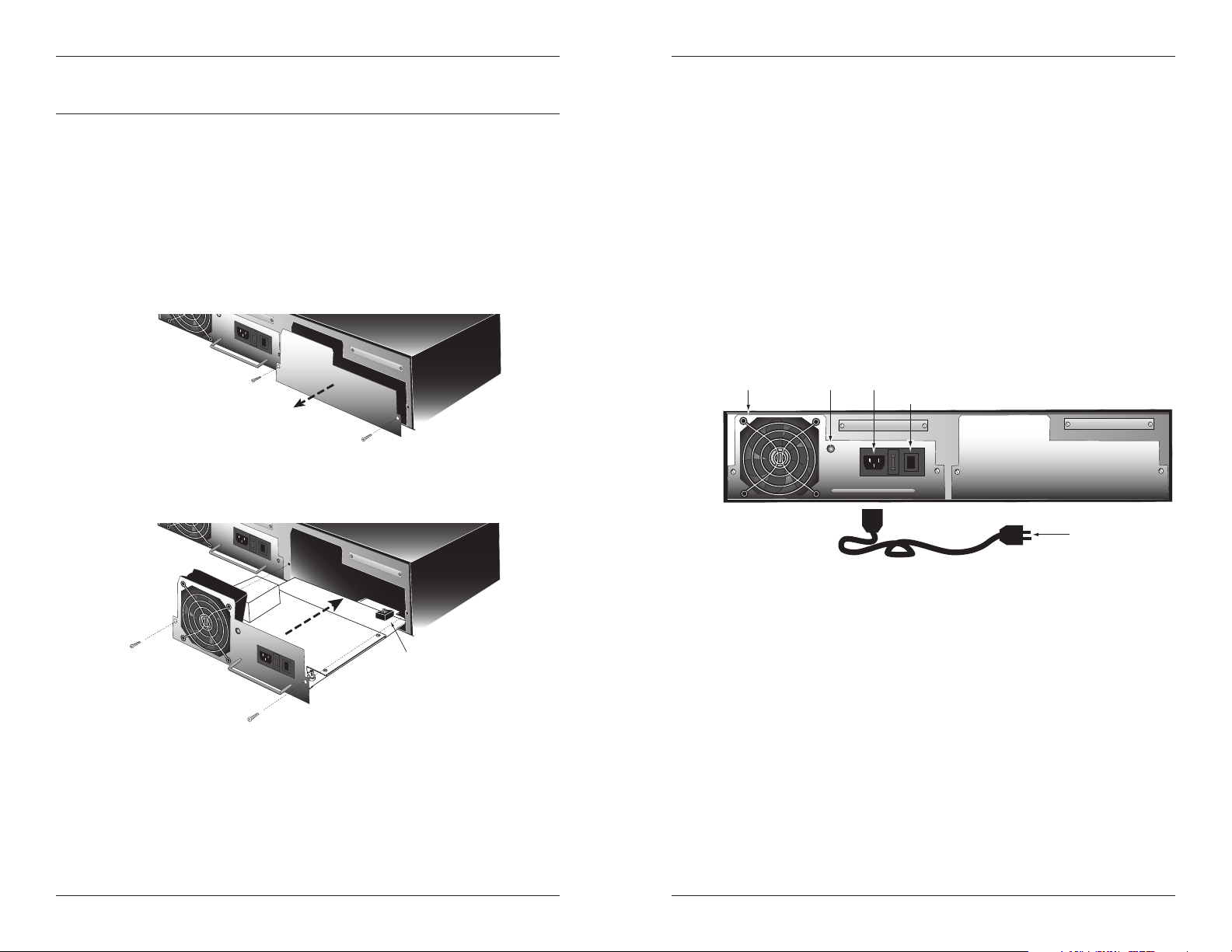
1. Remove and retain the two (2) screws that secure the protective plate to
the rear of the chassis and pull the plate away from the chassis.
I
0
2. Set the On/Off switch on the power supply module to “0”.
3. Set the Primary/Secondary switch and the Management/Manual switch, if
necessary (see page 3.)
I
0
Connect to External Power
CAUTION: Ensure that the On/Off switch on the power supply module is
set to “0” when connecting to the external power source. Failure to observe
this caution could result in damage to, and subsequent failure of, the power
supply module.
To connect the CPSMP-200 to external power:
1. Set the On/Off switch on the power supply module to “0”.
2. Connect the female end of the AC power cord to the male end of the AC
power connector.
3. Connect the male end of the AC power cord into the correct voltage AC
rack or wall socket.
4. Set the On/Off switch on the power supply module to “I”.
5. Verify that the CPSMP-200 power supply module is powered by
observing the fan and the illuminated power LED.
Fan Power LED AC Power Connector
On/Off Switch
I
0
AC Power Cord
I
0
Primary/Secondary Switch
and
Management/Manual Switch
4. Carefully slide the power supply module into the installation slot,
aligning the module with the installation guides. Ensure that the power
supply module is firmly seated against the chassis backplane.
5. Carefully install the two (2) screws (retained in step 1) through the power
supply module and into the chassis. Rotate the screws clockwise to
secure.
Tech Support: 1-800-260-1312 -- International: 00-1-952-941-7600 -- (24 hours)
4
techsupport@transition.com -- Click the “Transition Now” link for a live Web chat.
5

CPSMP-200
WARNING: Do not connect the power supply module to the external power
source before installing it into the chassis. Failure to observe this caution could
result in equipment damage and/or personal injury or death.
Maintenance
Replace the CPSMP-200
NOTE: The CPSMP-200 power supply module may be “hot swapped” (i.e.,
replaced while the chassis is in operation) provided the module to be
replaced has been disconnected from its external power source and the
module’s On/Off switch has been set to “0”.
On/Off Switch
5. Set the Primary/Secondary switch and the Management/Manual switch on
the replacement power supply module, if necessary (see page 3).
I
0
I
0
Primary/Secondary Switch
and
Management/Manual Switch
I
0
AC Power Cord
To replace the CPSMP-200 power supply module:
1. Ensure the On/Off switch on the power supply module is set to “0”.
2. Disconnect the AC power cord from the AC power source.
3. Remove the two (2) screws that secure the power supply module to the
chassis. Retain the screws for installing the replacement module.
4. Carefully slide the power supply module out of the chassis.
I
0
I
0
6. Carefully slide the replacement power supply module into the installation
slot, aligning the module with the installation guides.
7. Ensure that the power supply module is firmly seated inside the chassis.
8. Carefully install the two (2) retained screws through the power supply
module into the chassis, rotating clockwise to secure.
9. See the “Connect to External Power” section (page 5) for instructions on
re-connecting the power supply module to the external power source.
Tech Support: 1-800-260-1312 -- International: 00-1-952-941-7600 -- (24 hours)
6
techsupport@transition.com -- Click the “Transition Now” link for a live Web chat.
7

CPSMP-200
Replace the Fuse
CAUTION: Ensure that the power supply module has been disconnected
from the external power source and the module’s On/Off switch has been
set to “0”. Failure to observe this caution could result in damage to, and
subsequent failure of, the power supply module.
NOTE: The CPSMP-200 power supply module may be “hot swapped” (i.e.,
serviced while the chassis is in operation) provided the module to be serviced
has been disconnected from its external power supply and the module’s
On/Off switch has been set to “0”.
To replace the fuse in the CPSMP-200 power supply module:
1. Ensure the On/Off switch on the power supply module is set to “0”.
2. Disconnect the AC power cord from the external power source.
3. From the inside edge of the power receptacle, insert a small flat blade
screwdriver into the groove on the front, inside edge of the fuse holder
and carefully pry the fuse holder from the power supply module.
On/Off Switch
I
0
Fuse Holder
Technical Specification
For use with Transition Networks Model CPSMP-200 or equivalent.
Standards UL Listed EN60950; FCC & CISPR Class A&B;
EN61000-3-2 Class D; CE Mark
Dimensions 8.3" x 8.4" x 2.7" (211 mm x 211 mm x 69 mm)
Weight 1 lb. (0.45 kg) approximately
Power Input 100-240 V, 47/63Hz, 0.62-1.5 Amp,
(typical with a fully-loaded chassis)
Voltage Tolerance ± 10%
Low-Line Input Current 3.3A max.
Inrush Current 40A max.( peak starting current) @ high line
Transient Recovery Time 1ms max.
Power Output 12VDC at 10.83 Amp max.
Power Factor >
Fuse 4 Amp/250 V
MTBF 60,000 hours (MIL217F2 V5.0) (MIL-HDBK-217F)
Environment Tmra*: 0 to 60°C (32 to 140°F )
Warranty Lifetime
*Manufacturer’s rated ambient temperature: Tmra range for this power supply
module depends on the physical characteristics and the installation configuration
of the Transition Networks PointSystem™ chassis in which this module will be
installed.
0.95 (no inductive or capacitive distinction)
248,000 hours (Bellcore7 V5.0)
Storage Temperature: -20 to 85°C (-4 to 185°F)
Humidity: 5 to 95%, non condensing
Altitude: 0 to 10,000 feet
Fuse
4. Carefully remove the fuse from the fuse holder.
5. Install a same size and rating replacement fuse in the fuse holder.
6. Return the fuse holder and fuse to the installation position in the power
supply module. Snap the fuse holder into place.
7. See the “Connect to External Power” section (page 5) for instructions on
re-connecting the power supply module to the external power source.
Tech Support: 1-800-260-1312 -- International: 00-1-952-941-7600 -- (24 hours)
8
techsupport@transition.com -- Click the “Transition Now” link for a live Web chat.
9

CPSMP-200
Troubleshooting
If the power supply module fails, isolate and correct the failure by determining
the answers to the following questions and then taking the indicated action:
1. Is the Power LED on the CPSMP-200 power supply module
illuminated?
NO
• Is the power supply module inserted properly into the chassis?
• Is the power supply module properly connected to the external
power source?
• Does the external power source provide power?
• Contact Technical Support: US/Canada: 1-800-260-1312,
International: 00-1-952-941-7600.
YES
• Proceed to step 2.
2. Is the fuse on the CPSMP-200 power supply intact?
NO
• CAUTION: See the “Replace the Fuse” section (page 8) for the
proper method for replacing the fuse to the power supply module.
• Contact Technical Support: US/Canada: 1-800-260-1312,
International: 00-1-952-941-7600.
YES
• Contact Technical Support: US/Canada: 1-800-260-1312,
International: 00-1-952-941-7600.
Contact Us
Technical Support
Technical support is available 24 hours a day.
US and Canada: 1-800-260-1312
International: 00-1-952-941-7600
Transition Now
Chat live via the Web with Transition Networks Technical Support.
Log onto www.transition.com and click the Transition Now link.
Web-Based Seminars
Transition Networks provides seminars via live web-based training.
Log onto www.transition.com and click the Learning Center link.
E-Mail
Ask a question anytime by sending an e-mail to our technical support staff.
techsupport@transition.com
Address
Transition Networks; 6475 City West Parkway; Minneapolis, MN 55344, USA
telephone: 952-941-7600; toll free: 800-526-9267; fax: 952-941-2322
Tech Support: 1-800-260-1312 -- International: 00-1-952-941-7600 -- (24 hours)
10
Declaration of Conformity
Name of Mfg: Transition Networks
Model: CPSMP-200 Redundant Power Supply 120/240 VAC
Part Number(s): CPSMP-200
Regulation: EMC Directive 89/336/EEC
Purpose: To declare that the
conformity with the following standards.
CISPR 22:1997+A1:2000; EN 55022:1998 + A1:2000 Class A&B; EN 55024:1998;
FCC Part 15 Subpart B; EN61000-3-2:1995+A14:2000; EN61000-3-3:1995
I, the undersigned, hereby declare that the equipment specified above conforms to the above
Directive(s) and Standard(s).
Stephen Anderson, Vice-President of Engineering Date
techsupport@transition.com -- Click the “Transition Now” link for a live Web chat.
6475 City West Parkway, Minneapolis MN 55344 USA
CPSMP-200
to which this declaration refers is in
_July 8, 2000_____
11

Compliance Information
CISPR22/EN55022 Class A & B, EN61000-3-2 Class D, EN61000-3-3
CE Mark
FCC Regulations
This equipment has been tested and found to comply with the limits for a Class A&B digital
device, pursuant to part 15 of the FCC rules. These limits are designed to provide
reasonable protection against harmful interference when the equipment is operated in a
commercial environment. This equipment generates, uses, and can radiate radio frequency
energy and, if not installed and used in accordance with the instruction manual, may cause
harmful interference to radio communications. Operation of this equipment in a residential
area is likely to cause harmful interference, in which case the user will be required to correct
the interference at the user's own expense.
Canadian Regulations
This digital apparatus does not exceed the Class A&B limits for radio noise for digital
apparatus set out on the radio interference regulations of the Canadian Department of
Communications.
Le présent appareil numérique n'émet pas de bruits radioélectriques dépassant les limites
applicables aux appareils numériques de la Class A&B prescrites dans le Règlement sur le
brouillage radioélectrique édicté par le ministère des Communications du Canada.
Trademark Notice
All trademarks and registered trademarks are the property of their respective owners.
Copyright Restrictions
© 2000, 2004-2005 Transition Networks.
All rights reserved. No part of this work may be reproduced or used in any form or by any
means - graphic, electronic, or mechanical - without written permission from Transition
Networks.
Printed in the U.S.A.
33186.D
 Loading...