

User’s Guide
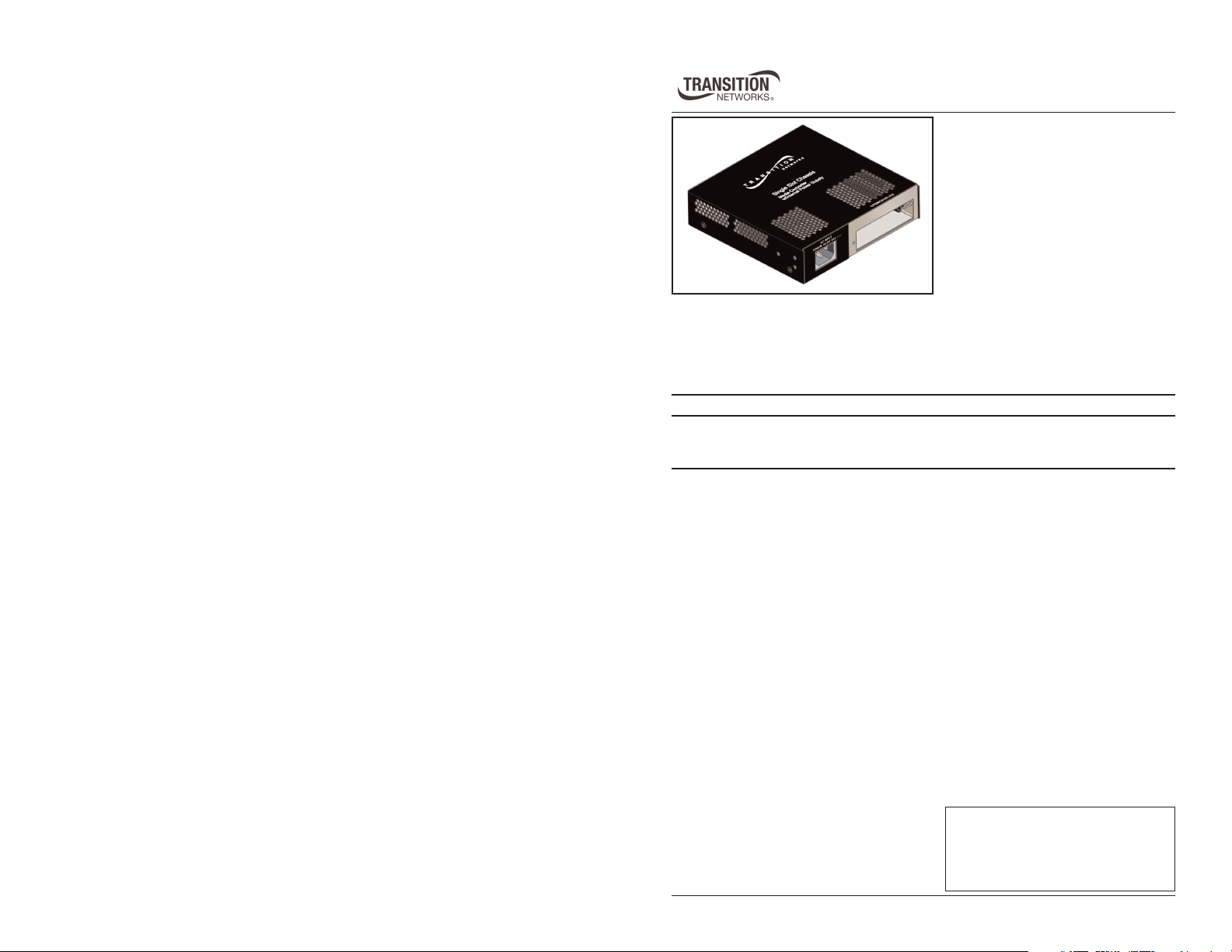
CPSMC0100-210
Single-Slot PointSystem™ Chassis
with Internal Power Supply
The Transition Networks CPSMC0100-210 single-slot PointSystem™ chassis is
equipped with an internal power supply, and is designed for installation of a single,
selectable Transition Networks PointSystem™ slide-in-module media converter
with a maximum of 12 Watts.
Part Number Description
CPSMC0100-210 Single-slot PointSystem™ chassis, with an internal power
supply, intended for installation of any PointSystem™ slidein-module media converter up to 12 Watts.
Note: The following media converter families are not compatible with Transition
Networks CPSMC0100-210 single-slot PointSystem™ chassis: C4TEF,
CAPTF, CBFTF-120, CBFTF-140, CEMTF, CGFEG and the CMEFG.
Installation . . . . . . . . . . . . . . . . . .2
Technical Specifications . . . . . . . .5
Troubleshooting . . . . . . . . . . . . . .6
Contact Us . . . . . . . . . . . . . . . . . .7
Compliance Information . . . . . . . .8
CPSMC0100-210
r
Installation
Installing a Slide-in-Module
CAUTION: Wear a grounding device and observe electrostatic discharge
precautions when installing the media converter slide-in-module into the
single-slot chassis. Failure to observe this caution could result in damage to,
and subsequent failure of, the slide-in-module media converter.
Note: The maximum power capacity for the chassis slot is 12 Watts.
Note: The CPSMC0100-210 chassis is rated as “Class B” only when Class B
compliant slide-in-module media converters are installed. The chassis
will drop to a “Class A“ rating whenever a Class A slide-in-module
media converter is installed.
To install a slide-in-module into the single-slot chassis:
1. Refer to the user’s guide that comes with the slide-in-module to ensure
that any switches or jumpers on the slide-in-module circuit board are set
correctly for the site installation.
2. Carefully align the slide-in-module with the chassis installation guides
and slide the module into the installation slot.
3. Ensure that the slide-in-module is firmly seated inside the chassis.
4. Push in and rotate the attached panel faster screw clockwise to secure the
slide-in-module to the chassis.
Installation -- Continued
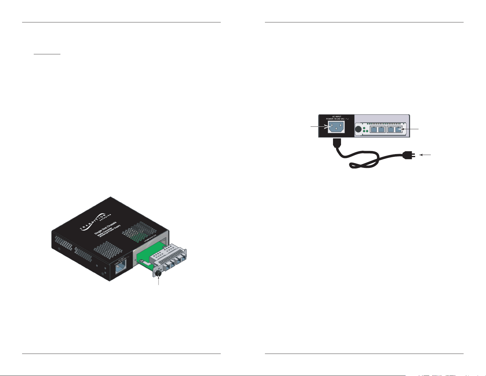
Powering the Chassis
The single-slot chassis automatically powers on when connected to an AC
outlet supplying 100-240 VAC. To power on the single-slot chassis:
1. Connect the female end of the power cord to the AC power connector on
the front panel of the chassis.
2. Plug the male end of the power cord into the correct voltage AC rack or
wall socket.
3. Verify that the chassis is powered by observing the illuminated LED
power indicator light on the installed slide-in-module.
AC power
connector
installed
slide-in-module
AC powe
cord
slide-in-module
CPSMC0100-210
2
24-hour Technical Support: 1-800-260-1312 -- International: 00-1-952-941-7600
panel fastener screw
techsupport@transition.com -- Click the “Transition Now” link for a live Web chat.
3

CPSMC0100-210
g
g
e
Installation -- Continued
Grounding the Media Converter
The CPSMC0100-210 single-slot chassis comes equipped with grounding lugs
located on the back panel. They require a grounding conductor wire
terminated with a two-hole, compression-type, grounding connector. The
grounding wire -- which must be a copper conductor -- is not included with
the chassis and must be provided by the customer/installer.
The electrical conducting path from the single-slot chassis must:
• Flow via the grounding lugs to the common bonding network (CBN) for
telecom installations, or to an alternative approved grounding system (if
required) for non-telecom installations.
• Be of sufficiently low impedance to conduct fault currents likely to be
imposed on the media converter, and
• Enable proper operation of any over-current protection devices.
The conductor must be fastened to the grounding lugs with the enclosed antirotation star-washers and lug-nut fasteners. The applied torque required to the
connector lug-nut fasteners is specified by the connector’s manufacturer.
Lug nuts (included)
Star washer (included)
Two-hole, compression-type
grounding connector
(not included)
Grounding lugs
(6-32, 1/8" diam.)
12 AWG copper wir
(not included)
Technical Specifications
For use with Transition Networks Model CPSMC0100-210 or equivalent.
Note: The maximum power delivery capacity for the chassis slot is 12 Watts.
Compliance EN55022; CISPR 22; Class A & B; CE Mark
Dimensions 6.086 x 5.875 x 1.5 in (155 x 149 x 38 mm)
Weight 1.6 lbs. (0.7 kg) Approximately
Power Supply 12VDC, 1.25 A (maximum)
MTBF 49,888 hours (MIL217F2 V5.0) (MIL-HDBK-217F)
133,257 hours (Bellcore7 V5.0)
Environment Tmra*: 0 to 50°C (32 to 122° F )
Storage Temp: -20 to 85°C
Humidity: 5 to 95%, non condensing
Altitude: 0 to 10,000 feet
Warranty Lifetime
*Manufacturer’s rated ambient temperature.
The information contained in this user’s guide is subject to change. For the most
up-to-date information on the CPSMC0100-210 single-slot chassis, view the
user’s guide on-line at: www.transition.com.
3/4-inch
spacin
To properly ground the CPSMC0100-210 single-slot chassis:
1. Obtain one (1) grounding conductor (12 AWG copper wire gauge or
larger) with a two-hole, compression-type, grounding connector.
2. Attach the grounding conductor to the converter by placing the two-hole
connector onto the grounding lugs and fasten with the enclosed lockwashers / lug-nuts at the proper torque (per the manufacturer’s
specification).
3. Attach the opposite end of the
grounding conductor to the
common bonding network
(CBN) for telecom, or to earth
ground (if required) for nontelecom installations.
4
24-hour Technical Support: 1-800-260-1312 -- International: 00-1-952-941-7600
rounding lugs
grounding
connector
and wire
earth ground
techsupport@transition.com -- Click the “Transition Now” link for a live Web chat.
5

CPSMC0100-210
Troubleshooting
1. Is the slide-in-module media converter properly installed into the singleslot chassis?
NO
• Ensure the slide-in-module media converter is firmly seated inside
the single-slot chassis. See page 2 for installation instructions.
• Proceed to step 2.
YES
• Proceed to step 2.
2. Is the Power LED on the slide-in-module media converter illuminated?
NO
• Is the power adapter the proper type of voltage and cycle frequency
for the AC outlet? (See “Power Supply” on page 5.)
• Is the power adapter properly installed in the single-slot chassis and
in the grounded AC outlet?
• Contact Technical Support: US/Canada: 1-800-260-1312,
International: 00-1-952-941-7600.
YES
• Contact Technical Support: US/Canada: 1-800-260-1312,
International: 00-1-952-941-7600.
Contact Us
Technical Support
Technical support is available 24 hours a day.
United States: 1-800-260-1312
International: 00-1-952-941-7600
Transition Now
Chat live via the Web with Transition Networks Technical Support.
Log onto www.transition.com and click the Transition Now link.
Web-Based Seminars
Transition Networks provides seminars via live web-based training.
Log onto www.transition.com and click the Learning Center link.
E-Mail
Ask a question anytime by sending an e-mail to our technical support staff.
techsupport@transition.com
Address
Transition Networks
10900 Red Circle Drive,
Minnetonka, MN 55343, U.S.A.
telephone: 952-941-7600
toll free: 800-526-9267
fax: 952-941-2322
Declaration of Conformity
Name of Mfg: Transition Networks
Model: CPSMC0100-210 Series Single-Slot PointSystem Chassis
Part Number: CPSMC0100-210
Regulation: EMC Directive 89/336/EEC
Purpose: To declare that the CPSMC0100-210 to which this declaration refers is in
conformity with the following standards:
EN 55022:1994+A1:1995+A2:1998 Class A&B; EN 55024:1998+A1:2002; FCC Part 15
Subpart B; 21CFR subpart J; EN 61000-3-2:2001; Telcordia GR-1089-CORE sect. 3.2.2
I, the undersigned, hereby declare that the equipment specified above conforms to
the above Directive(s) and Standard(s).
Stephen Anderson, Vice-President of Engineering Date
6
24-hour Technical Support: 1-800-260-1312 -- International: 00-1-952-941-7600
techsupport@transition.com -- Click the “Transition Now” link for a live Web chat.
10900 Red Circle Drive, Minnetonka MN 55343 U.S.A.
June, 2008
7

Compliance Information
CISPR/EN55022 Class A & B + EN55024
CE Mark
FCC Regulations
This equipment has been tested and found to comply with the limits for a Class A & B digital
device, pursuant to part 15 of the FCC rules. These limits are designed to provide reasonable
protection against harmful interference when the equipment is operated in a commercial
environment. This equipment generates, uses, and can radiate radio frequency energy and, if
not installed and used in accordance with the instruction manual, may cause harmful
interference to radio communications. Operation of this equipment in a residential area is
likely to cause harmful interference. In which case, the user will be required to correct the
interference at the user’s own expense.
Canadian Regulations
This digital apparatus does not exceed the Class A & B limits for radio noise for digital apparatus set out on the radio interference regulations of the Canadian Department of
Communications.
Le présent appareil numérique n'émet pas de bruits radioélectriques dépassant les limites
applicables aux appareils numériques de la Class A & B prescrites dans le Règlement sur le
brouillage radioélectrique édicté par le ministère des Communications du Canada.
CAUTION: RJ connectors are NOT INTENDED FOR CONNECTION TO THE
PUBLIC TELEPHONE NETWORK. Failure to observe this caution could result in
damage to the public telephone network.
Mitgliedstaaten verstösst gegen die jeweligen einzelstaatlichen Gesetze zur Anwendung der
Richtlinie 91/263/EWG zur Angleichung der Rechtsvorschriften der Mitgliedstaaten über
Telekommunikationsendeinrichtungen einschliesslich der gegenseitigen Anerkennung ihrer
Konformität.
Der Anschluss dieses Gerätes an ein öffentlickes Telekommunikationsnetz in den EG-
In accordance with European Union Directive 2002/96/EC of the European
Parliament and of the Council of 27 January 2003, Transition Networks will
accept post usage returns of this product for proper disposal. The contact
information for this activity can be found in the 'Contact Us' portion of this
document.
Trademark Notice
All trademarks and registered trademarks are the property of their respective owners.
Copyright Restrictions
© 2004 Transition Networks.
All rights reserved. No part of this work may be reproduced or used in any form or by any
means – graphic, electronic or mechanical – without written permission from Transition
Networks.
Printed in the U.S.A.
33305.C
 Loading...