

Page 1
User’s Guide
CRS2F31xx-100
Slide-in-Module Media Converter
RS-232 to Fiber
Transition Networks CRS2F31xx-100
series media converters are designed to
be installed in the PointSystem™ chassis
and connect copper RS-232 cable to
fiber-optic cable at asynchronous data
rates up to 115 kB/s.
The CRS2F31xx-100 is designed to be
installed in pairs where one is the local
media converter and the other is the
remote.
* Typical maximum cable distance. Actual distance is dependent upon the
physical characteristics of the network installation.
The stand alone version of the media converter is SRS2F31xx-100. For more
information, see the SRS2F31xx-100 user’s guide on-line at:
www.transition.com.
Installation . . . . . . . . . . . . . . . . . .2
Operation . . . . . . . . . . . . . . . . . . .6
Cable Specifications . . . . . . . . . . .7
Technical Specifications . . . . . . . .8
Troubleshooting . . . . . . . . . . . . . .9
Contact Us . . . . . . . . . . . . . . . . .11
Compliance Information . . . . . . .12
Part Number Port One - Copper Port Two - Duplex Fiber-Optic
CRS2F3111-100 RS-232
15 m (50 ft)*
ST, 1300 nm multimode
2 km (1.2 miles)*
CRS2F3113-100 RS-232
15 m (50 ft)*
SC, 1300 nm multimode
2 km (1.2 miles)*
CRS2F3114-100 RS-232
15 m (50 ft)*
SC, 1310 nm single mode
20 km (12.4 miles)*
CRS2F3115-100 RS-232
15 m (50 ft)*
SC, 1310 nm single mode
40 km (24.8 miles)*
Page 2
2
24-Hour Technical Support: 1-800-260-1312 -- International: 00-1-952-941-7600
CRS2F31xx-100
Installation
CAUTION: Wear a grounding device and observe electrostatic discharge
precautions when setting the switches and jumper. Failure to observe this
caution could result in damage to, and subsequent failure of, the media
converter.
Set the DTE/DCE Switch
The DTE/DCE switch is located on the side of the media converter. How the
DTE/DCE switch is set depends on the type of device connected to the media
converter:
• DTE (Data Terminal Equipment).
• DCE (Data Communication Equipment).
... and the type of RS-232 cable:
• Straight-through configuration cable.
• Null-modem configuration cable.
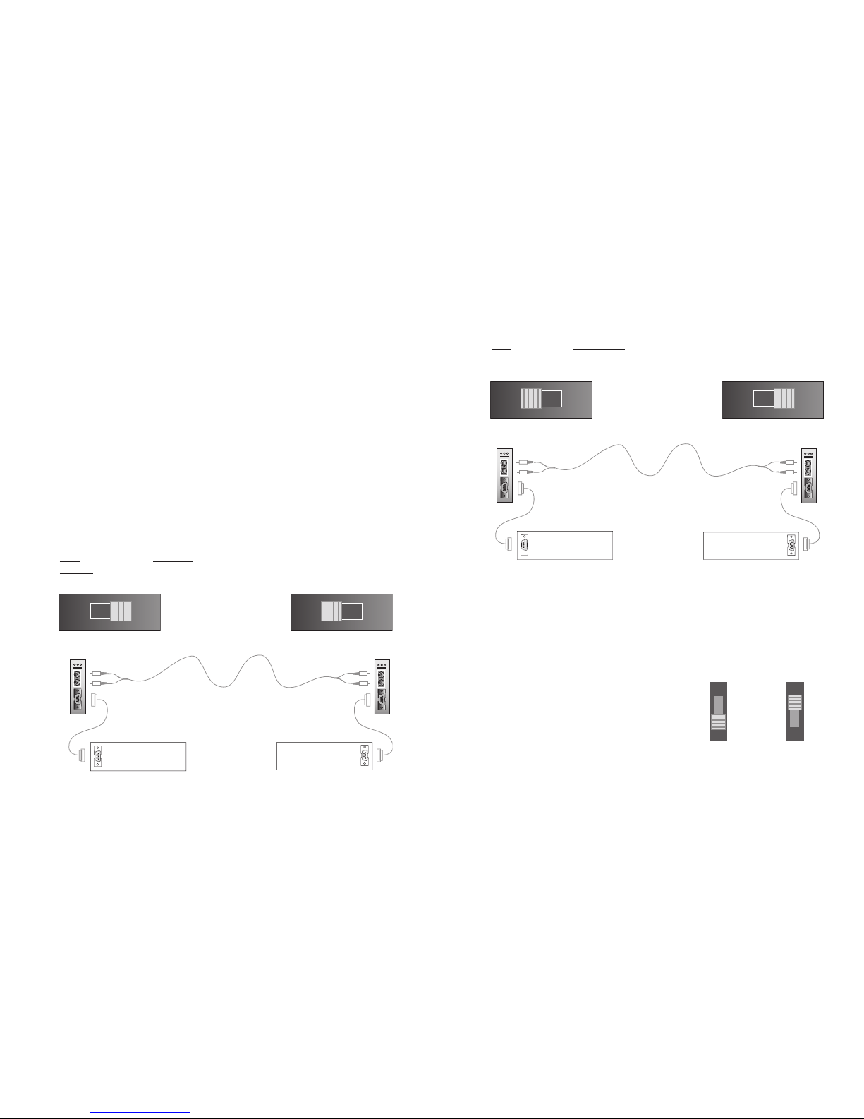
Using Straight-Through RS-232 Cable
DTE Configuration
SRS2F31xx-100
switch set to DTE
SRS2F31xx-100
switch set to DCE
DTE device
DCE device
straight-through
RS-232 cable
straight-through
RS-232 cable
Set the switch to DTE
configuration if the media
converter is connected to a
DCE
device via a straight-
through RS-232 cable.
Set the switch to DCE
configuration if the media
converter is connected to a
DTE
device via a straight-
through RS-232 cable.
DCE Configuration
techsupport@transition.com -- Click the “Transition Now” link for a live Web chat.
3
Set the Loop-Back Switch
The loop-back switch is located on the front panel of the media converter and
is used to debug network faults. (See page 10 in the “Troubleshooting”
section.)
To set the switch, use a small flat-blade
screwdriver or a similar device.
Norm Set the switch to “Norm” for
normal operation.
Loop Set the switch to “Loop” to
enable both fiber and copper
loop-back.
Normal
Operation:
Norm
Loop
Fiber and Coppe
r
Loop-Back:
Norm
Loop
Installation -- Continued
Using Null-Modem RS-232 Cable
DCE Configuration
SRS2F31xx-100
switch set to DCE
SRS2F31xx-100
switch set to DTE
DTE device
DCE device
null-modem
RS-232 cable
null-modem
RS-232 cable
Set the switch to DCE
configuration if the media
converter is connected to a
DCE
device via a null-modem
RS-232 cable.
Set the switch to DTE
configuration if the media
converter is connected to a
DTE
device via a null-modem
RS-232 cable.
DTE Configuration
Page 3
4
24-Hour Technical Support: 1-800-260-1312 -- International: 00-1-952-941-7600
CRS2F31xx-100
Installation -- Continued
CAUTION: Wear a grounding device and observe electrostatic discharge
precautions when setting the hardware/software jumper and installing the media
converter. Failure to observe this caution could result in damage to, and
subsequent failure of, the media converter.
Set the Hardware/Software Jumper
• The jumper is located on the circuit board.
• Use small needle-nose pliers to set the jumper.
Hardware The media converter mode is determined by
the switch settings (see pages 2-3).
Software The media converter mode is determined by
the most-recently saved, on-board
microprocessor settings.
Installing the Slide-in-Module
To install the CRS2F31xx-100 media converter slide-in-module:
1. Locate an empty installation slot on the PointSystem™ chassis.
2. Carefully slide the slide-in-module into the installation slot, aligning the
module with the installation guides.
3. Ensure that the module is firmly seated inside the chassis.
4. Push in and rotate the attached panel fastener screw clockwise to secure
the module to the chassis front.
CFMFF100
CFMFF100
CETCF100
CFETF100
CFETF110
CFMFF100
SPD
PWR
FRX
CRX
FLNK
CLNK
10/100TX
RX
TX
10/100SX
100BASE-TX
RX
TX
100BASE-FX
Link Alert
E
D
0
50½
LA
PWR
RXF
RXC
LNK
COL
LKS
PWR
LKM
10BASE-2
10BASE-FL
LKS
PWR
LKM
LKS
PWR
LKM
Multimode
Singlemode
TX
RX
TX
RX
Multimode
Singlemode
TX
RX
TX
RX
Multimode
Singlemode
TX
RX
TX
RX
I
0
TERM
INIT
RX
TX
LNK
PWR
CPSMM120
SERIAL
10BASE-T
R
E
S
E
T
I
0
Fiber
RS-232
RX
TX
PRX FL
Loop
Norm
CRS2F
Panel Fastener Scre
w
software
mode
hardware
mode
H
S
H
S
J2 J2
Power the Media Converter
The media converter is powered through the PointSystem™ chassis.
techsupport@transition.com -- Click the “Transition Now” link for a live Web chat.
5
Install the Copper Cable
NOTE: Shielded RS-232 cables are required for EMC compliance.
1. Locate or build RS-232 cables with a female connector for the media
converter end and the correct gender connector for the DTE/DCE device
at the other end. And with either straight-through or null-modem cable
configuration.
2. Connect the female RS-232 connector at one end of cable to the male
RS-232 port on the first CRS2F21-100 media converter.
3. Connect the RS-232 connector at the other end of the cable to the RS-232
port on the DTE/DCE device.
9
8
7
6
6
7
8
9
1
5
4
3
2
5
1
2
3
4
Null-modem configuration cable
with handshaking signaling
(Requirements for different equipment may vary.)
Straight-through configuration cable
with handshaking signals
9
8
7
6
9
8
7
6
1
5
4
3
2
1
5
4
3
2
(optional configuration: no connect on pin 9.)
Installation -- Continued
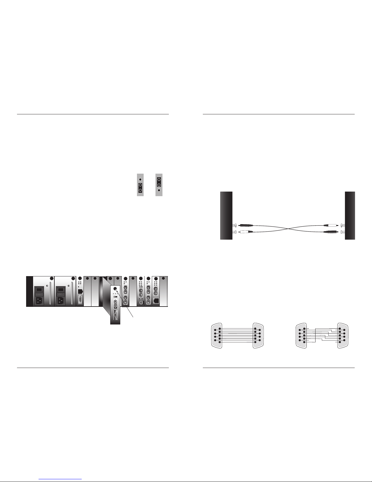
Install the Fiber Cable
1. Locate or build fiber cable with male, two-stranded TX to RX connectors
installed at both ends.
2. Connect the fiber cables to the first CRS2F31xx-100 media converter as
described:
• Connect the male TX cable connector to the female TX port.
• Connect the male RX cable connector to the female RX port.
3. Connect the fiber cables to the other CRS2F31xx-100 media converter as
described:
• Connect the male TX cable connector to the female RX port.
• Connect the male RX cable connector to the female TX port.
Connect the fiber cable
to the first media converter
as shown.
Connect the fiber cable
to the second media
converter, as shown
RX
TX
RX
TX
Page 4

6
24-Hour Technical Support: 1-800-260-1312 -- International: 00-1-952-941-7600
CRS2F31xx-100
Operation
After installation, the media converter should function
without operator intervention. Use the status LEDs to
monitor the media converter operation in the network.
P On The media converter is connected
to external power.
FL On A link has been established with the
fiber connector.
Flashing The media converter is in loop-back
mode.
RX Flashing The RS-232 connector is receiving
data.
Fiber
RS-232
RX
TX
PRX FL
Loop
Norm
CRS2F
SNMP
Use SNMP at an attached terminal or at a remote location to monitor the
media converter by monitoring:
• Local/remote fiber link status
• Local/remote hardware/software mode
• Local/remote loop-back
Also, use SNMP to enter network commands for:
• Local/remote loop-back
See the on-line documentation that comes with Transition Networks
FocalPoint™ software for applicable commands and usage at
www.transition.com.
Remote Management
The CRS2F31xx-100 can remotely manage the SRS2F31xx-100 (the standalone version of the media converter) or another CRS2F31xx-100. For
example, a local CRS2F3111-100 converter (that is installed in a managed
Transition Networks PointSystem™ chassis) is connected, via fiber, to a remote
SRS2F3111-100 converter.
The SNMP section (below) lists the commands that can be used to monitor and
manage both the local and remote media converter.
NOTE: In a managed network, both the local and remote media converters
must be set to “software” mode (see page 4).
techsupport@transition.com -- Click the “Transition Now” link for a live Web chat.
7
Cable Specifications
Fiber Cable
Bit Error Rate: <10-9
Single mode fiber (recommended): 9 µm
Multimode fiber (recommended): 62.5/125 µm
Multimode fiber (optional): 100/140, 85/140, 50/125 µm
CRS2F3111-100 1300 nm multimode
Fiber Optic Transmitter Power: min: -19.0 dBm max: -14.0 dBm
Fiber Optic Receiver Sensitivity: min: -30.0 dBm max: -14.0 dBm
Link Budget: 11.0 dB
CRS2F3113-100 1300 nm multimode
Fiber Optic Transmitter Power: min: -19.0 dBm max: -14.0 dBm
Fiber Optic Receiver Sensitivity: min: -30.0 dBm max: -14.0 dBm
Link Budget: 11.0 dB
CRS2F3114-100 1310 nm single mode
Fiber-optic Transmitter Power: min: -15.0 dBm max: -8.0 dBm
Fiber-optic Receiver Sensitivity: min: -31.0 dBm max: -8.0 dBm
Link Budget: 16.0 dB
CRS2F3115-100 1310 nm single mode
Fiber-optic Transmitter Power: min: -8.0 dBm max: -2.0 dBm
Fiber-optic Receiver Sensitivity: min: -34.0 dBm max: -7.0 dBm
Link Budget: 26.0 dB
The fiber optic transmitters on this device meet Class I Laser safety requirements
per IEC-825/CDRH standards and comply with 21 CFR1040.10 and
21CFR1040.11.
RS-232 Copper Cable
Gauge: 24 to 22 AWG
Maximum Data Rate (asynchronous): 115 kB/s
Maximum Cable Distance: 15 m (50 ft.)
RS-232 Signals:
6
7
8
9
1
2
3
4
5
Data Set Ready
Data Carrier Detect
Request to Send
Clear to Send
Not Used
Receive Data
Transmit Data
Data Terminal Ready
Signal Ground
Protective Ground
Page 5

8
24-Hour Technical Support: 1-800-260-1312 -- International: 00-1-952-941-7600
CRS2F31xx-100
Technical Specifications
For use with Transition Networks Model CRS2F31xx-100 or equivalent
Data Rate 115 kB/s (asynchronous)
Dimensions 3.4" x 5.0" x 0.86" (86 mm x 127 mm x 22 mm)
Weight 3 oz. (91 g) (approximately)
Power Consumption 5 Watts
MTBF 2,613,860 hours (MIL217F2 V5.0) (MIL-HDBD-217F)
6,569,957 hours (Bellcore7 V5.0)
Environment Tmra*: 0 to 50°C (32° to 122° F )
Storage Temp: -15° to 65°C (5° to 149°F)
Humidity: 5 to 95%, non condensing
Altitude: 0 to 10,000 feet
Warranty Lifetime
*Manufacturer’s rated ambient temperature. Tmra range for this slide-in-module
depends on the physical characteristics and the installation configuration of the
Transition Networks PointSystem™ chassis in which this slide-in-module will be
installed.
The information in this user’s guide is subject to change. For the most up-to-date
information on the CRS2F31xx-100 media converter, view the user’s guide online at: www.transition.com
Product is certified by the manufacturer to comply with DHHS Rule 21/CFR,
Subchapter J applicable at the date of manufacture.
CAUTION: Visible and invisible laser radiation when open. Do not stare into
the beam or view directly with optical instruments.
CAUTION: Use of controls, adjustments or the performance of procedures other
than those specified herein may result in hazardous radiation exposure.
techsupport@transition.com -- Click the “Transition Now” link for a live Web chat.
9
Troubleshooting
If the media converter fails, isolate and correct the failure by determining the
answers to the following questions and then taking the indicated action:
1. Is the P (power) LED illuminated?
NO
• Is the media converter inserted properly into the chassis?
• Is the power cord properly installed in the chassis and in the grounded AC
outlet?
• Does the grounded AC outlet provide power?
• Contact Tech Support: 1-800-260-1312, Int’l: 00-1-952-941-7600.
YES
• Proceed to step 2.
2. Is the RX (copper) LED flashing?
NO
• Disconnect and reconnect the RS-232 copper cable to restart the initialization
process.
• Restart the attached device on the other end of the RS-232 cable to restart the
initialization process.
• Contact Tech Support: 1-800-260-1312, Int’l: 00-1-952-941-7600.
YES
• Proceed to step 3.
3. Is the FL (fiber) LED illuminated?
NO
• Check the fiber cables for proper connection.
• Verify that the TX and RX cables on the media converter are connected to the
RX and TX ports, respectively, on the other media converter.
• Contact Tech Support: 1-800-260-1312, Int’l: 00-1-952-941-7600.
YES
• Proceed to step 4.
4. Is the FL (fiber) LED flashing?
YES
• The media converter is in loop-back mode. To disable the loop-back function
in “Hardware” mode, set the loop-back switch to the "Norm" position. In
“Software” mode, at the SNMP interface, select “disable loop-back” option.
• Contact Tech Support: 1-800-260-1312, Int’l: 00-1-952-941-7600.
NO
• Proceed to step 5.
Page 6

10
24-Hour Technical Support: 1-800-260-1312 -- International: 00-1-952-941-7600
CRS2F31xx-100
5. Is Data Transfer Failing?
YES
• Verify the local copper connection by starting a local copper loop-back
(hardware mode: set the loop-back switch on the local media converter to
“loop”, software mode: enter the local copper loop-back command) and then
use a bit error test unit to run a bit error test.
• Verify the local fiber connection by starting a remote fiber loop-back (hardware
mode: set the loop-back switch on the remote media converter to “loop”,
software mode: enter the remote fiber loop-back command) and then use a bit
error test unit to run a bit error test.
• Verify the remote copper connection by starting a remote copper loop-back
(hardware mode: set the loop-back switch on the remote media converter to
“loop”, software mode: enter the remote copper loop-back command) and
then use a bit error test unit on the remote end to run a bit error test.
• Verify remote fiber connection by starting a local copper loop-back (hardware
mode: setting the loop-back switch on the local media converter to “loop”,
software mode: enter the local fiber loop-back command) and then use a bit
error test unit on the remote end to run a bit error test.
NO
• Contact Technical Support: US/Canada: 1-800-260-1312, International: 00-1952-941-7600.
Remote Conver terLocal C onverter
Remote
Device
Bit Er ror Te st
Equipment
w/SN MP Man ageme nt
copper Fiber copper
Remote Conver terLocal C onverter
Remote
Device
Bit Er ror Te st
Equipment
w/SNMP Management
copper Fiber copper
Remote Conver terLocal C onverter
Loca l
Device
Bit Er ror Te st
Equipment
w/SNMP Management
copper Fiber copper
Remote Conver terLocal C onverter
Loca l
Device
w/SNMP Management
copper Fiber copper
Bit Er ror Te st
Equipment
techsupport@transition.com -- Click the “Transition Now” link for a live Web chat.
11
Contact Us
Technical Support
Technical support is available 24 hours a day.
US and Canada: 1-800-260-1312
International: 00-1-952-941-7600
Transition Now
Chat live via the Web with Transition Networks Technical Support.
Log onto www.transition.com and click the Transition Now link.
Web-Based Seminars
Transition Networks provides seminars via live web-based training.
Log onto www.transition.com and click the Learning Center link.
E-Mail
Ask a question anytime by sending an e-mail to our technical support staff.
techsupport@transition.com
Address
Transition Networks
6475 City West Parkway
Minneapolis, MN 55344, U.S.A.
telephone: 952-941-7600
toll free: 800-526-9267
fax: 952-941-2322
Declaration of Conformity
Name of Mfg: Transition Networks
6475 City West Parkway, Minneapolis MN 55344 U.S.A.
Model: CRS2F31xx-100 Series Media Converter
Part Number: CRS2F3111-100, CRS2F3113-100, CRS2F3114-100,
CRS2F3115-100
Regulation: EMC Directive 89/336/EEC
Purpose: To declare that the CRS2F31xx-100 to which this declaration refers is in
conformity with the following standards.
CISPR 22: 1993; EN 55022:1998 Class A; FCC Part 15 Subpart B; EN 55024: 1998;
21 CFR subpart J
I, the undersigned, hereby declare that the equipment specified above conforms to the above
Directive(s) and Standard(s).
September 2007_____
Stephen Anderson, Vice-President of Engineering Date
Page 7

Compliance Information
CISPR22/EN55022 Class A + EN55024
CE Mark
FCC Regulations
This equipment has been tested and found to comply with the limits for a Class A digital
device, pursuant to part 15 of the FCC rules. These limits are designed to provide reasonable
protection against harmful interference when the equipment is operated in a commercial
environment. This equipment generates, uses, and can radiate radio frequency energy and, if
not installed and used in accordance with the instruction manual, may cause harmful
interference to radio communications. Operation of this equipment in a residential area is
likely to cause harmful interference, in which case the user will be required to correct the
interference at the user's own expense.
Canadian Regulations
This digital apparatus does not exceed the Class A limits for radio noise for digital apparatus
set out on the radio interference regulations of the Canadian Department of Communications.
Le présent appareil numérique n'émet pas de bruits radioélectriques dépassant les limites
applicables aux appareils numériques de la Class A prescrites dans le Règlement sur le
brouillage radioélectrique édicté par le ministère des Communications du Canada.
European Regulations
Warning
This is a Class A product. In a domestic environment this product may cause radio
interference in which case the user may be required to take adequate measures.
Achtung !
Dieses ist ein Gerät der Funkstörgrenzwertklasse A. In Wohnbereichen können bei Betrieb
dieses Gerätes Rundfunkstörungen auftreten. In diesem Fäll ist der Benutzer für
Gegenmaßnahmen verantwortlich.
Attention !
Ceci est un produit de Classe A. Dans un environment domestique, ce produit risque de
créer des interférences radioélectriques, il appartiendra alors à l'utilsateur de prende les
measures spécifiques appropriées.
Trademark Notice
All trademarks and registered trademarks are the property of their respective owners.
Copyright Restrictions
© 2003-2005 Transition Networks.
All rights reserved. No part of this work may be reproduced or used in any form or by any
means - graphic, electronic, or mechanical - without written permission from Transition
Networks.
Printed in the U.S.A.
33278.F
 Loading...