

Transition Networks CRMFE1014-200, CRMFE1016-200, CRMFE1018-200, CRMFE1015-200, CRMFE1019-200 User Manual
...Page 1
* Typical maximum cable distance.
Actual distance is dependent upon the
physical characteristics of the network.
Installation . . . . . . . . . . . . . . . . . .3
Operation . . . . . . . . . . . . . . . . . . .7
Cable Specifications . . . . . . . . . .11
Technical Specifications . . . . . . .13
Troubleshooting . . . . . . . . . . . . .14
Compliance Information . . . . . . .16
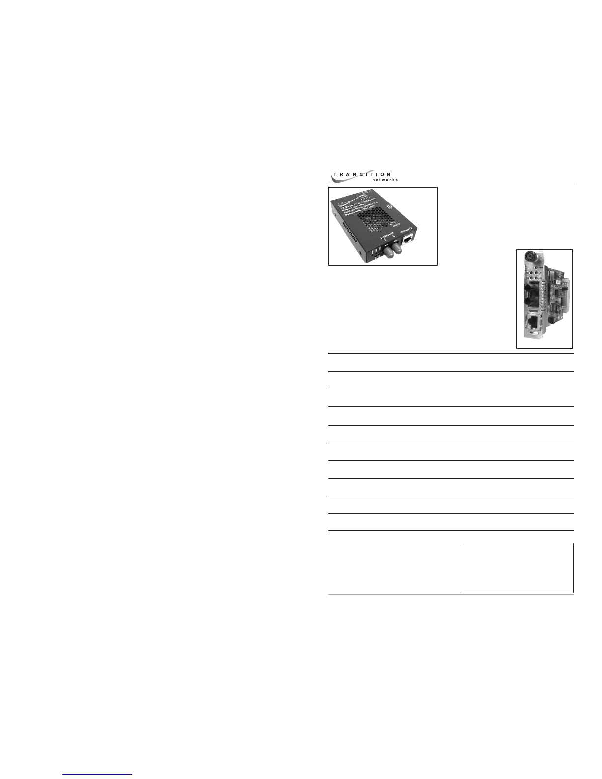
User’s Guide
CRMFE10xx-20x - Chassis
SRMFE10xx-20x - Stand-Alone
• Fast Ethernet
• 100Base-TX to 100Base-FX
• Remote Converter Management
SRMFE10xx-20x
(remote)
Part Number Port One - Copper
100Base-TX
Port Two - Duplex Fiber-Optic
100Base-FX
CRMFE1011-200
SRMFE1011-200
RJ-45
100 m (328 ft)*
ST, 1300 nm multimode
2 km (1.2 miles)*
CRMFE1013-200
SRMFE1013-200
RJ-45
100 m (328 ft)*
SC, 1300 nm multimode
2 km (1.2 miles)*
CRMFE1014-200
SRMFE1014-200
RJ-45
100 m (328 ft)*
SC, 1310 nm single mode
20 km (12.4 miles)*
CRMFE1015-200
SRMFE1015-200
RJ-45
100 m (328 ft)*
SC, 1310 nm single mode
40 km (24.8 miles)*
CRMFE1016-200
SRMFE1016-200
RJ-45
100 m (328 ft)*
SC, 1310 nm single mode
60 km (32.3 miles)*
CRMFE1017-200
SRMFE1017-200
RJ-45
100 m (328 ft)*
SC, 1550 nm single mode
80 km (49.7 miles)*
CRMFE1018-200
SRMFE1018-200
RJ-45
100 m (328 ft)*
MT-RJ, 1300 nm multimode
2 km (1.2 miles)*
CRMFE1019-200
SRMFE1019-200
RJ-45
100 m (328 ft)*
LC, 1310 nm single mode
20 km (12.4 miles)
CRMFE1025-200
SRMFE1025-200
RJ-45
100 m (328 ft)*
MT-RJ, 1310 nm single mode
20 km (12.4 miles)*
(local)
CRMFE10xx-20x
Transition Networks CRMFE10xx-20x and SRMFE10xx-20x
series fast Ethernet media converters connect 100Base-TX
shielded or unshielded twisted-pair copper cable to 100BaseFX fiber-optic cable.
The media converters are designed to be installed in pairs
where the CRMFE10xx-20x is the local media converter and
the SRMFE10xx-20x is the remote media converter.
Page 2
CRMFE10xx-20x / SRMFE10xx-20x
2
24-hour Technical Support: 1-800-260-1312 International: 00-1-952-941-7600
Optional Accessories for the SRMFE10xx-20x (sold separately).
*Typical maximum cable distance. Actual distance is dependent upon the physical
characteristics of the network. (TX = transmit, RX = receive)
Part Number Description
SPS-1872-SA Optional External Power Supply; 18-72VDC Stand-Alone
Output: 12.6VDC, 1.0 A
SPS-1872-PS Optional External Power Supply; 18-72VDC Piggy-back;
Output: 12.6VDC, 1.0 A
E-MCR-04 12-Slot Media Converter Rack (includes universal internal power
supply) 17 x 15 x 5 in. (432 x 381 x 127 mm)
WMBL Optional Wall Mount Brackets; Length: 4.0 in. (102 mm)
WMBV Optional Vertical Mount Bracket; Length: 5.0 in. (127 mm)
WMBD Optional DIN Rail Mount Bracket; Length: 5.0 in. (127 mm)
WMBD-F Optional DIN Rail Mount Bracket (flat); Length: 3.3in. (84 mm)
Part Number Port One - Copper
100Base-TX
Port Two - Fiber-Optic - 100Base-FX
single fiber single mode
CRMFE1029-200
SRMFE1029-200
RJ-45
100 m (328 ft)*
SC, 1310 nm TX / 1550 nm RX
20 km (12.4 miles)*
CRMFE1029-201
SRMFE1029-201
RJ-45
100 m (328 ft)*
SC, 1550 nm TX / 1310 nm RX
20 km (12.4 miles)*
A CRMFE1029-200 or a SRMFE1029-200 is to be installed
with either a CRMFE1029-201 or a SRMFE1029-201;
where one is the local converter and the other is the
remote converter.
CRMFE1029-202
SRMFE1029-202
RJ-45
100 m (328 ft)*
SC, 1310 nm TX / 1550 nm RX
40 km (24.8 miles)*
CRMFE1029-203
SRMFE1029-203
RJ-45
100 m (328 ft)*
SC, 1550 nm TX / 1310 nm RX
40 km (24.8 miles)*
A CRMFE1029-202 or a SRMFE1029-202 is to be installed
with either a CRMFE1029-203 or a SRMFE1029-203;
where one is the local converter and the other is the
remote converter.
CRMFE1039-200
SRMFE1039-200
RJ-45
100 m (328 ft)*
LC,1300 nm multimode,
2 km (1.2miles)*
techsupport@transition.com -- Click the “Transition Now” link for a live Web chat.
3
Installation
CAUTION: Wear a grounding device and observe electrostatic discharge
precautions when setting the 4-position switch and the jumpers and when
installing the CRMFE10xx-20x slide-in-module into the PointSystem™ chassis.
Failure to observe this caution could result in damage to, and subsequent
failure of, the media converter.
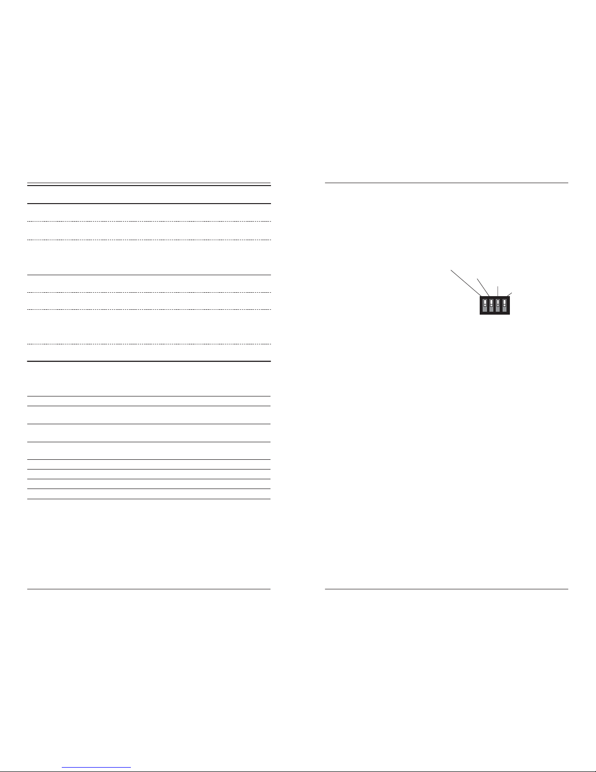
Set the 4-Position Switch
SRMFE10xx-200: The switch is on
the side of the media converter
housing.
CRMFE10xx-20x: The switch is on
the media converter ciruit board.
Use a small flatblade screwdriver or a similar device to set the recessed
switches. Refer to the drawing (above) for the locations of the four individual
switches.
1. Twisted-Pair Auto-Negotiation
up Enable Auto-Negotiation for the copper connection (see page 8).
down Disable Auto-Negotiation for the copper connection.
2. Twisted-Pair Pause Feature
up Enable Pause feature for the copper connection (see page 9).
down Disable Pause feature for the copper connection
3. Link Pass-Through
up Enable Link Pass-Through (see page 8).
down Disable Link Pass-Through.
4. Far-End Fault
up Enable Far-End Fault (see page 9).
down Disable Far-End Fault.
Link Pass-Through (up = enable)
Pause (up = enable)
A
uto-Negotiation (up = enable)
Far End Fault
(up = enable)
1234
Page 3
CRMFE10xx-20x / SRMFE10xx-20x
4
24-hour Technical Support: 1-800-260-1312 International: 00-1-952-941-7600
Installation -- Continued
Set the Jumpers
Both jumpers are located on the media converter circuit board.
Enable/Disable AutoCross™
The AutoCross jumper is labeled “J2”. The drawing illustrates the two
settings:
Disable Either straight-through or crossover twisted-
pair copper cable must be installed,
according to the site requirements
Enable The media converter connects automatically
to either straight-through or crossover
twisted-pair copper cable (see page 9).
NOTE: Factory default is “enable AutoCross.” Transition networks
recommends leaving the deivce in the “enable” mode.
Hardware/Software Mode
The Hardware/Software mode jumper is labeled “J6”. The drawing illustrates
the two settings:
Hardware The media converter mode is determined by
the 4-position switch settings (see the “4Position switch” section on page 3).
Software The media converter mode is determined by
the most-recently saved, on-board
microprocessor settings.
Setting the Jumpers
To set the jumpers on the CRMFE10xx-20x, use small needle-nosed pliers or
similar device to move the jumper to the desired position.
To set the jumpers on the SRMFE10xx-20x:
1. Using a small screwdriver, remove the four (4) screws that secure the
cover to the media converter.
2. Carefully remove the cover from the media converter and locate the
jumper on the circuit board.
3. Using small needle-nosed pliers or similar device, move the jumper to
the desired position.
4. Carefully replace the cover on the media converter and replace the four
(4) screws that secure the cover to the media converter.
Software Mode
Hardware Mode
H
S
H
S
Disable Autocross
Enable Autocross
DE
DE
techsupport@transition.com -- Click the “Transition Now” link for a live Web chat.
5
Installation -- Continued
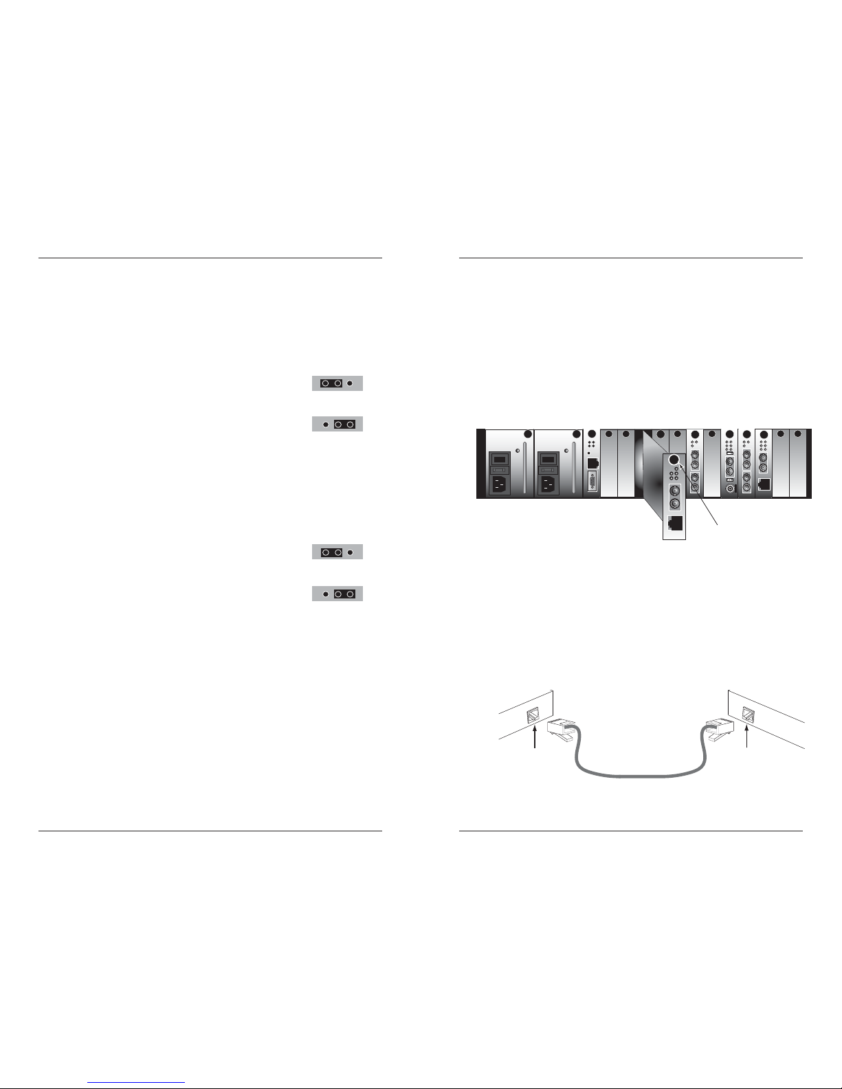
Install the CRMFE10xx-20x Slide-In-Module
CAUTION: Slots in the PointSystem™ chassis without a slide-in-module
installed MUST have a protective plate covering the empty slot for Class A
and/or Class B compliance.
To install the CRMFE10xx-20x media converter slide-in-module:
1. Locate an empty installation slot on the PointSystem™ chassis.
2. Carefully slide the slide-in-module into the installation slot, aligning the
module with the installation guides.
3. Ensure that the module is firmly seated inside the chassis.
4. Push in and rotate the attached panel fastener screw clockwise to secure
the module to the chassis front.
CFMFF100
CFMFF100
CETCF100
CFETF100
CFMFF100
SPD
PWR
FRX
CRX
FLNK
CLNK
10/100TX
RX
TX
10/100SX
100BASE-TX
RX
TX
100BASE-FX
Link Alert
E
D
0
50½
LA
PWR
RXF
RXC
LNK
COL
LKS
PWR
LKM
10BASE-2
10BASE-FL
LKS
PWR
LKM
LKS
PWR
LKM
Multimode
Singlemode
TX
RX
TX
RX
Multimode
Singlemode
TX
RX
TX
RX
Multimode
Singlemode
TX
RX
TX
RX
I
0
TERM
INIT
RX
TX
LNK
PWR
CPSMM120
SERIAL
10BASE-T
R
E
S
E
T
I
0
panel fastener screw
PWR
Install the Copper Cable
1. Locate or build 100Base-TX compliant copper cables with male, RJ-45
connectors installed at both ends.
2. Connect the RJ-45 connector at one end of the cable to the RJ-45 port on
the CRMFE10xx-20x (local) media converter.
3. Connect the RJ-45 connector at the other end of the cable to the RJ-45
port on the other (local) device (switch, workstation, etc.).
4. Repeat steps 2 and 3 for the SRMFE10xx-20x (remote) media converter.
5. Connect the RJ-45 connector at the other end of the cable to the RJ-45
port on the other (remote) device (switch, workstation, etc.).
RJ-45 port
on the other device
(switch, work station, etc.)
RJ-45 port
on the media
converter
Page 4

CRMFE10xx-20x / SRMFE10xx-20x
6
24-hour Technical Support: 1-800-260-1312 International: 00-1-952-941-7600
Installation -- Continued
Install the Fiber Cable
1. Locate or build 100Base-FX compliant fiber cable with male, twostranded TX to RX connectors installed at both ends.
2. Connect the fiber cables to the CRMFE10xx-20x (local) media converter
as described:
• Connect the male TX cable connector to the female TX port.
• Connect the male RX cable connector to the female RX port.
3. Connect the fiber cables to the SRMFE10xx-20x (remote) media
converter as described:
• Connect the male TX cable connector to the female RX port.
• Connect the male RX cable connector to the female TX port.
Connect the fiber cable
to the CRMFE10xx-200
media converter as shown.
Connect the fiber cable
to the SRMFE10xx-200
media converter as shown
RX
TX
RX
TX
Power the Media Converter
The CRMFE10xx-20x slide-in-module media converter is powered through the
Transition Networks PointSystem™ chassis.
To power the SRMFE10xx-20x media converter:
AC
The external power supply provided with this device is UL listed by the
manufacturer of the power supply.
1. Connect the barrel connector on the power adapter to the media
converter’s power port (located on the back of the media converter).
2. Connect the power adapter plug to AC power.
3. Verify that the media converter is powered by observing the illuminated
LED power indicator light.
DC
Consult the user’s guide for the Transition Networks SPS1872-xx DC external
power supply for powering the media converter.
techsupport@transition.com -- Click the “Transition Now” link for a live Web chat.
7
Operation
Status LEDs
Use the status LEDs to monitor the CGRFE10xx-20x and the SGRFE10xx-20x
in the network.
PWR Power On = Connection to the external power.
RXF Fiber Receive Flashing = Reception of the data on the fiber link.
LKF Fiber Link On = Fiber link connection.
RXC Copper Receive Flashing = Data reception on the copper link.
LKC Copper Link On = Copper link connection.
PWR
RXF
LKF
100Base-TX
RXTX
100Base-FX
RXC
LKC
CRMFE10xx-200 SRMFE10xx-200
PWR
RXF
LKF
TX
RXC
LKC
CRMFE200
Page 5

CRMFE10xx-20x / SRMFE10xx-20x
8
24-hour Technical Support: 1-800-260-1312 International: 00-1-952-941-7600
Operation -- Continued
Product Features
Secure and Transparent Data
The data is both secure and transparent because it uses none of the Ethernet
bandwidth. In addition, the data exists outside the normal Ethernet framing
format.
Auto-Negotiation
The Auto-Negotiation feature allows the media converter automatically
configures itself to achieve the best possible mode of operation over a link.
The media converter broadcasts its speed (10Mb/s, 100Mb/s, or 1000Mb/s)
and duplex capabilities (full or half) to the other device and negotiates the best
mode of operation. Auto-Negotiation allows quick and easy installation
because the optimal link is established automatically. No user intervention is
required to determine the best mode of operation.
A scenario where the media converter is linked to a non-negotiating device is
a case where the user may want to disable Auto-Negotiation. In this instance,
the mode of operation will drop to the least common denominator between
the two devices (e.g. 10 Mb/s, half-duplex). Disabling this feature gives the
user the ability to force the connection to the best mode of operation.
NOTE: The media converter does NOT support rate conversion between
10Mb/s, 100Mb/s, and 1000Mb/s network devices.
Link Pass-Through
The Link Pass-Through feature allows the media converter to monitor both the
fiber and copper RX (receive) ports for loss of signal. In the event of a loss of
an RX signal on one media port, the media converter will automatically
disable the TX (transmit) signal of the other media port, thus, “passing
through” the link loss.
Remote Management Function
The SRMFE10xx-20x stand-alone media converter can be remotely managed
when connected via fiber cable to a local CRMFE10xx-20x slide-in-module
media converter that is installed in a managed Transition Networks
PointSystem™ chassis.
See page 10 for the available SNMP commands that enable the user to both
monitor and manage both the local and remote media converters.
4
1
Media
Converter A
Media
Converter B
Near-End
Device
Far-End
Device
original fault
on the copper link
media converter B
disables the copper lin
k
media converter A
disables the fiber TX link
3
2
media converter B
loses the fiber RX link
techsupport@transition.com -- Click the “Transition Now” link for a live Web chat.
9
Operation -- Continued
Product Features -- Continued
Far-End Fault
When a fault occurs on an incoming fiber link (1), the media converter
transmits a Far-End Fault signal on the outgoing fiber link (2). In addition the
Far-End Fault signal also activates the Link Pass-Through, which, in turn,
disables the link on the copper portion of the network (3) and (4).
Pause
The pause feature is used to temporarily suspend data transmission in order to
relieve buffer congestion. If a media converter needs some time to clear
network congestion, it will send a pause signal to the media converter at the
other end, which will wait a predetermined amount of time before retransmitting the data. This feature reduces data bottlenecks, allows for a more
efficient use of the network devices, and prevents the loss of valuable data.
In Hardware mode, the pause feature can be set to
• Disable (i.e., no pause)
• Enable (i.e., symmetrical pause)
In Software mode, the pause feature can be set to one of four settings:
• Disable (i.e., no pause)
• Symmetrical pause
• Asymmetric TX (transmit) pause
• Asymmetric RX (receive) pause
Enable the pause feature if it is present on ALL network devices attached to
the media converter(s). Otherwise, disable the pause feature.
AutoCross™
The AutoCross feature allows either straight-through (MDI) or crossover (MDIX) cables to be used when connecting to 100Base-TX devices, such as hubs,
transceivers, or network interface cards (NICs). AutoCross determines the
characteristics of the cable connection and automatically configures the unit
to link up, regardless of the cable configuration.
NOTE: Factory default is “enable AutoCross.” Transition networks
recommends leaving the deivce in the “enable” mode.
Far-End Fault
si
g
nal is sent
Media
Converter A
Media
Converter B
Near-End
Device
Far-End
Device
original fault
on the fiber link
media converter B
disables the co
pp
er lin
k
media converter A
disables the co
pp
er link
3
4
2
1
Page 6

CRMFE10xx-20x / SRMFE10xx-20x
10
24-hour Technical Support: 1-800-260-1312 International: 00-1-952-941-7600
Operation -- Continued
Product Features -- Continued
SNMP
See the on-line documentation that comes with Transition Networks
FocalPoint™ software for applicable commands and usage.
Use SNMP at an attached terminal or at a remote location to monitor the local
CRMFE10xx-20x media converter by monitoring:
• Copper and fiber link status.
• Enable/disable Auto-Negotiation.
• Enable/disable pause feature.
• Enable/disable Link Pass-Through.
• Enable/disable Far-End Fault.
• Enable/disable AutoCross.
• Enable/disable the CRMFE10xx-20x media converter.
• Uptime (d:h:m:s) counter with reset.
• TX (copper) receive bytes and FX (fiber) receive bytes counters (a
single reset command resets both functions).
• MSC TX (transmit) bytes and MSC RX (receive) bytes counters (a
single reset command resets both functions).
• Bandwidth allocation in 64Kbytes/s units. (Two fields, one for TX
(copper) to FX (fiber) and one for FX (fiber) to TX (copper), are
available.)
Also, use SNMP to monitor the remote SRMFE10xx-20x media converter with
the following network commands:
• Copper and fiber link status.
• Enable/disable Auto-Negotiation.
• Enable/disable pause feature.
• Enable/disable Link Pass-Through.
• Enable/disable Far-End Fault.
• Enable/disable AutoCross.
• Uptime (d:h:m:s) counter with reset command.
• Loopback: Data sent fom the TX interface is intercepted and looped
back the RX interface. The data is not sent out and data coming into
the receiver from the copper cable is ignored.
techsupport@transition.com -- Click the “Transition Now” link for a live Web chat.
11
Cable Specifications
The physical characteristics must meet or exceed IEEE 802.3™ specifications.
Fiber Cable
Bit Error Rate: <10-9
Single mode fiber (recommended): 9 µm
Multimode fiber (recommended): 62.5/125 µm
Multimode fiber (optional): 100/140, 85/140, 50/125 µm
CRMFE1011-200, SRMFE1011-200 1300 nm multimode
Fiber Optic Transmitter Power: min: -19.0 dBm max: -14.0 dBm
Fiber Optic Receiver Sensitivity: min: -30.0 dBm max: -14.0 dBm
Link Budget: 11.0 dB
CRMFE1013-200, SRMFE1013-200 1300 nm multimode
Fiber Optic Transmitter Power: min: -19.0 dBm max: -14.0 dBm
Fiber Optic Receiver Sensitivity: min: -30.0 dBm max: -14.0 dBm
Link Budget: 11.0 dB
CRMFE1014-200, SRMFE1014-200 1310 nm single mode
Fiber-optic Transmitter Power: min: -15.0 dBm max: -8.0 dBm
Fiber-optic Receiver Sensitivity: min: -31.0 dBm max: -8.0 dBm
Link Budget: 16.0 dB
CRMFE1015-200, SRMFE1015-200 1310 nm single mode
Fiber-optic Transmitter Power: min: -8.0 dBm max: -2.0 dBm
Fiber-optic Receiver Sensitivity: min: -34.0 dBm max: -7.0 dBm
Link Budget: 26.0 dB
CRMFE1016-200, SRMFE1016-200 1310 nm single mode
Fiber-optic Transmitter Power: min: -5.0 dBm max: 0.0 dBm
Fiber-optic Receiver Sensitivity: min: -34.0 dBm max: -7.0 dBm
Link Budget: 29.0 dB
CRMFE1017-200, SRMFE1017-200 1550 nm single mode
Fiber-optic Transmitter Power: min: -5.0 dBm max: 0.0 dBm
Fiber-optic Receiver Sensitivity: min: -34.0 dBm max: -7.0 dBm
Link Budget: 29.0 dB
CRMFE1018-200, SRMFE1018-200 1300 nm multimode
Fiber-optic Transmitter Power: min: -19.0 dBm max: -14.0 dBm
Fiber-optic Receiver Sensitivity: min: -33.5 dBm max: -14.0 dBm
Link Budget: 14.5 dB
CRMFE1019-200, SRMFE1019-200 1310 nm single mode
Fiber-optic Transmitter Power: min: -15.2 dBm max: -8.0 dBm
Fiber-optic Receiver Sensitivity: min: -32.5 dBm max: -3.0 dBm
Link Budget: 17.3 dB
CRMFE1025-200, SRMFE1025-200 1310 nm single mode
Fiber-optic Transmitter Power: min: -11.0 dBm max: -3.0 dBm
Fiber-optic Receiver Sensitivity: min: -20.0 dBm max: -3.0 dBm
Link Budget: 9.0 dB
Page 7

CRMFE10xx-20x / SRMFE10xx-20x
12
24-hour Technical Support: 1-800-260-1312 International: 00-1-952-941-7600
Cable Specifications -- Continued
The physical characteristics must meet or exceed IEEE 802.3™ specifications.
Fiber Cable -- Continued
CRMFE1029-200, SRMFE1029-200 1310nm TX/1550nm RX single mode
Fiber-optic Transmitter Power: min: -13.0 dBm max: -6.0 dBm
Fiber-optic Receiver Sensitivity: min: -32.0 dBm max: -3.0 dBm
Link Budget: 19.0 dB
CRMFE1029-201, SRMFE1029-201 1550nm TX/1310nm RX single mode
Fiber-optic Transmitter Power: min: -13.0 dBm max: -6.0 dBm
Fiber-optic Receiver Sensitivity: min: -32.0 dBm max: -3.0 dBm
Link Budget: 19.0 dB
CRMFE1029-202, SRMFE1029-202 1310nm TX/1550nm RX single mode
Fiber-optic Transmitter Power: min: -8.0 dBm max: -3.0 dBm
Fiber-optic Receiver Sensitivity: min: -33.0 dBm max: -3.0 dBm
Link Budget: 25.0 dB
CRMFE1029-203, SRMFE1029-203 1550nm TX/1310nm RX single mode
Fiber-optic Transmitter Power: min: -8.0 dBm max: -3.0 dBm
Fiber-optic Receiver Sensitivity: min: -33.0 dBm max: -3.0 dBm
Link Budget: 25.0 dB
CRMFE1039-200, SRMFE1039-200 1550nm TX/1310nm RX multimode
Fiber-optic Transmitter Power: min: -19.0 dBm max: -14.0 dBm
Fiber-optic Receiver Sensitivity: min: -30.0 dBm max: -14.0 dBm
Link Budget: 11.0 dB
The fiber optic transmitters on this device meet Class I Laser safety
requirements per IEC-825/CDRH standards and comply with 21 CFR1040.10
and 21CFR1040.11.
Copper Cable
Category 5:
Gauge: 24 to 22 AWG
Attenuation: 22.0 dB /100m @ 100 MHz
Maximum Cable Distance: 100 meters
• Straight-through OR crossover cable may be used.
• Shielded (STP) OR unshielded (UTP) twisted-pair may be used.
• Pins 1&2 and 3&6 are the two active pairs in an Ethernet network .
• RJ-45 Pin-out: Pin 1 = TD+, Pin 2 = TD-, Pin 3 = RD+, Pin 6 = RD-
• Use only dedicated wire pairs for the active pins:
(e.g., blue/white & white/blue, orange/white & white/orange, etc.)
• Do not use flat or silver satin wire.
Crossover Cable
1
2
3
6
Straight-Through Cable
Twisted Pair #1
Twisted Pair #1
Twisted Pair #2
Twisted Pair #2
1
2
3
6
1
2
3
6
1
2
3
6
techsupport@transition.com -- Click the “Transition Now” link for a live Web chat.
13
Technical Specifications
For use with Transition Networks Model CRMFE10xx-20x and SRMFE10xx-20x.
Standards: IEEE 802.3™, 2000
Data Rate: 100 Mb/s
Power Consumption: 3.8 W, 320 mA @ 11.88VDC
CRMFE10xx-20x:
Case Dimensions: 3.4" x 0.87" x 5.0" (86 mm x 22 mm x 127 mm)
Weight: 4 oz (113 g) (approximate)
MTBF 483,000 hours
(MIL217F2 V5.0) (MIL-HDBK-217F)
1,344,000 hours (Bellcore7 V5.0)
SRMFE10xx-20x:
Case Dimensions: 3.25" x 1" x 4.7" (83 mm x 25 mm x 119 mm)
Weight: 9.6 oz (278 g) (approximate)
MTBF 49,000 hours
(MIL217F2 V5.0) (MIL-HDBK-217F)
123,000 hours (Bellcore7 V5.0)
Power Supply: 12VDC, 0.5 A (North America)
12VDC, 0.41A (Europe, Japan, Latin America)
12VDC, 1.25A (Australia, N.Z., S. Africa, UK)
Environment: Tmra*: 0° to 50°C (32° to 122°F)
Storage Temperature: -15° to 65°C (5° to 145°F)
Humidity: 5 to 95%, non condensing
Altitude: 0 to 10,000 feet
Warranty: Lifetime
*Manufacturer’s rated ambient temperature: Tmra range for the CRMFE10xx-20x
depends on the Transition Networks PointSystem™ chassis in which this SlideIn-Module will be installed.
The information in this user’s guide is subject to change. For the most up-to-date
information on the CRMFE10xx-20x / SRMFE10xx-20x media converter, view the
user’s guide on-line at: www.transition.com.
Product is certified by the manufacturer to comply with DHHS Rule 21/CFR,
Subchapter J applicable at the date of manufacture.
CAUTION: Visible and invisible laser radiation when open. Do not stare into
beam or view directly with optical instruments.
CAUTION: Use of controls, adjustments or the performance of procedures other
than those specified herein may result in hazardous radiation exposure.
Page 8

CRMFE10xx-20x / SRMFE10xx-20x
14
24-hour Technical Support: 1-800-260-1312 International: 00-1-952-941-7600
Troubleshooting
1. Is the PWR LED on either media converter illuminated?
NO
• Is the power adapter on the SRMFE10xx-20x the proper type of
voltage and cycle frequency for an AC outlet?
• Is the power adapter properly installed in the SRMFE10xx-20x media
converter and in the outlet?
• Is the CRMFE10xx-20x media converter inserted properly into the
chassis?
• Is the power cord properly installed in the PointSystem™ chassis and
in the grounded AC outlet?
• Does the grounded AC outlet provide power?
• Contact Technical Support: US/Canada: 1-800-260-1312,
International: 00-1-952-941-7600.
YES
• Proceed to step 2.
2. Is the LKC LED illuminated?
NO
• Check the twisted pair cables for proper connection.
• Contact Technical Support: US/Canada: 1-800-260-1312,
International: 00-1-952-941-7600.
YES
• Proceed to step 3.
3. Is the LKF LED illuminated?
NO
• Check the fiber cables for proper connection.
• Verify that the TX and RX cables on one media converter are
connected to the RX and TX ports, respectively, on the other media
converter.
• Contact Technical Support: US/Canada: 1-800-260-1312,
International: 00-1-952-941-7600.
YES
• Proceed to step 4.
4. Is the RXC LED flashing?
NO
• If there is no activity on the 100Base-TX port, proceed to step 5.
• If there is activity on the 100Base-TX port, disconnect and reconnect
the 100Base-TX cable to restart the initialization process.
• Restart the workstation to restart the initialization process.
• Contact Technical Support: US/Canada: 1-800-260-1312,
International: 00-1-952-941-7600.
YES
• Proceed to step 5.
techsupport@transition.com -- Click the “Transition Now” link for a live Web chat.
15
Contact Us
Technical Support
Technical support is available 24 hours a day.
US and Canada: 1-800-260-1312
International: 00-1-952-941-7600
Transition Now
Chat live via the Web with Transition Networks Technical Support.
Log onto www.transition.com and click the Transition Now link.
Web-Based Seminars
Transition Networks provides seminars via live web-based training.
Log onto www.transition.com and click the Learning Center link.
E-Mail
Ask a question anytime by sending an e-mail to our technical support staff.
techsupport@transition.com
Address
Transition Networks
6475 City West Parkway
Minneapolis, MN 55344, USA
telephone: 952-941-7600
toll free: 800-526-9267
fax: 952-941-2322
Troubleshooting -- Continued
5. Is the RXF LED flashing?
NO
• If there is no activity on the 100Base-FX port, continue below
• If there is activity on the 100Base-FX port, disconnect and reconnect
the 100Base-FX cable to restart the initialization process.
• Verify that TX and RX cables on one media converter are connected
to RX and TX ports, respectively, on the other media converter.
• Restart the workstation to restart the initialization process.
• Contact Technical Support: US/Canada: 1-800-260-1312,
International: 00-1-952-941-7600.
YES
• Contact Technical Support: US/Canada: 1-800-260-1312,
International: 00-1-952-941-7600.
Page 9

Compliance Information
EN55022 Class A & B + EN55024; CE Mark
FCC Regulations:
This equipment has been tested and found to comply with the limits for a
Class A & B digital device, pursuant to part 15 of the FCC rules. These limits are designed to
provide reasonable protection against harmful interference when the equipment is operated
in a commercial environment. This equipment generates, uses, and can radiate radio
frequency energy and, if not installed and used in accordance with the instruction manual,
may cause harmful interference to radio communications. Operation of this equipment in a
residential area is likely to cause harmful interference, in which case the user will be required
to correct the interference at the user's own expense.
Canadian Regulations: This digital apparatus does not exceed the Class A & B limits for
radio noise for digital apparatus set out on the radio interference regulations of the Canadian
Department of Communications.
Le présent appareil numérique n'émet pas de bruits radioélectriques dépassant les limites
applicables aux appareils numériques de la Class A & B prescrites dans le Règlement sur le
brouillage radioélectrique édicté par le ministère des Communications du Canada.
CAUTION: RJ connectors are NOT INTENDED FOR CONNECTION TO THE
PUBLIC TELEPHONE NETWORK. Failure to observe this caution could result in
damage to the public telephone network.
Der Anschluss dieses Gerätes an ein öffentlickes Telekommunikationsnetz in den EGMitgliedstaaten verstösst gegen die jeweligen einzelstaatlichen Gesetze zur Anwendung der
Richtlinie 91/263/EWG zur Angleichung der Rechtsvorschriften der Mitgliedstaaten über
Telekommunikationsendeinrichtungen einschliesslich der gegenseitigen Anerkennung ihrer
Konformität.
Declaration of Conformity
Name of Mfg: Transition Networks
6475 City West Parkway, Minneapolis MN 55344 U.S.A.
Model: xRMFE10xx-20x Series Media Converters
Part Number(s): CRMFE1011-200, CRMFE1013-200, CRMFE1014-200, CRMFE1015-200,
CRMFE1016-200, CRMFE1017-200, CRMFE1018-200, CRMFE1019-200 CRMFE1025-200,
CRMFE1029-200, CRMFE1029-201, CRMFE1029-202, CRMFE1029-203, CMFE1039-200
SRMFE1011-200, SRMFE1013-200, SRMFE1014-200, SRMFE1015-200, SRMFE1016-200,
SRMFE1017-200, SRMFE1018-200, SRMFE1019-200, SRMFE1025-200, SRMFE1029-200,
SRMFE1029-201, SRMFE1029-202, SRMFE1029-203, SMFE1039-200
Regulation: EMC Directive 89/336/EEC
Purpose: To declare that the
xRMFE10xx-20x
to which this declaration refers is in conformity
with the following standards.
CISPR 22: 1993; EN 55022:1998 A1:2000 Class A & B; EN 55024: 1998; FCC Part 15 Subpart
B; EN 61000-3-2:2000; EN 61000-3-3: 1995 A1:2001; 21CFR subpart J
I, the undersigned, hereby declare that the equipment specified above conforms to the above
Directive(s) and Standard(s).
Setptember 16, 2005
Stephen Anderson, Vice-President of Engineering Date
Trademark Notice
All trademarks and registered trademarks are the property of their respective owners.
Copyright Restrictions: © 2003-2005 Transition Networks. All rights reserved. No part of
this work may be reproduced or used in any form or by any means - graphic, electronic, or
mechanical - without written permission from Transition Networks.
Printed in the U.S.A.
33268.E
 Loading...