

Page 1
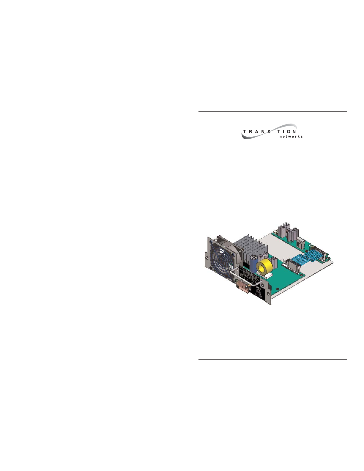
CPSMP-210
48VDC Power Supply
&
CPSMP-220
24VDC Power Supply
PointSystem™ Chassis:
CPSMC18xx-xxx accessory
CPSMC19xx-100 accessory
User’s Manual
33187.C
Page 2

CPSMP-210 48VDC and CPSMP-220 24VDC Power Supplies
2
24-Hour Technical Support: 1-800-260-1312 -- International: 00-1-952-941-7600
Table of Contents
Cautions and Warnings 3
Definitions . . . . . . . . . . . . . . . . . . . . . . . . . . . . . . . . . . . . . . . . . . . . . .3
Cautions and warnings in this manual . . . . . . . . . . . . . . . . . . . . . . . . .3
Description 4
Power supply component identification . . . . . . . . . . . . . . . . . . . . . . .4
Notices . . . . . . . . . . . . . . . . . . . . . . . . . . . . . . . . . . . . . . . . . . . . . . . . .4
Installation 5
Configuration switch . . . . . . . . . . . . . . . . . . . . . . . . . . . . . . . . . . . . .5
Configuration switch-postion explanations . . . . . . . . . . . . . . . . . . . . .5
Configuring two power supplies in one chassis . . . . . . . . . . . . . . . . .6
Installing the power supply into a PointSystem chassis . . . . . . . . . . .6
Power source circuit requirements . . . . . . . . . . . . . . . . . . . . . . . . . . . .8
Equipment ground . . . . . . . . . . . . . . . . . . . . . . . . . . . . . . . . . . . . . . . .8
Disconnect requirements . . . . . . . . . . . . . . . . . . . . . . . . . . . . . . . . . . .8
Connecting external power . . . . . . . . . . . . . . . . . . . . . . . . . . . . . . . . .8
Redundant (failover) chassis power supply . . . . . . . . . . . . . . . . . . . . .9
Maintenance 10
Replacing the power supply . . . . . . . . . . . . . . . . . . . . . . . . . . . . . . . . .10
Configuring the power supply . . . . . . . . . . . . . . . . . . . . . . . . . . . . . . .10
Replacing the fuse . . . . . . . . . . . . . . . . . . . . . . . . . . . . . . . . . . . . . . . .11
Technical Specification 12
Troubleshooting 13
Contact Us 14
Compliance Information 15
techsupport@transition.com -- Click the “Transition Now” link for live Web chat.
3
!
!
!
!
!
!
!
Cautions and Warnings
Definitions
Cautions indicate potential damage to equipment.
Warnings indicate potential hazard or injury to people.
Cautions and warnings in this manual
Cautions and Warnings are explained here and placed throughout this manual where
appropriate.
CAUTION
: While installing or servicing the power supply, wear a grounding
device and observe all electrostatic discharge precautions. Failure to observe this
caution could result in damage to, or failure of the power supply.
WARNING:
Do not connect the power supply to an external power source before
installing it into the chassis. Failure to observe this warning could result in an
electrical shock, even death.
WARNING:
The power supply has a provision for grounding. Equipment
grounding is vital to ensure safe operation. The installer must ensure that the power
supply is properly grounded during and after installation. Failure to observe this
warning could result in an electric shock, even death.
WARNING:
A readily accessible, suitable National Electrical Code (NEC) or
local electrical code approved disconnect device and branch-circuit protector must
be part of the building's installed wiring to accommodate permanently connected
equipment. Failure to observe this warning could result in an electric shock, even
death.
WARNING:
Turn the power supply and external power source OFF and ensure
that the power supply is disconnected from the external power source before
performing any maintenance. Failure to observe this warning could result in an
electrical shock, even death.
WARNING:
Ensure that the disconnect device for the external power source is
OPEN (turned OFF) before disconnecting or connecting the power leads to the
power supply. Failure to observe this warning could result in an electric shock,
even death.
!
!
!
!
!
!
CPSMP-210 48VDC and CPSMP-220 24VDC Power Supplies
Page 3
CPSMP-210 48VDC and CPSMP-220 24VDC Power Supplies
4
24-Hour Technical Support: 1-800-260-1312 -- International: 00-1-952-941-7600
Notices
• The CPSMP-210 48VDC and CPSMP-220 24VDC power supplies must be
installed by qualified technical personnel only. Transition networks assumes no
responsibility for the improper installation, set up or use of these power supplies.
• The information in this user’s guide is subject to change. For the most up-to-date
information, see the user’s guide on-line at www.transition.com.
Figure 1: Power Supply Components
Description
Transition Networks’ CPSMP-210 48VDC and CPSMP-220 24VDC power supplies
can deliver power or provide optional, redundant DC power to the CPSMC18xx-xxx
and the CPSMC19xx-100 PointSystem chassis.
Power supply component identification
See Figure 1:
• Power ON LED (green)
• External power connector (terminal block) for connecting an external power
source to the power supply
• Fuse (on the power supply board)
• ON/OFF switch, when in the ON position power is supplied to the PointSystem
chassis
• Four-position configuration switch (located on IFO board) sets power-supply
functionality
• Chassis ground screw
• Fan
• Handle for installing and removing the power supply
Power ON LED (green)
(holder not shown) Fuse
Four-Position
Configuration Switch
ON/OFF Switch
± Power-Lead Terminal
Block Connectors
Grounding Screw
Fan
Instant Failove r (IFO
)
Board
Power Supply Board
Handle
techsupport@transition.com -- Click the “Transition Now” link for a live Web chat.
5
Installation
IMPORTANT
• All installation and service must be performed by qualified personnel only.
• Read and follow all CAUTION and WARNING notices, instructions marked on
the product, including this manual.
The CPSMP-210 and CPSMP-220 power supply can replace an existing DC power
supply. Either can be installed as the redundant power supply in an AC- or DCpowered PointSystem chassis.
CAUTION:
While installing or servicing the power supply, wear a grounding
device and observe all electrostatic discharge precautions. Failure to observe this
caution could result in damage to, or failure of the power supply.
Configuration switch
Located on the IFO board, the power supply has a four-position configuration switch,
shown in Figure 2.
Configuration switch-position explanations
The management/manual switch establishes PointSystem software or manual control
of master/slave switch settings for the power supply.
• When the management/manual switch is in the management position, powersupply configuration can be set to master or slave via software.
• When the management/manual switch is in the manual position, power-supply
configuration is set manually to master or slave and cannot be changed via
software.
• When the master/slave switch is in the master position, the power supply is the
primary power source for the chassis.
• When the master/slave switch is in the slave position (additional power supply),
the power supply is used for redundancy (failover) purposes, in the event of a
master power-supply failure.
Four-Position Configurat ion Switch
Instant Failover (IF O) Board
Power Supply Board
Management
Manual
Master
Slave
!
Figure 2: Configuration Switch Location
CPSMP-210 48VDC and CPSMP-220 24VDC Power Supplies
Page 4

CPSMP-210 48VDC and CPSMP-220 24VDC Power Supplies
6
24-Hour Technical Support: 1-800-260-1312 -- International: 00-1-952-941-7600
!
Installation—continued
Configuring two power supplies in one chassis
To set up power supply redundancy, set one power supply to master, (which supplies
power to the entire chassis) and the other to slave. In this mode, the slave power
supply is in stand-by mode and takes over in the event of a master power-supply
failure. See Figure 3.
I
MPORTANT:
• In a multiple power supply chassis, one power supply must be set to master. If
both modules are set to slave neither will supply sufficient power to the chassis.
• Power supply load sharing (configuring multiple supplies as masters in a chassis)
is not recommended (no load balancing capability).
Installing the power supply in a PointSystem chassis
WARNING: Do not connect the power supply to an external power source before
installing it into the chassis. Failure to observe this warning could result in an
electrical shock, even death.
Note: The power supply module can be hot swapped (i.e., swapped while the chassis
is in operation) provided the power supply’s ON/OFF switch is in the OFF
position, and it has been disconnected from its external power source.
To install the power supply in either the CPSMC18xx-xxx or the CPSMC19xx-100
PointSystem chassis:
1. Slide the power supply ON/OFF switch to OFF, as shown in Figure 4.
Master
Slave
Management
Manual
Figure 3: Configuration Switch Positions
!
OFF ON
Power S upply ON /OFF Switch
+
-
Power ON LED
Term inal Bl ock
Figure 4: Power Supply Power ON LED, Terminal Block and ON/OFF Switch
techsupport@transition.com -- Click the “Transition Now” link for live Web chat.
7
Installation—continued
Installing the power supply into a PointSystem chassis—continued
2. Remove and keep the two (2) 6-32 philips head screws securing the power supply
slot cover on the rear of the chassis and remove it. See Figure 5.
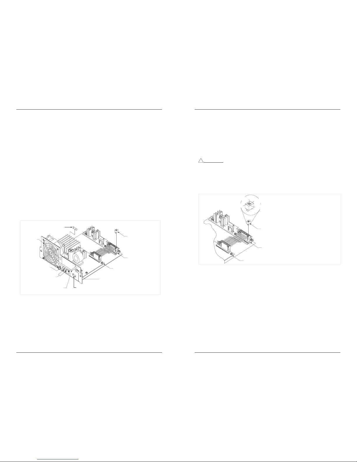
3. Set the power supply configuration switch to the desired positions. See Figure 6.
4. Slide the power supply into the installation slot as shown in Figure 7, aligning it
with the installation guides—make sure that it is fully seated in the chassis slot.
5. Re-install and tighten the two (2) 6-23 philips head screws to secure the power
supply to the chassis.
Chassis
Power-Supply
Slot Cover
6-32 Philips
Chassis
Power Supply
Guide
6-32 Philips
Figure 5: Remove Chassis Power-Supply Slot Cover
Figure 7: Power Supply Installation
Figure 6: Configuration Switch
Master
Slave
Management
Manual
CPSMP-210 48VDC and CPSMP-220 24VDC Power Supplies
Page 5

CPSMP-210 48VDC and CPSMP-220 24VDC Power Supplies
8
24-Hour Technical Support: 1-800-260-1312 -- International: 00-1-952-941-7600
Installation—continued
Power source circuit requirements
The CPSMP 210 and 220 power supplies must be connected to a Safety Extra Low
Voltage (SELV) circuit. The installer must first determine circuit characteristics; for
example, limited current, and hazardous energy levels, etc., and then install the power
supply in accordance with local and national electrical codes.
Equipment ground
WARNING: The power supply has a provision for grounding. Equipment
grounding is vital to ensure safe operation. The installer must ensure that the power
supply is properly grounded during and after installation. Failure to observe this
warning could result in an electric shock.
Disconnect requirements
WARNING: A readily accessible, suitable National Electrical Code (NEC) or
local electrical code approved disconnect device and branch-circuit protector must
be part of the building's installed wiring to accommodate permanently connected
equipment. Failure to observe this warning could result in an electric shock, even
death.
WARNING:
Ensure that the disconnect device for the external power source is
OPEN (turned OFF) before disconnecting or connecting the power leads to the
power supply. Failure to observe this warning could result in an electric shock,
even death.
CAUTION:
While installing or servicing the power supply, wear a grounding
device and observe all electrostatic discharge precautions. Failure to observe this
caution could result in damage to, or failure of the power supply.
Connecting external power
To connect the external power to the power supply:
1. Slide the power ON/OFF switch to the OFF position.
2. Make sure that the external power source is turned OFF (disconnect device open).
3. First, onnect the power source ground lead to chassis ground. See Figure 8.
4. Connect the positive DC lead to the terminal block “+.”
5. Connect the negative DC lead to the terminal block “-.”
!
!
!
!
+
-
Ex ternal P ower Cables
Power Supply Terminal Bloc
k
Figure 8: Power Supply Terminal Block and External Power Cable Connections
techsupport@transition.com -- Click the “Transition Now” link for live Web chat.
9
Connecting external power—continued
6. Power UP the external power source (disconnect device is closed).
7. Slide the power ON/OFF switch to the ON position.
8. Verify that the power supply module is functional by noting that the fan is ON and
the power LED is lit. If not, see Troubleshooting on page 13.
Redundant (failover) chassis power supply
Note: In a dual redundant power supply configuration, the fan will operate while the
power supply’s ON/OFF switch is in the OFF position. This provides extra
chassis heat exhaust when the supply is not in use in stand-by mode.
IMPORTANT:
• In a multiple power supply chassis, one power supply configuration switch must
be set to master . If both modules are set to slave neither will supply sufficient
power to the chassis.
• Power supply load sharing (configuring multiple supplies as masters in a chassis)
is not recommended (no load balancing capability).
To install and set up a second power supply for redundancy (failover):
1. Slide the power supply’s power switch to the OFF position.
2. Make sure that the external power source is turned OFF.
3 Remove and keep the two (2) 6-32 philips head screws holding the power-supply
slot cover. See Figure 9.
4. Set up the second power supply’s configuration switch. See page 5.
5. Slide the second power supply in to the chassis as shown in Figure 10.
6. Secure the power supply to the chassis with the two (2) 6-32 philips head screws.
Power-Supply Slot Cover
6-32 Philip s
6-32 Philip s
Figure 9: Chassis Power-Supply Slot Cover
Figure 10: Power Supply Installation
CPSMP-210 48VDC and CPSMP-220 24VDC Power Supplies
Page 6

CPSMP-210 48VDC and CPSMP-220 24VDC Power Supplies
10
24-Hour Technical Support: 1-800-260-1312 -- International: 00-1-952-941-7600
Maintenance
WARNING: Do not connect the power supply module to the external power
source before installing it into the chassis. Failure to observe this warning could
result an electrical shock, even death.
Replacing the power supply
Note: The power supply module can be hot swapped (i.e., swapped while the chassis
is in operation) provided that it is not connected to an external power source,
and its ON/OFF switch is in the OFF position.
To replace the power supply module:
1. Slide the ON/OFF power switch to the OFF position.
2. Make sure that the external power source is turned OFF (disconnect device open).
3. Remove the ground wire last, disconnect the external power source leads.
4. Remove and keep the two (2) 6-32 philips head screws securing the power supply
to the chassis.
5. Carefully pull the power supply from the chassis. See Figure 11.
6-32 Philip s
Configuring the power supply
To configure and install the new power supply:
1. Set up the configuration switch shown in Figure 12. See page 5 for details.
2. Slide the power supply into the chassis slot, as shown in Figure 11 above.
Figure 11: Power Supply Removal and Installation
Management
Master
Slave
Manual
Four-Position Configuration Switch
Instan t Failov er (IFO) Board
Figure 12: Power Supply configuration Switch
!
techsupport@transition.com -- Click the “Transition Now” link for live Web chat.
11
Maintenance—continued
Configuring the power supply—continued
3. Ensure that the module is firmly seated inside the chassis.
4. Re-install the two (2) 6-32 philips head screws.
5. See “Connecting external power,” (page 8) for instructions on re-connecting the
power supply to the external power source.
Replacing the fuse
To replace the fuse in the power supply:
1. Turn the power supply OFF.
2. Remove the ground wire last, disconnect the power supply module from the
external power source.
3. Remove and keep the two (2) 6-32 philips head screws that secure the module to
the chassis.
4. Carefully pull the power supply from the chassis.
5. Carefully remove the fuse from the fuse holder, shown in Figure 13.
6. Install a good fuse with the same size and rating.
7. Carefully slide the power supply back into the chassis.
8. Ensure that the module is firmly seated inside the chassis.
9. Re-install the two (2) 6-32 philips head screws to secure the power supply to the
chassis.
10. See “Connecting External Power” (page 8) for instructions on re-connecting the
external power source.
Fuse
Fuse Holder
Fuse
Terminal Block
Figure 13: Fuse Holder Containing Fuse
CPSMP-210 48VDC and CPSMP-220 24VDC Power Supplies
Page 7

CPSMP-210 48VDC and CPSMP-220 24VDC Power Supplies
12
24-Hour Technical Support: 1-800-260-1312 -- International: 00-1-952-941-7600
Technical Specification
For use with Transition Networks Model CPSMP-210, CPSMP-220, or equivalent.
Standards: FCC & CISPR Class A & B; CE Mark
Dimensions: 8.3" x 8.4" x 2.7" (211 mm x 211 mm x 69 mm)
Weight: 1 lb. (0.45 kg) approximate
Fuse: 6.3A 250 V
CPSMP-210: Power input: 48VDC (40–56VDC) @ 2.75A
(typical for a fully-loaded chassis)
Power output: 12VDC at 12.5A maximum.
Fuse: 250V, 6.3A
Inrush current 5A max
Under voltage
lockout: 40V max, 38V min
Efficiency: > 85%
Total power:
dissipation: 23W typical
CPSMP-220: Power input: 24VDC (20–30VDC) @ 5.5 Amp
(typical for a fully loaded chassis)
Fuse: 60V, 12A
Inrush current: 10A max
Under voltage:
Lockout: 20V max, 18V min
Efficiency: >75%
Total power:
dissipation: 36W typical
Power output: 12VDC at 12.5A maximum.
Operating temp: 0°C to 60°C (32°F to 140°F )
Storage temp: -20°C to 85°C (-4°F 185°F)
Humidity: 5% to 95%, non-condensing
Altitude: 0 to 10,000 feet
Warranty: Lifetime
This product specification is subject to change without further notice. For the most upto-date information, see the user’s guide for this product on-line at
www.transition.com.
techsupport@transition.com -- Click the “Transition Now” link for live Web chat.
13
Troubleshooting
If the power supply module fails or is not working properly, isolate and correct the
problem by determining the answers to the following questions and then taking the
indicated action:
1. Is the Power ON LED lit?
YES
Note: In a dual power supply chassis, make sure that one power supply’s
configuration switch is set to Master and the second set to Slave. See
“Configuring two power supplies in one chassis,” page 6.
• Contact Technical Support: US/Canada: 1-800-260-1312, International:
00-1-952-941-7600.
If the power ON LED is not lit
, check the following:
2. Is the power supply’s ON/OFF switch in the ON position? If yes, and still no
activity, slide the switch to the OFF position and move to step “3.”
3. Is the power supply module properly connected to the external power source?
a. See “Connecting external power,” page 8. If yes, move to step “b.”
b. Is the disconnect device for the external power source properly installed and
in the ON position?
- If not, set it to ON and then slide the power supply ON/OFF switch to the
ON position. If still no activity, slide the power supply switch to the OFF
position and move to step “c.”
c. Verify that the external power source voltage and current are at the proper
levels. If not, correct the problem; if they are, move to step “4.”
4. Check that the power supply’s fuse is not blown? See “Replacing the fuse,”
on page 11. If it is not: Contact Technical Support: US/Canada: 1-800-2601312, International: 00-1-952-941-7600.
CPSMP-210 48VDC and CPSMP-220 24VDC Power Supplies
Page 8

CPSMP-210 48VDC and CPSMP-220 24VDC Power Supplies
14
24-Hour Technical Support: 1-800-260-1312 -- International: 00-1-952-941-7600
Contact Us
Technical support
Technical support is available 24 hours a day.
US and Canada: 1-800-260-1312
International: 00-1-952-941-7600
Transition now
Chat live via the Web with Transition Networks Technical Support.
Log onto www.transition.com and click the Transition Now link.
Web-based seminars
Transition Networks provides seminars via live web-based training.
Log onto www.transition.com and click the Learning Center link.
E-Mail
Ask a question anytime by sending an e-mail to our technical support staff at
techsupport@transition.com
Address
Transition Networks; 6475 City West Parkway, Minneapolis, MN 55344, U.S.A.
telephone: 952-941-7600; toll free: 800-526-9267; fax: 952-941-2322
Declaration of Conformity
Name of Mfg: Transition Networks
6475 City West Parkway, Minneapolis MN 55344 U.S.A.
Model: CPSMP-210, CPSMP-220 DC Power Supply Module
Part Number(s): CPSMP-210, CPSMP-220
Regulation: EMC Directive 89/336/EEC
Purpose: To declare that the CPSMP-210 and CPSMP-220 to which this declaration
refers is in conformity with the following standards: CISPR 22: (1997) w/A1: 2000 Class
A & B; EN 55022: (1998) w/A1: 2000 & A2: 2003 Class A & B; EN 55024:1998 w/A1: 2001
I, the undersigned, hereby declare that the equipment specified above conforms to the above
Directive(s) and Standard(s).
Aug 5, 2005_____
Stephen Anderson, Vice-President of Engineering Date
techsupport@transition.com -- Click the “Transition Now” link for live Web chat.
15
Compliance Information
CISPR22/EN55022 Class A & B
CE Mark1
FCC regulations
This equipment has been tested and found to comply with the limits for a Class A & B digital
device, pursuant to part 15 of the FCC rules. These limits are designed to provide reasonable
protection against harmful interference when the equipment is operated in a commercial
environment. This equipment generates, uses, and can radiate radio frequency energy and, if not
installed and used in accordance with the instruction manual, may cause harmful interference to
radio communications. Operation of this equipment in a residential area is likely to cause harmful
interference, in which case the user will be required to correct the interference at the user's own
expense.
Canadian regulations
This digital apparatus does not exceed the Class A&B limits for radio noise for digital apparatus set
out on the radio interference regulations of the Canadian Department of Communications.
Le présent appareil numérique n'émet pas de bruits radioélectriques dépassant les limites applicables
aux appareils numériques de la Class A & B prescrites dans le Règlement sur le brouillage
radioélectrique édicté par le ministère des Communications du Canada.
CPSMP-210 48VDC and CPSMP-220 24VDC Power Supplies
Page 9

Trademark notice
All trademarks and registered trademarks are the property of their respective owners.
Copyright restrictions
© 2000, 2004-2005 Transition Networks.
All rights reserved. No part of this work may be reproduced or used in any form or by any means—
graphic, electronic, or mechanical—without written permission from Transition Networks.
Printed in the U.S.A. 33187.C
CPSMP-210 48VDC and CPSMP-220 24VDC Power Supplies
 Loading...