

Page 1
Transition Networks CPSMM-200 Dual-Slot Master Management Module enables
network management of a single PointSystem™ chassis (CPSMC0800-100,
CPSMC13xx-100, CPSMC18xx-xxx, and CPSMC19xx-100) and any installed media
converter slide-in-modules.
The CPSMM-200 includes Transition Networks CPSMM100 Firmware embedded
in the module, which can be accessed via the DB-9 serial port or the 10Base-T RJ45 Ethernet port.
In addition, the CPSMM-200 has two RJ-45 ports (“in” and “out”) to accommodate
stacking multiple PointSystem™ chassis. Multiple chassis can be “cascaded” in
this manner with a CPSMM-210 Single-Slot Expansion Management Module
installed in each subsequent chassis in the stack.
Installation . . . . . . . . . . . . . . . . . .4
Network Management . . . . . . . . .6
Operation . . . . . . . . . . . . . . . . . . .7
Technical Specifications . . . . . . . .9
Troubleshooting . . . . . . . . . . . . .10
Compliance Information . . . . . . .12
User’s Guide
CPSMM-200 - Dual-Slot Master Management Module
CPSMM-210 - Single-Slot Expansion Management Module
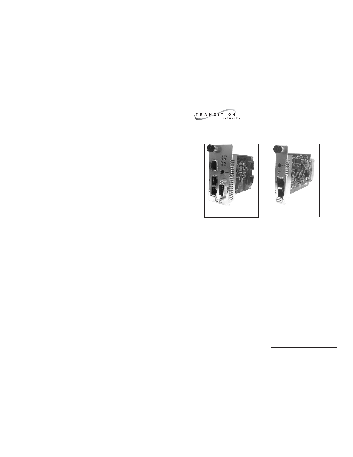
CPSMM-200
Dual-Slot Master
CPSMM-210
Single-Slot Expansion
Page 2
CPSMM-200 / CPSMM-210
2
24-hour Technical Support: 1-800-260-1312 International: 00-1-952-941-7600
CPSMM-200 Dual-Slot Master Management Module
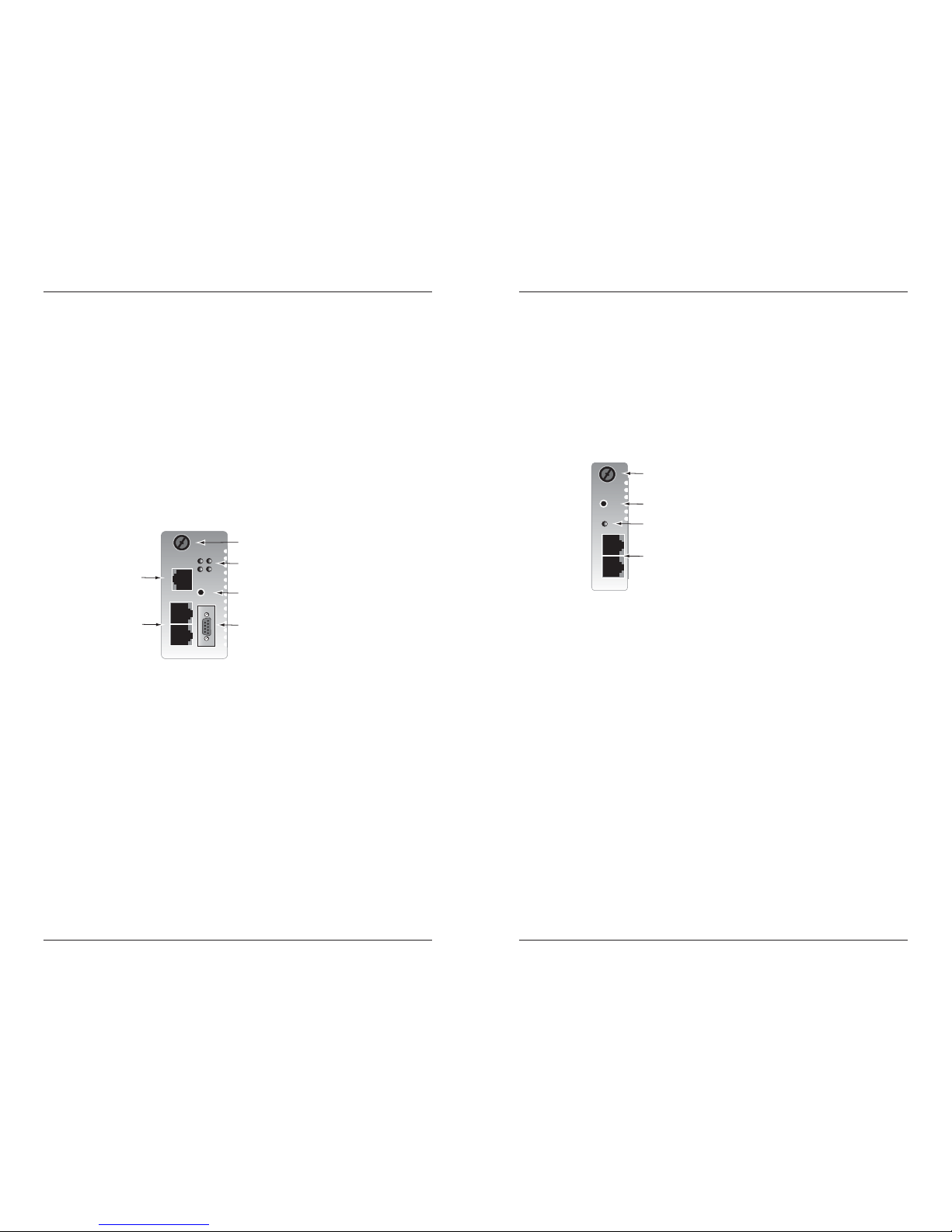
The figure below illustrates the components of the CPSMM-200 management
module:
•A panel fastener screw that secures the management module to the
Pointsystem™ chassis.
• PWR (power), LNK (link), RX (receive) and TX (transmit) LED indicators.
•A reset switch, which resets ONLY the CPSMM-200 management module
(not the chassis in which it is installed).
• A 10Base-T RJ-45 Ethernet port, through which the management module
communicates, using the Ethernet network, with a remote Network
management Station (NMS) or with a Telnet connection
•A DB-9 serial port, through which the management module
communicates with the command-line interface.
• Two (2) RJ-45 cascade ports, through which multiple Pointsystem™
chassis are connected (see page 4).
RX
TX
LNK
PWR
CPSMM200
10BASE-T
IN
OUT
Reset
SERIAL
LEDs
Panel Fastener Screw
Reset Switch
DB-9 Serial Port
RJ-45
Ethernet
Port
RJ-45
Cascade
Ports
CPSMM-200
dual-slot master
management module
techsupport@transition.com -- Click the “Transition Now” link for a live Web chat.
3
CPSMM-210 Single-Slot Expansion Management Module
The figure below illustrates the components of the CPSMM-210 expansion
management module:
•A panel fastener screw that secures the management module to the
Pointsystem™ chassis.
•A POWER LED indicator.
•A reset switch, which resets ONLY the CPSMM-210 management module
(not the chassis in which it is installed).
• Two (2) RJ-45 cascade ports, through which multiple Pointsystem™
chassis are connected (see page 4).
Application CD
The enclosed application CD contains:
1. CPSMM100 Firmware, which includes:
• a Command-Line Interface (CLI),
• a Telnet server,
• a Web browser, and
• an SNMP Agent.
2. FocalPoint™ 2.0 Management Application, which can be used to
monitor and control the PointSystem™ chassis from a remote location.
3. A User’s Guide, which describes in detail how to use both the
CPSMM100 Firmware and the FocalPoint™ 2.0 management application.
Power
CPSMM210
IN
OUT
Reset
Reset Switch
Panel Fastener Scre
w
LED
RJ-45
Cascade
Ports
CPSMM-210
single-slot expansion
management module
Page 3
CPSMM-200 / CPSMM-210
4
24-hour Technical Support: 1-800-260-1312 International: 00-1-952-941-7600
Installation
Single Chassis Option
The CPSMM-200 management module is designed be installed into a
Transition Networks PointSystem™ chassis to enables network management
of any media converter slide-in-modules installed in the chassis. The
following chassis are available:
• CPSMC0800-100, 8-slot PointSystem™ chassis
• CPSMC13xx-100, 13-slot PointSystem™ chassis
• CPSMC18xx-xxx, 18-slot PointSystem™ chassis
• CPSMC19xx-100, 19-slot PointSystem™ chassis
10BASE-T
INPORT
OUTPORT
12C
12C-1TERM
INIT
RX
TX
LNK
PWR
RESET
The CPSMM-200 management module is installed
in one of the Transition Network PointSystemTM chassis.
(Configuration for the 13-slot, 18-slot, or 19-slot chassis is shown.)
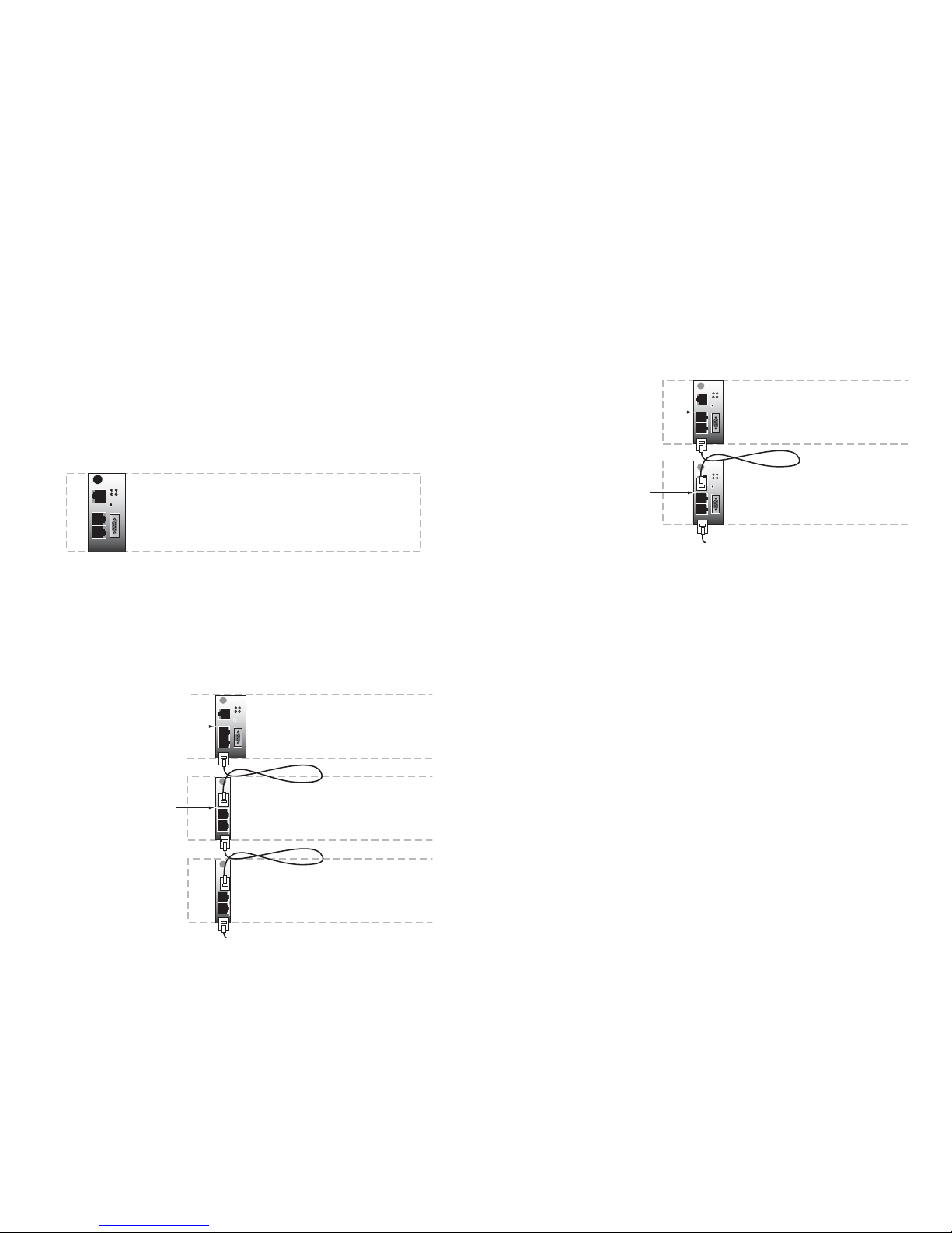
Cascade Option
The management module cascade option allows the network administrator to
connect up to eight (8) PointSystem™ chassis into one manageable stack,
providing a single management source for up to 143 conversion devices.
To create the cascade option, the CPSMM-200 dual-slot master management
module is installed in the first chassis in the series. The CPSMM-210 singleslot expansion management module is installed in each subsequent chassis.
Pwr
RESET
12C
12C-1
TERM
INIT
Pwr
RESET
12C
12C-1
TERM
INIT
10BASE-T
INPORT
MCCM10
MGMT MASTER
RX
TX
LNK
PWR
OUTPORT
RESET
12C
12C-1TERM
INIT
DB-9
The CPSMM-200
management module is
installed in the first
chassis in the series
The CPSMM-210
management module is
installed in each
subsequent chassis
Installation -- Continued
Redundant Management Option
An alternative setup involves installing two CPSMC-200 dual-slot master
management modules into two adjacent chassis for redundant management.
Redundant management can also be set up with the two CPSMM-200
modules installed in the same chassis.
In this set-up, the two modules auto-negotiate; where one is the primary
module while the other is in stand-by mode. If the primary module fails, the
stand-by module automatically takes over and manages the network.
Replacing the CPSMM-200
The CPSMM-200 can be hot-swapped, that is, it can be replaced while the
PointSystem™ chassis is powered. However, please note that:
• If there are two management modules installed in the same network, the
stand-by module will continue to manage the network while the primary
module is replaced. Also, the stand-by module will retain all network
settings.
• If there is only one management module installed, all SNMP management
operations will cease once the module is removed. The newly installed
management module must be reconfigured to resume network
management.
Replacing the CPSMM-210
The CPSMM-210 can also be hot-swapped. However, unlike the CPSMM200, the network’s management settings do not need to be reconfigured if the
CPSMM-210 is replaced.
For more information on installing or replacing the management modules, see
the user’s guide for the chassis in which the module will be installed. The
chassis manuals can be found on the Web at: www.transition.com.
techsupport@transition.com -- Click the “Transition Now” link for a live Web chat.
5
10BASE-T
INPORT
MCCM10
MGMT MASTER
RX
TX
LNK
PWR
OUTPORT
RESET
12C
12C-1TERM
INIT
DB-9
The CPSMM-200
management module is
installed in the first
chassis in the series
Another CPSMM-200
managment module is
installed in the next
chassis as a backup
10BASE-T
INPORT
MCCM10
MGMT MASTER
RX
TX
LNK
PWR
OUTPORT
RESET
12C
12C-1TERM
INIT
DB-9
Page 4

CPSMM-200 / CPSMM-210
6
24-hour Technical Support: 1-800-260-1312 International: 00-1-952-941-7600
Network Management
CPSMM100 Firmware
The Transition Networks CPSMM100 Firmware is embedded in the CPSMM200 management module. The firmware includes:
•a Command-Line Interface (CLI),
•a Telnet server,
•a Web browser, and
• an SNMP agent.
Each of these applications can be accessed either through the module’s DB-9
serial port or RJ-45 Ethernet port, which allows the network administrator to
monitor and control the network from an attached terminal or from a remote
location.
FocalPoint™ 2.0 Management Application
Transition Networks FocalPoint™ 2.0 management application can be
installed in a networked computer to provide a graphical user interface to
monitor the network. The version on the enclosed CD supports all features of
the enclosed CPSMM100 Firmware as well as all Transition Networks slide-inmodules that are available at the time the CD was produced.
NOTE: For detailed information on how to:
• Set up and configure a network using the CPSMM100 Firmware.
• Use the Command-Line Interface, Telnet server, or Web browser.
• Install and use the FocalPoint™ 2.0 management application.
See the FocalPoint™ 2.0 Management Application and CPSMM100 Firmware
User’s Guide on the enclosed application CD. It can also be viewed on the
Transition Networks website at: www.transition.com.
Operation
Reset Switch
Both the CPSMM-200 and the CPSMM-210 have a reset switch which resets
only the management module (not the entire chassis in which the module has
been installed).
techsupport@transition.com -- Click the “Transition Now” link for a live Web chat.
7
Operation -- Continued
LED Indicators
Both the CPSMM-200 and the CPSMM-210 have a power LED:
PWR On = The management module is receiving power from the chassis.
CPSMM-200 CPSMM-210
The CPSMM-200 management module also has three additional status LEDs,
which are used to monitor the operation of the management module in the
network.
LNK On = A link has been established via the DB-9 serial port or
the RJ-45 Ethernet port.
RX Flashing = The management module is receiving data via the DB-
9 serial port or the RJ-45 Ethernet port.
TX Flashing = The management module is transmitting data via the
DB-9 serial port or the RJ-45 Ethernet port.
RX
TX
LNK
PWR
CPSMM200
10BASE-T
IN
OUT
Reset
SERIAL
LEDs
Reset
Switch
Power
CPSMM210
IN
OUT
Reset
Reset
Switch
LED
Page 5

CPSMM-200 / CPSMM-210
8
24-hour Technical Support: 1-800-260-1312 International: 00-1-952-941-7600
Operation -- Continued
LED Indicators
Both the CPSMM-200 and CPSMM-210 have four LEDs embedded in the
cascade ports.
CPSMM-200 CPSMM-210
IN - LED 1 (amber) Flashes once when the management module is
powered on and indicates that the BIA (burned in
address) has gone through the read cycle.
IN - LED 2 (green) Flashes when a signal is being received or transmitted
via either RJ-45 cascade port. This LED also flashes if
there is network activity on chassis’ backplane.
OUT - LED 1 (amber) Remains on if the module is the only management
module in the network, or if it is the primary
management module in a network with two
management modules.
Remains off if the module is the secondary
management module in a network with two
management modules.
OUT - LED 2 (green) Remains on when the processor inside the module has
started and is initialized.
Power
CPSMM210
IN
OUT
Reset
RX
TX
LNK
PWR
CPSMM200
10BASE-T
IN
OUT
Reset
SERIAL
LED 2
LED 1
LED 2
LED 1
LED 2
LED 1
LED 2
LED 1
techsupport@transition.com -- Click the “Transition Now” link for a live Web chat.
9
Technical Specification
For use with Transition Networks models CPSMM-200, CPSMM-210, or
equivalent.
Standards CISPR 22:1993; Class A & B; CE Mark
CPSMM-200:
Dimensions 3.4” x 1.72” x 5.0” (86 mm x 44 mm x 127 mm)
Shipping Weight 6 oz. (181 g) (approximate)
Power Consumption 3.3 Watts.
MTBF 144,000 hours (MIL217F2 V5.0) (MIL-HDBK-217F)
713,000 hours (Bellcore7 V5.0)
CPSMM-210:
Dimensions 3.4” x 0.86” x 5.0” (86 mm x 22 mm x 127 mm)
Shipping Weight 3 oz. (91 g) (approximate)
Power Consumption 2.4 Watts.
MTBF 343,000 hours (MIL217F2 V5.0) (MIL-HDBK-217F)
1,145,000 hours (Bellcore7 V5.0)
Environment Tmra*: 0 to 60°C (32 to 140°F )
Storage Temp: -20 to 85°C (-4 to 185°F)
Humidity: 10 to 90%, non condensing
Altitude: 0 to 10,000 feet
Warranty Lifetime
*Manufacturer’s rated ambient temperature: Tmra range for these management
modules depend on the physical characteristics and the installation configuration
of the Transition Networks PointSystem™ chassis in which the modules will be
installed. See the user’s guide for the chassis in which these modules will be
installed for temperature-related installation constraints.
The information in this user’s guide is subject to change. The most up-to-date
revision of the CPSMM-200-210 user’s guide can be viewed at:
www.transition.com.
Page 6

Troubleshooting
1. Press the Reset button on the management module. Does the
fault resolve itself?
NO
• Proceed to step 2.
2. Is the “Power” LED illuminated?
NO
• Is the management module inserted properly into the chassis?
• Is the chassis properly connected to the external power source.
• Contact Technical Support: US/Canada: 1-800-260-1312,
International: 00-1-952-941-7600.
YES
• Proceed to step 3.
3. Is the “LNK” (link) LED illuminated?
NO
• If the DB-9 serial port is being used for data transmission, check it for
proper connection.
• If the RJ-45 Ethernet port is being used for data transmission, check it
for proper connection.
• Contact Technical Support: US/Canada: 1-800-260-1312,
International: 00-1-952-941-7600.
YES
• Proceed to step 4.
4. Is the “IN - LED 1” LED illuminated?
YES
• The BIA (burned in address) has not gone through the read cycle.
• Contact Technical Support: US/Canada: 1-800-260-1312,
International: 00-1-952-941-7600 .
NO
• Proceed to step 5.
5. Is the “IN-LED 2” LED illuminated?
NO
• If there is no network activity, proceed to step 6.
• Check the RJ-45 cascade cable(s) for proper connection.
• Contact Technical Support: US/Canada: 1-800-260-1312,
International: 00-1-952-941-7600 .
YES
• Proceed to step 6.
CPSMM-200 / CPSMM-210
10
24-hour Technical Support: 1-800-260-1312 International: 00-1-952-941-7600 techsupport@transition.com -- Click the “Transition Now” link for a live Web chat.
11
Declaration of Conformity
Name of Mfg: Transition Networks
6475 City West Parkway, Minneapolis MN 55344 USA
Model: CPSMM-200 Dual-Slot Master Management Module
CPSMM-210 Single-Slot Expansion Management Module
Part Number(s): CPSMM-200, CPSMM-210
Regulation: EMC Directive 89/336/EEC
Purpose: To declare that the
CPSMM-200 and CPSMM-210
to which this
declaration refers are in conformity with the following standards.
CISPR 22:1993; EN 55022:1994, A1:1995, A2:1997; Class A & B; FCC Part 15
Subpart B; EN 55024:1998; EN 61000-3-2:1995; EN 61000-3-3:1005
I, the undersigned, hereby declare that the equipment specified above conforms to the above
Directive(s) and Standard(s).
July 8, 2001
Stephen Anderson, Vice-President of Engineering Date
Troubleshooting -- Continued
6. Is the “OUT-LED 2” LED illuminated?
NO
• The processor inside the management module has not initialized.
• Contact Technical Support: US/Canada: 1-800-260-1312,
International: 00-1-952-941-7600 .
NOTE: To Isolate faults involving data transmission, Please see the
“Troubleshooting” section of the FocalPoint™ Management Application
& CPSMM100 Firmware User’s Guide on the enclosed application CD.
It can also be viewed on the Transition Networks website at:
www.transition.com.
Page 7

Trademark Notice
All trademarks and registered trademarks are the property of their respective owners.
Copyright Restrictions
© 2001, 2004-2005 Transition Networks.
All rights reserved. No part of this work may be reproduced or used in any form or by any
means - graphic, electronic, or mechanical - without written permission from Transition
Networks.
Printed in the U.S.A.
33189.G
Compliance Information
CISPR22/EN55022 Class A & B + EN55024
CE Mark
FCC Regulations
This equipment has been tested and found to comply with the limits for a Class A & B digital
device, pursuant to part 15 of the FCC rules. These limits are designed to provide reasonable
protection against harmful interference when the equipment is operated in a commercial
environment. This equipment generates, uses, and can radiate radio frequency energy and, if
not installed and used in accordance with the instruction manual, may cause harmful
interference to radio communications. Operation of this equipment in a residential area is
likely to cause harmful interference, in which case the user will be required to correct the
interference at the user's own expense.
Canadian Regulations
This digital apparatus does not exceed the Class A & B limits for radio noise for digital
apparatus set out on the radio interference regulations of the Canadian Department of
Communications.
Le présent appareil numérique n'émet pas de bruits radioélectriques dépassant les limites
applicables aux appareils numériques de la Class A & B prescrites dans le Règlement sur le
brouillage radioélectrique édicté par le ministère des Communications du Canada.
CAUTION: RJ connectors are NOT INTENDED FOR CONNECTION TO THE
PUBLIC TELEPHONE NETWORK. Failure to observe this caution could result in
damage to the public telephone network.
Der Anschluss dieses Gerätes an ein öffentlickes Telekommunikationsnetz in den EGMitgliedstaaten verstösst gegen die jeweligen einzelstaatlichen Gesetze zur Anwendung der
Richtlinie 91/263/EWG zur Angleichung der Rechtsvorschriften der Mitgliedstaaten über
Telekommunikationsendeinrichtungen einschliesslich der gegenseitigen Anerkennung ihrer
Konformität.
Contact Transition Networks
Technical support is available 24 hours a day.
US and Canada: 1-800-260-1312 International: 00-1-952-941-7600
Chat live via the Web with Transition Networks Technical Support.
Log onto www.transition.com and click the Transition Now link.
Transition Networks provides seminars via live web-based training.
Log onto www.transition.com and click the Learning Center link.
Send an e-mail anytime to our technical support staff at: techsupport@transition.com
Transition Networks
6475 City West Pkwy
Minneapolis, MN 55344, USA
telephone: 952-941-7600
toll free: 800-526-9267
fax: 952-941-2322
 Loading...