

Transition Networks CMEFG1014-100, CMEFG1013-110, CMEFG1029-100, CMEFG1014-110, CMEFG1029-101 User Manual
...Page 1
User’s Guide
CMEFG10xx-1xx - Slide-in-Module
SMEFG10xx-1xx - Stand-Alone
Media Converters
•
Copper to Fiber Gigabit Ethernet
• 10/100/1000Base-T to 1000Base-SX/LX
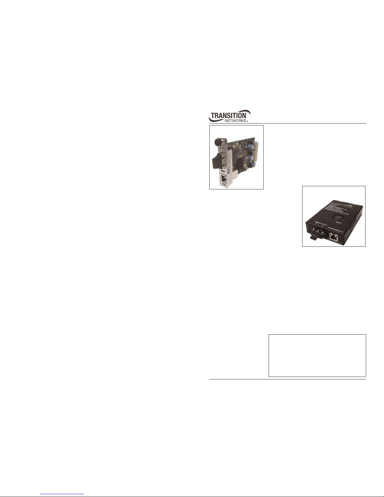
CMEFG10xx-1xx
(local)
Remote management
The CMEFG10xx-1xx (chassis version) is designed to remotely manage the
SMEFG10xx-1xx (the stand-alone version) or another CMEFG10xx-1xx per IEEE
802.3ah™:2004 standard.
For example, a local CMEFG1011-100 converter installed in a managed Transition
Networks PointSystem™ chassis is connected, via fiber, to a remote SMEFG1011100 converter.
Network management
The SNMP section lists commands for monitoring and managing a networked
media converter at a remote location. The CMEFG10xx-2xx and SMEFG10xx-2xx
devices are supported by 050xxxxx and later revisions of the management agent.
Please download the latest management firmware at www.transition.com.
Transition Networks CMEFG10xx-1xx and
SMEFG10xx-1xx series gigabit Ethernet media
converters connect 10/100/1000Base-T
shielded or unshielded twisted-pair copper
cable to 1000Base-SX/LX fiber-optic cable.
The media converters are designed to be
installed in pairs where the CMEFG10xx-1xx
is the local media converter and the
SMEFG10xx-1xx is the remote media
converter.
SMEFG10xx-1xx
(remote)
Installation . . . . . . . . . . . . . . . . . . . . . . . . . .5
Operation . . . . . . . . . . . . . . . . . . . . . . . . . . .7
Diagnostic Management Interface (DMI) . . . .14
Cable Specification . . . . . . . . . . . . . . . . . . . .15
Technical Specifications . . . . . . . . . . . . . . . .18
Troubleshooting . . . . . . . . . . . . . . . . . . . . . .19
Contact Us . . . . . . . . . . . . . . . . . . . . . . . . . .22
Compliance . . . . . . . . . . . . . . . . . . . . . . . . .23
Page 2
2
CMEFG10xx-1xx / SMEFG10xx-1xx
24-hour Technical Support: 1-800-260-1312 International: 00-1-952-941-7600
Part Number Port 1 - Copper
10/100/1000Base-T
Port 2 - Single Fiber-Optic
1000Base-BX-U/D, single mode
CMEFG1029-100
SMEFG1029-100
RJ-45
100m (328 ft)
SC, 1310 nm (TX) / 1490 nm (RX)
20 km (12.4 miles)
CMEFG1029-101
SMEFG1029-101
RJ-45,
100m (328 ft)
SC, 1490 nm (TX) / 1310 nm (RX)
20 km (12.4 miles)
CMEFG1029-102
SMEFG1029-102
RJ-45
100m (328 ft)
SC, 1310 nm (TX) / 1490 nm (RX)
40 km (24.9 miles)
CMEFG1029-103
SMEFG1029-103
RJ-45
100m (328 ft)
SC, 1490 nm (TX) / 1310 nm (RX)
40 km (24.9 miles)
TX = transmit, RX = receive
Note: The distances listed are the typical maximum cable distance. Actual
distance is dependent upon the physical characteristics of the network.
Install a CMEFG1029-100 (local) with a SMEFG1029-101 (remote).
Or install a CMEFG1029-101 (local) with a SMEFG1029-100 (remote).
Install a CMEFG1029-102 (local) with a SMEFG1029-103 (remote).
Or install a CMEFG1029-103 (local) with a SMEFG1029-102 (remote).
Part Number Port 1 - Copper
10/100/1000Base-T
Port 2 - Duplex Fiber-Optic
CMEFG1013-100
SMEFG1013-100
RJ-45
100m (328 ft)
SC, 1000Base-SX, 850 nm multimode
220 m (720 ft)
CMEFG1014-100
SMEFG1014-100
RJ-45
100m (328 ft)
SC, 1000Base-LX, 1310 nm Single Mode
10 km (6.2 miles)
CMEFG1015-100
SMEFG1015-100
RJ-45
100m (328 ft)
SC, 1000Base-LX, 1310 nm single mode
25 km (15.5 miles)
CMEFG1017-100
SMEFG1017-100
RJ-45
100m (328 ft)
SC, 1000Base-LX, 1550 nm single mode
65 km (40.4 miles)
CMEFG1035-100
SMEFG1035-100
RJ-45
100m (328 ft)
SC, 1000Base-LX, 1550 nm single mode
125 km (77.6 miles)
Standard Models (-10x)
The standard models (listed below) perform as described in the user’s guide with
one exception: These models do not include DMI functionality.
The standard models also include single mode, single fiber models (listed below.)
techsupport@transition.com -- Click the “Transition Now” link for a live Web chat.
3
Part Number Port 1 - Copper
10/100/1000Base-T
CMEFG1029-110
SMEFG1029-110
RJ-45
100m (328 ft)
SC, 1310 nm (TX) / 1490 nm (RX)
20 km (12.4 miles)
CMEFG1029-111
SMEFG1029-111
RJ-45,
100m (328 ft)
SC, 1490 nm (TX) / 1310 nm (RX)
20 km (12.4 miles)
CMEFG1029-112
SMEFG1029-112
RJ-45
100m (328 ft)
SC, 1310 nm (TX) / 1490 nm (RX)
40 km (24.9 miles)
CMEFG1029-113
SMEFG1029-113
RJ-45
100m (328 ft)
SC, 1490 nm (TX) / 1310 nm (RX)
40 km (24.9 miles)
TX = transmit, RX = receive
Note: The distances listed are the typical maximum cable distance. Actual distance
is dependent upon the physical characteristics of the network.
Install a CMEFG1029-112 (local) with a SMEFG1029-113 (remote).
Or install a CMEFG1029-113 (local) with a SMEFG1029-112 (remote).
Part Number Port 1 - Copper
10/100/1000Base-T
Port 2 - Duplex Fiber-Optic
CMEFG1013-110
SMEFG1013-110
RJ-45
100m (328 ft)
SC, 1000Base-SX, 850 nm multimode
220 m (720 ft)
CMEFG1014-110
SMEFG1014-110
RJ-45
100m (328 ft)
SC, 1000Base-LX-10, 1310 nm singlemode
10 km (6.2 miles)
CMEFG1015-110
SMEFG1015-110
RJ-45
100m (328 ft)
SC, 1000Base-LX, 1310 nm single mode
25 km (15.5 miles)
The DMI models also include single mode, single fiber models listed below.
DMI Models (-11x)
The Diagnostic Monitoring Interface (DMI) models (listed below) allow diagnosing
problems within the network. These devices have four functions:
• Transmit power
• Receive power
• Transmit bias current
• Temperature
Within each function, the device will send a trap (i.e., error) whenever a high or
low warning event or a high or low alarm event occurs (for a total of 16 traps).
In addition, if both the local and remote media converters are DMI models, the
device will distinguish whether the trap event is from a local or a remote device.
Install a CMEFG1029-110 (local) with a SMEFG1029-111 (remote).
Or install a CMEFG1029-111 (local) with a SMEFG1029-110 (remote).
Port 2 - Single Fiber-Optic
1000Base-BX-U/D, single mode
Page 3
4
CMEFG10xx-1xx / SMEFG10xx-1xx
24-hour Technical Support: 1-800-260-1312 International: 00-1-952-941-7600
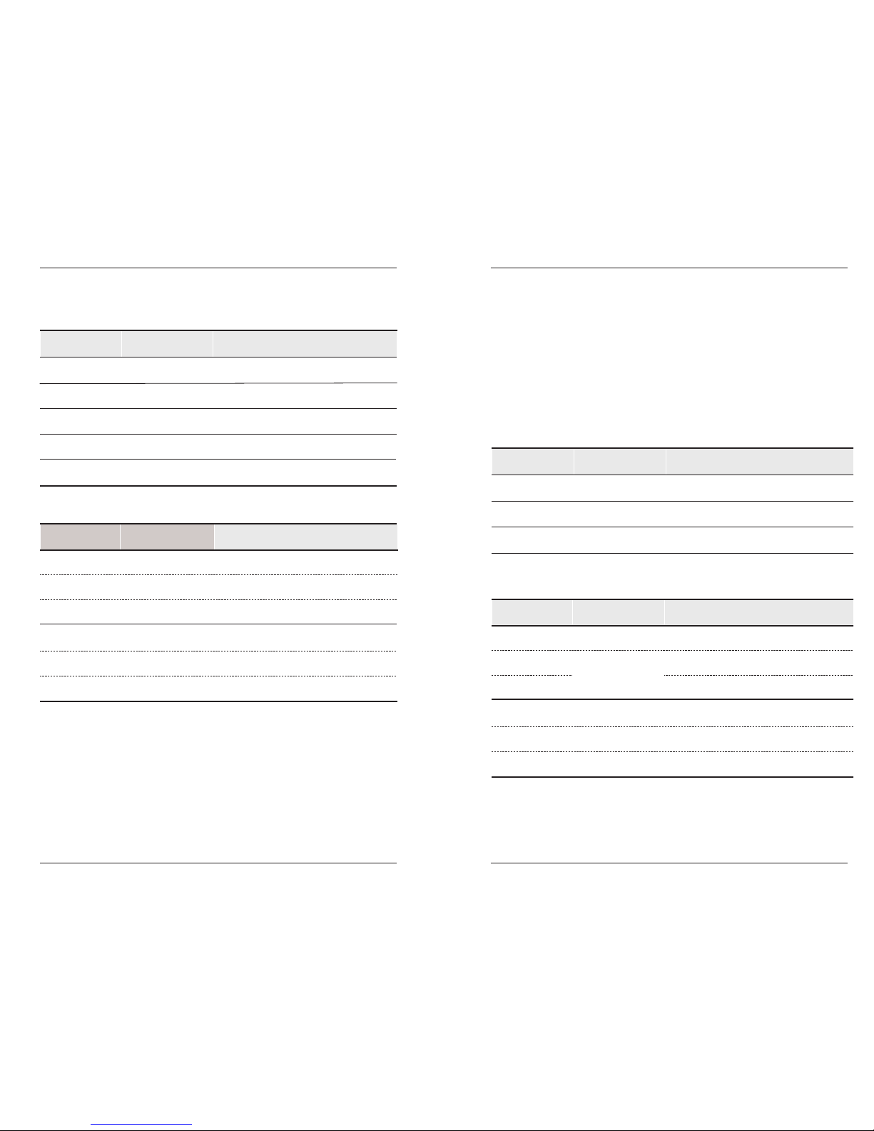
Stand-Alone Media Converter
• Copper to Fiber
• 10/100/1000Base-TX to 1000Base-SX/LX
• Small Form Fact Pluggable (SFP) Fiber Port
Transition Networks SMEFG1040-1xx series
media converters connect 10Base-TX, 100BaseTX, or 1000Base-TX twisted-pair copper cable to
1000Base-SX or 1000Base-LX fiber cable.
The SMEFG1040-10x has one copper port and
one SFP port.
SMEFG1040-1xx
*Typical maximum cable distance. Actual distance is dependent upon the physical
characteristics of the network.
Note: Third-party Multi-Source Agreement (MSA) compliant Small Form Factor
Pluggables (SFPs) can also be used in the SFMFF1040-1xx device.
The following DMI supported SFP transceiver modules are compatible with the
SFMFF1040-1xx converter and are available from Transition Networks
(sold separately).
Part Number Duplex Fiber-Optic Port 2
TN-SFP-SX
LC, 1000Base-SX, 850 nm multimode, 220-550 mm (720-1804 ft)*
TN-SFP-LX1 LC, 1000Base-LX, 1310 nm single mode, 10 km (6.2 miles)*
TN-SFP-LX3 LC, 1000Base-LX, 1310 nm single mode, 30 km (18.8 miles)*
TN-SFP-LX5 LC, 1000Base-LX, 1550 nm single mode, 50 km (31.2 miles)*
TN-SFP-LX8 LC, 1000Base-LX, 1550 nm single mode, 80 km (50.0 miles)*
Copper Port 1: 10/100/1000-Base-TX
RJ-45 100 m (328 ft)
CMEFG1040-1xx
Slide-in-Module Media Converter
• Copper to Fiber
• 10/100/1000Base-TX to 1000Base-SX/LX
• Small Form Fact Pluggable (SFP) Fiber Port
Transition Networks CMEFG1040-1xx series media
converters, designed to be installed in a
PointSystem™ chassis connect 10Base-TX,
100Base-TX, or 1000Base-TX twisted-pair copper
cable to 1000Base-SX or 1000Base-LX fiber cable. It
has one copper port and one SFP port.
Part Numbers CMEFG1040-1xx and SMEFG1040-1xx
techsupport@transition.com -- Click the “Transition Now” link for a live Web chat.
5
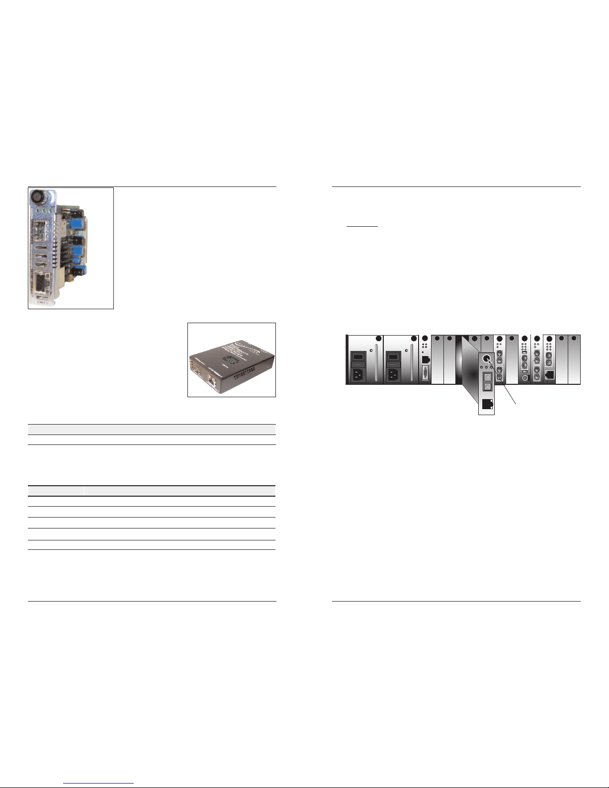
Installation
Install the CMEFG10xx-10x
CAUTION: Wear a grounding device and observe electrostatic discharge
precautions when installing the CMEFG10xx-1xx media converter in the
PointSystem™ chassis. Failure to observe this caution could result in damage
to, and subsequent failure of the CMEFG10xx-1xx media converter.
To install the CMEFG10xx-1xx media converter slide-in-module:
1. Locate an empty installation slot on the PointSystem™ chassis.
2. Carefully insert the slide-in-module into the slot, aligning the module
with the slot guides.
3. Ensure that the module is firmly seated against the back of the chassis.
4. Push in and rotate the panel-fastener screw
CFMFF100
CFMFF100
CETCF100
CFETF100
SPD
PWR
FRX
CRX
FLNK
CLNK
100BASE-TX
RX
TX
100BASE-FX
Link Alert
E
D
0
50½
LA
PWR
RXF
RXC
LNK
COL
10BASE-2
10BASE-FL
LKS
PWR
LKM
LKS
PWR
LKM
Multimode
Singlemode
TX
RX
TX
RX
Multimode
Singlemode
TX
RX
TX
RX
I
0
TERM
INIT
RX
TX
LNK
PWR
CPSMM120
SERIAL
10BASE-T
R
E
S
E
T
I
0
PWR
10/100/1000Base-T
RX
TX
1000Base-SX/LX
FD LACT
Panel Fastener Screw
Note: The CMEFG10xx.1xx is not designed for use in the Transition Networks
single-slot chassis. It will work in all other Transition Networks chassis.
Page 4
6
CMEFG10xx-1xx / SMEFG10xx-1xx
24-hour Technical Support: 1-800-260-1312 International: 00-1-952-941-7600
Installation -- Continued
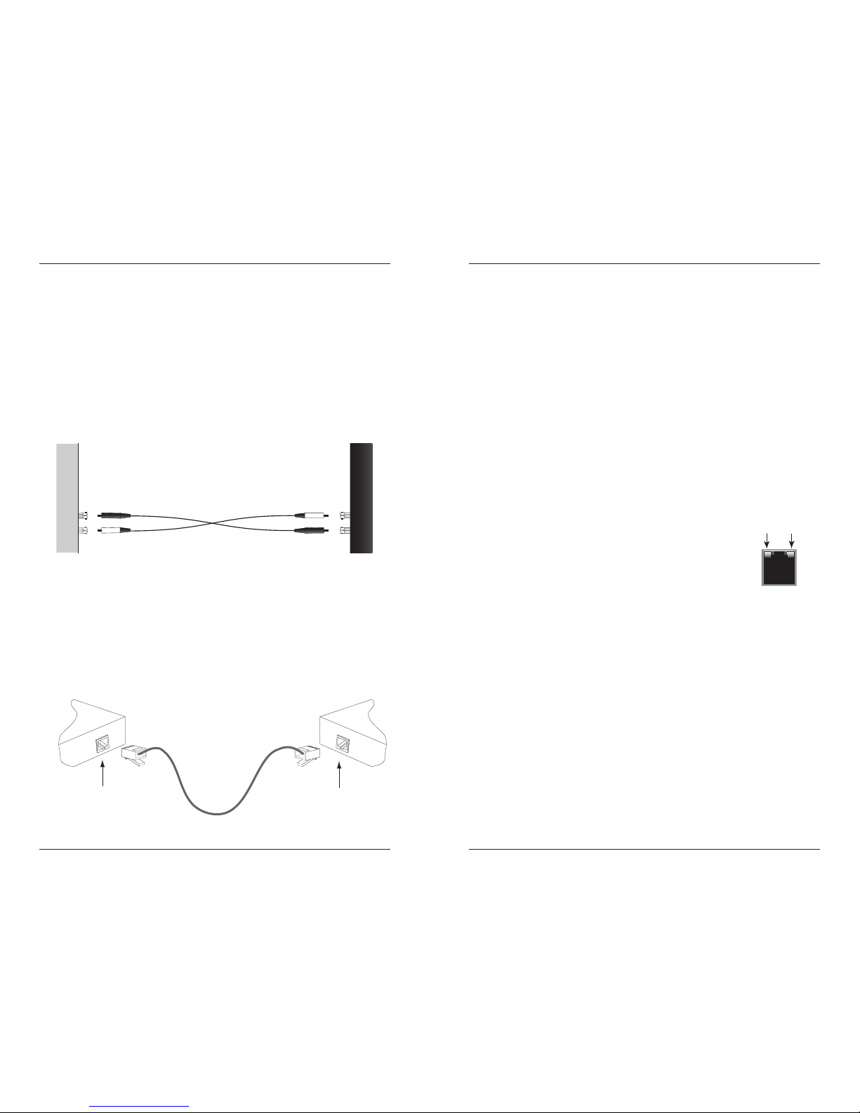
Install the fiber cable
1. Locate or build 1000Base-SX/LX compliant fiber cable with male, twostranded TX to RX connectors installed at both ends.
2. Connect the fiber cables to the CMEFG10xx-1xx media converter as
described:
• Connect the male TX cable connector to the female TX connector.
• Connect the male RX cable connector to the female RX connector.
3. Connect the fiber cables to the SMEFG10xx-1xx media converter as
described:
• Connect the male TX cable connector to the female RX connector.
• Connect the male RX cable connector to the female TX connector.
Connect the fiber cable to
the local CMEFG10xx-2xx
media converter as shown.
Connect the fiber cable to
the remote SMEFG10xx-2xx
media converter as shown
RX
TX
RX
TX
Install the copper cable
1. Locate or build 10, 100, or 1000Base-T compliant copper cables with
male, RJ-45 connectors installed at both ends.
2. Connect the RJ-45 connector at one end of the cable to the media
converter’s 10/100/1000Base-T RJ-45 port.
3. Connect the RJ-45 connector at the other end of the cable to the 10, 100,
or 1000Base-T RJ-45 port on the other device (switch, workstation, etc.).
Note: The AutoCross feature allows the use of either straight-through or
crossover configuration cables.
RJ-45 port
on the other device
(switch, work station, etc.)
RJ-45 port
on the media
converter
techsupport@transition.com -- Click the “Transition Now” link for a live Web chat.
7
Operation
Status LEDs
The CMEFG10xx-1xx and SMEFG10xx-1xx series
media converters are designed to operate without user
intervention. Use the status LEDs to monitor the media
converter operation in the network.
Copper status LEDs
The status LEDs for the copper connection are integrated into the RJ-45 port.
These LEDs are not labeled on the media converter. Refer to the drawing to
the right for their locations.
Duplex/
Link Yellow A link in half-duplex mode has been established
for the copper connection.
Flashing Yellow The copper connection is transmitting/receiving
data in half-duplex mode.
Green A link in full-duplex mode has been established
for the copper connection.
Flashing Green The copper connection is transmitting/receiving
data in full-duplex mode.
Speed OFF 10 Mb/s operation.
Yellow 100 Mb/s operation.
Green 1000 Mb/s operation.
Installation -- Continued
Powering the CMEFG10xx-1xx converter
The CMEFG10xx-1xx slide-In-module is powered through the Transition
Networks PointSystem™ chassis.
Powering the SMEFG10xx-1xx converter
To power the SMEFG10xx-1xx media converter:
1. Connect the barrel connector on the power adapter cord to the media
converter’s power port (located on the back of the media converter).
2. Connect the power adapter plug to AC power.
3. Verify that the media converter has powered UP: the LED power
indicator light will be ON.
For DC power, consult the user’s guide for the Transition Networks DC
external power supply (P/N SPS1872-xx ) for powering the media converter.
Speed
10/100/1000Base-T
Duplex/Link
Page 5

8
CMEFG10xx-1xx / SMEFG10xx-1xx
24-hour Technical Support: 1-800-260-1312 International: 00-1-952-941-7600
Operation -- Continued
Fiber status LEDs
The status LEDs for the 1000Base-SX-LX fiber connection (FD and LACT) as
well as the LED for the power (PWR) are located next to the fiber port.
PWR ON Connection to external AC power.
LACT ON A link has been established for the fiber connection.
FLASHING The fiber connection is transmitting/receiving data.
FD ON Full-duplex mode for the fiber connection.
OFF Half-duplex mode for the fiber connection.
Power & Fiber LEDs
SMEFG10xx-1xx (back panel)
CMEFG10xx-1xx SMEFG10xx-1xx
Power Port
DB-9 Port
DB-9 port on the SMEFG10xx-1xx
The SMEFG10xx-1xx stand-alone media converter is equipped with an
RS-232 DB-9 port. This port is included to allow the user to quickly configure
network settings on the remote SMEFG10xx-1xx converter.
techsupport@transition.com -- Click the “Transition Now” link for a live Web chat.
9
Operation -- Continued
DB-9 port on the SMEFG10xx-1xx
To configure the network settings:
1. Connect the SMEFG10xx-1xx DB-9 port to a terminal or terminal
emulator using a null modem RS-232 DB-9 serial port cable.
2. Using methods appropriate to the attached terminal, verify that the serial
port parameters of the attached terminal match those of the SMEFG10xx1xx. If necessary, modify the port parameter values for the attached
terminal. The default serial port parameter values for the media converter
are:
bits per second 38400
stop bits 1
data bits 8
parity NONE
3. Power up the media converter.
4. Press the [enter]/[return] key (or enter the password) to bring up a
command-line prompt on the attached terminal or terminal emulator.
The following will appear on the screen after a successful login:
Use the commands listed above to configure the desired network settings on
the remote SMEFG10xx-1xx media converter.
Note: Please note that the “group string” feature does not function when
configuring network settings via the DB-9 port. For additional
information on this feature, contact Transition Networks Technical
Support.
Login successful
Uptime (D:H:M:S) 00:00:22:06
Group string: <empty>
Commands:
n - Display firmware revision and serial number
b - Display port statistics (link state, speed,
duplex)
d - Display fiber DMI statistics
l - Display learned address database
gXXXXXXXX - Change group string (Maximum of 64
characters)
pXXXXXXXX - Change password (Maximum of 8 characters)
f - Restore device to factory defaults
r - Reset device
s - Disable serial port
<return> - Refresh screen
q - Logout
%
Page 6

10
CMEFG10xx-1xx / SMEFG10xx-1xx
24-hour Technical Support: 1-800-260-1312 International: 00-1-952-941-7600
Operation -- Continued
Features
Rate conversion
The media converter allows the connection of 10 Mb/s, 100 Mb/s, and 1000
Mb/s terminal devices over a 1000Base-SX/LX gigabit Ethernet fiber network.
Bandwidth allocation
Bandwidth allocation allows the network administrator to set the bandwidth
of the media converter to in 64 KB increments via SNMP management. The
bandwidth can be allocated in any multiple of 64 KB from “0” up to the
converter’s full bandwidth capability in either KB or Mb values.
AutoCross™
The AutoCross feature allows either straight-through (MDI) or crossover (MDIX) cables to be used when connecting to devices such as hubs, transceivers,
or network interface cards (NICs). AutoCross determines the characteristics of
the cable connection and automatically configures the unit to link up,
regardless of the cable configuration. (Requires no operator intervention.)
Pause
The pause feature is used to temporarily suspend data transmission in order to
relieve buffer congestion. If a media converter needs some time to clear
network congestion, it will send a pause signal to the media converter at the
other end, which will wait a predetermined amount of time before retransmitting the data. This feature reduces data bottlenecks, allows for a more
efficient use of the network devices, and prevents the loss of valuable data.
The pause feature is set in the Software mode using the SNMP interface, and
can be set to one of four settings:
• Disable (i.e., no pause)
• Symmetrical pause
• Asymmetric TX (transmit) pause
• Asymmetric RX (receive) pause
Notes:
1. Enable the “pause feature” if it is present on ALL network
devices attached to the media converter(s). Otherwise, disable
the pause feature.
2. The “pause feature” is not supported in the SMEFG10xx-1xx
Stand-Alone models.
techsupport@transition.com -- Click the “Transition Now” link for a live Web chat.
11
Operation -- Continued
Automatic link restoration
The CMEFG10xx-1xx and SMEFG10xx-1xx media converters include a
unique feature called automatic link restoration. These two converters will
automatically restore the link between network devices after a fault condition
has been corrected. The competitors’ products, in contrast, require the user to
power down, then power up the converters, after a fault condition has been
corrected.
Loop-Back
When activated via SNMP management, this diagnostic feature enables the
media converter to loop back the signal from the RX port to the TX port for
testing and troubleshooting purposes. Test signals from a bit error test unit
(Smartbits™, etc.) can then be inserted into either the copper or fiber link to
test a particular segment.
This type of diagnostic test can only be performed on the remote location. See
the “Troubleshooting” section for an example.
Auto-Negotiation
The Auto-Negotiation feature allows the media converter to perform
automatic configuration to achieve the best possible mode of operation over
both the copper and fiber links. The media converter will broadcast its speed
(10 Mb/s, 100 Mb/s, or 1000 Mb/s) and duplex mode (full/half) to the other
devices and negotiate the best mode of operation. Auto-Negotiation allows
quick and easy installation because the optimal link is established
automatically. No user intervention is required to determine the best mode of
operation.
Disable Auto-Negotiation
There may be a scenario where the user may want to disable AutoNegotiation (e.g., when the media converter is linked to a non-negotiating
device). In this instance, the mode of operation will drop to the least common
denominator between the two devices (e.g., 100 Mb/s, half-duplex).
Disabling this feature gives the user the ability to force the connection to the
desired speed and duplex mode of operation.
Note: When Auto-Negotiation is disabled, the copper port con only be
forced to 10 or 100 Mb/s and half- or full-duplex. 1000 Mb/s on the
copper link always requires Auto-Negotiation to be enabled.
Page 7

techsupport@transition.com -- Click the “Transition Now” link for a live Web chat.
13
Operation -- Continued
SNMP
See the on-line documentation that comes with Transition Networks
FocalPoint™ software for applicable commands and usage at
www.transition.com.
Use SNMP at an attached terminal or at a remote location to monitor the local
CMEFG10xx-1xx media converter by monitoring:
• Enable/disable the CMEFG10xx-1xx media converter
• Copper and fiber link status
• Copper and fiber port duplex
• Copper port speed
• Enable/disable Auto-Negotiation (copper and fiber)
• Enable/disable pause
• Enable/disable AutoCross
• RMON statistics/MIB counters
• *OAM channel statistics
• Uptime (d:h:m:s) counter with reset
• Enable/disable tagging and priority
• VLAN tagging (Virtual Local Area Network)
• Bandwidth allocation in 64KBytes/s units. (Two fields, one for TX
(copper) to FX (fiber) and one for FX (fiber) to TX (copper), are
available.)
Also, use SNMP to manage the remote SMEFG10xx-1xx or the local
CMEFG10xx-1xx media converter with the following network commands:
• Copper and fiber link status
• Set copper full/half-duplex
• Set copper connection speed (10Mb/s, 100Mb/s, 1000Mb/s)
• Enable/disable Auto-Negotiation (copper and fiber)
• Enable/disable pause
• Enable/disable AutoCross
• RMON statistics/MIB counters
• *OAM channel statistics
• Uptime (d:h:m:s) counter with reset command
• *Remote fiber loop-back (see Troubleshooting for an example)
* OAM channel statistics and remote fiber loop-back management features
will function when the media converter is connected to a
IEEE802.3ah™(2004) compliant device.
12
CMEFG10xx-20x / SMEFG10xx-20x
24-hour Technical Support: 1-800-260-1312 International: 00-1-952-941-7600
Operation -- Continued
Automatic firmware upgrade
The media converter has an automatic firmware upgrade feature. This feature
applies to a data link consisting of a local and remote media converter
connected via fiber optic cable. If the remote converter is not in active mode,
and an in-active-mode local converter detects a different firmware revision in
the remote converter, the local converter will force a boot-load condition and
download its firmware revision. Please note that the local converter may have
an earlier or a later revision than the remote converter. In either case, the
local converter's firmware revision will replace the remote converter's
revision.
Full-Duplex network
In a full-duplex network, maximum cable lengths are determined by the type
of cables used. See the “cable specifications” section for the different
CMEFG10xx-xx models. The 512-Bit Rule does not apply in a full-duplex
network.
Half-Duplex network (512-Bit Rule)
In a half-duplex network, the maximum cable lengths are determined by the
round trip delay limitations of each Fast Ethernet collision domain. (A collision
domain is the longest path between any two terminal devices, e.g. a terminal,
switch, or router.)
The 512-Bit Rule determines the maximum length of cable permitted by
calculating the round-trip delay in bit-times (BT) of a particular collision
domain. If the result is less than or equal to 512 BT, the path is good.
For more information on the 512-Bit Rule, see the white paper titled “Collision
Domains” on the Transition Networks website at: www.transition.com
Note: For the SMEFG10xx-1xx media converter:
• When Auto-Negotiation is enabled, the fiber port operates in both
full- and half-duplex modes.
• When Auto-Negotiation is disabled, the fiber port operates in fullduplex only.
Note: The CMEFG10xx-1xx media converter can operate in either full- or
half-duplex mode whether the Auto-Negotiation feature is enabled or
disabled.
Page 8

14
CMEFG10xx-20x / SMEFG10xx-20x
24-hour Technical Support: 1-800-260-1312 International: 00-1-952-941-7600
Diagnostic Monitoring Interface (DMI)
The following DMI port screen and explanation table contains brief definitions of
the DMI support offered on Transition Networks SFP optical interfaces. For further
information, please see the help option on the CPSMM-xxx SNMP agent or Focal
Point, Transition Networks' GUI.
Variable Name Description
DMI Rx Power Measured Receive optical power in microwatts and in
decibels relative to 1mW.
DMI Rx Power Alarm Alarm status of measured Receive optical power.
DMI Temp Internally measured temperature of transceiver in degrees C
and degrees F.
DMI Temp Alarm Alarm status for internally measured temperature of
transceiver.
DMI Bias Current Measured transmit bias current in microamperes.
DMI Bias Alarm Alarm status for measured transmit bias current for the
interface.
DMI Tx Power Measured transmit power, in microwatts and in decibels
relative to 1mW..
DMI Tx Power Alarm Alarm status of measured transmit power.
Rx Power Intrusion
Threshold
Instructs the converter to stop passing traffic when the
receive power drops below the new threshold. This feature
is sometimes referred to as 'Intrusion Detection,' since
tapping into a fiber to intercept traffic leads to a reduction
in receive power. This value can be entered in microwatts
or in decibels relative to 1mW.
Note: This feature is not available on all devices.
techsupport@transition.com -- Click the “Transition Now” link for a live Web chat.
15
Cable Specification
The physical characteristics must meet or exceed IEEE 802.3™(2004)
specifications.
Fiber cable (standard models)
Bit Error Rate: <10-9
Single mode fiber (recommended): 9 µm
Multimode fiber (recommended): 62.5/125 µm
Multimode fiber (optional): 100/140, 85/140, 50/125 µm
CMEFG1013-100, SMEFG1013-100 850 nm multimode
Fiber Optic Transmitter Power: min: -10.0 dBm max: -4.0 dBm
Fiber Optic Receiver Sensitivity: min: -17.0 dBm max: 0.0 dBm
Link Budget: 7.0 dB
CMEFG1014-100, SMEFG1014-100 1310 nm single mode
Fiber Optic Transmitter Power: min: -9.0 dBm max: -3.0 dBm
Fiber Optic Receiver Sensitivity: min: -21.0 dBm max: -3.0 dBm
Link Budget: 12.0 dB
CMEFG1015-100, SMEFG1015-100 1310 nm single mode
Fiber Optic Transmitter Power: min: -5.0 dBm max: -0.0 dBm
Fiber Optic Receiver Sensitivity: min: -24.0 dBm max: -3.0 dBm
Link Budget: 19.0 dB
CMEFG1017-100, SMEFG1017-100 1550 nm single mode
Fiber Optic Transmitter Power: min: -3.0 dBm max: +2.0 dBm
Fiber Optic Receiver Sensitivity: min: -24.0 dBm max: -3.0 dBm
Link Budget: 21.0 dB
CMEFG1035-100, SMEFG1035-100 1550 nm single mode
Fiber Optic Transmitter Power: min: 0.0 dBm max: +5.0 dBm
Fiber Optic Receiver Sensitivity: min: -32.0 dBm max: -3.0 dBm
Link Budget: 32.0 dB
CMEFG1029-100, SMEFG1029-100 1310(TX)/1490(RX) nm single mode
Fiber Optic Transmitter Power: min: -8.0 dBm max: -3.0 dBm
Fiber Optic Receiver Sensitivity: min: -22.0 dBm max: -3.0 dBm
Link Budget: 14.0 dB
CMEFG1029-101, SMEFG1029-101 1490(TX)/1310(RX) nm single mode
Fiber Optic Transmitter Power: min: -8.0 dBm max: -3.0 dBm
Fiber Optic Receiver Sensitivity: min: -22.0 dBm max: -3.0 dBm
Link Budget: 14.0 dB
CMEFG1029-102, SMEFG1029-102 1310(TX)/1490(RX) nm single mode
Fiber Optic Transmitter Power: min: -3.0 dBm max: +2.0 dBm
Fiber Optic Receiver Sensitivity: min: -23.0 dBm max: -3.0 dBm
Link Budget: 20.0 dB
CMEFG1029-103, SMEFG1029-103 1490(TX)/1310(RX) nm single mode
Fiber Optic Transmitter Power: min: -3.0 dBm max: +2.0 dBm
Fiber Optic Receiver Sensitivity: min: -23.0 dBm max: -3.0 dBm
Link Budget: 20.0 dB
Page 9

16
CMEFG10xx-1xx / SMEFG10xx-1xx
24-hour Technical Support: 1-800-260-1312 International: 00-1-952-941-7600
Cable Specification -- continued
Fiber cable (DMI models)
CMEFG1013-110, SMEFG1013-110 850 nm multimode
Fiber Optic Transmitter Power: min: -10.0 dBm max: -4.0 dBm
Fiber Optic Receiver Sensitivity: min: -17.0 dBm max: 0.0 dBm
Link Budget: 7.0 dB
CMEFG1014-110, SMEFG1014-110 1310 nm single mode
Fiber Optic Transmitter Power: min: -9.0 dBm max: -3.0 dBm
Fiber Optic Receiver Sensitivity: min: -21.0 dBm max: -3.0 dBm
Link Budget: 12.0 dB
CMEFG1015-110, SMEFG1015-110 1310 nm single mode
Fiber Optic Transmitter Power: min: -5.0 dBm max: -0.0 dBm
Fiber Optic Receiver Sensitivity: min: -24.0 dBm max: -3.0 dBm
Link Budget: 19.0 dB
CMEFG1029-110, SMEFG1029-110 1310(TX)/1490(RX) nm single mode
Fiber Optic Transmitter Power: min: -8.0 dBm max: -3.0 dBm
Fiber Optic Receiver Sensitivity: min: -22.0 dBm max: -3.0 dBm
Link Budget: 14.0 dB
CMEFG1029-111, SMEFG1029-111 1490(TX)/1310(RX) nm single mode
Fiber Optic Transmitter Power: min: -8.0 dBm max: -3.0 dBm
Fiber Optic Receiver Sensitivity: min: -22.0 dBm max: -3.0 dBm
Link Budget: 14.0 dB
CMEFG1029-112, SMEFG1029-112 1310(TX)/1490(RX) nm single mode
Fiber Optic Transmitter Power: min: -3.0 dBm max: +2.0 dBm
Fiber Optic Receiver Sensitivity: min: -23.0 dBm max: -3.0 dBm
Link Budget: 20.0 dB
CMEFG1029-113, SMEFG1029-113 1490(TX)/1310(RX) nm single mode
Fiber Optic Transmitter Power: min: -3.0 dBm max: +2.0 dBm
Fiber Optic Receiver Sensitivity: min: -23.0 dBm max: -3.0 dBm
Link Budget: 20.0 dB
techsupport@transition.com -- Click the “Transition Now” link for a live Web chat.
17
Optional Accessories for the SMEFG10xx-1xx media converter (sold separately).
Part #
SPS-1872-SA Optional External Power Supply; 18-72VDC Stand-Alone
Output: 12.6VDC, 1.0 A
WMBL Optional Wall Mount Brackets; Length: 4.0 in. (102mm)
WMBV Optional Vertical Mount Bracket; Length: 5.0 in. (127mm)
WMBD Optional DIN Rail Mount Bracket; Length: 5.0 in. (127mm)
WMBD-F Optional DIN Rail Mount Bracket (flat); Length: 3.3in. (84mm)
Cable Specification -- Continued
Copper cable
Category 5: (minimum requirement)
Gauge: 24 to 22 AWG
Attenuation: 22.0 dB /100m @ 100 MHz
Maximum Cable Distance: 100 meters
• Straight-through (MDI) or crossover (MDI-X) cable may be used.
• Shielded twisted-pair (STP) or unshielded twisted-pair (UTP) may be used.
• All pin pairs (1&2, 3&6, 4&5, 7&8) are active in a gigabit Ethernet network.
• Use only dedicated wire pairs for the active pins:
(e.g., blue/white & white/blue, orange/white & white/orange, etc.)
• Do not use flat or silver satin wire.
Product is certified by the manufacturer to comply with DHHS Rule 21/CFR,
Subchapter J applicable at the date of manufacture.
CAUTION:
Visible and invisible laser radiation when open. Do not stare into
beam or view directly with optical instruments.
CAUTION:
Use of controls, adjustments or the performance of procedures
other than those specified herein may result in hazardous radiation exposure.
The fiber optic transmitters on this device meet Class I Laser safety
requirements per IEC-825/CDRH standards and comply with 21 CFR1040.10
and 21CFR1040.11.
Description
Page 10

18
CMEFG10xx-1xx / SMEFG10xx-1xx
24-hour Technical Support: 1-800-260-1312 International: 00-1-952-941-7600
Technical Specifications
For use with Transition Networks Models CMEFG10xx-1xx and SMEFG10xx1xx or equivalent.
Standards: IEEE 802.3ah™, IEEE 802.1p™, IEEE 802.1q™
SMEFG10xx-1xx
(Stand-Alone)
Dimensions: 3.4" x 1.0" x 4.7" (86 mm x 25 mm x 119 mm)
Weight: 10 oz (283 g approximately)
Power Supply: 12VDC, 1.25A (minimum)
(The external power supply provided with this
product is UL listed by the power supply’s
manufacturer.)
CMEFG10xx-1xx
(Slide-in-Module)
Dimensions: 5.0" x 3.4" x 0.87" (182 x 86 x 22 mm)
Weight: 3 oz (91 g approximately )
Power Consumption: 5.1 Watts
Data Rate (copper): 10, 100, 1000 Mb/s
Data Rate (fiber): 1000 Mb/s
Latency: 64 256 1024 1518 (frame size)
1000Base-T: 3.2 μs 4.8 μs 10.9 μs 14.8 μs
1000Base-SX/LX: 3.2 μs 4.8 μs 10.9 μs 14.8 μs
Packet Size: Memory: 256 K Bytes (2 Mbit)
Unicast MAC addresses: 4K
Maximum packet size: 1536 Bytes
Environment
Tmra*: 0°C to 50°C (32F° to 122°F)
Storage Temperature: -15C° to 65°C (5F° to 145°F)
Humidity: 5% to 95%, non-condensing
Altitude: 0 to 10,000 feet
Warranty: Lifetime
*Manufacturer’s rated ambient temperature. (The Tmra range for the
CMEFG10xx-1xx depends on the Transition Networks PointSystem™ chassis
in which this slide-in-module will be installed.)
The information in this user’s guide is subject to change. For the most up-todate information on the CMEFG10xx-1xx / SMEFG10xx-1xx media converters,
view the user’s guide on-line at: www.transition.com.
techsupport@transition.com -- Click the “Transition Now” link for a live Web chat.
19
Troubleshooting
If the media converter fails, isolate and correct the fault by determining the
answers to the following questions and then taking the indicated action:
1. Is the PWR LED illuminated?
NO
• Is the power adapter for the t SMEFG10xx-1xx the correct type (verify
voltage and frequence)?
• Is the power adapter installed in the SMEFG10xx-1xx converter and
plugged into an grounded AC outlet?
• Is the AC outlet active and at the correct voltage level?
• Is the CMEFG10xx-1xx converter fully inserted into the
PointSystem™ chassis?
• Is the power cord installed correctly in the PointSystem™ chassis?
• Is the chassis power cord plugged into a grounded AC outlet?
• Is the AC outlet active and at the correct voltage level?
• Contact Tech Support: 1-800-260-1312, Int’l: 00-1-952-941-7600.
YES
• Proceed to step 2.
2. Is the LACT LED illuminated?
NO
• Check the fiber cables for proper connection.
• Verify that the TX and RX cables on the media converter are
connected to the RX and TX ports, respectively, on the other device.
(See “install the fiber cable” section.)
• Contact Tech Support: 1-800-260-1312, Int’l: 00-1-952-941-7600.
YES
• Proceed to step 3.
3. Is the FD LED illuminated yellow or green?
NO
• Check the fiber cables for proper connection.
• Contact Tech Support: 1-800-260-1312, Int’l: 00-1-952-941-7600.
YES - Yellow
• The media converter has selected half-duplex mode for the fiber link.
If this is not the correct mode, disconnect and reconnect the fiber
cable to restart the initialization process.
• Proceed to step 4.
YES - Green
• The media converter has selected full-duplex mode for the fiber link.
If this is not the correct mode, disconnect and reconnect the fiber
cable to restart the initialization process.
• Proceed to step 4.
Page 11

20
CMEFG10xx-1xx / SMEFG10xx-1xx
24-hour Technical Support: 1-800-260-1312 International: 00-1-952-941-7600
Troubleshooting -- Continued
4. Is the copper Duplex/Link LED illuminated yellow or green?
NO
• Check the twisted pair cables for proper connection.
• Contact Tech Support: 1-800-260-1312, Int’l: 00-1-952-941-7600.
YES - Yellow
• The media converter has selected half-duplex mode for the twisted
pair link. If this is not the correct mode, disconnect and reconnect
the twisted pair cable to restart the initialization process.
• Proceed to step 5.
YES - Green
• The media converter has selected full-duplex mode for the twisted
pair link. If this is not the correct mode, disconnect and reconnect
the twisted pair cable to restart the initialization process.
• Proceed to step 5.
5. Is the copper Speed LED illuminated?
NO
• The media converter has selected 10 Mb/s operation. If this is not the
correct speed, disconnect and reconnect the twisted pair cable to
restart the initialization process.
• Contact Tech Support: 1-800-260-1312, Int’l: 00-1-952-941-7600.
YES - Flashing Yellow
• The media converter has selected 100 Mb/s speed. If this is not the
correct speed, disconnect and reconnect the twisted pair cable to
restart the initialization process.
• Proceed to step 6.
YES - Flashing Green
• The media converter has selected 1000 Mb/s operation. If this is not
the correct speed, disconnect and reconnect the twisted pair cable to
restart the initialization process.
• Proceed to step 6.
21
techsupport@transition.com -- Click the “Transition Now” link for a live Web chat.
Troubleshooting -- Continued
6. Is data transfer failing? (Loop-back test scenario #1)
YES
• Verify the local fiber connection by starting a remote fiber loop-back
(enter the remote fiber loop-back command in software mode) and
then use a bit error test unit to run a bit error test.
OAM mode: The signal received on the remote connector’s RX fiber
interface is looped back over the TX fiber cable. In this scenario, the
loop-back data is not transmitted over the copper cable.
NO
• Proceed to step 7.
7. Is data transfer failing? (Loop-back test scenario #2)
YES
• Verify the local fiber connection by starting a remote fiber loop-back
(enter the remote fiber loop-back command in software mode) and
then use a bit error test unit to run a bit error test.
Set the test equipment’s destination address to FF:FF:FF:FF:FF:FF
(broadcast). The signal received on the remote connector’s RX fiber
interface is looped back over the TX fiber cable. In this scenario, the
loop-back data is transmitted over the copper cable.
NO
• Contact Tech Support: 1-800-260-1312, Int’l: 00-1-952-941-7600.
FiberCopper Copper
Remote
Converter
Bit Error Test
Equipment
Remote
Device
Local
Converter
FiberCopper Copper
Remote
Converter
Bit Error Test
Equipment
Remote
Device
Local
Converter
Page 12

22
CMEFG10xx-1xx / SMEFG10xx-1xx
24-hour Technical Support: 1-800-260-1312 International: 00-1-952-941-7600
Declaration of Conformity
Name of Mfg: Transition Networks
6475 City West Parkway, Minneapolis MN 55344 U.S.A.
Model: xMEFG10xx-1xx Series Media Converters
Part Number(s): CMEFG1013-100, CMEFG1014-100, CMEFG1015-100, CMEFG1017-100,
CMEFG1035-100, CMEFG1029-100, CMEFG1029-101, CMEFG1029-102,
CMEFG1029-103, CMEFG1013-110, CMEFG1014-110, CMEFG1015-110,
CMEFG1029-110, CMEFG1029-111, CMEFG1029-112, CMEFG1029-113
CMEFG1040-100
SMEFG1013-100, SMEFG1014-100, SMEFG1015-100, SMEFG1017-100,
SMEFG1035-100, SMEFG1029-100, SMEFG1029-101, SMEFG1029-102,
SMEFG1029-103, SMEFG1013-110, SMEFG1014-110, SMEFG1015-110,
SMEFG1029-110, SMEFG1029-111, SMEFG1029-112, SMEFG1029-113
SMEFG1040-100
Regulation: EMC Directive 89/336/EEC
Purpose: To declare that the xMEFG10xx-1xx to which this declaration refers is in conformity
with the following standards:
CISPR 22:1993; 55022:1994+A1:1995+A2:1997 Class A; FCC Part 15 subpart B; 21 CFR subpart J;
EN60950
I, the undersigned, hereby declare that the equipment specified above conforms to the above Directive(s) and
Standard(s).
August, 2006____
Stephen Anderson, Vice-President of Engineering Date
Contact Us
Technical support
Technical support is available at techsupport@transition.com
• US and Canada: 1-800-260-1312 (24 hours)
• International: 00-1-952-941-7600 (24 hours)
Transition now
Chat live via the Web with Transition Networks Technical Support. Log onto
www.transition.com and click the Transition Now link.
Web-based seminar
Transition networks provides seminars via live, web-based training. Log onto
www.transition.com and click the Learning Center link.
Email
Ask a question anytime by sending an email to our technical support staff:
techsupport@transition.com
Address
Transition Networks
6475 City West Parkway
Minneapolis, MN 55344, U.S.A.
Telephone: 952-941-7600,
Toll free: 800-526-9267
Fax: 952-941-2322
techsupport@transition.com -- Click the “Transition Now” link for a live Web chat.
23
Compliance Information
CISPR22/EN55022 Class A, CE Mark, EN60950
FCC regulations
This equipment has been tested and found to comply with the limits for a Class A digital
device, pursuant to part 15 of the FCC rules. These limits are designed to provide reasonable
protection against harmful interference when the equipment is operated in a commercial
environment. This equipment generates, uses, and can radiate radio frequency energy and, if
not installed and used in accordance with the instruction manual, may cause harmful
interference to radio communications. Operation of this equipment in a residential area is
likely to cause harmful interference, in which case the user will be required to correct the
interference at the user's own expense.
Canadian regulations
This digital apparatus does not exceed the Class A limits for radio noise for digital apparatus
set out on the radio interference regulations of the Canadian Department of Communications.
Le présent appareil numérique n'émet pas de bruits radioélectriques dépassant les limites
applicables aux appareils numériques de la Class A prescrites dans le Règlement sur le
brouillage radioélectrique édicté par le ministère des Communications du Canada.
European regulations
Warning This is a Class A product. In a domestic environment this product may cause radio
interference in which case the user may be required to take adequate measures.
Achtung! Dieses ist ein Gerät der Funkstörgrenzwertklasse A. In Wohnbereichen können bei
Betrieb dieses Gerätes Rundfunkstörungen auftreten. In diesem Fäll ist der Benutzer für
Gegenmaßnahmen verantwortlich.
Attention! Ceci est un produit de Classe A. Dans un environment domestique, ce produit
risque de créer des interférences radioélectriques, il appartiendra alors à l'utilsateur de
prende les measures spécifiques appropriées.
CAUTION: RJ connectors are NOT INTENDED FOR CONNECTION TO THE
PUBLIC TELEPHONE NETWORK. Failure to observe this caution could result in
damage to the public telephone network.
Der Anschluss dieses Gerätes an ein öffentlickes Telekommunikationsnetz in den EGMitgliedstaaten verstösst gegen die jeweligen einzelstaatlichen Gesetze zur Anwendung der
Richtlinie 91/263/EWG zur Angleichung der Rechtsvorschriften der Mitgliedstaaten über
Telekommunikationsendeinrichtungen einschliesslich der gegenseitigen Anerkennung ihrer
Konformität.
In accordance with European Union Directive 2002/96/EC of the European
Parliament and of the Council of 27 January 2003, Transition Networks will
accept post usage returns of this product for proper disposal. The contact
information for this activity can be found in the 'Contact Us' portion of this
document.
Page 13

Trademark Notice
All trademarks and registered trademarks are the property of their respective owners.
Copyright Restrictions © 2005 Transition Networks. All rights reserved. No part of this
work may be reproduced or used in any form or means (graphic, electronic, mechanical)
without written permission from Transition Networks. Printed in the U.S.A.
33286.E
24
CMEFG10xx-1xx / SMEFG10xx-1xx
 Loading...