

Transition Networks CGFEB1035-100, CGFEB1017-100, CGFEB1014-100, CGFEB1015-100, CGFEB1024-100 User Manual
...Page 1
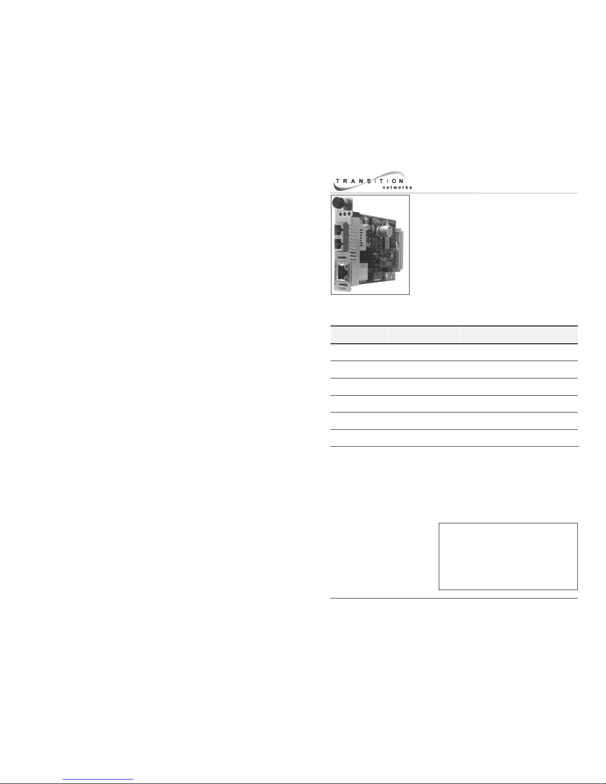
User’s Guide
CGFEB10xx-1xx
Slide-in-Module Media Converter
• Copper to Fiber
• 10/100/1000Base-TX to 1000Base-SX/LX
• Optional Tap Port
Transition Networks CGFEB10xx-1xx series media
converters, designed to be installed in a PointSystem™
chassis connect 10Base-TX, 100Base-TX, or 1000BaseTX twisted-pair copper cable to 1000Base-SX or
1000Base-LX fiber cable.
The CGFEB10xx-10x has one copper port and one fiber-optic port. The distances listed
are the typical maximum cable distance. Actual distance is dependent upon the physical
characteristics of the network installation.
CGFEB10xx-10x
Part Number Port 1 - Copper
10/100/1000-Base-TX
Port 2 - Duplex Fiber-Optic
CGFEB1013-100 RJ-45
100 m (328 ft)
SC, 1000Base-SX, 850 nm multimode
220 m (720 ft)
CGFEB1014-100 RJ-45
100 m (328 ft)
SC, 1000Base-LX, 1310 nm
single mode, 10 km (6.2 miles)
CGFEB1015-100 RJ-45
100 m (328 ft)
SC, 1000Base-LX, 1310 nm
single mode, 25 km (15.5 miles)
CGFEB1017-100 RJ-45
100 m (328 ft)
SC, 1000Base-LX, 1550 nm
single mode, 65 km (40.4 miles)
CGFEB1024-100 RJ-45
100 m (328 ft)
SC, 1000Base-LX, 1300 nm
multimode, 2 km (1.2 miles)*
CGFEB1035-100 RJ-45
100 m (328 ft)
SC, 1000Base-LX, 1550 nm
single mode, 125 km (77.5 miles)
*The CGFEB1024 extends 1000Base-LX beyond 220 meters. Transition Networks
cannot guarantee a full 2-km distance on every installation since the distance is largely
dependent on the quality of the fiber, cable installation and splicing.
Installation . . . . . . . . . . . . . . . . . . . . . . . . 6
Operation . . . . . . . . . . . . . . . . . . . . . . . 13
Diagnostic Monitoring Interface (DMI). . 16
Cable Specification . . . . . . . . . . . . . . . . 17
Technical Specifications . . . . . . . . . . . . 19
Troubleshooting. . . . . . . . . . . . . . . . . . . 20
Contact Us. . . . . . . . . . . . . . . . . . . . . . . 22
Compliance Information . . . . . . . . . . . . 24
Page 2
2
CGFEB10xx-1xx
24-Hour Technical Support: 1-800-260-1312 -- International: 00-1-952-941-7600
CGFEB10xx-1xx -- continued
Part Number Port 1 - Copper
10/100/1000-Base-TX
Port 2 - Single Fiber-Optic
1000Base-SX, single mode
CGFEB1029-100 RJ-45
100 m (328 ft)
SC, 1310 nm TX / 1550 nm RX
20 km (12.4 miles)
CGFEB1029-101 RJ-45,
100 m (328 ft)
SC, 1550 nm TX / 1310 nm RX
20 km (12.4 miles)
CGFEB1029-102 RJ-45
100 m (328 ft)
SC, 1310 nm TX / 1550 nm RX
40 km (24.9 miles)
CGFEB1029-103 RJ-45
100 m (328 ft)
SC, 1550 nm TX / 1310 nm RX
40 km (24.9 miles)
CGFEB1029-104 RJ-45
100 m (328 ft)
SC, 1510nm TX / 1590 nm RX
80 km (49.7 miles)
CGFEB1029-105 RJ-45
100 m (328 ft)
SC, 1590 nm TX / 1510 nm RX
80 km (49.7 miles)
Install CGFEB1029-100 and CGFEB1029-101 in the same network
where one is the local converter and the other is the remote
converter.
Install CGFEB1029-102 and CGFEB1029-103 in the same network
where one is the local converter and the other is the remote
converter.
Install CGFEB1029-104 and CGFEB1029-105 in the same network
where one is the local converter and the other is the remote
converter.
CGFEB10xx-1xx
techsupport@transition.com -- Click the “Transition Now” link for a live Web chat.
3
*Typical maximum cable distance. Actual distance is dependent upon the physical
characteristics of the network.
Note: Third-party Multi-Source Agreement (MSA) compliant Small Form Factor
Pluggables (SFPs) can be used in the CFMFF1040-100.
The following SFP transceiver modules are compatible with the CFMFF1040-1xx
converter and are available from Transition Networks (sold separately).
Part Number Duplex Fiber-Optic Port 2
TN-SFP-SX
LC, 1000Base-SX, 850 nm multimode, 220-550 mm (720-1804 ft)*
TN-SFP-LX1 LC, 1000Base-LX, 1310 nm single mode, 10 km (6.2 miles)*
TN-SFP-LX3 LC, 1000Base-LX, 1310 nm single mode, 30 km (18.8 miles)*
TN-SFP-LX5 LC, 1000Base-LX, 1550 nm single mode, 50 km (31.2 miles)*
TN-SFP-LX8 LC, 1000Base-LX, 1550 nm single mode, 80 km (50.0 miles)*
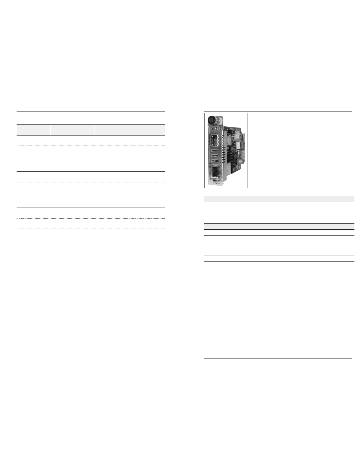
CGFEB1040-1xx
Slide-in-Module Media Converter
• Copper to Fiber
• 10/100/1000Base-TX to 1000Base-SX/LX
• Small Form Fact Pluggable (SFP) Port
Transition Networks CGFEB1040-1xx series media
converters, designed to be installed in a PointSystem™
chassis connect 10Base-TX, 100Base-TX, or 1000Base-TX
twisted-pair copper cable to 1000Base-SX or 1000Base-LX
fiber cable.
The CGFEB1040-10x has one copper port and one SFP port.
The distances listed are the typical maximum cable distance.
Actual distance is dependent upon the physical
characteristics of the network installation.
Copper Port 1: 10/100/1000-Base-TX
RJ-45 100 m (328 ft)
Page 3
4
CGFEB10xx-1xx
24-Hour Technical Support: 1-800-260-1312 -- International: 00-1-952-941-7600
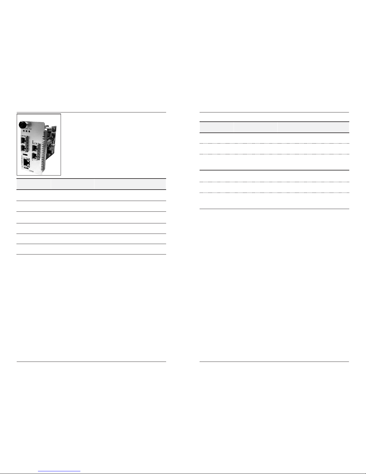
The CGFEB10xx-11x series media converter provides one
copper port (port 1) and one fiber-optic port (port 2). In
addition, the CGFEB10xx-11x provides an additional fiber
tap port (port 3) for a monitoring fiber connection.
Port 3 (1000Base-SX, 850 nm multimode, 220 m) is used for
monitoring the network connection and traffic in any
direction. The fiber tap port “clones” the traffic so the
network analysis does not impact the actual traffic.
The distances listed are the typical maximum cable distance.
Actual distance is dependent upon the physical
characteristics of the network installation.
CGFEB10xx-11x
Part Number Port 1 - Copper
10/100/1000-Base-TX
Port 2 - Duplex Fiber-Optic
CGFEB1013-110 RJ-45
100 m (328 ft)
SC, 1000Base-SX, 850 nm multimode
220 m (720 ft)
CGFEB1014-110 RJ-45
100 m (328 ft)
SC, 1000Base-LX, 1310 nm
single mode, 10 km (6.2 miles)
CGFEB1015-110 RJ-45
100 m (328 ft)
SC, 1000Base-LX, 1310 nm
single mode, 25 km (15.5 miles)
CGFEB1017-110 RJ-45
100 m (328 ft)
SC, 1000Base-LX, 1550 nm
single mode, 65 km (40.4 miles)
CGFEB1024-110 RJ-45
100 m (328 ft)
SC, 1000Base-LX, 1300 nm
multimode, 2 km (1.2 miles)*
CGFEB1035-110 RJ-45
100 m (328 ft)
SC, 1000Base-LX, 1550 nm
single mode, 125 km (77.5 miles)
*The CGFEB1024 extends 1000Base-LX beyond 220 m. Transition Networks cannot
guarantee a full 2 km distance on every installation since the distance is largely
dependent on the quality of the fiber, cable installation and splicing.
CGFEB10xx-1xx
techsupport@transition.com -- Click the “Transition Now” link for a live Web chat.
5
Part Number Port 1 - Copper
10/100/1000-Base-TX
Port 2 - Single Fiber-Optic
1000Base-SX, single mode
CGFEB1029-110 RJ-45
100 m (328 ft)
SC, 1310 nm TX / 1550 nm RX
20 km (12.4 miles)
CGFEB1029-111 RJ-45,
100 m (328 ft)
SC, 1550 nm TX / 1310 nm RX
20 km (12.4 miles)
CGFEB1029-112 RJ-45
100 m (328 ft)
SC, 1310 nm TX / 1550 nm RX
40 km (24.9 miles)
CGFEB1029-113 RJ-45
100 m (328 ft)
SC, 1550 nm TX / 1310 nm RX
40 km (24.9 miles)
CGFEB10xx-11x -- continued
Install CGFEB1029-112 and CGFEB1029-113 in the same
network where one is the local converter and the other is the
remote converter.
Install CGFEB1029-110 and CGFEB1029-111 in the same network
where one is the local converter and the other is the remote
converter.
Page 4
6
CGFEB10xx-1xx
24-Hour Technical Support: 1-800-260-1312 -- International: 00-1-952-941-7600
Installation
CAUTION: Wear a grounding device and observe electrostatic discharge precautions
when setting or installing the media converter. Failure to observe this caution could
result in damage to, and subsequent failure of, the media converter slide-in-module.
Six-position switch
The six-position switch is located on the circuit board of the media converter. Use a
small, flat-blade screwdriver (or a similar device) to set the switch according to the
site the requirements (see the drawing below).
1. Twisted-Pair Auto-Negotiation
UP Enable Auto-Negotiation for the copper connection .
DOWN Disable Auto-Negotiation for the copper connection.
Note: Switches 2 and 3 will not function when twisted-pair Auto-Negotiation is
enabled (switch 1 = UP). The media converter adopts the speed and mode
settings from the device at the other end of the copper link.
2. Twisted-Pair 10Mbs/100Mbs
UP Set copper connection speed to 100Mbs.
DONW Set copper connection speed to 10Mbs.
3. Twisted-Pair Full/Half Duplex
UP Operate in full-duplex mode .
DOWN Operate in half-duplex mode of the attached device.
4. Fiber Auto-Negotiation
UP Enable Auto-Negotiation for the fiber connection .
DOWN Disable Auto-Negotiation for the fiber connection.
5. (not used)
6. Link Pass-Through
UP Enable Link Pass-Through.
DOWN Disable Link Pass-Through.
2. TP 10Mbs/100Mbs
3. TP Half/Full-Duplex
4. Fiber Auto-Negotiation
5. (not used)
1. TP Autonegotiation
6. Link Pass Through
techsupport@transition.com -- Click the “Transition Now” link for a live Web chat.
7
CGFEB10xx-1xx
RX
TX
10/100SX
LKS
PWR
LKM
Singlemode
TX
TX
RX
I
0
TERM
INIT
RX
TX
LNK
PWR
CPSMM120
SERIAL
10BASE-T
R
E
S
E
T
I
0
panel fastener screw
CGFEB10xx-10x CGFEB10xx-11x
Installation -- continued
AutoCross™ jumper
The AutoCross feature allows either straight-through (MDI) or crossover (MDI-X)
cables to be used when connecting to 10Base-T, 100Base-TX, or 1000Base-T
devices, such as hubs, transceivers, or network interface cards (NICs). AutoCross
determines the characteristics of the cable connection and automatically configures
the unit to link up, regardless of the cable configuration.
The AutoCross jumper is located on the media converter’s circuit board (labeled E and
D—see the figures to the right).
Note: Use small needle-nose pliers to set the jumper.
Enabled Either straight-through or crossover cable can be
used for all twisted-pair copper links.
Disabled Straight-through or crossover twisted-pair cable,
depending on installed site devices, MUST be
installed at EACH twisted-pair copper link.
Note: Factory default is “enable.” Transition Networks recommends leaving the
device in the “enable” mode.
Disable Autocross
Enable Autocross
ED
ED
Hardware/software jumper
The hardware/software jumper is located on the circuit board (labeled H and S—
see figure to the right.)
Note: Use small needle-nose pliers to set the jumper.
Hardware The media converter mode is determined by the
6-position switch settings.
Software The media converter mode is determined by the
most-recently saved, on-board microprocessor
settings.
Software Mode
Hardware Mode
HS
HS
Install the slide-in-module
Page 5

8
CGFEB10xx-1xx
24-Hour Technical Support: 1-800-260-1312 -- International: 00-1-952-941-7600
Port Locations
The drawings below illustrate the locations of Port 1, Port 2 and Port 3.
The CGFEB10xx-10x models include Port 1 and Port 2.
The CGFEB10xx-11x models include Port1, Port 2, and Port 3.
CGFEB100
DPX LACT PWR
Port 2
Port 1
CGFEB10xx-10x
Port 3
CGFEB100
DPX LACT PWR
Installation -- continued
Install the slide-in-module -- continued
1a. CGFEB10xx-10x:
Remove one (1) protective plate from one (1) installation slot on the
PointSystem™ chassis by removing the screw that secures the protective plate
to the chassis.
1b. CGFEB10xx-11x:
Remove two (2) protective plates from two (2) adjacent installation slots by
removing the screw that secures each protective plate to the PointSystem™
chassis.
2. Carefully slide the slide-in-module into the installation slot(s), aligning the
module with the installation guides.
3. Ensure that the module is firmly seated inside the chassis.
4. Push in and rotate the attached panel fastener screw clockwise to secure the
module to the chassis.
Port 1: 10/100/1000Base-T
Port 2: 1000Base-SX or 1000Base-LX
Port 3: 1000Base-SX (fiber tap)
techsupport@transition.com -- Click the “Transition Now” link for a live Web chat.
9
CGFEB10xx-1xx
Installation -- continued
Install the cable
Port 1: 10/100/1000Base-TX Copper Port
1. Locate or build 10, 100, or 1000Base-TX compliant copper cables with male,
RJ-45 connectors installed at both ends.
2. Connect the RJ-45 connector at one end of the cable to the media converter’s
10/100/1000Base-TX RJ-45port (port 1).
3. Connect the RJ-45 connector at the other end of the cable to the 10, 100, or
1000Base-TX RJ-45 port on the other device (switch, workstation, etc.).
Note: The AutoCross feature, when enabled, allows the use of either straight-
through or crossover configuration cables.
RJ-45 port
on the other device
(switch, work station, etc.)
RJ-45 port
on the media
converter
Page 6

10
CGFEB10xx-xxx
24-Hour Technical Support: 1-800-260-1312 -- International: 00-1-952-941-7600
Installation -- continued
Port 2: 1000Base-SX/LX Fiber Port
1. Locate or build 1000Base-SX/LX compliant fiber cable with male, twostranded TX to RX connectors installed at both ends.
2. Connect the fiber cables to the media converter’s 1000Base-SX/LX fiber port
(port 2) as described:
• Connect the male TX cable connector to the female TX connector.
• Connect the male RX cable connector to the female RX connector.
3. Connect the fiber cables to the 1000Base-SX/LX fiber port on the other device
(another media converter, hub, etc.) as described:
• Connect the male TX cable connector to the female RX connector.
• Connect the male RX cable connector to the female TX connector.
Connect fiber cable
to media converter
as shown.
Connect fiber cable
to other device
(media converter,
hub, etc.) as shown
RX
TX
RX
TX
techsupport@transition.com -- Click the “Transition Now” link for a live Web chat.
11
Installation -- continued
Port 3: 1000Base-SX tap port (CGFEB10xx-11x models only)
1. Locate or build 1000Base-SX compliant fiber cable with male, two-stranded
TX to RX connectors installed at both ends.
2. Connect the fiber cables to the media converter’s 1000Base-SX tap port
(port 3) as described:
• Connect the male TX cable connector to the female TX connector.
• Connect the male RX cable connector to the female RX connector.
3. Connect the fiber cables to the 1000Base-SX fiber port on the other device
(another media converter, hub, etc.) as described:
• Connect the male TX cable connector to the female RX connector.
• Connect the male RX cable connector to the female TX connector.
Connect fiber cable
to media converter
as shown.
Connect fiber cable
to other device
(media converter,
hub, etc.) as shown
RX
TX
RX
TX
Page 7

techsupport@transition.com -- Click the “Transition Now” link for a live Web chat.
13
Operation
Status LEDs
Use the status LEDs to monitor the media converter operation in the network.
Fiber status LEDs
The status LEDs for the 1000Base-SX/LX fiber
connection (labeled DPX, LACT and PWR) are located
next to the fiber port (Port 2).
PWR Power ON = Connection to external AC power.
LACT Link activity ON = A link has been established for the fiber
connection.
Flashing = The fiber connection is transmitting or
receiving data.
DPX Duplex ON = Full-duplex mode for the fiber connection.
OFF = Half-duplex mode for the fiber connection.
Copper status LEDs
The status LEDs for the copper connection are integrated
into the RJ-45 port. These LEDs are not labeled on the
media converter. Refer to the drawing to the right for
their locations.
Duplex/Link:
Yellow A link in half-duplex mode has been established for
the copper connection.
Flashing Yellow The copper connection is transmitting/receiving data
in half-duplex mode.
Green A link in full-duplex mode has been established for
the copper connection.
Flashing Green The copper connection is transmitting/receiving data
in full-duplex mode.
Speed:
OFF 10 Mb/s operation.
Yellow 100 Mb/s operation.
Green 1000 Mb/s operation.
PWRLACTDPX
Duplex/Link Speed
10/100TX
12
CGFEB10xx-xxx
24-Hour Technical Support: 1-800-260-1312 -- International: 00-1-952-941-7600
Powering the slide-in-module
The slide-in-module is powered through the Transition Networks PointSystem™
chassis.
1000Base-TX switch000Base-TX switch
CGFEB10xx-11xCGFEB10xx-10x
220 m
to 65 km
LAN Analyzer monitors
the network traffic
via the tap port
Installation -- continued
CGFEB10xx-11x in the network
The diagram below illustrates how the fiber tap port of the CGFEB10xx-11x is used
to link to a LAN analyzer in order to monitor the fiber traffic.
Page 8

14
CGFEB10xx-xxx
24-Hour Technical Support: 1-800-260-1312 -- International: 00-1-952-941-7600
Operation -- continued
Product features
Auto-Negotiation
The Auto-Negotiation feature allows the CGFEB10xx-1xx media converter to
automatically configure itself to achieve the best possible mode of operation over a
link. The media converter broadcasts its speed (10 Mb/s, 100 Mb/s, or 1000 Mb/s)
and duplex capabilities (full or half) to the other devices and negotiates the best
mode of operation. Auto-Negotiation allows quick and easy installation because the
optimal link is established automatically. No user intervention is required to
determine the best mode of operation.
A scenario where the media converter is linked to a non-negotiating device is a case
where the user may want to disable Auto-Negotiation. In this instance, the mode of
operation will drop to the least common denominator between the two devices (e.g.
100 Mb/s, half-duplex). Disabling this feature gives the user the ability to force the
connection to the best mode of operation.
Note: The CGFEB10xx-1xx and SGFEB10xx-1xx also support 1000 Mb/s fiber
Auto-Negotiation.
Link Pass-Through
The Link Pass-Through feature allows the media converter to monitor both the fiber
and copper RX (receive) ports for loss of signal. In the event of a loss of an RX
signal (1), the media converter will automatically disable the TX (transmit) signal
(2), thus, “passing through” the link loss (3). The far-end device is automatically
notified of the link loss (4), which prevents the loss of valuable data unknowingly
transmitted over an invalid link.
Full-Duplex Network
In a full-duplex network, maximum cable lengths are determined by the type of
cables that are used. See cable specifications for the different CGFEB10xx-1xx
models.
The 512-Bit Rule does not apply in a full-duplex network.
1
Media
Converter A
Media
Converter B
Near-End
Device
Far-End
Device
original fault on
the copper link
Media converter B
disables the copper lin
k
Media converter A disables
the Fiber TX link
Media converter B disables
the Fiber RX link
3
2
4
x
techsupport@transition.com -- Click the “Transition Now” link for a live Web chat.
15
Operation -- continued
Product features—continued
Half-Duplex network (512-Bit Rule)
In a half-duplex network, the maximum cable lengths are determined by the round
trip delay limitations of each Fast Ethernet collision domain. (A collision domain is
the longest path between any two terminal devices, e.g. a terminal, switch, or
router.)
The 512-Bit Rule determines the maximum length of cable permitted by calculating
the round-trip delay in bit-times (BT) of a particular collision domain. If the result
is less than or equal to 512 BT, the path is good.
For more information on the 512-Bit Rule, see the white paper titled “Collision
Domains” on the Transition Networks website at: www.transition.com.
Pause
The pause feature is used to temporarily suspend data transmission in order to
relieve buffer congestion. If a media converter needs some time to clear network
congestion, it will send a pause signal to the media converter at the other end, which
will wait a predetermined amount of time before re-transmitting the data. This
feature reduces data bottlenecks, allows for a more efficient use of the network
devices, and prevents the loss of valuable data.
In Hardware mode, the pause feature can be set to the following:
• Disable (i.e., no pause)
• Enable (i.e., symmetrical pause)
In Software mode, the pause feature can be set to one of four settings:
• Disable (i.e., no pause)
• Symmetrical pause
• Asymmetric TX (transmit) pause
• Asymmetric RX (receive) pause
Note: Enable the pause feature if it is present on ALL network devices attached to
the media converter(s). Otherwise, disable the pause feature.
SNMP
See the on-line documentation that comes with Transition Networks FocalPoint™
software for applicable commands and usage.
Use SNMP at an attached terminal or at a remote location to monitor the media
converter by monitoring:
• Copper and fiber link status
• Copper and fiber port duplex
• Copper port speed
lso, use SNMP to enter network commands that:
• Set copper full/half-duplex
• Set copper connection speed (10Mbs / 100Mbs / 1000Mbs)
• Enable/Disable Link Pass-Through
• Enable/Disable Auto-Negotiation
• Select transmit (TX) or receive (RX) on the optional tap port
Page 9

16
CGFEB10xx-xxx
24-Hour Technical Support: 1-800-260-1312 -- International: 00-1-952-941-7600
Diagnostic Monitoring Interface (DMI)
The following DMI port screen and explanation table contains brief definitions of the
DMI support offered on Transition Networks SFP optical interfaces. For further
information, please see the help option on the CPSMM-xxx SNMP agent or Focal
Point, Transition Networks' GUI.
Variable Name Description
DMI Rx Power Measured Receive optical power in microwatts and in decibels
relative to 1mW.
DMI Rx Power Alarm Alarm status of measured Receive optical power.
DMI Temp Internally measured temperature of transceiver in degrees C and
degrees F.
DMI Temp Alarm Alarm status for internally measured temperature of transceiver.
DMI Bias Current Measured transmit bias current in microamperes.
DMI Bias Alarm Alarm status for measured transmit bias current for the
interface.
DMI Tx Power Measured transmit power, in microwatts and in decibels relative
to 1mW..
DMI Tx Power Alarm Alarm status of measured transmit power.
Rx Power Intrusion
Threshold
Instructs the converter to stop passing traffic when the receive
power drops below the new threshold. This feature is
sometimes referred to as 'Intrusion Detection,' since tapping
into a fiber to intercept traffic leads to a reduction in receive
power. This value can be entered in microwatts or in decibels
relative to 1mW.
Note: This feature is not available on all devices.
techsupport@transition.com -- Click the “Transition Now” link for a live Web chat.
17
CGFEB10xx-1xx
Cable Specifications
The physical characteristics must meet or exceed IEEE 802.3™ specifications.
Fiber cable
Bit Error Rate: <10-9
Single mode fiber (recommended): 9 µm
Multimode fiber (recommended): 62.5/125 µm
Multimode fiber (optional): 100/140, 85/140, 50/125 µm
CGFEB1013-100, CGFEB1013-110 850 nm multimode
Fiber Optic Transmitter Power: min: -10.0 dBm max: -4.0 dBm
Fiber Optic Receiver Sensitivity: min: -17.0 dBm max: 0.0 dBm
Link Budget: 7.5 dB
CGFEB1014-100, CGFEB1014-110 1310 nm single mode
Fiber Optic Transmitter Power: min: -13.0 dBm max: -3.0 dBm
Fiber Optic Receiver Sensitivity: min: -20.0 dBm max: -3.0 dBm
Link Budget: 7.0 dB
CGFEB1015-100, CGFEB1015-110 1310 nm single mode
Fiber Optic Transmitter Power: min: -5.0 dBm max: -0.0 dBm
Fiber Optic Receiver Sensitivity: min: -20.0 dBm max: -3.0 dBm
Link Budget: 15.0 dB
CGFEB1017-100, CGFEB1017-110 1550 nm single mode
Fiber Optic Transmitter Power: min: -3.0 dBm max: 2.0 dBm
Fiber Optic Receiver Sensitivity: min: -23.0 dBm max: -3.0 dBm
Link Budget: 20.0 dB
CGFEB1029-100, CGFEB1029-110 1310 TX/1550 RX nm single mode
Fiber Optic Transmitter Power: min: -8.0 dBm max: -3.0 dBm
Fiber Optic Receiver Sensitivity: min: -21.0 dBm max: -3.0 dBm
Link Budget: 13.0 dB
CGFEB1029-101, CGFEB1029-111 1550 TX/1310 RX nm single mode
Fiber Optic Transmitter Power: min: -8.0 dBm max: -3.0 dBm
Fiber Optic Receiver Sensitivity: min: -21.0 dBm max: -3.0 dBm
Link Budget: 13.0 dB
CGFEB1029-102, CGFEB1029-112 1310 TX/1550 RX nm single mode
Fiber Optic Transmitter Power: min: -3.0 dBm max: +2.0 dBm
Fiber Optic Receiver Sensitivity: min: -23.0 dBm max: -8.0 dBm
Link Budget: 20.0 dB
CGFEB1029-103, CGFEB1029-113 1550 TX/1310 RX nm single mode
Fiber Optic Transmitter Power: min: -3.0 dBm max: +2.0 dBm
Fiber Optic Receiver Sensitivity: min: -23.0 dBm max: -8.0 dBm
Link Budget: 20.0 dB
Page 10

18
CGFEB10xx-1xx
24-Hour Technical Support: 1-800-260-1312 -- International: 00-1-952-941-7600
Cable Specification -- continued
Fiber cable -- continued
CGFEB1029-104, 1510 TX/1590 RX nm single mode
Fiber Optic Transmitter Power: min: -2.0 dBm max: +3.0 dBm
Fiber Optic Receiver Sensitivity: min: -26.0 dBm max: -3.0 dBm
Link Budget: 24.0 dB
CGFEB1029-105 1590 TX/1510 RX nm single mode
Fiber Optic Transmitter Power: min: -2.0 dBm max: +3.0 dBm
Fiber Optic Receiver Sensitivity: min: -26.0 dBm max: -3.0 dBm
Link Budget: 24.0 dB
CGFEB1035-100, CGFEB1035-110 1550 nm single mode
Fiber-optic Transmitter Power: min: 0.0 dBm max: +5.0 dBm
Fiber-optic Receiver Sensitivity: min: -32.0 dBm max: -8.0 dBm
Link Budget: 32.0 dB
CGFEB1024-100, CGFEB1024-110 1300 nm multimode **
Fiber Optic Transmitter Power: min: -10.0 dBm max: -4.0 dBm
Fiber Optic Receiver Sensitivity: min: -17.0 dBm max: -3.0 dBm
Link Budget: 7.0 dB
**Fiber cable for CGFEB1024-100 and CGFEB1024-110 must be 62.5/125
µm.
The fiber optic transmitters on this device meet Class I Laser safety
requirements per IEC-825/CDRH standards and comply with 21 CFR1040.10
and 21CFR1040.11.
Copper cable
Category 5 (minimum requirement)
Gauge: 24 to 22 AWG
Attenuation: 22.0 dB /100 m @ 100 MHz
Maximum Cable Distance: 100 meters
• Straight-through OR crossover twisted-pair cable may be used.
• Shielded (STP) OR unshielded (UTP) twisted-pair cable may be used.
• All pin pairs (1&2, 3&6, 4&5, 7&8) are active pins in a Gigabit Ethernet network.
• Use only dedicated wire pairs for the active pins:
(e.g., blue/white & white/blue, orange/white & white/orange, etc.)
• Do not use flat or silver satin wire.
techsupport@transition.com -- Click the “Transition Now” link for a live Web chat.
19
CGFEB10xx-1xx
Technical Specifications
For use with Transition Networks Model CGFEB10xx-1xx.
Standards: IEEE 802.3™, IEEE 802.1p™
CGFEB10xx-10x:
Case Dimensions: 5.0" x 3.4" x 0.87" (182 x 86 x 22 mm)
Weight: 4.5 oz (128 g)
Power Consumption: 7.28 watts
CGFEB10xx-11x:
Case Dimensions: 5.0" x 3.4" x 1.75" (182 x 86 x 43 mm)
Weight: 7.5 oz (213 g)
Power Consumption: 7.84 watts
Data Rate (copper): 10, 100, 1000 Mb/s
Data Rate (fiber): 1000 Mb/s (operates in full-duplex only)
Latency: 64 256 1024 1518 (frame size)
1000Base-T: 3.2 4.8 10.9 14.8 micro seconds
1000Base-SX/LX: 3.2 4.8 10.9 14.8 micro seconds
Packet Size: Unicast MAC address: 4K bytes
Maximum packet size: 1536 bytes
Memory: 256K bytes (2 Mbit
)
MTBF: 474,000 hours (MIL217F2V5.0) (MIL-HDBK-217F)
1,317,000 hours (Bellcore7 V5.0)
Environment: Tmra*: 0°C to 50°C (32°F to 122°F)
Storage Temp: -40°C to 85°C (-40°F to 185°F)
Humidity: 5% to 95%, non-condensing
Altitude: 0 to 10,000 feet
Warranty: Lifetime
* Manufacturer’s rated ambient temperature: Tmra range for the CGFEB10xx-20x
depends on the Transition Networks PointSystem™ chassis in which this slide-inmodule will be installed.
The information in this user’s guide is subject to change. For the most up-to-date
information, see the user’s guide on-line at: www.transition.com.
Product is certified by the manufacturer to comply with DHHS Rule 21/CFR, Subchapter
J applicable at the date of manufacture.
CAUTION:
Visible and invisible laser radiation when open. Do not stare into the beam
or view directly with optical instruments.
CAUTION: Use of controls, adjustments or the performance of procedures other than
those specified herein may result in hazardous radiation exposure.
Page 11

20
CGFEB10xx-1xx
24-Hour Technical Support: 1-800-260-1312 -- International: 00-1-952-941-7600
Troubleshooting
1. Is the Power LED illuminated?
NO
• Is the media converter inserted properly into the chassis?
• Is the power cord properly installed in the chassis and in the grounded AC
outlet?
• Does the grounded AC outlet provide power?
• Contact Tech Support: 1-800-260-1312, Int’l: 00-1-952-941-7600.
YES
• Proceed to step 2.
2. Is the Duplex LED illuminated yellow OR green?
NO
• Check the copper cables for proper connection.
• Contact Tech Support: 1-800-260-1312, Int’l: 00-1-952-941-7600.
YES - Yellow
• The media converter has selected half-duplex mode. If this is not the
correct mode, disconnect and reconnect the copper cable to restart the
initialization process.
• Proceed to step 3.
YES - Green
• The media converter has selected full-duplex mode. If this is not the
correct mode, disconnect and reconnect the copper cable to restart the
initialization process.
• Proceed to step 3.
3. Is the LACT LED illuminated?
NO
• Check the fiber cables for proper connection.
• Verify that the TX and RX cables on the media converter are connected to
the RX and TX ports, respectively, on the other device.
• Contact Tech Support: 1-800-260-1312, Int’l: 00-1-952-941-7600.
YES
• Proceed to step 4.
4. Is the DPX LED illuminated?
YES
• The converter has selected full-duplex mode for the fiber link. If this is
not the correct mode, disconnect and reconnect the fiber cable to restart
the initialization process.
• Proceed to step 5.
NO
• The converter has selected half-duplex mode for the fiber link. If this is
not the correct mode, disconnect and reconnect the fiber cable to restart
the initialization process.
• Proceed to step 5.
21
techsupport@transition.com -- Click the “Transition Now” link for a live Web chat.
CGFEB10xx-1xx
Troubleshooting -- continued
5. Is the Speed LED illuminated?
NO
• The media converter has selected 10 Mb/s operation. If this is not the
correct speed, disconnect and reconnect the copper cable to restart the
initialization process.
• Contact Tech Support: 1-800-260-1312, Int’l: 00-1-952-941-7600.
YES - Flashing Yellow
• The media converter has selected 100 Mb/s speed. If this is not the
correct speed, disconnect and reconnect the copper cable to restart the
initialization process.
• Contact Tech Support: 1-800-260-1312, Int’l: 00-1-952-941-7600.
YES - Flashing Green
• The media converter has selected 1000 Mb/s operation. If this is not the
correct speed, disconnect and reconnect the copper cable to restart the
initialization process.
• Contact Tech Support: 1-800-260-1312, Int’l: 00-1-952-941-7600.
Page 12

22
CGFEB10xx-1xx
24-Hour Technical Support: 1-800-260-1312 -- International: 00-1-952-941-7600
Contact Us
Technical Support
Technical support is available 24 hours a day.
US and Canada: 1-800-260-1312
International: 00-1-952-941-7600
Transition Now
Chat live via the Web with Transition Networks Technical Support.
Log onto www.transition.com and click the Transition Now link.
Web-Based Seminars
Transition Networks provides seminars via live web-based training.
Log onto www.transition.com and click the Learning Center link.
E-Mail
Ask a question anytime by sending an e-mail to our technical support staff.
techsupport@transition.com
Address
Transition Networks
6475 City West Parkway
Minneapolis, MN 55344, U.S.A.
telephone: 952-941-7600
toll free: 800-526-9267
fax: 952-941-2322
CGFEB10xx-1xx
techsupport@transition.com -- Click the “Transition Now” link for a live Web chat.
23
Declaration of Conformity
Name of Mfg: Transition Networks
6475 City West Parkway, Minneapolis MN 55344 U.S.A.
Model: CGFEB10xx-1xx Series Media Converters
Part Number(s): CGFEB1013-100, CGFEB1014-100, CGFEB1015-100, CGFEB1017-100,
CGFEB1024-100, CGFEB1029-100, CGFEB1035-100, CGFEB1040-100
CGFEB1029-101, CGFEB1029-102, CGFEB1029-103, CGFEB1029-104,
CGFEB1029-105, CGFEB1013-110, CGFEB1014-110, CGFEB1015-110,
CGFEB1017-110, CGFEB1024-110, CGFEB1029-110, CGFEB1029-111,
CGFEB1029-112, CGFEB1029-113, CGFEB1035-110
Regulation: EMC Directive 89/336/EEC
Purpose: To declare that the CGFEB10xx-1xx to which this declaration refers is in conformity
with the following standards.
CISPR 22: 1993; EN 55022:1994 A1:1995 A2:1997 Class A; EN 55024:1998; FCC Part 15 Subpart B;
21 CFR subpart J
I, the undersigned, hereby declare that the equipment specified above conforms to the above Directive(s) and
Standard(s).
January 3, 2006
Stephen Anderson, Vice-President of Engineering Date
Page 13

Trademark Notice
All trademarks and registered trademarks are the property of their respective owners.
Copyright Restrictions
© 2003-2005 Transition Networks.
All rights reserved. No part of this work may be reproduced or used in any form or by any means graphic, electronic, or mechanical - without written permission from Transition Networks.
CGFEB10xx-1xx
24
Printed in the U.S.A. 33276.H
Compliance Information
CISPR22/EN55022 Class A + EN55024
CE Mark
FCC Regulations
This equipment has been tested and found to comply with the limits for a Class A digital device,
pursuant to part 15 of the FCC rules. These limits are designed to provide reasonable protection
against harmful interference when the equipment is operated in a commercial environment. This
equipment generates, uses, and can radiate radio frequency energy and, if not installed and used in
accordance with the instruction manual, may cause harmful interference to radio communications.
Operation of this equipment in a residential area is likely to cause harmful interference, in which
case the user will be required to correct the interference at the user's own expense.
Canadian Regulations
This digital apparatus does not exceed the Class A limits for radio noise for digital apparatus
set out on the radio interference regulations of the Canadian Department of Communications.
Le présent appareil numérique n'émet pas de bruits radioélectriques dépassant les limites applicables
aux appareils numériques de la lass A prescrites dans le Règlement sur le brouillage radioélectrique
édicté par le ministère des Communications du Canada.
European Regulations
Warning
This is a Class A product. In a domestic environment this product may cause radio interference in
which case the user may be required to take adequate measures.
Achtung !
Dieses ist ein Gerät der Funkstörgrenzwertklasse A. In Wohnbereichen können bei Betrieb dieses
Gerätes Rundfunkstörungen auftreten. In diesem Fäll ist der Benutzer für Gegenmaßnahmen
verantwortlich.
Attention !
Ceci est un produit de Classe A. Dans un environment domestique, ce produit risque de créer des
interférences radioélectriques, il appartiendra alors à l'utilsateur de prende les measures spécifiques
appropriées.
In accordance with European Union Directive 2002/96/EC of the European Parliament
and of the Council of 27 January 2003, Transition Networks will accept post usage
returns of this product for proper disposal. The contact information for this activity can
be found in the 'Contact Us' portion of this document.
CAUTION: RJ connectors are NOT INTENDED FOR CONNECTION TO THE
PUBLIC TELEPHONE NETWORK. Failure to observe this caution could result in
damage to the public telephone network.
Der Anschluss dieses Gerätes an ein öffentlickes Telekommunikationsnetz in den EGMitgliedstaaten verstösst gegen die jeweligen einzelstaatlichen Gesetze zur Anwendung der
Richtlinie 91/263/EWG zur Angleichung der Rechtsvorschriften der Mitgliedstaaten über
Telekommunikationsendeinrichtungen einschliesslich der gegenseitigen Anerkennung ihrer
Konformität.
 Loading...