

Page 1
Installation
Instructions
Disassembly and Reassembly Units
Series S™ Water-Cooled CenTraVac™ Chillers
Model: CVHS
SAFETY WARNING
Only qualified personnel should install and service the equipment. The installation, starting up, and servicing
of heating, ventilating, and air-conditioning equipment can be hazardous and requires specific knowledge and
training. Improperly installed, adjusted or altered equipment by an unqualified person could result in death or
serious injury. When working on the equipment, observe all precautions in the literature and on the tags,
stickers, and labels that are attached to the equipment.
February 2019
CVHS-SVN04E-EN
X39641248060
Page 2
Introduction
Read this manual thoroughly before operating or servicing
this unit.
Warnings, Cautions, and Notices
Safety advisories appear throughout this manual as
required. Your personal safety and the proper operation of
this machine depend upon the strict observance of these
precautions.
The three types of advisories are defined as follows:
WARNING
CAUTIONs
NOTICE
Important Environmental Concerns
Scientific research has shown that certain man-made
chemicals can affect the earth’s naturally occurring
stratospheric ozone layer when released to the
atmosphere. In particular, several of the identified
chemicals that may affect the ozone layer are refrigerants
that contain Chlorine, Fluorine and Carbon (CFCs) and
those containing Hydrogen, Chlorine, Fluorine and
Carbon (HCFCs). Not all refrigerants containing these
compounds have the same potential impact to the
environment. Trane advocates the responsible handli ng of
all refrigerants-including industry replacements for CFCs
and HCFCs such as saturated or unsaturated HFCs and
HCFCs.
Important Responsible Refrigerant
Practices
Trane believes that responsible refrigerant practices are
important to the environment, our customers, and the air
conditioning industry. All technicians who handle
refrigerants must be certified according to local rules. For
the USA, the Federal Clean Air Act (Section 608) sets forth
the requirements for handling, reclaiming, recovering and
recycling of certain refrigerants and the equipment that is
used in these service procedures. In addition, some states
or municipalities may have additional requirements that
must also be adhered to for responsible management of
refrigerants. Know the applicable laws and follow them.
Indicates a potentially hazardous
situation which, if not avoided, could
result in death or serious injury.
Indicates a potentially hazardous
situation which, if not avoided, could
result in minor or moderate injury. It
could also be used to alert against
unsafe practices.
Indicates a situation that could result in
equipment or property-damage only
accidents.
WARNING
Proper Field Wiring and Grounding
Required!
Failure to follow code could result in death or serious
injury. All field wiring MUST be performed by qualified
personnel. Improperly installed and grounded field
wiring poses FIRE and ELECTROCUTION hazards. To
avoid these hazards, you MUST follow requirements for
field wiring installation and grounding as described in
NEC and your local/state electrical codes.
WARNING
Personal Protective Equipment (PPE)
Required!
Failure to wear proper PPE for the job being undertaken
could result in death or serious injury. Technicians, in
order to protect themselves from potential electrical,
mechanical, and chemical hazards, MUST follow
precautions in this manual and on the tags, stickers,
and labels, as well as the instructions below:
• Before installing/servicing this unit, technicians
MUST put on all PPE required for the work being
undertaken (Examples; cut resistant gloves/sleeves,
butyl gloves, safety glasses, hard hat/bump cap, fall
protection, electrical PPE and arc flash clothing).
ALWAYS refer to appropriate Material Safety Data
Sheets (MSDS)/Safety Data Sheets (SDS) and OSHA
guidelines for proper PPE.
• When working with or around hazardous chemicals,
ALWAYS refer to the appropriate MSDS/SDS and
OSHA/GHS (Global Harmonized System of
Classification and Labelling of Chemicals) guidelines
for information on allowable personal exposure
levels, proper respiratory protection and handling
instructions.
• If there is a risk of energized electrical contact, arc, or
flash, technicians MUST put on all PPE in accordance
with OSHA, NFPA 70E, or other country-specific
requirements for arc flash protection, PRIOR to
servicing the unit. NEVER PERFORM ANY
SWITCHING, DISCONNECTING, OR VOLTAGE
TESTING WITHOUT PROPER ELECTRICAL PPE AND
ARC FLASH CLOTHING. ENSURE ELECTRICAL
METERS AND EQUIPMENT ARE PROPERLY RATED
FOR INTENDED VOLTAGE.
© 2019 Ingersoll Rand CVHS-SVN04E-EN
Page 3
WARNING
Follow EHS Policies!
Failure to follow instructions below could result in
death or serious injury.
• All Ingersoll Rand personnel must follow Ingersoll
Rand Environmental, Health and Safety (EHS)
policies when performing work such as hot work,
electrical, fall protection, lockout/tagout, refrigerant
handling, etc. All policies can be found on the BOS
site. Where local regulations are more stringent than
these policies, those regulations supersede these
policies.
• Non-Ingersoll Rand personnel should always follow
local regulations.
Introduction
location specified by the contractor. The contractor shall
provide the rigging equipment such as chain falls,
gantries, cranes, forklifts, etc. necessary for the
disassembly and reassembly work and the required
qualified personnel to operate the necessary rigging
equipment.
Copyright
This document and the information in it are the property of
Trane, and may not be used or reproduced in whole or in
part without written permission. Trane reserves the right
to revise this publication at any time, and to make changes
to its content without obligation to notify any person of
such revision or change.
Trademarks
Factory Warranty Information
Compliance with the following is required to preserve the
factory warranty:
All Unit Installations
Startup MUST be performed by Trane, or an authorized
agent of Trane, to VALIDATE this WARRANTY. Contractor
must provide a two-week startup notification to Trane (or
an agent of Trane specifically authorized to perform
startup).
Additional Requirements for Units Requiring
Disassembly and Reassembly
When a new chiller is shipped and received from our Trane
manufacturing location and, for any reason, it requires
disassembly or partial disassembly, and reassembly—
which could include but is not limited to the evaporator,
condenser, control panel, compressor/motor, economizer,
purge, factory-mounted starter or any other components
originally attached to the fully assembled unit—
compliance with the following is required to preserve the
factory warranty:
• Trane, or an agent of Trane specifically authorized to
perform start-up and warranty of Trane
perform or have direct on-site technical supervision of
the disassembly and reassembly work.
• The installing contractor must notify Trane—or an
agent of Trane specifically authorized to perform
startup and warranty of Trane
in advance of the scheduled disassembly work to
coordinate the disassembly and reassembly work.
• Start-up must be performed by Trane or an agent of
Trane specifically authorized to perform startup and
warranty of Trane
Trane, or an agent of Trane specifically authorized to
perform start-up and warranty of Trane
provide qualified personnel and standard hand tools to
perform the disassembly and reassembly work at a
®
products.
®
products—two weeks
®
products, will
®
products, will
All trademarks referenced in this document are the
trademarks of their respective owners.
Revision History
Updated AFD information.
CVHS-SVN04E-EN 3
Page 4

Table of Contents
Components and Weights . . . . . . . . . . . . . . . . 5
Components . . . . . . . . . . . . . . . . . . . . . . . . . . 5
Maximum Component Weights . . . . . . . . . 8
Disassembly . . . . . . . . . . . . . . . . . . . . . . . . . . . . 9
General Information . . . . . . . . . . . . . . . . . . . 9
Contractor Responsibilities . . . . . . . . . . . . . 9
Wiring Disassembly . . . . . . . . . . . . . . . . . . . . 9
Unit-mounted Starter Removal . . . . . . . . . 10
Purge Unit Removal . . . . . . . . . . . . . . . . . . 11
Control Panel Removal . . . . . . . . . . . . . . . . 12
Tracer AdaptiView Display Arm Removal 13
Compressor Motor Assembly Removal . . 13
Economizer Removal . . . . . . . . . . . . . . . . . . 16
Condenser/Evaporator Disassembly . . . . . 17
Optional Hinged Waterboxes . . . . . . . . . 18
Reassembly . . . . . . . . . . . . . . . . . . . . . . . . . . . . 20
Optional Hinged Waterboxes . . . . . . . . . 21
Tightening Flanges . . . . . . . . . . . . . . . . . . 21
Flanges with 8 or 12 Screws . . . . . . . . . . 21
Flanges with 16 Screws . . . . . . . . . . . . . . 22
Brazing . . . . . . . . . . . . . . . . . . . . . . . . . . . . . . 22
Final Installation Procedures . . . . . . . . . . . 23
4 CVHS-SVN04D-EN
Page 5
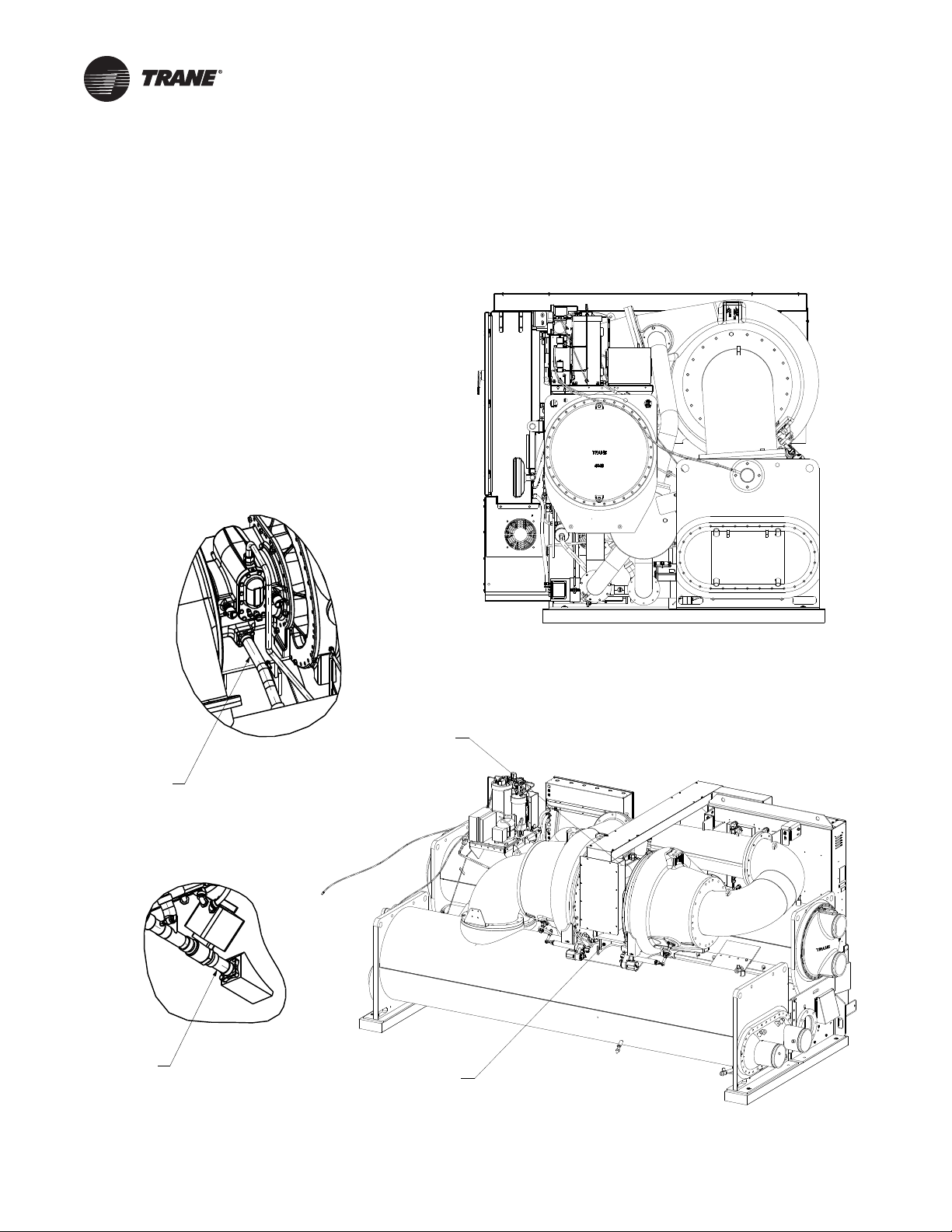
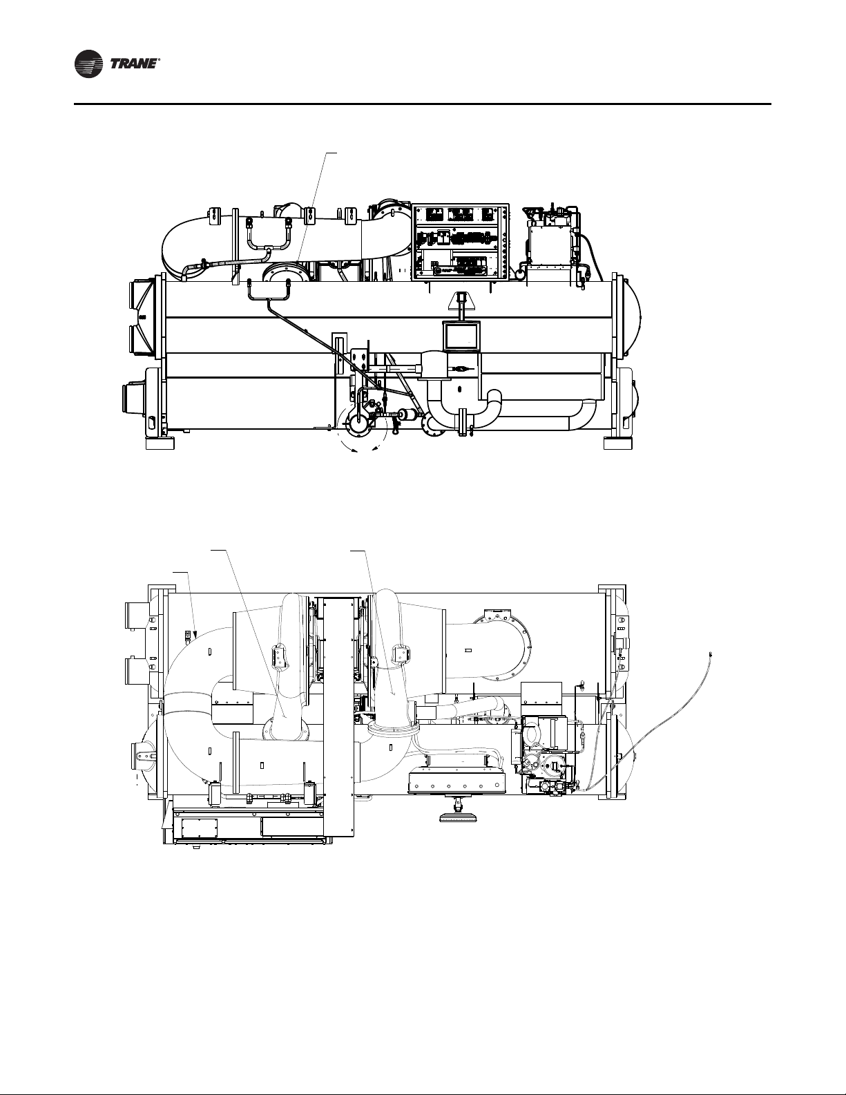
Components and Weights
Condenser
Evaporator
Economizer
Motor Casting
Compressor Base
Motor Cooling
Return Tube
Detail A
Refrigerant
Pump Suction
Connection
Detail B
Important: All fasteners are metric except waterbox
hardware.
Note: Use only new O-rings and gaskets. Do NOT reuse
O-rings or gaskets.
Figure 1. CVHS Components (page 1 of 2)
Components
CVHS-SVN04E-EN 5
Page 6
Components and Weights
Condenser Discharge Connection
B
2
nd
Volute Di scharge
1
st
Volute Di scharge
Wrap Around Pipe
Figure 1. CVHS Components (page 2 of 2)
6 CVHS-SVN04E-EN
Page 7
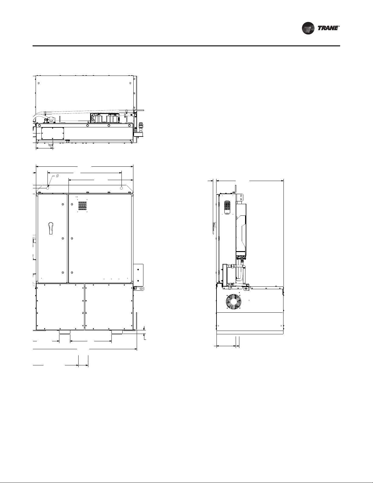
Figure 2. CVHS drive dimensions, in.
56-5/8
15-11/16 5-5/8 22
1-7/8
CENTER
OF GRAVITY
26 TO 31
CENTER
OF GRAVITY
10 TO 12
51-5/16
6-1/8 39
1-3/8
1-3/4 35-7/16
34-1/16
8-13/16
Components and Weights
Note: The holes on the top of the drive can be used for
lifting the drive.
CVHS-SVN04E-EN 7
Page 8
Components and Weights
Maximum Component Weights
Table 1. Maximum CVHS unit component weights
Maximum Weight
Component
Condenser without waterboxes 4253 1934
Condenser waterboxes
Evaporator without waterboxes 6095 2771
Evaporator waterboxes(a) 776 353
Economizer 348 159
Compressor 5474 2483
Compressor wrap pipe 770 350
Compressor suction elbow 361 164
Control panel 88 40
Purge 165 75
Drive 1900 862
Wire tray with lid 57 26
Shipping (Estimated) 22611 10193
Shipping without drive (Estimated) 20787 9429
Operating (Estimated) 25837 11656
(a)Optional waterbox hinges: each wat erbox h inge wei ghs 35 l b (15.9 kg);
optional waterbox hinges are not included in the estimated maximum
weights.
(a)
(lb) (kg)
923 420
Important: Two M20 swivel D-rings are required for
lifting the compressor assembly (metric
threads).
Note: Wrap pipe requires three 5/8-in. shackles. Trane
recommends using Crosby screw pin shackles,
model S-209, stock number 1018482 with 5/8-in.
pin.
8 CVHS-SVN04E-EN
Page 9

Disassembly
General Information
WARNING
Refrigerant under Positive Pressure!
Failure to follow instructions below could result in an
explosion which could result in death or serious injury
or equipment damage. System contains refrigerant and
may be under positive pressure. Recover refrigerant to
relieve pressure before opening the system. See unit
nameplate for refrigerant type. Do not use nonapproved refrigerants, refrigerant substitutes, or
refrigerant additives.
Important: Remove the nitrogen charge from the chiller
vessel before starting any disassembly
procedures.
Note: New units ship with a 5 psig (34.5 kPag) dry
nitrogen holding charge at nominal 72°F (22.2°C).
Important: New units that have been factory run-tested
contain residual refrigerant; vent discharge
outdoors.
• Check to make sure there is a positive pressure holding
charge.
Contractor Responsibilities
WARNING
Heavy Objects!
Failure to follow instructions below or properly lift
component could result in component dropping and
possibly crushing operator/technician which could
result in death or serious injury, and equipment or
property-only damage. Ensure that all the lifting
equipment used is properly rated for the weight of the
component being lifted. Each of the cables (chains or
slings), hooks, and shackles used to lift the component
must be capable of supporting the entire weight of the
component. Lifting cables (chains or slings) may not be
of the same length. Adjust as necessary for even
component lift.
• Protect all internal components from exposure to
elements, which could contaminate or corrode chiller
components
• Chiller reassembly
• Replace all gaskets with new gaskets or O-rings and
sealing compound; the contractor should assist a
qualified Trane Technician with this responsibility
• Evacuate the chiller under 1000 microns; the contractor
should assist a qualified Trane Technician with this
responsibility
• Recharge the chiller with dry nitrogen to 5 psig; the
contractor should assist a qualified Trane Technician
with this responsibility
• Replace and/or repair insulation
• Reconnect electrical connections
• Spot paint the chiller if necessary
The disassembly and reassembly procedures described in
this manual should be performed only on chillers that have
been ordered with this shell option. The process is to be
initiated by experienced service technicians. Contact your
local Trane Service office for assistance if required.
This manual discusses a typical disassembly process.
Proper lifting techniques vary based on mechanical room
layout.
• It is the responsibility of the person(s) performing the
work to be properly trained in the safe practice of
rigging, lifting, securing, and fastening the
components involved.
• It is the responsibility of the person(s) providing and
using the rigging and lifting devices to inspect these
devices to ensure they are free from defect and are
rated to meet or exceed the published weights.
• Always use rigging and lifting devices in accordance
with the applicable instructions for such devices.
• Cap or cover open lines to prevent entry of foreign
material
Note: Additional O-rings and couplings are shipped with
Also refer to wiring diagram 2311-3555*.
.
the chiller when the separable shell kit is selected.
Wiring Disassembly
NOTICE
Equipment Damage!
Failure to remove the strain relief with the sensor could
result in equipment damage. Do NOT attempt to pull
sensor bulb through the strain relief; always remove
the entire strain relief with the sensor.
• Handle/lift and rig equipment
CVHS-SVN04E-EN 9
Before separating shells, remove the purge, the
compressor, wrap pipe, economizer line, control panel,
and the various unit mounted sensors (frame LLIDs) as
indicated. If possible, the best method is to remove the
sensor and carefully coil the wire after labeling the device
and its location to aid in reinstallation. All sensors connect
to the buss wiring with a universal plug. This allows easy
disconnection and reconnection of the sensors.
Page 10

Disassembly
Unit-mounted Starter Removal
If you need to temporarily remove the entire AFD cabinet
from the chiller to allow unit installation through restricted
spaces or the AFD cabinet shipped disassembled from the
chiller, use the following general information and
instructions. The maximum weight of the drive is 1900 lb
(862 kg).
Note: For specific weights of the AFD cabinet, refer to
submittal package.
WARNING
Heavy Objects!
Failure to follow instructions below or properly lift
component could result in component dropping and
possibly crushing operator/technician which could
result in death or serious injury, and equipment or
property-only damage. Ensure that all the lifting
equipment used is properly rated for the weight of the
component being lifted. Each of the cables (chains or
slings), hooks, and shackles used to lift the component
must be capable of supporting the entire weight of the
component. Lifting cables (chains or slings) may not be
of the same length. Adjust as necessary for even
component lift.
WARNING
Improper Unit Lift!
Failure to properly lift unit could result in death or
serious injury or possible equipment or property-only
damage. Test lift unit approximately 24 inches (61 cm)
to verify proper center of gravity lift point. To avoid
dropping of unit, reposition lifting point if unit is not
level.
1. Remove the AFD upper support bracket hex head
screws at the wrap-around pipe side. There are two
screws in each bracket.
2. Close the isolation valves for the AFD cooling lines,
both feed and return.
WARNING
Hazard of Explosion and Deadly Gases!
Failure to follow all proper safe refrigerant handling
practices could result in death or serious injury.
Never solder, braze or weld on refrigerant lines or any
unit components that are above atmospheric pressure
or where refrigerant may be present. Always remove
refrigerant by following the guidelines established by
the EPA Federal Clean Air Act or other state or local
codes as appropriate. After refrigerant removal, use dry
nitrogen to bring system back to atmospheric pressure
before opening system for repairs. Mixtures of
refrigerants and air under pressure may become
combustible in the presence of an ignition source
leading to an explosion. Excessive heat from soldering,
brazing or welding with refrigerant vapors present can
form highly toxic gases and extremely corrosive acids.
WARNING
Refrigerant under Positive Pressure!
Failure to follow instructions below could result in an
explosion which could result in death or serious injury
or equipment damage. System contains refrigerant and
may be under positive pressure. Recover refrigerant to
relieve pressure before opening the system. See unit
nameplate for refrigerant type. Do not use nonapproved refrigerants, refrigerant substitutes, or
refrigerant additives.
Important: Any unit pressure must be relieved before
disconnecting refrigerant lines. The units
ship from the factory with a 5 psi dry
nitrogen holding charge.
3. Disconnect the AFD cooling lines at the bottom of the
elbows coming out of the chill plate, both feed and
return. Cap the lines and chill plate elbows to prevent
debris from entering the system.
4. Mark and disconnect the motor power wires at the
drive output terminals and inside motor junction box.
There will be six power wires and two ground wires.
Note: Always compare the wire connections to the
as-built wiring diagrams to assure the
schematics match the actual connections. Make
notes as necessary to assure the wires are
reconnected to the same locations.
5. Remove wire tray covers and completely remove wires
from wire tray. Disassemble and remove the wire tray
by unscrewing the tray at the compressor junction box
and then removing the screws from support bracket on
the AFD cabinet.
6. Mark and disconnect the high pressure cutout switch
wires at the terminal block and pull the cable out of the
AFD cabinet.
10 CVHS-SVN04E-EN
Page 11

7. Mark and disconnect the wires that run between the
drive and the control panel at the drive and pull the
conduit out of the AFD cabinet.
8. Mark and disconnect the refrigerant pump wires from
the terminal block and pull conduit out of the AFD
cabinet.
9. Mark and disconnect drive communication cable at
terminal block and pull the cable out of the AFD
cabinet.
10. Support the weight of the AFD cabinet with a fork truck
or another suitable lifting device (minimum 2-ton rated
capacity).
11. Loosen and remove the hex head screws that secure
the AFD cabinet to the lower mounting brackets.
Unhook the right side at the L-bracket welded to the
condenser, four screws total. Unhook the left side at
the condenser support leg, four screws and nuts total.
12. Carefully lift the AFD cabinet away from the chiller. Do
NOT bump or jolt the AFD while lifting.
Installation of the AFD cabinet is essentially the reverse of
the removal procedure. All mounting screws should be
torqued to ANSI standards based on the screw diameter.
The motor power wires connecting to the drive output
terminals should be torqued according to the label inside
the AFD cabinet. Tighten the control wires that connect to
the AFD terminal block to 8.3 ft-lb (11.3 N-m). The motor
powers wires connecting to the motor terminals inside the
compressor motor junction box shall be torqued between
20–26 ft·lb. Torque the corresponding ground cables
inside the compressor motor junction box to 38 ft·lb. Refer
to the as-built wiring diagrams for connection locations.
Purge Unit Removal
Disassembly
WARNING
Hazardous Voltage w/Capacitors!
Disconnect all electric power, including remote
disconnects and discharge all motor start/run
capacitors before servicing. Follow proper lockout/
tagout procedures to ensure the power cannot be
inadvertently energized. Verify with an appropriate
voltmeter that all capacitors have discharged. Failure to
disconnect power and discharge capacitors before
servicing could result in death or serious injury.
For additional information regarding the safe discharge
of capacitors, see PROD-SVB06A-EN
To remove the purge assembly from the top of the
condenser:
1. Isolate the purge unit from the condenser shell by
closing the vapor and liquid line valves.
2. Disconnect and mark all piping and wiring attached to
the purge unit. Sand all paint off at points and use a
tubing cutter where cuts are to be made. See Figure 3,
p. 11 and Figure 4, p. 12.
3. Remove the fasteners connecting the purge unit base
to its mounting bracket.
4. Two people will be needed to lift purge unit clear of the
chiller. Refer to Table 1, p. 8 for purge unit weight.
Store the purge unit in a clean dry area.
Reassemble the purge unit in reverse order when the
process is complete.
Figure 3. Purge unit
WARNING
Refrigerant under Positive Pressure!
Failure to follow instructions below could result in an
explosion which could result in death or serious injury
or equipment damage. System contains refrigerant and
may be under positive pressure. Recover refrigerant to
relieve pressure before opening the system. See unit
nameplate for refrigerant type. Do not use nonapproved refrigerants, refrigerant substitutes, or
refrigerant additives.
CVHS-SVN04E-EN 11
Page 12

Disassembly
Cut for coupling
Figure 4. Purge unit detail
3. Loosen the two hex head screws on the back of the
panel which secure the panel to the top mounting
brackets. See Figure 5.
Figure 5. Control panel mounting brackets
Control Panel Removal
WARNING
Hazardous Voltage w/Capacitors!
Failure to disconnect power and discharge capacitors
before servicing could result in death or serious injury.
Disconnect all electric power, including remote
disconnects and discharge all motor start/run
capacitors before servicing. Follow proper lockout/
tagout procedures to ensure the power cannot be
inadvertently energized. For variable frequency drives
or other energy storing components provided by Trane
or others, refer to the appropriate manufacturer’s
literature for allowable waiting periods for discharge of
capacitors. Verify with an appropriate voltmeter that all
capacitors have discharged.
For additional information regarding the safe discharge
of capacitors, see PROD-SVB06A-EN
Use the following steps to remove the control panel if
additional vertical clearance is required.
Note: The control panel can be rotated back and
downward on two mounting screws with wiring
remaining intact.
1. Mark and disconnect incoming wiring to the control
panel.
2. Remove the four hex head screws from the bottom of
the panel which secure the panel to the lower
mounting brackets.
Figure 6. Control panel mounting brackets details
4. Two people will be needed to lift the panel clear of the
chiller. Refer to Table 1, p. 8 for control panel weight.
Steady the panel as the top retaining screws are
removed. Then lift the panel clear. Store the panel in a
clean dry area.
12 CVHS-SVN04E-EN
Page 13

Disassembly
5. Use the reverse order to reassemble the control panel.
Tracer AdaptiView Display Arm Removal
WARNING
Hazardous Voltage w/Capacitors!
Failure to disconnect power and discharge capacitors
before servicing could result in death or serious injury.
Disconnect all electric power, including remote
disconnects and discharge all motor start/run
capacitors before servicing. Follow proper lockout/
tagout procedures to ensure the power cannot be
inadvertently energized. For variable frequency drives
or other energy storing components provided by Trane
or others, refer to the appropriate manufacturer’s
literature for allowable waiting periods for discharge of
capacitors. Verify with an appropriate voltmeter that all
capacitors have discharged.
For additional information regarding the safe discharge
of capacitors, see PROD-SVB06A-EN
Use the following steps to remove the Tracer
AdaptiView™ display arm if additional clearance is
required.
1. Cut tie wraps holding wires inside of control arm and
remove wires from arm.
2. Remove four hex head screws from the display arm
base connecting to the condenser bracket.
3. Use the reverse order to re-attach the arm to the
control panel mounting bracket.
Compressor Motor Assembly Removal
Figure 7. Compressor dowelings to baseplate
a. Remove the cotter pins and washers securing the
vane operator studs to the vane drive and slide the
vane actuators off the mounting studs.
b. Mark each actuator “right” or “left,” accordingly,
and replace in the correct location.
Figure 8. Vane actuator and operator details
WARNING
Refrigerant under Positive Pressure!
Failure to follow instructions below could result in an
explosion which could result in death or serious injury
or equipment damage. System contains refrigerant and
may be under positive pressure. Recover refrigerant to
relieve pressure before opening the system. See unit
nameplate for refrigerant type. Do not use nonapproved refrigerants, refrigerant substitutes, or
refrigerant additives.
2. Disconnect motor cooling supply and drain line that is
connected to the compressor motor. Couplings will be
used to reconnect the lines when reassembling the
chiller. Cap or cover open lines to prevent entry of
foreign material
.
1. Disconnect the vane actuators.
CVHS-SVN04E-EN 13
Page 14

Disassembly
Cut for
coupling
Figure 9. Lubrication system
Figure 10. Lubrication system detail
equipped. See “Control Panel Removal,” p. 12 for
instructions.
4. Remove the economizer vent pipe flange hex head
screws at the compressor and economizer connection.
See “Economizer Removal,” p. 16 for instructions.
WARNING
Heavy Objects!
Failure to follow instructions below or properly lift
component could result in component dropping and
possibly crushing operator/technician which could
result in death or serious injury, and equipment or
property-only damage. Ensure that all the lifting
equipment used is properly rated for the weight of the
component being lifted. Each of the cables (chains or
slings), hooks, and shackles used to lift the component
must be capable of supporting the entire weight of the
component. Lifting cables (chains or slings) may not be
of the same length. Adjust as necessary for even
component lift.
5. Before removing the compressor/motor assembly,
consult with a rigging specialist. Employ rigging
specialist procedures when removing the compressor
motor/assembly.
Important: Two M20 swivel D-rings are required for
lifting the compressor assembly (metric
threads).
WARNING
Improper Use of Elbow Lifting Tab!
Using the elbow lifting tab to lift chiller could result in
chiller dropping which could result in death, serious
injury, or equipment damage. Do NOT lift chiller using
elbow lifting tab. Elbow lifting tab and approved clevis
are used ONLY when removing elbow from chiller.
6. Remove the suction elbow.
a. The suction elbow has lifting tabs. You will need a
lifting clevis to remove the elbow. A Crosby screw
pin shackle, model S-209, stock number 1018482
with a 5/8-in. pin is acceptable as shown in
Figure 11.
3. Remove the control panel if necessary. Also,
disconnect and remove the unit mounted starter, if so
14 CVHS-SVN04E-EN
Page 15

Figure 11. Lifting clevis on the suction elbow lifting tab
Lift points for
M20 swivel D-rings
Disassembly
c. Remove the second stage volute-to-condenser hex
head screws.
8. Use designated lift point for level lift.
a. If the wrap pipe is still on the unit, see Figure 12.
b. If lifting the compressor only (no wrap pipe), see
Figure 13.
Figure 12. Wrap pipe lifting points (requires three
5/8-in. shackles to lift)
b. Remove the suction elbow hex head screws at the
compressor and evaporator connections.
c. Lift the suction elbow from the chiller being careful
to avoid damage to flange surfaces.
Note: Compressor assembly can be removed
with wrap pipe still installed.
d. Unscrew the economizer vent pipe at the first stage
volute connection and at the economizer
connection.
e. The two-piece wrap pipe has four lifting tabs. You
will need three lifting clevises to remove the pipe. A
Crosby screw pin shackle, model S-209, stock
number 1018482 with a 5/8-in. pin is acceptable as
shown in Figure 11.
f. Remove the first stage discharge volute hex head
screws and the second stage suction hex head
screws.
7. If required by installation dimension constraints,
remove the two-piece wrap pipe. The wrap pipe can be
disassembled at the mid-flange joint.
a. Lift the wrap pipe from the chiller, being careful to
avoid damaging flange surfaces.
b. Install protective covers on the evaporator, wrap
pipe, and compressor connections. Plastic secured
with duct tape makes an adequate cover if no heavy
objects are set on the openings.
Figure 13. Compressor-only lifting points
CVHS-SVN04E-EN 15
Page 16

Disassembly
Figure 14. Casting identifies lifting points by
component
9. Support compressor on wood blocks or plywood to
prevent damage to the compressor or wrap pipe
components.
NOTICE
Handle with Care!
Failure to follow instructions below could result in
equipment damage.
The cast iron base of the compressor and the discharge
flange of the volute can be broken easily if rough
handling of the compressor/motor assembly is allowed.
Take great care to prevent this breakage when removing
the compressor/motor assembly and setting it down, or
when moving it laterally on the floor (e.g., on rollers, etc).
Take extra care to gently sit the compressor/motor
assembly down and avoid letting it swing or drop into an
obstruction while lifting or moving it.
10. Remove the compressor/motor assembly. Remove the
two locating roll pins from the compressor and/or
compressor base. Grip each pin and pull out of its hole;
at this point, remove the compressor/motor assembly.
Economizer Removal
WARNING
Heavy Objects!
Failure to follow instructions below or properly lift
component could result in component dropping and
possibly crushing operator/technician which could
result in death or serious injury, and equipment or
property-only damage. Ensure that all the lifting
equipment used is properly rated for the weight of the
component being lifted. Each of the cables (chains or
slings), hooks, and shackles used to lift the component
must be capable of supporting the entire weight of the
component. Lifting cables (chains or slings) may not be
of the same length. Adjust as necessary for even
component lift.
WARNING
Refrigerant under Positive Pressure!
Failure to follow instructions below could result in an
explosion which could result in death or serious injury
or equipment damage. System contains refrigerant and
may be under positive pressure. Recover refrigerant to
relieve pressure before opening the system. See unit
nameplate for refrigerant type. Do not use nonapproved refrigerants, refrigerant substitutes, or
refrigerant additives.
Use the following steps to remove the economizer if
additional horizontal clearance is required.
1. Support the weight of the economizer with a movable
floor jack. Do NOT lift the economizer; simply support
it. Maximum economizer weight is provided inTable 1,
p. 8; also see submittal.
2. If the unit has insulation, remove the insulation and
loosen the hex head screws on the condenser liquid
line flange. Loosen the hex head screws on the
evaporator liquid line flange. See Figure 15. Do NOT
remove the screws at this time.
16 CVHS-SVN04E-EN
Page 17

Figure 15. Evaporator-Condenser-Economizer line
flanges
3. This connection is near the bottom of the evaporator.
See Figure 15. Do NOT remove the screws at this time.
4. Economizers are connected to the evaporator shell via
screwed flanges. See Figure 17, p. 18. Remove the
screws at this flanged connection.
5. Remove the economizer vent pipe flange hex head
screws on the economizer and the vent pipe to the
compressor first stage volute connection flange hex
head screws. Remove economizer vent line (unless the
compressor has already been removed to gain vertical
clearance.)
6. Secure economizer with appropriate rigging.
7. Remove the hex head screws from the condenser and
evaporator liquid line connection flanges. Adjust the
floor jack as necessary to support the weight of the
economizer.
8. Remove the economizer vent pipe flange screws to
loosen the economizer. When the screws are free, back
the economizer away from the chiller. The economizer
may tend to rotate off the jack. Be prepared to offset
any rotation.
9. Move the economizer away from the chiller and set it
on a pallet. Cover all openings to prevent the entry of
foreign material into the economizer, condenser and
compressor.
Disassembly
10. Use the reverse order to reassemble the economizer
on the chiller. Be sure to install new O-rings at the
appropriate joints.
11. Torque all screws to specifications. Consult with your
Trane service group for specific torques for your
economizer design.
Condenser/Evaporator Disassembly
After the compressor assembly has been removed, the
condenser and evaporator shells can be taken apart at
flanged connections to reduce the horizontal clearance
required for the chiller installation.
WARNING
Heavy Objects!
Failure to follow instructions below or properly lift
component could result in component dropping and
possibly crushing operator/technician which could
result in death or serious injury, and equipment or
property-only damage. Ensure that all the lifting
equipment used is properly rated for the weight of the
component being lifted. Each of the cables (chains or
slings), hooks, and shackles used to lift the component
must be capable of supporting the entire weight of the
component. Lifting cables (chains or slings) may not be
of the same length. Adjust as necessary for even
component lift.
1. Ensure that condenser and evaporator shells are
securely supported on level ground. If not, shim under
the bases.
2. Support the condenser with rigging using the lifting
holes on the tube sheets. See Figure 16. Do NOT lift the
shell, simply support it to avoid slipping as the screws
are removed from the connecting flange.
Figure 16. Separable shell unit
CVHS-SVN04E-EN 17
Page 18

Disassembly
3. Remove the hex head screws from the flanges
connecting the evaporator tube sheet and condenser
shell support (see Figure 17). Then remove the screws
from the flanges connecting the shells.
4. Reassemble the evaporator and condenser shells in
the reverse order.
Note: Install the top screws first as these have limited
clearance and act as dowel pins.
5. Torque all screws to specifications listed in Table 2,
p. 21.
Figure 17. Separable shell unit (flange connection)
Optional Hinged Waterboxes
If the chiller includes optional hinged waterboxes, the
waterboxes and hinge may be removed for installation or
service.
Figure 18. Example of CVHS hinged waterbox option
(non-marine waterbox)
18 CVHS-SVN04E-EN
Page 19

Figure 19. Example of CVHS hinged waterbox option
(marine waterbox)
Disassembly
Each waterbox hinge weighs 35 lb (15.9 kg); refer to
Table 1, p. 8 for condenser and evaporator waterbox
maximum weights.
CVHS-SVN04E-EN 19
Page 20

Reassembly
NOTICE
Equipment Damage!
Failure to remove the strain relief with the sensor could
result in equipment damage. Do NOT attempt to pull
sensor bulb through the strain relief; always remove
the entire strain relief with the sensor.
It is important to remove used O-rings and gaskets and
clean joints before reassembling the compressor with new
O-rings. All necessary replacement O-rings are supplied
by the factory when the separable shell option is ordered.
Use the following procedure to reattach the
compressor/motor assembly to the chiller.
1. Remove the protective covers on all compressor,
condenser, evaporator, and economizer connections.
Clean all mating surfaces using Loctite
cleaner or CRC
Completely remove old sealing compound from O-ring
grooves. Use Loctite “N” primer for final surface
preparation.
2. Refer to CTV-SB-66F (General Service Bulletin:
CenTraVac O-Ring and Flange Sealant) for proper
installation of gaskets, O-Rings, and Loctite sealant.
Install a new O-ring on the compressor discharge
connection mating surfaces. Use Loctite 515 “Gasket
Eliminator” to lubricate the O-ring and provide
additional sealing. This is the only sealing compound
recommended by Trane for use on O-ring joints. To use
this sealing compound, apply a light bead
(approximately 1/8-in. in diameter) to the O-ring
groove, insert the O-ring and then apply a light bead to
the O-ring. Also apply a 1/8-in. bead of sealing
compound between the O-ring groove and the screw
hole circle. The parts can now be assembled.
Note: Trim 3/8-in. off the 2-1/8-in. copper compressor
drain line to allow clearance when
reassembling.
3. Lift the compressor/motor assembly into place. Be
sure to caulk or paint the compressor base plate to
protect the bare metal. Install two new roll pins into the
compressor casting. Align the pins into the
compressor mounting base. Insert the hex head
screws in the compressor base and discharge flange
connections.
4. Tighten the compressor base and discharge flange hex
head screws. See Table 2, p. 21 for screw torque
specifications.
5. Remove the lifting equipment.
6. Set up dial indicators on the compressor end of the
compressor/motor assembly. See Figure 20. The dial
indicators are used to monitor horizontal and vertical
movement of the compressor/motor assembly when
the suction elbow retaining hex head screws are
®
Industrial Gasket Remover.
®
“Chisel”
tightened. Support the dial indicators from the
condenser or from a floor stand.
Figure 20. Suction elbow flange screws
(a) For flange tightening sequences, refer to “Tightening Flanges,” p. 21
7. Clean the suction elbow flange surfaces and O-ring
grooves per Step 1. For the evaporator to suction
elbow joint, use Loctite 515 per Step 2. For the suction
elbow to compressor joint, use 1/8-in. GORE-TEX
Joint Sealant placed approximately 1/8-in. in board of
the O-ring groove. This is used in addition to the
O-ring. Also use 1/8-in. GORE-TEX on wrap pipe to
second stage inlet connection in the same manner as
on the section elbow to compressor joint.
As an option, Loctite 515 may be used in place of
GORE-TEX. However, great care must be taken to
prevent the sealant from entering the first stage IGV
housing. Refer to CTV-SB-66F (General Service
Bulletin: CenTraVac O-Ring and Flange Sealant).
(a)
®
20 CVHS-SVN04E-EN
Page 21

Reassembly
Figure 21. Installation of 1/8-in. GORE-TEX tape
8. Lift the suction elbow into place using a sling or chainfall hoist.
9. Install the suction elbow retaining hex head screws.
10. Tighten the retaining screws only “hand tight”. Tighten
two retaining screws, 180 degrees apart at the
compressor connection. Then tighten two screws,
180 degrees apart at the evaporator connection.
Alternate between connections until all retaining
screws are tight. Monitor the dial indicators to ensure
that there is no more than 0.010 inches of compressor
movement. If there is more movement than this,
loosen all of the screws, “zero” the dial indicators, and
repeat the procedure. Refer to “Tightening Flanges,”
p. 21 for screw tightening sequences.
11. Reconnect the economizer vent pipe. Be sure to clean
the mating surfaces and use new O-rings on the
connections. Tighten first stage volute and economizer
top flange screws; refer to Table 2, p. 21 and
“Tightening Flanges,” p. 21.
12. Reinstall all other chiller components which were
removed.
13. Torque all screws to specifications listed in Table 2.
Table 2. Screw torques for waterbox mounting
Screw Size Torque
(in) (mm) (ft·lb) (N·m)
1/2 13 70–100 95–136
5/8 16 130–190 176–258
Metric Screw Size (Non-Gasketed Joints or O-ring Joints)
Torque
Screw Size
M8 12–16 16–22
M10 24–33 33–45
M12 48–65 65–89
M16 130–179 177–243
M20 239–334 324–453
(ft·lb) (N·m)
14. Reconnect the previously cut compressor supply and
return lines and the motor cooling lines using the
factory-supplied couplings.
Optional Hinged Waterboxes
If the chiller includes optional hinged waterboxes and if the
waterboxes have been removed for installation or service,
or if waterbox holes do not line up with the tube sheet,
perform the following procedure.
1. Move waterbox into position.
2. Install the hex head screws for the waterbox and handtighten.
3. Lift and hold the waterbox as high as the screws will
allow.
4. While holding the waterbox as high as the screws will
allow, tighten the waterbox screws to the tube sheet.
Torque to specifications listed in Table 2.
5. Move hinge into position.
6. Install hinge button head screws and hand-tighten.
7. Torque button head screws for center hinge section to
waterbox to specifications listed in Table 2.
8. Lift lower hinge section and hold in contact with middle
hinge section.
9. Torque button head screws for lower hinge section to
tube sheet to specifications listed in Table 2.
10. Torque button head screws for upper hinge section to
tube sheet to specifications listed in Table 2.
Each waterbox hinge weighs 35 lb (15.9 kg); refer to
Table 1, p. 8 for condenser and evaporator waterbox
maximum weights.
Tightening Flanges
Flanges with 8 or 12 Screws
Tighten all screws to a snug tightness, following the
numerical sequence for the appropriate pattern as shown
below. Repeat this sequence to apply the final torque to
each screw.
CVHS-SVN04E-EN 21
Page 22

Reassembly
1
3
45
7
8
26
8 screws
1
3
4
10 11
9
5
7
8
12
26
12 screws
1
5
9
2
3
4
6
7
8
10
16
15
14
13
12
11
16 screws
Flanges with 16 Screws
Tighten only the first half of the total number of screws to
a snug tightness, following the numerical sequence for the
pattern as shown below. Next, sequentially tighten the
remaining half of the screws in numerical order.
Brazing
WARNING
Hazard of Explosion and Deadly Gases!
Failure to follow all proper safe refrigerant handling
practices could result in death or serious injury.
Never solder, braze or weld on refrigerant lines or any
unit components that are above atmospheric pressure
or where refrigerant may be present. Always remove
refrigerant by following the guidelines established by
the EPA Federal Clean Air Act or other state or local
codes as appropriate. After refrigerant removal, use dry
nitrogen to bring system back to atmospheric pressure
before opening system for repairs. Mixtures of
refrigerants and air under pressure may become
combustible in the presence of an ignition source
leading to an explosion. Excessive heat from soldering,
brazing or welding with refrigerant vapors present can
form highly toxic gases and extremely corrosive acids.
Except as noted in the following, braze with the following
filler metals:
• Braze all copper-to-copper joints with A.W.S. BcuP-6
filler metal.
• Braze all copper-to-brass joints with A.W.S.
filler metal using white or black brazing flux.
• Braze all other joints with A.W.S. Bag-28 filler metal.
Bleed dry nitrogen through the lines while brazing to
prevent the formation of oxides which can contaminate
the refrigerant systems.
Note: Use silver soldering with 96% Sn-4% Ag (for
example, J.W. Harris Co. Stay Brite
brazing when the heat from brazing would be
detrimental to the immediate or nearby parts.
Examples:
1. Joints next to threaded joints in which the copper or
brass threads become too soft and/or Loctite loses its
sealing capability due to excess heat.
2. Joints next to valves in which the valves cannot be
taken apart or are not recommended for brazing.
BcuP-6
®
) to replace
22 CVHS-SVN04E-EN
Page 23

Final Installation Procedures
After the chiller has been moved to the equipment room
and reassembled under Trane supervision, leak testing,
and evacuation can be performed by Trane or under Trane
supervision. Upon verification of leak tightness,
installation can proceed for unit piping, wiring, etc. After
installation has been completed, fill out CTV-ADF001*-EN
(CenTraVac™ Installation Completion Check Sheet and
Request for Trane Service) to schedule the startup; the
chiller commissioning process can be completed by Trane
or under the supervision of authorized Trane personnel.
Note: CTV-ADF001*-EN is also included in the “Forms”
section of CVHS-SVX01*-EN (Installation,
Operation, and Maintenance: Series S™ WaterCooled CenTraVac Chillers with Tracer AdaptiView
Control).
Reassembly
CVHS-SVN04E-EN 23
Page 24

Ingersoll Rand (NYSE:IR) advances the quality of life by creating comfortable, sustainable and efficient
ingersollrand.com
environments. Our people and our family of brands—including Club Car®, Ingersoll Rand®, Thermo King® and
Trane®—work together to enhance the quality and comfort of air in homes and buildings; transport and protect
food and perishables; and increase industrial productivity and efficiency. We are a global business committed to a
world of sustainable progress and enduring results.
Ingersoll Rand has a policy of continuous product and product data improvement and reserves the right to change design and specifications
without notice.
We are committed to using environmentally conscious print practices.
CVHS-SVN04E-EN 22 Feb 2019
Supersedes CVHS-SVN04D-EN (Jul 2017)
©2019 Ingersoll Rand
 Loading...