

Page 1
Installation, Operation,
and Maintenance
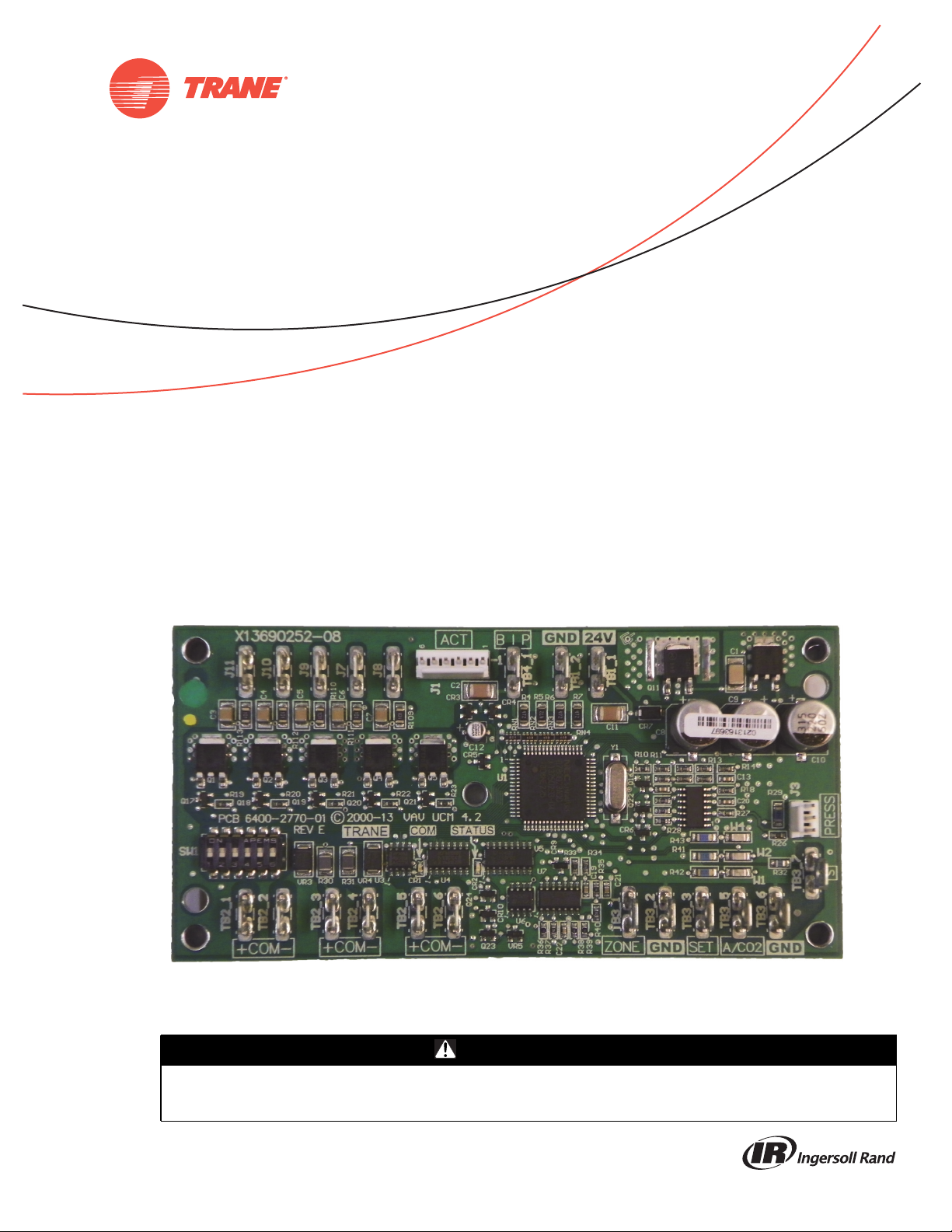
VAV-UCM 4.2
SAFETY WARNING
Only qualified personnel should install and service the equipment. The installation, starting up, and servicing of heating, ventilating, and airconditioning equipment can be hazardous and requires specific knowledge and training. Improperly installed, adjusted or altered equipment
by an unqualified person could result in death or serious injury.When working on the equipment, observe all precautions in the literature and
on the tags, stickers, and labels that are attached to the equipment.
March 2014
VAV-SVX01D-EN
Page 2
Introduction
Read this manual thoroughlybefore operatingor servicing
this unit.
Warnings, Cautions, and Notices
Safety advisories appear throughout this manual as
required.Your personal safety and the proper operation of
this machine depend upon the strict observance of these
precautions.
The three types of advisories are defined as follows:
WARNING
Proper FieldWiring and Grounding
Required!
Failure to follow code could result in death or serious
injury. All field wiring MUST be performed by qualified
personnel. Improperly installed and grounded field
wiring poses FIRE and ELECTROCUTION hazards. To
avoid these hazards, you MUST follow requirements for
field wiring installation and grounding as described in
NEC and your local/state electrical codes.
WARNING
CAUTIONs
NOTICE:
Indicates a potentially hazardous
situation which, if not avoided, could
result in death or serious injury.
Indicates a potentially hazardous
situation which, if not avoided, could
result in minor or moderate injury. It
could also be used to alert against
unsafe practices.
Indicates a situationthat could resultin
equipment or property-damage only
accidents.
Important Environmental Concerns
Scientific research has shown that certain man-made
chemicals can affect the earth’s naturally occurring
stratospheric ozone layer when released to the
atmosphere. In particular, several of the identified
chemicals that may affect the ozone layer are refrigerants
that contain Chlorine, Fluorine and Carbon (CFCs) and
those containing Hydrogen, Chlorine, Fluorine and
Carbon (HCFCs). Not all refrigerants containing these
compounds have the same potential impact to the
environment.Trane advocates the responsible handlingof
all refrigerants-including industry replacements for CFCs
such as HCFCs and HFCs.
Important Responsible Refrig er ant Practices
Trane believes that responsible refrigerant practices are
important to the environment, our customers, and the air
conditioning industry. All technicians who handle
refrigerants must be certified.The Federal Clean Air Act
(Section 608) sets forth the requirements for handling,
reclaiming, recovering and recycling of certain
refrigerants and the equipment that is used in these
service procedures. In addition, some states or
municipalities may have additional requirements that
must also be adhered to for responsible management of
refrigerants. Know the applicable laws and follow them.
WARNING
Personal Protective Equipment (PPE)
Required!
Installing/servicing this unit could result in exposure to
electrical, mechanical and chemical hazards.
• Before installing/servicing this unit, technicians
MUST put on all PPE required for the work being
undertaken (Examples; cut resistant gloves/sleeves,
butyl gloves, safety glasses, hard hat/bump cap, fall
protection, electrical PPE and arc flash clothing).
ALWAYS refer to appropriate Material Safety Data
Sheets (MSDS)/Safety Data Sheets (SDS) and OSHA
guidelines for proper PPE.
• When working with or around hazardous chemicals,
ALWAYS refer to the appropriate MSDS/SDS and
OSHA/GHS (Global Harmonized System of
Classification and Labelling of Chemicals) guidelines
for information on allowable personal exposure
levels, proper respiratory protection and handling
instructions.
• If there is a risk of energized electrical contact, arc, or
flash, technicians MUST put on all PPE in accordance
with OSHA, NFPA 70E, or other country-specific
requirements for arc flash protection, PRIOR to
servicing the unit. NEVER PERFORM ANY
SWITCHING, DISCONNECTING, OR VOLTAGE
TESTING WITHOUT PROPER ELECTRICAL PPE AND
ARC FLASH CLOTHING. ENSURE ELECTRICAL
METERS AND EQUIPMENT ARE PROPERLY RATED
FOR INTENDED VOLTAGE.
Failure to follow instructions could result in death or
serious injury.
© 2014 Trane All rights reserved VAV-SVX01D-EN
Page 3

Copyright
This document andthe information in it arethe property of
Trane, and may not be used or reproduced in whole or in
part without written permission.Trane reserves the right
to revise this publication at any time, and to make changes
to its content without obligation to notify any person of
such revision or change.
Trademarks
VariTrac,VariTrane, Trane and theTrane logo are
trademarks or registered trademarks ofTrane in the United
States and other countries.Trane is a business of Ingersoll
Rand. All trademarks referenced in this document are the
trademarks of their respective owners.
Revision History
VAV-SVX01D-EN
Updated board photo and part number (BRD04939
replaced BRD02806).
Introduction
VAV-SVX01D-EN 3
Page 4

Table of Contents
Introduction ............................. 2
Warnings, Cautions, and Notices ........ 2
Important Environmental Concerns ..... 2
Important Responsible Refrigerant
Practices ........................... 2
General Information ..................... 6
Overview of Manual ................... 6
Chapter Overview ..................... 6
Unit Control Module 4.2 (UCM 4.2) ....... 6
Specifications ....................... 6
UCM 4.2 Enhancements ............... 6
UCM 4.2 Features .................... 7
Shipping ........................... 8
Storage ............................ 8
VAV Start Up/Check Out Procedure ........ 9
Chapter Overview ..................... 9
UCM 4.2 Pre-Power Check-Out .......... 9
Light Emitting Diode (LED) Operations ... 9
Zone Sensor Check-out ................ 10
UCM 4.2 Installation and Wiring ......... 11
Chapter Overview .................... 11
UCM 4.2 Power Wiring ................ 11
Power Requirements ................ 11
Zone Sensor Wiring ................... 11
Location and Mounting .............. 11
Wiring ............................ 11
Multiple UCM’s Per Zone Sensor ...... 12
Multiple UCM’s per Auxiliary Duct
Temperature Sensor ................ 12
Zone Sensor Hardwired Option ....... 12
Zone Sensor Wireless Option ......... 12
Communication Wiring ................ 12
Communication Link Wiring .......... 12
DIP Switch Settings ................... 13
Wireless Zone Sensor ................... 17
Overview ............................ 17
Dimensional Diagrams ................ 17
Setting the Address, Mounting, Wiring,
and Associating the Receiver and Sensor
18
Choosing a Location for Mounting
the Sensor ..........................18
Setting the Rotary Address Switches
on the Receiver and the Sensor ........19
Factory Wiring of the Receiver to
theVAVUCM .......................20
Replacing and Securing the
Receiver Cover ......................22
Applying Power to the Receiver ........22
Powering the Sensor and Associating
the Sensor to the Receiver ............23
Testing Signal and Battery Strength ....23
Disassociation ......................23
UCM Programming and Operation ........24
Chapter Overview .....................24
Accessing Rover/Comm4 ...............24
Rover Overview .....................24
Laptop Requirements and Complete
Connection Instructions ...............24
UCM Home Tabs: At a Glance ...........26
Status Tab ..........................27
Setpoints Tab .......................27
Wireless Tab ........................28
Advanced Configuration Tab ..........28
UCM Home Tabs: Instructions ...........28
Configuration .......................28
Setpoints Tab .......................28
Setup Tab ..........................30
Wireless Tab ........................33
Advanced Configuration Tab ..........34
Entering and Exiting the Service Mode ...35
Overriding VAVs ......................35
Resetting Diagnostics ..................35
Saving VAV Program ..................35
Downloading Program Files from
PCtoDDCUCM4.2 ..................36
Sequence of Operations ..................38
Chapter Overview .....................38
Single Duct Units ......................38
Override Conditions (Single Duct) .......38
Fan-Powered Units ....................39
4 VAV-SVX01D-EN
Page 5

Parallel Fan-Powered Units ............ 39
Occupied Units ..................... 39
Override Conditions (Parallel Fans) ..... 39
Series Fan-Powered Units ............. 40
Occupied Units ..................... 40
Override Conditions (Series Fan) ....... 40
Zone Sensor Functions ................ 40
Flow Sensor ......................... 41
Failure Modes ........................ 41
Air and Water Balancing ................ 42
Chapter Overview .................... 42
Air Balancing ........................ 42
System Checkout ................... 42
System Setup ...................... 42
VAV Single Duct Unit Air Balancing .... 42
Water Balancing ...................... 44
Troubleshooting ........................ 45
Chapter Overview .................... 45
Diagnostic Log ..................... 45
Diagnostic Table .................... 46
UCM Failure Procedures ............. 46
UCM Communication Loss Procedures . 47
Wired Zone Sensor Failure Procedures . 47
Wired Zone Setpoint Failure Procedures 48
Wireless Zone Sensor Failure Procedures 49
Airflow Failure Procedures ........... 51
Auxiliary Temperature Sensor Failure
Procedures ........................ 53
Auxiliary C02 Sensor Failure Procedures 53
VAV Damper Failure Procedures ....... 53
VAV Series Fan Failure Procedures .... 54
VAV Parallel Fan Failure Procedures . . . 54
VAV Electric Heat Stage(s) Failure
Procedures ........................ 56
VAV Proportional Hot water failure .... 56
Trane/Honeywell Proportional valve
check out procedures
Cartridge Failure .................... 57
Actuator Failure .................... 57
VAV Two Position Hot water failure .... 57
................. 57
Wiring Diagrams ......................58
Appendix ...............................66
VAV-SVX01D-EN 5
Page 6

General Information
Overview of Manual
Note: One copy of the document is shipped with VAV
units that have UCM 4.2 DDC controllers and is
customer property. It must be retained by the unit's
maintenance personnel.
This booklet describes proper installation, operation, and
maintenance procedures for delivered air systems. By
carefully reviewing the information within this manual
and following the instructions, the risk of improper
operation and/or component damage will be minimized.
Should equipment failure occur, contact a qualified
service organization with qualified, experienced HVAC
technicians to properly diagnose and repair this
equipment.
Chapter Overview
This chapter contains information about the following:
• Unit Control Module 4.2 (UCM 4.2)
• Specifications
• UCM 4.2 Enhancements
• UCM 4.2 Features
• Shipping
• Storage
Unit Control Module 4.2 (UCM
4.2)
The UCM 4.2 is a microprocessor-based, Direct Digital
Controller (DDC) for the (Variable Air Volume) VAV
terminal unit. It contains the control logic to modulate the
flow of supply air through theVAV terminal in response to
the load requirements within the VAV zone.
The function of theUCM is tocontrol theVAV terminal unit
to vary the volumetric airflow rate to the zone. Units have
been made with either pneumatic, analog electronic, or
microprocessor controls (DDC VAV).This manual
discusses only terminal units with Comm4 DDC/VAV
controls. Factory installed DDC/VAV controls are available
with all single duct terminal units, dual duct units, as well
as parallel fan-powered and series fan-powered units.Two
UCMs are required for dual duct units (one for the heating
duct and one for the cooling duct).
The UCM modulates a VAV's damper blade based on a
zone temperature, measured airflow, and airflow set
points to continuously control conditioned air delivery to
the space.The volume of incoming air is monitored and
the damper adjusts to provide accurate control
independent of the duct pressure.The damper modulates
between operator airflow set points depending on space
conditions. Additionally, fan and heat outputs may be
energized depending on the application. Available inputs
include a twisted/shielded communication link, zone
sensor, auxiliary temperature sensor (optional), CO
Sensor (optional), and Occupy/Unoccupy Sensor
(optional), and 24 VAC power.
2
Specifications
Power Requirements
The UCM 4.2 requires 24VAC,50/60 Hz NEC Class2 power.
The UCM itself consumes 8 VA. Our factory installed
devices draw from 3 to 12 VA.Typical values are 4 VA for
a damper actuator, 10 to 12 VA for an electric heat
contractor, and 6 VA for a fan relay.The NEC Class 2
transformer should be sized to handle the total VA of all
devices.The binary outputs are rated at steady-state 12VA
max.
Operating Environments - UCM 4.2
32° to 140°F (0° to 60°C), 10% to 90% relative humidity, noncondensing
Storage Environments - UCM 4.2
-40° to 150°F (-40° to 65.6°C), 10% to 90%relative humidity,
non-condensing
Mounting
Typically, the UCM 4.2 is factory installed. However, UCM
4.2 is available with retrofit kits, in which case it must be
field installed.
Tracer Summit and UCM 4.2 Communications
Link Wiring
Communications Link wiring must be 18 AWG twisted
shielded pair wire. Each conductor must be stranded
tinned copper.The maximum totalwire length is 5,000 feet
(1,524 m). See “UCM 4.2 Installation andWiring,” p. 11 for
further information about wire selection.
UCM 4.2 Enhancements
• The enhanced VAV UCM is backward compatible with
VariTrane® DVAV boxes (VXXD and VXXE) VariTrac®
dampers, and VariTrac II dampers.
• UCM 4.2 adds support for operation with VariTrane
Series F valves (¼-turn blade dampers) via 90-second
drive time.
• UCM 4.2 adds a second, C02interfacing, mode of
operation to the auxiliary analog input (TB3-5).This is
a 1 to 10 volt DC input with a mapping of input voltage
to C0
output data value of 200 parts per million (PPM)
2
of C0
per volt.The use of this new auxiliary analog
2
input as an interface to a C0
exclusive with the use of the input as auxiliary
temperature input.Therefore, the use of the C0
interfacing mode of operation is not recommended for
stand-alone applications requiring auto-changeover.
detector is mutually
2
2
6 VAV-SVX01D-EN
Page 7
General Information
• UCM 4.2 adds a binary 24 VAC, dry contact input. It can
be configured either as a generic input or as an
occupancy detector input.
• UCM 4.2 adds a VariTrac Bypass Damper mode of
operation. In this mode, supply air temperature and
supply air pressure is made available on the Comm4
link.The damper position is a Comm4-control
parameter. A Comm4 configurable failsafe position
was added.The supply air temperature uses a new "S"
input (TB3-7).The use of this new input is mutually
exclusive with the zone temp input (TB3-1).
• UCM 4.2 now assumes the hot water valve is closed
after reset.This prevents a reset during hot water
override from causing the valve to stop moving.This
also changes the behavior after reset, when there is a
reheat demand, the hot water valve now opens (from
assumed closed position) to the desired reheat
position.
• In a wireless system, the hard-wiredsensor can now be
configured as not present.The hard-wired sensor
failures will not be reported as long as at least one
wireless zone sensor is reporting valid temperature
values.
Note: This is an older wireless system that has been
obsoleted and not the onediscussed in the wireless
zone sensor section.
• For standalone units, series or parallel fan operation
will use the unoccupied fan control when the local
unoccupied request (** function) is received. In UCM
3.3 and prior, the fan would operate as if occupied
during local unoccupied request.
• UCM 4.2 adds a local minimum heating flow set point.
The use of and value of this set point is configurable.
UCM 4.2 Backward Compatibility
UCM 4.2 can be used to replace UCM I, UCM II, and UCM
III with no compatibility issues. However, if the
communicating device (i.e. Command Unit I or Comfort
Manager™ I) is a COM 3 device (1992 or earlier), then you
will need an upgrade chip.The Comfort Manager chip
upgrade is Kit 1511 and the Command Unit chip upgrade
is Kit 1512.
UCM 4.2 Features
UCM Outputs
UCMTriac outputs for controlling a fan or reheat are rated
at 12 VA each.
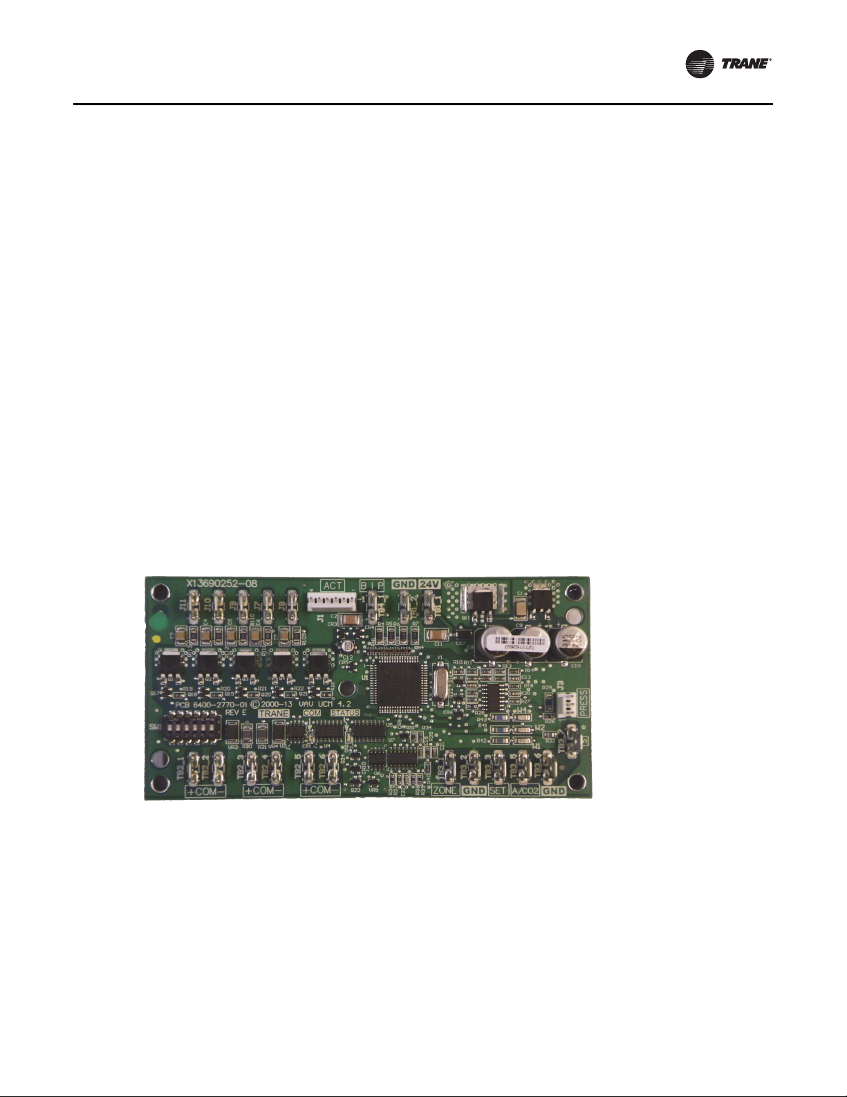
Wiring Diagram
Figure 3, p. 14 shows a typical wiring diagram for the
redesigned UCM hardware.The new service part number
is BRD04939.
Figure 1. UCM 4.2 board layout
Zone Sensor, Auxiliary Sensor, and
Thumbwheel Set Point Calibration
If there is adiscrepancy between a measured temperature
and what theUCM reports, a calibrationoffsetvalue can be
edited in the UCM setup screen to correct the displayed
value.
Flow Sensor Calibration
If there is a discrepancy between a measured flow and
what the UCMreports,the measured valuecan be entered,
which automatically calculates a calibration multiplier to
correct the displayed value.
Water Valve Override
Each UCM that has proportional or staged hot water heat
outputs can be edited to override the water valve to its
maximum position.
Ventilation Set Points and Ratio Calculation
Set point values needed for a space to satisfy indoor air
quality requirements are provided. A resultant ventilation
ratio can be used to calculate an air handler's outside air
damper minimum position or other control strategies.
VAV-SVX01D-EN 7
Page 8

General Information
Water Heat Output Configuration
UCMs that have hot water heat outputs can be configured
for normally open or normally closed.
Zone Sensor Functions
Zone sensor functions now include: air valve drive to
maximum, use unoccupied set points, timed override, and
cancel timed override.
Slaving of Zone Sensors
Up to three(3) UCM 4.2 may be connected to a single zone
sensor.
Generic UCM Capability
UCM 4.2 can be configured to control non-Trane VAV
boxes.
Shipping
EachVAV product and its service literature are shipped in
the same package. When unpacking, make sure that the
literature is notlost or discardedwith the packing material.
Visually inspect the individual components for obvious
defects or damage. All components are thoroughly
inspected before leaving the factory. Any claims for
damage incurred during shipment must be filed with the
carrier.
Storage
When any component of the VAV system and/or field
installed accessories must be stored for a period of time
prior to being installed, they must be protected from the
elements.The storage location temperature should be
between -40° to 150°F (-40° to 65.6°C) and the relative
humidity should be 10% to 90%, non-condensing.
The warranty will not cover damage to theVAV system or
controls due to negligence during storage. A controlled
indoor environment must be used for storage.
8 VAV-SVX01D-EN
Page 9
VAV Start Up/Check Out Procedure
Chapter Overview
This chapter contains information about the following:
• Unit 4.2 Pre-Power Check-Out
• Light Emitting Diode (LED) Operations
• Zone Sensor Check-Out
UCM 4.2 Pre-Power Check-Out
WARNING
Live Electrical Components!
During installation, testing, servicing and
troubleshooting of this product, it may be necessary to
work with live electrical components. Have a qualified
licensed electrician or other individual who has been
properly trained in handling live electrical components
perform these tasks. Failure to follow all electrical
safety precautions when exposed to live electrical
components could result in death or serious injury.
• Check the supply voltage atTB1. Proper polarity must
be maintained.TB1-1 is the hot side (+) andTB1-2 is the
ground side (-) of the 24 VAC input.The UCM cannot be
powered from a common 24 VAC transformer that is
supplying power to a device containing a full-wave
rectifier bridge in its power supply.The acceptable
voltage is 20 to 28 VAC (24 VAC cataloged). However,
voltages at either extreme may result in increased
system instability.
• Verify that communications wiring has properly been
terminated atTB2-1 (+) andTB2-2 (-). Polarity is very
important on the communications link.
• Verify that the zone sensor connections are correct as
detailed in the UCM wiring chapter.
• Verify that the proper unit DIP switch settings have
been set on each UCM.
• Verify that the tubing is properly connected to the
transducer.
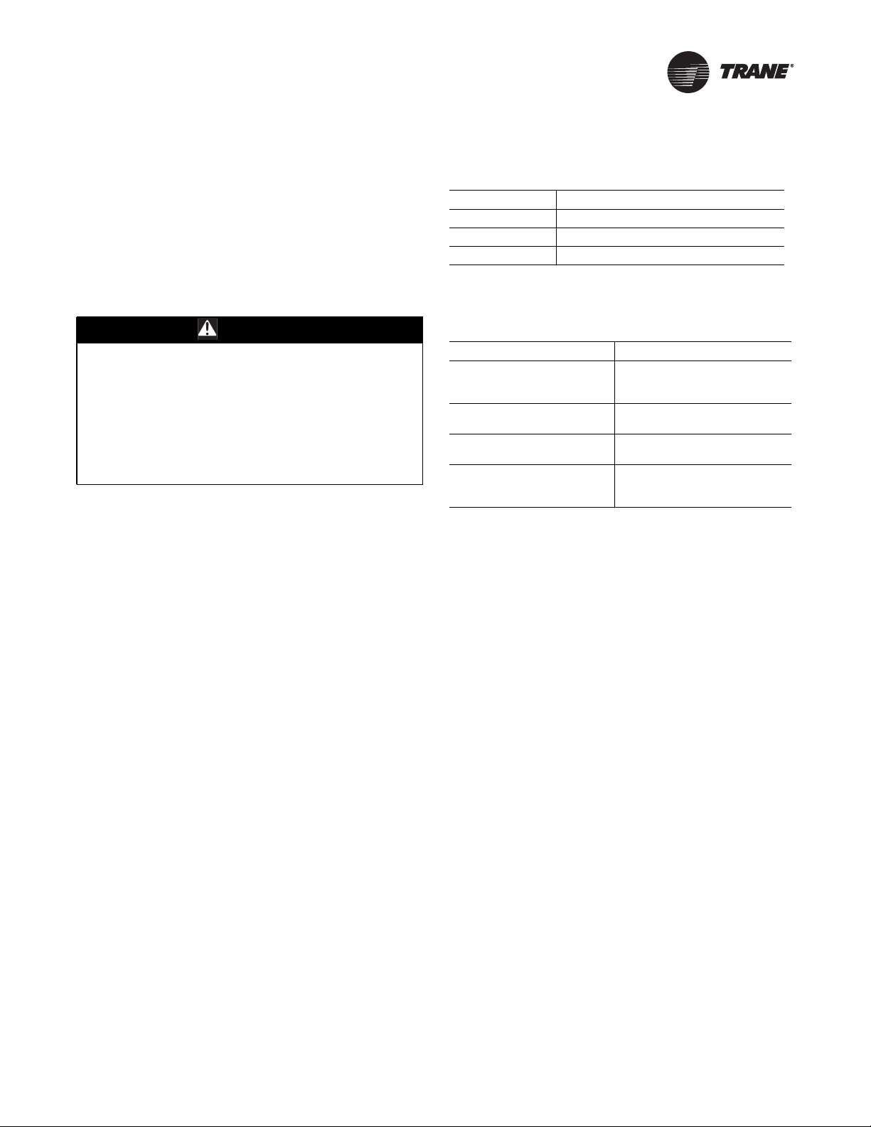
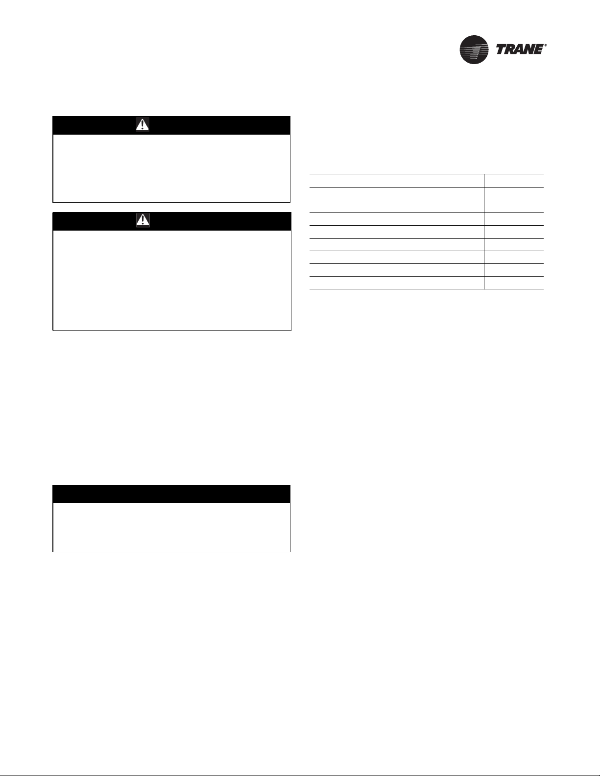
Table 1. Green LED power function indication
LED State Indication
"On” Board functioning correctly
Blinking Board malfunction (Replace Board)
"Off” Board does not have power
The yellow LED functions as the communication indicator.
The indication from the yellow LED is as follows:
:
Table 2. Yellow LED communication indicator function
LED State Indication
"On”
Blinking slowly approx. 1 blink/
sec.
Blinking quickly (multiple blinks/
sec.)
"Off”
Incorrect (reversed)
communication polarity, no
connection, or shorted lines.
Communication is occurring on the
link but not for that particular UCM.
Communication is occurring on the
link, specifically with that UCM.
Polarity is correct and no
communication is occurring on the
link
Light Emitting Diode (LED) Operations
The UCM has one green LED located nearTB3 and one
yellow LED located nearTB2 on the UCM circuit board.
These LED’s are used to help diagnose communication
(yellow) or circuit board problems (green).
The green LED (red on older boards) is a power indicator.
It is steady on when the power is on and the software is
functioning correctly. If it blinks with a 1 second on 1
second off cycle when power is applied, then the board is
not functioning and must be replaced.
VAV-SVX01D-EN 9
Page 10
VAV Start Up/Check Out Procedure
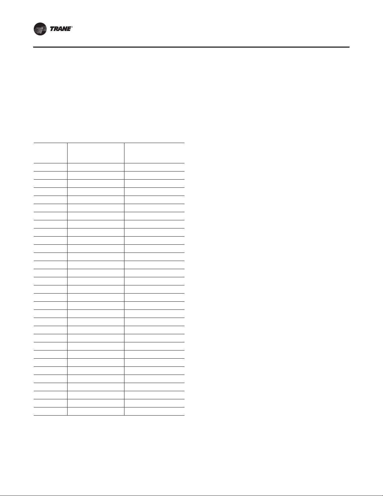
Zone Sensor Check-out
If an erroneous temperature isbeing reported to theUCM,
use the “Zone sensor temperature-resistance table,” p. 10
to verify the integrity of the adjustable set point
potentiometer or sensor.The resistance should be
measured across the terminals to which the device is
connected.
Note: Disconnect the zone sensor from the UCM when
making the checks listed in the table below.
Table 3. Zone sensor temperature-resistance table
Thermostat
Temp (°F)
55 792 17.0
56 772 16.5
57 753 16.1
58 733 15.7
59 714 15.4
60 694 15.0
61 675 14.6
62 656 14.3
63 636 14.0
64 617 13.6
65 597 13.3
66 578 13.0
67 558 12.6
68 539 12.3
69 519 12.1
70 500 11.8
71 481 11.5
72 461 11.2
73 442 11.0
74 422 10.7
75 403 10.4
76 383 10.2
77 364 10.0
78 344 9.7
79 325 9.5
80 306 9.3
81 286 9.0
82 267 8.8
83 247 8.6
84 228 8.4
85 208 8.2
Note: Thumbwheel resistance checks are made at TB3-2 and TB3-3 on the
zone sensor. Temperature sensor resistance is measured at TB3-1
and TB3-2 of the zone sensor.
Thumbwheel
Resistance (Ohms)
Sensor Resistance (k
Ohms)
10 VAV-SVX01D-EN
Page 11
UCM 4.2 Installation and Wiring
UCM power requirement, add the power consumption per
WARNING
Hazardous Voltage!
Disconnect all electric power, including remote
disconnects before servicing. Follow proper lockout/
tagout procedures to ensure the power can not be
inadvertently energized. Failure to disconnect power
before servicing could result in death or serious injury.
WARNING
Proper FieldWiring and Grounding
Required!
All field wiring MUST be performed by qualified
personnel. Improperly installed and grounded field
wiring poses FIRE and ELECTROCUTION hazards. To
avoid these hazards, you MUST follow requirements for
field wiring installation and grounding as described in
NEC and your local/state electrical codes. Failure to
follow code could result in death or serious injury.
Chapter Overview
This chapter contains information about the following:
• UCM 4.2 Power Wiring
• Zone Sensor Wiring
• Communication Wiring
• DIP Switch Settings Selection
UCM 4.2 Power Wiring
Power Requirements
NOTICE:
Use Copper Conductors Only!
Unit terminals are not designed to accept other types
of conductors. Failure to use copper conductors could
result in equipment damage.
Use at least 16 AWG for power wiring and connect to
terminalTB1-1 (+) andTB1-2 (-). 24 VAC is required to
power the UCM control and has an acceptable voltage
tolerance of 20 to 28 VAC. Replace the UCM control box
cover after field wiring to prevent any electromagnetic
interference.
Note: A dedicated 24 VAC, 50VA NEC class 2 transformer
is recommended to power the UCM. When
powering multiple UCM’s from one transformer,
polarity must be maintained.TerminalTB1-1 is
designated positive (+) and terminalTB1-2 is
negative (-) to the unit casing ground.
The power consumption for cooling only Series F Models
(VariTrac andVariTrane) is 12 VA (4 VA for the air valve/
actuator and 8 VA for the board).To determine the total
VAV-SVX01D-EN 11
stage to the circuit board power requirement. For
example, a Series F unit containing magnetic contactors
with three stages of reheat would consume 42 VA.
Table 4. VA rating for components
Style Volt Amps
F - Style Actuator 4 VA
Air Valve Actuator C through E Style 12 VA
Varitrac Actuator 3 VA
Fan Power Fan Output 6 VA
Hot Water Proportional 4 VA
Hot Water 2 Position 6.5 VA
Electric Heater Magnetic Contactor 10 VA
Electric Heater Mercury Contactor 12 VA
Note: VariTrane™ and VariTrac™ cooling only Series D
and E models consume 20 VA (12VA for the
actuator and 8VA for the UCM).The heating output
ratings remain the same.
See Figure 1,p. 7 for UCM terminallocations and Figure 2,
p. 13 through Figure 5, p. 16 for wiring of output devices.
Zone Sensor Wiring
Location and Mounting
A zone sensorin each control zone should belocated in the
most critical area of the zone. Sensors should not be
mounted in direct sunlight or in the area’s supply air
stream. Subdivision of the zone may be necessary for
adequate control and comfort.
Avoid mounting zone sensors in areas subject to the
following:
• Drafts or “dead spots” behind doors or corners
• Hot or cold air ducts
• Radiant heat from the sun or appliances
• Concealed pipes or chimneys
• Unheated or uncooled surfaces behindthe sensor such
as outside walls
• Air flows from adjacent zones or other units
Wiring
Each unit must be controlled by a zone sensor that is
designated specifically for use with the UCM control.Field
wiring for the zone sensors must meet the following
requirements:
• Must be 14 to 18 AWG
• Refer to the sensor instructions for terminal
connections.
• If local codes require enclosed conductors, the zone
sensor wires should be installed in conduit. Do not
Page 12

UCM 4.2 Installation andWiring
route zone sensorwires in conduitwith 24VAC or other
high power conducting wires.
Multiple UCM’s Per Zone Sensor
Up to three (3) UCM’s may be connected to a single zone
sensor and thumbwheel set point.
• Connect terminal connectionsTB3-1,TB3-2, andTB33 in parallel (i.e. daisy chain) from the master UCM to
the slaved UCM(s).
Note: Proper polarity must be maintained.
• Cut jumper wires W1 and W2 on the slaved UCM’s
(never cut jumper wires W1 and W2 on master UCM).
Multiple UCM’s per Auxiliary Duct
Temperature Sensor
Up to three (3) UCMs may be connected to a single
auxiliary duct temperature sensor.
• Connect terminal connectionsTB3-5 andTB3-6 in
parallel (i.e. daisy chain) from the master UCM to the
slaved UCM(s).
Note: Proper polarity must be maintained.
• Cut jumper wire W4 on the slaved UCMs (never cut
jumper wire W4 on the master UCM).
Zone Sensor Hardwired Option
Depending on the zone sensor options used, a maximum
of five wires may be required to run from the UCM to the
zone sensor. The zone sensor options are:
• Zone sensor only (2 wires) - Part Number
X13511528010
• Sensor with night set back - Part Number
X13511530010
• Zone sensor with external adjustable - Part Number
X13511529010
• Zone sensor with external adjustable night set back,
timed override (TOV) on/cancel button - Part Number
X13511527010
• Digital zone sensor - Part Number X13790866010
• Communications jack - Part Number X13651467020
(for one box of 12)
Note: All wiring from the zone sensor to the
Communication link must be twisted shielded pair
wiring.
Zone Sensor Wireless Option
Wireless Zone Sensor
Receiver is used to receive a signal from the wireless zone
sensor and can be factory installed- Part Number
X13790855010.
The wiring harness connects the receiver to the UCM 4.2
- Part Number X19051692010.
Zone Sensor
The wireless zone sensor with night setback timed
override (TOV) on/cancel button. Also can be ordered for
Celsius and Fahrenheit setpoint adjustment - Part Number
X13790492010 (F), X13790494010 (C). DigitalWireless Part
Number: X13790822010.
Communication Wiring
Communication Link Wiring
The “Communication Link” is the communication wiring
betweenTracer Summit® and all VAV box Unit Control
Modules (UCM).Tracer Summit can be connected to the
UCM communication link in a“daisy chain” configuration.
Note: It is not necessary for each UCM to beconnected to
the line in sequential order by address. Also,
multiple communication links may be run and
terminated atTracer Summit. However, a
consistent, documented wiring path will help
troubleshoot communication problems after
installation.
Field wiring for the communication link must meet the
following requirements:
1. Communication link wiring must be at least 18 AWG
twisted shielded pair wire. Shields must be grounded
atTracer Summit or Central Control Panel (CCP) only.
More than one ground reference will cause
communications failures. Shields must be daisy
chained.Tape the shield at the lastVAV UCM to prevent
any connection between the shield and ground. Wire
specifications are as follows:
Plenum Cable
Stranded, tinned copper insulated with extruded FEP.
Conductors cabled and shielded with overall
aluminum/Mylar tape and stranded, tinned copper
drawn wire. Extruded jacket, 300 volt, 150°C NEC 7252 (b) class 2, type CL2P, 25 pF/ft.
Non-Plenum Cable
Stranded tinned copper insulated with polyethylene.
Conductors cabled and shielded with overall
aluminum/polyester tape and stranded, tinned copper
drain wire. Chrome gray PVC jacket, 300V, 60°C NEC
type CM, 24 pF/ft.
Table 5. Wire capacitance
Max. Communication
Link Wiring Length Max. Wire Capacitance
1,000 feet (304.8m) Up to 60 pF/ft. (196.9 pF/m)
2,000 feet (609.6 m) Up to 50 pF/ft. (164.0 pF/m)
3,000 feet (914.4m) Up to 40 pF/ft. (131.2 pF/m)
4,000 feet (1,219.2 m) Up to 30 pF/ft. (98.4 pF/m)
5,000 feet (1,524 m) Up to 25 pF/ft. (82.0 pF/m)
Note: Wire capacitance must comply with this table.
12 VAV-SVX01D-EN
Page 13
UCM 4.2 Installation andWiring
2. The maximum wire length should not exceed 5,000
feet (1,524 m).
3. Communication link wiring cannot pass between
buildings.
4. A maximum of 63 UCMs can be connected to each
COM Link. Daisy chaining is a typical configuration.
“STAR” chaining is also acceptable.
Note: Polarity is extremely important and must be
observed on communication link connections.
5. At the VAV box, communication link wires must be
connected toTB2-1, 3 (+) andTB2-2, 4 (-) terminals on
the UCM.
6. Verify that the UCM address is properly set (DIP switch
SW1). See
Table 6, p. 13 for proper DIP switch settings.
DIP Switch Settings
DIP Switch SW1 contains six switches for addressing the
UCM.These switches allow a user to set a unique
communication address for each UCM. Each UCM on a
given communication link must have a unique address in
order forTracer Summit or the CCP to communicate to it.
Refer to Table 6, p. 13 for UCM 4.2 DIP switch settings.
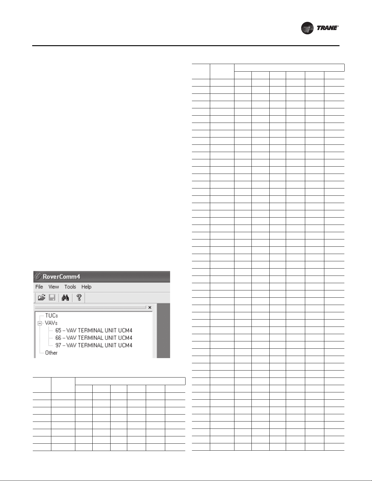
Note: When using Rover™ service tool to communicate
to the UCM, you must add 64 to the DIP switch
address. For example, a UCM with the DIP switch
address set to 1 would be UCM Number 65 in
Rover.
Figure 2. Rover screen/application
Table 6. DIP switch settings for UCM 4.2
UCM
Unit #
Address 1 2 3 4 5 6
1 65 OFF ON ON ON ON ON
2 66 ON OFF ON ON ON ON
3 67 OFF OFF ON ON ON ON
4 68 ON ON OFF ON ON ON
5 69 OFF ON OFF ON ON ON
6 70 ON OFF OFF ON ON ON
7 71 OFF OFF OFF ON ON ON
8 72 ON ON ON OFF ON ON
Dip
Table 6. DIP switch settings for UCM 4.2 (continued)
UCM
Unit #
Address 1 2 3 4 5 6
9 73 OFF ON ON OFF ON ON
10 74 ON OFF ON OFF ON ON
11 75 OFF OFF ON OFF ON ON
12 76 ON ON OFF OFF ON ON
13 77 OFF ON OFF OFF ON ON
14 78 ON OFF OFF OFF ON ON
15 79 OFF OFF OFF OFF ON ON
16 80 ON ON ON ON OFF ON
17 81 OFF ON ON ON OFF ON
18 82 ON OFF ON ON OFF ON
19 83 OFF OFF ON ON OFF ON
20 84 ON ON OFF ON OFF ON
21 85 OFF ON OFF ON OFF ON
22 86 ON OFF OFF ON OFF ON
23 87 OFF OFF OFF ON OFF ON
24 88 ON ON ON OFF OFF ON
25 89 OFF ON ON OFF OFF ON
26 90 ON OFF ON OFF OFF ON
27 91 OFF OFF ON OFF OFF ON
28 92 ON ON OFF OFF OFF ON
29 93 OFF ON OFF OFF OFF ON
30 94 ON OFF OFF OFF OFF ON
31 95 OFF OFF OFF OFF OFF ON
32 96 ON ON ON ON ON OFF
33 97 OFF ON ON ON ON OFF
34 98 ON OFF ON ON ON OFF
35 99 OFF OFF ON ON ON OFF
36 100 ON ON OFF ON ON OFF
37 101 OFF ON OFF ON ON OFF
38 102 ON OFF OFF ON ON OFF
39 103 OFF OFF OFF ON ON OFF
40 104 ON ON ON OFF ON OFF
41 105 OFF ON ON OFF ON OFF
42 106 ON OFF ON OFF ON OFF
43 107 OFF OFF ON OFF ON OFF
44 108 ON ON OFF OFF ON OFF
45 109 OFF ON OFF OFF ON OFF
46 110 ON OFF OFF OFF ON OFF
47 111 OFF OFF OFF OFF ON OFF
48 112 ON ON ON ON OFF OFF
49 113 OFF ON ON ON OFF OFF
50 114 ON OFF ON ON OFF OFF
51 115 OFF OFF ON ON OFF OFF
52 116 ON ON OFF ON OFF OFF
53 117 OFF ON OFF ON OFF OFF
54 118 ON OFF OFF ON OFF OFF
55 119 OFF OFF OFF ON OFF OFF
56 120 ON ON ON OFF OFF OFF
57 121 OFF ON ON OFF OFF OFF
58 122 ON OFF ON OFF OFF OFF
59 123 OFF OFF ON OFF OFF OFF
Dip
VAV-SVX01D-EN 13
Page 14
UCM 4.2 Installation andWiring
Table 6. DIP switch settings for UCM 4.2 (continued)
UCM
Unit #
Address 1 2 3 4 5 6
60 124 ON ON OFF OFF OFF OFF
61 125 OFF ON OFF OFF OFF OFF
62 126 ON OFF OFF OFF OFF OFF
63 127 OFF OFF OFF OFF OFF OFF
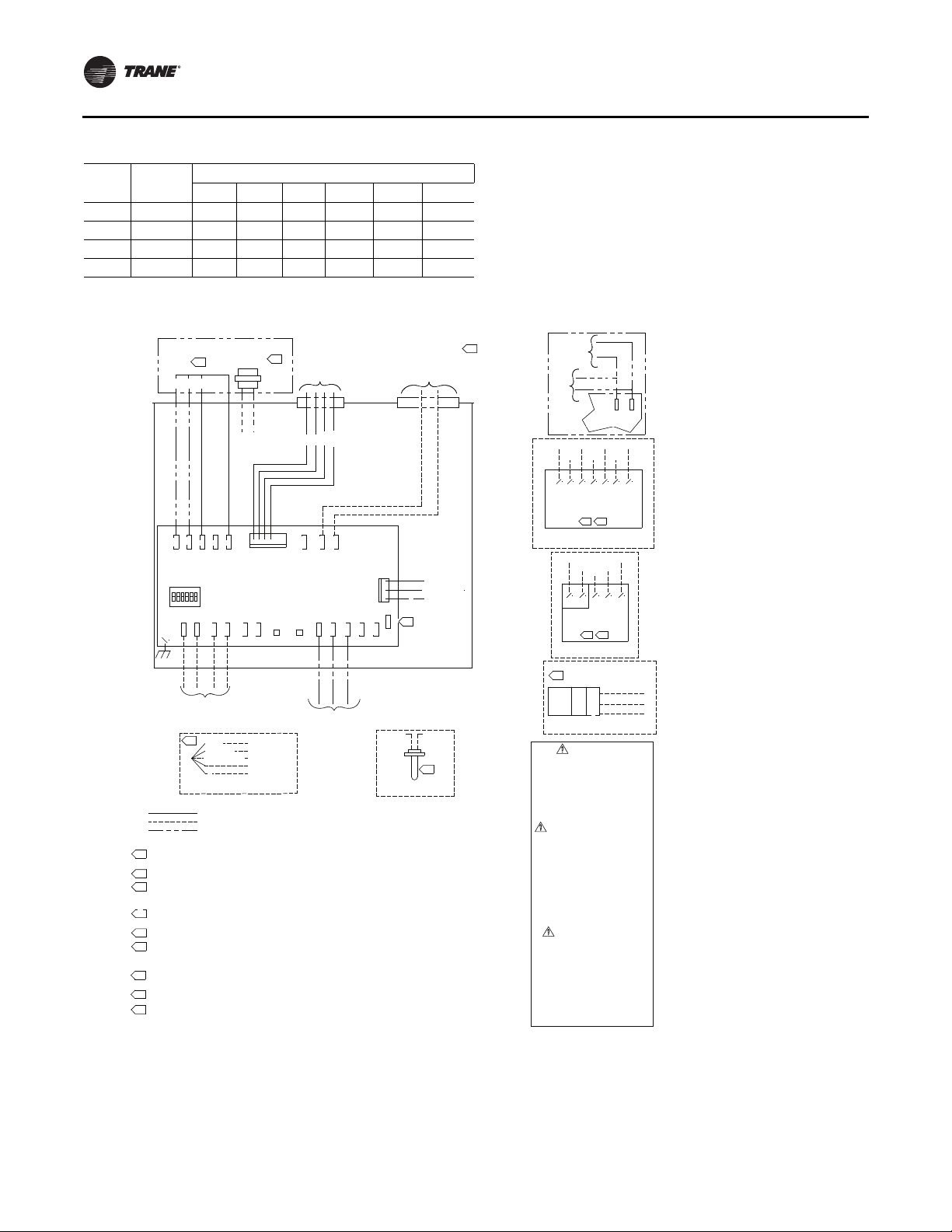
Figure 3. Wiring diagram for single duct units with factory installed electric reheat
Dip
The following figures show wiring diagrams for typical
applications of UCM 4.2
.
HEATER STAGE
CONTACTOR(S)
3RD 2ND
3RD STG.
R
J11
ADDRESS
SWITCH
+ -
TB2-1
IN
SHIELDED TWISTED PAIR
COMMUNICATIONS WIRING
NOTE:
1.
2.
1/4" QUICK CONNECT REQUIRED FOR ALL FIELD CONNECTIONS.
3.
ZONE SENSOR TERMINALS 1 (-) AND 2 (+) REQUIRE SHIELDED TWISTED PAIR
WIRING FOR COMMUNICATIONS JACK EQUIPPED ZONE SENSOR OPTION.
4.
NO ADDITIONAL WIRING REQUIRED FOR NIGHT SETBACK OVERRIDE (ON/CANCEL).
5.
THE OPTIONAL BINARY INPUT CONNECTS BETWEEN TB4-1 (BIP) AND 24VAC (HOT) FROM
TRANSFORMER. THE BINARY INPUT CAN BE RECONFIGURED AS AN OCCUPANCY INPUT VIA THE
COMMUNICATIONS INTERFACE.
6.
AS SHIPPED, THE AUX INPUT IS CONFIGURED AS AN AUX TEMP INPUT. THE AUX INPUT CAN BE
RECONFIGURED AS A CO2 SENSOR INPUT VIA THE COMMUNICATIONS INTERFACE.
7.
S TERMINAL NOT TO BE USED WITH VARITRANE.
IF UNIT MOUNTED TRANFORMER IS NOT PROVIDED, POLARITY FROM UNIT TO UNIT MUST BE
8.
MAINTAINED TO PREVENT PERMANENT DAMAGE TO CONTROL BOARD. IF ONE LEG OF 24VAC
SUPPLY IS GROUNDED, THEN GROUND LEG MUST BE CONNECTED TO TB1-2.
CONTACTORS ARE 24 VAC: 12VA MAX/COIL (MERCURY CONTACTORS). 10VA MAX/COIL
9.
(MAGNETIC CONTACTORS)
10.
OPTIONAL FUSE, DISCONNECT SWITCH & TRANSFORMER LOCATED IN HEATER.
ZONE SENSOR TERMINALS 6 AND 7 REQUIRE SHIELDED TWISTED PAIR
11.
WIRING FOR OPTIONAL USE OF COMMUNICATIONS JACK.
OPTIONAL
9.
TRANSFORMER
1ST
HOT
1ST STG.
2ND STG.
V
J10
Y
-2
O
TB1
BR
J1
J7
J8
J9
CONTROL BOARD
+
-
+ -
-4
TB2-3
TB2-5
TB2
TB2-2
IN
OUT
OUT
5.
R (HOT)
O (COMMON)
GR (NC CONTACT)
BK (RETURN)
Y
OPTIONAL FIELD INSTALLED
OCCUPANCY SENSOR
FACTORY WIRING
FIELD WIRING
OPTIONAL OR ALTERNATE WIRING
BL
1-1
B
T
D.D.C.\U.C.M.
TB2-6
(TB1-1) 24VAC
(TB4-1) BIP
(TB1-1) 24VAC
(TB1-2) GND
NOT CONNECTED
DAMPER
10.
ACTUATOR
WIRING
T
PEN
O
HOT
HO
CLOSE
1
1-2
4-1
B
T
TB1-1
TB
ACT
YEL GRN
OPTIONAL FACTORY INSTALLED
BIP
GND
ZONE
TB3-1
WIRELESS
24V
GND A/CO2
-2
TB3
-5
3-3
TB3
TB
J3
PRESS
1
GNDSET
6
TB3-
TB3-5
AUX TEMP SENSOR
24VAC 60HZ
NEC CLASS-2
CONTROL CIRCUIT
LOAD= 12VA
(WITHOUT HEAT)
PRESSURE
TRANSDUCER
R
+
BK
VOUT
G
-
S
7.
D.D.C.\U.C.M.
CONTROL BOX
TB3-6
6.
OPTIONAL
UCM or EI Board
TB3-3
TB2-5
11.
TB3-3
3.
DUCT
MOUNTED
MOUNTED
+
0
V
Y
TB3-2
3 2 1
TB3-2
2 1
4.
(TB1-1) 24V
(TB3-6) GND
(TB3-5) A/CO2
BL
Y
BL
1-1
TB1-2
TB
24V
GND
TB3-1
TB3-1
OPTIONAL
8.
FACTORY
INSTALLED
WIRELESS
24VAC
TB2-6
TB1-1
TB1-2
114.710 6
DIGITAL DISPLAY ZONE SENSOR
W/ COMM. JACK
REMOTE MTD.
OPTIONAL FIELD INSTALLED
DIGITAL DISPLAY ZONE SENSOR
TB2-6
TB2-5
1(-)2(+) 3
ZONE SENSOR
W/ COMM. JACK
REMOTE MTD.
OPTIONAL FIELD
INSTALLED ZONE SENSOR
LL
6.
WA
24V
CO2
GND
SENSOR
OUT
OPTIONAL FIELD INSTALLED
CO2 SENSOR
WARNING
HAZARDOUS VOLTAGE!
DISCONNECT ALL ELECTRIC POWER
INCLUDING REMOTE DISCONNECTS AND
FOLLOW LOCK OUT AND TAG PROCEDURES
BEFORE SERVICING. INSURE THAT ALL
MOTOR CAPACITORS HAVE DISCHARGED
STORED VOLTAGE. UNITS WITH VARIABLE
SPEED DRIVE, REFER TO DRIVE
INSTRUCTIONS FOR CAPACITOR DISCHARGE.
FAILURE TO DO THE ABOVE COULD RESULT
IN DEATH OR SERIOUS INJURY.
AVERTISSEMENT
TENSION DANGEREUSE!
COUPER TOUTES LES TENSIONS ET
OUVRIR LES SECTIONNEURS À DISTANCE,
PUIS SUIVRE LES PROCÉDURES DE
VERROUILLAGE ET DES ÉTIQUETTES AVANT
TOUTE INTERVENTION. VÉRIFIER QUE TOUS
LES CONDENSATEURS DES MOTEURS SONT
DÉCHARGÉS. DANS LE CAS D'UNITÉS
COMPORTANT DES ENTRAÎNEMENTS À
VITESSE VARIABLE, SE REPORTER AUX
INSTRUCTIONS DE L'ENTRAÃŽNEMENT POUR
DÉCHARGER LES CONDENSATEURS.
NE PAS RESPECTER CES MESURES DE
PRÉCAUTION PEUT ENTRAÎNER DES
BLESSURES GRAVES POUVANT ÊTRE
MORTELLES.
ADVERTENCIA
iVOLTAJE PELIGROSO!
DESCONECTE TODA LA ENERGÃA ELÉCTRICA,
INCLUSO LAS DESCONEXIONES REMOTAS Y
SIGA LOS PROCEDIMIENTOS DE CIERRE Y
ETIQUETADO ANTES DE PROCEDER AL
SERVICIO. ASEGÚRESE DE QUE TODOS
LOS CAPACITORES DEL MOTOR HAYAN
DESCARGADO EL VOLTAJE ALMACENADO.
PARA LAS UNIDADES CON TRANSMISIÓN
DE VELOCIDAD VARIABLE, CONSULTE LAS
INSTRUCCIONES PARA LA DESCARGA
DEL CONDENSADOR.
EL NO REALIZAR LO ANTERIORMENTE
INDICADO, PODRÃA OCASIONAR LA MUERTE
O SERIAS LESIONES PERSONALES.
14 VAV-SVX01D-EN
Page 15
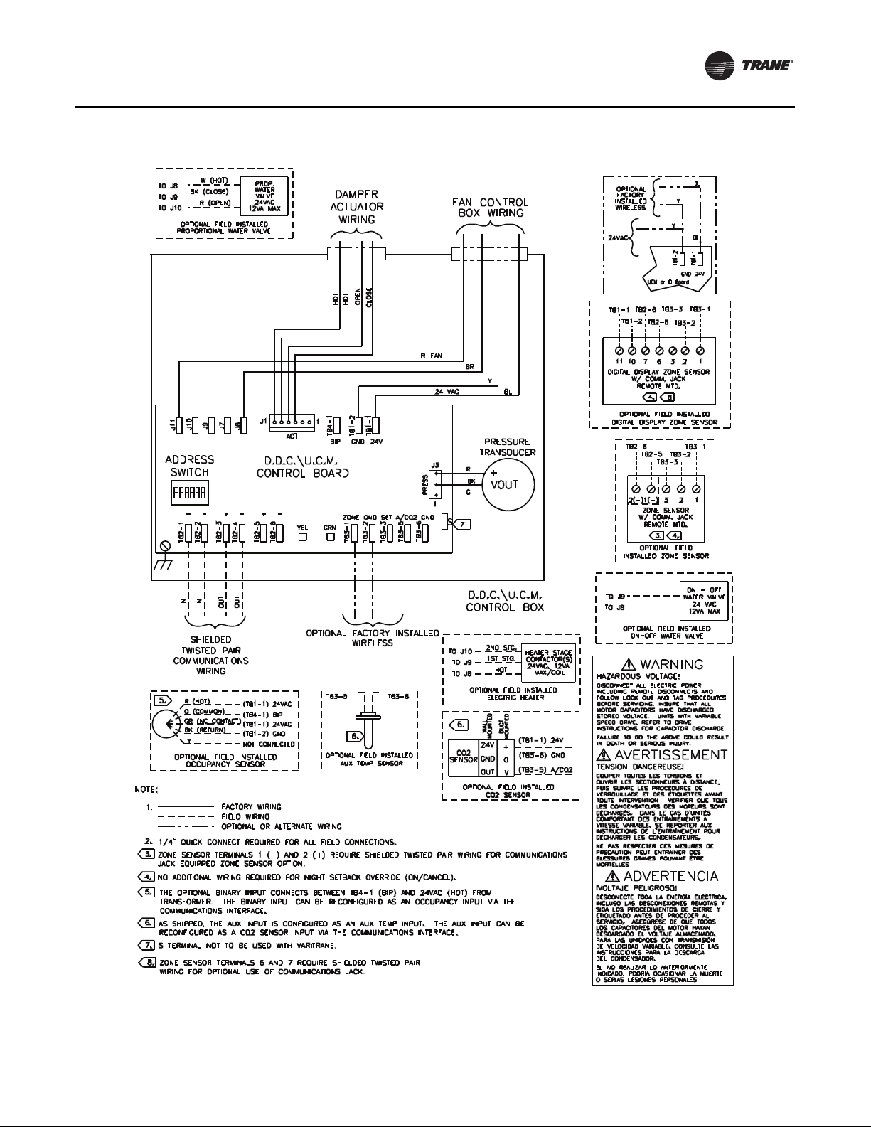
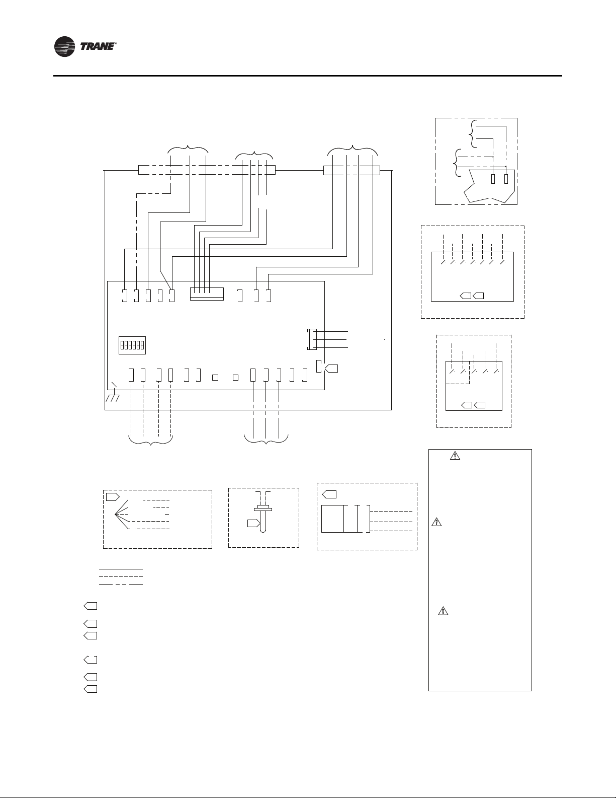
Figure 4. Wiring diagram for fan-powered units with field installed reheat
UCM 4.2 Installation andWiring
VAV-SVX01D-EN 15
Page 16
UCM 4.2 Installation andWiring
Figure 5. Wiring diagram for fan-powered units with factory installed electric reheat
2ND STG HEAT
V
J10
J11
ADDRESS
SWITCH
+ - +
TB2-2
TB2-1
IN
1ST STG HEAT
O
J9
IN
HEATER
TERMINAL
BOX WIRING
J7
J8
- +
B2-4
T
TB2-3
T
OU
OUT
ACTUATOR
BR-HOT
J1
ACT
1
B4-1
T
BIP
D.D.C.\U.C.M.
CONTROL BOARD
-
YEL
2-5
B
TB2-6
T
GRN
DAMPER
WIRING
OT
OPEN
HOT
H
TB1-2
GND
ZONE SETGND
3-1
B
T
TB3-3
6.
TB3-2
3 2
Y
Y
TB1-2
GND
TB3-2
3 2 1
TB3-1
1
TB3-1
BL
BL
1-1
B
T
24V
OPTIONAL
FAN CONTROL
BOX WIRING
E
LOS
C
R-FAN
1-1
B
T
24V
A/CO2
GND
3-3
B3-5
B
B3-2
T
TB3-6
T
T
ESS
PR
24 VAC
J3
1
S
BR
TRANSDUCER
R
BK
G
7.
Y
BL
PRESSURE
+
VOUT
-
D.D.C.\U.C.M.
CONTROL BOX
FACTORY
INSTALLED
WIRELESS
24VAC
UCM or EI Board
TB2-6
TB1-1
TB1-2
TB2-5
11
10 7 6
DIGITAL DISPLAY ZONE SENSOR
W/ COMM. JACK
REMOTE MTD.
4.
OPTIONAL FIELD INSTALLED
DIGITAL DISPLAY ZONE SENSOR
TB2-6
TB2-5
TB3-3
1(-)2(+)
ZONE SENSOR
W/ COMM. JACK
REMOTE MTD.
3. 4.
OPTIONAL FIELD
INSTALLED ZONE SENSOR
SHIELDED
TWISTED PAIR
COMMUNICATIONS
WIRING
5.
R (HOT)
O (COMMON)
GR (NC CONTACT)
BK (RETURN)
Y
OPTIONAL FIELD INSTALLED
OCCUPANCY SENSOR
(TB1-1) 24VAC
(TB4-1) BIP
(TB1-1) 24VAC
(TB1-2) GND
NOT CONNECTED
OPTIONAL FACTORY INSTALLED
WIRELESS
TB3-6TB3-5
6.
OPTIONAL
AUX TEMP SENSOR
SENSOR
NOTE:
1.
1/4" QUICK CONNECT REQUIRED FOR ALL FIELD CONNECTIONS.
2.
3.
ZONE SENSOR TERMINALS 1 (-) AND 2 (+) REQUIRE SHIELDED TWISTED PAIR WIRING FOR COMMUNICATIONS
JACK EQUIPPED ZONE SENSOR OPTION.
4.
NO ADDITIONAL WIRING REQUIRED FOR NIGHT SETBACK OVERRIDE (ON/CANCEL).
5.
THE OPTIONAL BINARY INPUT CONNECTS BETWEEN TB4-1 (BIP) AND 24VAC (HOT) FROM TRANSFORMER.
THE BINARY INPUT CAN BE RECONFIGURED AS AN OCCUPANCY INPUT VIA THE COMMUNICATIONS
INTERFACE.
6.
AS SHIPPED, THE AUX INPUT IS CONFIGURED AS AN AUX TEMP INPUT. THE AUX INPUT CAN BE
RECONFIGURED AS A CO2 SENSOR INPUT VIA THE COMMUNICATIONS INTERFACE.
7.
S TERMINAL NOT TO BE USED WITH VARITRANE.
8.
ZONE SENSOR TERMINALS 6 AND 7 REQUIRE SHIELDED TWISTED PAIR WIRING FOR COMMUNICATIONS
JACK EQUIPPED ZONE SENSOR OPTION.
FACTORY WIRING
FIELD WIRING
OPTIONAL OR ALTERNATE WIRING
6.
WALL
DUCT
MOUNTED
MOUNTED
24V
GND
OUT
CO2 SENSOR
+
0
V
(TB3-6) GND
CO2
OPTIONAL FIELD INSTALLED
(TB1-1) 24V
(TB3-5) A/CO2
HAZARDOUS VOLTAGE!
DISCONNECT ALL ELECTRIC POWER
INCLUDING REMOTE DISCONNECTS AND
FOLLOW LOCK OUT AND TAG PROCEDURES
BEFORE SERVICING. INSURE THAT ALL
MOTOR CAPACITORS HAVE DISCHARGED
STORED VOLTAGE. UNITS WITH VARIABLE
SPEED DRIVE, REFER TO DRIVE
INSTRUCTIONS FOR CAPACITOR DISCHARGE.
FAILURE TO DO THE ABOVE COULD RESULT
IN DEATH OR SERIOUS INJURY.
TENSION DANGEREUSE!
COUPER TOUTES LES TENSIONS ET
OUVRIR LES SECTIONNEURS À DISTANCE,
PUIS SUIVRE LES PROCÉDURES DE
VERROUILLAGE ET DES ÉTIQUETTES AVANT
TOUTE INTERVENTION. VÉRIFIER QUE TOUS
LES CONDENSATEURS DES MOTEURS SONT
DÉCHARGÉS. DANS LE CAS D'UNITÉS
COMPORTANT DES ENTRAÎNEMENTS À
VITESSE VARIABLE, SE REPORTER AUX
INSTRUCTIONS DE L'ENTRAÃŽNEMENT POUR
DÉCHARGER LES CONDENSATEURS.
NE PAS RESPECTER CES MESURES DE
PRÉCAUTION PEUT ENTRAÎNER DES
BLESSURES GRAVES POUVANT ÊTRE
MORTELLES.
iVOLTAJE PELIGROSO!
DESCONECTE TODA LA ENERGÃA ELÉCTRICA,
INCLUSO LAS DESCONEXIONES REMOTAS Y
SIGA LOS PROCEDIMIENTOS DE CIERRE Y
ETIQUETADO ANTES DE PROCEDER AL
SERVICIO. ASEGÚRESE DE QUE TODOS
LOS CAPACITORES DEL MOTOR HAYAN
DESCARGADO EL VOLTAJE ALMACENADO.
PARA LAS UNIDADES CON TRANSMISIÓN
DE VELOCIDAD VARIABLE, CONSULTE LAS
INSTRUCCIONES PARA LA DESCARGA
DEL CONDENSADOR.
EL NO REALIZAR LO ANTERIORMENTE
INDICADO, PODRÃA OCASIONAR LA MUERTE
O SERIAS LESIONES PERSONALES.
WARNING
AVERTISSEMENT
ADVERTENCIA
16 VAV-SVX01D-EN
Page 17
Wireless Zone Sensor
Overview
TheTraneWireless Zone Sensor set includes a sensor and
a receiver that work together to provide the same
functions as the equivalentTrane wired sensor (#4190-
1090), such as the standard 10 k temperature input (with
the exception of the communication jack). No further
software or hardware is necessary for site evaluation,
installation, or maintenance.
The sensor transmits the zone temperature, all zone
temperature setpoint functions, timed override Occupied
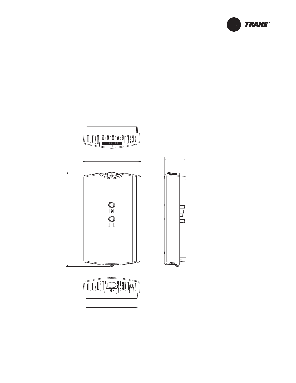
Figure 6. Outside dimensions for sensor
2.90 in (7.35 cm)
(On) and timed override Unoccupied (Cancel) information
to the receiver.The receiver electrically reproduces the
zone temperature resistance, all zone temperature
setpoint function resistances, and timed override On and
timed override Cancel information as sent by the sensor.
Dimensional Diagrams
See Figure 6,p. 17 and Figure 7, p. 18 fordimensions of the
Wireless Zone Sensor set.The dimensions are the same
for both the sensor and the receiver.
1.08 in (2.75 cm)
4.78 in (12.14 cm)
2.62 in (6.65 cm)
Note: The dimensions are the
same for both the sensor
and the receiver.
VAV-SVX01D-EN 17
Page 18
Wireless Zone Sensor
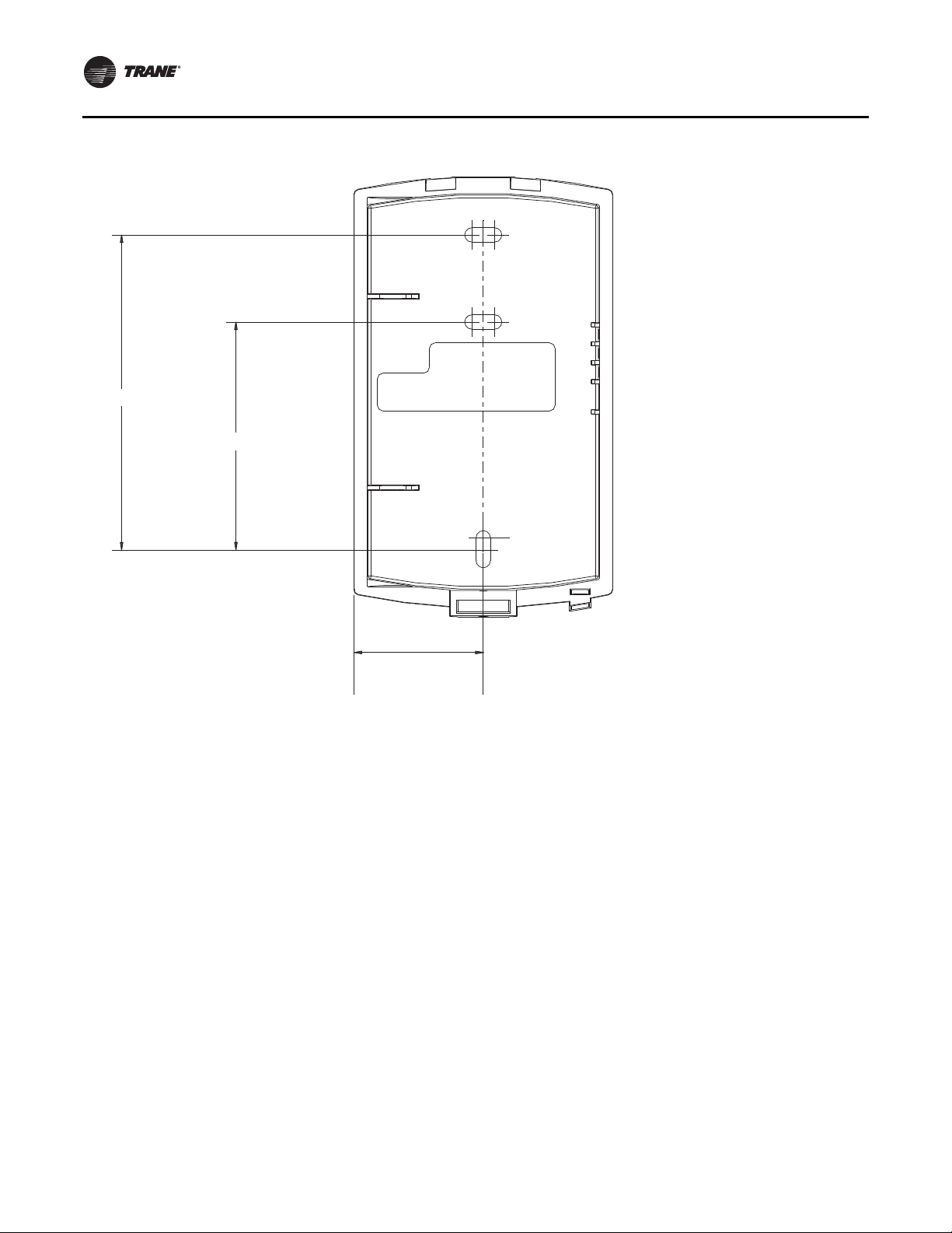
Figure 7. Mounting hole dimensions for sensor
3.27 in (8.30 cm)
2.36 in (6.00 cm)
1.34 in (3.41 cm)
Setting the Address, Mounting,
Wiring, and Associating the
Receiver and Sensor
The following procedure list shows the recommended
order for installation:
• Choosing a location for mounting the sensor
• Settingthe rotary address switches on the receiver and
on the sensor
• Replacing and securing the receiver cover
• Powering the sensor and associating the sensor to the
receiver
• Applying power to the receiver
• Testing signal and battery strength
• Disassociation
Note: The dimensions are the
same for both the sensor
and the receiver.
Choosing a Location for Mounting the Sensor
Placement of the receiver and the sensor set is critical to
proper operation. In most installations, distance is not the
limiting factor for proper radio signal quality. It is more
greatly affected by walls, barriers, and general clutter. For
best radio transmission range and reliability, wherever
possible, mount the receiver andsensor in line of sight.Try
to minimize the number of barriers between the pair of
devices. In general, sheetrock walls and ceiling tiles offer
little restriction to the propagation of the radio signal
throughout the building; concrete or metal barriers offer
the most restriction.Thetransmission range for the sensor
is as follows:
• Open range: 2,500 ft (762 m) (packet error rate = 2%)
• Usable range: 200 ft (61 m)
• Typical range: 75 ft (23 m)
18 VAV-SVX01D-EN
Page 19
Wireless Zone Sensor
DRESS
IN
LED3
L
ED2
T
A
Ambient considerations
Avoidlocations that are outside theoperating temperature
and humidity range (see Table 14, p. 48).
Location Considerations for the Sensor
When selecting a location for the sensor, consider both
thermal and radio transmission characteristics of the
location.
Thermal considerations
• Avoid areas of direct sunlight
• Avoid areas in the direct air stream of air diffusers
• Avoid exterior walls and other walls that have a
temperature differential between their two sides
• Avoid areas close to sources of heat such as sunlight,
appliances, or other equipment
• Avoid drafty areas
• Avoid dead spots behind doors, projection screens, or
corners
Radio transmission considerations
• Avoid placing the sensor inside metal enclosures
• Avoid radio transmissions through thick, solid
concrete walls
Setting the Rotary Address Switches on the Receiver and the Sensor
Note: To expedite the installation and association
process, set the addresses before applying power
to the receiver.
The process of establishing communication between the
receiver and sensor is referred to as association.The
receiver and the sensormust have their rotary switches set
to the same address in order to enable communication
between the two devices (see Figure 8, p. 19). Important
limitations are as follows:
• Only one associated receiver/sensor set can
communicate within the reception range of the
wireless system.
• It is not possible to associate more than one sensor to
a receiver, nor is it possibleto associate morethan one
receiver to a sensor.
• Avoid metal barriers between the sensor and receiver,
such as plastered walls with metal lathe as they will
decrease radio signal quality.
Figure 8. Setting the rotary address switches on the receiver and the sensor
Do not remove the
insulation strip yet.
B1 +
WIRELESS
L
STAL
LED1
LED2
LED3
LED5
SIGNAL
POWER
S5
S1
ADD
HEATING SET
FAN/SYSTEM
5
S
SETPOINT
ZONE
GND
24VAC/DC
GND
COMM +
COMM -
S2
C33
LED4
S4
S3
C34
J1
C35
R77
Setting the Receiver Address
1. Using a small screwdriver, set the three rotaryaddress
switches (locations S1, S2, S3) on the receiver
(Figure 8, p. 19) to an address between 001 and 999.
Note: Do not use 000 as an address for installation. If
you set the receiver address to 000, it will:
– Return the receiver outputs to their factory
defaults indefinitely (zone temperature and
setpoint outputs: 72.5°F [22.5°C])
!
Pb
S1
ADDRESS
Pb-FREE
S3
LED4
S2
STATUS
S4
WIRELESS
INSTALL
LED1
SIGNAL
LED5
BATTERY
STATUS
– Make the receiver unable to associate with a
sensor
• Read the switches from left to right in the order in
which they are numbered (S1, S2, S3).
• Zero is at the 9 o'clock position.
2. Make a notation of the address and location of the
receiver.
– Remove all association knowledge
VAV-SVX01D-EN 19
Page 20

Wireless Zone Sensor
Setting the Sensor Address
1. Using a small screwdriver, set the three rotaryaddress
switches (locations S1, S2, S3) on thesensor (Figure 8,
p. 19) to the same address used for the receiver it is to
be associated with.
2. Make a notation of the address and locationwhere this
sensor is to be mounted.
Note: Do not use 000 as an address for installation. If
you set the address to 000, it will:
– Remove all association knowledge
– Revert to a low-power hibernation mode.
– Send a disassociation request to the receiver. If
the sensor and receiver are associated and
communicating at the time the sensor is set to
000 and theTest button is pressed, the receiver
will also become unassociated and will be
available for re-association.
• Read the switches from left to right in the order in
which they are numbered (S1, S2, S3).
• Zero is at the 9 o'clock position.
3. Make a notation of the address and location of the
sensor.
Factory Wiring of the Receiver to the VAV UCM
The required power for the receiver is 24 VAC or 24 Vdc
and is less than 1 VA.The receiver is designed to be
powered by the VAV UCM controller.
Note: A dedicated transformer is not necessary or
advised.
20 VAV-SVX01D-EN
Page 21
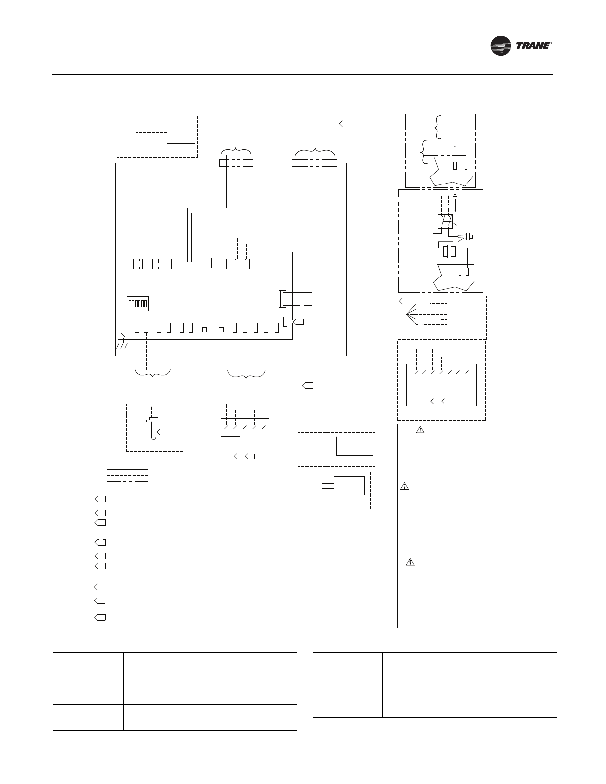
Figure 9. Factory wiring of the receiver to the VAV UCM
Wireless Zone Sensor
W (HOT)
TO J8
BK (CLOSE)
TO J9
R (OPEN)
TO J10
OPTIONAL FIELD INSTALLED
PROPORTIONAL WATER VALVE
J10
J11
ADDRESS
SWITCH
TB2-2
TB2-1
IN
SHIELDED TWISTED PAIR
COMMUNICATIONS WIRING
TB3-5
AUX TEMP SENSOR
NOTE:
1.
2.
1/4" QUICK CONNECT REQUIRED FOR ALL FIELD CONNECTIONS.
3.
ZONE SENSOR TERMINALS 1 (-) AND 2 (+) REQUIRE SHIELDED TW ISTED PAIR
WIRING FOR COMMUNICATIONS JACK EQUIPPED ZONE SENSOR OPT ION.
4.
NO ADDITIONAL WIRING REQUIRED FOR NIGHT SETBACK OVERRIDE (ON/CANCEL).
5.
THE OPTIONAL BINARY INPUT CONNECTS BETW EEN TB4-1 (BIP) AND 24VAC (HOT) FROM
TRANSFORMER. THE BINARY INPUT CAN BE RECONFIGURED AS AN OCCUPANCY INPUT VIA THE
COMMUNICATIONS INTERFACE.
6.
AS SHIPPED, THE AUX INPUT IS CONFIGURED AS AN AUX TEMP INPUT. THE AUX INPUT CAN BE
RECONFIGURED AS A CO2 SENSOR INPUT VIA THE COMMUNICATIONS INTERFACE.
7.
S TERMINAL NOT TO BE USED WIT H VARITRANE.
IF UNIT MOUNTED TRANFORMER IS NOT PROVIDED, POLARITY FROM UNIT TO UNIT MUST BE
8.
MAINTAINED TO PREVENT PERMANENT DAMAGE TO CONT ROL BOARD. IF ONE LEG OF 24VAC
SUPPLY IS GROUNDED, THEN GROUND LEG MUST BE CONNECTED TO TB1-2.
OPTIONAL FUSE, DISCONNECT SWITCH & TRANSFORM ER WIRING. WIRINGS GOES THRU TO
9.
NEXT COMPONENT WHEN OPTIONS ARE NOT CHOSEN/
10.
TRANSFORMER WIRE COLORS: 120V - W, 208V - R, 240V - O, 277V - BR, 480V - R/BK
575V -R, 190V - R, 220V - R, 347V - R.
ZONE SENSOR TERMINALS 6 AND 7 REQUIRE SHIELDED TWISTED PAIR
11.
WIRING FOR OPTIONAL USE OF COMMUNICATIONS JACK.
PROP.
WATER
VALVE
24VAC
12VA MAX
J1
8
J9
J7
J
ACT
D.D.C.\U.C.M.
CONTROL BOARD
+ -+ -
TB2-3
OUTINOUT
TB2-4
TB3-6
-
+
TB2-6
TB2-5
6.
OPTIONAL
FACTORY WIRING
FIELD WIRING
OPTIONAL OR ALTERNATE WIRING
DAMPER
ACTUATOR
WIRING
T
HO
HOT
1
4-1
TB
BIP
GND
ZONE
YEL
GRN
3-1
TB
OPTIONAL FACTORY INSTALLED
WIRELESS
TB2-6
TB2-5
2(+)
ZONE SENSOR
W/ COMM. JACK
REMOTE MTD.
OPTIONAL FIELD
INSTALLED ZONE SENSOR
Table 7. Wiring harness: wire identification
PEN
O
1-2
TB
GND
TB3-3
CLOSE
TB1-1
24V
SET GND
TB3-3
TB3-2
TB3-1
TB3-2
231(-) 1
4.3.
A/CO2
TB3-5
J3
RESS
P
1
3-6
TB
24VAC 60HZ
NEC CLASS-2
CONTROL CIRCUIT
LOAD= 12VA
(WITHOUT HEAT)
PRESSURE
TRANSDUCER
R
+
BK
VOUT
G
-
S
7.
D.D.C.\U.C.M.
CONTROL BOX
6.
WALL
24V
CO2
GND
SENSOR
OUT
OPTIONAL FIELD INSTALLED
CO2 SENSOR
2ND STG.
TO J10
1ST STG.
TO J9
HOT
TO J8
OPTIONAL FIELD INSTALLED
ELECTRIC HEATER
TO J9
TO J8
OPTIONAL FIELD INSTALLED
0N-OFF WATER VALVE
D
MOUNTE
8.
D
UNTE
DUCT
MO
(TB1-1) 24V
+
(TB3-6) GND
0
(TB3-5) A/CO2
V
HEATER STAGE
CONTACTOR(S)
24VAC, 12VA
MAX/COIL
ON - OFF
WATER VALVE
24 VAC
12VA MAX
OPTIONAL
FACTORY
INSTALLED
WIRELESS
24VAC
OPTIONAL
FUSE, DISCONNECT
& TRANSFORMER
OPTIONAL POWER
TRANSFORMER
(50VA)
5.
R (HOT)
O (COMMON)
GR (NC CONTACT)
BK (RETURN)
Y
OPTIONAL FIELD INSTALLED
OCCUPANCY SENSOR
TB2-6
TB1-1
TB1-2
DIGITAL DISPLAY ZONE SENSOR
W/ COMM. JACK
REMOTE MTD.
OPTIONAL FIELD INSTALLED
DIGITAL DISPLAY ZONE SENSOR
WARNING
HAZARDOUS VOLTAGE!
DISCONNECT ALL ELECTRIC POWER
INCLUDING REMOTE DISCONNECTS AND
FOLLOW LOCK OUT AND TAG PROCEDURES
BEFORE SERVICING. INSURE THAT ALL
MOTOR CAPACITORS HAVE DISCHARGED
STORED VOLTAGE. UNITS WITH VARIABLE
SPEED DRIVE, REFER TO DRIVE
INSTRUCTIONS FOR CAPACITOR DISCHARGE.
FAILURE TO DO THE ABOVE COULD RESULT
IN DEATH OR SERIOUS INJURY.
AVERTISSEMENT
TENSION DANGEREUSE!
COUPER TOUTES LES TENSIONS ET
OUVRIR LES SECTIONNEURS À DISTANCE,
PUIS SUIVRE LES PROCÉDURES DE
VERROUILLAGE ET DES ÉTIQUETTES AVANT
TOUTE INTERVENTION. VÉRIFIER QUE TOUS
LES CONDENSATEURS DES MOTEURS SONT
DÉCHARGÉS. DANS LE CAS D'UNITÉS
COMPORTANT DES ENTRAÎNEMENTS À
VITESSE VARIABLE, SE REPORTER AUX
INSTRUCTIONS DE L'ENTRAÃŽNEMENT POUR
DÉCHARGER LES CONDENSATEURS.
NE PAS RESPECTER CES MESURES DE
PRÉCAUTION PEUT ENTRAÎNER DES
BLESSURES GRAVES POUVANT ÊTRE
MORTELLES.
ADVERTENCIA
iVOLTAJE PELIGROSO!
DESCONECTE TODA LA ENERGÃA ELÉCTRICA,
INCLUSO LAS DESCONEXIONES REMOTAS Y
SIGA LOS PROCEDIMIENTOS DE CIERRE Y
ETIQUETADO ANTES DE PROCEDER AL
SERVICIO. ASEGÚRESE DE QUE TODOS
LOS CAPACITORES DEL MOTOR HAYAN
DESCARGADO EL VOLTAJE ALMACENADO.
PARA LAS UNIDADES CON TRANSMISIÓN
DE VELOCIDAD VARIABLE, CONSULTE LAS
INSTRUCCIONES PARA LA DESCARGA
DEL CONDENSADOR.
EL NO REALIZAR LO ANTERIORMENTE
INDICADO, PODRÃA OCASIONAR LA MUERTE
O SERIAS LESIONES PERSONALES.
Y
Y
TB1-2
GND
UCM or EI Board
(BK)
W)
(
or
or
L
Y
B
BK
UCM or EI Board
(TB1-1) 24VAC
(TB4-1) BIP
(TB1-1) 24VAC
(TB1-2) GND
NOT CONNECTED
TB3-3
TB2-5
TB3-2
4. 11.
BL
GREEN
GROUND
SCREW
OPTIONAL
DISCONNECT
SWITCH
BK
BL
Y
TB1-2
GND
TB3-1
BL
TB1-1
24V
OPTIONAL
FUSE
TB1-1
24V
1231011 7 6
Table 7. Wiring harness: wire identification (continued)
Wire Label Color Function
HEATING SET N/A Not used. For future use.
FAN/SYSTEM N/A Not used. For future use.
SETPOINT Red Space temperature setpoint
ZONE White Zone temperature
GND-SIGNAL Black Ground for setpoint and zone signal
Wire Label Color Function
24 VAC/DC Blue 24 VAC/Vdc power
GND-POWER Yellow Ground for 24 VAC/dc
COMM + N/A Not used. For future use.
COMM - N/A Not used. For future use.
Note: Both GND-SGNAL and GND-POWER must be wired for the receiver to
operate (See Figure 3, p. 14, Figure 4, p. 15,Figure 5, p. 16).
VAV-SVX01D-EN 21
Page 22

Wireless Zone Sensor
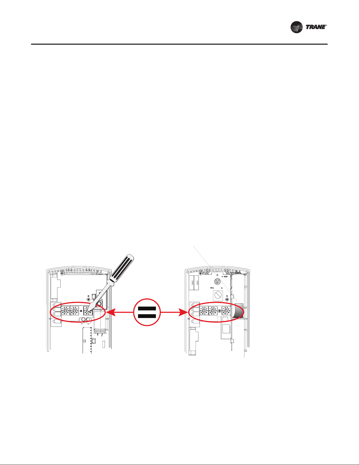
Replacing and Securing the Receiver Cover
1. To replace the receiver cover on the base plate, hook
the cover over the top of the base plate. Apply light
pressure to the bottom of the cover until it snaps in
place.
2. If necessary to keep thecover securely attached,install
the security screw into the bottom of the receiver
(
Figure 10, p. 22).
Figure 10. Snap receiver cover on base plate and attach
security screw
Security screw
Figure 11. LED5 stays on after applying power to the
receiver
LED5 stays constantly On
Receiver Indicates Readiness to Associate
After initial power up, thereceiver conducts a channelscan
for 10 seconds. During this time, the receiver selects from
16 available channels the clearest channel on which to
operate. LED1, LED2, and LED3 flash rapidly in succession
(round-robin style) while the channel scan is in progress.
Note: Do notattempt association until the channelscan is
finished. After the channel scan is finished, LED3
will begin blinking (one-blink pattern) to show that
the receiver is ready to be associated with a sensor.
LED3 will stop blinking when association has been
established (Figure 12, p. 22).
Applying Power to the Receiver
Restore power to the UCM. Observe LED5 on the receiver
(Figure 11, p. 22). It will light and stay constantly On when
24V power is normal.
22 VAV-SVX01D-EN
Figure 12. LED3 blinks when the receiver is ready to be
associated with a sensor
LED3
LED3 will begin
to blink after
10 seconds
Page 23

Wireless Zone Sensor
INSTALL
Powering the Sensor and Associating the Sensor to the Receiver
1. Verify the sensor is set to the same address as the
associated receiver.
2. Remove the insulation barrier, which is a plastic strip
located between the two batteries (
Figure 13, p. 23).
3. Association will automatically occur between the
sensor and the receiver. If the first association attempt
is unsuccessful, the sensor will automatically
reattempt association with the receiver every 10
minutes.
Note: A disassociated sensorwill transmit an association
request every 10 minutes. An associated sensor
that has lost communication with the receiver will
transmit an association request every 50 minutes.
Note: LED3 on the receiver stops blinking to indicate that
association has been established.
Figure 13. Removing the insulation barrier on the
sensor
SENSOR
2. View LED1, LED2, and LED3 to determine the strength
of the signal. View LED5 to determine the strength of
the battery.
Note: The LEDs will turn Off after 5 seconds to
conserve battery strength.
3. Record the results in your commissioning statement.
Figure 14. Testing signal and battery strength
SENSOR
Signal strength
LED1
LED2
LED3
LED5
B1 +
+
Pb
Pb-FREE
LED1
LED2
LED3
LED5
SIGNAL
LED5
BATTERY
STATUS
S1
ADDRESS
S3
S2
STATUS
S4
WIRELESS
I
J1
LED4
–
+
–
B2 -
S5
Testing Signal and Battery Strength
The following recommended test indicates signal and
battery strength. It verifies that the association process
was successful and that the batteries have adequate
charge. (For more information on LEDs, see
“Troubleshooting,” p. 45.)
1. Firmly press and release the Test button (S5) on the
bottom of the sensor (Figure 14, p. 23).
S5
(Test
button)
Push S5 firmly, then release
Disassociation
The receiver removes all stored association information,
conducts a channel scan, and restarts itself, if any of the
following are true:
• The receiver address is changed from its current
setting (001-999)
• The receiver receives a disassociation notification
from its associated sensor
• The receiver does not receive a communication from
its associated sensor within 35 minutes
VAV-SVX01D-EN 23
Page 24

UCM Programming and Operation
Chapter Overview
This chapter contains information about the following:
• Accessing Rover/Comm4
• UCM HomeTabs: At a Glance
• UCM HomeTabs: Instructions
• Entering and Exiting the Service Mode
• Overriding VAVs
• Resetting Diagnostics
Note: For Instructions onhow to use Rover Comm4, refer
Laptop Requirements and Complete Connection Instructions
For instructions on connecting a PC laptop to a Comm4
link, refer to the Installing Rover ServiceTool Version 5.0,
3270 3275.
Note: A hard copy of this document is in the Rover
Accessing Rover/Comm4
To connect to a Comm4 Link
Rover Overview
Rover is a service tool that allows parameters to be viewed
or adjusted in UCM v 2.0 and higher. Prior to UCM v 2.0,
you would need to use EveryWare to access units that
were stand alone.The operating and programming guide
for Rover is EMTX-SVX01*-EN.RoverComm4 is a software
application for monitoring, configuring, and testing VAV II/
III/IV controllers on Comm4 links. Rover Comm4 replaces
Every Ware service software.
Figure 15. Connecting to a Comm4 controller through a zone sensor.
1. Insert the Comm4 card in the PC laptop.
2. Connect the cables asshown in the appropriate figure.
See
controller through a zone sensor and Figure 16, p. 25
for Connecting to a Comm4 controller using alligator
clips.
Note: Make sure to maintain polarity.
to the Rover Comm4 online Help by clicking
Contents and Index on the Help menu.
package and an electronic copy (Installation.pdf)
can be found on the Rover installation CD-ROM.
Figure 15, p. 24 for connecting to a Comm4
Comm4
Adapter cable
RJ11
plug
24 VAV-SVX01D-EN
PCMCIA card
Page 25

UCM Programming and Operation
Figure 16. Connecting to a Comm4 controller using
alligator clips
Comm4
PCMCIA card
Red
Black
RJ11 plug
Adapter
cable
3. Double-click the Rover icon on the laptop PC desktop.
The Rover Service Tool screen will appear.
4. Double-click on the Comm4 Service Tool icon to
access a Comm4VAV UCM.This tool allows the user to
monitor, configure, and test Comm4.
Figure 17. Rover service tool
5. Rover/Comm4 will launch. Click to launchthe Scan for
Devices dialog box.
Figure 18. Rover/Comm4 application with the Scan for Devices dialog box.
VAV-SVX01D-EN 25
Page 26

UCM Programming and Operation
6. Theuser may search by the address of a singleUCM or
scan the range of UCM addresses specified
Note: Address for VAV UCM's range from 65-127.
7. Select the desired device or range of devices and click
the Scan button.You’ll be able to watch as the
applications scan for the selected data.
Note: The numbers selected for each device (65-127)
can be referenced back to address selection for
the UCM(s). See Table 6, p. 13, Dip Switch
settings.
Figure 19. Scanning for Devices screen
Figure 21. UCM home tabs
8. Once the scan is complete, the results will populate the
device tree on the left-hand side of the Rover/Comm4
screen.
Figure 20. Rover/Comm4 screen
9. Access the desired UCM from the device tree.
UCM Home Tabs: At a Glance
26 VAV-SVX01D-EN
Page 27

UCM Programming and Operation
StatusTab
Unit Info
UnitType:The different types of units for the selected
UCM.
Software Revision:The version of the UCM
software.
Setpoints
Active Heating: The active (or actual) heating
setpoint currently used by the UCM.
Active Cooling: The active (or actual) cooling
setpoint currently used by the UCM.
Zone Sensor: Shows the setpoint set at the zone
sensor for the controlled space.
Control
Mode: Shows whether the UCM is in occupied or
unoccupied mode.The control mode determines
which heating or cooling setpoints to use.
Action: Shows the UCM’s heating or cooling action.
The cool control action modulates the air valve as if the
supply duct air is colder than the space temperature.
The heat controlaction modulates the air valve as ifthe
supply duct air is warmer than the space temperature.
Binary Input
Type: For version 4.0 or higher UCMs, shows whether
the BIP is configured for occupancy or as a Generic BIP.
Status: Shows the position of the binary input Open/
Closed as a generic input or Occupied Unoccupied
from an occupancy input.
Fan
Type: The type of fan for the unit may be Series,
Parallel, or -- (none).
Status: Shows whether the fan is enabled or disabled.
Present Value: Shows whether the fan is on or off.
Auxiliary Input
Type: Shows the two types of auxillary inputs,
temperature and C0
one another.
Value: The displayed value will reflect either the
temperature (if it has a temperature sensor input) or
the PPM (if it is configured with a C0
Other
Position:The air valve or damper position.
Flow: This line displays the unit's airflow rate
expressed in the flow unitsselected in the setup menu.
This line will notbe shown if the UCMis usingposition
control instead of flow control.The UCM will use
position control if the flow sensor is failed or not
installed.The UCM will also use position control if the
.They are mutually exclusive to
2
input).
2
unit's airflow rate is less than 5% or greater than 110%
of the unit's cataloged CFM. For example, the UCM will
use position control for a size 600 CFM unit if the flow
is less than 30 CFM (5%) or greater than 660 CFM
(110%).
Note: Although the UCM will read flow down to
5% of cataloged and up to 110% of
cataloged, the range of MIN FLOW settings
is 0%, or 10% to 100% of cataloged. The
range of MAX FLOW settings is 100% of
cataloged. In the example above, the
lowest allowable MIN FLOW set point is 60
CFM (zero is also permissible) and 600 CFM
is the highest allowable MAX FLOW set
point.
ZoneTemp:The temperature, as reported by the zone
sensor.If the UCMis at version 4 orgreater and theunit
type is Bypass Damper Round or Rectangular, this field
is replaced by the supply air temperature. Dashes
appear if the zone sensor is not functioning when
allowed to be displayed.
Flow Control: The flow control override of the UCM.
Valid values: Auto, Open, Closed, Min, or Max.
Present Minimum: If the UCM is in pressure
independent mode (using flow control), the present
minimum, expressed in the appropriate flow units,
appears in the Present Minimum field. If the UCM is
in pressure dependant mode (using position control),
the minimum is expressed as percentage open.
Ventilation Ratio:The ventilation ratio equals the
outside air requirement divided by the air valve flow.
Type the occupied outside air requirement and the
unoccupied outside airrequirement onthe Setpoints
tab.
Max Hot water Override: Used to give status if Hot
water Valve is being overridden.
Heat
Type: This field shows the different types of reheat.
Choices are 1)None; 2) 3 Stage Electric;3) Electric Slow
Pulse Width Modulation; 4) Proportional Hot Water
with -Auxillary Heat; and 5) 3 Stage Hot Water.
Status: Shows whether the heat is enabled or
disabled.
Present Value: Shows whether the heat is on or off.
Setpoints Tab
The UCM Homescreens that areshown are non adjustable
and are used to show values only.
Note: The Setpoints tab will be defined in programming
the configuration menus.
VAV-SVX01D-EN 27
Page 28

UCM Programming and Operation
WirelessTab
Note: This tab displays the older style wireless not to be
confused with the new wireless that is being
currently offered.
When the UCM version is 3.0 or higher, this tab displays
the wireless sensorserial numberassignments. Up to five
wireless sensors may be assigned to a UCM. Four sensors
may be chosen as averaging, one sensor can be chosen as
backup.The backup sensors are optional. Backup sensors
for temperature and setpoint inputs only affect the UCM if
all averaging sensors fail. Backup button functions are
always used. Any combination of backup strategies is
valid.
For version 4.0 UCMs or higher, if the hardwired sensor is
configured as not present then the hardwired zone
temperature failure flag will not be set as long as at least
one wireless sensor is transmitting a valid zone
temperature. Likewise, if the hardwired sensor is
Figure 22. Select the configure button
configured as not present then the hardwired setpoint
sensor failure flag will not be set as long as at least one
wireless sensor is transmitting a valid setpoint.
Advanced ConfigurationTab
The UCM HomeTabs (and their screens) that are shown
are non adjustable and are used to show values only. The
advanced configuration tab will be defined in
programming the configuration menus
UCM Home Tabs: Instructions
Configuration
To access the data fields for each tab and to make
adjustments, select the Configure button as shown in
Figure 22, p. 28.To make adjustments, find the correct
parameter, change it, and download to UCM.
Setpoints Tab
Figure 23. Setpoints tab
28 VAV-SVX01D-EN
Page 29

UCM Programming and Operation
In Rover, the setpoints can be viewed at the UCM
Setpoints tab and then also changed by selecting the
Configure button. Following are descriptions of each line
on the UCM Setpoints tab.
Heating Setpoints
Active:The set point cannot be edited and reflects the
set point currently being used for Heatingtemperature
control.
Occupied: Set points have a range of 30.0°F- 100.0°F
(-1.1°C - 37.8°C). If a zone sensor thumbwheel set point
is not being used, this set point will be used as the
UCM's active heating set point during occupied times.
The cooling set point must be greater than or equal to
the heating set point plus 2.0°F (1.1°C).
Note: Occupied cooling and heating set points
must be set within the cooling set point
high limit and the heating set point low
limit in order to control to the proper set
points.
Unoccupied: Set points have a range of 30.0°F -
100.0°F (-1.1°C - 37.8°C).This heating set point is used
when the UCMis unoccupied.The unoccupied heating
set point must be less than or equal to the unoccupied
colling set point minus 2°F (1.1°C).The unoccupied
cooling set point must be greater than or equal to the
unoccupied heating set point plus 2.0°F (1.1°C).
Low Limit: This limit applies to the occupied mode
only starting in UCM version 4.1. Prior to version 4.1,
the limits would affect both the unoccupied and
occupied setpoints.The occupied heating set point is
subject to high and low limits.The cooling set point
high limit and the heatingset point low limit "cap"your
unoccupied set points, which directly impacts energy
savings.The upper level device is responsible for
preventing the resultingset points from being crossed.
This may happen if the heating set point low limit is
above the cooling set point high limit. Having the
cooling set point high limit and the heating set point
low limit set to the factory defaults (cooling high limit
= 102°F (38.8°C), heating low limit = 43°F (6.1°C))
should prevent them from impacting field operation.
High Limit:This limit applies to the occupied mode
only starting in UCM version 4.1. Prior to version 4.1,
the limits would affect both the unoccupied and
occupied setpoints. Both limits have a range of 30.0°F
- 100.0°F (-1.1°C - 37.8°C).The set point limits will be
applied to the active heating set point by the UCM but
will not restrict operator entry of set points.
Cooling Setpoints
Active:The set point cannot be edited and reflects the
set point currently being used for cooling temperature
control.
Occupied: Set points have a range of 30.0°F - 100.0°F
(-1.1°C - 37.8°C). If a zone sensor thumbwheel set point
is not being used, this set point will be used as the
UCM's active cooling set point during occupied times.
The cooling set point must be greater than or equal to
the heating set point plus 2.0°F (1.1°C).
Note: Occupied cooling and heating set points
must be set within the cooling set point
high limit and the heating set point low
limit in order to control to the proper set
points.
Unoccupied: Set points have a range of 30.0°F -
100.0°F (-1.1°C - 37.8°C).This cooling set point is used
when the UCM is unoccupied.The unoccupied cooling
set point must be greater than or equal to the
unoccupied heating set point plus 2.0°F (1.1°C).
Low Limit: This limit applies to the occupied mode
only starting in UCM version 4.1. Prior to version 4.1,
the limits would affect both the unoccupied and
occupied setpoints. Occupied Cooling set point is
subject to high and low limits.The cooling set point
high limit and the heatingset point low limit "cap"your
unoccupied set points, which directly impacts energy
savings.The upper level device is responsible for
preventing the resultingset points from being crossed.
This may happen if the heating set point low limit is
above the cooling set point high limit. Having the
cooling set point high limit and the heating set point
low limit set to the factory defaults (cooling high limit
= 102°F (38.8°C), heating low limit = 43°F (6.1°C))
should prevent them from impacting field operation.
High Limit:This limit applies to the occupied mode
only starting in UCM version 4.1. Prior to version 4.1,
the limits would affect both the unoccupied and
occupied setpoints. Both limits have a range of 30.0°F
- 100.0°F (-1.1°C - 37.8°C).The set point limits will be
applied to the active heating set point by the UCM but
will not restrict operator entry of set points.
Flow
Table 8. Valid flow ranges (by model)
VariTrane C 0, 10-150%
VariTrane D 0, 10-110%
VariTrane F 0, 10-100%
Minimum: Although the UCM will read flow down to
5% of cataloged,the range of MINFLOW settings is 0%,
or 10% to 100% of cataloged.The UCM will not drive its
flow below this minimum flow value under normal
operating conditions while in the cool mode. Cool
mode occurs when cool air is in the supply duct.The
entry in the Cooling Minimum field must be less than
or equal to the entry in the Maximum field.
Maximum: This range is 10% to 100% of the unit's
cataloged CFM size. Cooling and heating flow can be
edited to zero.The UCM will not drive its flow above
this maximum flow value under normal operating
conditions while in the Cool mode. Cool mode occurs
when cool air is in the supply duct.The entry for
VAV-SVX01D-EN 29
Page 30

UCM Programming and Operation
Maximum Flow must be greater than or equal to the
entry in any of the Minimum fields.
Min Heating: The UCM will not drive its position/flow
below this value under normal operating conditions
while in the HEAT mode (warm air in the supply duct)
or while it is using local heat.The Min Heating Flow
value must be less thanor equal to theMaximum Flow
value.
Min Local Heat: If the Min Local Heat flowis enabled,
then the Min Local Heat flow is used to determine the
minimum position/flow instead of the Min Heating
Flow when local heat is on.The entry for Min Heating
Flow must be less than or equal to the entry for the
Maximum Flow.
Outdoor Air Required
Occupied:The UCMs usethese values to calculate the
ventilation ratio. Valid range: 0 to 100%.
Unoccupied:The UCMs use these values to calculate
the ventilation ratio. Valid range: 0 to 100%.
Offsets
Heat Offset: This is the value subtracted from the
cooling thumbwheel setpoint to derive the heating
Figure 24. Setup tab
setpoint.This defines the minimum difference
between the cooling and heating setpoints. Valid
Range: 2°F to 10°F.
Control Offset: When control offset is active, the
UCM adds the value to the edited occupied cooling
setpoint and subtractsthe control offset valuefrom the
edited occupied heating setpoint to determine the
active setpoints.The control offset value does not
affect a zone sensor thumbwheel setpoint.
Fan Control Setpoint
The entry on this line determines when a parallel fan will
be turned ON and OFF. If "Parallel fan control" has been
edited to "DEG" the fan control offset will be entered as a
temperature offset (2° - 10°F) (1.1°C - 5.5°C) which will be
added to the heating set point. If "Parallel fan control" has
been edited to "FLOW"this line will be entered as a percent
(0 to 100%) if the unit is aVariTrane unit.The entry field on
this line willappear as "-"if the unitdoes not havea parallel
fan.
Important: This field is visible ONLY with Parallel Fan
Powered units.
SetupTab
The following are descriptions of each line on the Setup
tab.To make changes: Select the Configure button in
Rover and select the Setup tab. Make adjustments if
30 VAV-SVX01D-EN
necessary by opening a drop down arrow or changing a
value and press the download button.
Page 31

UCM Programming and Operation
Other Fields
Unit Type: Select the proper unit type.The unit type
information is maintained in the controller's EEPROM.
Important: Edit the unit type BEFORE editing any items
on the above list!
Unit types available for all versions:
• VariTrane C
• VariTrac - Round
• VariTrane D
• Generic
Unit types available for VAV version 4.0 and above:
• Bypass Damper - Round
• Bypass Damper - Rectangular
• VariTraneF-Round
• VariTraneF-Rectangular
• VariTrac - Rectangular
Editing the unit typealso affects the following entries:
• Heat type (The default is none)
• Fan type (The default is none)
• Unit size (The default is the smallest unit size)
• Air valve drive time
• Control Algorithm gains (KP, reset times, valve
flow constant) for air valve and water valve.
HeatType: The entry in the HeatType field identifies
what type of heat control algorithm the UCM should
use. If you edit the unit type, Rover automatically
changes the heat type to 0 (None). If you edit the heat
type or ifit changes automatically, Rover automatically
assigns the heat outputs per factory specifications.
Possible selections include the following:
• NONE - No heat available
• 1-3 stages electric
• Slow pulse width modulation - Electric (3 min.
time base).
• Prop hot water and aux. output
• 1-3 stages hot water/perimeter
Max Hot Water Override: When the Max Hot Water
Override check box is selected, the UCM turns on all
hot water outputs.This may be useful for water system
balancing.The Maximum Hot Water Override affects
only the following heat types:
• 3-Stage Hot Water - Rover energizes all three
heat outputs. If the unit has a fan, output 3 is not
affected.
• Hot Water with Auxiliary Output - Rover drives
open the hot water valve connected to outputs 1
and 2. If not controlling a fan, output 3 energizes.
Note: For the Max Hot Water Override to be
effective, the user MUST enable unit heat.
VAV-SVX01D-EN 31
The UCM will maintain the "Max hot water override"
condition over power failures.The only way to cancel
a Max HotWater Override is to clear the Max Hot Water
Override check box. If the unit does not have "1-3
stages hot water" or "proportional hot water and aux.
output will be grayed out and non selectable
Local Heat Setpoint: When the UCM version is 4.0
and the unit type is not "Bypass Damper - Rectangular"
or "Bypass Damper - Round", this value is used to
determine whether the Present Cooling Flow is
compared to the Min Local Heat Flow setpoint or to the
Min Heat Flow setpoint to determine when terminal
local heat is allowed.
Unit Size:The unit size is dependent on the unit type.
Select the unit size from a predetermined list.The unit
size for VariTrane C, VariTrane D, VariTrac, and VariTracRound type units are designated by their flow size
using the appropriate units (CFM, CMS, or L/S).The
unit size for VariTrane F-Round, VariTrane FRectangular, VariTrac-Rectangular, Bypass DamperRound, and BypassDamper-Rectangular type unitsare
designated by the dimensions (in inches) of their blade
dampers.
Flow Override:The entry in this field has the highest
priority of all flow overrides (group, binary inputs, or
upper level system functions). Override status can be
Auto, Open, Closed, Minimum, or Maximum.When a
non-auto flow override is edited from the UCM level,
the flow override will be maintained over power
failures. See Sequence of Operations for more
information.
Note: This is an excellent service point for
checking damper operation and CFM flow.
FanType: Select the type of fan used by the UCM. If
you edit the unit type field, Rover automatically
changes the entry to 0 (None). When the value of this
field is not None, the configuration of Output 3 is set to
Normally Open. Valid Selections: None, Parallel,
Series.
Note: The UCM may lockout the fan on its own if
any of the following apply: control action
HEAT; flow override to drive OPEN, CLOSE,
or MAX; or if the zone temperature sensor
does not have valid input.
Parallel Fan Control: This entry will determine if a
parallel fan will be controlled based on zone
temperature or on flow conditions. If "Parallel fan
control" has been edited to "DEG" the fan control offset
will be entered as a temperature offset (2° - 10°F) (1.1°
- 5.5°C) which will be added to the heating set point. If
"Parallel fan control" has been edited to "FLOW" this
line will be entered as a percent (0 to 100%) if the unit
is a VariTrane unit. The entry field on this line will
disappear if the unit does not have a parallel fan.
Note: See “Sequence of Operations,” p. 38
manual for details on parallel fan
operation.
of this
Page 32

UCM Programming and Operation
BIP Configuration: Version 4.0 or higher UCMs are
provided with a binary input that can be used to
monitor either an occupancy sensor or provide the
status of a generic binary input. Valid Selections:
Occupancy, Generic.
BIP Configuration default is Generic.The BIP
Configuration interface is for dry relay contacts
connected toTB4-1. In generic mode, the state of the
input is only passed on from the UCM to Summit. CPL
code must be written in order for Summit to utilize any
signal received from this generic input. When
configured as a generic input and communications are
active, an occupancy inputstate will bereflected by the
UCM to the upper level system controller.The upper
level system controller shall beresponsible for causing
any system changes necessary to provide occupied
control. When configured for generic mode, loss of
communications will result in the UCM defaulting back
into occupied mode. In occupancy detector mode, the
absence of a 24 VAC signal at TB4-1 indicates
occupancy and the presence of 24 VAC indicates nonoccupancy.When configured for an occupancy sensor
and communications are active, an occupancy input
state will be reflected by the UCM to an upper level
system controller.The upper level system controller
shall be responsible for causing any system changes
necessary to provide occupied control. When
configured for an occupancy sensor and
communications are not active and occupancy is
detected, the UCM shall transition to the occupied
mode of operation. Upon loss of the occupancy
indication from the occupancy detector, theVAV UCM
will revert back to unoccupied mode. However, when
configured for an occupancy sensor and
communications are active, loss of communications
does not result in the VAV UCM defaulting to occupied
mode.
Cooling Flow
Present Value:This present value shows the current
flow being reported by the UCM.
Measured Value: If the present value of flow is
incorrect the operator can enter the Measured value
and Cooling Flow Correction factor will automatically
be recalculated.
Note: This can be used to have the correct
present value at the UCM as compared to
the actual CFM at the inlet of the unit
Correction Factor: Value displayed to show how
much the flow input needed to be corrected.
Auxiliary Input
Type: When the UCM version is 4.0 or higher the
analog input labelled A/C0
either an auxiliary temperature sensor or a C0
Aux Input Select defaults toAuxTmp SensorThis entry
determines the configuration of the A/C0
terminalTB3-5 of the UCM. Selecting AUXTMP
can be used to monitor
2
input on
2
sensor.
2
SENSOR configures the input to use an auxiliary
temperature sensor. Selecting C0
the input to use a C0
exclusive.
Value: When the UCM version is less than 4.0 or when
the UCM version is 4.0 higher and the Auxiliary Input
Type is set toTemp Sensor, the current auxiliary
temperature is displayed in this field.The value is
reported after applying the calibration offset by the
UCM. If the temperature sensor fails, dashes (---)
display instead of the temperature.
Calibration:The auxiliary temperature calibration
offset adds the offset to the value read by the auxiliary
temperature sensor.
EXAMPLE: If the auxiliary temperature sensor
indicates a temperature of 74.0°F (23.3°C) and the
auxiliary temperature calibration offset is -1.5°F, the
actual temperature used by Rover is 72.5°F (22.5°C).
Valid range: -10.0°F - 10.0°F (-5.5°C - 5.5°C).
Note: It may take 30 seconds (after a new offset is
entered) before the calibration is factored
into the auxiliary temperature.
sensor.They are mutually
2
Sensor configures
2
Outputs
1-3: The outputs can be either Normally Open or
Normally Closed. Outputs 1 and 2 can be edited only
when the heat type is 3-Stage Hot Water. In all other
cases they are set to Normally Open. If there is a fan,
output 3 is set to Normally Open and cannot be edited.
If there is no fan, output 3 can be edited if the heat type
is either 3-Stage Hot Water or HotWater with Auxiliary
Output.
Wired Zone Temperature
Value: This field displays the value of the wired zone
temperature sensor after the UCMhas added thewired
zone temperature calibration offset. If the zone sensor
has failed or is not present, dashes (---) appear.
Calibration:The zone temperature sensor calibration
offset.The UCM adds the offset to the value read by the
zone sensor. After you add a new offset, Rover may
take up to 30 seconds to update the displayed
temperature. Valid Range: -10°F - 10°F (-5.5°C - 5.5°C).
Wired Sensor
Use: This input determines the function of the wired
zone temperature sensor. Select Averaged to use the
sensor as part of a wired system OR to use the sensor
as an averaging sensor in an older style wireless
system.
Type: This line is used to edit the type of temperature
sensor being used.The sensor type can be selected as
eitherThermistor or RTD.
Note: Factory supplied sensors are thermistors.
32 VAV-SVX01D-EN
Page 33

UCM Programming and Operation
Note: Set point vote determines the weighting of the set
point vote.The range is 0-9.This number
represents the number of votes the sensor gets
when the set points are averaged. If "0" is selected
the sensor gets no vote.
WiredThumbwheel
Select the check box to enable the local thumbwheel
setpoint input. If theThumbwheel Setpoint check box is
not selected, the UCM does not respond to the following
thumbwheel functions:
• Setpoint
• Ability to generate a "drive to max" command
• Ability to generate a "go unoccupied" command
Note: Disabling thumbwheel functions does not
disable the On/Cancel push button feature.
Figure 25. Wireless tab
Setpoint: This line displays the value of the
thumbwheel setpoint after the calibration offset is
applied. If theThumbwheel is placed in the ** position
and the ON button is pressed, the UCM will request to
go unoccupied. If theThumbwheel is placed in the *
position and the ON button is pressed, the UCM will
request a maximum override.Valid Range: 50°F - 85°F
(10°C - 29.4°C) Fail, Max, Unocc.)
Calibration: The value of the zone temperature
sensor calibration offset.The UCM adds the offset to
the value read by the zone sensor.After you add a new
offset, Rover may take up to 30 seconds to update the
displayed temperature. ValidRange: -10°F - 10°F (-5.5°C
- 5.5°C).
WirelessTab
This tab was used for the old style wireless system that
used spread spectrum technology. For details on how this
can be set up forexisting applications using the older style
wireless sensor see VAV-SVX01B-EN (VAV UCM 4.0).
VAV-SVX01D-EN 33
Page 34

UCM Programming and Operation
Advanced ConfigurationTab
Figure 26. Advanced configuration tab
Air Valve/Damper
Drive time:This adjustment can be used to match the
DDC UCM 4.2 to the actuator drive time.The air valve
damper actuator drive time will be automatically
adjusted to the type ofTrane Unit type selected.
Min DriveTime: Displays the minimum time that the
output can be driven.This value restricts the change in
the mechanical output. Until the desired change in
position will take at least the minimum drive time, the
output will not be changed.
Air Flow
KP: This is an internal factor used by the PID control
loop that modulates the air valve or damper.The value
is predetermined by unit type and unit size.
ResetTime: This is an internal factor used by the PID
control loop that modulates the air valve or damper.
The value is predetermined by unit type and unit size.
PWM Heat
KP:This is an internal factor used by the PID control
loop that modulates the terminal heating.The value is
predetermined by unit type and unit size.
ResetTime: This is an internal factor used by the PID
control loop that modulates the terminal heating.The
value is predetermined by unit type and unit size.
Other
UCM 2/3 Trane Box: Shows whether the UCM is
configured as aTrane box. By default only a box
configured as generic is not aTrane box.
Cmd Unit I / Comfort Manager: Select the check box
to use theVariTrane D best fit configuration. Clear the
check box to use the Genericbest fit configuration.This
check box applies to UCM versions 4.0 and higher.
When aVariTrane F style UCM orVariTrac -Rectangular
UCM is programmed, it is also configured to its best fit
to a generic style or VariTrane D style box. Using this
method, newer boxes can be used as replacements or
to expand legacy systems.
Note: The Command Unit I and Comfort
Managers do not recognize a generic unit
type.
Valve Gain: This is an internal factor used by the PID
control loop that modulates the air valve or damper.
The value is predetermined by unit type and unit size.
Water Valve DriveTime: The drive time, in seconds,
to stroke the water valve from 0 to 100%.
Valve Flow Constant:This is an internal factor used
by the PID control loop that modulates the air valve or
damper.The value is predetermined by unit type and
unit size.
IAQ Multiplier: This value is usually sent by the ICS
system to adjust the minimum flowsetpoint.When the
value is greater than 1.0, the VariTrac energy saver
feature to ignore minimum flow is ignored and the
minimum flow is enforced at the unit controller.
VariTrane F PD Min Position:The minimum damper
position for aVariTrane F style box when it is operating
in the pressure dependant mode. Valid range: 0 to
100%.
34 VAV-SVX01D-EN
Page 35

UCM Programming and Operation
Entering and Exiting the Service Mode
Controllers must be online and in the service mode to
receive an override.The service mode disables control
fromTracer and places Rover/Comm4 in command of the
controller. Controllers that are in the service mode appear
in bold in the device tree on the left side of your screen.
More than one controller can be in the service mode at one
time.
You can place a controller inthe service mode manuallyor
let Rover/Comm4 do so automatically when you start an
override. Controllers exit the service mode automatically
15 minutes after the last override or when you manually
release them.
To enter the service mode:
1. Connect to the Comm4 link and scan for devices. See
‘Accessing Rover/Comm4’ p. 24
2. In the device list on the left side of your screen, doubleclick the controller that you want toplace in the service
mode.
3. Click the Enter Service Mode button. While the
controller is in the service mode, it appears in bold in
the device list.
To exit the service mode, do one of the following:
• Wait for 15 minutes (Rover Comm4 does notneed to be
online with the controller).
• For each controller in the service mode, click the Exit
Service Mode button.
1. In the device list on the left side of your screen, doubleclick the controller for which you want to reset
diagnostics.
2. Click the Diagnostics button.
3. Click the Reset button. Rover Comm4 attempts to clear
all diagnostics on the controller and a message
appears.
4. Click OK to close the message and the Diagnostics
dialog box.You can click the Diagnostics button
again to verify which diagnostics have been cleared.
Saving VAV Program
Each VAV unit with a UCM 4.2 has been factory
commissioned with a program that can be saved to your
hard drive.
This can be usedto save theoriginal programfor a backup
in case unit needs to be put back to original specifications
or to download into a UCM 4.2 DDC controller that has like
parameters that has been corrupted.
1. Select the Configure button, and the Configuration
screen will appear.
OverridingVAVs
When you override a controller, Rover Comm4
automatically places the controller in the service mode.
The controller is automatically released from the service
mode after 15 minutes or when you click the Exit Service
Mode button for the device.You can manually release
overrides by selecting the appropriate release command
in the Override dialog box.
1. On theTools menu, click Overrides.
2. Select whether to overrideTUCs or VAVs.
3. Click the units you want to override.
4. In the list of overrides, click the type of override you
want to perform.
5. Click the Override button. The controller
automatically enters the service mode and exits the
service mode 15 minutes after receiving an override.
Resetting Diagnostics
You can reset diagnostics only forTUCs (not VAV units).
VAV-SVX01D-EN 35
Page 36

UCM Programming and Operation
Figure 27. Configuration screen (save as)
2. Click the File menu and click Save As. 3. The Save As dialog box will appear. Name unit and
click Save.
Figure 28. Save As prompt
Downloading Program Files from PC to DDC UCM 4.2
1. Select the Configure button, and the Configuration
screen will appear
36 VAV-SVX01D-EN
Page 37

Figure 29. Configuration screen (open)
UCM Programming and Operation
2. Click the File menu and click Open.
3. The Open dialog box will appear. Select the file you
wish to open and click the Open button.
Figure 30. Open dialogue box
4. Download to DDC VAV controller.
5. Program is now in controller.
VAV-SVX01D-EN 37
Page 38

Sequence of Operations
Chapter Overview
This chapter contains information about the following:
• Single Duct Units
• Override Conditions (Single Duct)
• Fan-Powered Units
• Parallel Fan-Powered Units
• Override Conditions (Parallel Fans)
• Series Fan-Powered Units
• Override Conditions (Series Fan)
• Zone Sensor Functions
• Flow Sensor
• Failure Modes
Single Duct Units
When the UCM control action is COOL, the UCM controls
the modulation of the air valve as a cooling source to
maintain the “active cooling set point”. Airflow is varied
between the minimum and maximum flow set points to
maintain temperature set points. A PI control algorithm is
utilized to minimize the measured difference between the
active zone set point and the actual zone temperature.
It is possible for unitsto utilize electricor hot water heating
coils to maintain temperature set points. After the
temperature loop calls for minimum cooling flow and the
zone temperature is at or below the heating set point,
these units shall control to their respective “Minimum
Heating Flow”. Once this “Minimum Heating Flow” is
established, heat is allowed to operate according to the
“Heat ControlType” specified for the controller. For
electric heat units, this heating minimum flow set point
must be at or above 20% of the unit cataloged airflow.
Electric heat may be pulse width modulation or staged
electric heat. Staging has the following ON and OFF switch
points. UCM 3.3 and later allow hot water to turn on
regardless of flow/position
Table 9. Set points
Stage ON Switch point Off Switch point
1 At the heating set point
1°F below the heating
2
3
set point
2°F below the heating
set point
0.5°F above the heating set
point
0.5°F below the heating set
point
1.5°F below the heating set
point
Override Conditions (Single Duct)
The UCM occupied controls can be overridden by the
following override commands:
Unoccupied
If the control mode is unoccupied (either as edited by
software or as determined by the binary input), the
unoccupied cooling and heating temperature set points
are used for temperature control. Heat outputs remain
active.
Heating
If the controlaction is edited to HEAT, the UCM controls the
air valve as a heating source rather than cooling. Electric
reheat is available the supply air temperature (or auxiliary
temperature) is below 70ºF. Local hot water reheat is
always available to keep the zone above the heating set
point.The “Heating Minimum Flow Set Point” will set the
minimum flow.
Flow Control Override
Flow control may be overridden by any of the following
commands:
• Drive Air Valve Fully Open.The air valve will be fully
open and heat outputs disabled.
• Drive Air Valve Fully Closed.The airvalve is driven fully
closed and heat outputs disabled.
• Drive Air Valve to Minimum Flow.The air valve is
driven to the minimum airflow set point.The heat
outputs remain operational.
• Drive Air Valve to Maximum Flow.The air valve is
driven to the maximum airflow set point.The heat
outputs remain operational.
Heat Control Override
Heat control can be disabled, locking out heat outputs.
Control Offset
Control offset may be enabled, which adjusts the edited
cooling and heating set points.
Recalibrate (Reset)
The recalibrate function can be enabled. If enabled, the
unit will perform a recalibration.
Hot water heat control may be either ON/OFF or
proportional. ON/OFF hot water is activated on the same
schedule as staged of electric heat.
Utilization of the “Heating Minimum Flow” set point
allows separate minimumflows to beactive depending on
whether or not the unit heat is active.
38 VAV-SVX01D-EN
Page 39

Sequence of Operations
Fan-Powered Units
Table 10. Fan actuation schedule
FAN TYPE OCCUPIED UNOCCUPIED
Series ON
Cool mode: ON if
zone temp
Parallel
based on
Temperature
Parallel
based on Flow
<heating set
point + fan offset
fan offset +
0.5°F
Heat mode: fan
off unless reheat
is on
Cool mode: ON if
flow < fan set
point OR if flow <
active minimum
flow set point
Heat mode: fan
off unless reheat
is on
Cool mode: OFF
if zone
temp > heating
set point + Heat
mode: fan off
unless reheat is
on
Cool mode: OFF
if flow >
fan set point +
5% AND
flow > active
minimum
flow set point
Heat mode: fan
off unless reheat
is on
OFF
if valve closed
AND reheat off
OFF unless local
reheat is on
OFF unless local
reheat is on
Parallel Fan-Powered Units
Occupied Units
Air valve control for parallel fan-powered units is the same
as for single duct units.
The first heat output is utilized to control the fan.The
remaining outputs are utilized to control heat. Fan
energization is a function of the “Parallel Fan Control
Offset”. The parallel fan control can be specified as an
offset temperature in degrees above the heating set point
or as a flow offset in CFM.The fan will be energized above
the fan control offset if reheat is required.
Parallel Fan Flow Type Control
If the fan control is based on flow, the unit fan will be
energized whenever primary airflow is below this set
point. For this parallel fan configuration, the fan control
point, if specified in a percentage of unit airflow, must be
set between 15% and 30% of the units cataloged airflow to
assure proper operation. A differential of 5% exists to
avoid excessive fan cycling.
Note: The fan control offset is entered in CFM when used
on a VariTrane unit.
Table 11. Heat stages
Stage point ON Switch point OFF Switch
1 At the heating set point
2
1°F below the heat set
point
0.5°F above the heat set
point
0.5°F below the heat set
point
Whenever the fan is energized, the primary airflow is
controlled at the “Heating Minimum Flow” set point.
Override Conditions (Parallel Fans)
The UCM occupied controls can be overridden by the
following override commands:
Unoccupied
If the control modeis unoccupied,the unoccupied cooling
and heating temperature set points are used for
temperature control. Fan and heat outputs are activated at
the unoccupied heating set point.
Heating
If the control action is HEAT, the UCM controls theair valve
as a heating source rather than cooling. Fan and heat
outputs are disabled for parallel units with electric heat. If
the heat type is hot water heat, then the fan will remain on
if the heat is on during the heating control action.
Flow Control Override
Flow control may be overridden by any of the following
commands:
• Drive AirValve Fully Open.The air valve will be driven
fully open. Fan and heat outputs are disabled.
• Drive Air Valve Fully Closed.The airvalve is driven fully
closed. Fan and heat outputs are disabled.
• Drive Air Valve to Minimum Flow.The air valve is
driven to the minimum airflow set point.The fan and
heat outputs remain operational.
• Drive Air Valve to Maximum Flow.The air valve is
driven to the maximum airflow set point.The fan and
electric heat outputs are disabled (hot water heat
remains enabled).
Heat Control Override
Heat control can be disabled, locking out heat outputs.
Parallel Fan Temperature Type Control
When the fan control offset is in terms of a temperature
above the heating set point, the fan shall be energized
whenever the zone temperature is below the heating set
point plus the fan control offset. A differential of 0.5°F
(0.3°C) shall apply to this switch over to avoid fan cycling.
Heat stages are energized on the following schedule:
VAV-SVX01D-EN 39
Fan Control Override
Fan control can be disabled, locking out both fan and heat
outputs.This affects only parallel fan-powered units.
Control Offset
Control Offset may be enabled, which adjusts the edited
cooling and heating set points.
Page 40

Sequence of Operations
Recalibrate (Reset)
The recalibrate function can be enabled.
Series Fan-Powered Units
Occupied Units
Air valve control for series fan-powered units is the same
as both single ductand parallel fan-powered units. During
the occupied mode of operation, the series fan is
continuously energized. Heat stages are energized on the
following schedule:
Table 12. Heat stages
Stage ON Switch point OFF Switch point
1 At the heating set point
2 1°F below the heat set point
0.5°F above the heating set
point
0.5°F below the heat set
point
Override Conditions (Series Fan)
The UCM occupied controls can be overridden by the
following override commands:
Unoccupied
If the control mode is edited to unoccupied, the
unoccupied cooling and heating temperature set points
are used for temperature control.The series fan and heat
outputs will be activated as necessary to maintain the
current unoccupied set points.The fan control point is not
utilized on series units. On electric heating and hot water
heating units, the fan and heat are energized at the
unoccupied heating set point.The minimum cooling flow
set point is reset to zero unless minimums are being
enforced by a group override. A series fan will be
energized anytime the air valve’s position is greater than
0%.
Heating
If the controlaction is edited to HEAT, the UCM controls the
air valve as a heating source rather than cooling.The unit
fan remains operational. Unit heat on an electric heat unit
is locked out, but remains active on hot water units.
Flow Control Override
Flow control may be overridden by any of the following
commands:
• Drive AirValve Fully Open.The air valve will be driven
fully open. Fan operation is unaffected, but heat
outputs are locked out.
• Drive Air Valve Fully Closed.The airvalve is driven fully
closed.The fan and heat outputs are locked out.
• Drive Air Valve to Minimum Flow.The air valve is
driven to the minimum airflow set point.The fan and
heat outputs remain operational.
• Drive Air Valve to Maximum Flow.The air valve is
driven to maximum airflow set point.The fan and heat
outputs remain operational.
Heat Control Override
Heat control can be disabled locking out heat outputs.
Fan Control Override
Fan control overridedoes not affect fan operation on series
fan-powered units.
Control Offset
Control offset may be enabled which adjusts the edited
cooling and heating set points.
Recalibrate (Reset)
The recalibrate function can be enabled.
Zone Sensor Functions
The zone sensor utilizes a thermistor element to measure
zone temperature.The zone sensor has the following
options:
Zone Temperature
Each zone sensor module includes a zone temperature
sensor.
Set Point
A UCM willonly use thezone sensor thumbwheel set point
(during occupied time) if “Zone sensor thumbwheel
functions” is edited to ENABLE on the UCM setup screen.
ON Timed Override (TOV) and CANCELTimed
Override (TOV)
The ON (TOV) and CANCEL (TOV) commands can be
issued by pressing the ON or CANCEL buttons on any of
the UCM zone sensor modules.
• When an ON button on a zone sensor is pressed
(shorting the zone temperature sensor circuit), the
UCM will set aTOV signal, clear theTOV cancel signal
if it is set, and start the two hour timed override timer.
TheTOV signal will be maintained for two minutes.
• When a CANCEL button on a zone sensor module is
pressed for at least two seconds, the UCM must set a
TOV cancel signal, clear theTOV signal if it is set, and
set the timed override timer to zero.
• Pressing any zone sensor module’s ON or CANCEL
button will not affect the zone temperature reported
from the UCM.
Note: TOV push buttons should be pressed for at least 2
seconds and not more than 15 seconds.
Drive to Max and Go Unoccupied
When a zone sensor thumbwheel is turned to its high-end
limit, indicated by a “*” on the thumbwheel, and the ON
button is pressed, the UCM will initiate a “Drive to Max”
40 VAV-SVX01D-EN
Page 41

Sequence of Operations
command. When a zone sensor thumbwheel is turned to
its low limit, indicated by a “**” on the thumbwheel, and
the ON button is pressed, the UCM will initiate a “Go
UNOCCUPIED” command.The UCM will maintain the
command until the zone sensor set point is adjusted to
within the rangeof 50° to85°.Any zone sensor module that
has a thumbwheel and ON (TOV) button can initiate these
commands.
Notes:
• The UCM will not send these commands if “Zone
sensor thumbwheel functions” is edited to DISABLE
on the UCM setup screen.
• When an ICS is connected to the UCM, the UCM will
pass the commands to the ICS without taking any
control action of its own. Since this is true, it may take
a minute or so after the command is initiated before the
UCM actually goes unoccupied or is driven to
maximum.
• The UCM will not generate aTOV signal when a Drive
Max or Unoccupied command is initiated.
• Pressing the ON button will not affect the zone
temperature reported from the UCM.
• The UCM will remain in the Drive Max or Unoccupied
status over power failures IF“*” or“**” (respectively)
have been initiated prior to the power failure.
Note: TOV push buttons should be pressed for at least 2
seconds and not more than 15 seconds.
Flow Sensor
The flow control is pressure independent utilizing the
VariTrane flow-sensing ring.The flow ring provides one of
the most accurate differential pressure flow
measurements in the industry by averaging pressure
differentials across 16 sensing points.These sensing
points, arranged in a ringconfiguration tocompensate for
various inlet duct configurations, providea signal accurate
to within +/-5% of cataloged CFM provided there is 1½inlet diameters of straight ductwork upstream of the VAV
box.The pressure differential signal from the flow ring is
then converted to an electrical signal, which is utilized in
the control algorithm of the unit controller. It is
recommended that the recalibrate sequence be initiated
on a weeklybasis. Assuming 1½ inlet diameters of straight
duct work and proper system recalibration, total system
flow measurement accuracy (flow ring, transducer, and
UCM controller) during the occupied mode should be +/5% of cataloged airflow over the typical operating range of
20% to 100% of unit cataloged airflow.
to maintain zone comfort during a failure.The failure
conditions and backup operating sequences are explained
below.
Temperature Sensor Failure
Failure of a zone temperature sensor (open or below low
limit of 0°F (-17.8°C) will cause fan and heat outputs to be
disabled and airflow to be controlled to the minimum
cooling flow set point. If the measured temperature fails
above the high limit (short or above 100°F (37.8°C), the
airflow shall be controlled to the maximum flow set point.
Flow Sensor Failure. If a flow sensor failure is reported
(open, short, fails calibration, or is out of the normal range
of 5% to 110%of box cataloged),the UCM will immediately
revert to a position-based, pressure dependent control
algorithm.This allows full operation of the unit and
maintains the ability to control the zone temperature. If a
flow sensor has failed, it is periodically checked for proper
operation. If found to be operating properly, the UCM will
be switched to thestandard pressure independent control.
Otherwise, position control is used as long as the flow
signal remains out of range.
Local Thermostat Set Point Failure
Failure of a local thermostat set point adjustment
potentiometer will cause the UCM to revert to the edited
occupied cooling and heating set point.
Communications Failure
A fifteen-minute failure in communications between the
UCM andTracer Summit will cause the UCM to:
• Operate in the occupied mode (provided that no
occupancy sensor is present on inputTB4-1).
• Set the IAQ multiplier to 1.0.
• Disable the control offset.
• Use the control action as determined by the auxiliary
sensor.The auxiliary temperatureis compared to the zone
temperature. If the supply air temperature is 10ºF (5.5°C)
greater than the zone temperature, then the control action
will be heat. If the supply air temperature is less than or
equal to the zone temperature, the control action will be
cool. If the supply air temperature is between the zone
temperature and thezone temperature +10ºF (5.5°C)(zone
temperature < supply air temperature < zone temperature
+ 10ºF) (5.5°C), the control action remains the same and
the UCM controls to the minimum flow set point. If an
auxiliary sensor is not installed and the VAV unit is not
underTracer Summit control, the UCM will retain the last
control action in effect.
Failure Modes
Each UCM has diagnostic capabilities, which allow it to
sense various failure conditions.This diagnostic capability
aids in maintenance and trouble shooting of the system.
Along with reporting these failure conditions, the UCM will
follow a pre-programmed operating sequence designed
VAV-SVX01D-EN 41
Page 42

Air and Water Balancing
Chapter Overview
This chapter contains information about the following:
• Air Balancing
• Water Balancing
Air Balancing
After the unit has been mounted and all electrical and duct
connections have been made, the air distribution system
should be balanced.The proper variable air volume
balancing procedures depend on the type of VAV system
used and the options specified on theVariTrane® unit.This
section will cover the basic balancing procedures and
calibrations needed to balance an air distribution system
using VariTrane units. This section suggests only one
balancing procedure. Since there are many possible air
balancing procedures, keep in mind that these procedures
are only suggestions.
Note: Before performing these balancing procedures, the
calibration command should be initiated at least 15
minutes prior to the balancing procedure.
System Checkout
• Check the VAV system installation for conformity to
design.
• Walk the entire system fromair handling equipment to
the terminal unit to determine variations of installation
from the plans.
• Check for inadvertent obstructions in the ductwork
(such as closed fire dampers).
• Insure that any turning vanes, filters, and dampers
(both volume and fire) are installed in the correct
position.
• There should be a1.5 duct diameterlong run ofstraight
ducting into the VAV units inlet.
System Setup
• Set the outside air dampers to their minimum position.
• Start the supply and return air fan(s).
• Before balancing the system, ensure that there is
enough CFM for all zones.
6. Drive all VAV boxes MAX.
• Starting with each individual branch duct, open all
the VAV units in that branch duct to the maximum
cooling position.
Note: This can be done using Rover or EveryWare by
giving each UCM a "Drive Max " command or by
rotating the Zone sensor set point knob to the " * "
position, and hold theTOV ON button for two
seconds.The damper will remain at its maximum
set point until the zone sensor knob is moved back
into the normal operating range.
7. Read airflowat themost remote unit. In mostsystems,
this will be theVAV unit located furthest from the fan.
This will be the unit in the system that will be critical
from an airdelivery set point. Ifairflow is not adequate,
increase the supply fan CFM to achieve adequate
airflow.
• If the CFM is at or above design, the system can now be
balanced. If the measured CFM is below design,insure
the VariTrane unit is in full cooling position.
• If the air delivery through this VariTrane unit is still
below the design requirements, increase the supply
fan CFM to achieve adequate airflow.
Note: To increase supply fan CFM check to make sure
VFD/IGV are giving max output. If not at max
output; adjust discharge static setpoint until at max
output. If already at max output then make the
required adjustments to pulley sizes, motor sizes
and electrical connections to accommodate fan
speed changes. If any adjustment havebeen made,
repeat step 2.
• If after adjusting the fan to its maximum capacity there
is still a shortage of airflow, shut off part of the system
to provide enough airflow to balance the other part of
the system.This can be done using Rover or the
"Override to Unoccupied" command ("**") at the zone
sensor.
8. After determining that there is enough CFM for all
zones, drive all the VAV boxes to MIN.
Note: If the VAV boxes have already been assigned to
groups and these groups are separate thermal
zones, then the balancing can be done on a group
basis.
VAV Single Duct Unit Air Balancing
Select a group to balance and give the VAV units a
recalibrate command and then the group a flow override
Drive MAX command.
Note: If the VAV boxes have not been placed in a group,
each individual UCM can be overridden to Drive
MAX in the Override menu in Rover. However, this
will be more time consuming.
42 VAV-SVX01D-EN
Page 43

Figure 31. Measured value field
Air andWater Balancing
If reported flow in Rover is different from the measured
CFM (flow hood measurement) a cooling flow correction
Figure 32. UCM set point menu
can be calculated by Rover by entering the measured flow
in the measured value field. See above, Figure 31, p. 43.
VAV-SVX01D-EN 43
Page 44

Air andWater Balancing
1. Adjust eachVAV box maximum flow set point required
for its zone using the UCM set points menu. See
Figure 32, p. 43.
Note: This could already be done in the factory in its
commissioning process.
2. After balancing a group/box, return that group/box
flow override to AUTO.
Figure 33. Rover configuration UCM setup menu
3. Continue to the next group/box repeatingVAV unit air
balancing procedures until each unit is delivering the
correct CFM.
4. Upon completion of the VAV air balancing, remove all
overrides.
5. Initiate a recalibrate command.
Water Balancing
EachVAV UCM can have its hot water valve overridden to
drive fullyOPEN (2-positionand proportional).This can be
done in the Rover Configuration UCM setup menuand can
be used to assist in water balancing.
1. Access VAV UCM with Rover service software.
2. Select a VAV box to balance, and drive its hot water
valve open (max hot water override).
3. Using hydraulic pressure gauges, measure the flow
across the high and low ports. Convert this data from
a pressure differential to gallons per minute (GPM).
4. Adjust the circuit setter until it is within design
specifications.
5. Once achieved, lock the circuit setter in place. Mark the
position with a permanent indicator.
6. Remove all gauges and software overrides.
44 VAV-SVX01D-EN
Page 45

Troubleshooting
WARNING
Live Electrical Components!
During installation, testing, servicing and
troubleshooting of this product, it may be necessary to
work with live electrical components. Have a qualified
licensed electrician or other individual who has been
properly trained in handling live electrical components
perform these tasks. Failure to follow all electrical
safety precautions when exposed to live electrical
components could result in death or serious injury.
Chapter Overview
This chapter contains information about the following:
• SP: Diagnosing the Problem
• Diagnostic Log
Diagnostic Log
The Diagnostic Log reports diagnostic and informational
modes/items that are not in the unit’s normal operation.
Figure 34. Diagnostic log
• Diagnostic Table
• Troubleshooting Procedures
• UCM Failure Procedures
• UCM Communication Loss Procedures
• Wired Zone Sensor Failure Procedures
• Wired Zone Setpoint Failure Procedures
• Wireless Zone Sensor Failure Procedures
• Airflow Failure Procedures
• AuxiliaryTemperature Sensor Failure Procedures
• Auxiliary C0
• VAV Damper Failure Procedures
• VAV Series Fan Failure Procedures
• VAV Parallel Fan Failure Procedures
• Trane/Honeywell Proportional Valve Check Out
Procedures
Sensor Failure Procedures
2
Some of the items reported (see Figure 35, p. 46) are listed
to aid in understanding current operation. Reported items
are: 1)Timed Override Exists, 2) CancelTimed Override, 3)
AuxiliaryTemperature Sensor Not Present, 4) Unoccupied
Request from Zone Sensor ** Function, 5) Max Flow
Request from Zone Sensor * Function, 6) Calibration in
Progress, and 7) Pressure Dependent Operation.
VAV-SVX01D-EN 45
Page 46

Troubleshooting
Figure 35. Items reported
Diagnostic Table
Use the DiagnosticTable (Table 13, p. 46) for failure
parameters and Comm. 4 UCM actions to helpunderstand
issue.
Table 13. Failure parameters and Comm. 4 UCM actions
Sensed
Parameter Failure Criteria Action Taken
If failed open, control
valve as if very cold
temperature. If failed
shorted, control as if
very hot temperature.
Setpoints from EEPROM
used.
If unsuccessful at
recovering flow signal,
operate in pressure
dependent mode until
flow signal regained.
For UCM 4, if flow input
is open or shorted the
flow failure flag will be
set and pressure
dependent mode will be
used.
UCM 3.3 is the only
version that sets the
failure flag if the valve is
flowing too much air
(>110% or 150% for
series C)
Zone Temperature
Thumbwheel
Setpoint
Air Flow
Open OR Short (> 25
seconds) AND no active
wireless sensors.
Open OR short AND no
active wireless sensors.
For UCM 3.3 and prior,
Flow < 10% when flow
control point > 10% OR
flow > 110% or 150%
for series C.
For UCM 4, Flow < 5%
when flow control point
> 10% OR flow > 115%
or 155% for series C.
UCM 4 will also indicate
open/short for the air
flow sensor.
Table 13. Failure parameters and Comm. 4 UCM actions
Sensed
Parameter Failure Criteria Action Taken
Auxiliary
Temperature
(a)
CO
Supply Air
Temperature
(VariTrac Bypass
Damper mode)
Supply Air
Pressure(a)
(VariTrac Bypass
Damper mode)
(a) UCM 4.0 and above will not detect an open. Instead, it will report 258
ppm.
(b) New to UCM 4.2
(b)
Open or short
Short or C02 value
< 200 ppm
Open or short
Open or short
Tracer supplied data
used for auto
changeover logic.
For UCM 4 with the aux
input configured for C0
mode: if the C02 input is
shorted or reading
below 200 ppm, the
Failed C0
SAT input is shorted or
sensor failure flag will
SAP input is shorted or
sensor failure flag will be
sensor failure
2
flag will be set.
For UCM 4 in bypass
damper mode: if the
open, the Failed SAT
be set.
For UCM 4 in bypass
damper mode: if the
open, the Failed SAP
set.
UCM Failure Procedures
In the event that the UCM is not operating, properly
inspect the following:
• Incorrect supply voltage/No voltage
2
46 VAV-SVX01D-EN
Page 47

Troubleshooting
• The greenLED indicates power and shouldbe "steady"
ON.
• Measure the power input toTB1-1 (power) andTB1-2
(ground) of the UCM board.The supply voltage should
be between 20 and 28 VAC (24 VAC cataloged).
However, voltages at either extreme may result in
system instability.
• If no voltage, check up stream of controller to see were
voltage has been interrupted. See complete wiring
diagrams,
Important: For final step check program by
Figure 44 to Figure 51.
downloading good program using Rover,
see page 48.
UCM Communication Loss Procedures
In the event that the UCM is not communicating properly
inspect the following:
1. Incorrect supply voltage/No voltage
• The green LED indicates power and should be
"steady" ON.
• Measure the power input toTB1-1 (power) andTB1-
2 (Common/ground) of the UCM board.The supply
voltage should be between 20 and 28 VAC (24 VAC
cataloged). However, voltages at either extreme
may result in system instability.
• If no voltage, check up stream of controller to see
were voltage has been interrupted. See complete
wiring diagrams, Figure 44, p. 58 to Figure 51,
p. 65.
2. Communication link polarity is reversed.
• The yellow LED will be ON indicating a reversed
polarity. Switch the communication link
connection.
3. UCM is not addressed correctly
• Verify the DIP switch settings on the UCM.
4. Communication link signal has interference
• Communication link should not be routed near or
with any voltage source.
5. Incorrect wire used
• Recommended wire is twisted shielded pair. See
Chapter 2 for the wiring specifications for the UCM.
• Be sure all otherrecommended actions listed above
have been taken. Disconnect the communication
link from the board and check the board's ability to
communicate with theTrane Rover/ EveryWare
Software.If communications do not exist, theboard
is assumed defective.
6. UCM notcorrectly addressed or two UCM'saddressed
the same
• Check the DIP switches on the first VAV box and
remove the communication link from the second
VAV box.
7. Communication wiring error (shorts, open, or reversed
polarity)
• Remove the communication link past the first VAV
box and verify the polarity. Check resistance across
the communication wires for possible shorts or
open circuitry.
8. Communication link failure/down
• One UCM failure can bring down all UCM
communications.The link is set up as a daisy chain
see chapter 2 for details. If whole link is down
remove sections of the comm. link from UCMs to
isolate portions of the link to find bad UCM(s). Start
at the BCU/CCP and remove comm. link from all
units except first UCM and see if you can
communicate with the one UCM. If theUCM cannot
communicate with BCU/CCP, check UCM with
Rover. If you can communicate with the UCM with
Rover then the issue is in the BCU/CCP. If you can
communicate with UCM the problem is further
down. Go half way down the link from the BCU/CCP
and remove thedownstream half of the link and see
if the communication comes up with the still
attached UCM's. If it does not, you know the bad
UCM(s) are in the existing attached link. If
communication does come up then the issue is
further down the link. Repeat until UCM(s) bringing
down comm. link are found.
9. Defective UCM board
Wired Zone Sensor Failure Procedures
In the event that the UCM reports an incorrect zone
temperature, properly inspect the following:
1. Actual room temperature is higher or lower than what
the UCM reads
• Check the location and installation of the zone
sensor. Change the calibration factor in the UCM
setup screens.
Note: If Zone sensor is off more than ± 2 degrees
continue to number 2.
2. Zone sensor wired incorrectly
• Check wiring for the correct connections. See
Chapter 2 for further details on zone sensor wiring.
3. Defective zone sensor
• Disconnect the zone sensor terminal plug from the
UCM and using an Ohmmeter, measure the
resistance across the terminals 1 and 2. Compare
the resistance to temperature usingTable 3.The
resistance should shown value should be within ± 2
degrees near those measured with an accurate
temperature measuring device. If not, the zone
sensor needs to be replaced.
4. Defective wiring or UCM
• With wires still connected toVAV UCM, disconnect
zone sensor wires and check voltage (DC) from
VAV-SVX01D-EN 47
Page 48

Troubleshooting
wires that were connected to terminals 1 and 2 of
zone sensor. You should measure 5VDC. If you do
not have 5VDC then see if the VAV UCM is
outputting 5VDC.This can be done by
disconnecting the wires on the VAV UCM on
terminalsTB3-1 andTB3-2 and measure the VDC. It
should be 5VDC. If you have 5VDC at the UCM the
wires going to the zone have an open.If 5VDC isnot
present checkincoming power tothe UCM boardon
TB1-1 andTB1-2. Should measure 24VAC ± 10%. If
you measure the proper voltage atTB1-1 andTB12 and no voltage atTB3-1andTB3-2 replace UCM.
Note: If no voltage atTB1-1 andTB1-2 see UCM failure
procedures
5. Zone sensors shorted out
• Check the resistance across the wires. Disconnect
wires from UCM and zone sensor making sure the
ends are not touching each other and measure
resistance. It should be infinity or no conductivity. If
lower resistance is shown wires are shorted
together and needs to be replaced.
6. More than one UCM connected to a single zone sensor
• Cut jumper wires (W1 andW2) on all slave units. If
jumper is not cutit willgive erroneous temperature
value.
Table 14. Zone sensor temperature resistance
Thermostat
Temp (oF)
55
56
57
58
59
60
61
62
63
64
65
66
67
68
69
70
71
72
73
74
75
76
77
78
79
Thumbwheel
Resistance
(Ohms)
792
772
753
733
714
694
675
656
636
617
597
578
558
539
519
500
481
461
442
422
403
383
364
344
325
Sensor Resistance
(k Ohms)
17.0
16.5
16.1
15.7
15.4
15.0
14.6
14.3
14.0
13.6
13.3
13.0
12.6
12.3
12.1
11.8
11.5
11.2
11.0
10.7
10.4
10.2
10.0
9.7
9.5
Table 14. Zone sensor temperature resistance
Thermostat
Temp (oF)
80
81
82
83
84
85
Note: Thumbwheel resistance checks are made at terminal 2 and 3 on the
zone sensor. Temperature sensor resistance is measured at terminal
1 and 2 of the zone sensor.
Thumbwheel
Resistance
(Ohms)
306
286
267
247
228
208
Sensor Resistance
(k Ohms)
9.3
9.0
8.8
8.6
8.4
8.2
Wired Zone Setpoint Failure Procedures
In the event that the UCM reports an incorrect zone
setpoint, properly inspect the following:
1. Zone sensor setpoint wired incorrectly
• Check wiring for the correct connections. See Chapter
2 for further details on zone sensor wiring.
2. Defective zone sensor setpoint dial
• Disconnect the zonesensor terminal connections from
the UCM and using an Ohmmeter, measure the
resistance across the terminals 2 (common) and 3
(setpoint) of the zone sensor. Compare the resistance
to specified set point on sensor using
The resistance shown should correlate within ± 2
degrees of setpoint shown on
Table 3, p. 10 If not, the
zone sensor needs to be replaced.
3. Defective wiring or UCM
• With wires still connected toVAV UCM, disconnect
zone sensor setpoint wires and check voltage (DC)
from wires that were connected to terminals 2 and
3 of zone sensor. These should measure 5VDC. If
meter does not read 5VDC then see if the VAV UCM
is outputting 5VDC.This can be done by
disconnecting the wires on the VAV UCM on
terminalsTB3-2 andTB3-3 and measure the VDC. It
should be 5VDC. If 5VDC is shown onterminalsTB32 andTB3-3 at the UCM the wires going to the zone
have an open.If 5VDC is not present checkincoming
power to the UCM board onTB1-1 andTB1-2.This
should measure 24 VAC ± 10%. If you measure the
proper voltage atTB1-1 andTB1-2 and no voltage at
TB3-2 andTB3-3 replace UCM.
Note: If no voltage at TB1-1 andTB1-2 see UCM see
UCM failure procedures.
4. Zone sensor setpoint is shorted out
• Check the resistance across the wires. Disconnect
wires from UCM and zone sensor making sure the
ends are not touching each other and measure
resistance. It should be infinity or no conductivity. If
lower resistance is shown wires are shorted
together and needs to be replaced.
5. More than one UCM connected to a single zone sensor
Table 3, p. 10.
48 VAV-SVX01D-EN
Page 49

Troubleshooting
• Cut jumper wires (W1 andW2) on all slave units. If
Note: No special tools or software are necessary to
jumper is not cutit willgive erroneous temperature
setpoint value.
Wireless Zone Sensor Failure Procedures
In the event that the UCM reports an incorrect zone
Temperature/sepoint, properly inspect the following:
Figure 36. Wireless sensor set components with base plates removed
LED 1
LED 2
LED 3
LED 5
LED 1
LED 2
LED 3
LED 5
service and test the wireless zone sensor system.
The system can be testing by using the following:
1) LEDs 1, 2, 3, and 5 on the sensor and on the
receiver; 2)TheTest button (S5) on the sensor; 3)
The address test mode on the receiver; and 4) A
common volt-ohm meter.
Diagnostics
Note: Reading diagnostics can show if the sensor has an
issue or it has not been setup properly. Use this
information as a starting point
• LED1, LED2, and LED3 will respond to diagnostics by
exhibiting specific blinking patterns.They will occur on
the sensor as a result of pressing theTest button (S5)
(
Table 18, p. 50).They will occur on the receiver
independently of any user action (Table 18, p. 50).
Table 15. Diagnostics: LED1, LED2, LED3 on the sensor
User Action LED Display
Press Test
Button (SS)
Press Test
Button (SS)
Press Test
Button (SS)
Press Test
Button (SS)
(a) Blink pattern is On for ¼ s, Off for ¼ s, with 2 s Off between
repetitions.
LED1:Off
LED2:Off
LED3: 1-blink pattern
repeated 3 times
LED1:Off
LED2:Off
LED3: 2-blink pattern
repeated 3 times
LED1:Off
LED2:Off
LED3: 3-blink pattern
repeated 3 times
LED1:Off
LED2:Off
LED3: 4-blink pattern
repeated 3 times
(a)
Indicates…
Disassociated:
* Sensor is not associated
with a receiver
Address set to 000:
* Address not set to between
001-999
Not Configured:
* Sensor configuration
properties not properly set
(defective sensor)
Input Voltage Too High:
* No RF transmission is
permitted with an input
battery voltage greater than
3/9 V
Table 16. Diagnostics: LED1, LED2, LED3 on the receiver
User
Action LED Display
LED1:Off
None
None
None
(a) 1 Blink pattern is On for ¼ s, Off for ¼ s, with 2 s Off between
LED2:Off
LED3:1-blink pattern
repeated continuously
LED1:Off
LED2:Off
LED3:2-blink pattern
repeated continuously
LED1:Off
LED2:Off
LED3:3-blink pattern
repeated continuously
repetitions.
(a)
Disassociated
* Receiver is not associated,
waiting for a sensor.
* Receiver lost communication
with sensor.
* Receiver has no devices on its
wireless personal area network.
* Association with a device has
been manually removed.
Address set to 000
* Address not set to between
001-999
Not Configured
* Receiver configuration
properties not properly set
(defective receiver)
Indicates…
1. If the wireless zone sensor system failure
• Observe LED5on the receiver. LED5 willbe On solid
green whenever the receiver is powered.
• Make sure the receiver is properly grounded. Both
the black wire (GND SIGNAL) and the yellow wire
(GND-POWER) must be grounded.
VAV-SVX01D-EN 49
Page 50

Troubleshooting
• Press the Test button (S5) on the sensor. LED5
should turn On solid green, indicating proper
battery strength. LED1, LED2, and LED3 will indicate
signal strength (See table 2).
Table 18. Signal quality: LED1, LED2, LED3 on the sensor
User Action LED Display Indicates…
None
Press Test
Button (SS)
Press Test
Button (SS)
Press Test
Button (SS)
Press Test
Button (SS)
LED1:Off
LED2:Off
LED3:Off
LED1:Off
LED2:Off
LED3:Off
LED1:On
LED2:On
LED3:On
Displays for 5 seconds,
then constantly off
LED1:Off
LED2:On
LED3:On
Displays for 5 seconds,
then constantly off
LED1:Off
LED2:Off
LED3:On
Displays for 5 seconds,
then constantly off
Normal state
* No Test button press
Associated; no
communication with receiver
* Associated, but no signal
from the receiver after
pressing Test button
Excellence signal quality
* Adequate signal margin for
reliable communication.
Marginal signal quality
* Reduced battery life likely.
* Consider moving the sensor
or receiver to a better
location.
Poor signal quality
* Unreliable communication.
* Strongly recommend
moving the sensor or
receiver to a better location.
Table 17. Battery status: LED5 on the sensor
User Action LED Display Indicates…
Solid green for 5
seconds
Press Test
Button (SS)
None
Note: 1 Blink pattern is On for ¼ s, Off for 3/4 s, with 2 s Off between
repetitions.
Solid red for 5
seconds
No light
Blinking red: 1-blink
1
pattern
repeated 5
times. Cycle repeats
every 15 minutes.
Battery condition is adequate
for proper operation.
Battery condition is low.
Batteries should be replaced.
Batteries are totally dead or
not installed properly, or
sensor is defective.
Battery condition is low.
Approximately 14 days of
operation remain before the
battery is too weak to power
the sensor.
Figure 37.
Note: When checking signal strength, both LED1 and
LED3 on the receiver and sensor should illuminate
in unison if the sensor and receiver are associated.
Use this feature to confirm association. If not
associated, see setup procedures in Wireless
chapter. If unit still does not work proceed in
checking Receiver and sensor with testing
procedures below.
2. Procedure forTesting the Receiver
• Make sure the receiver is powered.
• Set the receiver address to 000 to force the zone
temperature output and zone temperature setpoint
output to their test mode values (see Table 19,
p. 50).
Table 19. Output failure modes of operation
Zone
Situation
Receiver address = 000
Receiver address = 001 to 999
Receiver has powered up, but
has not received a
communication from sensor.
Receiver address = 001 to 999
Receiver does not receive a
communication within 35
minutes from the sensor it is
associated with
Receiver has no power Open Open
Thermistor in sensor has failed to
either open or close
Setpoint potentiometer has
failed to either open or close
Output
11.17 kΩ, 72.5
11.17 kΩ, 72.5
o
(22.5
indefinitely
o
(22.5
Open Open
Open Normal value
Normal value Open
Temperature
C),
C)
o
F
o
F
Zone Setpoint
Output
451 Ω, 72.5
o
C),
(22.5
indefinitely
451 Ω, 72.5
(22.5
o
C)
3. Measure the receiver output resistance by following
the procedures
• Make sure the black wire (GNS-SIGNAL) and the
yellow wire (GND-POWER) are grounded (see
above for wiring diagrams).
• Make sure the receiver is powered up.
• Disconnect the SETPOINT wire (red) and the ZONE
wire (white) from the host unit controller.
• Measure resistance between the grounded GND-
SIGNAL wire and either the SETPOINT or ZONE
wire. Compare resistance measurements to those
presented in Table 20, p. 50.
o
F
o
F
Table 20. Receiver resistance table
Zone or Setpoint
Temperature
55 oF (12.8 oC) 17.47 k Ω 812 Ω
o
60
F (15.6 oC) 15.3 k Ω 695 Ω
o
65
F (18.3 oC) 13.49 k Ω 597 Ω
o
70
F (21.1 oC) 11.9 k Ω 500 Ω
Temperature
Output Resistance
50 VAV-SVX01D-EN
Nominal Zone
Nominal Space
Temperature
Setpoint Output
Resistance
Page 51

Troubleshooting
Table 20. Receiver resistance table (continued)
Zone or Setpoint
Temperature
75 oF (23.9 oC) 10.5 k Ω 403 Ω
o
F (26.7 oC) 9.3 k Ω 305 Ω
80
o
85
F (29.4 oC) 8.25 k Ω 208 Ω
Nominal Zone
Temperature
Output Resistance
Nominal Space
Temperature
Setpoint Output
Resistance
• When the test is complete, reset the receiver
address to its previous setting.
• Press theTest button (S5) on the sensor to force reassociation.
Confirm association and communication by noting LED1,
LED2, and LED3 as described in "Signal QualityTest"
• Pressing theTest button (S5) on the sensor initiates
a signal quality test. LED1, LED2, and LED3respond
by indicating excellent, marginal, or poor signal
quality.The LEDs can be observed on both the
sensor (Table 21, p. 51) and the receiver (Table 20,
p. 50).
Table 21. Signal quality: LED1, LED2, LED3 on the sensor
User
Action LED Display Indicates…
None
Press Test
Button
(SS)
LED1:Off
LED2:Off
LED3:Off
LED1:Off
LED2:Off
LED3:Off
LED1:On
LED2:On
LED3:On
Displays for 5
seconds, then
constantly off
LED1:Off
LED2:On
LED3:On
Displays for 5
seconds, then
constantly off
LED1:Off
LED2:Off
LED3:On
Displays for 5
seconds, then
constantly off
Normal state
* No Test button press
Associated; no communication with
receiver
* Associated, but no signal from the
receiver after pressing Test button
Excellence signal quality
* Adequate signal margin for reliable
communication.
Marginal signal quality
* Reduced battery life is likely.
* Consider moving the sensor or
receiver to a better location.
Poor signal quality
* Unreliable communication.
* Strongly recommend moving the
sensor or receiver to a better location.
measure the proper voltage atTB1-1 andTB1-2 and
no voltage atTB3-1andTB3-2 replace UCM.
Note: If no voltage at TB1-1 andTB1-2 see UCM
see UCM failure procedures
• Disconnect the receiver sepoint wires on the VAV
UCM on terminalsTB3-2 andTB3-3 and measure
the VDC. It should be 5VDC. If 5VDC is not present
check incoming power to the UCM board onTB1-1
andTB1-2. Should measure 24 VAC ± 10%. If you
measure the proper voltage atTB1-1 andTB1-2 and
no voltage atTB3-2andTB3-3 replace UCM.
Note: If no voltage at TB1-1 andTB1-2 see UCM
see UCM failure procedures
Airflow Failure Procedures
In the event thatthe air valve is readingposition instead of
flow or in the event that the measured flow reads
incorrectly, i.e. different from the balance report, properly
inspect the following:
• RecalibrateVAV unit by cycling power to unit.This can
also be accomplished with Rover, Summit or CCP
software.
Note: Cycling power to the VAV board will
automatically cause the unit to calibrate,
however, following the procedure outlined
below will provide a more accurate calibration.
It is only necessary to perform this procedure in
instances where youare experiencing incorrect
flow readings or if the unit reverts to pressure
dependent mode despite being above 5% and
below 110% of catalogedflow and performing a
"normal calibration") does not correct the
problem.
1. Steps for Calibration
• Log on to the UCM with Rover software.
• Turn the central air handler "off." If this is not
possible,Trane recommends pulling the transducer
tubes off during the calibration process to simulate
this.
• Select the "calibrate unit" option button
Figure 38. Rover software
• If sensor and receiver still do not operate properly,
replace bad components. If unit passes tests, check
UCM operation.
4. Defective VAV UCM
• Disconnect the receiver sensor wires on the VAV
UCM on terminalsTB3-1 andTB3-2 and measure
the VDC. It should be 5VDC. If 5VDC is not present
check incoming power to the UCM board onTB1-1
andTB1-2. Should measure 24 VAC ± 10%. If you
VAV-SVX01D-EN 51
Page 52

Troubleshooting
• Rover software will indicate that calibration is
taking place in diagnostic log
• When calibration is complete, the box will release
to auto. Drive the box open to make sure that the
box is not below 5% of its cataloged CFM.The
controller is accurate in reading flow from 5% to
110% of cataloged CFM.
• Release the box to auto and perform any necessary
balancing work. See “Air and Water Balancing,”
p. 42 for details.
Figure 39. Sensor signal vs. airflow delivery
5
1
0.1
Flow Sensor DP ( In . w g )
4"
• Check to see if flow has been established, If flow
not established or inaccurate proceed to Step
2.
2. Thetubing or flow ring is off, reversed, plugged, or has
a leak.
• Check with a magnehelic gauge and compare with
the delta pressure (DP) chart located on the VAV
box.
5"
12"10"8"6"
14"16"
0.01
10 100 1,000 10,000
• Check the tubing for reversal and/or leaks.
• Check the flow ring for plugged holes. Blow outwith
compressed air if necessary.
3. Wrong unit size downloaded into theUCM setup menu
• Verify that the actual unit size matches the unit's
nameplate.
4. Poor inlet configuration
• Trane recommends 1½-duct diameters of straight
duct before the inlet of thebox(a 12-inch box should
have 18” of straight run duct before the inlet).
5. To determine whether or not the transducer has failed,
perform the following steps:
• Check the 24 volts AC supply atTB1-1 andTB1-2 on
the UCM board.Voltage should be between 20 volts
AC and 28voltsAC. If voltage not availablesee UCM
failure procedures.
• Read the input voltage to the transducer from the
UCM controller betweenthe green andred wires on
J3 of the UCM board.The voltage should be
Cfm
between 4.50 volts DC and 5.50 volts DC (5 volts DC
cataloged). If voltage not available replace UCM.
• Remove the highand low tubes from the transducer
(to simulate no flow). Read the transducer output
voltage on J3 of the UCM board between the green
and the black wires with a voltmeter.The voltage
should be between 0.20 volts DC and 0.30 volts DC
(0.25 volts DC is the null voltage output of the
transducer indicating zero flow). If voltage not
available replace transducer
Note: The formula for theTransducer output voltage
is 0.25 + 0.75 * <delta P>, where delta P is the
pressure in inches of water column. Delta P can
range from 0 to 5 inches of W.C.
• With flow across the flow ring measure the
differential pressure with a magnahelic and use
Transducer output voltage formula to check
accuracy of reported value. Read the transducer
output voltage between the green and the black
wires.The measured value should correspond to
the value given in the transducer output formula. If
transducer is off by ± 5%, replace transducer.
52 VAV-SVX01D-EN
Page 53

Troubleshooting
AuxiliaryTemperature Sensor Failure
Procedures
In the event that the UCM reports an incorrect or failed
Auxiliary temperature, properly inspect the following:
1. Make sureVAV UCM has been configured for auxiliary
input
Figure 40. UCM setup screen
Should measure 24 VAC ± 10%. If proper voltage
measured onTB1-1 andTB1-2 and no voltage at
TB3-1 andTB3-2 replace UCM.
Note: If no voltage at TB3-5 and TB3-6 see UCM see
UCM failure procedures.
6. More than one UCM connected to a single zone sensor
• Cut jumper wires (W4) on all slave units. If jumper
is not cut it will give erroneous temperature value.
Auxiliary C02Sensor Failure Procedures
In the event that the UCM reports an incorrect or failed
Auxiliary C0
the following:
1. Check configuration of the VAV unit
• Auxiliary sensor needs to be configured as C0
2. Check jumper position on C02sensor
Figure 41. Jumper position
sensor input temperature, properly inspect
2
2
2. Actual auxiliary temperature is higher or lower than
what the UCM reads
• Check the location and installation of the Auxiliary
zone sensor. Change the calibration factor in the
UCM setup screens.
Note: If Auxiliary sensor is off more than ± 2 degrees
continue to number 3.
3. Auxiliary sensor wired incorrectly
• Check wiring for the correct connections. See “UCM
4.2 Installation andWiring,” p. 11 for further details
on Auxiliary sensor wiring.
4. Defective Auxiliary sensor
• Disconnect the zone sensor terminal plug from the
UCM and using an Ohmmeter, measure the
resistance across the auxiliary sensor wires.
Compare the resistance to temperature using
Table 3, p. 10.The resistance should shown value
should be within ± 2 degrees near those measured
with an accurate temperature measuring device. If
not, the Auxiliary sensor needs to be replaced.
5. Defective wiring or UCM
• See if the VAV UCM is outputting 5VDC.This can be
done by disconnecting the wires on the VAV UCM
on terminalsTB3-5 andTB3-6 and measure the
VDC. It should be 5VDC. If the meter does not read
5VDC at the UCM the wires going to the zone have
an open. If 5VDC is not present check incoming
power to the UCM board onTB1-1 andTB1-2.
• Needs to be set up as 0-10VDC
• Check voltage between J3-6 and J3-5 with the
sensor connected
• Should be between 1-10VDC. If it is not check
incoming power
• Check voltage input to C0
• Voltage needs to be between 20 to 26VAC; nominal
24 VAC
3. If proper voltage is measured at incoming power and
you have no VDC output at J3-6 and J3-5, replace
sensor. If no voltage, check up stream of controller to
see were voltage has been interrupted. See
p. 58 to Figure 51, p. 65 for correct unit diagrams.
Sensor with voltmeter
2
Figure 44,
VAV Damper Failure Procedures
In the event that the air valve is not modulating, properly
inspect the following:
1. Tracer Summit or Rover has enabled an override
function in VAV UCM
• The overrides are Open, Closed, Min, or Max.
Disable all overrides.
Note: See UCM programming and operation chapter
to be able to release override with Rover
VAV-SVX01D-EN 53
Page 54

Troubleshooting
• UCM is going through a recalibrate (reset)
command.This is shown in the diagnostic log in
Rover
• Wait for calibration to finish.
2. Zone temperature is greater than the heat set point or
less than the cool set point
• Change the heat and/or cool set points.
3. Actuator not driving full drive time
• Drive time in advanced configuration not set at 90
seconds on current VariTrane units or 60 seconds
for varitrac units
• Adjust to correct damper travel time using Rover
software. See Operation and Programming chapter.
• Damper actuator loose on shaft
• Tighten damper actuator set screw to damper shaft
• Measure the power input toTB1-1 (power) andTB1-
2 (ground) of the UCM board.The supply voltage
should be between 20 and 28 VAC (24 VAC
cataloged). However, voltages at either extreme
may result in system instability and cause damper
to not be driven its full range.
• If no voltage, check up stream of controller to see
were voltage has been interrupted. See Figure 44,
p. 58 to Figure 51, p. 65 for correct unit diagrams.
4. Actuator motor has failed
• Check voltage at J1-6 toTB1-2, should have 24VAC.
If 24 VAC is not present check incoming power to the
UCM board onTB1-1 andTB1-2. Should measure 24
VAC ± 10%. If proper voltage is measured atTB1-1
andTB1-2 and no voltage at J1-6 andTB1-2, replace
UCM.
• Check motor by applying 24 VAC directly to
common (blue) and jumper open (black) wire to a
ground to drive damper open.
• Damper should drive open
• Check motor by applying 24 VAC directly to
common (blue) and jumper closed (red) wire to a
ground to drive damper closed
• Damper should drive closed
• If damper actuator does not open or close replace
actuator
VAV Series Fan Failure Procedures
In the event that the fan output is not energizing, properly
inspect the following:
1. Verify the output configuration in the UCM setup
menu.
• Unit needs to be configured as Series fan
2. Outputs on the UCM are configured as normally closed
• Verify the output configuration in the UCM setup
menu.
Note: Series fan powered units in the occupied mode
has the fan continuously energized. See
operation Chapter for details
3. Tracer Summit has the fan output disabled
• Check group, global, and/orTracer overrides to
make sure they are not inhibiting fan operation.
4. A flow override exists locking out the fan output
• Check to make sureTracer orRover has released fan
disable override.
5. If VAV UCM is calling in the status menu for the Fan to
be on and it is not then check UCMTriac output wiring;
and Relay output.
• Override damper open
• See if fan cycles on
• Check J8 toTB1-2. Should have 24VAC; if it does
not, measure the power input toTB1-1 (power)
andTB1-2 (ground) of the UCM board.The
supply voltage should be between 20 and 28
VAC (24 VAC cataloged). However, voltages at
either extreme may result in system instability.
• Triac can be checked with purchasing a 24 VAC
LED and see if it lights up on call for fan UCM if
LED does not light up replace UCM
• Remove fan wires from UCM and apply 24 VAC
directly to fan relay wires.
• Fan relay should energize. If it does not check
wiring. If wiring is OK replace fan relay.
NOTICE:
Equipment Damage!
UCM Outputs are switched to ground. Do not jumper
24 VAC to J9, J10, or J11 because damage will occur.
6. After all checks have been completed, check motor fan
winding integrity and bearing failure.
VAV Parallel Fan Failure Procedures
In the event that the fan output is not energizing, properly
inspect the following:
1. Verify the output configuration in the UCM setup
menu.
• Unit needs to be configured as parallel fan
2. Outputs on the UCM are configured as normally closed
• Verify the output configuration in the UCM setup
menu.
Note: Parallel fan can be enabled by either a
differential temperature above the heating
setpoint or CFM flow. See “UCM Programming
and Operation,” p. 24 for details.
54 VAV-SVX01D-EN
Page 55

Troubleshooting
Figure 42.
3. Tracer Summit has the fan output disabled
• Check group, global, and/orTracer overrides to
make sure they are not inhibiting fan operation.
4. A flow override exists locking out the fan output
• Check to make sureTracer orRover has released fan
disable override.
Note: If fancycling is basedon temperature goto step
5 and if it is based on flow go to step 6.
5. If fan control is based on temperature and Zone
temperature is at or above the heating set point plus
heating offset on units configured as temperature
control. A factory set differential of 0.5°F (0.3°C) exists
to prevent short cycling.
• Increase the UCM heating set point causing fan to
be cycled on.
• Lower the Heating setpoint by .6° and the fan
should cycle off.
6. If the fan control is based on flow, the unit fan will be
energized whenever primary airflow is below this set
point. For this parallelfan configuration, the fan control
point, if specified in a percentage of unit airflow, must
be set between 15% and 30% of the units cataloged
airflow to assure proper operation.A differential of 5%
exists to avoid excessive fan cycling.
• Override damper closed untilCFM is belowenabled
flow setpoint
• See if fan cycles on
• Override damper open until CFM is above enabled
flow setpoint fan should cycle off
7. If VAV UCM is calling in the status menu for the Fan to
be on and it is not then check UCMTriac output, wiring,
and Relay output.
• Check J8 toTB1-2. Should have 24VAC; if itdoes not
if not measure the power input toTB1-1(power) and
TB1-2 (ground) of the UCM board.The supply
voltage should be between 20 and 28 VAC (24 VAC
cataloged). However, voltages at either extreme
may result in system instability.
• Triac can be checked with purchasing a 24 VAC LED
and see if it lights up on callfor fan UCM if LED does
not light up replace UCM.
• Remove fan wires from UCM and apply 24 VAC
directly.
• Fan relay should energize. If it does not check
wiring. If wiring is OK replace fan relay
Note: UCM Outputs are switched to ground. Do not
jumper 24 VAC to J9, J10, or J11 because
damage will occur.
8. After all checks have been completed, check motor fan
winding integrity and bearing failure.
PSC Variable Speed Motor Check Out
If PSCVariable speed motor control not changing speed of
the motor inspect the following:
• Wires connected improperly
• Check wiring to make sure speed control is wired
correctly. See Figure 48, p. 62 and Figure 49, p. 63
for wiring schematic.
• Check voltage selection switch on side of variable
speed motor control.
• Should be set for motor voltage.
• To check speed control
• Turn voltage selection switch fully CCW
• Turn Motor speed control potentiometer fully
CCW
• Motor should remain off
• Turn voltage selection switch fully CW
• Motor speed control potentiometer still fully
CCW
• Measure motor voltage. Shouldbe no more than
8VAC lower than line voltage
• With voltage selection switch still fully CW
• Turn Motor speed control potentiometer slowly
fully CW (HI)
• Should go to full speed smoothly
If it fails any of these tests replace PSC motor speed
controller.
Testing ECM-DCU and ECM-VCU Fan Control
If ECM is not controlling Fan Motor properly inspect the
following:
Note: The ECM controller has 4 wire pin connector that
has an enable binary output and a Variable speed
analog output.
1. Incorrect supply voltage/No voltage
VAV-SVX01D-EN 55
Page 56

Troubleshooting
• Measure the power input to 24 VAC terminal and
Common/ground terminal of the ECM board.The
supply voltage should be between 19.2 and 28.2
VAC (24 VAC cataloged). However, voltages at
either extreme may result in system instability.
• If low or novoltage, check up stream of controllerto
see how voltage has been interrupted. See
complete wiring diagrams (Figure 50, p. 64 and
Figure 51, p. 65).
2. Testing Binary Output
• Measure voltage from White to Green wire on
connector
• Should be between 9 to 30VDC. If not replace ECM
3. Testing Analog variable speed output
• On ECM-DCU change board selector switches to 0
on each one of the switches to give a 100% output
signal. On ECM-VCU adjust potentiometer until
LED's read a 100% output.
• Measure voltage from green to red wires on 4 pin
connector and document. See Figure 50, p. 64 and
Figure 51, p. 65 for correct unit wiring diagram.
• Should measure above 9VDC
• Change ECM-DCU board selector switches to 9 on
tens digit an 9 on units digit to give a 99% output
signal. On ECM-VCU adjust potentiometer until
LED's read a 99% output
• Measure voltage from green to red wires on 4 pin
connector and document. See Figure 50, p. 64 and
Figure 51, p. 65 for correct unit wiring diagram.
• Should measure less than previous reading
• Continue process until all selector switch positions
have been checked to find any dead spots in
selector switches
• If unit ECM board fails any of these tests replace
board. If ECM is found to be good but motor still
does note operate contact VAV technical support.
Figure 43. ECM
VAV Electric Heat Stage(s) Failure
Procedures
In the event that the heat outputs are not energizing,
properly inspect the following:
1. Zone temperature is at or above the heating set point
• Increase the UCM heating set point.
2. Verify the output configuration in the UCM setup
menu.
• Unit needs to be configured as 3 stage Electric heat
3. Tracer Summit has the electric heat output disabled
• Check group, global, and/orTracer overrides to
make sure they are not inhibiting heat operation.
4. Minimum heating CFM is not being met, airflow is too
low
• Increase the airflow or lower the minimum heating
flow.
5. Heat relays have failed
• If VAV UCM is calling in the status menu for the
electric heat to be on and it is not then check UCM
Triac output; wiring; and Relay output.
• Check J8 toTB1-2. Should have 24 VAC; if itdoes not
measure the power input toTB1-1 (power) andTB12 (ground) of the UCM board.The supply voltage
should be between 20 and 28 VAC (24 VAC
cataloged). However, voltages at either extreme
may result in system instability.
• Heat Triac(s) can be checked with purchasing a 24
VAC LED and see if it lights up on call for Heat stage
UCM. If LED does not light up replace UCM.
NOTICE:
Equipment Damage!
UCM Outputs are switched to ground. Do not jumper
24 VAC to J9, J10, or J11 because damage will occur.
• Move electric heat relay wires from UCM and apply
24 VAC directly.
• Electric heat stage should energize. If it does not;
check wiring, safeties and electric heat contactor.
Replace components as necessary.
VAV Proportional Hot water failure
Check binary outputs
In the event that the heat outputs are not energizing,
properly inspect the following:
1. Zone temperature is at or above the heating set point
• Increase the UCM heating set point.
2. Verify the outputconfiguration in theUCM setup menu
• Unit needs to be configured as proportional hot
water
3. Tracer Summit has the heat output disabled
• Check group, global, and/orTracer overrides to
make sure they are not inhibiting heat operation.
4. Heat relays have failed
• If VAV UCM is calling in the status menu for the
valve to be open and it is not then check UCMTriac
output; wiring; and Relay output.
56 VAV-SVX01D-EN
Page 57

Troubleshooting
• Check J8 toTB1-2. Should have 24VAC; if itdoes not
if not measure the power input toTB1-1(power) and
TB1-2 (ground) of the UCM board.The supply
voltage should be between 20 and 28 VAC (24 VAC
cataloged). However, voltages at either extreme
may result in system instability.
• Heat Triac(s) can be checked with purchasing a 24
VAC LED and seeif it lightsup on call for Heat output
to be open or closed by UCM. If LED does not light
up replace UCM.
NOTICE:
Equipment Damage!
UCM Outputs are switched to ground. Do not jumper
24 VAC to J9, J10, or J11 because damage will occur.
Check controller proportional hot water logic
• Reconfigure controller setup from a VariTrane F unit
into a VariTrac unit with proportional hot water heat.
• Recalibrate unit.
• Drive time configured in rover should be 120 seconds.
• Raise the temp 4° above the space temp (4 degrees
offset must be maintained during test) it should take
3.2 min. from close to open.The temperature from
space to setpoint must remain 4 degrees over the
length of the test. If unit does not pass test check
actuator and valve. After valve and actuator are found
to be ok, repeat test and if it is still failing replace
controller.
Note: If the controller isnot reconfigured as a varitracunit
and remains configured as a varitrane unit with
proportional hot water it wouldtake 1.1 hrs tomove
from completely closed to completely open.
• Put original configuration back in controller
Trane/Honeywell Proportional
valve check out procedures
Two problems can occur with the cartridge/ actuator or
both that can result in over conditioning the space.
Cartridge Failure
• If the actuator is driven closed but there is 1/8" or more
play in the indicator (move with your finger), or the
piston has not returned up past the A port or has
"frozen". In either case, the cartridge is not closed off
completely.This will result in over heating (or over
cooling) in the space.
• Remove the actuator and work the cartridge stem
manually. If the stem moves freely, then only the
actuator has failed. If the stem is sluggish or stuck, the
actuator and the cartridge have failed.
Note: Actuator indicator on the side of the actuator
should be positioned at the top of the actuator
when valve is closed.
VAVTwo Position Hot water failure
Check binary outputs
In the event that the heat outputs are not energizing,
properly inspect the following:
1. Zone temperature is at or above the heating set point
• Increase the UCM heating set point
2. Verify the outputconfiguration in theUCM setup menu
• Unit needs to be configured as two position hot
water
3. Tracer Summit has the heat output disabled
• Check group, global, and/orTracer overrides to
make sure they are not inhibiting heat operation.
4. Heat relays have failed
• If VAV UCM is calling in the status menu for the
valve to be open and it is not then check UCMTriac
output, wiring, and Relay output.
• Check J6 toTB1-2. Should have 24 VAC; if it does
not, measure the power input toTB1-1 (power) and
TB1-2 (ground) of the UCM board.The supply
voltage should be between 20 and 28 VAC (24 VAC
cataloged). However, voltages at either extreme
may result in system instability.
NOTICE:
Equipment Damage!
UCM Outputs are switched to ground. Do not jumper
24 VAC to J9, J10, or J11 because damage will occur.
• Heat Triac(s) can be checked with purchasing a 24
VAC LED and see if it lights up on callfor heat output
to be open by UCM. If LED does not light up replace
UCM.
Actuator Failure
• If the actuator has stopped moving to the closed
position when commanded to, and there is no play in
the lever, the actuator has failed.
VAV-SVX01D-EN 57
Page 58

Troubleshooting
Wiring Diagrams
Figure 44. Wiring diagram for single duct unit that is either cooling only, hot water, or field installed reheat
W (HOT)
TO J8
BK (CLOSE)
TO J9
R (OPEN)
TO J10
OPTIONAL FIELD INSTALLED
PROPORTIONAL WATER VALVE
J10
J11
ADDRESS
SWITCH
TB2-2
TB2-1
IN
SHIELDED TWISTED PAIR
COMMUNICATIONS WIRING
TB3-5
OPTIONAL
AUX TEMP SENSOR
NOTE:
1.
2.
1/4" QUICK CONNECT REQUIRED FOR ALL FIELD CONNECTIONS.
3.
ZONE SENSOR TERMINALS 1 (-) AND 2 (+) REQUIRE SHIELDED T WISTED PAIR
WIRING FOR COMMUNICATIONS JACK EQUIPPED ZONE SENSOR O PTION.
4.
NO ADDITIONAL WIRING REQUIRED FOR NIGHT SETBACK OVERRIDE (ON/CANCEL).
5.
THE OPTIONAL BINARY INPUT CONNECTS BET WEEN TB4-1 (BIP) AND 24VAC (HOT) FROM
TRANSFORMER. THE BINARY INPUT CAN BE RECONFIGURED AS AN OCCUPANCY INPUT VIA THE
COMMUNICATIONS INTERFACE.
6.
AS SHIPPED, THE AUX INPUT IS CONFIGURED AS AN AUX TEMP INPUT . THE AUX INPUT CAN BE
RECONFIGURED AS A CO2 SENSOR INPUT VIA THE COMMUNICATIONS INTERF ACE.
7.
S TERMINAL NOT TO BE USED W ITH VARITRANE.
IF UNIT MOUNTED TRANFORMER IS NOT PROVIDED, POLARITY FROM UNIT TO UNIT MUST BE
8.
MAINTAINED TO PREVENT PERMANENT DAMAGE TO CO NTROL BOARD. IF ONE LEG OF 24VAC
SUPPLY IS GROUNDED, THEN GROUND LEG MUST BE CONNECTED TO TB1-2.
OPTIONAL FUSE, DISCONNECT SWITCH & T RANSFORMER WIRING. WIRINGS GOES THRU TO
9.
NEXT COMPONENT WHEN OPTIO NS ARE NOT CHOSEN/
10.
TRANSFORMER WIRE COLORS: 120V - W, 208V - R, 240V - O, 277V - BR, 480V - R/BK
575V -R, 190V - R, 220V - R, 347V - R.
ZONE SENSOR TERMINALS 6 AND 7 REQUIRE SHIELDED TWISTED PAIR
11.
WIRING FOR OPTIONAL USE OF COMMUNICATIONS JACK.
PROP.
WATER
VALVE
24VAC
12VA MAX
J1
8
J9
J7
J
ACT
D.D.C.\U.C.M.
CONTROL BOARD
+ -+ -
TB2-3
OUTINOUT
TB2-4
TB3-6
-
+
YEL
TB2-6
TB2-5
6.
FACTORY WIRING
FIELD WIRING
OPTIONAL OR ALTERNATE WIRING
DAMPER
ACTUATOR
WIRING
N
T
E
P
O
HO
HOT
CLOSE
1
1-2
4-1
TB
TB1-1
TB
24V
BIP
GND
GND
ZONE
3-1
TB
WIRELESS
TB2-5
2(+)
ZONE SENSOR
W/ COMM. JACK
REMOTE MTD.
OPTIONAL FIELD
SET GND
TB3-2
TB3-2
TB3-3
4.3.
TB3-3
TB3-1
231(-) 1
GRN
OPTIONAL FACTORY INSTALLED
TB2-6
INSTALLED ZONE SENSOR
A/CO2
Y
GND
)
(BK
W)
(
or
Y or
BL
BK
UCM or EI Board
TB3-3
TB2-5
4. 11.
BL
Y
BL
TB1-2
TB1-1
24V
GREEN
GROUND
SCREW
OPTIONAL
DISCONNECT
SWITCH
BK
OPTIONAL
BL
FUSE
Y
TB1-2
TB1-1
24V
GND
(TB1-1) 24VAC
(TB4-1) BIP
(TB1-1) 24VAC
(TB1-2) GND
NOT CONNECTED
TB3-1
TB3-2
1231011 7 6
24VAC 60HZ
NEC CLASS-2
CONTROL CIRCUIT
LOAD= 12VA
(WITHOUT HEAT)
PRESSURE
TRANSDUCER
J3
R
BK
G
S
7.
+
D.D.C.\U.C.M.
CONTROL BOX
S
RES
P
1
3-6
TB
TB3-5
6.
CO2
SENSOR
OPTIONAL FIELD INSTALLED
TO J10
TO J9
TO J8
OPTIONAL FIELD INSTALLED
ELECTRIC HEATER
TO J9
TO J8
OPTIONAL FIELD INSTALLED
VOUT
-
D
D
UNTE
WALL
DUCT
MOUNTE
MO
24V
+
GND
0
OUT
V
CO2 SENSOR
2ND STG.
HEATER STAGE
1ST STG.
CONTACTOR(S)
24VAC, 12VA
HOT
ON - OFF
WATER VALVE
24 VAC
12VA MAX
0N-OFF WATER VALVE
8.
(TB1-1) 24V
(TB3-6) GND
(TB3-5) A/CO2
MAX/COIL
OPTIONAL
FACTORY
INSTALLED
WIRELESS
24VAC
UCM or EI Board
OPTIONAL
FUSE, DISCONNECT
& TRANSFORMER
OPTIONAL POWER
TRANSFORMER
(50VA)
5.
R (HOT)
O (COMMON)
GR (NC CONTACT)
BK (RETURN)
Y
OPTIONAL FIELD INSTALLED
OCCUPANCY SENSOR
TB2-6
TB1-1
TB1-2
DIGITAL DISPLAY ZONE SENSOR
W/ COMM. JACK
REMOTE MTD.
OPTIONAL FIELD INSTALLED
DIGITAL DISPLAY ZONE SENSOR
WARNING
HAZARDOUS VOLTAGE!
DISCONNECT ALL ELECTRIC POWER
INCLUDING REMOTE DISCONNECTS AND
FOLLOW LOCK OUT AND TAG PROCEDURES
BEFORE SERVICING. INSURE THAT ALL
MOTOR CAPACITORS HAVE DISCHARGED
STORED VOLTAGE. UNITS WITH VARIABLE
SPEED DRIVE, REFER TO DRIVE
INSTRUCTIONS FOR CAPACITOR DISCHARGE.
FAILURE TO DO THE ABOVE COULD RESULT
IN DEATH OR SERIOUS INJURY.
AVERTISSEMENT
TENSION DANGEREUSE!
COUPER TOUTES LES TENSIONS ET
OUVRIR LES SECTIONNEURS À DISTANCE,
PUIS SUIVRE LES PROCÉDURES DE
VERROUILLAGE ET DES ÉTIQUETTES AVANT
TOUTE INTERVENTION. VÉRIFIER QUE TOUS
LES CONDENSATEURS DES MOTEURS SONT
DÉCHARGÉS. DANS LE CAS D'UNITÉS
COMPORTANT DES ENTRAÎNEMENTS À
VITESSE VARIABLE, SE REPORTER AUX
INSTRUCTIONS DE L'ENTRAÃŽNEMENT POUR
DÉCHARGER LES CONDENSATEURS.
NE PAS RESPECTER CES MESURES DE
PRÉCAUTION PEUT ENTRAÎNER DES
BLESSURES GRAVES POUVANT ÊTRE
MORTELLES.
ADVERTENCIA
iVOLTAJE PELIGROSO!
DESCONECTE TODA LA ENERGÃA ELÉCTRICA,
INCLUSO LAS DESCONEXIONES REMOTAS Y
SIGA LOS PROCEDIMIENTOS DE CIERRE Y
ETIQUETADO ANTES DE PROCEDER AL
SERVICIO. ASEGÚRESE DE QUE TODOS
LOS CAPACITORES DEL MOTOR HAYAN
DESCARGADO EL VOLTAJE ALMACENADO.
PARA LAS UNIDADES CON TRANSMISIÓN
DE VELOCIDAD VARIABLE, CONSULTE LAS
INSTRUCCIONES PARA LA DESCARGA
DEL CONDENSADOR.
EL NO REALIZAR LO ANTERIORMENTE
INDICADO, PODRÃA OCASIONAR LA MUERTE
O SERIAS LESIONES PERSONALES.
58 VAV-SVX01D-EN
Page 59

Troubleshooting
Figure 45. Wiring diagram for fan powered unit that is either cooling only, hot water, or field installed reheat
W (HOT)
TO J8
BK (CLOSE)
TO J9
R (OPEN)
TO J10
OPTIONAL FIELD INSTALLED
PROPORTIONAL WATER VALVE
J10
J9
J11
ADDRESS
SWITCH
+ - +
TB2-2
TB2-1
IN
IN
SHIELDED
TWISTED PAIR
COMMUNICATIONS
WIRING
5.
R (HOT)
O (COMMON)
GR (NC CONTACT)
BK (RETURN)
Y
OPTIONAL FIELD INSTALLED
OCCUPANCY SENSOR
J7
TB2-3
OUT
PROP.
WATER
VALVE
24VAC
12VA MAX
J8
- +
B2-4
T
T
OU
(TB1-1) 24VAC
(TB4-1) BIP
(TB1-1) 24VAC
(TB1-2) GND
NOT CONNECTED
ACTUATOR
J1
ACT
1
BIP
D.D.C.\U.C.M.
CONTROL BOARD
-
YEL
TB2-6
TB2-5
GRN
OPTIONAL FACTORY INSTALLED
DAMPER
WIRING
OT
OPEN
HOT
H
B4-1
TB1-2
T
GND
ZONE SETGND
TB3-1
WIRELESS
6.
OPTIONAL
AUX TEMP SENSOR
E
LOS
C
R-FAN
24 VAC
TB1-1
24V
J3
ESS
PR
1
A/CO2
GND
3-3
B
TB3-5
T
TB3-2
TB3-6TB3-5
S
TB3-6
SENSOR
NOTE:
1.
1/4" QUICK CONNECT REQUIRED FOR ALL FIELD CONNECTIONS.
2.
3.
ZONE SENSOR TERMINALS 1 (-) AND 2 (+) REQUIRE SHIELDED TWISTED PAIR WIRING FOR COMMUNICATIONS
JACK EQUIPPED ZONE SENSOR OPTION.
4.
NO ADDITIONAL WIRING REQUIRED FOR NIGHT SETBACK OVERRIDE (ON/CANCEL).
5.
THE OPTIONAL BINARY INPUT CONNECTS BETWEEN TB4-1 (BIP) AND 24VAC (HOT) FROM TRANSFORMER.
THE BINARY INPUT CAN BE RECONFIGURED AS AN OCCUPANCY INPUT VIA THE COMMUNICATIONS
INTERFACE.
6.
AS SHIPPED, THE AUX INPUT IS CONFIGURED AS AN AUX TEMP INPUT. THE AUX INPUT CAN BE
RECONFIGURED AS A CO2 SENSOR INPUT VIA THE COMMUNICATIONS INTERFACE.
7.
S TERMINAL NOT TO BE USED WITH VARITRANE.
8.
ZONE SENSOR TERMINALS 6 AND 7 REQUIRE SHIELDED TWISTED PAIR WIRING FOR COMMUNICATIONS
JACK EQUIPPED ZONE SENSOR OPTION.
FACTORY WIRING
FIELD WIRING
OPTIONAL OR ALTERNATE WIRING
FAN CONTROL
BOX WIRING
BR
Y
BL
PRESSURE
TRANSDUCER
R
+
BK
VOUT
G
-
7.
D.D.C.\U.C.M.
CONTROL BOX
2ND STG.
TO J10
1ST STG.
TO J9
HOT
TO J8
OPTIONAL FIELD INSTALLED
ELECTRIC HEATER
6.
WALL
DUCT
MOUNTED
MOUNTED
24V
CO2
+
GND
0
OUT
V
OPTIONAL FIELD INSTALLED
CO2 SENSOR
HEATER STAGE
CONTACTOR(S)
24VAC, 12VA
MAX/COIL
(TB1-1) 24V
(TB3-6) GND
(TB3-5) A/CO2
OPTIONAL
FACTORY
INSTALLED
WIRELESS
24VAC
UCM or EI Board
TB2-6
TB1-1
TB1-2
TB2-5
11
10 7 6
DIGITAL DISPLAY ZONE SENSOR
W/ COMM. JACK
REMOTE MTD.
4.
OPTIONAL FIELD INSTALLED
DIGITAL DISPLAY ZONE SENSOR
TB2-6
TB2-5
TB3-3
1(-)2(+)
ZONE SENSOR
W/ COMM. JACK
REMOTE MTD.
3. 4.
OPTIONAL FIELD
INSTALLED ZONE SENSOR
TO J9
TO J8
OPTIONAL FIELD INSTALLED
0N-OFF WATER VALVE
HAZARDOUS VOLTAGE!
DISCONNECT ALL ELECTRIC POWER
INCLUDING REMOTE DISCONNECTS AND
FOLLOW LOCK OUT AND TAG PROCEDURES
BEFORE SERVICING. INSURE THAT ALL
MOTOR CAPACITORS HAVE DISCHARGED
STORED VOLTAGE. UNITS WITH VARIABLE
SPEED DRIVE, REFER TO DRIVE
INSTRUCTIONS FOR CAPACITOR DISCHARGE.
FAILURE TO DO THE ABOVE COULD RESULT
IN DEATH OR SERIOUS INJURY.
TENSION DANGEREUSE!
COUPER TOUTES LES TENSIONS ET
OUVRIR LES SECTIONNEURS À DISTANCE,
PUIS SUIVRE LES PROCÉDURES DE
VERROUILLAGE ET DES ÉTIQUETTES AVANT
TOUTE INTERVENTION. VÉRIFIER QUE TOUS
LES CONDENSATEURS DES MOTEURS SONT
DÉCHARGÉS. DANS LE CAS D'UNITÉS
COMPORTANT DES ENTRAÎNEMENTS À
VITESSE VARIABLE, SE REPORTER AUX
INSTRUCTIONS DE L'ENTRAÃŽNEMENT POUR
DÉCHARGER LES CONDENSATEURS.
NE PAS RESPECTER CES MESURES DE
PRÉCAUTION PEUT ENTRAÎNER DES
BLESSURES GRAVES POUVANT ÊTRE
MORTELLES.
iVOLTAJE PELIGROSO!
DESCONECTE TODA LA ENERGÃA ELÉCTRICA,
INCLUSO LAS DESCONEXIONES REMOTAS Y
SIGA LOS PROCEDIMIENTOS DE CIERRE Y
ETIQUETADO ANTES DE PROCEDER AL
SERVICIO. ASEGÚRESE DE QUE TODOS
LOS CAPACITORES DEL MOTOR HAYAN
DESCARGADO EL VOLTAJE ALMACENADO.
PARA LAS UNIDADES CON TRANSMISIÓN
DE VELOCIDAD VARIABLE, CONSULTE LAS
INSTRUCCIONES PARA LA DESCARGA
DEL CONDENSADOR.
EL NO REALIZAR LO ANTERIORMENTE
INDICADO, PODRÃA OCASIONAR LA MUERTE
O SERIAS LESIONES PERSONALES.
WARNING
AVERTISSEMENT
ADVERTENCIA
Y
Y
TB1-2
GND
TB3-3
TB3-2
3 2 1
8.
TB3-1
TB3-2
3 2
ON - OFF
WATER VALVE
24 VAC
12VA MAX
1
BL
BL
TB3-1
TB1-1
24V
VAV-SVX01D-EN 59
Page 60

Troubleshooting
Figure 46. Single duct with single phase voltage electric heat
60 VAV-SVX01D-EN
Page 61

Figure 47. Single duct with three phase voltage electric heat
Troubleshooting
VAV-SVX01D-EN 61
Page 62

Troubleshooting
Figure 48. SCR/PSC fan powered with single phase voltage electric heat
62 VAV-SVX01D-EN
Page 63

Figure 49. SCR/PSC fan powered with three phase voltage electric heat
Troubleshooting
VAV-SVX01D-EN 63
Page 64

Troubleshooting
Figure 50. ECM fan powered with single phase voltage electric heat
64 VAV-SVX01D-EN
Page 65

Figure 51. ECM fan powered with three phase voltage electric heat
Troubleshooting
VAV-SVX01D-EN 65
Page 66

Appendix
AC Alternating Current
AHU Air Handling Unit
AIP Analog Input
AOP Analog Output
AVG Average
AWG American Wire Gauge
BCU Building Control Unit
BIP Binary Input
BMS Building Management System
BOP Binary Output
o
C Celsius
CCP Central Control Panel
CFM Cubic Feet per Minute
CMS Cubic Meters per Second
CO
COM Communication
CPL Custom Program Language
CU Command Unit
DDC Direct Digital Control
DEG Degree
DP Differential Pressure
EEPROM Electrically Erasable Programmable Read Only Memory
o
Hz Hertz
ICS Integrated Comfort™ System
I/O Input/Output
IOP Installation, Operation, and Programming
LED Light Emitting Diode
MAX Maximum
MIN Minimum
NEC National Electric Code
PPM Parts Per Million
PROM Programmable Read Only Memory
PWM Pulse Width Modulation
RSSI Receiver Signal Strength Indicator
RTD Resistance Temperature Detector
SAP Supply Air Pressure
SAT Supply Air Temperature
TB Terminal Block
TOV Timed Override
TR Time since last transmission was received
UCM Unit Control Module
UL Underwriter's Laboratories
VA Voltage Ampere
VAC Voltage Alternating Current
VAV Variable Air Volume
ZSM Zone Sensor Module
Carbon Dioxide
2
F Fahrenheit
66 VAV-SVX01D-EN
Page 67

Page 68

Trane optimizes the performance of homes and buildings around the world. A business of Ingersoll Rand, the leader in
creating and sustaining safe, comfortable and energy efficient environments, Trane offers a broad portfolio of advanced
controls and HVAC systems, comprehensive building services, and parts. For more information, visit www.Trane.com.
Trane has a policy of continuous product and product data improvement and reserves the right to change design and specifications without notice.
© 2014Trane All rights reserved
VAV-SVX01D-EN 13 Mar 2014
Supersedes VAV-SVX01C-EN (May 2010)
We are committed to using environmentally
conscious print practices that reduce waste.
 Loading...