

Page 1
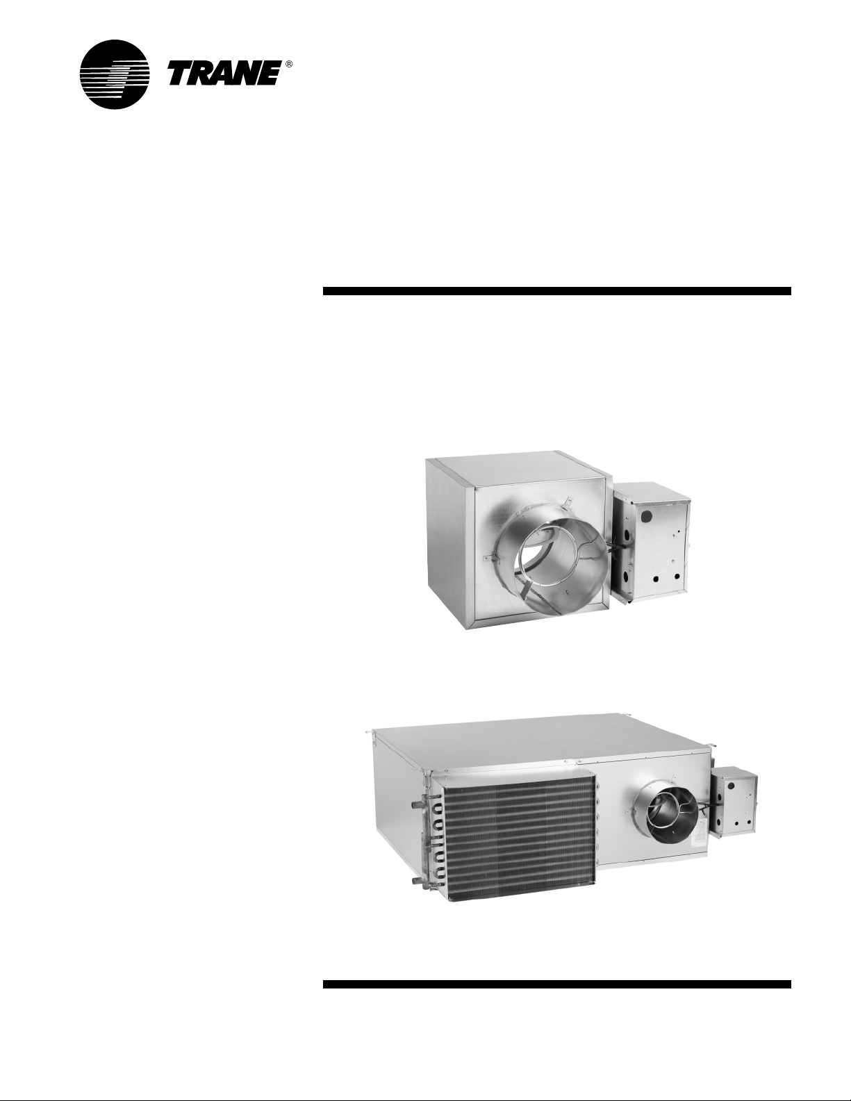
Installation/
Operator
Maintenance
VariTrane™ Single-Duct
and Fan-Powered Units
All VariTrane VAV Models with pneumatic, electronic, DDC controls and diffusers.
June 2006
VAV-SVN01E-EN
Page 2

© 2006 American Standard All rights reserved VAV-SVN01E-EN
Page 3

Contents
Service Model Number Description .................. 4 – 14
General Information ............................................... 15
Literature Contents
Receiving and Handling
Warnings and Cautions Explanations
Unit Information ............................................. 16 – 17
Single-Duct Units
Dual-Duct Units
Fan-Powered and Low-Height Units
Unit Installation .............................................. 18 – 31
Hanging Bracket Locations
Unit Weights
Water Coil Connections
Unit Accessibility
Clearances
Actuator Mounting
Unit Setup ...................................................... 32 – 46
Flow Sensor ∆P vs. Airflow Delivery
Maximum Fan Motor Amperage
(SCR) Motor Speed Control Adjustment Procedure
Electrically Commutated Motor (ECM)
ECM CFM Tables
Wiring Diagrams ............................................. 47 – 54
Maintenance .......................................................... 55
Motors
Fan Wheel
Filter
Water Coil
Fan Motor Replacement
Installation of Diffusers .......................................... 56
T-Bar Ceiling
Concealed Spline Ceiling
Drywall/Plaster Ceiling
VAV-SVN01E-EN 3
Page 4
Service Model
WARNING
Number Description
WARNING
Fiberglass Wool!
WARNING: ALL INSULATED UNITS
(except closed-cell foam insulation)
CONTAIN FIBERGLASS WOOL! Read
this literature prior to installation for
proper instruction. Disturbing the
insulation in this product during
installation, maintenance or repair will
expose you to airborne particles of
glass wool fibers and ceramic fibers
known to the state of California to
cause cancer through inhalation. Glass
wool fibers may also cause respiratory,
skin or eye irritation.
Single-Duct Units
Digit 1, 2—Unit Type
VC VariTrane single-duct
Digit 3—Reheat
C Cooling Only
E Electric Heat
W Hot Water Heat
Digit 4—Development Sequence
F Sixth
Digit 5, 6—Primary Air Valve
04 4" inlet (225 cfm)
05 5" inlet (350 cfm)
06 6" inlet (500 cfm)
08 8" inlet (900 cfm)
10 10" inlet (1400 cfm)
12 12" inlet (2000 cfm)
14 14" inlet (3000 cfm)
16 16" inlet (4000 cfm)
24 24" x 16" inlet (8000 cfm)
Digit 7, 8—Not Used
00 N/A
Digit 9—Not Used
0 N/A
Digit 10, 11—Design Sequence
H0 Fourth (factory assigned)
Digit 12, 13, 14, 15—Controls
ENON No controls, field-installed
DDC/electric
PNON No controls, field-installed
pneumatic
DD00 Trane elec actuator only
DD01 DDC – Cooling only
DD02 DDC – N.C. on/off water valve
control
DD03 DDC – Prop hot water valve
control
DD04 DDC – On/off electric heat
DD05 DDC – Pulse-width modulation
electric heat
DD07 DDC – N.O. on/off water valve
control
DD11 LonTalk DDC Controller—
Cooling only
DD12 LonTalk DDC Controller w/ N.C.
on/off hot water control
DD13 LonTalk DDC Controller w/
proportional hot water control
DD14 LonTalk DDC Controller–on/off
electric heat control
DD15 LonTalk DDC Controller w/
pulse-width modulation electric
heat control
DD17 LonTalk DDC Controller w/ N.O.
on/off hot water control
FM00 FM – Customer-supplied
actuator & controller
FM01 FM – Trane actuator w/ cusomer-
supplied control
VMA1 FM – Johnson controls VMA-1410
VMA2 FM – Johnson controls VMA-1420
PWR1 FM – Seimens 540-100 w/
GDE131.1P actuator
PWR4 FM – Seimens 540-100 w/ Trane
actuator
PWR5 FM – Seimens 540-100 w/
GDE131.1U actuator
AT01 FM – Automated Logic U341V+
AT02 FM – Automated Logic U141V+
EI05 Analog – With optional on/off
reheat
EI28 Analog – With optional on/off
reheat with dual-minimum cfm
EI29 Analog – With optional on/off
reheat with constant-volume cfm
PC00 PN – N.C. Trane pneumatic
actuator
PC04 PN – N.C. with optional on/off HW,
DA Stat
PC05 PN – N.C. with optional on/off
electric, RA Stat
PN00 PN – N.O. Trane pneumatic
actuator, RA Stat
PN04 PN – N.O. PVR, DA Stat
PN05 PN – N.O. PVR, RA Stat
PN11 PN – N.O. dual-minimum cfm,
DA Stat
PN32 PN – Water Valve, N.O. constant
volume, DA Stat
PN34 PN – Electric heat, N.O. constant
volume, DA Stat
Notes
:
N.C. = Normally-closed
N.O. = Normally-opened
DA Stat = Direct-acting pneumatic t-stat
(by others)
RA Stat = Reverse-acting pneumatic
PN = Pneumatic
FM = Factory installation of customer-
PVR = Pneumatic Volume Regulator
Digit 16—Insulation
A 1/2" Matte-faced
B 1" Matte-faced
C 1/2" Foil-faced
D 1" Foil-faced
F 1" Double-wall
G 3/8" Closed-cell
t-stat (by others)
supplied controller
4
VAV-SVN01E-EN
Page 5
Single-Duct Units (con't.)
Digit 17—Not Used
0 N/A
Digit 18—Not Used
0 N/A
Digit 19—Outlet Plenum (Connection is
Slip & Drive)
0 None
A 1 Outlet RH
B 1 Outlet END
C 1 Outlet LH
D 2 Outlets, 1 RH, 1 END
E 2 Outlets, 1 LH, 1 END
F 2 Outlets, 1 RH, 1 LH
H 3 Outlets, 1 LH, 1 RH, 1 END
J 4 Outlets, 1 LH, 1 RH, 2 END
Note
:
See unit drawings for outlet sizes/
damper information.
Digit 20—Not Used
0 N/A
Digit 21—Water Coil
0 None
11-Row
2 2-Row
Digit 22—Electrical Connections (VCCF,
VCWF can be flipped in the field to
achieve opposite-hand connection)
L Left (Airflow hitting you in the
face)
R Right (Airflow hitting you in the
face)
0 Opposite side connection – coil
and control
Service Model
Number Description
Digit 23—Transformer
0 None
1 120/24 volt (50 VA)
2 208/24 volt (50 VA)
3 240/24 volt (50 VA)
4 277/24 volt (50 VA)
5 480/24 volt (50 VA)
6 347/24 Volt (50 VA)
7 575/24 Volt (50 VA)
8 380/24 Volt (50 VA)
Note: For VCEF units with transformers
the VA depends on the staging, control,
and contactor type (ranges are 40 VA
to 75 VA)
Digit 24—Disconnect Switch
0 None
W With
Note: VCCF, VCWF – Toggle Disconnect
VCEF – Door Interlocking Power
Disconnect
Digit 25—Power Fuse
0 None
W With
Digit 26—Electric Heat Voltage
0 None
A 208/60/1
B 208/60/3
C 240/60/1
D 277/60/1
E 480/60/1
F 480/60/3
G 347/60/1
H 575/60/3
J 380/50/3
K 120/60/1
Notes
Digit 27, 28, 29—Electric Heat kW
000 None
050 0.5 kW
010 1.0 kW
015 1.5 kW
460 46.0 kW
:
0.5 to 8.0 kW – ½ kW increments
8.0 to 18.0 kW – 1 kW increments
18.0 to 46.0 kW – 2 kW increments
Digit 30—Electric Heat Stages
0 None
1 1 Stage
2 2 Stages Equal
3 3 Stages Equal
Digit 31—Contactors
0 None
1 24-volt magnetic
2 24-volt mercury
3 PE with magnetic
4 PE with mercury
Digit 32—Not Used
0 N/A
VAV-SVN01E-EN 5
Page 6
Dual-Duct Units
Digit 1, 2, 3—Unit Type
VDD VariTrane dual-duct
Digit 4—Development Sequence
F Sixth
Digit 5, 6—Primary Air Valve
05 5" inlet (350 cfm)
06 6" inlet (500 cfm)
08 6" inlet (900 cfm)
10 10" inlet (1400 cfm)
12 12" inlet (2000 cfm)
14 14" inlet (3000 cfm)
16 16" inlet (4000 cfm)
Digit 7, 8—Secondary Air Valve
05 5" inlet (350 cfm)
06 6" inlet (500 cfm)
08 8" inlet (900 cfm)
10 10" inlet (1400 cfm)
12 12" inlet (2000 cfm)
14 14" inlet (3000 cfm)
16 16" inlet (4000 cfm)
Digit 9—Not Used
0 N/A
Digit 10, 11—Design Sequence
C0 Third (factory assigned)
Digit 12, 13, 14, 15—Controls
ENON No Controls, Field-installed
DDC/Electric
PNON No Controls, Field-installed
Pneumatic
DD00 Trane elec actuator only
DD01 DDC – Cooling only
DD08 DDC – Constant-volume
discharge
DD11 LonTalk DDC Controller—
Cooling only
DD18 LonTalk DDC Controller—
Constant Volume Discharge
Service Model
Number Description
FM00 FM – Customer-supplied
actuator & controller
FM01 FM – Trane actuator w/
customer-supplied controller
PC03 PN – N.C. heating/ N.O. cooling
w/ PVRs, DA stat
PN08 PN – N.O. heating/ N.O. cool
act. only, RA stat
PN09 PN – N.O. htg/clg vlvs w/ PVRs,
DA stat
PN10 PN – N.O. htg/clg w/ PVRs (cv
disch), DA stat.
Notes:
N.C. = Normally-closed
N.O. = Normally-opened
DA Stat = Direct-acting pneumatic t-stat
(by others)
RA Stat = Reverse-acting pneumatic t-stat
(by others)
PN = Pneumatic
FM = Factory installation of customer-
supplied controller
PVR = Pneumatic Volume Regulator
Digit 16—Insulation
A 1/2" Matte-faced
B 1" Matte-faced
C 1/2" Foil-faced
D 1" Foil-faced
F 1" Double-wall
G 3/8" Closed-cell
Digit 17—Not Used
0 N/A
Digit 18—Not Used
0 N/A
Digit 19—Outlet Plenum (Connection is
slip & drive)
0 none
A 1 outlet–RH
B 1 outlet–END
C 1 outlet–LH
D 2 outlets–1 RH, 1 END
E 2 outlets–1 LH, 1 END
F 2 outlets–1 RH, 1 LH
G 2 outlets - END
H 3 outlets–1 LH, 1 RH, 1 END
J 4 outlets–1 LH, 1 RH, 2 END
Note: See unit drawings for outlet sizes/
damper information.
Digit 20—Not Used
0 N/A
Digit 21—Not Used
0 N/A
Digit 22—Not Used
0 N/A
Digit 23—Transformer
0 None
1 120/24 volt (50 VA)
2 208/24 volt (50 VA)
3 240/24 volt (50 VA)
4 277/24 volt (50VA)
5 480/24 volt (50 VA)
6 347/24 volt (50 VA)
7 575/24 volt (50 VA)
Digit 24—Disconnect Switch
0 None
W With Toggle
Digit 25—Power Fuse
0 None
W With
6
VAV-SVN01E-EN
Page 7
Fan-Powered Parallel Units
Digit 1, 2—Unit Type
VP VariTrane fan-powered parallel
Digit 3—Reheat
C Cooling Only
E Electric Heat
W Hot Water Heat
Digit 4—Development Sequence
F Sixth
Digit 5, 6—Primary Air Valve
05 5" inlet (350 max cfm)
06 6" inlet (500 max cfm)
08 8" inlet (900 max cfm)
10 10" inlet (1400 max cfm)
12 12" inlet (2000 max cfm)
14 14" inlet (3000 max cfm)
16 16" inlet (4000 max cfm)
Digit 7, 8—Secondary Air Valve
00 N/A
Digit 9—Fan
P 02SQ fan (500 nominal cfm)
Q 03SQ fan (1100 nominal cfm)
R 04SQ fan (1350 nominal cfm)
S 05SQ fan (1550 nominal cfm)
T 06SQ fan (1850 nominal cfm)
U 07SQ fan (2000 nominal cfm)
Digit 10, 11—Design Sequence
J0 Design Sequence (Factory
assigned)
Digit 12, 13, 14, 15—Controls
ENON No controls, field-installed DDC
or analog
ENCL ENON with controls enclosure
PNON No controls, field-installed
pneumatic
DD00 Trane elec actuator only
DD01 DDC – cooling only
DD02 DDC – N.C. on/off water control
DD03 DDC – prop hot water control
DD04 DDC – on/off electric heat
control
DD05 DDC – pulse-width modulation
electric heat control
DD07 DDC – N.O. on/off hot water
control
DD11 LonTalk DDC Controller—
Cooling only
DD12 LonTalk DDC Controller w/ N.C.
on/off hot water control
DD13 LonTalk DDC Controller w/
proportional hot water control
DD14 LonTalk DDC Control–on/off
electric heat control
Service Model
Number Description
DD15 LonTalk DDC Controller w/
pulse-width modulation electric heat
control
DD17 LonTalk DDC Controller w/ N.O.
on/off hot water control
FM00 FM customer actuator & control
FM01 FM Trane actuator w/ customersupplied controller
VMA2 FM Johnson Controls
VMA-1420
PWR1 FM Seimens 540-100 w/
GDE131.1P actuator
PWR4 FM Seimens 540-100 w/ Trane
actuator
PWR5 FM Seimens 540-100 w/
GDE131.1U actuator
AT01 FM Automated Logic U341V+
AT02 FM Automated Logic U141V+
EI05 Analog – fan-powered parallel
with optional on/off reheat
PN00 PN – N.O. Trane pneumatic
actuator, R.A. stat
PN05 PN – N.O. PVR, R.A. stat
Notes:
N.C. = Normally-closed
N.O = Normally-opened
DA Stat = Direct-acting pneumatic t-stat
(by others)
RA Stat = Reverse-acting pneumatic
t-stat (by others)
PN = Pneumatic
FM = Factory installation of customer-
supplied controller
PVR = Pneumatic Volume Regulator
Digit 16—Insulation
A 1/2" Matte-faced
B 1" Matte-faced
C 1/2" Foil-faced
D 1" Foil-faced
F 1" Double-wall
G 3/8" Closed-cell
Digit 17—Motor Type
D PSC Motor
E High-efficiency motor (ECM)
Digit 18—Motor Voltage
1 115/60/1
2 277/60/1
3 347/60/1
4 208/60/1
5 230/50/1
Digit 19—Outlet Connection
1 Flanged
2 Slip & Drive
Electrical Connections Note: Airflow
hitting you in the face.
Note: VPCF, VPWF – Toggle Disconnect
Electric Heat Voltage Notes:
0.5 to 8.0 kW–½ kW increments
8.0 to 18.0 kW –1 kW increments
18.0 to 46.0 kW–2 kW increments
Digit 20—Attenuator
0 None
W With
Digit 21—Water Coil
0 None
1 1-Row–Plenum inlet installed RH
2 2-Row–Plenum inlet installed RH
3 1-Row–Discharge installed, LH
4 1-Row–Discharge installed, RH
5 2-Row–Discharge installed, LH
6 2-Row–Discharge installed, RH
Digit 22—Electrical Connections
L Left
R Right
Digit 23—Transformer
0 N/A (provided as standard)
Digit 24—Disconnect Switch
0 None
W With
VPEF – Door Interlocking Power
Disconnect
Digit 25—Power Fuse
0 None
W With
Digit 26—Electric Heat Voltage
0 None
A 208/60/1
B 208/60/3
C 240/60/1
D 277/60/1
E 480/60/1
F 480/60/3
G 347/60/1
H 575/60/3
J 380/50/3
K 120/60/1
Digit 27, 28, 29—Electric Heat Voltage
000 None
050 0.5 kW
010 1.0 kW
015 1.5 kW
260 26.0 kW
VAV-SVN01E-EN 7
Page 8

Fan-Powered Parallel Units (con't)
Digit 30—Electric Heat Stages
0 None
1 1 Stage
2 2 Stages Equal
3 3 Stages Equal
Digit 31—Contactors
0 None
1 24-volt magnetic
2 24-volt mercury
3 PE with magnetic
4 PE with mercury
Digit 32—Airflow Switch
0 None
W With
Service Model
Number Description
8
VAV-SVN01E-EN
Page 9
Fan-Powered Series Units
Digit 1, 2—Unit Type
VS VariTrane fan-powered series
Digit 3—Reheat
C Cooling Only
E Electric Heat
W Hot Water Heat
Digit 4—Development Sequence
F Sixth
Digit 5, 6—Primary Air Valve
04 4" inlet (225 max cfm)
05 5" inlet (350 max cfm)
06 6" inlet (500 max cfm)
08 8" inlet (900 max cfm)
10 10" inlet (1400 max cfm)
12 12" inlet (2000 max cfm)
14 14" inlet (3000 max cfm)
16 16" inlet (4000 max cfm)
Digit 7, 8—Secondary Air Valve
00 N/A
Digit 9—Fan
P 02SQ fan (700 nominal cfm)
Q 03SQ fan (1200 nominal cfm)
R 04SQ fan (1550 nominal cfm)
S 05SQ fan (1900 nominal cfm)
T 06SQ fan (2600 nominal cfm)
U 07SQ fan (3000 nominal cfm)
Fan Note: See fan curves for specific
airflows
Digit 10, 11—Design Sequence
J0 Design Sequence
(Factory assigned)
Digit 12, 13, 14, 15—Controls
ENON No controls, field-installed DDC
or analog
ENCL ENON with control enclosure
PNON No controls, field-installed
pneumatic
DD00 Trane elec actuator only
DD01 DDC – cooling only
DD02 DDC – N.C. on/off water control
DD03 DDC – prop hot water control
DD04 DDC – on/off electric heat
control
DD05 DDC – pulse-width modulation
electric heat control
DD07 DDC N.O. on/off hot water
control
DD11 LonTalk DDC Controller—
Cooling only
DD12 LonTalk DDC Controller w/ N.C.
on/off hot water control
Service Model
Number Description
DD13 LonTalk DDC Controller w/
proportional hot water control
DD14 LonTalk DDC Controller–on/off
electric heat control
DD15 LonTalk DDC Controller w/
pulse-width modulation electric
heat control
DD17 LonTalk DDC Controller w/ N.O.
on/off hot water control
FM00 FM customer actuator & control
FM01 FM Trane actuator w/ customer-
supplied controller
VMA2 FM Johnson controls VMA-1420
PWR1 FM Seimens 540-100 w/
GDE131.1P actuator
PWR4 FM Seimens 540-100 w/ Trane
actuator
PWR5 FM Seimens 540-100 w/
GDE131.1U actuator
AT01 FM Automated Logic U341V+
AT02 FM Automated Logic U141V+
EI71 Analog fan-powered series
with optional on/off reheat
PN00 PN – N.O. Trane pneumatic
actuator, R.A. stat
PN51 PN – N.O. PVR, duct pressure
switch, R.A. stat
PN52 PN – N.O. PVR, dual pressure
main, R.A. stat
Notes:
N.C. = Normally-closed
N.O. = Normally-opened
DA Stat = Direct-acting pneumatic t-stat
(by others)
RA Stat = Reverse-acting pneumatic t-stat
(by others)
PN = Pneumatic
FM = Factory installation of customer-
supplied controller
PVR = Pneumatic Volume Regulator
Digit 16—Insulation
A 1/2" Matte-faced
B 1" Matte-faced
C 1/2" Foil-faced
D 1" Foil-faced
F 1" Double-wall
G 3/8" Closed-cell
Digit 17—Motor Type
D PSC Motor
E High-efficiency motor (ECM)
Water Coil and Electrical Connections
Note: Airflow hitting you in the face.
Note: VSCF, VSWF – Toggle Disconnect
Digit 18—Motor Voltage
1 115/60/1
2 277/60/1
3 347/60/1
4 208/60/1
5 230/50/1
Digit 19—Outlet Connection
1 Flanged
2 Slip & Drive
Digit 20—Attenuator
0 None
W With
Digit 21—Water Coil
0 None
3 1-Row–Discharge installed, LH
4 1-Row–Discharge installed, RH
5 2-Row–Discharge installed, LH
6 2-Row–Discharge installed, RH
Digit 22—Electrical Connections
L Left
R Right
Digit 23—Transformer
0 N/A (provided as standard)
Digit 24—Disconnect Switch
0 None
W With
VSEF – Door Interlocking Power
Disconnect
Digit 25—Power Fuse
0 None
W With
Digit 26—Electric Heat Voltage
0 None
A 208/60/1
B 208/60/3
C 240/60/1
D 277/60/1
E 480/60/1
F 480/60/3
G 347/60/1
H 575/60/3
J 380/50/3
K 120/60/1
VAV-SVN01E-EN 9
Page 10

Fan-Powered Series Units (con't)
Digit 27, 28, 29—Electric Heat Kilowatts
000 None
050 0.5 kW
010 1.0 kW
015 1.5 kW
240 24.0 kW
Digit 30—Electric Heat Stages
0 None
1 1 Stage
2 2 Stages Equal
3 3 Stages Equal
Digit 31—Contactors
0 None
1 24-volt magnetic
2 24-volt mercury
3 PE with magnetic
4 PE with mercury
Digit 32—Airflow Switch
0 None
W With
Service Model
Number Description
10
VAV-SVN01E-EN
Page 11

Service Model
Number Description
Fan-Powered Low-Height Parallel Units
Digit 1, 2—Unit Type
LP VariTrane fan-powered low-
height parallel
Digit 3—Reheat
C Cooling Only
E Electric Heat
W Hot Water Heat
Digit 4—Development Sequence
F Sixth
Digit 5, 6—Primary Air Valve
05 5" inlet (350 maximum cfm)
06 6" inlet (500 maximum cfm)
08 8" inlet (900 maximum cfm)
RT 8" x 14" inlet (1800 maximum cfm)
Digit 7, 8—Secondary Air Valve
00 N/A
Digit 9—Fan
V 08SQ 500 nominal cfm
W 09SQ 900 nominal cfm
X 10SQ 1800 nominal cfm
Digit 10, 11—Design Sequence
K0 Sixth (factory assigned)
Digit 12, 13, 14, 15—Controls
ENON No controls, field-installed DDC/
electric
PNON No controls, field-installed
pneumatic
DD00 Trane elec actuator only
DD01 DDC – cooling only
DD02 DDC – N.C. on/off water valve
control
DD03 DDC – prop hot water valve
control
DD04 DDC – on/off electric heat control
DD05 DDC – pulse-width modulation
control
DD07 DDC – N.O. on/off water valve
control
DD11 LonTalk DDC Controller—Cooling
only
DD12 LonTalk DDC Controller w/ N.C.
on/off hot water control
DD13 LonTalk DDC Controller w/
proportional hot water control
DD14 LonTalk DDC Controller–on/off
DD15 LonTalk DDC Controller w/
pulse- width modulation
electric heat control
DD17 LonTalk DDC Controller w/ N.O.
FM00 FM customer actuator & control
FM01 FM Trane actuator w/ customer-
VMA2 FM Johnson Controls VMA1420
PWR1 FM Seimens 540-100 w/
PWR4 FM Seimens 540-100 w/ Trane
PWR5 FM Seimens 540-100 w/
AT01 FM Automated Logic U341V+
AT02 FM Automated Logic U141V+
EI05 Analog – fan-powered parallel
PN00 PN – N.O. Trane pneumatic
PN05 PN – N.O. PVR, R.A. stat
Notes:
N.C. = Normally-closed
N.O. = Normally-opened
DA Stat = Direct-acting pneumatic t-stat
RA Stat = Reverse-acting pneumatic t-stat
PN = Pneumatic
FM = Factory installation of customer-
PVR = Pneumatic Volume Regulator
Digit 16—Insulation
A 1/2" Matte-faced
B 1" Matte-faced
C 1/2" Foil-faced
D 1" Foil-faced
F 1" Double-wall
G 3/8" Closed-cell
Digit 17—Motor Type
D PSC Motor
E High-efficiency motor (ECM)
electric heat control
on/off hot water control
supplied controller
GDE131.1P actuator
actuator
GDE131.1U actuator
with optional on/off reheat
actuator, R.A. stat
(by others)
(by others)
supplied controller
Digit 18—Motor Voltage
1 115/60/1
2 277/60/1
3 347/60/1
5 230/50/1
Digit 19—Outlet Connection
1 Flanged
2 Slip & Drive
Digit 20—Not Used
0 N/A
Digit 21—Water Coil
0 None
1 1-Row–Plenum inlet installed
2 2-Row–Plenum inlet installed
3 1-Row–Discharge installed, LH
4 1-Row–Discharge installed, RH
5 2-Row–Discharge installed, LH
6 2-Row–Discharge installed, RH
Digit 22—Electrical Connections
L Left (airflow hitting you in the face)
Digit 23—Transformer
0 N/A (provided as standard)
Digit 24—Disconnect Switch
0 None
W With
Note: LPCF, LPWF – Toggle Disconnect
LPEF – Door Interlocking Power
Disconnect
Digit 25—Power Fuse
0 None
W With
Digit 26—Electric Heat Voltage
0 None
A 208/60/1
B 208/60/3
C 240/60/1
D 277/60/1
E 480/60/1
F 480/60/3
G 347/60/1
H 575/60/3
J 380/50/3
VAV-SVN01E-EN 11
Page 12

Service Model
Number Description
Fan-Powered Low-Height Parallel Units (con't)
Digit 27, 28, 29—Electric Heat Voltage
000 None
005 0.5 kW
010 1.0 kW
015 1.5 kW
020 2.0 kW
025 2.5 kW
030 3.0 kW
035 3.5 kW
040 4.0 kW
045 4.5 kW
050 5.0 kW
055 5.5 kW
060 6.0 kW
065 6.5 kW
070 7.0 kW
075 7.5 kW
080 8.0 kW
090 9.0 kW
100 10.0 kW
110 11.0 kW
120 12.0 kW
130 13.0 kW
140 14.0 kW
Digit 30—Electric Heat Stages
0 None
1 1 Stage
2 2 Stages Equal
Digit 31—Contactors
0 None
1 24-volt magnetic
2 24-volt mercury
3 PE with magnetic
4 PE with mercury
Digit 32—Airflow Switch
0 None
W With
12
VAV-SVN01E-EN
Page 13

Service Model
Number Description
Fan-Powered Low-Height Series Units
Digit 1, 2—Unit Type
LS VariTrane low-height series fanpowered
Digit 3—Reheat
C Cooling Only
E Electric Heat
W Hot Water Heat
Digit 4—Development Sequence
F Sixth
Digit 5, 6—Primary Air Valve
05 5" inlet (350 cfm)
06 6" inlet (500 cfm)
08 8" inlet (900 cfm)
RT (8" x 14" inlet (1800 cfm)
Digit 7, 8—Secondary Air Valve
00 N/A
Digit 9—Fan
V 08SQ 500 nominal cfm
W 09SQ 900 nominal cfm
X 10SQ 1800 nominal cfm
Digit 10, 11—Design Sequence
K0 Sixth (factory assigned)
Digit 12, 13, 14, 15—Controls
ENON No controls, field-installed DDC/
electric
PNON No controls, field-installed
pneumatic
DD00 Trane elec actuator only
DD01 DDC – cooling only
DD02 DDC – N.C. on/off water valve
control
DD03 DDC – prop hot water valve
control
DD04 DDC – on/off electric heat
control
DD05 DDC – pulse-width modulation
control
DD07 DDC – N.O. on/off water valve
control
DD11 LonTalk DDC Controller—
Cooling only
DD12 LonTalk DDC Controller w/ N.C.
on/off hot water control
DD13 LonTalk DDC Controller w/
proportional hot water control
DD14 LonTalk DDC Controller–on/off
DD15 LonTalk DDC Controller w/
DD17 LonTalk DDC Controller w/ N.O.
FM00 FM customer actuator & control
FM01 FM Trane actuator w/ customer-
VMA2 FM Johnson controls VMA-1420
PWR1 FM Seimens 540-100 w/
PWR4 FM Seimens 540-100 Trane
PWR5 FM Seimens 540-100 w/
AT01 FM Automated Logic U341V+
AT02 FM Automated Logic U141V+
EI71 Analog – Series fan-powered
PN00 PN – N.O. Trane pneumatic
PN51 PN – N.O. PVR, duct pressure
PN52 PN – N.O. PVR, dual pressure
Notes:
N.C. = Normally-closed
N.O. = Normally-opened
DA Stat = Direct-acting pneumatic t-stat
RA Stat = Reverse-acting pneumatic
PN = Pneumatic
FM = Factory installation of customer-
PVR = Pneumatic Volume Regulator
Digit 16—Insulation
A 1/2" Matte-faced
B 1" Matte-faced
C 1/2" Foil-faced
D 1" Foil-faced
F 1" Double-wall
G 3/8" Closed-cell
electric heat control
pulse-width modulation electric
heat control
on/off hot water control
supplied controller
GDE131.1P actuator
actuator
GDE131.1U actuator
on/off reheat
actuator, R.A. stat
switch, R.A. stat
main, R.A. stat
(by others)
t-stat (by others)
supplied controller
Digit 17—Motor Type
D PSC Motor
E High-efficiency motor (ECM)
Digit 18—Motor Voltage
1 115/60/1
2 277/60/1
3 347/60/1
5 230/50/1
Digit 19—Outlet Connection
1 Flanged
2 Slip & Drive
Digit 20—Not Used
0 N/A
Digit 21—Water Coil
0 None
3 1-Row–Discharge installed, LH
4 1-Row–Discharge installed, RH
5 2-Row–DIscharge installed, LH
6 2-Row–Discharge installed, RH
Digit 22—Electrical Connections
L Left (airflow hitting you in the face)
R Right (airflow hitting you in the face)
Digit 23—Transformer
0 N/A (provided as standard)
Digit 24—Disconnect Switch
0 None
W With
Note: LSCF, LSWF – Toggle Disconnect
LSEF – Door Interlocking Power
Disconnect
Digit 25—Power Fuse
0 None
W With
Digit 26—Electric Heat Voltage
0 None
A 208/60/1
B 208/60/3
C 240/60/1
D 277/60/1
E 480/60/1
F 480/60/3
G 347/60/1
H 575/60/3
J 380/50/3
VAV-SVN01E-EN 13
Page 14

Service Model
Number Description
Fan-Powered Low-Height Series Units (con't)
Digit 27, 28, 29—Electric Heat Voltage
000 None
005 0.5 kW
010 1.0 kW
015 1.5 kW
020 2.0 kW
025 2.5 kW
030 3.0 kW
035 3.5 kW
040 4.0 kW
045 4.5 kW
050 5.0 kW
055 5.5 kW
060 6.0 kW
065 6.5 kW
070 7.0 kW
075 7.5 kW
080 8.0 kW
090 9.0 kW
100 10.0 kW
110 11.0 kW
120 12.0 kW
130 13.0 kW
140 14.0 kW
150 15.0 kW
160 16.0 kW
170 17.0 kW
180 18.0 kW
Digit 30—Electric Heat Stages
0 None
1 1 Stage
2 2 Stages Equal
Digit 31—Contactors
0 None
1 24-Volt magnetic
2 24-Volt mercury
3 PE with magnetic
4 PE with mercury
Digit 32—Air Flow Switch
0 None
W With
14
VAV-SVN01E-EN
Page 15
General
WARNING
CAUTION
CAUTION
Information
Literature Contents
This manual describes the installation
of VariTrane VAV units with recommended wiring, piping, and mounting
of Single-Duct, Dual-Duct, Fan-Powered, Low-Height terminal units and
diffusers.
Receiving and Handling
VariTrane Units are shipped completely
assembled with the exceptions of
optional attenuators for fan-powered
units and accessories.
Upon receiving the equipment,
complete the following:
y Locate the nameplate and refer to the
model and sales order number and
check that the correct units have been
delivered.
y Inspect the control enclosures and air
valve casing for dents or punctures.
y Verify that all options have been
included, such as filters, controls,
heating coils, water valves, etc. Also
check that the unit voltages agree with
the building parameters.
y Manually rotate the fan (if applicable) to
assure that there are no obstructions
within the housing.
y Claims for in-transit damage must be
filed immediately with the delivery
carrier.
y For hot water re-heat units, check the
coil fins and make sure that coils are
not damaged.
y Locate and verify that the correct zone
sensors are with the order. These will be
marked with an orange “Accessories
Enclosed” label. Store in a secure
location until needed. Accessories lost
at the jobsite are NOT covered by
Trane’s warranty.
y If a discrepancy occurs between what
was ordered and what is received,
contact you local Trane representative
immediately.
y Read the appropriate section in this
manual for installation procedures prior
to actual starting of equipment.
Upon receiving the equipment, please
inspect each unit and components for
external or internal damage. Refer to
the bill of lading to insure all equipment
and accessories have been received.
Contact your local Trane sales
representative and notify the trucking
company immediately of any short ship
or damaged equipment.
NOTICE:
Warnings and Cautions appear at appropriate sections throughout this manual.
Read these carefully.
WARNING
– Indicates a potentially hazardous situation which, if
not avoided, could result in death or serious injury.
CAUTION
– Indicates a potentially hazardous situation which, if
not avoided, may result in minor or moderate injury. It may also be used
to alert against unsafe practices.
CAUTION
– Indicates a situation that may result in equipment or
property-damage-only accidents.
VAV-SVN01E-EN 15
Page 16
Unit
Information
Single-Duct Units
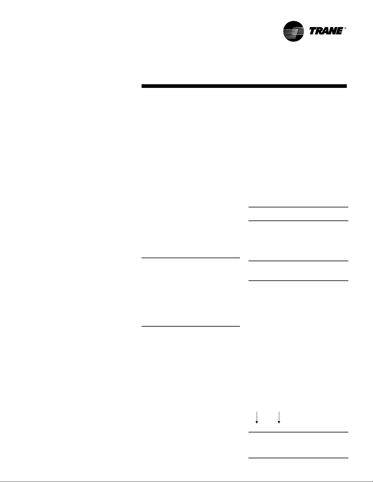
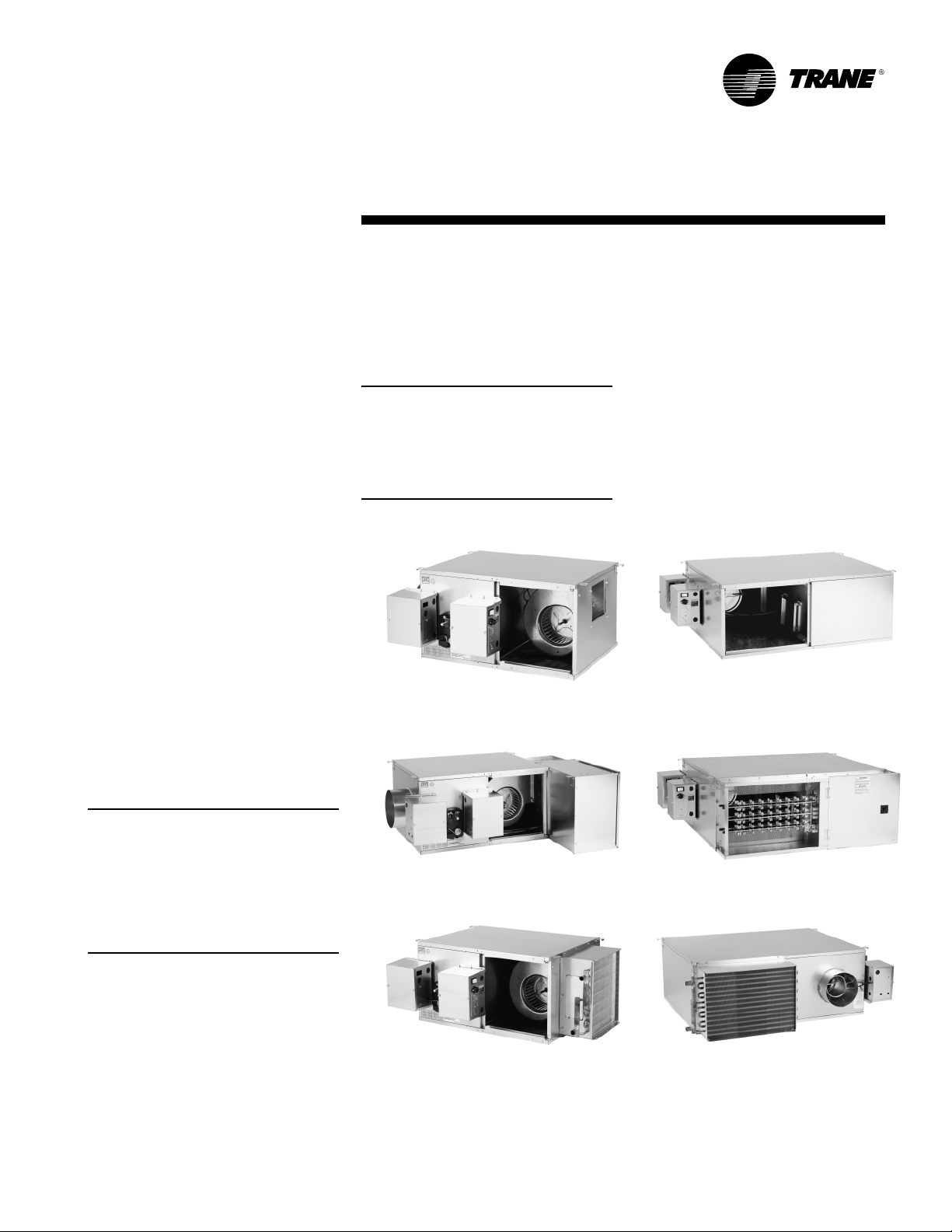
The basic unit consists of a sheet metal
casing with an air valve, which is used
to modulate the air being delivered into
the occupied zone. The unit is designed
to modulate either cooling or heating
air between the temperatures of 40°F
and 140°F. Air enters the air valve
through the round or rectangular inlet
and exits into the sheet metal casing to
be distributed to the zone either
through integral round outlets in the
casing or through rectangular duct
attached to the discharge of the unit.
The basic unit can also be ordered with
factory-mounted electric or hot water
heating coils attached to the discharge.
(See Figure 1.)
These re-heat units are used primarily
to reheat air-to-zone temperature when
the load in the occupied space is low.
Primary air is modulated through the
VariTrane air valve by rotating the
damper blade. All air valves have a
round/rectangular inlet for easy fit-up
with incoming ductwork.
Figure 1 – Typical Single-Duct Units
VCCF
VCWF
VCEF
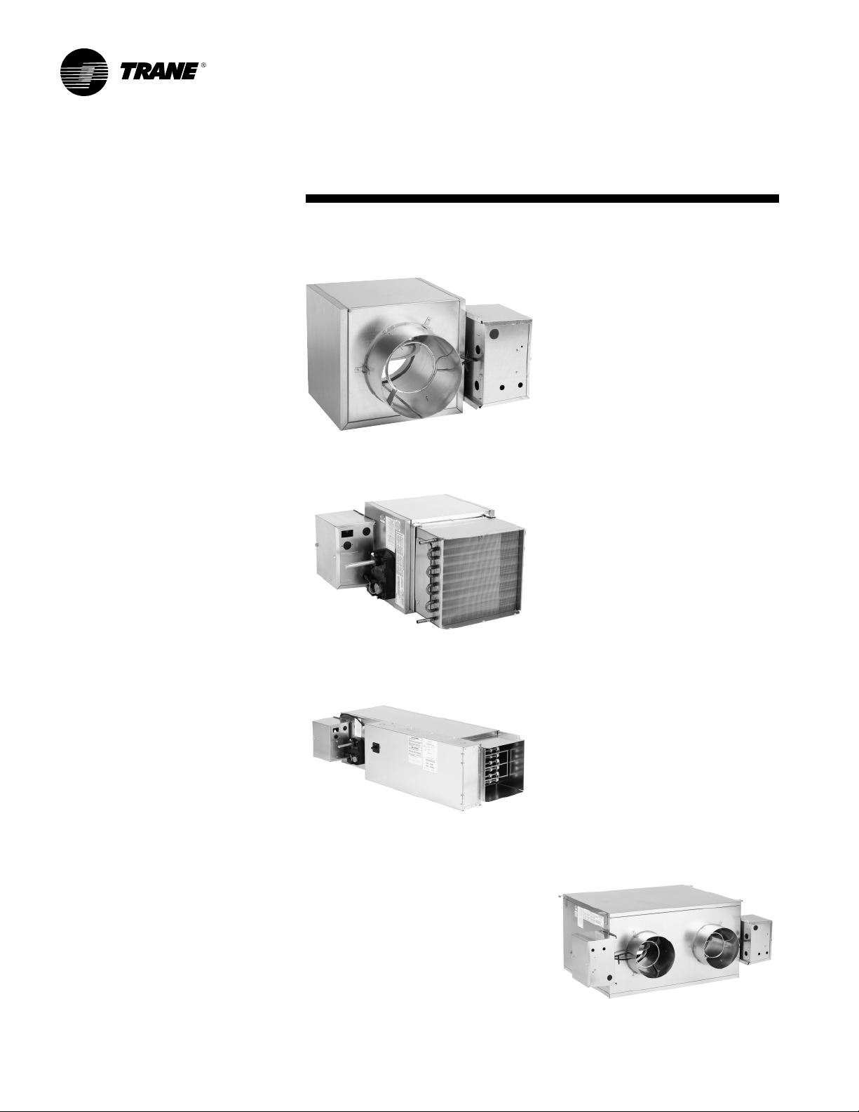
Dual-Duct Units
Dual-duct units provide two air valves:
one as heating primary air and the
other as cooling primary air. Both
discharge into the common outlet,
which leads to the zone being controlled. (See Figure 2.)
The units are provided with a slip and
drive rectangular duct connection or
can be ordered with integral outlet
plenum.
Sequencing of the hot and cold air
valve is dependent upon job
requirements. One typical control is the
valves working in conjunction with each
other to respond to zone temperature.
When the cooling valve becomes fully
closed or reaches a specified minimum,
then the heating valve will begin to
modulate or vice versa. The typical
result is that air flowing to the zone
varies from the maximum down to a
minimum and back up to a maximum
as the load varies and as the controls
would cause one air valve to close and
the other to open.
Another typical application is when the
unit provides a constant volume to the
zone. When the zone sensor is tied
directly to the heating valve, it will
modulate the heating valve according
to the zone temperature.
When the heating valve is fully closed
or there is a call for cooling in the zone,
the cooling valve will be at constant
supply. As the space becomes too cool,
the heating valve will modulate open,
decreasing the cooling valve flow. The
typical result is that the air flowing into
the zone stays at a constant flow
whether the unit is heating or cooling.
Figure 2 – Typical Dual-Duct Unit
VDDF
16
VAV-SVN01E-EN
Page 17
Unit
Information
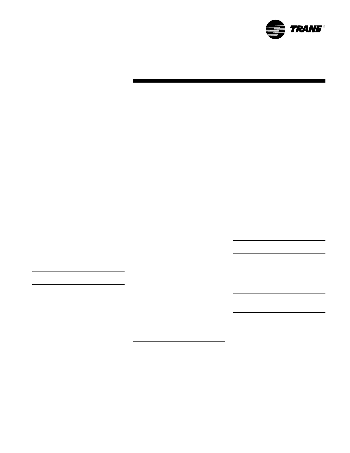
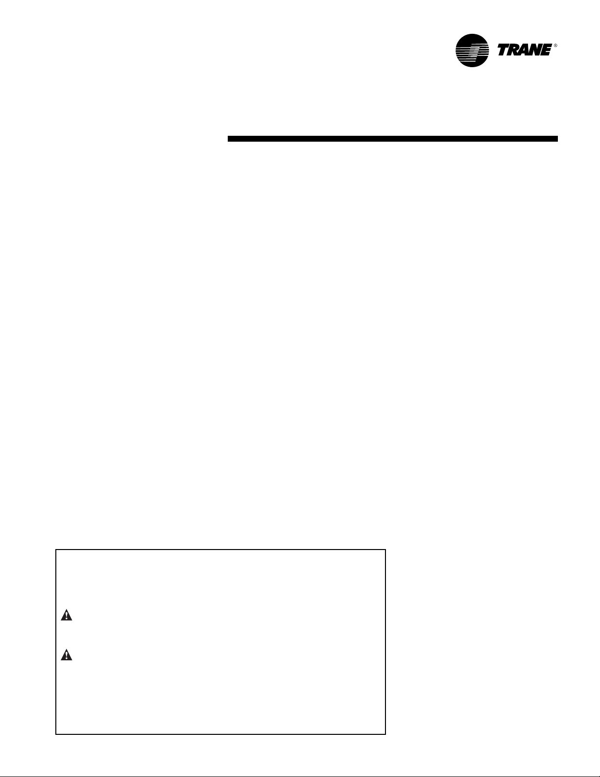
Fan-Powered and Fan-Powered
Low-Height Units
VariTrane fan-powered and low-height
fan-powered units can be either parallel
or series, with or without re-heat. (See
Figure 3.)
The fan on a series unit runs
continuously whenever the main air
handler unit is in operation. There are
various options for starting the fan. The
fan can be started three ways: 1)
remotely, 2) by a duct pressure switch,
or 3) by a combination of both. The
particular fan control method may vary
from unit to unit, depending upon job
needs.
Typically, the heater is off while the air
valve modulates primary air and
responds to zone temperature. If zone
temperature decreases to the point
where a decrease in primary air will not
maintain the desired temperature, the
re-heat will be activated to increase the
temperature of the discharge air.
On a parallel unit, the VariTrane air valve
delivers primary cooling air to the unit
outlet. When the space temperature
decreases beyond air valve control, the
fan is turned on as the first stage of
heat. The fan delivers plenum air from
above the occupied space to the unit
outlet, which is mixed with primary air
and delivered to the occupied space.
VariTrane fan-powered unit fan sizes
02SQ–05SQ and 08SQ–10SQ were
performance tested at .12 in. w.g. and
sizes 06SQ and 07SQ were tested at .15
in. w.g. Units are not designed to
operate unducted and below these
tested static pressures.
Note: Fan-powered units are available
with rectangular discharge connection
only. The optional heater is mounted on
the discharge of the unit. Hot water coils
are connected to either the plenum inlet
or on the discharge on parallel units, and
to the discharge of series units.
Figure 3 – Typical Fan-Powered Units
VSCF
VPCF
Note: Either the fan, the air valve, or both
can deliver airflow into the occupied
space. In order to prevent primary airflow
from exiting through the fan when the
fan is not running on a parallel unit, a
back draft damper is provided. When the
fan is not running, the efficiency of this
system is the same as a standard singleduct VAV unit.
Typically, the control systems applied to
parallel units cause the air valve to
close to zero or a minimum flow before
the fan is activated. After the fan is
activated, the optional heat will be
activated upon further reduction in
zone temperature. Therefore, minimal
primary air is mixed with the heated air.
VAV-SVN01E-EN 17
VSEF
VSWF
VPEF
VPWF
Page 18
Unit
Installation
Due to their weight, the VAV terminal
units should be suspended from the
uppermost ceiling, independent of the
false ceiling grid. Suspension devices
are to be supplied by the installer. Units
must be installed level and upright.
Failure to level the unit properly may
prevent proper operation of the
controls and/or terminal unit. Units are
not designed to be installed vertically.
Consequently, this will also void the UL
ratings and any warranty on the unit.
Single-Duct
Depending upon the size and weight of
the single-duct unit, it may be capable
of being supported by the ductwork
that is connected to it. No hanger
brackets are provided on these units
since the unit should be supported by
means of a hanger strap. The hanger
strap should be secured directly to the
unit casing as shown in Figure 4.
For cooling only single-duct units or
single-duct units with hot water coil, the
unt may be rotated 180° for opposite
side connections.
For units with electric heat, the unit
must be ordered from the factory
designating either right- or left-hand
connections.
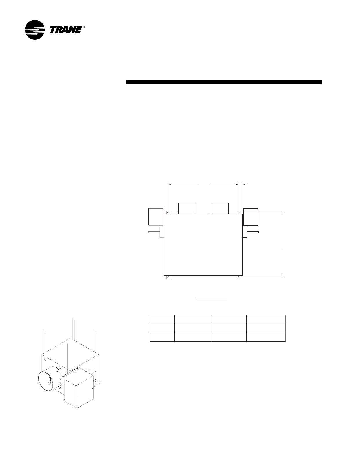
Dual-Duct
Dual-duct units should be supported by
either hanger straps or by using a
threaded rod in conjunction with the
hanger brackets that are provided on
the unit. See Figure 5.
Figure 5
Dual-Duct Hanger Bracket Locations
AIR
VALV E
COOLING
AIR
VALV E
HEATING
CA
B
Figure 4
Single-Duct Hanging
Recommendations
18
Inlet Size
5" thru 10"
12" thru 16"
TOP VIEW
BCA
25.25" (641 mm)23.154" (588 mm)
25.154" (639 mm) 1.376" (35 mm)
37.25" (946 mm)
1.376" (35 mm)
VAV-SVN01E-EN
Page 19

Unit
Installation
Fan-Powered (Standard and LowHeight)
Fan-powered units should be supported by either hanger straps or by
using a threaded rod in conjunction
with the hanger brackets that are
provided on the unit. Care should be
exercised to insure that the hanging
straps do not block the side access
panel. See Figures 6–13.
Figure 6
Parallel Hanger Bracket Locations Sizes
C
Wate r
Coil
TOP VIEW
Parallel Cooling & Hot Water
Flow Ring
Tubing
FAN SIZE
02SQ
03SQ, 04SQ, 05SQ
06SQ, 07SQ
26.75" (679 mm)
29.75" (756 mm)
36.75" (933 mm)
Primary
Airflow
Air
Valv e
Airflow
Discharge Outlet
ADE
26.75" (679 mm)
26.75" (679 mm)
26.75" (679 mm)
Optional Attenuator
B
Airflow
Plenum Inlet
Field Installed
41.154" (1041 mm)
41.154" (1041 mm)
41.154" (1041 mm)
EF
C
A
B
D
3.25" (83 mm)
3.25" (83 mm)
3.25" (83 mm)
20.00" (508 mm)
20.00" (508 mm)
20.00" (508 mm)
F
38.95" (989 mm)
38.95" (989 mm)
38.95" (989 mm)
C
Airflow
Plenum Inlet
Optional Attenuator
Field Installed
A
EF
D
TOP VIEW
Parallel Electric Heat
Flow Ring
Tubing
Primary
Airflow
Air
Valv e
Terminal Box
Heater
Airflow
Discharge Outlet
43.546
(1106 mm)
VAV-SVN01E-EN 19
B
Page 20

Figure 7
Series Hanger Bracket Locations
Unit
Installation
Flow Ring
Tubing
E
2.
Fan Inlet w/o
Attenuator
1.625"
(41 mm)
FAN SIZE
18.75" (476 mm)
03SQ, 04SQ
05SQ 27.25" (692 mm)
06SQ, 07SQ
20.75" (527 mm)
27.25" (692 mm)
Series Electric Heat
A
Air
Valve
Wate r
Coil
ADE
TOP VIEW
B
26.75" (679 mm)02SQ
26.75" (679 mm)
26.75" (679 mm)
26.75" (679 mm)
B
C
Optional Attenuator
Field Installed
Airflow
Plenum Inlet
C
3.25" (83 mm)
3.25" (83 mm)
3.25" (83 mm)
3.25" (83 mm)
Flow Ring
Tubing
TOP VIEW
Series Cooling & Hot Water
D
1.
1.
All attenuators are the same length and width.
2.
Sizes 01 and 02 units are smaller than attenuators.
(Elec. Heat Only)
41.154" (1041 mm)
41.154" (1041 mm)
41.154" (1041 mm)
41.154" (1041 mm)
AB
Air
Valve
35.154 (740 mm)
41.154" (1041 mm)
41.154" (1041 mm)
41.154" (1041 mm)
C
Optional Attenuator
Field Installed
20.132" (511 mm)
23.875 (606 mm)
29.875" (759 mm)
29.875" (759 mm)
Airflow
Plenum Inlet
F
D
G
Fan Inlet w/o
Attenuator
Electric
19.00"
(483 mm)
Heater
F
20
C
B
VAV-SVN01E-EN
Page 21

Unit
Installation
Figure 8
Low-Height Parallel 08SQ/09SQ w/ Hot Water or Electric Heat
31.65"
(804 mm)
Airflow
(330 mm)
Primary
Airflow
13.00"
23.90"
(607 mm)
Optional Attenuator
Field Installed
Plenum Inlet
19.86"
(504 mm)
24.30"
(617 mm)
Airflow
Discharge Outlet
23.10"
(587 mm)
13.80"
(350 mm)
3.00"
(76 mm)
4.00"
(102 mm)
minal Box
Ter
3.35"
(85 mm)
13.00"
(330 mm)
Primary
Airflow
Heater
Airflow
Discharge Outlet
23.10"
(587 mm)
TOP VIEW
Optional Attenuator
23.90"
(607 mm)
Field Installed
13.80"
(350 mm)
31.65"
(804 mm)
Airflow
Plenum Inlet
4.00"
(102 mm)
19.86"
(504 mm)
24.30"
(617 mm)
3.35"
(85 mm)
TOP VIEW
VAV-SVN01E-EN 21
Page 22

Figure 9
Low-Height Parallel10SQ
Unit
Installation
1.625"
(41 mm)
Flow Ring
Tubing
Primary
Airflow
Air
Valve
38.95"
(989 mm)
Plenum
Inlet
5.625"
(143 mm)
38.75"
(984 mm)
Optional Heater
Airflow
Discharge Outlet
Terminal Box
41.137"
(1045 mm)
5.625"
(143 mm)
TOP VIEW
22
VAV-SVN01E-EN
Page 23

Unit
Installation
Figure 10
Low-Height Series 08SQ/09SQ w/ Hot Water or Electric Heat
31.65"
(804 mm)
4.00"
(102 mm)
10.13"
(257 mm)
Primary
Airflow
Air
Valve
(686 mm)
Water
Coil
Airflow
20.00"
(508 mm)
27.00"
12.85"
(326 mm)
Optional Attenuator
Field Installed
TOP VIEW
Airflow
Plenum Inlet
3.35"
(85 mm)
34.30"
(871 mm)
3.35"
(85 mm)
4.00"
(102 mm)
19.86"
(504 mm)
10.13"
(257 mm)
Primary
Airflow
Air
Val ve
12.85"
(326 mm)
31.65"
(804 mm)
Optional Attenuator
Field Installed
Airflow
Plenum Inlet
3.35"
(85 mm)
19.86"
(504 mm)
34.30"
(871 mm)
3.35"
(85 mm)
Optional
Electric Heater
Airflow
20.00"
(508 mm)
27.00"
(686 mm)
TOP VIEW
VAV-SVN01E-EN 23
Page 24

Unit
Installation
Figure 11
Low-Height Series 10SQ w/ Hot Water or Electric Heat
19.86"
(504 mm)
31.65"
(804 mm)
Optional Attenuator
Field Installed
3.50"
(89 mm)
19.45"
(494 mm)
Airflow
Plenum Inlet
10.12"
(257 mm)
Primary
Airflow
Airflow
Discharge Outlet
42.00"
(1067 mm)
19.86"
(504 mm)
19.45"
(494 mm)
Airflow
Plenum Inlet
31.65"
(804 mm)
Optional Attenuator
Field Installed
(89 mm)
31.65"
(804 mm)
Optional Attenuator
Field Installed
3.50"
3.35"
(85 mm)
30.30"
(770 mm)
3.35"
(85 mm)
TOP VIEW
Plenum Inlet
19.45"
(494 mm)
Airflow
19.86"
(504 mm)
10.12"
(257 mm)
Primary
Airflow
19.45"
(494 mm)
Airflow
Plenum Inlet
31.65"
(804 mm)
Optional Attenuator
Field Installed
3.35"
(85 mm)
19.86"
(504 mm)
30.30"
(770 mm)
Plenum Area
Terminal Box
Optional
Heater
1.92"
(49 mm)
3.50"
(89 mm)
Airflow
Discharge Outlet
42.00"
(1067 mm)
24
(85 mm)
TOP VIEW
3.50"
(89 mm)
3.35"
VAV-SVN01E-EN
Page 25

Unit
Installation
Figure 12
Attenuator Installation—Parallel Units
1. Attach attenuator to unit as shown with provided mounting brackets.
MOUNTING BRACKET
OPTIONAL ATTENUATOR
FIELD INSTALLED
Note: Bottom bracket not shown. Bottom bracket to be installed in same orientation on
bottom of unit.
VAV-SVN01E-EN 25
Page 26

Unit
Installation
Figure 13
Attenuator Installation—Series Units
1. Attach attenuator to unit as shown with provided mounting brackets.
MOUNTING BRACKET
OPTIONAL ATTENUATOR
FIELD INSTALLED
Note: Bottom bracket not shown. Bottom bracket to be installed in same
orientation on bottom of unit.
26
VAV-SVN01E-EN
Page 27

Unit
Installation
Figure 14
Attenuator Installation—Low-Height Parallel Units
1. Attach attenuator to unit as shown with provided mounting brackets.
MOUNTING BRACKET
OPTIONAL ATTENUATOR
FIELD INSTALLED
Note: Bottom bracket not shown. Bottom bracket to be installed in
same orientation on bottom of unit.
VAV-SVN01E-EN 27
Page 28

Unit
Installation
Figure 15
Attenuator Installation—Low-Height Series Units
1. Attach attenuator to unit as shown with provided mounting brackets.
MOUNTING BRACKET
OPTIONAL ATTENUATOR
FIELD INSTALLED
MOUNTING BRACKET
OPTIONAL ATTENUATOR
FIELD INSTALLED
OPTIONAL ATTENUATOR
FIELD INSTALLED
MOUNTING BRACKET
Note: Bottom bracket not shown. Bottom bracket to be installed in same orientation on bottom of unit.
28
VAV-SVN01E-EN
Page 29

Unit
Installation
Chart 1 – Unit Weights
Single-Duct Units
Unit VCCF VCCF w/ VCEF VCEF w/ VCWF VCWF VCWF 1-Row VCWF 2-Row
Size Dual Wall Dual Wall 1-Row 2-Row w / Dual Wall w/ Dual Wall
(lbs/kg) (lbs/kg) (lbs/kg) (lbs/kg) (lbs/kg) (lbs/kg) (lbs/kg) (lbs/kg)
4 16/7 19/9 38/17 48/22 21/10 22/10 24/11 25/11
5 16/7 19/9 38/17 48/22 21/10 22/10 24/11 25/11
6 16/7 19/9 38/17 48/22 21/10 22/10 24/11 25/11
8 16/7 20/9 38/17 49/22 21/10 24/11 25/11 28/13
10 22/10 27/12 46/21 60/27 29/13 32/15 34/15 37/17
12 27/12 34/15 52/24 68/31 37/17 40/18 43/20 47/21
14 32/15 41/19 60/27 80/36 44/20 48/22 53/24 57/26
16 35/16 46/21 69/31 91/41 49/22 54/24 60/27 65/29
24 52/24 63/29 84/38 106/48 70/32 77/35 81/37 88/40
Dual-Duct Units
Unit VDDF VDDF w/
Size Dual Wall
(lbs/kg) (lbs/kg)
0505 54/24 68/31
0506 54/24 68/31
0606 54/24 68/31
0508 55/25 68/31
0608 55/25 69/31
0510 56/25 69/31
0808 56/25 70/32
0610 56/25 70/32
0810 57/26 70/32
1010 61/28 74/34
0612 57/26 70/32
0812 58/26 71/32
Unit VDDF VDDF w/
Size Dual Wall
(lbs/kg) (lbs/kg)
1012 59/27 72/33
1212 60/27 84/38
0814 78/35 102/46
1014 79/36 103/47
1214 80/36 104/47
1414 81/37 105/48
0816 79/36 103/47
1016 80/36 104/47
1216 81/37 105/48
1416 82/37 105/48
1616 83/38 106/48
Parallel Fan-Powered Units
Unit VPCF VPCF w/ VPEF VPEF w/ VPWF VPWF VPWF 1-Row VPWF 2-Row VPxF
Size Dual Wall Dual Wall 1-Row 2-Row w/ Dual Wall w/ Dual Wall Attenuator
0502SQ 81/37 115/52 110/550 144/65 92/42 95/43 126/57 129/59 46/21
0602SQ 80/36 114/52 109/49 143/65 91/41 94/43 125/57 128/58 46/21
0603SQ 83/38 117/53 112/51 146/66 105/48 108/49 139/63 142/64 48/22
0802SQ 81/37 115/52 110/50 144/65 92/42 95/43 126/57 129/59 46/21
0803SQ 83/38 117/53 112/51 146/66 105/48 108/49 139/63 142/64 48/22
0804SQ 84/38 118/54 113/51 147/67 106/48 109/49 140/64 143/65 48/22
1002SQ 82/37 116/53 111/50 145/66 93/42 96/44 127/58 130/59 46/21
1003SQ 84/38 118/54 113/51 147/67 106/48 109/49 140/64 143/65 48/22
1004SQ 85/39 119/54 114/52 148/67 107/49 110/50 141/64 144/65 48/22
1005SQ 98/44 132/60 128/58 162/73 120/54 123/56 154/70 157/71 48/22
1006SQ 114/52 148/67 144/65 178/81 127/58 130/59 161/73 164/74 54/24
1007SQ 122/55 156/71 152/69 186/84 135/61 138/63 169/77 172/78 54/24
1203SQ 85/39 119/54 114/52 148/67 107/49 110/50 141/64 144/65 48/22
1204SQ 86/39 120/54 115/52 149/68 108/49 111/50 142/64 145/66 48/22
1205SQ 99/45 133/60 129/59 163/74 121/55 124/56 155/70 158/72 48/22
1206SQ 115/52 149/68 145/66 179/81 128/58 131/59 162/73 165/75 54/24
1207SQ 123/56 157/71 153/69 187/85 136/62 139/63 170/77 173/78 54/24
1404SQ 87/39 121/55 116/53 150/68 109/49 112/51 143/65 146/66 48/22
1405SQ 100/45 134/61 130/59 164/74 122/55 125/57 156/71 159/72 48/22
1406SQ 116/53 150/68 146/66 180/82 129/59 132/60 163/74 166/75 54/24
1407SQ 124/56 158/72 154/70 188/85 137/62 140/64 171/78 174/79 54/24
1606SQ 117/53 151/68 147/67 181/82 130/59 133/60 164/74 167/76 54/24
1607SQ 125/57 159/72 155/70 189/86 138/63 141/64 172/78 175/79 54/24
VAV-SVN01E-EN 29
(lbs/kg) (lbs/kg) (lbs/kg) (lbs/kg) (lbs/kg) (lbs/kg) (lbs/kg) (lbs/kg) (lbs/kg)
Page 30

Unit
Installation
Chart 1 – Unit Weights (Con't.)
Series Fan-Powered
Unit VSCF VSCF w/ VSEF VSEF w/ VSWF VSWF VSWF 1-Row VSWF 2-Row VSxF
Size Dual Wall Dual Wall 1-Row 2-Row w/ Dual Wall w/ Dual Wall Attenuator
(lbs/kg) (lbs/kg) (lbs/kg) (lbs/kg) (lbs/kg) (lbs/kg) (lbs/kg) (lbs/kg) (lbs/kg)
0402SQ 78/35 93/42 104/47 119/54 85/39 87/39 100/45 102/46 46/21
0502SQ 78/35 93/42 104/47 119/54 85/39 87/39 100/45 102/46 46/21
0602SQ 77/35 92/42 103/47 118/54 84/38 86/39 99/45 101/46 46/21
0603SQ 76/34 100/45 105/48 129/59 88/40 92/42 112/51 116/53 48/22
0604SQ 87/39 111/50 116/53 140/64 99/45 103/47 123/56 127/58 48/22
0802SQ 79/36 94/43 105/48 120/54 86/39 88/40 101/46 103/47 46/21
0803SQ 77/35 101/46 106/48 130/59 89/40 93/42 113/51 117/53 48/22
0804SQ 88/40 112/51 117/53 141/64 100/45 104/47 124/56 128/58 48/22
1002SQ 81/37 96/44 107/49 122/55 88/40 90/41 103/47 105/48 46/21
1003SQ 80/36 104/47 109/49 133/60 92/42 96/44 116/53 120/54 48/22
1004SQ 91/41 115/52 120/54 144/65 103/47 107/49 127/58 131/59 48/22
1005SQ 92/42 116/53 121/55 145/66 104/47 108/49 128/58 132/60 48/22
1006SQ 104/47 133/60 135/61 164/74 119/54 124/56 148/67 153/69 54/24
1007SQ 117/53 146/66 148/67 177/80 132/60 137/62 161/73 166/75 54/24
1203SQ 82/37 106/48 111/50 135/61 94/43 98/44 118/54 122/55 48/22
1204SQ 92/42 116/53 121/55 145/66 104/47 108/49 128/58 132/60 48/22
1205SQ 94/43 118/54 123/56 147/67 106/48 110/50 130/59 134/61 48/22
1206SQ 105/48 134/61 136/62 165/75 120/54 125/57 149/68 154/70 54/24
1207SQ 118/54 147/67 149/68 178/81 133/60 13863 162/73 167/76 54/24
1404SQ 93/42 117/53 122/55 146/66 105/48 109/49 129/59 133/60 48/22
1405SQ 96/44 120/54 125/57 149/68 108/49 112/51 132/60 136/62 48/22
1406SQ 106/48 135/61 137/62 166/75 121/55 126/57 150/68 155/70 54/24
1407SQ 119/54 148/67 150/68 179/81 134/61 139/63 163/74 168/76 54/24
1606SQ 107/49 136/62 138/63 167/76 122/55 127/58 151/68 156/71 54/24
1607SQ 120/54 149/68 151/68 180/82 135/61 140/64 164/74 169/77 54/24
Low-Height Parallel Units
Unit LPCF LPCF w/ LPEF LPEF w/ LPWF LPWF LPWF 1-Row LPWF 2-Row LPxF
Size Dual Wall Dual Wall 1-Row 2-Row w/ Dual Wall w/ DualWall Attenuator
(lbs/kg) (lbs/kg) (lbs/kg) (lbs/kg) (lbs/kg) (lbs/kg) (lbs/kg) (lbs/kg) (lbs/kg)
0508SQ 69/31 89/40 84/38 104/47 78/35 81/37 98/44 101/46 10/5
0608SQ 68/31 88/40 83/38 103/47 77/35 80/36 97/44 100/45 10/5
0609SQ 73/33 93/42 88/40 108/49 82/37 85/39 102/46 105/48 10/5
0808SQ 69/31 89/40 84/38 104/47 78/35 81/37 98/44 101/46 10/5
0809SQ 74/34 94/43 89/40 109/49 83/38 86/39 103/47 106/48 10/5
0810SQ 90/41 110/50 105/48 125/57 99/45 102/46 119/54 122/55 10/5
14RT09SQ 83/38 103/47 98/44 118/54 92/42 95/43 112/51 115/52 10/5
14RT10SQ 97/44 117/53 112/51 132/60 106/48 109/49 126/57 129/59 10/5
Low-Height Series Units
Unit LSCF LSCF w/ LSEF LSEF w/ LSWF LSWF LSWF 1-Row LSWF 2-Row LSxF
Size Dual Wall Dual Wall 1-Row 2-Row w/ Dual Wall w/ Dual Wall Attenuator
(lbs/kg) (lbs/kg) (lbs/kg) (lbs/kg) (lbs/kg) (lbs/kg) (lbs/kg) (lbs/kg) (lbs/kg)
0508SQ 71/32 86/39 86/39 101/45 80/36 82/37 95/43 97/44 10/5
0608SQ 70/32 85/39 85/39 100/45 79/36 81/37 94/43 96/44 10/5
0609SQ 80/36 95/43 95/43 110/50 89/40 91/41 104/47 106/48 10/5
0808SQ 71/32 86/39 86/39 101/46 80/36 82/37 95/43 97/44 10/5
0809SQ 81/37 96/44 96/44 111/50 90/41 92/42 105/48 107/49 10/5
0810SQ 95/43 120/54 120/54 145/66 111/50 115/52 136/62 140/64 20/9
14RT09SQ 90/41 105/48 105/48 120/54 99/45 101/46 114/52 116/53 10/5
14RT10SQ 105/48 130/59 130/59 155/70 121/55 125/57 146/66 150/68 20/9
30
VAV-SVN01E-EN
Page 31

Unit
CAUTION
Installation
Duct Connections
All VariTrane units should be provided
with a minimum of 1.5-duct diameters
of straight duct prior to the inlet of the
unit. It is recommended that at least 48
inches of straight duct be provided
from the discharge of the units prior to
any take-offs or transitions. This is a
requirement for electric heat fanpowered units used in
applications with 100%
downward discharge.
Note: In order to maintain the UL rating
for VariTrane electric coils, there must be
four feet of straight unlined ductwork
downstream of the reheat coil prior to
any diffuser takeoffs.
After all connections are made, check
that the entire ductwork system is
airtight. In some high-pressure
systems, duct sealer may be necessary.
Provide insulation around the entire
inlet collar (all the way to the unit
casing).
Use caution not to damage the flow
tubes when making ductwork
connections or insulating.
Cut “slits” in the insulation for the flow
tubes and secure with duct tape.
If the unit is to be installed in a location
with high humidity, external insulation
around the heating coil should be
installed as required.
Water Coil Connections
Water coil piping connections will be
3/8” or 7/8” OD.
If necessary, you can change the coil
connection from left-handed to righthanded (and vice-versa) by
disconnecting the coil from the unit
and rotating the coil “like a steering
wheel” 180°.
The inlet piping should always be
connected to the bottom connection of
the coil regardless of handedness.
Care should be taken to properly
support the water coil piping
connections while connecting the
adjoining pipe.
It is recommended that piping to the
water coil should be done after fieldmounted controls, external insulation,
and ductwork connections have been
completed.
Do not connect water valve or pipe
extensions to the water coil
connections unless supported.
Unit Accessibility
Single-duct and dual-duct units
provided with hot water reheat have an
access panel located on the side of the
water coil. All other single-duct and
dual-duct units are provided without
access, as all functioning components
are external to the unit.
Fan-powered terminals are provided
with a sliding side access.
Low-height terminal units have a
removable bottom panel.
Clearances
For proper service, it is recommended
that at least 36” of side clearance be
provided to service and access singleduct and dual-duct terminals units.
Fan-powered VAV units have a plenum
inlet that must be clear of obstructions.
Allow at least 36” of clearance in front
of the side access and plenum opening.
Low-height fan-powered terminals
require the same plenum clearance
requirement that applies to the
standard fan-powered units. However
the access to the internal components
is located on the bottom of the unit.
It is also recommended that 6” of
clearance be provided to the top and
bottom of all the units.
Note: The minimum clearance for
controls and heater controls should be
36” for all models except units with 575volt electric heaters, which require 48” of
clearance. NEC and/or local codes
override all clearance requirements.
Actuator Mounting
Trane offers a factory-mounted actuator
with a 90-second drive time. The
actuator drives 1 degree per second. A
field-installed actuator may be used if
desired. The actuator shaft has a ½-inch
diameter and is designed to travel
clockwise to close the damper and
counter-clockwise to open the damper.
There is an indicator on the end of the
actuator shaft that can be used to
determine the position of the damper.
CAUTION
Equipment Damage
Note: When installing or replacing the
actuator tighten the actuator set screw
per the manufacturer’s instructions.
Failure to follow the manufacturer’s
specifications may result in unit
malfunction.
VAV-SVN01E-EN 31
Page 32

Unit
Setup
Chart 2 – Flow Sensor Delta P vs. Airflow Delivery
10
6
1
0.1
Flow Sensor Differential Pressure (inches water)
0.01
10 100 1,000 10,000
4
Airflow (CFM)
5
8"
8" x 12"
10"
12" 14" 16"
16" x 24"
Chart 3– Fan Motor Amperage
Maximum PSC Fan Motor Amperage (FLA)
Fan HP 115 277 347 208
Size VAC VAC VAV VAC
Parallel/Series 02SQ 1/8 1.6 0.7 .7 —
Parallel/Series 03SQ 1/3 4.3 1.6 1.4 —
Parallel/Series 04SQ 1/3 5.5 2.0 1.8 —
Parallel/Series 05SQ 1/2 6.7 2.4 2.2 —
Parallel/Series 06SQ 1/2 — 3.8 3.3 4.6
Parallel/Series 07SQ 1 — 4.7 3.8 6.6
Low-height Parallel/Series 08SQ 1/3 5.5 2.5 1.8 —
Low-height Parallel/Series 09SQ 1/3 5.5 2.5 1.8 —
Series Low-height 10SQ 2 x 1/8 11.0 5.0 3.5 —
Parallel Low-Height 10SQ 2 x 1/8 9.4 3.5 3.0
32
Maximum ECM Fan Motor Amperage (FLA)
Fan HP 115 277
Size VAC VAC VAV
Parallel/Series 03SQ 1/3 4.5 2.4
Parallel/Series 04SQ 1/2 6.5 3.5
Parallel/Series 05SQ 1 10.1 5.4
Parallel/Series 06SQ 1 9.5 5.1
Low-height Parallel/Series 08SQ 1/2 2.0 1.1
Low-height Parallel/Series 09SQ 1/2 6.7 3.6
Low-height Series 10SQ 2 x 1/2 7.5 4.0
VAV-SVN01E-EN
Page 33

Unit
WARNING
Setup
(SCR) Motor Speed Control
Adjustment Procedure.
In order to make units more convenient
and efficient to balance, an SCR
(silicone control rectifier) is provided as
standard on all fan-powered units.
The SCR is located on the side of the
fan control box. To adjust the speed of
the motor, the external knob must be
rotated either clockwise or
counterclockwise depending on the
desired speed adjustment.
There is an internal potentiometer
(Figure 14) setting on the SCR controller
that can be accessed by removing the
control box cover. This internal
potentiometer is set at the factory to the
specific motor voltage.
It may be necessary to adjust this in the
field depending on the building’s power
factor.
WARNING
Hazardous Voltage!
Disconnect all electric power, including
remote disconnects before servicing.
Follow proper lockout/tagout procedures to ensure the power cannot be
inadvertently energized. Failure to
disconnect power before servicing
could result in death or serious injury.
Figure 17 – Internal Potentiometer
120 v
Max
208 v–
277 v
347 v
DO NOT SET THIS
POTENTIOMETER
BELOW THE VOLTAGE
OF THE FAN MOTOR.
NOTE: Do not set this potentiometer
below the voltage of the fan motor.
Electrically Commutated Motor (ECM)
Trane offers an energy efficient ECM
motor as a motor option. Balancing of
an ECM motor is accomplished
through electronic control adjustments
on the ECM control board (see Figure
15). Potentiometer settings for a
multitude of CFM settings are given in
Charts 4–15. Other potentiometer
settings can be determined either by
interpolating from these tables or by
using the following equation:
CFMsetting = CFMmin +
{(Potentiometer Setting) x [(CFMmax CFMmin)/100]}
There is an LED on the ECM control
board, which will blink one time for
every 100 CFM of motor setting. For
example, the LED on a unit set for 790
CFM will blink 7 times. The LED on a
unit set for 800 CFM will blink 8 times.
NOTE: This feature only verifies that the
CFM is set properly. This feature does
not indicate at what speed the motor is
actually running.
The ECM must be “load tested.” In other
words, the fan must be connected to
properly test the ECM.
Figure 18 – ECM Control Board
Figure 16 – SCR
VAV-SVN01E-EN 33
Page 34

Unit
Setup
Chart 4 – VPxF 03SQ ECM CFM Table
VPxF 03SQ
Motor Min CFM: 160
Motor Max CFM: 1085
CFM L/sec Setting Switch Switch
160 76 1 0 1
170 80 2 0 2
179 84 3 0 3
188 89 4 0 4
19893505
207 98 6 0 6
216 102 7 0 7
226 107 8 0 8
235 111 9 0 9
244 115 10 1 0
254 120 11 1 1
263 124 12 1 2
272 129 13 1 3
282 133 14 1 4
291 137 15 1 5
300 142 16 1 6
310 146 17 1 7
319 151 18 1 8
328 155 19 1 9
338 159 20 2 0
347 164 21 2 1
356 168 22 2 2
366 173 23 2 3
375 177 24 2 4
385 181 25 2 5
394 186 26 2 6
403 190 27 2 7
413 195 28 2 8
422 199 29 2 9
431 204 30 3 0
441 208 31 3 1
450 212 32 3 2
459 217 33 3 3
469 221 34 3 4
478 226 35 3 5
487 230 36 3 6
497 234 37 3 7
506 239 38 3 8
515 243 39 3 9
525 248 40 4 0
534 252 41 4 1
543 256 42 4 2
553 261 43 4 3
562 265 44 4 4
571 270 45 4 5
581 274 46 4 6
590 278 47 4 7
599 283 48 4 8
609 287 49 4 9
618 292 50 5 0
% TENS UNITS
CFM L/sec Setting Switch Switch
% TENS UNITS
627 296 51 5 1
637 300 52 5 2
646 305 53 5 3
655 309 54 5 4
665 314 55 5 5
674 318 56 5 6
683 323 57 5 7
693 327 58 5 8
702 331 59 5 9
711 336 60 6 0
721 340 61 6 1
730 345 62 6 2
739 349 63 6 3
749 353 64 6 4
758 358 65 6 5
767 362 66 6 6
777 367 67 6 7
786 371 68 6 8
795 375 69 6 9
805 380 70 7 0
814 384 71 7 1
823 389 72 7 2
833 393 73 7 3
842 397 74 7 4
852 402 75 7 5
861 406 76 7 6
870 411 77 7 7
880 415 78 7 8
889 419 79 7 9
898 424 80 8 0
908 428 81 8 1
917 433 82 8 2
926 437 83 8 3
936 442 84 8 4
945 446 85 8 5
954 450 86 8 6
964 455 87 8 7
973 459 88 8 8
982 464 89 8 9
992 468 90 9 0
1001 472 91 9 1
1010 4 77 9 2 9 2
1020 481 93 9 3
1029 486 94 9 4
1038 490 95 9 5
1048 494 96 9 6
1057 499 97 9 7
1066 503 98 9 8
1076 508 99 9 9
1085 512 100 0 0
34
VAV-SVN01E-EN
Page 35

Unit
Setup
Chart 5 – VPxF 04SQ ECM CFM Table
VPxF 04SQ
Motor Min CFM: 220
Motor Max CFM: 1510
CFM L/sec Setting Switch Switch
220 104 1 0 1
233 110 2 0 2
246 116 3 0 3
259 122 4 0 4
272 128 5 0 5
285 135 6 0 6
298 141 7 0 7
311 147 8 0 8
324 153 9 0 9
337 159 10 1 0
350 165 11 1 1
363 171 12 1 2
376 178 13 1 3
389 184 14 1 4
402 190 15 1 5
415 196 16 1 6
429 202 17 1 7
442 208 18 1 8
455 215 19 1 9
468 221 20 2 0
481 227 21 2 1
494 233 22 2 2
507 239 23 2 3
520 245 24 2 4
533 251 25 2 5
546 258 26 2 6
559 264 27 2 7
572 270 28 2 8
585 276 29 2 9
598 282 30 3 0
611 288 31 3 1
624 294 32 3 2
637 301 33 3 3
650 307 34 3 4
663 313 35 3 5
676 319 36 3 6
689 325 37 3 7
702 331 38 3 8
715 338 39 3 9
728 344 40 4 0
741 350 41 4 1
754 356 42 4 2
767 362 43 4 3
780 368 44 4 4
793 374 45 4 5
806 381 46 4 6
819 387 47 4 7
832 393 48 4 8
845 399 49 4 9
859 405 50 5 0
% TENS UNITS
CFM L/sec Setting Switch Switch
% TENS UNITS
872 411 51 5 1
885 417 52 5 2
898 424 53 5 3
911 430 54 5 4
924 436 55 5 5
937 442 56 5 6
950 448 57 5 7
963 454 58 5 8
976 461 59 5 9
989 467 60 6 0
1002 473 61 6 1
1015 4 79 6 2 6 2
1028 485 63 6 3
1041 491 64 6 4
1054 497 65 6 5
1067 504 66 6 6
1080 510 67 6 7
1093 516 68 6 8
1106 522 6 9 6 9
1119 5 2 8 7 0 7 0
1132 534 71 7 1
1145 540 7 2 7 2
1158 547 73 7 3
1171 553 74 7 4
1184 559 75 7 5
1197 565 7 6 7 6
1210 571 77 7 7
1223 577 7 8 7 8
1236 584 7 9 7 9
1249 590 8 0 8 0
1262 596 8 1 8 1
1275 602 8 2 8 2
1288 608 8 3 8 3
1302 614 8 4 8 4
1315 620 8 5 8 5
1328 627 8 6 8 6
1341 633 8 7 8 7
1354 639 8 8 8 8
1367 645 8 9 8 9
1380 651 9 0 9 0
1393 657 9 1 9 1
1406 663 9 2 9 2
1419 670 93 9 3
1432 676 9 4 9 4
1445 682 9 5 9 5
1458 688 9 6 9 6
1471 694 9 7 9 7
1484 700 9 8 9 8
1497 706 9 9 9 9
1510 713 100 0 0
VAV-SVN01E-EN 35
Page 36

Chart 6 – VPxF 05SQ ECM CFM Table
VPxF 05SQ
Motor Min CFM: 280
Motor Max CFM: 1850
Unit
Setup
CFM L/sec Setting Switch Switch
% TENS UNITS
280 132 1 0 1
296 140 2 0 2
312 147 3 0 3
327 155 4 0 4
343 162 5 0 5
359 170 6 0 6
375 177 7 0 7
391 184 8 0 8
407 192 9 0 9
423 199 10 1 0
438 207 11 1 1
454 214 12 1 2
470 222 13 1 3
486 229 14 1 4
502 237 15 1 5
518 244 16 1 6
534 252 17 1 7
549 259 18 1 8
565 267 19 1 9
581 274 20 2 0
597 282 21 2 1
613 289 22 2 2
629 297 23 2 3
645 304 24 2 4
661 312 25 2 5
676 319 26 2 6
692 327 27 2 7
708 334 28 2 8
724 342 29 2 9
740 349 30 3 0
756 357 31 3 1
772 364 32 3 2
787 372 33 3 3
803 379 34 3 4
819 387 35 3 5
835 394 36 3 6
851 402 37 3 7
867 409 38 3 8
883 417 39 3 9
898 424 40 4 0
914 431 41 4 1
930 439 42 4 2
946 446 43 4 3
962 454 44 4 4
978 461 45 4 5
994 469 46 4 6
1009 476 47 4 7
1025 484 48 4 8
1041 491 49 4 9
1057 499 50 5 0
CFM L/Sec Setting Switch Switch
% TENS UNITS
1073 506 51 5 1
1089 514 52 5 2
1105 521 5 3 5 3
1120 529 54 5 4
1136 536 55 5 5
1152 544 56 5 6
1168 551 57 5 7
1184 559 58 5 8
1200 566 5 9 5 9
1216 574 60 6 0
1231 581 6 1 6 1
1247 589 6 2 6 2
1263 596 6 3 6 3
1279 604 6 4 6 4
1295 611 65 6 5
1311 619 6 6 6 6
1327 626 6 7 6 7
1342 634 6 8 6 8
1358 641 6 9 6 9
1374 649 70 7 0
1390 656 7 1 7 1
1406 664 7 2 7 2
1422 671 7 3 7 3
1438 678 74 7 4
1454 686 7 5 7 5
1469 693 7 6 7 6
1485 701 77 7 7
1501 708 78 7 8
1517 716 7 9 7 9
1533 723 8 0 8 0
1549 731 8 1 8 1
1565 738 8 2 8 2
1580 746 83 8 3
1596 753 8 4 8 4
1612 761 8 5 8 5
1628 768 8 6 8 6
1644 776 8 7 8 7
1660 783 8 8 8 8
1676 791 8 9 8 9
1691 798 9 0 9 0
1707 806 9 1 9 1
1723 813 9 2 9 2
1739 821 9 3 9 3
1755 828 9 4 9 4
1771 836 9 5 9 5
1787 843 9 6 9 6
1802 851 9 7 9 7
1818 858 9 8 9 8
1834 866 9 9 9 9
1850 873 100 0 0
36
VAV-SVN01E-EN
Page 37

Unit
Setup
Chart 7 – VPxF 06SQ ECM CFM Table
VPxF 06SQ
Motor Min CFM: 530
Motor Max CFM: 2100
CFM L/sec Setting Switch Switch
% TENS UNITS
530 250 1 0 1
546 258 2 0 2
562 265 3 0 3
577 273 4 0 4
593 280 5 0 5
609 287 6 0 6
625 295 7 0 7
641 302 8 0 8
657 310 9 0 9
673 317 10 1 0
688 325 11 1 1
704 332 12 1 2
720 340 13 1 3
736 347 14 1 4
752 355 15 1 5
768 362 16 1 6
784 370 17 1 7
799 377 18 1 8
815 385 19 1 9
831 392 20 2 0
847 400 21 2 1
863 407 22 2 2
879 415 23 2 3
895 422 24 2 4
911 430 25 2 5
926 437 26 2 6
942 445 27 2 7
958 452 28 2 8
974 460 29 2 9
990 467 30 3 0
1006 475 31 3 1
1022 482 32 3 2
1037 490 33 3 3
1053 497 34 3 4
1069 505 35 3 5
1085 512 36 3 6
1101 520 3 7 3 7
111 7 5 2 7 3 8 3 8
1133 535 39 3 9
1148 542 4 0 4 0
1164 549 41 4 1
1180 557 42 4 2
1196 564 4 3 4 3
1212 572 4 4 4 4
1228 579 4 5 4 5
1244 587 4 6 4 6
1259 594 4 7 4 7
1275 602 4 8 4 8
1291 609 4 9 4 9
1307 617 5 0 5 0
CFM L/sec Setting Switch Switch
% TENS `UNITS
1323 624 5 1 5 1
1339 632 5 2 5 2
1355 639 5 3 5 3
1370 647 5 4 5 4
1386 654 5 5 5 5
1402 662 5 6 5 6
1418 669 5 7 5 7
1434 677 5 8 5 8
1450 684 5 9 5 9
1466 692 6 0 6 0
1481 699 6 1 6 1
1497 707 6 2 6 2
1513 714 6 3 6 3
1529 722 6 4 6 4
1545 729 6 5 6 5
1561 737 6 6 6 6
1577 744 67 6 7
1592 752 6 8 6 8
1608 759 6 9 6 9
1624 767 7 0 7 0
1640 774 71 7 1
1656 782 7 2 7 2
1672 789 7 3 7 3
1688 796 74 7 4
1704 804 7 5 7 5
1719 811 7 6 7 6
1735 819 77 7 7
1751 826 7 8 7 8
1767 834 7 9 7 9
1783 841 8 0 8 0
1799 849 8 1 8 1
1815 856 8 2 8 2
1830 864 8 3 8 3
1846 871 8 4 8 4
1862 879 8 5 8 5
1878 886 8 6 8 6
1894 894 8 7 8 7
1910 901 8 8 8 8
1926 909 89 8 9
1941 916 90 9 0
1957 924 91 9 1
1973 931 92 9 2
1989 939 93 9 3
2005 946 9 4 9 4
2021 954 9 5 9 5
2037 961 9 6 9 6
2052 969 9 7 9 7
2068 976 9 8 9 8
2084 984 9 9 9 9
2100 991 100 0 0
VAV-SVN01E-EN 37
Page 38

Chart 8 – VSxF 03SQ ECM CFM Table
VSxF 03SQ
Motor Min CFM: 200
Motor Max CFM: 1100
Unit
Setup
CFM L/sec Setting Switch Switch
% TENS UNITS
200 94 1 0 1
209 99 2 0 2
218 103 3 0 3
227 107 4 0 4
236 112 5 0 5
246 116 6 0 6
255 120 7 0 7
264 124 8 0 8
273 129 9 0 9
282 133 10 1 0
291 137 11 1 1
300 142 12 1 2
309 146 13 1 3
318 150 14 1 4
327 154 15 1 5
336 159 16 1 6
346 163 17 1 7
355 167 18 1 8
364 172 19 1 9
373 176 20 2 0
382 180 21 2 1
391 185 22 2 2
400 189 23 2 3
409 193 24 2 4
418 197 25 2 5
427 202 26 2 6
436 206 27 2 7
446 210 28 2 8
455 215 29 2 9
464 219 30 3 0
473 223 31 3 1
482 227 32 3 2
491 232 33 3 3
500 236 34 3 4
509 240 35 3 5
518 245 36 3 6
527 249 37 3 7
536 253 38 3 8
546 257 39 3 9
555 262 40 4 0
564 266 41 4 1
573 270 42 4 2
582 275 43 4 3
591 279 44 4 4
600 283 45 4 5
609 287 46 4 6
618 292 47 4 7
627 296 48 4 8
636 300 49 4 9
646 305 50 5 0
CFN L/sec Setting Switch Switch
% TENS UNITS
655 309 51 5 1
664 313 52 5 2
673 318 53 5 3
682 322 54 5 4
691 326 55 5 5
700 330 56 5 6
709 335 57 5 7
718 339 58 5 8
727 343 59 5 9
736 348 60 6 0
745 352 61 6 1
755 356 62 6 2
764 360 63 6 3
773 365 64 6 4
782 369 65 6 5
791 373 66 6 6
800 378 67 6 7
809 382 68 6 8
818 386 69 6 9
827 390 70 7 0
836 395 71 7 1
845 399 72 7 2
855 403 73 7 3
864 408 74 7 4
873 412 75 7 5
882 416 76 7 6
891 420 77 7 7
900 425 78 7 8
909 429 79 7 9
918 433 80 8 0
927 438 81 8 1
936 442 82 8 2
945 446 83 8 3
955 451 84 8 4
964 455 85 8 5
973 459 86 8 6
982 463 87 8 7
991 468 88 8 8
1000 472 89 8 9
1009 476 90 9 0
1018 4 81 9 1 9 1
1027 485 92 9 2
1036 489 93 9 3
1045 493 94 9 4
1055 498 95 9 5
1064 502 96 9 6
1073 506 97 9 7
1082 511 98 9 8
1091 515 99 9 9
110 0 5 1 9 10 0 0 0
38
VAV-SVN01E-EN
Page 39

Unit
Setup
Chart 9– VSxF 04SQ ECM CFM Table
VSxF 04SQ
Motor Min CFM: 275
Motor Max CFM: 1500
CFM L/sec Setting Switch Switch
% TENS UNITS
275 130 1 0 1
288 136 2 0 2
300 142 3 0 3
312 147 4 0 4
325 153 5 0 5
337 159 6 0 6
350 165 7 0 7
362 171 8 0 8
374 177 9 0 9
387 183 10 1 0
399 188 11 1 1
411 194 12 1 2
424 200 13 1 3
436 206 14 1 4
449 212 15 1 5
461 218 16 1 6
473 223 17 1 7
486 229 18 1 8
498 235 19 1 9
510 241 20 2 0
523 247 21 2 1
535 253 22 2 2
548 258 23 2 3
560 264 24 2 4
572 270 25 2 5
585 276 26 2 6
597 282 27 2 7
609 288 28 2 8
622 293 29 2 9
634 299 30 3 0
646 305 31 3 1
659 311 32 3 2
671 317 33 3 3
684 323 34 3 4
696 328 35 3 5
708 334 36 3 6
721 340 37 3 7
733 346 38 3 8
745 352 39 3 9
758 358 40 4 0
770 363 41 4 1
783 369 42 4 2
795 375 43 4 3
807 381 44 4 4
820 387 45 4 5
832 393 46 4 6
844 399 47 4 7
857 404 48 4 8
869 410 49 4 9
882 416 50 5 0
CFM L/sec Setting Switch Switch
% TENS UNITS
894 422 51 5 1
906 428 52 5 2
919 434 53 5 3
931 439 54 5 4
943 445 55 5 5
956 451 56 5 6
968 457 57 5 7
980 463 58 5 8
993 469 59 5 9
100 5 474 6 0 6 0
1018 4 80 6 1 6 1
1030 486 62 6 2
1042 492 63 6 3
1055 498 64 6 4
1067 504 65 6 5
1079 509 66 6 6
1092 515 67 6 7
1104 521 6 8 6 8
1117 527 6 9 6 9
1129 533 70 7 0
1141 539 7 1 7 1
1154 544 72 7 2
1166 550 73 7 3
1178 556 74 7 4
1191 562 7 5 7 5
1203 568 7 6 7 6
1215 574 77 7 7
1228 579 7 8 7 8
1240 585 7 9 7 9
1253 591 8 0 8 0
1265 597 8 1 8 1
1277 603 8 2 8 2
1290 609 8 3 8 3
1302 615 8 4 8 4
1314 620 8 5 8 5
1327 626 8 6 8 6
1339 632 8 7 8 7
1352 638 8 8 8 8
1364 644 8 9 8 9
1376 650 9 0 9 0
1389 655 9 1 9 1
1401 661 92 9 2
1413 667 9 3 9 3
1426 673 9 4 9 4
1438 679 9 5 9 5
1451 685 9 6 9 6
1463 690 9 7 9 7
1475 696 9 8 9 8
1488 702 9 9 9 9
1500 708 100 0 0
VAV-SVN01E-EN 39
Page 40

Chart 10– VSxF 05SQ ECM CFM Table
VSxF 05SQ
Motor Min CFM: 350
Motor Max CFM: 2050
Unit
Setup
CFM L/sec Setting Switch Switch
% TENS UNITS
350 165 1 0 1
367 173 2 0 2
385 181 3 0 3
402 190 4 0 4
419 198 5 0 5
436 206 6 0 6
453 214 7 0 7
470 222 8 0 8
488 230 9 0 9
505 238 10 1 0
522 246 11 1 1
539 254 12 1 2
556 263 13 1 3
573 271 14 1 4
591 279 15 1 5
608 287 16 1 6
625 295 17 1 7
642 303 18 1 8
659 311 19 1 9
676 319 20 2 0
694 327 21 2 1
711 335 22 2 2
728 344 23 2 3
745 352 24 2 4
762 360 25 2 5
779 368 26 2 6
797 376 27 2 7
814 384 28 2 8
831 392 29 2 9
848 400 30 3 0
865 408 31 3 1
882 416 32 3 2
900 425 33 3 3
917 433 34 3 4
934 441 35 3 5
951 449 36 3 6
968 457 37 3 7
985 465 38 3 8
1003 473 39 3 9
1020 481 40 4 0
1037 489 41 4 1
1054 498 42 4 2
1071 506 43 4 3
1088 514 44 4 4
1106 522 4 5 4 5
1123 530 46 4 6
1140 538 4 7 4 7
1157 546 48 4 8
1174 554 4 9 4 9
1192 562 5 0 5 0
CFM L/sec Setting Switch Switch
% TENS UNITS
1209 570 5 1 5 1
1226 579 5 2 5 2
1243 587 5 3 5 3
1260 595 5 4 5 4
1277 603 5 5 5 5
1295 611 56 5 6
1312 619 57 5 7
1329 627 5 8 5 8
1346 635 5 9 5 9
1363 643 6 0 6 0
1380 651 6 1 6 1
1398 660 6 2 6 2
1415 668 6 3 6 3
1432 676 6 4 6 4
1449 684 6 5 6 5
1466 692 6 6 6 6
1483 700 6 7 6 7
1501 708 68 6 8
1518 716 6 9 6 9
1535 724 7 0 7 0
1552 732 7 1 7 1
1569 741 72 7 2
1586 749 73 7 3
1604 757 74 7 4
1621 765 7 5 7 5
1638 773 7 6 7 6
1655 781 7 7 7 7
1672 789 7 8 7 8
1689 797 7 9 7 9
1707 805 8 0 8 0
1724 814 8 1 8 1
1741 822 82 8 2
1758 830 8 3 8 3
1775 838 8 4 8 4
1792 846 8 5 8 5
1810 854 86 8 6
1827 862 8 7 8 7
1844 870 8 8 8 8
1861 878 8 9 8 9
1878 886 9 0 9 0
1895 895 9 1 9 1
1913 903 92 9 2
1930 911 93 9 3
1947 919 94 9 4
1964 927 95 9 5
1981 935 96 9 6
1998 943 97 9 7
2016 951 98 9 8
2033 959 9 9 9 9
2050 967 100 0 0
40
VAV-SVN01E-EN
Page 41

Unit
Setup
Chart 11– VSxF 06SQ ECM CFM Table
VSxF 06SQ
Motor Min CFM: 700
Motor Max CFM: 2500
CFM L/sec Setting Switch Switch
% TENS UNITS
700 330 1 0 1
718 339 2 0 2
737 348 3 0 3
755 356 4 0 4
773 365 5 0 5
791 373 6 0 6
809 382 7 0 7
827 391 8 0 8
846 399 9 0 9
864 408 10 1 0
882 416 11 1 1
900 425 12 1 2
918 433 13 1 3
937 442 14 1 4
955 451 15 1 5
973 459 16 1 6
991 468 17 1 7
1009 476 18 1 8
1027 485 19 1 9
1046 493 20 2 0
1064 502 21 2 1
1082 511 22 2 2
110 0 5 19 2 3 2 3
111 8 5 2 8 2 4 2 4
1137 536 25 2 5
1155 545 26 2 6
1173 554 27 2 7
1191 562 2 8 2 8
1209 571 2 9 2 9
1227 579 3 0 3 0
1246 588 3 1 3 1
1264 596 3 2 3 2
1282 605 3 3 3 3
1300 614 3 4 3 4
1318 622 3 5 3 5
1336 631 3 6 3 6
1355 639 3 7 3 7
1373 648 3 8 3 8
1391 656 3 9 3 9
1409 665 4 0 4 0
1427 674 41 4 1
1446 682 4 2 4 2
1464 691 4 3 4 3
1482 699 4 4 4 4
1500 708 4 5 4 5
1518 717 4 6 4 6
1536 725 4 7 4 7
1555 734 4 8 4 8
1573 742 49 4 9
1591 751 5 0 5 0
CFM L/sec Setting Switch Switch
% TENS UNITS
1609 759 5 1 5 1
1627 768 5 2 5 2
1646 777 5 3 5 3
1664 785 5 4 5 4
1682 794 5 5 5 5
1700 802 5 6 5 6
1718 811 57 5 7
1736 820 5 8 5 8
1755 828 5 9 5 9
1773 837 6 0 6 0
1791 845 6 1 6 1
1809 854 6 2 6 2
1827 862 6 3 6 3
1846 871 6 4 6 4
1864 880 6 5 6 5
1882 888 6 6 6 6
1900 897 67 6 7
1918 905 68 6 8
1936 914 69 6 9
1955 922 70 7 0
1973 931 71 7 1
1991 940 72 7 2
2009 948 7 3 7 3
2027 957 74 7 4
2046 965 7 5 7 5
2064 974 76 7 6
2082 983 7 7 7 7
2100 991 78 7 8
2118 1000 79 7 9
2136 1008 80 8 0
2155 1017 81 8 1
2173 1025 82 8 2
2191 1034 83 8 3
2209 1043 84 8 4
2227 1051 85 8 5
2245 1060 86 8 6
2264 1068 87 8 7
2282 1077 88 8 8
2300 1085 89 8 9
2318 1094 90 9 0
2336 1103 91 9 1
2355 1111 92 9 2
2373 1120 93 9 3
2391 1128 94 9 4
2409 1137 95 9 5
2427 1146 96 9 6
2445 1154 97 9 7
2464 1163 98 9 8
2482 1171 99 9 9
2500 1180 100 0 0
VAV-SVN01E-EN 41
Page 42

Chart 12– LPxF 08SQ ECM CFM Table
LPxF 08SQ
Motor Min CFM: 100
Motor Max CFM: 460
Unit
Setup
CFM L/sec % Setting Switch Switch
% TENS UNITS
10047101
10349202
10750303
11152404
11454505
11856606
121 57 7 0 7
125 59 8 0 8
129 61 9 0 9
132 62 10 1 0
136 64 11 1 1
140 66 12 1 2
143 68 13 1 3
147 69 14 1 4
151 71 15 1 5
154 73 16 1 6
158 75 17 1 7
162 76 18 1 8
165 78 19 1 9
169 80 20 2 0
172 81 21 2 1
176 83 22 2 2
180 85 23 2 3
183 87 24 2 4
187 88 25 2 5
191 90 2 6 2 6
194 92 2 7 2 7
198 93 2 8 2 8
202 95 29 2 9
205 97 30 3 0
209 99 31 3 1
212 100 32 3 2
216 102 33 3 3
220 104 34 3 4
223 105 35 3 5
227 107 36 3 6
231 109 37 3 7
234 111 38 3 8
238 112 39 3 9
242 114 40 4 0
245 116 41 4 1
249 117 42 4 2
253 119 43 4 3
256 121 44 4 4
260 123 45 4 5
263 124 46 4 6
267 126 47 4 7
271 128 48 4 8
274 129 49 4 9
278 131 50 5 0
CFM L/sec Setting Switch Switch
% TENS UNITS
282 133 51 5 1
285 135 52 5 2
289 136 53 5 3
293 138 54 5 4
296 140 55 5 5
300 142 56 5 6
303 143 57 5 7
307 145 58 5 8
311 147 59 5 9
314 148 60 6 0
318 150 61 6 1
322 152 62 6 2
325 154 63 6 3
329 155 64 6 4
333 157 65 6 5
336 159 66 6 6
340 160 67 6 7
344 162 68 6 8
347 164 69 6 9
351 166 70 7 0
354 167 71 7 1
358 169 72 7 2
362 171 73 7 3
365 172 74 7 4
369 174 75 7 5
373 176 76 7 6
376 178 77 7 7
380 179 78 7 8
384 181 79 7 9
387 183 80 8 0
391 184 81 8 1
394 186 82 8 2
398 188 83 8 3
402 190 84 8 4
405 191 85 8 5
409 193 86 8 6
413 195 87 8 7
416 196 88 8 8
420 198 89 8 9
424 200 90 9 0
427 202 91 9 1
431 203 92 9 2
435 205 93 9 3
438 207 94 9 4
442 209 95 9 5
445 210 96 9 6
449 212 97 9 7
453 214 98 9 8
456 215 99 9 9
460 217 100 0 0
42
VAV-SVN01E-EN
Page 43

Unit
Setup
Chart 13– LPxF 09SQ ECM CFM Table
LPxF 09SQ
Motor Min CFM: 250
Motor Max CFM: 1025
CFM L/sec Setting Switch Switch
% TENS UNITS
250 118 1 0 1
258 122 2 0 2
265 125 3 0 3
273 129 4 0 4
281 133 5 0 5
289 136 6 0 6
297 140 7 0 7
305 144 8 0 8
312 147 9 0 9
320 151 10 1 0
328 155 11 1 1
336 159 12 1 2
344 162 13 1 3
352 166 14 1 4
359 170 15 1 5
367 173 16 1 6
375 177 17 1 7
383 181 18 1 8
391 184 19 1 9
399 188 20 2 0
406 192 21 2 1
414 196 22 2 2
422 199 23 2 3
430 203 24 2 4
438 207 25 2 5
446 210 26 2 6
453 214 27 2 7
461 218 28 2 8
469 221 29 2 9
477 225 30 3 0
485 229 31 3 1
493 232 32 3 2
500 236 33 3 3
508 240 34 3 4
516 244 35 3 5
524 247 36 3 6
532 251 37 3 7
540 255 38 3 8
547 258 39 3 9
555 262 40 4 0
563 266 41 4 1
571 269 42 4 2
579 273 43 4 3
587 277 44 4 4
594 281 45 4 5
602 284 46 4 6
610 288 47 4 7
618 292 48 4 8
626 295 49 4 9
634 299 50 5 0
CFM L/sec Setting Switch Switch
% TENS UNITS
641 303 51 5 1
649 306 52 5 2
657 310 53 5 3
665 314 54 5 4
673 317 55 5 5
680 321 56 5 6
688 325 57 5 7
696 329 58 5 8
704 332 59 5 9
712 336 60 6 0
720 340 61 6 1
727 343 62 6 2
735 347 63 6 3
743 351 64 6 4
751 354 65 6 5
759 358 66 6 6
767 362 67 6 7
774 365 68 6 8
782 369 69 6 9
790 373 70 7 0
798 377 71 7 1
806 380 72 7 2
814 384 73 7 3
821 388 74 7 4
829 391 75 7 5
837 395 76 7 6
845 399 77 7 7
853 402 78 7 8
861 406 79 7 9
868 410 80 8 0
876 414 81 8 1
884 417 82 8 2
892 421 83 8 3
900 425 84 8 4
908 428 85 8 5
915 432 86 8 6
923 436 87 8 7
931 439 88 8 8
939 443 89 8 9
947 447 90 9 0
955 450 91 9 1
962 454 92 9 2
970 458 93 9 3
978 462 94 9 4
986 465 95 9 5
994 469 96 9 6
1002 473 97 9 7
1009 476 98 9 8
1017 4 80 9 9 9 9
1025 484 100 0 0
VAV-SVN01E-EN 43
Page 44

Chart 14– LSxF 08SQ ECM CFM Table
LSxF 08SQ
Motor Min CFM: 100
Motor Max CFM: 460
Unit
Setup
CFM L/sec Setting Switch Switch
% TENS UNITS
10047101
10349202
10750303
11152404
11454505
11856606
121 57 7 0 7
125 59 8 0 8
129 61 9 0 9
132 62 10 1 0
136 64 11 1 1
140 66 12 1 2
143 68 13 1 3
147 69 14 1 4
151 71 15 1 5
154 73 16 1 6
158 75 17 1 7
162 76 18 1 8
165 78 19 1 9
169 80 20 2 0
172 81 21 2 1
176 83 22 2 2
180 85 23 2 3
183 87 24 2 4
187 88 25 2 5
191 90 2 6 2 6
194 92 2 7 2 7
198 93 2 8 2 8
202 95 29 2 9
205 97 30 3 0
209 99 31 3 1
212 100 32 3 2
216 102 33 3 3
220 104 34 3 4
223 105 35 3 5
227 107 36 3 6
231 109 37 3 7
234 111 38 3 8
238 112 39 3 9
242 114 40 4 0
245 116 41 4 1
249 117 42 4 2
253 119 43 4 3
256 121 44 4 4
260 123 45 4 5
263 124 46 4 6
267 126 47 4 7
271 128 48 4 8
274 129 49 4 9
278 131 50 5 0
CFM L/sec Settings Switch Switch
% TENS UNITS
282 133 51 5 1
285 135 52 5 2
289 136 53 5 3
293 138 54 5 4
296 140 55 5 5
300 142 56 5 6
303 143 57 5 7
307 145 58 5 8
311 147 59 5 9
314 148 60 6 0
318 150 61 6 1
322 152 62 6 2
325 154 63 6 3
329 155 64 6 4
333 157 65 6 5
336 159 66 6 6
340 160 67 6 7
344 162 68 6 8
347 164 69 6 9
351 166 70 7 0
354 167 71 7 1
358 169 72 7 2
362 171 73 7 3
365 172 74 7 4
369 174 75 7 5
373 176 76 7 6
376 178 77 7 7
380 179 78 7 8
384 181 79 7 9
387 183 80 8 0
391 184 81 8 1
394 186 82 8 2
398 188 83 8 3
402 190 84 8 4
405 191 85 8 5
409 193 86 8 6
413 195 87 8 7
416 196 88 8 8
420 198 89 8 9
424 200 90 9 0
427 202 91 9 1
431 203 92 9 2
435 205 93 9 3
438 207 94 9 4
442 209 95 9 5
445 210 96 9 6
449 212 97 9 7
453 214 98 9 8
456 215 99 9 9
460 217 100 0 0
44
VAV-SVN01E-EN
Page 45

Unit
Setup
Chart 15– LSxF 09SQ ECM CFM Table
LSxF 09SQ
Motor Min CFM: 240
Motor Max CFM: 950
CFM L/sec Setting Switch Switch
% TENS UNITS
240 113 1 0 1
247 117 2 0 2
255 120 3 0 3
262 123 4 0 4
269 127 5 0 5
276 130 6 0 6
283 134 7 0 7
290 137 8 0 8
298 140 9 0 9
305 144 10 1 0
312 147 11 1 1
319 151 12 1 2
326 154 13 1 3
333 157 14 1 4
341 161 15 1 5
348 164 16 1 6
355 167 17 1 7
362 171 18 1 8
369 174 19 1 9
376 178 20 2 0
384 181 21 2 1
391 184 22 2 2
398 188 23 2 3
405 191 24 2 4
412 195 25 2 5
419 198 26 2 6
427 201 27 2 7
434 205 28 2 8
441 208 29 2 9
448 211 30 3 0
455 215 31 3 1
462 218 32 3 2
470 222 33 3 3
477 225 34 3 4
484 228 35 3 5
491 232 36 3 6
498 235 37 3 7
505 239 38 3 8
513 242 39 3 9
520 245 40 4 0
527 249 41 4 1
534 252 42 4 2
541 255 43 4 3
548 259 44 4 4
556 262 45 4 5
563 266 46 4 6
570 269 47 4 7
577 272 48 4 8
584 276 49 4 9
592 279 50 5 0
CFM L/sec Setting Switch Switch
% TENS UNITS
599 283 51 5 1
606 286 52 5 2
613 289 53 5 3
620 293 54 5 4
627 296 55 5 5
635 299 56 5 6
642 303 57 5 7
649 306 58 5 8
656 310 59 5 9
663 313 60 6 0
670 316 61 6 1
678 320 62 6 2
685 323 63 6 3
692 327 64 6 4
699 330 65 6 5
706 333 66 6 6
713 337 67 6 7
721 340 68 6 8
728 343 69 6 9
735 347 70 7 0
742 350 71 7 1
749 354 72 7 2
756 357 73 7 3
764 360 74 7 4
771 364 75 7 5
778 367 76 7 6
785 371 77 7 7
792 374 78 7 8
799 377 79 7 9
807 381 80 8 0
814 384 81 8 1
821 387 82 8 2
828 391 83 8 3
835 394 84 8 4
842 398 85 8 5
850 401 86 8 6
857 404 87 8 7
864 408 88 8 8
871 411 89 8 9
878 415 90 9 0
885 418 91 9 1
893 421 92 9 2
900 425 93 9 3
907 428 94 9 4
914 431 95 9 5
921 435 96 9 6
928 438 97 9 7
936 442 98 9 8
943 445 99 9 9
950 448 100 0 0
VAV-SVN01E-EN 45
Page 46

Chart 15– LSxF 10SQ ECM CFM Table
LSxF 10SQ
Motor Min CFM: 400
Motor Max CFM: 1800
Unit
Setup
CFM L/sec Setting Switch Switch
% TENS UNITS
400 189 1 0 1
414 196 2 0 2
428 202 3 0 3
443 209 4 0 4
457 216 5 0 5
471 222 6 0 6
485 229 7 0 7
499 236 8 0 8
513 242 9 0 9
527 249 10 1 0
542 256 11 1 1
556 262 12 1 2
570 269 13 1 3
584 276 14 1 4
598 282 15 1 5
612 289 16 1 6
626 296 17 1 7
641 302 18 1 8
655 309 19 1 9
669 316 20 2 0
683 322 21 2 1
697 329 22 2 2
711 336 23 2 3
725 342 24 2 4
740 349 25 2 5
754 356 26 2 6
768 362 27 2 7
782 369 28 2 8
796 376 29 2 9
810 382 30 3 0
824 389 31 3 1
838 396 32 3 2
853 402 33 3 3
867 409 34 3 4
881 416 35 3 5
895 422 36 3 6
909 429 37 3 7
923 436 38 3 8
937 442 39 3 9
952 449 40 4 0
966 456 41 4 1
980 462 42 4 2
994 469 43 4 3
1008 476 44 4 4
1022 482 45 4 5
1036 489 46 4 6
1051 496 47 4 7
1065 502 48 4 8
1079 509 49 4 9
1093 516 50 5 0
CFM L/sec Setting Switch Switch
% TENS UNITS
1107 523 5 1 5 1
1121 529 52 5 2
1135 536 53 5 3
1150 543 54 5 4
1164 549 55 5 5
1178 556 56 5 6
1192 563 5 7 5 7
1206 569 5 8 5 8
1220 576 5 9 5 9
1234 583 6 0 6 0
1249 589 6 1 6 1
1263 596 6 2 6 2
1277 603 6 3 6 3
1291 609 6 4 6 4
1305 616 6 5 6 5
1319 623 66 6 6
1333 629 6 7 6 7
1348 636 6 8 6 8
1362 643 6 9 6 9
1376 649 7 0 7 0
1390 656 7 1 7 1
1404 663 7 2 7 2
1418 669 7 3 7 3
1432 676 74 7 4
1447 683 7 5 7 5
1461 689 7 6 7 6
1475 696 7 7 7 7
1489 703 7 8 7 8
1503 709 7 9 7 9
1517 716 8 0 8 0
1531 723 8 1 8 1
1545 729 8 2 8 2
1560 736 8 3 8 3
1574 743 8 4 8 4
1588 749 85 8 5
1602 756 8 6 8 6
1616 763 8 7 8 7
1630 769 8 8 8 8
1644 776 8 9 8 9
1659 783 9 0 9 0
1673 789 9 1 9 1
1687 796 9 2 9 2
1701 803 93 9 3
1715 809 9 4 9 4
1729 816 9 5 9 5
1743 823 96 9 6
1758 829 9 7 9 7
1772 836 9 8 9 8
1786 843 9 9 9 9
1800 850 100 0 0
46
VAV-SVN01E-EN
Page 47

Wiring
Diagrams
Figure 19 – Single-Duct Units (Electronic or DDC/UCM)
SINGLE DUCT UNITS - ELECTRONIC OR DDC/UCM HEATER TERMINALS - TYPICAL OF SINGLE PHASE VOLTAGES
Line Voltage
(See Nameplate)
L1 L2 N - 480
L1 L2 - 208, 240
L1 N - 277, 347
L1
N
SINGLE
PHASE
LINE
VOLTAGES
208
240
277
347
480
Magnetic Contactors (MAGN)
Mercury Contactors (MERC)
STAGES
HEATER
CONTACTORS
1
2
3
SINGLE DUCT UNITS - ELECTRONIC OR DDC/UCM HEATER TERMINALS - TYPICAL OF THREE PHASE VOLTAGES
Contactor
1st Stage
THREE
PHASE
LINE
VOLTAGES
208
480
575
CONTACTORS
Magnetic Contactors (MAGN)
Mercury Contactors (MERC)
HEATER
STAGES
1
2
3
Contactor
2nd Stage
Contactor
1st Stage
Contactor
2nd Stage
Contactor
3rd Stage
Air Flow
Switch
Manual Reset
Cutout
Auto Reset
Thermal Cutout
RED
24V Input from
Controller
Manual Reset
Cutout
Optional
Fuse
YEL
BRN
ORG
PUR
24V Output to
Controller
Line Voltage
(See Nameplate)
Optional
Fuse
(208, 240, and 480)
Optional
Transformer
BLU
L1 L2 L3 - 208,480,600
TB4
TB4
Optional
Fuse
N
L1
Optional
Door
Disconnect
Switch
L1 L2 L3
L2L1 L3
G
L1
N
G
G
Notes:
FACTORY INSTALLED
1.
FIELD INSTALLED
OPTIONAL
2. Actual heater wiring diagrams are supplied
with each unit (3-stage shown).
3. Load carrying P.E. Switches or Contactors
are supplied depending upon amp drawn.
4. Air Flow Switch, Auto Reset Thermal Cutout
and Manual Reset Cutout are provided as standard.
5. Heater Line Fuses, Transformers, and Door
Interlocking Disconnect are optional.
6. If transformer is not ordered, a separate 24-volt
power supply is required for operation of unit controls.
Contactor
3rd Stage
Auto Reset
Thermal Cutout
Air Flow
Switch
24V Input from
RED
Controller
PUR
BRN
ORG
24V Output to
BLU
YEL
Controller
Optional
Transformer
L1 L2 L3
Optional
Door
Disconnect
Switch
G
VAV-SVN01E-EN 47
Page 48

Wiring
Diagrams
Figure 20 – Single-Duct Units (Pneumatic Controls)
SINGLE DUCT UNITS - PNEUMATIC CONTROL HEATER TERMINAL - TYPICAL OF SINGLE PHASE VOLTAGES
SINGLE
PHASE
LINE
VOLTAGES
208
240
277
347
480
CONTACTORS
P.E. with Magnetic Contactors (PEMA)
P.E. with Mercury Contactors (PEME)
HEATER
STAGES
1
2
3
Contactors
PE Switch
1st Stage
P.E. Switch
2nd Stage
P.E. Switch
3rd Stage
Manual Reset
Cutout
Auto Reset
Thermal Cutout
Air Flow
Switch
Line Voltage
(See Nameplate)
Optional
Fuse
TB4
N
L1
Optional
Disconnect
Switch
L1 L2 - 208, 240
L1 L2 N - 480
L1 N - 277, 347
N
L1
N
L1
G
Door
G
SINGLE DUCT UNITS - PNEUMATIC CONTROL HEATER TERMINAL - TYPICAL OF THREE PHASE VOLTAGES
THREE
PHASE
LINE
VOLTAGES
208
480
575
CONTACTORS
P.E. with Magnetic Contactors (PEMA)
P.E. with Mercury Contactors (PEME)
HEATER
STAGES
1
2
3
NOTE:
1.
FACTORY INSTALLED
FIELD INSTALLED
OPTIONAL
2.
Actual heater wiring diagram is supplied
with each unit (3-stage shown).
3.
Load carrying P.E. Switches or Contactors
are supplied depending upon amp drawn.
4.
Air Flow Switch, Auto Reset Thermal Cutout
and Manual Reset Cutout provided as standard.
Heater Line Fuses and Door Interlocking
5.
Disconnect are optional.
48
Contactors
PE Switch
1st Stage
P.E. Switch
2nd Stage
P.E. Switch
3rd Stage
Manual Reset
Cutout
Auto Reset
Thermal Cutout
Air Flow
Switch
Line Voltage
(See Nameplate)
Optional
Fuse
L1 L2 L3 - 208, 600
L1 L2 L3 N - 480
L1 L2 L3
L2L1 L3
Optional
Door
Disconnect
Switch
L3L2L1
G
TB4
N
G
N
VAV-SVN01E-EN
Page 49

Wiring
Diagrams
Figure 21 – Fan-Powered Units (Electronic or DDC/UCM)
FAN-POWERED UNITS - ELECTRONIC OR DDC/UCM HEATER TERMINALS - TYPICAL OF SINGLE PHASE VOLTAGES
SINGLE
PHASE
LINE
VOLTAGES
208
240
277
347
480
Magnetic Contactors (MAGN)
Mercury Contactors (MERC)
STAGES
HEATER
CONTACTORS
1
2
Contactor
1st Stage
Contactor
2nd Stage
Optional
Air Flow
Switch
Manual Reset
Cutout
Auto Reset
Thermal Cutout
Line Voltage
(See Nameplate)
Optional
Fuse
L1 L2 N - 208, 240, 480
L1 N - 277, 347
L1 L2 N
TB4
L2L1
N
L2
N
L1
G
G
FAN-POWERED UNITS - ELECTRONIC OR DDC/UCM HEATER TERMINALS - TYPICAL OF THREE PHASE VOLTAGES
Contactor
THREE
PHASE
LINE
VOLTAGES
208
480
575
CONTACTORS
Magnetic Contactors (MAGN)
Mercury Contactors (MERC)
HEATER
STAGES
1
2
Notes:
FACTORY INSTALLED
1.
FIELD INSTALLED
OPTIONAL
2. Actual heater wiring diagrams are supplied
with each unit (2-stage shown).
3. Load carrying P.E. Switches or Contactors
are supplied depending upon amp drawn.
4. Auto Reset Thermal Cutout and Manual Reset
Cutout are provided as standard.
5. Heater Line Fuses, Airflow Switch, and Door
Interlocking Disconnect are optional.
1st Stage
Contactor
2nd Stage
Auto Reset
Thermal Cutout
24V Input from
Controller
Manual Reset
Cutout
Optional
Air Flow
Switch
24V Input from
Controller
BRN
PUR
OR
Line Voltage
(See Nameplate)
OR
PUR
BRN
WHT
BLK
115 or 277V
Output to Motor
Optional
Fuse
WH
BK
115 or 277V
Output to Motor
Optional
Door
Disconnect
Switch
L1 L2 L3 N - 208,480,600
L1 L2 L3
N
TB4
L2L1 L3
N
L1 L2 L3
N
G
Optional
Door
Disconnect
Switch
G
VAV-SVN01E-EN 49
Page 50

Wiring
Diagrams
Figure 22 – Fan-Powered Units (Pneumatic Controls)
FAN-POWERED UNITS - PNEUMATIC CONTROL HEATER TERMINAL - TYPICAL OF SINGLE PHASE VOLTAGES
SINGLE
PHASE
LINE
VOLTAGES
208
240
277
347
480
STAGES
1
2
3
PE Switch
1st Stage
Manual Reset
Cutout
Contactors
Line Voltage
(See Nameplate)
Optional
Fuse
L1 L2 N - 208, 240, 480
L1 N - 277, 347
L2
N
L1
TB4
G
NL2
L1
HEATER
CONTACTORS
P.E. with Magnetic Contactors (PEMA)
P.E. with Mercury Contactors (PEME)
Auto Reset
Thermal Cutout
FAN-POWERED UNITS - PNEUMATIC CONTROL HEATER TERMINAL - TYPICAL OF THREE PHASE VOLTAGES
THREE
PHASE
LINE
VOLTAGES
208
480
575
STAGES
1
2
3
PE Switch
1st Stage
Optional
Air Flow
Switch
Contactors
Manual Reset
Cutout
BLK
WHT
115 to 277V
Output to Motor
Line Voltage
(See Nameplate)
Optional
L1 L2
Optional
Door
Disconnect
Switch
L1 L2 L3 N - 208, 480, 575
Fuse
L1 L2 L3
N
G
L3L2L1
N
G
N
TB4
HEATER
CONTACTORS
P.E. with Magnetic Contactors (PEMA)
P.E. with Mercury Contactors (PEME)
NOTE:
1.
FACTORY INSTALLED
FIELD INSTALLED
OPTIONAL
2.
Actual heater wiring diagram is supplied
with each unit (1 and 2-stage shown).
3.
Load carrying P.E. Switches or Contactors
are supplied depending upon amp drawn.
4.
Auto Reset Thermal Cutout and Manual Reset
Cutout provided as standard.
Heater Line Fuses, Door Interlocking
5.
Disconnect, and Airflow Switch are optional.
50
P.E. Switch
2nd Stage
Optional
Air Flow
Switch
Auto Reset
Thermal Cutout
BLK
WHT
115 to 277V
Output to Motor
L2L1 L3
Optional
Door
Disconnect
Switch
N
G
N
VAV-SVN01E-EN
Page 51

Wiring
WARNING
CAUTION
Diagrams
Figure 23 – Fan-Powered Control Boxes
Fan-powered Control Box
with Electronic or DDC Controls
OR FROM HEATER TERMINAL
GREEN
GROUND
SCREW
DISCONNECT
SWITCH
2
4
1
3
24V
R
TO VAV
CONTROLLER
}
BL
BR
R
Y
TRANSFORMER
24V
BK
BK
MOTOR
RELAY
BR
TERMINAL
BLOCK
LINE VOLTAGE
L1
BK
BK
}
N
W
W
BK
MOTOR
SPEED
CONTROL
2.
BK
FUSE
W
W
Fan-powered Control Box
with Pneumatic Controls
Duct Pressure Switch Option
5.
TRANSFORMER
6.
NO
C
NC
DUCT PRESSURE
SWITCH
4.
24V
BK
BK
MOTOR
RELAY
BR
TERMINAL
BLOCK
2
1
LINE VOLTAGE
OR FROM HEATER TERMINAL
GREEN
GROUND
SCREW
DISCONNECT
SWITCH
4
3
24V
R
}
N
L1
BK
5.
W
2.
BK
W
BK
BK
FUSE
4.
W
W
MOTOR
SPEED
CONTROL
BK
W-COM
W
BK
BR
BR
CAPACITOR
3.
MOTOR
FAN
WARNING
HAZARDOUS VOLTAGE!
DISCONNECT, LOCK OUT AND TAG
ALL ELECTRIC POWER INCLUDING
REMOTE DISCONNECTS BEFORE
SERVICING.
DISCHARGE MOTOR START/RUN
CAPACITORS BEFORE SERVICING.
FAILURE TO DISCONNECT POWER
BEFORE SERVICING CAN CAUSE
SEVERE PERSONAL INJURY OR DEATH.
USE COPPER CONDUCTORS ONLY!
UNIT TERMINALS ARE NOT DESIGNED
TO ACCEPT OTHER TYPES OF
CONDUCTORS.
FAILURE TO DO SO MAY CAUSE
DAMAGE TO THE EQUIPMENT.
NOTES:
1.
2.
3.
4.
5.
6.
CAUTION
FACTORY INSTALLED
BY OTHERS
OPTIONAL OR ALTERNATE CIRCUITRY
DISCONNECT SWITCH, FUSE, & SCR ARE LOCATED
EXTERNAL TO CONTROL BOX.
CAPACITOR IS INSTALLED ON FAN HOUSING.
FUSE IS OPTIONAL.
DETERMINED BY MOTOR VOLTAGE ON ORDER.
VOLTAGE FOUND ON UNIT NAMEPLATE.
FOR SERIES FAN POWERED TERMINAL UNITS ONLY.
BK
W-COM
FAN CONTROL BOX FAN CONTROL BOX
CAPACITOR
Fan-powered Control Box
with Pneumatic Controls
DUCT PRESSURE MAIN CONTROL
6.
BK
NC
P.E. SWITCH-2
NO
CC
CAPACITOR
NO
BK
NC
P.E. SWITCH-1
BK
W
BK
BR
BR
3.
BR
3.
MOTOR
FAN
LINE VOLTAGE
OR FROM HEATER TERMINAL
GREEN
GROUND
SCREW
DISCONNECT
NO
6.
TERMINAL
BLOCK
BK
W-COM
W
BK
BR
MOTOR
FAN
NC
P.E. SWITCH
BK
C
SWITCH
FAN CONTROL BOX
L1
BK
BK
}
N
W
W
BK
MOTOR
SPEED
CONTROL
2.
BK
FUSE
W
W
5.
4.
VAV-SVN01E-EN 51
Page 52

Wiring
CAUTION
WARNING
Diagrams
Figure 24 – Fan-Powered Units with ECM
Fan-powered Control Box w/ ECM with Electronic or DDC Controls
(Depending on the size of the unit, the ECM board may or may not be located
in the fan control box.)
LINE VOLTAGE
OR FROM HEATER TERMINAL
4.
L1
N
GREEN
GROUND
SCREW
W
BK
3.
FUSE
BK
}
DISCONNECT
SWITCH
2.
CORRECTION CHOKE
GR
TERMINAL
BLOCK
W
POWER FACTOR
W
3.
TRANSFORMER
FAN CONTROL BOX
BK
FAN
MOTOR
2
4
1
3
24V
MOTOR
RELAY
Y
BL
24V
BK
Y
BOARD
}
RED RED
ECM
TO VAV
CONTROLLER
Fan-powered Control Box w/ ECM with Pneumatic Controls
Duct Pressure Switch Option
LINE VOLTAGE
OR FROM HEATER TERMINAL
4.
24VNEUT.
G
R
W
BK
5.
NO
C
DUCT
PRESSURE
SWITCH
BL
NC
BL
FUSE
}
GR
GREEN
W
GROUND
BK
SCREW
2.
DISCONNECT
3.
SWITCH
BK
POWER
FACTO R
CORRECTION
CHOKE
BK
TRANSFORMER
FAN
MOTOR
BK
TERMINAL
BLOCK
W
Y
BL
24V
Y
NEUT.
RED
ECM
BOARD
BL
24V
RED
W
FAN CONTROL BOX
G
R
BK
WARNING
HAZARDOUS VOLTAGE!
DISCONNECT, LOCK OUT AND TAG
ALL ELECTRIC POWER INCLUDING
REMOTE DISCONNECTS BEFORE
SERVICING.
DISCHARGE MOTOR START/RUN
CAPACITORS BEFORE SERVICING.
FAILURE TO DISCONNECT POWER
BEFORE SERVICING CAN CAUSE
SEVERE PERSONAL INJURY OR DEATH.
CAUTION
USE COPPER CONDUCTORS ONLY!
UNIT TERMINALS ARE NOT DESIGNED
TO ACCEPT OTHER TYPES OF
CONDUCTORS.
FAILURE TO DO SO MAY CAUSE
DAMAGE TO THE EQUIPMENT.
DUCT PRESSURE MAIN CONTROL
5.
NO
BK
NC
P.E. SWITCH-1
NOTES:
1.
2.
DISCONNECT SWITCH, FUSE, & SCR ARE LOCATED
EXTERNAL TO CONTROL BOX.
3.
FUSE IS OPTIONAL.
4.
DETERMINED BY MOTOR VOLTAGE ON ORDER.
VOLTAGE FOUND ON UNIT NAMEPLATE.
5.
FOR SERIES FAN POWERED TERMINAL UNITS ONLY.
FACTORY INSTALLED
BY OTHERS
OPTIONAL OR ALTERNATE CIRCUITRY
BK
BK
NC
P.E. SWITCH-2
Fan-powered Control Box with Pneumatic Controls
LINE VOLTAGE
4.
OR FROM HEATER TERMINAL
FAN
MOTOR
}
GR
GREEN
W
BK
GROUND
SCREW
TERMINAL
2.
W
NC
BLOCK
POWER FACTOR
CORRECTION CHOKE
BK
TRANSFORMER
DISCONNECT
SWITCH
3.
FUSE
NO
CC
NO
C
P.E. SWITCH
BK
BK
24V
BL
Y
NEUT.
Y
BL
24V
RED
RED
ECM
BOARD
FAN CONTROL BOX
G
R
W
BK
52
VAV-SVN01E-EN
Page 53

Wiring
CAUTION
WARNING
Diagrams
Figure 25 – Fan-Powered Low-Height Units
Fan-Powered Low-Height Control Box with Electronic or DDC Controls
LINE VOLTAGE
OR FROM HEATER TERMINAL
FUSE
}
L1
N
DISCONNECT
BK
W
4.
BK
W
BK
2
4
24V
1
3
5.
SWITCH
MOTOR
RELAY
GREEN
GROUND
SCREW
2.
BK
BR
R
CAPACITOR
BR
MOTOR
SPEED
CONTROL
TERMINAL
BLOCK
3.
2.
BR
BR
W or BR
FAN
MOTOR
W
W
W
W
BK
TRANSFORMER
CAPACITOR
BR
BK
W
Y
24V
FAN CONTROL BOX
3.
BL
BR
BR
R
MOTOR 2
(SIZE 10 ONLY)
W
FAN
}
BK
TO VAV
CONTROLLER
BL
Fan-Powered Low-Height Control Box with Pneumatic Controls
Duct Pressure Switch Option
6.
C
DUCT
PRESSURE
SWITCH
NO
NC
LINE VOLTAGE
OR FROM HEATER TERMINAL
L1
N
BK
W
W
BK
4.
FUSE
BK
5.
GROUND
DISCONNECT
SWITCH
TRANSFORMER
GREEN
SCREW
BK
BL
24V
CAPACITOR
2.
TERMINAL
Y
MOTOR
SPEED
CONTROL
BLOCK
2
1
24V
MOTOR
RELAY
CAPACITOR
FAN
MOTOR 2
3.
FAN
MOTOR
3.
BR
W
BR
2.
WW
BR
BK
BK
(SIZE 10 ONLY)
BR
BR
W
BK
BK
W
W
4
BL
3
FAN CONTROL BOX
WARNING
HAZARDOUS VOLTAGE!
DISCONNECT, LOCK OUT AND TAG
ALL ELECTRIC POWER INCLUDING
REMOTE DISCONNECTS BEFORE
SERVICING.
DISCHARGE MOTOR START/RUN
CAPACITORS BEFORE SERVICING.
FAILURE TO DISCONNECT POWER
BEFORE SERVICING CAN CAUSE
SEVERE PERSONAL INJURY OR DEATH.
CAUTION
USE COPPER CONDUCTORS ONLY!
UNIT TERMINALS ARE NOT DESIGNED
TO ACCEPT OTHER TYPES OF
CONDUCTORS.
FAILURE TO DO SO MAY CAUSE
DAMAGE TO THE EQUIPMENT.
DUCT PRESSURE MAIN CONTROL
6.
NO
BK
NC
P.E. SWITCH-1
BK
BK
NC
P.E. SWITCH-2
NOTES:
1.
2.
DISCONNECT SWITCH, FUSE, & SCR ARE LOCATED
EXTERNAL TO CONTROL BOX.
3.
CAPACITOR IS INSTALLED ON FAN HOUSING.
4.
FUSE IS OPTIONAL.
5.
DETERMINED BY MOTOR VOLTAGE ON ORDER.
VOLTAGE FOUND ON UNIT NAMEPLATE.
6.
FOR SERIES FAN POWERED TERMINAL UNITS ONLY.
FACTORY INSTALLED
BY OTHERS
OPTIONAL OR ALTERNATE CIRCUITRY
Fan-Powered Low-Height Control Box with Pneumatic Controls
FAN
MOTOR
BR
MOTOR
SPEED
CONTROL
2.
TERMINAL
BLOCK
CAPACITOR
BR
3.
BR
WW
W
W
W
FAN CONTROL BOX
BK
CAPACITOR
L1
NO
C
P.E. SWITCH
N
NC
}
W
W
5.
GREEN
GROUND
SCREW
DISCONNECT
SWITCH
BK
BK
2.
LINE VOLTAGE
OR FROM HEATER TERMINAL
BK
NO
CC
BK
4.
FUSE
BK
3.
BR
FAN
MOTOR 2
(SIZE 10 ONLY)
W
BK
VAV-SVN01E-EN 53
Page 54

Wiring
CAUTION
WARNING
Diagrams
Figure 26 – Fan-Powered Low-Height Units with ECM
Fan-Powered Low-Height Control Box w/ ECM with Electronic or DDC Controls
(Depending on the size of the unit, the ECM board may or may not be located
in the fan control box.)
LINE VOLTAGE
OR FROM HEATER TERMINAL
3.
FUSE
4.
}
GR
GREEN
GROUND
SCREW
W
BK
TERMINAL
DISCONNECT
SWITCH
2.
W
BLOCK
FAN
MOTOR
W
BK
BK
TRANSFORMER
W
24V
(SIZE 10 ONLY)
BK
Y
BL
FAN CONTROL BOX
FAN
MOTOR 2
2
1
24V
MOTOR
RELAY
BK
Y
NEUT.
RED
4
ECM
3
BOARD
TO VAV
CONTROLLER
}
Fan-Powered Low-Height Control Box w/ ECM with Pneumatic Controls
Duct Pressure Switch Option
}
W
DISCONNECT
SWITCH
BK
BK
TRANSFORMER
GREEN
GROUND
SCREW
2.
4.
FAN FAN
MOTOR
GR
BK
W
TERMINAL
BLOCK
W
Y
BL
24V
Y
NEUT.
RED
ECM
BOARD
(SIZE 10 ONLY)
W
BK
BL
24V
RED
FAN CONTROL BOX
MOTOR 2
G
R
W
BK
LINE VOLTAGE
OR FROM HEATER TERMINAL
24V
RED
G
R
W
BK
BL
C
DUCT
PRESSURE
SWITCH
5.
NO
NC
BK
3.
FUSE
BL
WARNING
HAZARDOUS VOLTAGE!
DISCONNECT, LOCK OUT AND TAG
ALL ELECTRIC POWER INCLUDING
REMOTE DISCONNECTS BEFORE
SERVICING.
DISCHARGE MOTOR START/RUN
CAPACITORS BEFORE SERVICING.
FAILURE TO DISCONNECT POWER
BEFORE SERVICING CAN CAUSE
SEVERE PERSONAL INJURY OR DEATH.
CAUTION
USE COPPER CONDUCTORS ONLY!
UNIT TERMINALS ARE NOT DESIGNED
TO ACCEPT OTHER TYPES OF
CONDUCTORS.
FAILURE TO DO SO MAY CAUSE
DAMAGE TO THE EQUIPMENT.
DUCT PRESSURE MAIN CONTROL
5.
NO
BK
NC
P.E. SWITCH-1
BK
NOTES:
1.
2.
DISCONNECT SWITCH, FUSE, & SCR ARE LOCATED
EXTERNAL TO CONTROL BOX.
3.
FUSE IS OPTIONAL.
4.
DETERMINED BY MOTOR VOLTAGE ON ORDER.
VOLTAGE FOUND ON UNIT NAMEPLATE.
5.
FOR SERIES FAN POWERED TERMINAL UNITS ONLY.
FACTORY INSTALLED
BY OTHERS
OPTIONAL OR ALTERNATE CIRCUITRY
BK
NC
P.E. SWITCH-2
Fan-Powered Low-Height Control Box w/ ECM with Pneumatic Controls
W
BK
P.E. SWITCH
}
DISCONNECT
SWITCH
NO
C
4.
GREEN
GROUND
SCREW
2.
NC
GR
W
TERMINAL
BLOCK
BK
24V
TRANSFORMER
FAN
MOTOR
BL
Y
NEUT.
RED
ECM
BOARD
W
W
BK
Y
BL
(SIZE 10 ONLY)
BK
BL
24V
RED
FAN
MOTOR 2
W
BK
G
R
FAN CONTROL BOX
LINE VOLTAGE
OR FROM HEATER TERMINAL
NO
CC
FUSE
3.
54
VAV-SVN01E-EN
Page 55

Maintenance
WARNING
WARNING
Periodic maintenance of the VariTrane
product is minimal, but necessary for
efficient operation. Routine maintenance consists of inspecting/replacing
the air filters of the fan-powered
terminals.
Motors
Both the PSC (permanent split capacitor) and the ECM (Electrically Commutated Motor) require no lubrication
during its normal life of operation.
Fan Wheel:
Periodically, the fan wheel should be
inspected for dirt or debris and cleaned
as necessary.
Filter
The filter on fan-powered terminals will
need to be inspected/replaced routinely
depending on the environmental
conditions of the plenum.
Water Coil
Water coils should be inspected and the
fins should be cleaned periodically.
Water coils have been provided with an
access panel as standard to assist with
inspection and cleaning.
Fan Motor Replacement
WARNING
Hazardous Voltage
w/Capacitors!
Disconnect all electric power, including
remote disconnects and discharge all
motor start/run capacitors before
servicing. Follow proper lockout/tagout
procedures to ensure the power cannot
be inadvertently energized. Verify with
an appropriate voltmeter that all
capacitors have discharged. Failure to
disconnect power and discharge
capacitors before servicing could result
in death or serious injury.
Figure 27 – Standard Motor Removal
Standard height fan-powered series
and parallel fan motors are replaceable
through the filter opening and the
standard sliding side access panel. To
access the fan motor, the fan housing
must be detached by removing the
mounting bolts that hold the housing to
the fan board. Removing the entire
housing allows the fan motor, fan
housing, and fan wheel to be re-aligned
on a workbench or floor and prevent
any possible fan wheel rubbing that
may occur. Removing the housing will
provide access to the motor shaft set
screw that holds the fan wheel to the
motor shaft.
The low-height fan assembly was
designed with an inlet ring that assists
with removal of the fan motor. To
access the fan motor assembly, the
bottom panel must be removed. The
inlet ring is held in place by six bolts
and three motor mount bolts. Remove
these bolts and the motor and fan
wheel will come out of the fan housing.
Figure 28 – Low-Height Motor Removal
Rotating Components!
Disconnect all electric power, including
remote disconnects before servicing.
Follow proper lockout/tagout procedures to ensure the power cannot be
inadvertently energized. Failure to
disconnect power before servicing
could result in death or serious injury.
VAV-SVN01E-EN 55
WARNING
Page 56

Installation
CAUTION
of Diffusers
General
All units must be installed upright and
level as indicated by the arrow on the
side of the units. Return air slots should
be placed perpendicular and offset to
the slot diffusers to avoid shortcircuiting of air distribution patterns.
Place the unit in its approximate final
position and check that it is upright and
level. For single- slot units, engage
the back of the diffuser over the t-bar
with an edge and both ends resting on
the t-bar. For double-slot units, slide
the unit over the t-bar. For center-
notch units, place diffuser over the
t-bar, straddling it across a t-bar and
resting on the units ends.
If the unit has a fire damper, make sure
that the damper is still fully open.
Diffuser discharge must always be
flush with the ceiling tiles to assure the
proper airflow (Coanda effect).
Diffusers require specific installation
information when mounting to a
desired ceiling type. Select the ceiling
type that closely matches the job site
application and use the following
procedures.
T-Bar Ceiling
Finish installation of the diffuser in t-bar
ceiling. (See Figure 29.) Follow these
procedures before the ceiling construction is completed.
1. Position the diffuser at each end resting
directly on the structural t-bar for
support and the t-bar fitting into the
channel provided at the unit discharge
air throw.
2.A ceiling tile support flange is provided
on each side of the discharge slot of the
unit. Trim ceiling tile approximately 1½
inches each to allow for width of
discharge slot. For revealed edge
ceilings, tile must be cut in a “Z”
pattern.
3.Install ceiling tiles in usual manner with
cut edges resting on the flanges of the
air slot.
Figure 29 – Diffuser Installation in T-Bar
Ceiling
Concealed Spline Ceiling
Follow these procedures to finish
installation of control and satellite
diffusers and concealed spline for
suspension ceilings before completing
the ceiling construction (Figure 30).
Place the units in their approximate
final positions. If using the trim angle
diffuser, its slots must be even with the
spline level. If applying the trim
accessory, the bottom of the diffuser
must be level with the finished ceiling.
If installing the trim accessory, insert
the trim into the ceiling opening from
below and engage the diffuser slot to
the trim t-bar structure. With bottom
flange of trim accessory against the
ceiling, and using the pre-drilled holes
in the flange as a guide, drill holes in the
flange of the diffuser. Join the diffuser
and trim accessory with self-taping
sheet metal.
Figure 30 – Diffuser with Trim
Accessory Installation in Concealed
Spline Ceiling
Drywall/Plaster Ceiling
Finish installation of diffusers in plaster
ceiling. Follow these procedures before
completing the ceiling construction
(Figure 31).
1. Suspend the units above the intended
ceiling level and their approximate
horizontal positions and finish running
flexible ductwork.
2.After drywall and/or plaster is installed,
cut openings to receive the diffuser air
outlets. Also, allow for access openings
to complete installation and service of
the unit.
3.Slide the trim accessory up and into the
ceiling opening. Using the rim
accessory as a template, drill four guide
holes in the lip of the diffuser slot.
Lower the unit onto the trim frame and
attach with the sheet metal screws.
Note: The bottom of the throat section
must be parallel to the ceilings for proper
air distribution.
CAUTION
Equipment Damage!
Do not install trim frame into ceiling
using screws. When diffuser is placed
on the trim frames, it will pull out.
Figure 31 – Diffuser with Trim
Accessory Installation in Plaster Ceiling
Plaster trim frame attaches with 2–4
tension clips on the side of the diffuser.
56
VAV-SVN01E-EN
Page 57

Maintenance/
Service Log
Date Tag Serial # Service Notes
VAV-SVN01E-EN 57
Page 58

Maintenance/
Service Log
Date Tag Serial # Service Notes
58
VAV-SVN01E-EN
Page 59

Notes
VAV-SVN01E-EN 59
Page 60

Trane
An American Standard Company
www.trane.com
For more information contact
your local district office or
e-mail us at comfort@trane.com
Literature Order Number VAV-SVN01E-EN
File Number SL-TD-000-VAV-SVN01E-EN-0606
Supersedes SL-TD-000-VAV-SVN01D-EN-0905
Stocking Location Inland
Trane has a policy of continuous product and product data improvement and reserves the right to change
design and specifications without notice. Only qualified technicians should perform the installation and
servicing of equipment referred to in this publication.
 Loading...