

Page 1
Air Conditioning
Clinic
VAV Systems
One of the Systems Series
TRG-TRC014-EN
Page 2
VAV Systems
One of the Systems Series
A publication of
The Trane Company
Page 3
Preface
VAV Systems
A Trane Air Conditioning Clinic
Figure 1
The Trane Company believes that it is incumbent on manufacturers to serve the
industry by regularly disseminating information gathered through laboratory
research, testing programs, and field experience.
The Trane Air Conditioning Clinic series is one means of knowledge sharing.
It is intended to acquaint a nontechnical audience with various fundamental
aspects of heating, ventilating, and air conditioning. We have taken special
care to make the clinic as uncommercial and straightforward as possible.
Illustrations of Trane products only appear in cases where they help convey the
message contained in the accompanying text.
This particular clinic introduces the concept of variable air volume or “VAV”
systems.
© 2001 American Standard Inc. All rights reserved
ii
TRG-TRC014-EN
Page 4
Contents
period one What Is Variable Air Volume? .......................... 1
Why VAV? ............................................................... 7
period two Components of a VAV System ...................... 12
period three System Configurations ..................................... 40
Perimeter Spaces .................................................. 41
Interior Spaces ...................................................... 46
Changeover/Bypass VAV System ........................... 47
System-Level Control Modes ................................ 48
period four Fan Modulation ................................................... 52
Fan Performance Curve ....................................... 52
System Resistance Curve .................................... 53
Fan Modulation Curve ......................................... 56
Fan Modulation Methods .................................... 58
System Static-Pressure Control .......................... 64
period five Application Considerations ............................. 68
period six Review ................................................................... 76
Quiz ......................................................................... 81
Answers ................................................................ 84
Glossary ................................................................ 85
TRG-TRC014-EN iii
Page 5
iv TRG-TRC014-EN
Page 6
notes
period one
What Is Variable Air Volume?
VAV Systems
period one
What Is Variable Air Volume?
Figure 2
A variable-air-volume (VAV) air-conditioning system varies the volume of
constant-temperature air that is supplied to meet the changing load conditions
of the space.
Constant-Volume,
Variable-Temperature System
cooling
supply
supply
fan
fan
SA
thermostat
thermostat
For the purpose of comparison, we will look at a traditional constant-volume
(CV), variable-air-temperature system.
This system delivers a constant volume of air to the space and, to maintain the
required space temperature at all load conditions, varies the temperature of this
air. In this example, the temperature of the air is varied by controlling the
capacity of the central cooling coil.
cooling
coil
coil
space
OA
RA
Figure 3
TRG-TRC014-EN 1
Page 7
notes
period one
What Is Variable Air Volume?
Constant Volume–Full Load
Supply
Airflow
Supply
Airflow
Supply
Airflow
This equation describes the performance of a constant-volume, variabletemperature system at various load conditions.
Supply Airflow (cfm)
With these design conditions:
space sensible heat gain = 40,000 Btu/hr [11,724 W]
space dry-bulb (DB) temperature = 75°F [23.9°C]
supply air dry-bulb (DB) temperature = 55°F [12.8°C]
constant = 1.085 [1,210]
the system balances the load with 1,840 cfm [0.87 m
supply air.
=
Constant × (Space DB – Supply DB)
=
1.085 × (75°F – 55°F)
=
1,210 × (23.9°C – 12.8°C)
Sensible Heat Gain
40,000 Btu/hr
11,724 W
----------------------------------------------------- ------------- ------------------------------------=
Constant (Space DB Supply DB)–×
1,840 cfm
=
0.87 m3/s
=
Sensible Heat Gain
3
Figure 4
/s] of 55°F [12.8°C]
40,000 Btu/hr
Supply Airflow
Supply Airflow
2 TRG-TRC014-EN
---------------------------------------------------- ------
1.085 75° F55°F–()×
11,724 W
----------------------------------------------------- -----------
1,210 23.9°C12.8°C–×
1,840 cfm==
0.87m
3
/S==
Page 8
notes
,
period one
What Is Variable Air Volume?
Constant Volume–Part Load
Supply
DB
Supply
DB
Supply
DB
Rearranging the equation and using the constant supply airflow of 1,840 cfm
[0.87 m
Btu/hr [5,862 W] space sensible load is:
Therefore, as the space sensible load drops from 40,000 Btu/hr to 20,000 Btu/hr
[11,724 W to 5,862 W], this system modulates the temperature of the constant
1,840 cfm [0.87 m
Removing less energy from the air takes less energy from the central system.
Therefore, with this particular system, refrigeration energy savings are realized
at part load conditions, although control of space humidity levels suffers due to
the warmer supply air condition.
3
/s], the supply air temperature required to balance a lesser 20,000
Supply DB Space DB
Supply DB 75° F
Supply DB 23.9°C
Space
=
DB
75°F –
=
23.9°C –
=
1.085 × 1,840 cfm
3
/s] supply air from 55°F to 65°F [12.8°C to 18.3°C].
Sensible Heat Gain
–
Constant × Supply Airflow
20,000 Btu/hr
5,862 W
1,210 × 0.87 m
Sensible Heat Gain
---------------------------------------------------- ------------- ----------–=
Constant Supply Airflow×
20,000 Btu/hr
------------------------------------------------
1.085 1,840 cfm×
5,862W
-------------------------------------------------–=
×
210 0.87m
1
65°F=
=
18.3°C
3
/s
65°F=–=
3
/S
Figure 5
TRG-TRC014-EN 3
Page 9
notes
period one
What Is Variable Air Volume?
Constant Volume–Multiple Spaces
single thermostat
It’s stuffy
It’s stuffy
in here!
in here!
I’m
I’m
hot!
hot!
However, because this type of system can respond to the demands of only one
thermostat, it can serve only those building spaces with similar cooling
requirements. If a building has many spaces with diverse cooling needs, each
must be served by its own system.
I’m
I’m
fine.
fine.
I’m
I’m
freezing!
freezing!
Figure 6
Constant Volume–Multiple Spaces
80°F
80°F
[26.7°C]
[26.7°C]
55°F
55°F
[12.8°C]
[12.8°C]
air mixing
air mixingair mixing
65°F
65°F
[18.3°C]
[18.3°C]
65°F
55°F
55°F
[12.8°C]
[12.8°C]
reheat coil
reheat coilreheat coil
Other constant-volume system designs can serve the cooling requirements of
more than one space with a central fan and cooling coil. However, to do so, the
cool primary air must be either reheated or mixed with warm air to produce the
supply temperatures needed to balance the various space cooling loads.
4 TRG-TRC014-EN
65°F
[18.3°C]
[18.3°C]
Figure 7
Page 10
notes
period one
What Is Variable Air Volume?
Terminal Reheat System
EA
supply
cooling
cooling
coil
coil
thermostat
thermostat
supply
fan
fan
OA
The terminal reheat system uses a central air handler and cooling coil to deliver
cool primary air to all the spaces. Each space has its own heating coil to temper
the air to satisfy the space load. Of course, any heat added to meet the part-load
requirements of a space becomes a cooling load that the refrigeration system
must overcome. This can result in a nearly constant refrigeration load, even
when the building is at part-load conditions.
Therefore, reheating cooled air to achieve part-load supply air temperature
control is not very energy efficient and is used only in special constant-volume
applications, or when there is a “free” source of heat (i.e., heat recovery).
Primary air (PA) is the air delivered by a central supply fan to a terminal unit.
Supply air (SA) is the air delivered to a space.
PA
SA
RA
reheat
reheat
coil
coil
Figure 8
TRG-TRC014-EN 5
Page 11
notes
period one
What Is Variable Air Volume?
Variable-Air-Volume (VAV) System
EA
supply
cooling
cooling
coil
coil
supply
fan
fan
variable--
variable
speed drive
speed drive
thermostat
thermostat
OA
In contrast, a variable-air-volume (VAV) system delivers the primary air at a
constant temperature and varies the airflow to maintain the required space
temperature at all load conditions.
PA
VAV
VAV
box
box
SA
RA
Figure 9
VAV–Full Load
Supply
Airflow
40,000 Btu/hr
=
1.085 × (75°F – 55°F)
1,840 cfm
=
Supply
Airflow
Similar to the constant-volume system, at design conditions the VAV system
will balance the same 40,000 Btu/hr [11,724 W] space sensible load with the
same 1,840 cfm [0.87 m
6 TRG-TRC014-EN
=
1,210 × (23.9°C – 12.8°C)
11,724 W
3
/s] of 55°F [12.8°C] supply air.
0.87 m3/s
=
Figure 10
Page 12
notes
period one
What Is Variable Air Volume?
VAV–Part Load
Supply
Airflow
Supply
Airflow
However, at part load, the VAV system produces a balance by modulating the
volume of constant 55°F [12.8°C] supply air.
In this example, the air volume required to balance the lesser 20,000 Btu/hr
[5,862 W] space sensible load is:
Supply Airflow
Supply Airflow
That is, 920 cfm [0.43 m3/s] of 55°F [12.8°C] supply air.
20,000 Btu/hr
=
1.085 × (75°F – 55°F)
=
1,210 × (23.9°C – 12.8°C)
5,862 W
20,000 Btu/hr
---------------------------------------------------- ------
1.085 75° F55°F–()×
----------------------------------------------------- -----------
1,210 23.9°C12.8°C–×
5,862 W
=
920 cfm
0.43 m3/s
=
Air Conditioning Clinic TRG-TRC014 -EN© American Stan dard Inc. 2 001
Air Conditioning Clinic TRG-TRC014 -EN
920 cfm==
0.43m
Figure 11
3
S⁄==
Why VAV? Energy Savings
▲ Reduced fan energy
▲ Reduced refrigeration energy
Figure 12
Why VAV?
One reason to use a VAV system is the potential for part-load energy savings.
The part-load energy savings inherent with the VAV system are twofold. First,
TRG-TRC014-EN 7
Page 13
period one
What Is Variable Air Volume?
notes
the air volume reduction creates an opportunity to reduce the fan energy
required to move this air. The amount of energy saved depends on the method
used to modulate the capacity of the fan (to be discussed in Period Four).
Second, the reduced airflow across the cooling coil causes the refrigeration
system to throttle back in order to stabilize the primary air temperature. In turn,
this results in a reduction in refrigeration energy compared to full load.
Why VAV? Comfort
▲ Dedicated terminal units
I’m
▲ Dedicated thermostats
It’s nice
It’s nice
in here!
in here!
I’m
I’m
fine.
fine.
Another reason for VAV is to cost-effectively provide improved comfort. A VAV
system is capable of controlling space temperature in many spaces with
dissimilar cooling and heating requirements, while using only one central air
handling unit (AHU). This is accomplished by providing one VAV terminal unit
and thermostat for each independently controlled space. When the sun is
beating against the west side of the building in the late afternoon, a VAV system
can provide an increased amount of cool supply air to keep the spaces on the
west exposure comfortable, while throttling back the airflow to the spaces on
the east exposure so as not to overcool them.
I’m
quite
quite
cozy.
cozy.
Ahhh!
Ahhh!
Figure 13
8 TRG-TRC014-EN
Page 14
notes
period one
What Is Variable Air Volume?
System Comparison
constant--
constant
single zone
single zone
◆
◆
◆
◆
◆
◆
volume,
volume,
Constant fan
Constant fan
energy
energy
Refrigeration
Refrigeration
energy
energy
savings
savings
Delivers comfort
Delivers comfort
to only one
to only one
thermal zone
thermal zone
constant--
constant
terminal reheat
terminal reheat
◆
◆
◆
◆
◆
◆
◆
◆
volume,
volume,
Constant fan
Constant fan
energy
energy
Nearly constant
Nearly constant
refrigeration
refrigeration
energy
energy
Delivers comfort
Delivers comfort
to many spaces
to many spaces
inefficiently
inefficiently
Reheat energy
Reheat energy
increases at part
increases at part
load
load
VAV
VAV
Fan energy
◆
◆
Fan energy
savings
savings
Refrigeration
◆
◆
Refrigeration
energy
energy
savings
savings
Delivers comfort
◆
◆
Delivers comfort
to many spaces
to many spaces
efficiently
efficiently
Figure 14
Contrasting the three systems discussed in this example, the simple, constantvolume, variable-temperature system consumes constant fan energy while
providing refrigeration energy savings at part load. However, it can only deliver
comfort to spaces with similar loads.
The terminal reheat system can serve many spaces with dissimilar load
requirements, but consumes constant fan energy and nearly constant
refrigeration energy at part load. It also uses an increasing amount of reheat
energy at part load.
On the other hand, the variable-air-volume system is capable of providing both
fan and refrigeration energy savings at part load, making it the most energy
efficient of these three systems. In addition, the VAV system can efficiently
serve many spaces with dissimilar cooling and heating load requirements.
TRG-TRC014-EN 9
Page 15
notes
period one
What Is Variable Air Volume?
VAV Building Characteristics
▲ Variable thermal load profiles
▲ Multiple, independently-controlled spaces
▲ Common return air path
Figure 15
There are some basic building characteristics that favor the application of VAV
systems. We will discuss three:
n Variable thermal load profiles in the spaces.
n The need for multiple, independently-controlled spaces.
n The existence of a common return air path.
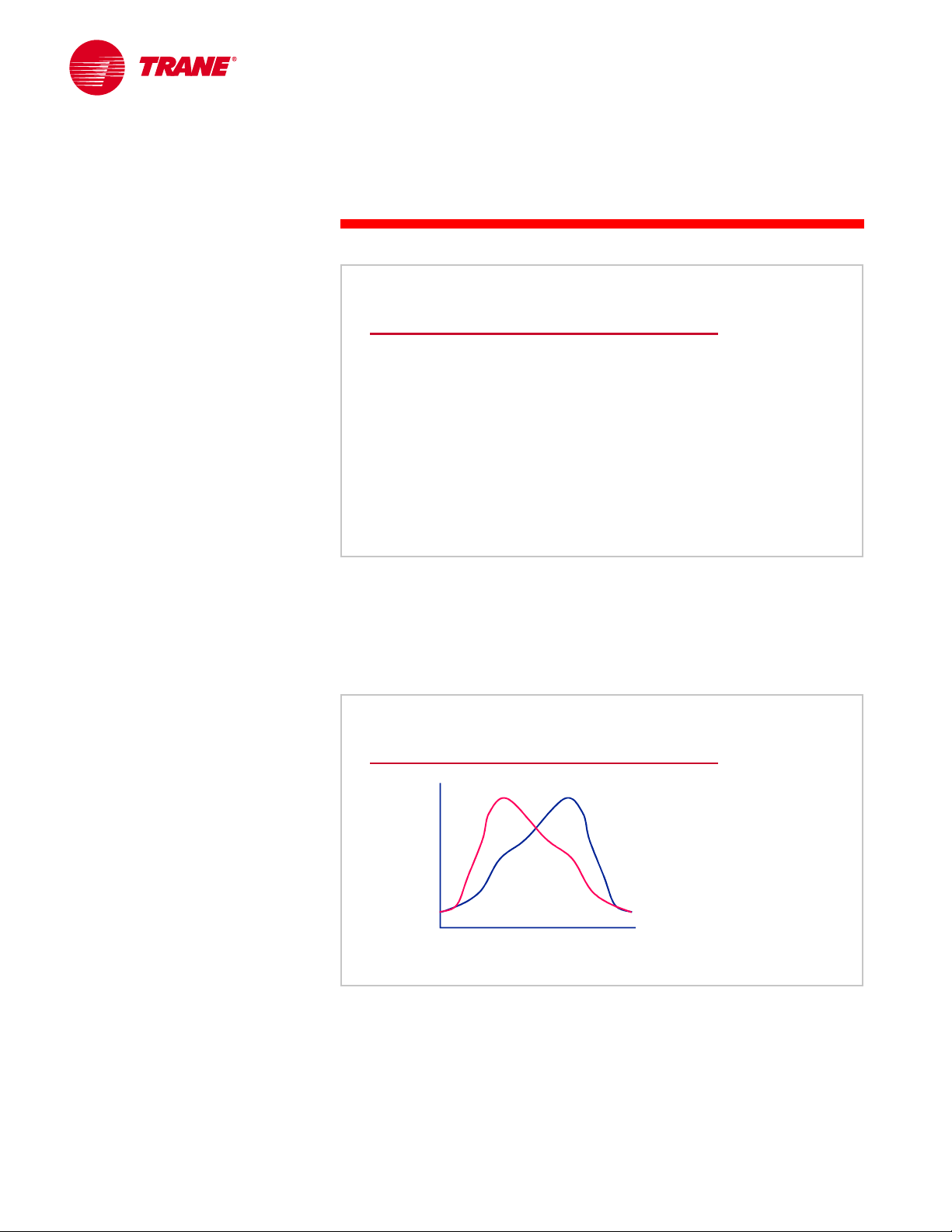
Variable Thermal Load Profiles
east--
facing
east
100
100
75
75
50
50
25
25
percent space loadpercent space load
A key feature of a VAV system is its ability to realize both fan and refrigeration
energy savings at part-load conditions. A building with construction and
utilization characteristics that cause the thermal load profiles of the spaces to
vary throughout the day and year is an excellent application for a VAV system.
facing
space
space
0
0
6126
6126
a.m.
a.m.
noon
noon
west--
west
space
space
p.m.
p.m.
facing
facing
Figure 16
The fact that the west-facing space in this example has a very different load
profile than the east-facing space allows the VAV system to take advantage of
this energy savings at all hours of the day.
10 TRG-TRC014-EN
Page 16
notes
period one
What Is Variable Air Volume?
Independent Space Control
▲ Dedicated terminal units
▲ Dedicated thermostats
Figure 17
Another feature of the VAV system is the ability to efficiently satisfy the comfort
requirements of many different spaces within the building. As we saw from the
comparison of the VAV and terminal reheat systems, the VAV system is the
most efficient at performing this task.
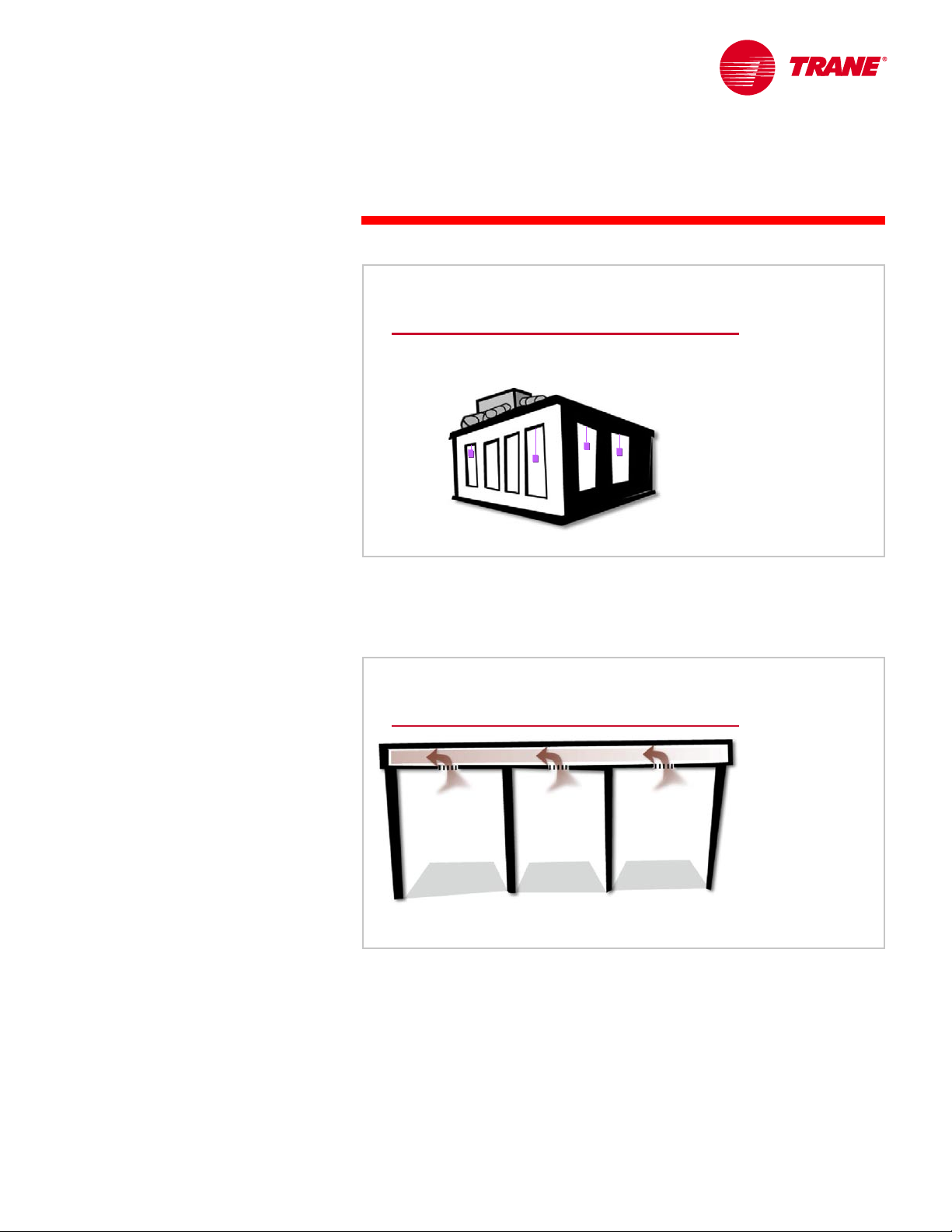
Common Return Air Path
Space 1
Space 1
Because the VAV system uses one central cooling coil and fan to serve many
spaces, the need for a common path to allow the air to return from these spaces
is significant. A return air plenum is commonly used. If return ductwork is
required to connect each conditioned space to the central air handling unit, the
system becomes more difficult to balance and control.
Space 2
Space 2
Space 3
Space 3
Figure 18
TRG-TRC014-EN 11
Page 17
notes
period two
Components of a VAV System
VAV Systems
period two
Components of a VAV System
Figure 19
Next, we will examine the individual components that compose a VAV system.
Components of a VAV System
return air path
return air path
relief
relief
fan
fan
supply
VAV
VAV
box
box
supply
ductwork
ductwork
Figure 20
supply
supply
fan
fan
central
central
air handler
air handler
thermostat
thermostat
A simple VAV system includes the following:
n Central air handler with a variable-volume supply fan, a cooling coil,
possibly a heating coil, controls, filters, a mixing box, and a return or relief
fan
n Supply duct
n VAV terminal unit, or “box,” with a thermostat and supply diffusers for each
independently controlled space
n Thermostat and unit controller for each terminal unit
n Return plenum or duct
The VAV terminal units modulate the airflow supplied to each space.
12 TRG-TRC014-EN
Page 18
notes
period two
Components of a VAV System
VAV Terminal Units
primary
primary
air
air
controller
controller
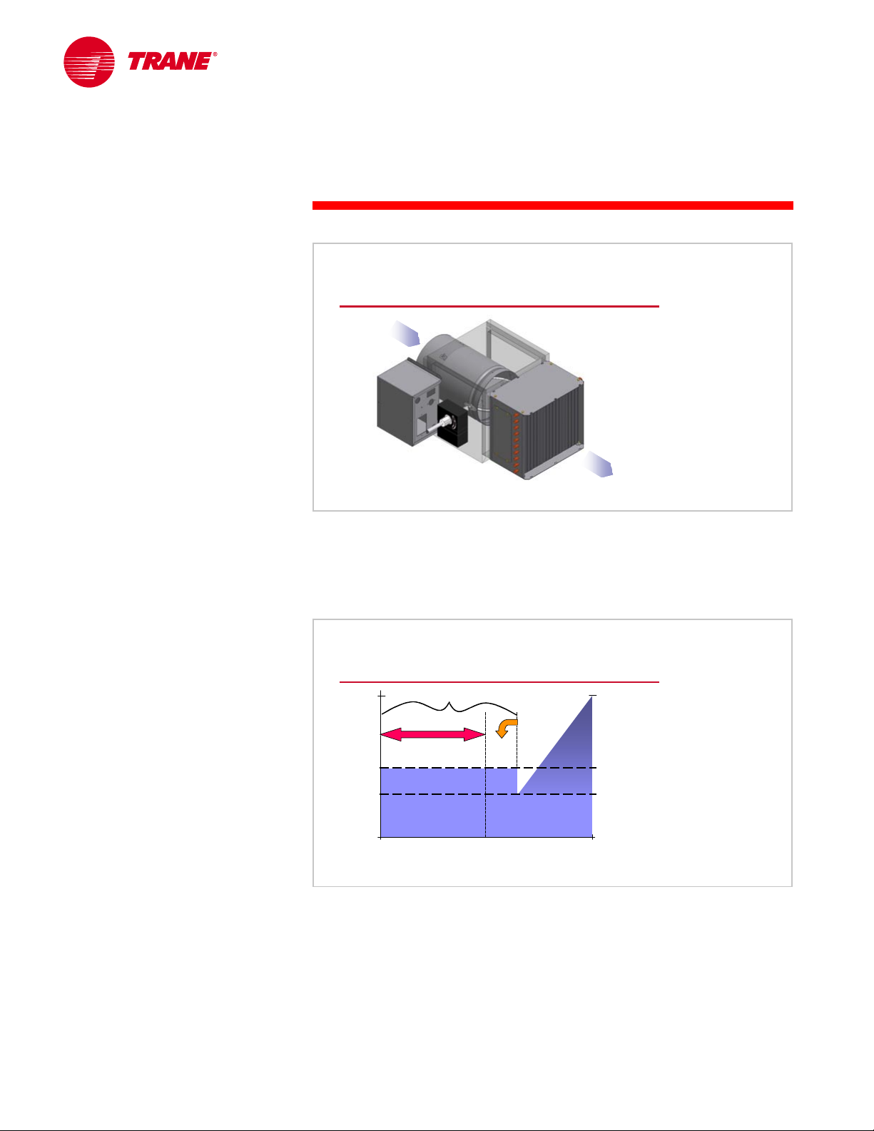
VAV Terminal Units
A VAV terminal unit is a sheet-metal assembly installed upstream of its
respective space diffusers. The unit consists of an air-modulation device,
control hardware and, depending on the system application, possibly a heating
coil, a filter, and a small terminal mixing fan. Modulating the airflow to each
individual space is accomplished using a temperature-controlled mechanical
device that varies the airflow resistance in the supply duct to that space. The
rotating blade damper changes airflow resistance by rotating the damper
into the air stream, restricting the size of the air passage to the space. It is very
cost-effective and flexible. Typically, either a pneumatic or electric controller
can be used to adjust the damper. An understanding of the common VAV
terminal unit types is important to understanding VAV systems.
▲ Heating coil
▲ Filter
▲ Mixing fan
airflow
airflow
modulation
modulation
device
device
supply
supply
air
air
Figure 21
TRG-TRC014-EN 13
Page 19
notes
period two
Components of a VAV System
Single Duct, Cooling Only
primary
primary
air
air
supply
supply
air
air
The simplest of all VAV terminal units is the single-duct, cooling-only
terminal unit. It consists of an airflow modulation device with controls
packaged in a sheet-metal enclosure. The unit can only modulate the primary
airflow to the space. The primary air is supplied by a single, central air handler.
This VAV terminal unit is typically used for those zones that require year-round
cooling, like the interior zones of a building. It is the most common and basic
type of single-duct VAV terminal unit.
Figure 22
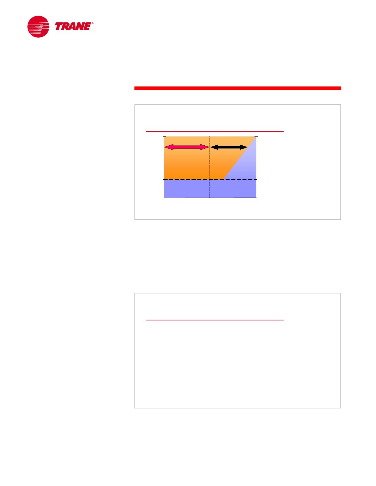
Single Duct, Cooling Only
remote source of heat
100%
% airflow to space
0%
heating load
remote source of heat
design
heating tempering
heating
space load
tempering
primary air
primary air
This graph indicates how the air supplied to the space by the terminal unit
varies as the space loads change. The vertical axis indicates the total airflow
supplied to the space. The horizontal axis indicates the space load.
The supply airflow to the space is reduced as the cooling load in the space
decreases. Responding to the space thermostat, the primary airflow is
modulated between maximum and minimum settings. The maximum setting is
14 TRG-TRC014-EN
maximum
primary
airflow
minimum
primary
airflow
design
cooling load
Figure 23
Page 20
period two
Components of a VAV System
notes
determined by the design cooling load of the space and the minimum setting is
normally determined by the space ventilation requirement or minimum airflow
for proper diffuser selection.
Most cooling-only units are applied to spaces that have no need for heat. These
units would operate in the region on the right-hand portion of this chart,
modulating between design and minimum primary airflow. When cooling-only
units are applied to spaces that do have heating requirements, the heat is
provided by a remote source such as finned radiation along the wall. In these
spaces, when the cooling load drops below the minimum airflow setting for the
unit, overcooling the space, the remote heat source activates. When space
heating is required, the remote heat source satisfies the space heating load.
Most terminal unit controllers provide an output signal to control this remote
source of heat.
Space Heating with a VAV System
terminal
terminal
mixing fan
mixing fan
plenum air
plenum air
remote
heating
heating
coil
coil
In addition to controlling this remote source of heat (perimeter baseboard
radiation, in this example), single-duct VAV terminal units can directly provide
heat to a space. This can be accomplished by adding a heating coil to each
cooling-only unit or by mixing the primary air with warm plenum air before it is
delivered to the space.
TRG-TRC014-EN 15
remote
heat source
heat source
Figure 24
Page 21
notes
period two
Components of a VAV System
VAV Reheat
primary
primary
air
air
terminal
terminal
heating coil
heating coil
supply
supply
air
air
VAV r e heat terminal units provide supply-air tempering or space heating by
reheating the cool primary air. This is accomplished by adding an electric, or
hot-water, heating coil to the discharge of a cooling-only unit.
Figure 25
The VAV reheat terminal unit is typically used for those zones that require
seasonal cooling and heating, such as exterior zones of a building.
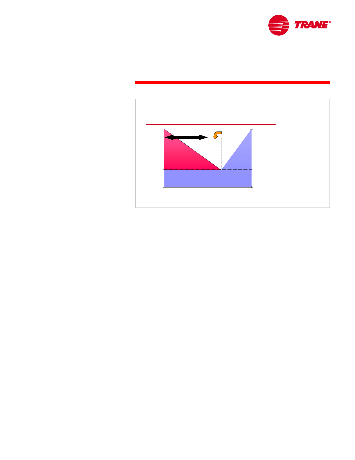
VAV Reheat
heating coil active
design
heating coil active
heating tempering
heating
space load
tempering
primary air
primary air
100%
% airflow to space
0%
heating load
In the cooling mode, the unit is controlled in the same manner as the coolingonly unit. The supply airflow is reduced as the cooling load in the space
decreases. When the space cooling load drops below the minimum primary
airflow setting for the unit, overcooling the space, the heating coil warms
(tempers) the primary air to balance the low space cooling load. When space
heating is required, the heating coil further warms the primary air to satisfy the
space heating load.
maximum
primary
airflow
minimum
heating
airflow
minimum
cooling
airflow
design
cooling load
Figure 26
16 TRG-TRC014-EN
Page 22
period two
Components of a VAV System
notes
During the heating mode, the primary airflow must often be greater than the
minimum setting of the unit for the cooling mode. When warm, buoyant air is
supplied from the ceiling, a certain velocity is required to effectively deliver
it down to the occupied portion of the space. Increased airflow may also be
needed to meet the minimum requirement for proper operation of the
heating coil.
VAV reheat is more efficient than the constant-volume reheat system discussed
earlier because heat is provided at reduced airflow and only when required.
Fan-Powered Terminal Units
warm
warm
plenum air
plenum air
cool
cool
primary air
primary air
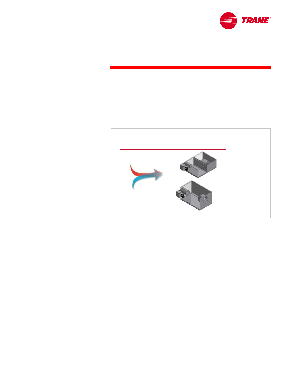
parallel
series
Figure 27
Another method that a single-duct VAV terminal unit can employ to heat a
space is to mix warm plenum air with cool primary air. Because this method
uses a small fan to draw warm air from the plenum and mix it with the primary
air, they are called fan-powered terminal units.
They come in two configurations, parallel and series.
TRG-TRC014-EN 17
Page 23
notes
period two
Components of a VAV System
Parallel, Fan-Powered
plenum
plenum
air
air
primary
primary
air
air
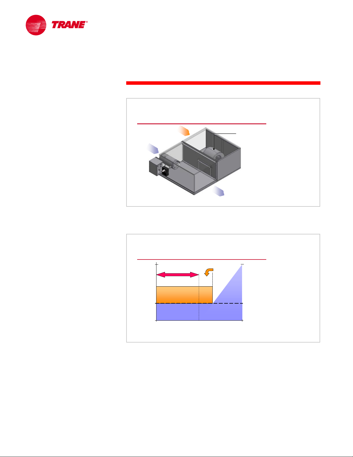
A parallel, fan-powered terminal unit consists of a primary airflow
modulation device and a small, integral, constant-volume fan packaged to
provide parallel airflow paths.
supply
supply
air
air
terminal
terminal
mixing fan
mixing fan
Figure 28
Parallel, Fan-Powered
design
cooling load
maximum
primary
airflow
minimum
primary
airflow
Figure 29
100%
% airflow to space
0%
design
heating load
heating
heating
plenum air
plenum air
space load
tempering
tempering
primary air
primary air
In the cooling mode, the unit is controlled in the same manner as the coolingonly unit. Primary airflow is reduced as the cooling load in the space decreases.
When the space cooling load drops below the minimum primary airflow setting
for the unit, overcooling the space, the small fan activates to mix warm plenum
air with the cool primary air. This increases the total airflow to the space and
creates a warmer supply air condition. If additional heating is required, with the
terminal fan on, a heating coil can be used to further warm the supply air.
Operating the fan is a form of energy recovery. It tempers the supply air with
heat from the building and lights carried by the return air, rather than with
“new” energy, thus delaying the start of the heating coil.
18 TRG-TRC014-EN
Page 24
period two
Components of a VAV System
notes
When in cooling mode, the supply airflow to the space equals the primary
airflow. When in tempering and heating modes, the space receives a constant
supply airflow equal to the minimum primary airflow plus the plenum airflow
delivered by the terminal fan. Usually the primary airflow is not allowed to shut
off completely because of the space requirement for ventilation air.
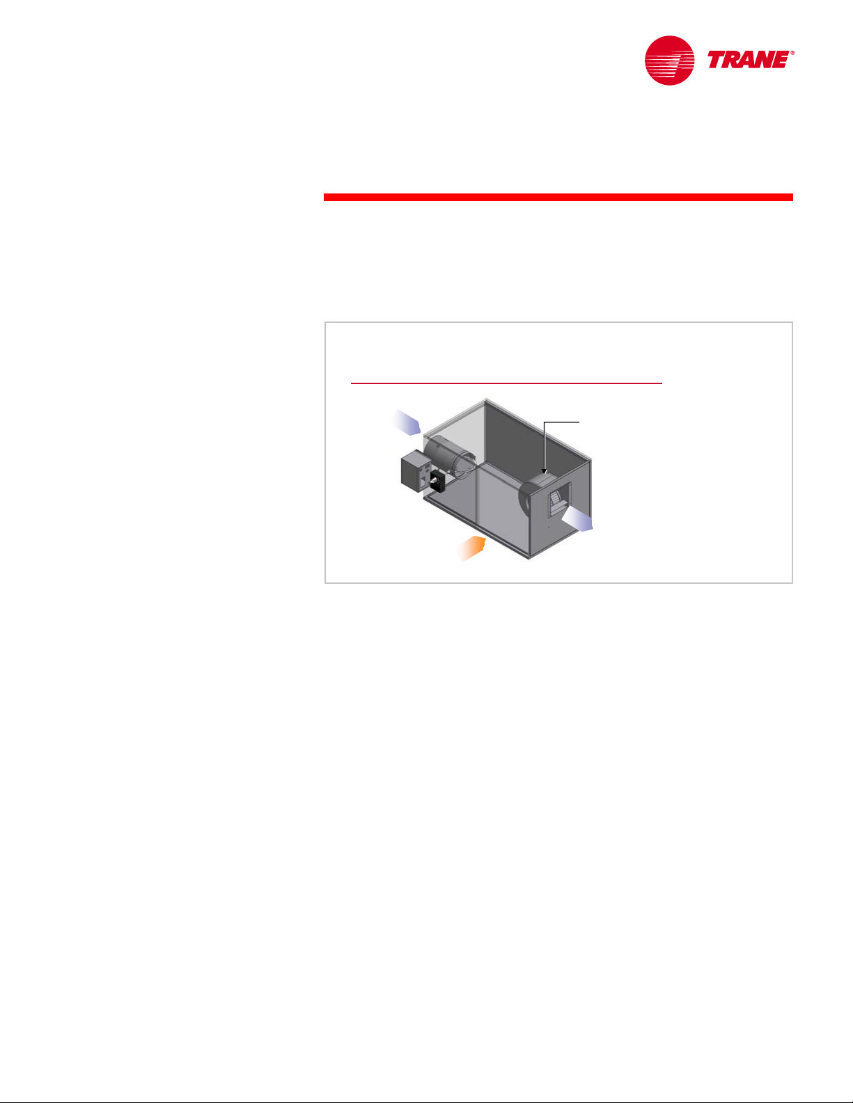
Series, Fan-Powered
primary
primary
air
air
plenum
plenum
air
air
A series, fan-powered terminal unit consists of an airflow modulation device
and a small, constant-volume fan, packaged so that their airflow paths are in
series. The terminal unit fan operates continuously whenever the space is
occupied. The fan draws air from either the primary air stream or the plenum,
based on the thermostat in the space. This results in a constant volume of
supply air delivered to the space at all times.
terminal
terminal
mixing fan
mixing fan
supply
supply
air
air
Figure 30
TRG-TRC014-EN 19
Page 25
notes
period two
Components of a VAV System
Series, Fan-Powered
design
cooling load
maximum
primary
airflow
minimum
primary
airflow
Figure 31
100%
tempering
tempering
primary air
primary air
% airflow to space
0%
design
heating load
heating
heating
plenum air
plenum air
space load
In the cooling mode, the primary airflow is reduced as the cooling load in the
space decreases. The total supply airflow to the space remains constant, a
combination of cool primary air and warm plenum air. If the space cooling load
drops below the minimum primary airflow setting for the unit, or if space
heating is required, a heating coil can be used to further warm the supply air to
the space.
The maximum airflow for the airflow modulation device typically equals the
terminal fan airflow. This means that at the design cooling load, primary airflow
equals supply airflow.
Parallel Versus Series Fan-Powered
▲ Constant airflow to the space
▲ Acoustics
▲ Fan energy consumption
Figure 32
Series, fan-powered units are generally considered the premium VAV system
because while the central system operates as a variable-volume system, the
spaces receive constant supply airflow. Increased air motion in the space
improves comfort at all load conditions and the constant airflow simplifies
diffuser selection.
20 TRG-TRC014-EN
Page 26
period two
Components of a VAV System
notes
Most designers also believe that series units offer improved acoustical
conditions in the space. The constant sound of the series unit, with the fan
operating whenever the space is occupied, is generally preferred to the on-off
sound generated by the cycling fan in the parallel unit.
However, because the fan runs continuously whenever the space is occupied, a
series fan-powered unit consumes more energy than a parallel fan-powered
unit. The development of high-efficiency motors has lessoned the energy
consumption difference. The fan in a series fan-powered unit also costs more
than an equivalent parallel fan-powered unit because it generally requires a
larger terminal fan.
Fan-powered terminal units without a heating coil are typically used to provide
tempering for those zones that require year-round cooling and have relatively
high minimum airflow settings, such as the densely occupied interior zones of a
building (i.e., a conference room). A fan-powered terminal unit with a heating
coil is typically used for spaces that require seasonal cooling and heating, such
as the exterior zones of a building. Units with heating coils are the most
common of the fan-powered terminal units.
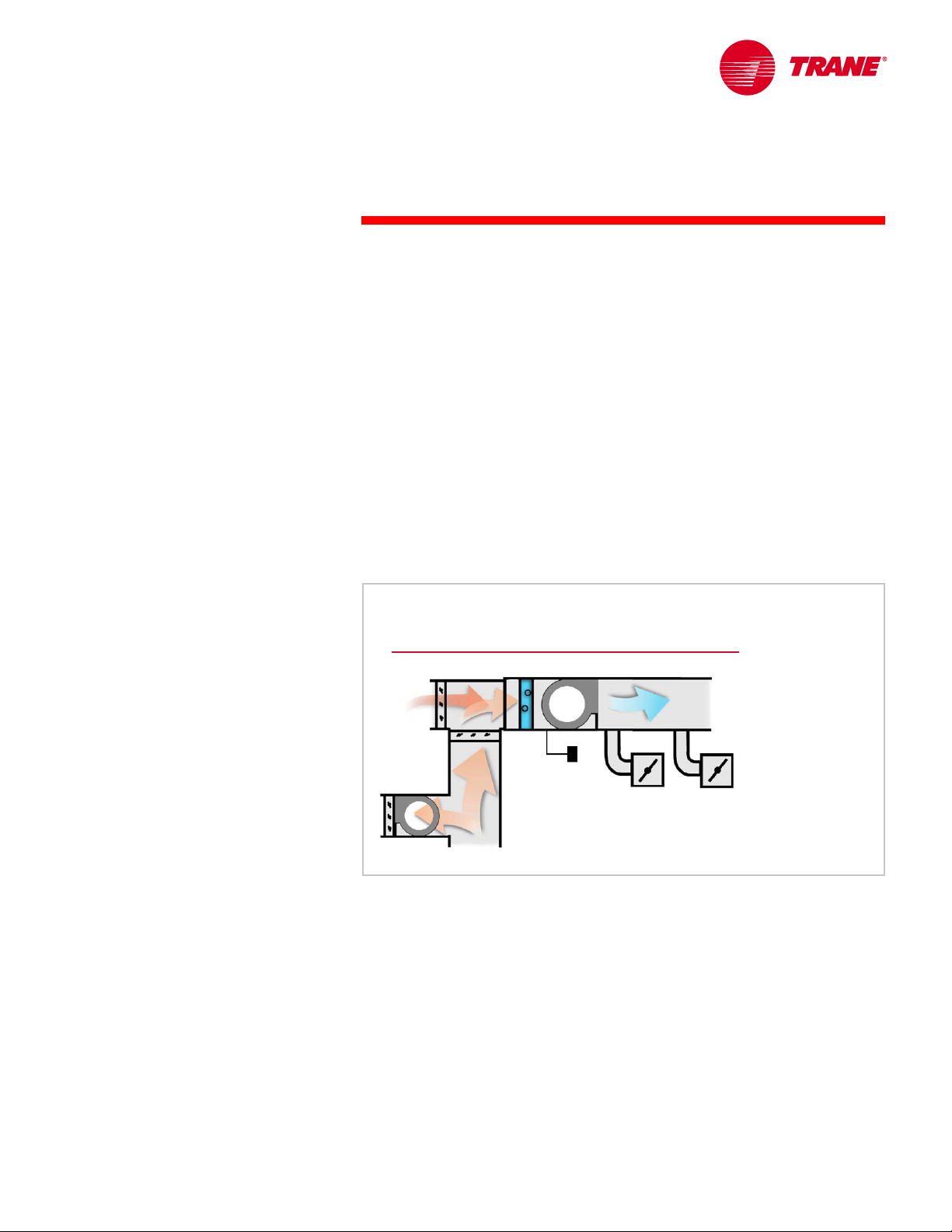
Single-Duct VAV Systems
central air handler
central air handler
55°F
90°F
90°F
[32.2°C]
[32.2°C]
OA
PA
55°F
[12.8°C]
[12.8°C]
VSD
VSD
single--
EA
RA
80°F
80°F
[26.7°C]
[26.7°C]
duct
single
duct
VAV terminal units
VAV terminal units
Figure 33
The types of terminal units discussed so far are used in single-duct VAV
systems. Single-duct VAV systems use a central return-air path that allows the
air from the spaces to come back to the air handler. At the air handler, a portion
of this return air is recirculated and mixed with outdoor air (introduced for
space ventilation purposes). This mixture of outdoor and recirculated return air,
or primary air, is then conditioned and delivered to the VAV terminal units
through the supply duct system.
The remainder of the return air is exhausted from the building.
TRG-TRC014-EN 21
Page 27
notes
period two
Components of a VAV System
Dual-Duct
warm
warm
primary air
primary air
cool
cool
primary air
primary air
supply
supply
air
air
A dual-duct terminal unit consists of two airflow modulation devices with
controls packaged in a sheet-metal enclosure. One controls the cool primary air
and the other controls the warm primary air. Depending on the method of
control, these two air streams may mix in the dual-duct unit before proceeding
downstream to the space.
Figure 34
This VAV terminal unit is intended for zones that require seasonal cooling and
heating, typically the exterior zones of a building. It is seldom used because of
the high first cost incurred to provide two duct systems.
A dual-duct terminal unit can be controlled to provide either a variable volume
or a constant volume of supply air to the space.
22 TRG-TRC014-EN
Page 28
notes
period two
Components of a VAV System
Variable Air Volume to the Space
100%
% airflow to space
0%
design
heating load
As before, this graph indicates how the air supplied to the space by the terminal
unit varies as the space loads change. The vertical axis indicates the total
airflow (cool primary air plus warm primary air) supplied to the space. The
horizontal axis indicates the space load.
To deliver a variable volume of supply air to the space in a two-fan, dual-duct
system in the cooling mode, the dual-duct unit is controlled in the same manner
as the cooling-only unit. The cool primary airflow is reduced as the cooling load
in the space decreases. When the space cooling load drops below the minimum
cool primary airflow setting for the unit, overcooling the space, the second
modulating device begins to open. This allows the warm primary air to mix
with the cool primary air and provide warmer supply air to the space.
heating
heating
warm
warm
primary air
primary air
cool
cool
space load
tempering
tempering
primary air
primary air
maximum
primary
airflow
minimum
primary
airflow
design
cooling load
Figure 35
As the cooling load decreases further and the space requires heating, more
warm primary air is mixed with the minimum amount of cool primary air.
TRG-TRC014-EN 23
Page 29

notes
period two
Components of a VAV System
Constant Air Volume to the Space
minimum
primary
airflow
design
cooling load
maximum
primary
airflow
Figure 36
100%
warm
warm
primary air
primary air
% airflow to space
0%
design
heating load
cool
cool
space load
primary air
primary air
To deliver a constant volume of supply air to the space in a two-fan, dual-duct
system as the cooling load in the space decreases, the amount of cool primary
air is reduced and the amount of warm primary air is increased, maintaining a
constant total supply airflow to the space.
Because of this constant airflow to the space, no fan energy savings is realized
at part-load conditions.
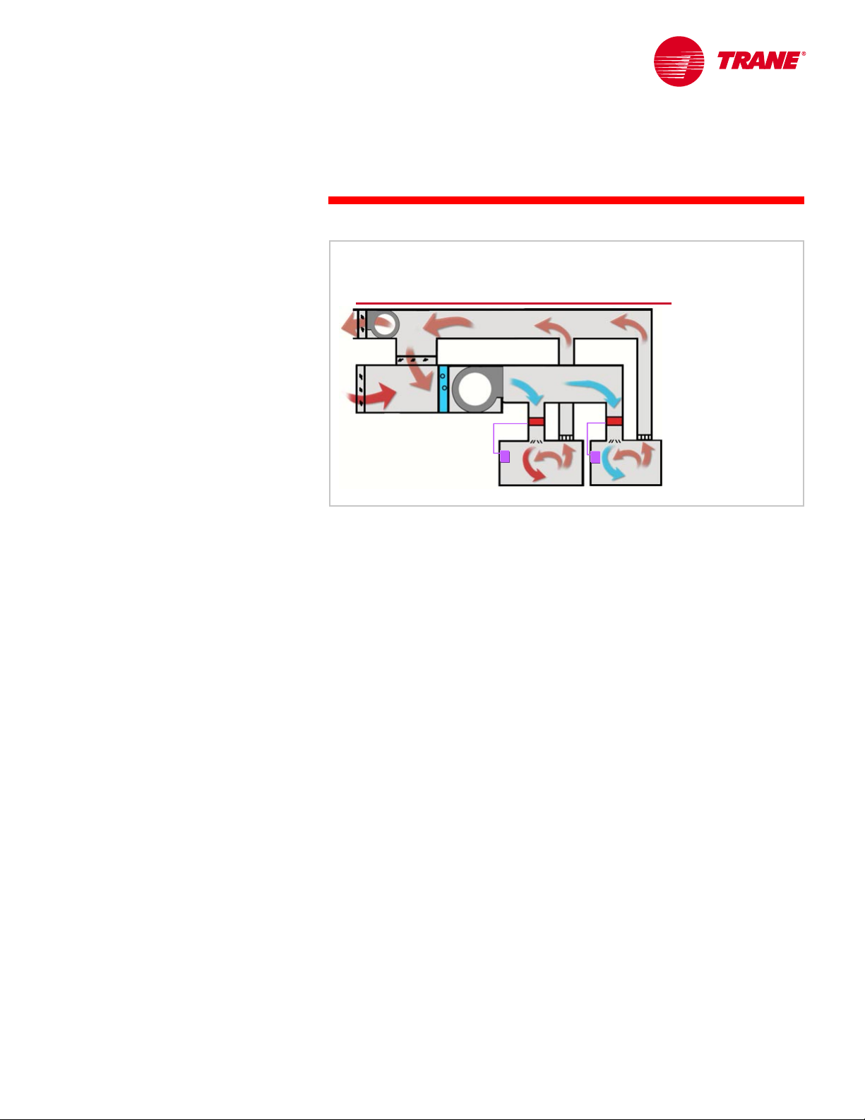
Single-Fan, Dual-Duct VAV System
cooling
cooling
coil
coil
heating
heating
coil
coil
EA
OA
40°F
40°F
[4.4°C]
[4.4°C]
55°F
55°F
[12.8°C]
[12.8°C]
RA
75°F
75°F
[23.9°C]
[23.9°C]
central air handler
central air handler
VSD
VSD
Dual-duct VAV systems also have a central return-air path that allows air from
the spaces to come back to the air handler. Dual-duct systems may, however,
have either one or two central air handlers.
At the single air handler, a portion of the return air is recirculated and mixed
with outdoor air. This mixture of outdoor and recirculated return air is then
diverted through either the cooling coil or the heating coil and delivered down
24 TRG-TRC014-EN
55°F
55°F
105°F
105°F
[12.8°C]
[12.8°C]
[40.6°C]
[40.6°C]
dual--
duct
dual
duct
VAV
VAV
terminal
terminal
units
units
Figure 37
Page 30

period two
Components of a VAV System
notes
the respective duct system to the modulation devices in the dual-duct VAV
terminal units.
While this single-fan configuration requires only one air handler, it is very
complicated to control efficiently. In this example, the economizer is controlling
the mixed air temperature to 55°F [12.8°C], thus saving the energy to operate
the cooling coil. However, the heating coil must warm the air from 55°F [12.8°C]
to the 105°F [40.6°C] primary air temperature. If the economizer was not
activated, the mixed air temperature would be 75°F [23.9°C], requiring less
heating energy, but now the cooling coil must operate. Optimizing the energy
use of a single-fan, dual-duct system requires a very complicated control
system and does not operate as efficiently as a two-fan, dual-duct system.
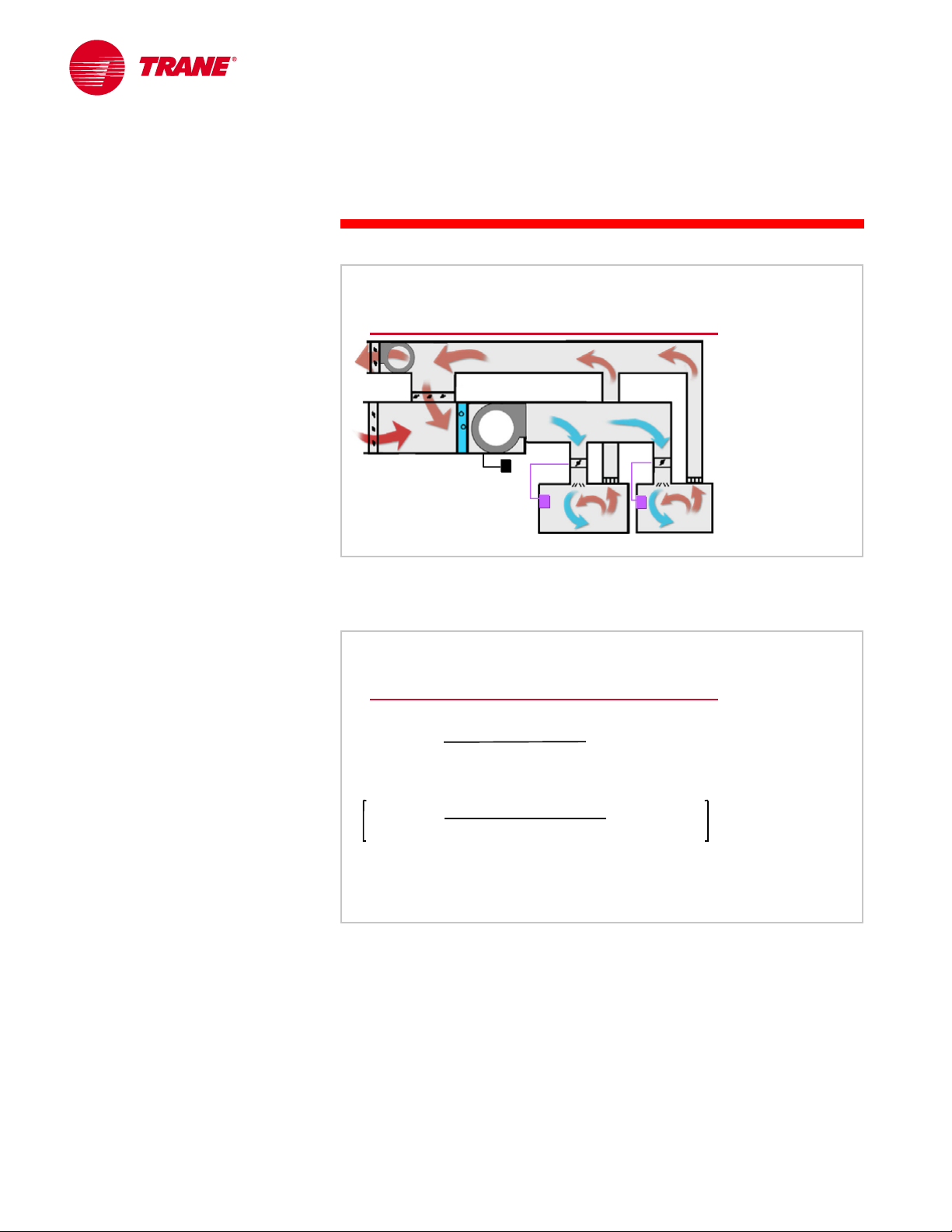
Two-Fan, Dual-Duct VAV System
OA
40°F
40°F
[4.4°C]
[4.4°C]
EA
55°F
55°F
[12.8°C]
[12.8°C]
RA
cooling
cooling
air handler
air handler
heating
heating
air handler
air handler
PA
PA
55°F
55°F
105°F
105°F
[12.8°C]
[12.8°C]
[40.6°C]
[40.6°C]
dual--
duct
dual
duct
VAV
VAV
terminal
terminal
units
units
75°F
75°F
[23.9°C]
[23.9°C]
Figure 38
Dual-duct systems can be very energy efficient when the mixing of cool and
heated air is avoided and two supply fans are used – one for heating, the other
for cooling. This arrangement eliminates the inefficient or wasteful reheating of
mixed air in a single-fan, dual-duct system and allows an airside economizer to
provide cool primary air whenever possible.
At the cooling air handler, a portion of the return air is recirculated and mixed
with outdoor air (introduced for space ventilation purposes). This mixture of
outdoor and recirculated return air is then cooled and delivered as cool primary
air to one of the modulation devices in the dual-duct VAV terminal units through
the cooling supply duct system.
Air delivered by the heating air handler contains only recirculated air, no
outdoor air. This air is heated and delivered as warm primary airflow to the
other modulation device in the dual-duct VAV terminal units through the
heating supply duct system.
The remainder of the return air is exhausted from the building. The cooling air
modulation device typically has a minimum setting to accommodate the
ventilation requirements of the space.
TRG-TRC014-EN 25
Page 31

notes
period two
Components of a VAV System
VAV Terminal Unit Controls
Figure 39
VAV Terminal Unit Controls
Next we will explore the control of VAV terminal units. Before discussing the
commonly-available control technologies, it is important to first understand a
fundamental control concept: pressure-dependent versus pressure-
independent control.
Upstream Pressure Affects Airflow
0.70 in. H
O
0.70 in. H
static pressure
static pressure
in supply duct
in supply duct
0.80 in. H
0.80 in. H
static pressure
static pressure
in supply duct
in supply duct
The modulating device in a VAV terminal unit changes the air resistance of the
supply duct path to the space. As terminal units modulate, the static pressure
within the duct system changes. The airflow that passes through the terminal
unit depends not only on the position of the modulation device but also on the
static pressure at the inlet. With the modulation device in a fixed position, a
higher static pressure in the upstream duct will “push” more air through the
terminal unit. Because the inlet static pressure constantly changes due to the
modulation of the terminal units in the system and the resulting variation of
26 TRG-TRC014-EN
2
[175 Pa]
[175 Pa]
2
[200 Pa]
[200 Pa]
O
2
VAV terminal unit
VAV terminal unit
(identical damper positions)
(identical damper positions)
O
O
2
1000
1000
[0.47 m
[0.47 m
1300
1300
[0.61 m
[0.61 m
cfm
cfm
3
3
cfm
cfm
3
3
/s]
/s]
/s]
/s]
Figure 40
Page 32

period two
Components of a VAV System
notes
duct static pressure, airflow to the space can vary even when the immediate
modulation device does not change position.
Pressure-Dependent Control
▲ Space sensor controls position of the
modulating device
▲ Airflow to space depends on SP in upstream
duct system
Pressure-Independent Control
▲ Space sensor controls desired airflow
▲ Airflow to space is controlled directly,
independent
A pressure-dependent VAV control scheme uses the space temperature
sensor to directly control the position of the modulating device. The actual
airflow delivered to the space is a by-product of this position and depends on
the duct system static pressure at the inlet of the terminal unit. Although the
space temperature sensor will continually correct the position of the
modulating device, the response can be sluggish and cause unacceptable
temperature variations within the space.
of SP in upstream duct system
Figure 41
In contrast, a pressure-independent VAV control scheme directly controls the
actual volume of primary air that flows to the space. An airflow-measuring
device on the terminal unit makes this possible. The position of the modulation
device is not directly controlled and is basically a by-product of regulating the
airflow through the unit. Because the airflow delivered to the space is directly
controlled, it is independent of inlet static pressure.
Pressure-independent control increases the stability of airflow control, and
allows minimum and maximum airflow settings to become actual airflows
rather than physical positions of the modulation device. It is clearly the most
popular form of VAV terminal unit control.
TRG-TRC014-EN 27
Page 33

notes
period two
Components of a VAV System
Primary Airflow Measurement
airflow
airflow
airflow sensor
airflow sensor
measured
measured
pressure
pressure
difference
difference
Figure 42
Accurate measurement of primary airflow is required to enable pressureindependent control. Most terminal units accomplish this with a multipoint
airflow sensor mounted on the inlet.
This sensor measures a pressure difference between the ports that face the
airflow and the ports that face downstream. The result is a pressure difference
signal that relates to the airflow rate passing through the modulation device.
Terminal-Unit Control Technologies
▲ Pneumatic control
▲ Electronic control
▲ Direct digital control (DDC)
Figure 43
Now that we understand pressure-dependent versus pressure-independent
control, we will look at the technologies available to perform this control.
Three control technologies are generally available in VAV terminal units. They
are pneumatic, electronic, and direct digital control (DDC).
28 TRG-TRC014-EN
Page 34

notes
period two
Components of a VAV System
Pneumatic Control
▲ Pneumatic Volume Regulator (PVR) provides
pressure-independent control
▲ Pneumatic thermostat directly controls terminal-
unit fan and heat source
▲ Minimum and maximum airflow settings
adjusted physically on PVR
▲ Compressed air operates modulation device,
PVR, and space thermostat
Figure 44
A pneumatically-controlled terminal unit has an airflow-modulation device
operated by a pneumatic actuator consisting of an inflatable bladder and a
return spring. The return spring positions the damper to a “normal” state (the
position it assumes with no pressure applied in the bladder), typically fully
open. If the pneumatic pressure increases in the bladder, the return spring
compresses and the modulation device begins to close. If pneumatic pressure
is allowed to bleed from the bladder, the force of the return spring expanding
begins to open the modulation device.
A pneumatic volume regulator (PVR) provides pressure-independent control of
the VAV terminal unit. The PVR is connected to the airflow-measurement device
and the pneumatic space thermostat. The PVR directs the actuator to position
the modulation device to deliver the required airflow to the space. The
pneumatic thermostat signal is used to reset this airflow set point, and it
directly controls the terminal fan and heat source.
Minimum and maximum airflow settings are physically adjusted on the PVR.
Compressed air is required to operate the modulation device and to power the
PVR and the space thermostat.
TRG-TRC014-EN 29
Page 35

notes
period two
Components of a VAV System
Electronic Control
▲ Electronic pressure transducer provides
pressure-independent control
▲ Electronic controller positions modulation
device, controls terminal fan and heat source
▲ Minimum and maximum airflow settings
adjusted physically on electronic controller
▲ Electric power supply operates modulation
device and electronic controller
Figure 45
An electronically-controlled terminal unit has an airflow-modulation device
operated by an electronic actuator that can drive the modulation device open or
closed. Electrically-actuated modulation devices typically do not have a spring
to return them to a “normal” state if power is lost – they stop at the position
they held when the power loss occurred. The actuator motor is operated with
three wires: “common,” “drive open,” and “drive closed.” To drive the device
open, the electronic controller applies 24 volts between the “common” and
“drive open” wire. To drive the device closed, it applies 24 volts between the
“common” and “drive closed” wire. To stop the actuator, no voltage is applied.
Actuator drive time is determined by the design of the electric motors and
gears, but is typically between one and six minutes.
An electronic pressure transducer enables pressure-independent control of the
VAV terminal unit. The pressure transducer is pneumatically connected to the
airflow sensor for airflow measurement and is wired to the electronic controller
along with the space temperature sensor. The electronic controller positions the
modulation device to deliver the required airflow to the space, and operates the
fan and heat source.
Minimum and maximum airflow settings are physically adjusted on the
electronic controller. A 24-volt power supply is required to power the unit
actuator and controls.
30 TRG-TRC014-EN
Page 36

notes
period two
Components of a VAV System
Direct Digital Control (DDC)
central air handler
central air handler
DDC/VAV
DDC/VAV
terminal units
communicating
communicating
building automation
building automation
system (BAS)
system (BAS)
A digitally-controlled terminal unit has an airflow-modulation device
operated with an electric actuator in the same manner as the electronic control
option. The key difference between electronic control and direct digital control
is that the digital controller uses a microprocessor as the intelligence behind
the control of the terminal unit. This microprocessor enables digital
communication between the unit controller and the central building automation
system.
The result is a system that can be monitored from a central point, offers control
flexibility, and enables system-optimized control strategies. Buildings can be
controlled more intelligently because the data (such as airflow, damper
position, fan, and heat status) is available to perform complex system-control
strategies and diagnostics from a central monitoring station.
terminal units
Figure 46
TRG-TRC014-EN 31
Page 37

notes
period two
Components of a VAV System
Direct Digital Control (DDC)
▲ Electronic pressure transducer provides
pressure-independent control
▲ Digital controller positions modulation device,
controls terminal fan and heat source
▲ Minimum and maximum airflow settings
adjusted through communication link
▲ Electric power supply operates modulation
device and electronic controller
Figure 47
Similar to electronic control, an electronic pressure transducer enables
pressure-independent control of the VAV terminal unit. The digital controller
positions the modulation device and operates the fan and the heat source.
Minimum and maximum airflow settings are adjusted through a
communication link to the digital controller. A 24-volt power supply is required
to power the unit actuator and controls.
32 TRG-TRC014-EN
Page 38

notes
period two
Components of a VAV System
Diffusers
flexible
flexible
duct
duct
diffuser
sheet metal
sheet metal
supply duct
supply duct
VAV
primary air
primary air
Diffusers
Each VAV terminal unit is commonly connected to a downstream, sheet-metal
duct that is then connected to the remotely-located diffusers by flexible ducts.
Diffusers distribute the supply air effectively to the conditioned space.
Proper air diffusion is an important comfort consideration, especially in VAV
systems. Because VAV systems require the diffuser to provide proper space air
mixing over a wide range of airflows, diffusers that are specifically intended for
use in VAV applications should be used to prevent cold air “dumping” at low
airflow rates.
VAV
terminal unit
terminal unit
diffuser
Figure 48
TRG-TRC014-EN 33
Page 39

notes
period two
Components of a VAV System
Linear Slot Diffuser
linear
linear
slot
slot
diffuser
diffuser
Coanda
effect
55°F
[12.8°C]
[12.8°C]
55°F
air from
air from
space
space
Linear slot diffusers are generally preferred for VAV air distribution. They use a
principle known as the Coanda effect to distribute air to the conditioned
space. The Coanda effect occurs when air is discharged at a relatively high
velocity along the surface of the ceiling. This creates an area of low pressure
that causes the supply air to hug the ceiling. As it travels along the ceiling, air
from the space is drawn into, and mixed with, the supply air stream. When the
air settles to the occupied levels of the space, it has reached an average
temperature.
5 ft
[1.5 m]
[1.5 m]
5 ft
supply air
supply air
supply duct
supply duct
Figure 49
The design of linear slot diffusers allows them to effectively distribute air over a
wide range of airflows, making them the preferred diffuser for VAV systems.
They also offer acoustical benefits over other types of diffusers.
Proper selection and placement of linear slot diffusers generates air movement
throughout the space, eliminating areas of stagnant and stratified air.
For applications with special air-coverage requirements, such as the
“blanketing” of an outside wall or window area, one-way discharge diffusers
are commonly used. Such coverage is particularly useful for overcoming the
downdraft problems that can occur when large volumes of heated air are
distributed through ceiling diffusers.
34 TRG-TRC014-EN
Page 40

notes
period two
Components of a VAV System
Ceiling–Diffuser Compatibility
hanger wire
hanger wire
ceiling tile
ceiling tile
cross T
cross T
structural T
structural T
Figure 50
Because variable-air-volume systems are installed in, and distribute air along
the surfaces of, ceilings, it is essential that the diffusers be compatible with the
ceiling design.
The T-bar ceiling is possibly the most popular design. It is constructed of a grid
of inverted T-shaped members suspended by wires from the floor or roof
structure above. Cross members added to the load bearing T-bars generate a
symmetrical ceiling pattern. Finally, ceiling tiles are laid in place and supported
by this grid.
TRG-TRC014-EN 35
Page 41

notes
period two
Components of a VAV System
Ceiling–Diffuser Compatibility
cross T
cross T
air slot flange
air slot flange
mounting feet
mounting feet
cross T
cross T
structural T
structural T
The linear slot diffuser is placed on the structural T-bars with the mounting feet
resting on the flanges. The cross member fits in a slot in the diffuser air
opening, aligning the unit with the ceiling tile pattern.
air slot
air slot
ceiling
ceiling
tile
tile
Figure 51
The weight of the linear slot diffuser is partially carried by the T-bar structure,
but should also be augmented by hanger wires to ensure a vertical orientation
and provide additional weight support.
After the diffuser is mounted, ceiling tiles are trimmed and laid in place,
completing the job.
36 TRG-TRC014-EN
Page 42

notes
period two
Components of a VAV System
Supply Duct System
central
central
air handler
air handler
diffuser
diffuser
flexible
flexible
duct
duct
sheet metal
sheet metal
supply duct
supply duct
VAV
VAV
terminal
terminal
unit
unit
Supply Duct System
The supply duct system transports the primary air from the air handler to the
VAV terminal units and then on to the space diffusers. A successful design
achieves the following:
n Minimizes the static pressure and associated power requirements of the
supply fan
n Minimizes the installed cost without sacrificing system efficiency
n Supplies air to each VAV terminal unit without excessive noise
n Accommodates space limitations without excessive pressure drop
n Minimizes design time
Figure 52
TRG-TRC014-EN 37
Page 43

notes
period two
Components of a VAV System
Duct Design
▲ Equal friction method
◆ Equal static pressure drop per unit length of duct
◆ Design can be performed by hand
▲ Static regain method
◆ Relatively constant static pressure throughout system
◆ Desirable for VAV system duct design
◆ Design often requires a computer program
Figure 53
Designers commonly use two methods to engineer the supply duct system:
n Equal friction
n Static regain
Equal friction duct systems are designed for an equal static-pressure drop per
foot of duct. This results in a static pressure that is very high near the fan, and
which steadily decreases until it is very low near the far terminal units. Equal
friction duct systems can be easily designed by hand.
Static regain duct systems strive to maintain a fairly consistent static pressure
throughout the entire duct. Therefore, for VAV systems, the static regain
method is recommended for sizing the supply ducts upstream of the terminal
units. This relatively constant static pressure at the terminal unit inlet allows for
improved selection and control. The design of a static regain duct system often
requires the use of a computer program.
38 TRG-TRC014-EN
Page 44

notes
period two
Components of a VAV System
Duct Design Recommendations
▲ Keep as simple and symmetrical as possible
▲ Locate main runs, branch runs, and terminal units
above hallways or unoccupied spaces
▲ Minimize use of flexible ductwork upstream of
terminal units
▲ Use duct lining or a duct silencer in first duct
section to attenuate supply fan noise
▲ Place balancing dampers upstream of diffusers in
all noncritical branches
▲ Reducing transitions should be several duct
diameters upstream of terminal units
Figure 54
Other publications contain more complete details related to duct design, but
here are a few general recommendations:
n Keep the duct layout as simple and symmetrical as possible
n Place main duct runs and, when possible, branch runs and terminal units,
above hallways and other “unoccupied” areas to ease installation and
maintenance and to help attenuate the sound radiated to the occupied
spaces
n Limit the use of flexible ductwork upstream of the terminal unit
n Apply a duct lining or duct silencer to the first section of the duct system in
order to attenuate supply fan noise
n Add balancing dampers upstream of diffusers in all noncritical branches
n If needed, reducing transitions should be located several duct diameters
upstream of terminal units
TRG-TRC014-EN 39
Page 45
notes
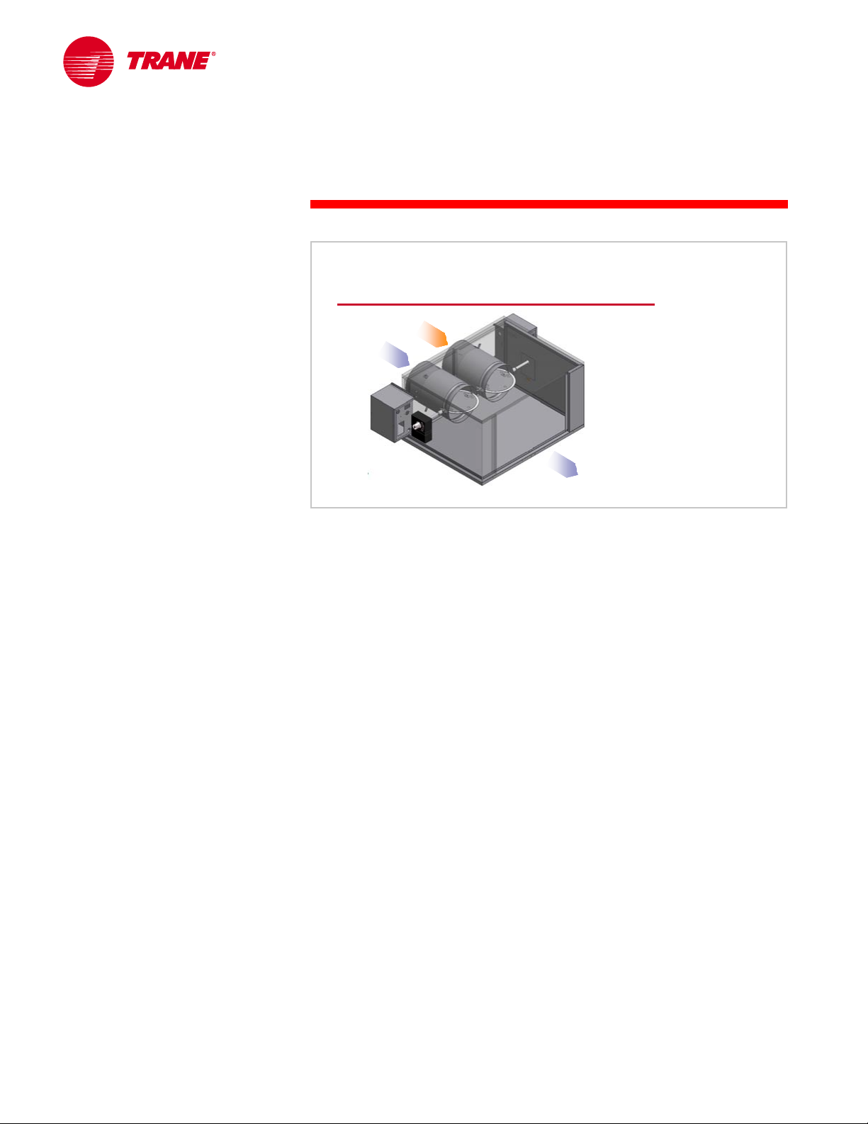
period three
System Configurations
VAV Systems
period three
System Configurations
Figure 55
To permit a complete understanding of the VAV system, we must look at it from
a system level. In this section we will explore a few common space types and
how VAV systems address the cooling and heating needs associated with them.
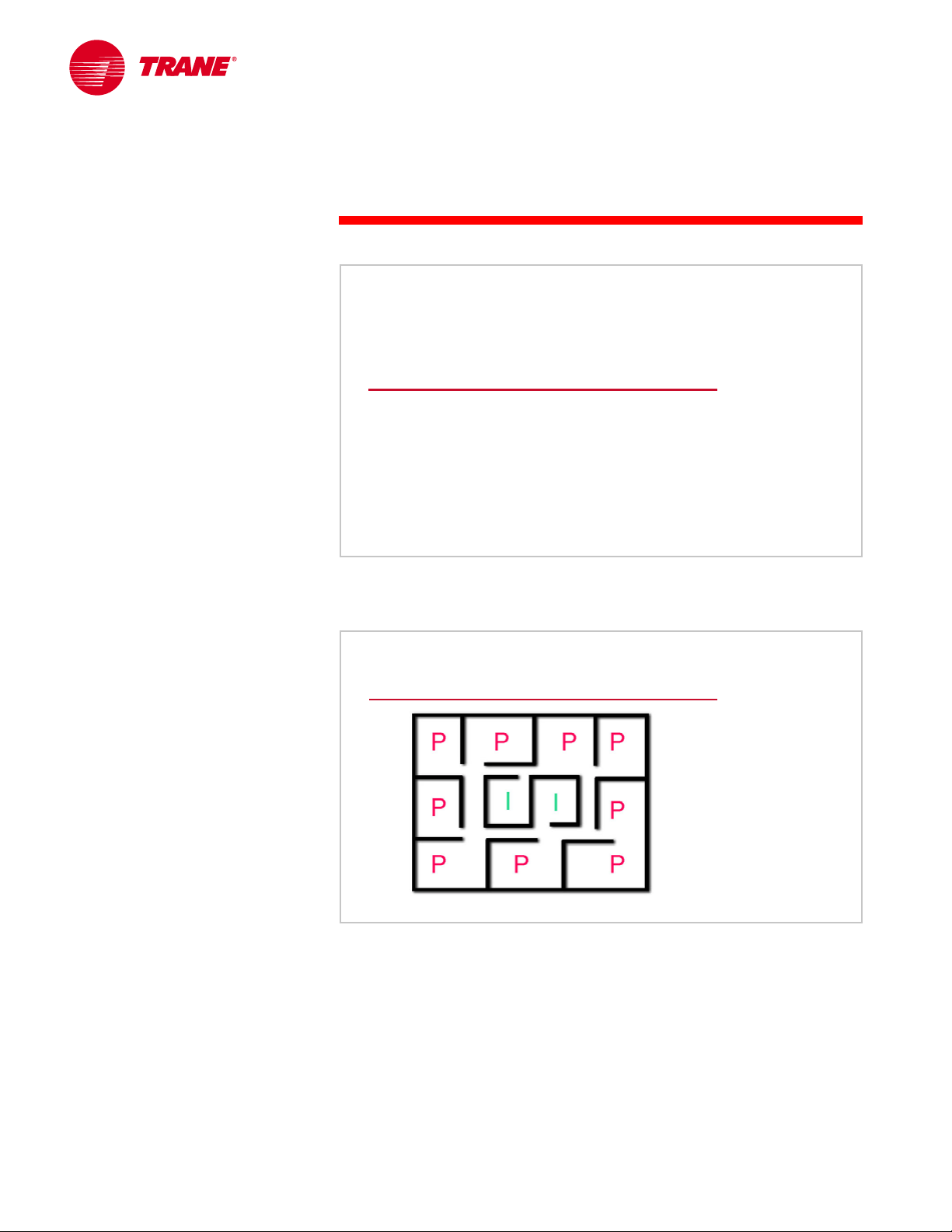
Perimeter (P) Versus Interior (I)
Figure 56
For simplicity, a typical building can be described as having two types of
spaces, perimeter and interior.
In many climates, perimeter spaces with walls and windows exposed to the
outdoors require seasonal cooling and heating. Such spaces require cooling in
the summer: it is warm outside, the sun is shining through the windows, people
are occupying the space, and the lights are on. In the winter, when it is cold
outside, these spaces require heating to offset the “skin” heat loss through the
exterior walls and windows.
Most interior spaces require year-round cooling due to the absence of skin
heat losses and the fairly consistent amount of heat generated by people, lights
40 TRG-TRC014-EN
Page 46

period three
System Configurations
notes
and equipment. Interior spaces on the top floor of a building often need to be
treated as a perimeter space due to the heat gain/loss from the roof.
Each space is typically served by an individual VAV terminal unit, allowing
independent cooling and heating control.
Perimeter Spaces
overhead
heating
perimeter
heating
Figure 57
Perimeter Spaces
Before a VAV terminal unit can be selected to serve a perimeter space, the
designer must determine the heating load for that space. This will determine
whether the heating load can be satisfied by supplying warm air through
overhead diffusers or if the heating load must be handled by a separate
perimeter heating system (e.g., baseboard wall fin).
The guideline for heating a perimeter space is based on the skin heat loss per
unit length of perimeter wall.
TRG-TRC014-EN 41
Page 47

notes
period three
System Configurations
Baseboard Perimeter Heating
heat loss > 450 Btu/hr/ft
heat loss > 450 Btu/hr/ft
baseboard
baseboard
heating system
heating system
If the heat loss of the perimeter space exceeds 450 Btu/hr per linear foot [430 W
per linear meter] of outside wall, an under-the-window, or baseboard, heating
system is typically used. With this much heat loss, supplying a high quantity of
warm air from overhead diffusers can cause downdrafts, leading to occupant
discomfort.
[430 W/m]
[430 W/m][430 W/m]
cooling--
only
cooling
VAV terminal unit
VAV terminal unit
only
Figure 58
The cooling requirements of these perimeter spaces are served by a coolingonly terminal unit. The diffusers are located in the center of the room in order to
evenly supply cool air to the space.
During heating mode, the terminal unit provides minimum airflow to the space
to meet the ventilation requirement. The perimeter heat source is separate, but
can be controlled by the VAV terminal unit controller. Having only one
controller for the space ensures proper sequencing of the cooling and heating
systems.
42 TRG-TRC014-EN
Page 48

notes
period three
System Configurations
Overhead Supply Perimeter Heating
diffusers in
diffusers in
center of space
center of space
< 250 Btu/hr/ft
< 250 Btu/hr/ft
diffusers blanket
diffusers blanket
perimeter wall
perimeter wall
250--
450 Btu/hr/ft
250
450 Btu/hr/ft
[240--
430 W/m]
[240
430 W/m]
If the heat loss of the perimeter space is less than 450 Btu/hr per linear foot [430
W per linear meter] of outside wall, downdrafts are less problematic and heated
air supplied through ceiling diffusers can provide a satisfactory solution.
[430 W/m]
[430 W/m]
Figure 59
Again, the rate of heat loss is used to determine the proper diffuser location. If
the heat loss is between 250 and 450 Btu/hr per linear foot [240 and 430 W per
linear meter] of outside wall, diffusers should discharge directly downward and
blanket the perimeter walls with heated air.
If the heat loss is less than 250 Btu/hr per linear foot [240 W per linear meter] of
outside wall, diffusers can be located in the center of the room and still provide
adequate blanketing to handle the heat loss.
TRG-TRC014-EN 43
Page 49

notes
period three
System Configurations
VAV Reheat
heat loss < 250 Btu/hr/ft
heat loss < 250 Btu/hr/ft
When overhead heating is acceptable, VAV reheat, fan-powered, or dual-duct
terminal units can be used to provide both perimeter cooling and heating.
[240 W/m]
[240 W/m][240 W/m]
VAV reheat
VAV reheat
terminal unit
terminal unit
Figure 60
In cooling mode, the VAV reheat terminal unit modulates in response to the
changing space cooling load, always maintaining a minimum airflow to serve
ventilation requirements. For space loads below this minimum airflow, the unit
maintains this constant minimum airflow and modulates the reheat coil
capacity to satisfy the space tempering or heating requirements.
Reheating previously-cooled primary air is not energy efficient. However,
because the VAV system has already reduced the supply airflow, it must reheat
only a limited amount of air. The VAV reheat system is far more energy efficient
than a similarly-applied, constant-volume reheat system.
44 TRG-TRC014-EN
Page 50

notes
period three
System Configurations
Fan-Powered VAV
heat loss < 250 Btu/hr/ft
heat loss < 250 Btu/hr/ft
Similarly, fan-powered terminal units can be used in perimeter spaces that
require seasonal cooling and heating.
[240 W/m]
[240 W/m][240 W/m]
parallel,
parallel,
fan--
powered VAV
fan
powered VAV
terminal unit
terminal unit
Figure 61
In the heating mode, the parallel, fan-powered unit turns on a small fan as the
first stage of heating. Doing so allows it to temper the supply air with the heat
(of the building and lights) that is carried by the return air, rather than using
“new” energy. When activated, the small fan also increases airflow to the
space, improving the mixing of supply air and space air to prevent stagnation.
Series, fan-powered terminal units may also be used in this manner. They offer
the added advantage of supplying constant airflow to the space in both cooling
and heating modes.
Dual-Duct VAV
warm
heat loss < 250 Btu/hr/ft
heat loss < 250 Btu/hr/ft
[240 W/m]
[240 W/m]
[240 W/m]
warm
primary air
primary air
dual--
duct VAV
dual
duct VAV
terminal unit
terminal unit
cool
cool
primary air
primary air
Figure 62
Finally, dual-duct VAV terminal units can also be used to heat and cool
perimeter spaces. The specific operation of a dual-duct system was explained in
Period Two.
TRG-TRC014-EN 45
Page 51

notes
period three
System Configurations
Interior Spaces
cooling--
only
cooling
only
VAV terminal unit
VAV terminal unit
Figure 63
Interior Spaces
Because an interior space is surrounded by spaces at the same temperature, it
does not experience the same heat gain and loss fluctuations as a perimeter
space. Therefore, an interior space typically requires some degree of cooling all
year long to overcome the heat generated by people, lighting, and so forth.
Most interior spaces are served by cooling-only terminal units that modulate in
response to the changing space cooling load. They also have a minimum
airflow setting to serve ventilation requirements.
Interior Spaces, Reheat Required
VAV reheat
VAV reheat
terminal unit
terminal unit
Figure 64
Some types of interior spaces such as conference rooms require some amount
of tempering to avoid overcooling the space at part loads. This is common for
spaces in which the occupancy varies from full occupancy to two or three
people.
46 TRG-TRC014-EN
Page 52
period three
System Configurations
notes
Typically, either VAV reheat or fan-powered terminal units are used to provide
the tempering needed to balance the reduced cooling load.
Small Buildings
Figure 65
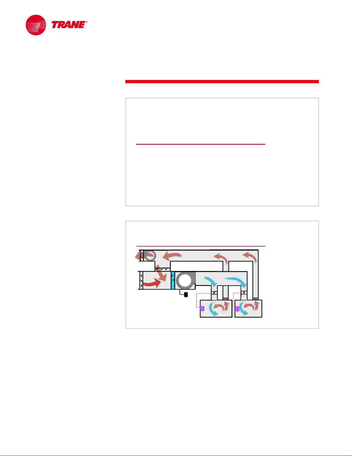
Changeover/Bypass VAV System
Many smaller buildings cannot afford commercial, or applied, equipment. Often
constant-volume, light-commercial equipment, like a small packaged rooftop
unit, will be used.
Nevertheless, it may still be desirable to accommodate many independently
controlled spaces economically. For these applications, a special VAV system
called a changeover/bypass VAV system is available.
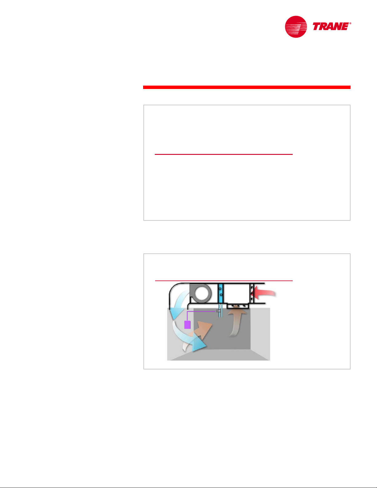
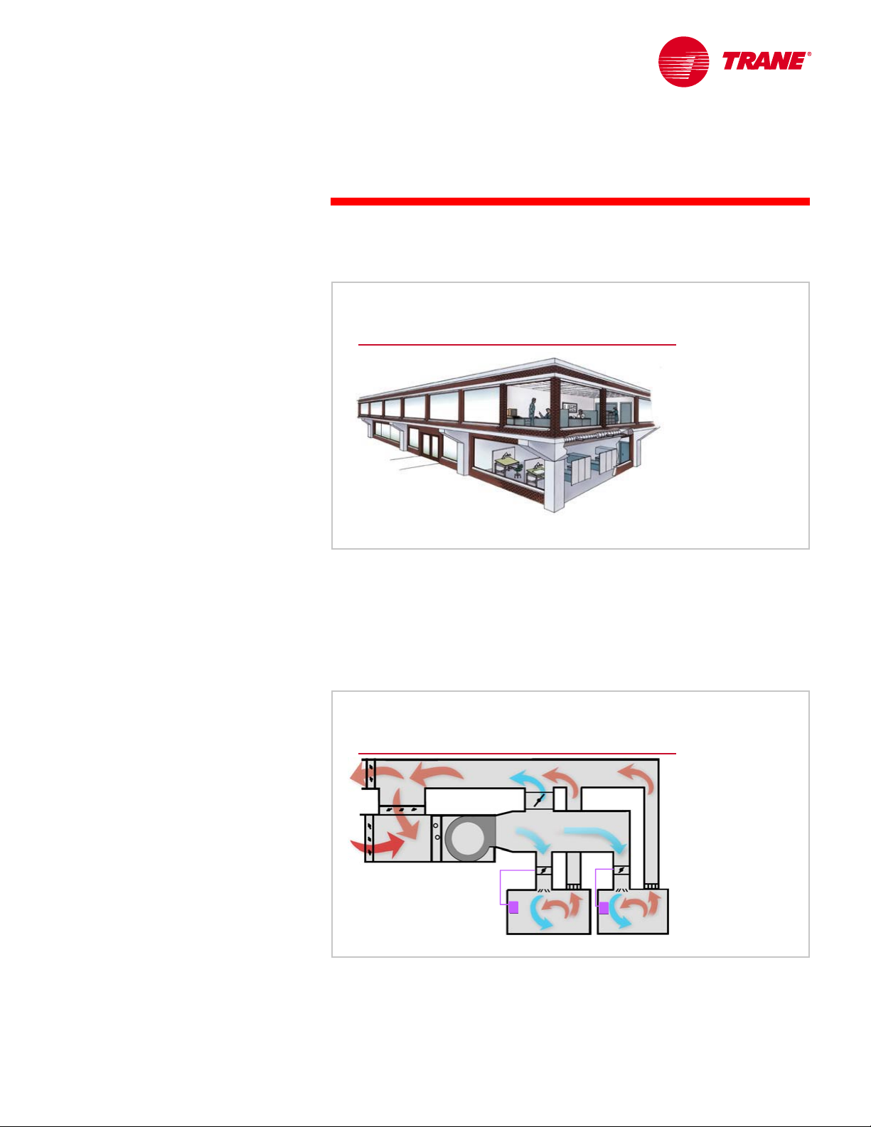
Changeover/Bypass VAV System
EA
bypass damper
bypass damper
fan
fan
PA
VAV
VAV
damper
damper
SA
supply
OA
constant--
constant
VAV to spaces
VAV to spaces
Like a typical VAV system, a changeover/bypass VAV system contains an
airflow-modulation device for each individually controlled space. This device
modulates supply airflow in response to the space load. Instead of modulating
the central supply fan, however, this system supplies constant primary airflow.
TRG-TRC014-EN 47
volume supply fan
volume supply fan
supply
RA
Figure 66
Page 53

period three
System Configurations
notes
Any unneeded air is diverted to the return air stream, allowing individual
comfort control of the spaces.
At part-load conditions, when more of the primary air bypasses the space, the
mixture of previously conditioned primary air and recirculated return air cuts
energy use at the cooling and heating equipment. This explains the use of the
term “bypass” in the name of this system. However, due to the fan providing a
constant airflow, no fan energy savings is realized at part-load conditions.
The term “changeover” refers to how this system handles the cooling and
heating requirements of the building. The central air handler can provide either
cooled or heated primary air to the space terminal units, and it makes this
decision by periodically “polling” the spaces. Because it can only provide
heating or cooling at a given time, this system is most appropriately used for
smaller buildings that have a minimal number of incidences where heating is
required in some spaces and cooling is simultaneously required in others.
System-Level Control Modes
▲ Occupied mode
▲ Unoccupied mode
▲ Morning warm-up/cool-down mode
Figure 67
System-Level Control Modes
When designing a VAV system for a commercial application, three system-level
control modes need to be addressed:
n Occupied mode
n Unoccupied mode
n Morning warm-up/cool-down mode
48 TRG-TRC014-EN
Page 54

notes
period three
System Configurations
Occupied Mode
▲ Main supply fan operates continuously
▲ Constant primary-air set point
▲ Main supply fan controlled to maintain the
system static-pressure set point
▲ Outdoor air damper delivers proper amount of
ventilation air
▲ Terminal units maintain respective “occupied”
space thermostat set points
Figure 68
In a typical commercial building, the occupied mode occurs during daytime
operation. The building must be ventilated and the comfort cooling or heating
temperature set points must be maintained in all occupied zones.
The occupied mode is characterized as follows:
n The main supply fan operates continuously.
n The primary air temperature is controlled to a constant set point.
n The supply fan is controlled to maintain the static-pressure set point of the
system.
n The outdoor air damper is controlled to deliver the proper amount of
ventilation air.
n All terminal units are controlled to maintain their respective occupied space
temperature set points.
TRG-TRC014-EN 49
Page 55

notes
period three
System Configurations
Unoccupied Mode
▲ Main supply fan operates only as needed to
maintain thermostat set points
▲ Main supply fan controlled to maintain the
system static-pressure set point
▲ Outdoor air damper is closed
▲ Terminal units maintain respective
“unoccupied” space thermostat set points
Figure 69
In a typical commercial facility, the unoccupied mode occurs at night. The
building does not require ventilation because it is not occupied, and the
temperature in the perimeter spaces must be prevented from getting too cold
(perhaps 60°F [15.6°C]) or too hot (perhaps 85°F [29.4°C]). Temperature control
of the interior spaces is typically ignored because proper control of the
perimeter spaces normally adequately limits the interior space temperatures.
The top floor of the building may require temperature limiting for all spaces.
During the unoccupied mode, the following occurs:
n The main supply fan cycles on whenever any perimeter space or a centrally
located nighttime thermostat demands heating or cooling. If separate
perimeter heat is installed and heat is demanded, it will operate and the
main supply fan remains off.
n The supply fan is controlled to maintain the static-pressure set point of the
system.
n The outdoor air damper is closed.
n All terminal units with demand for central heating or cooling maintain their
respective unoccupied temperature set points. All other terminal units
remain off.
50 TRG-TRC014-EN
Page 56

notes
period three
System Configurations
Morning Warm-up/Cool-down Mode
▲ Main supply fan operates continuously
▲ Main supply fan controlled to maintain the
system static-pressure set point
▲ Outdoor air damper is closed, unless required
for preoccupancy purge
▲ Terminal units are either fully open or
modulated to maintain their respective
“occupied” space thermostat set points
Figure 70
The morning warm-up/cool-down mode typically occurs as a transition from
the unoccupied mode to the occupied mode. It establishes the occupied
comfort conditions for the building as rapidly as possible, because they were
allowed to drift from occupied set point during the unoccupied mode, usually
to save energy.
In this mode, the building does not initially require ventilation because it is not
occupied, but it may eventually be provided for a preoccupancy purge (diluting
the contaminants that accumulated during the unoccupied mode).
During the morning warm-up/cool-down mode, the system is controlled as
follows:
n The AHU fan operates continuously to provide primary air to the spaces for
cooling or heating. If separate perimeter heat is installed and heat is
demanded, the perimeter heat source operates and the AHU fan remains off.
n The supply fan is controlled to maintain the static-pressure set point for the
system.
n The outdoor air damper is closed unless ventilation is needed for
preoccupancy purge.
n The terminal units may be fully open, allowing “wild” (uncontrolled) warm-
up or cool-down, or they may modulate to achieve the occupied
temperature set points for a “controlled” warm-up or cool-down.
Morning warm-up or cool-down mode is ended when the perimeter zone
thermostats or a single, representative thermostat reaches its occupied set
point. Then the system switches to the occupied mode.
TRG-TRC014-EN 51
Page 57

notes
period four
Fan Modulation
VAV Systems
period four
Fan Modulation
Figure 71
To accommodate the variable-volume requirements imposed by a VAV system,
the system supply fan must be selected and controlled in such a manner that it
is capable of modulating over the required airflow range without entering an
unstable area of operation.
First, certain VAV system basics should be reviewed, including:
n The fan performance curve
n The system resistance curve
n The fan modulation curve
Fan Performance Curve
2.7 in. H
O
2.7 in. H
O
2
2
[672.5 Pa]
[672.5 Pa]
static pressure
static pressure
airflow
airflow
Fan Performance Curve
The fan performance curve of a centrifugal fan is a plot of the airflow
capacity at a given speed (rpm) versus the static pressure it generates. While a
centrifugal fan produces both static and velocity pressures, it is traditional to
1
1
,
,
0
0
0
0
0
0
r
r
24,000 cfm
24,000 cfm
3
3
[11.3 m
/s]
[11.3 m
/s]
p
p
m
m
Figure 72
52 TRG-TRC014-EN
Page 58

period four
Fan Modulation
notes
plot performance on the basis of the static pressure component only.
Performance curves published for some packaged air handlers will include the
effects of the dampers, filters, and coils that are in the unit. In this case, the
static pressure capacity of the fan must be able to overcome the rest of the
static pressure losses in the system (supply duct, terminal units, diffusers and
grilles, and so forth).
To deliver 24,000 cfm [11.3 m3/s] of air, this example fan, running at 1,000 rpm,
generates 2.7 in. H
O [672.5 Pa] of static pressure.
2
System Resistance Curve
system
system
system
resistance
resistance
resistance
curve
curve
curve
2.7 in. H
O
2.7 in. H
O
2
2
[672.5 Pa]
static pressure
static pressure
[672.5 Pa]
1.05 in. H
1.05 in. H
[261.5 Pa]
[261.5 Pa]
O
O
2
2
15,000 cfm
15,000 cfm
[7.1 m
[7.1 m
airflow
airflow
3
3
/s]
/s]
1
1
,
,
0
0
0
0
0
0
24,000 cfm
24,000 cfm
3
3
[11.3 m
/s]
[11.3 m
/s]
r
r
p
p
m
m
Figure 73
System Resistance Curve
The system resistance curve is a plot of the pressure drop, in terms of static
pressure, that the system (including the supply ductwork, duct fittings, terminal
units, diffusers and return grilles, coils, filters, dampers, and so forth) creates
over a range of airflows. When the airflow in a system increases, the resistance
also increases because more friction is experienced.
3
When delivering 15,000 cfm [7.1 m
O [261.5 Pa] of static pressure resistance.
H
2
TRG-TRC014-EN 53
/s], this example system creates 1.05 in.
Page 59

notes
period four
Fan Modulation
Operating Point
performance
performance
performance
curve
curve
curve
2.7 in. H
O
2.7 in. H
O
2
2
[672.5 Pa]
[672.5 Pa]
static pressure
static pressure
airflow
airflow
When the system resistance curve is superimposed on the fan curve, the
intersection predicts the airflow and static pressure at which the system will
balance (operating point “A”).
system
system
system
resistance
resistance
resistance
curve
curve
curve
A
1
1
,
,
0
0
0
0
0
0
24,000 cfm
24,000 cfm
3
3
[11.3 m
/s]
[11.3 m
/s]
r
r
p
p
m
m
Figure 74
Running the fan in this example at 1,000 rpm will satisfy the design
requirements of the system by overcoming 2.7 in. H
pressure resistance while moving 24,000 cfm [11.3 m
O [672.5 Pa] of static
2
3
/s] of air.
"Riding the Fan Curve"
actual system
actual system
actual system
resistance curve
resistance curve
resistance curve
3.15 in. H
O
3.15 in. H
[784.6 Pa]
[784.6 Pa]
2.7 in. H
2.7 in. H
[672.5 Pa]
[672.5 Pa]
O
2
2
static pressure
static pressure
increase
increase
O
O
2
2
During operation, a VAV system experiences changes in resistance as the
VAV terminal units modulate. This creates a new system resistance curve.
In response, a constant-speed fan “rides up” the performance curve from the
design operating point (A) to a new balance point (B). This new operating point
is at lower airflow (18,000 cfm [8.5 m
O [784.6 Pa]). This method of modulating the airflow of the fan is called
H
2
“riding the fan curve.”
B
18,000 cfm
18,000 cfm
[8.5 m
[8.5 m
3
3
/s]
/s]
design system
design system
design system
resistance curve
resistance curve
resistance curve
A
1
1
,
,
0
0
0
0
0
0
r
r
p
p
m
m
airflow reduction
airflow reduction
24,000 cfm
24,000 cfm
3
3
[11.3 m
/s]
[11.3 m
/s]
3
/s]) and a higher static pressure (3.15 in.
Figure 75
54 TRG-TRC014-EN
Page 60

notes
period four
Fan Modulation
Forward-Curved Centrifugal Fan
input power
input power
3.15 in. H
3.15 in. H
[784.6 Pa]
[784.6 Pa]
2.7 in. H
2.7 in. H
[672.5 Pa]
[672.5 Pa]
O
O
2
2
O
O
2
2
B
A
1
1
,
,
0
0
0
0
0
0
r
r
p
p
m
m
18,000 cfm
18,000 cfm
[8.5 m
[8.5 m
3
3
/s]
/s]
24,000 cfm
24,000 cfm
3
3
[11.3 m
/s]
[11.3 m
/s]
Figure 76
This “riding the fan curve” method of modulation can be used with any
centrifugal fan. However, it is most energy efficient when applied to forwardcurved (FC) fans. The configuration of the input power curves of the
FC fan are such that input power requirements drop as the fan operating point
moves upward along the constant-speed performance curve.
“Riding the fan curve” can be used successfully when the airflow modulation
range for the system is small. On the other hand, if the system is required to
modulate over a wide range of airflows, the increased static pressure
experienced at reduced airflows may overpressurize the VAV terminals,
resulting in greater-than-desired space airflow and noise problems.
Additionally, if the fan enters an unstable area of operation at this high static
pressure, fan vibration, called “surge”, and severe air pulsation within the duct
system, may result. This may lead to objectionable noise levels and potentially
a mechanical fan failure.
TRG-TRC014-EN 55
Page 61

notes
period four
Fan Modulation
Fan Modulation Curve
VAV system
VAV system
modulation curve
modulation curve
static pressure
static pressure
sensor
sensor
set point
set point
airflow
airflow
Fan Modulation Curve
The fan modulation curve illustrates the static pressure requirement of the
VAV system over the range of airflows. This requirement consists of a fixed
component and a variable component.
The VAV system requires a minimum amount of static pressure to properly
operate the terminal-unit modulation devices and diffusers. This static pressure
is the fixed component.
The second component of this static pressure curve is variable. This is the
amount of static pressure required to overcome the system pressure losses due
to the ducts, fittings, coils, filters, and so forth, at various airflows. These losses
vary with changes to the system airflow.
Figure 77
This curve describes the fan modulation needed to balance the static pressure
that is required to offset these variable system losses (demand) with the static
pressure produced by the fan (supply).
56 TRG-TRC014-EN
Page 62

notes
period four
Fan Modulation
Fan Control Loop
static--
pressure
static
pressure
sensor
supply
supply
fan
fan
To achieve this balance, a simple control loop is used. First, the static pressure
is sensed from a particular location in the system. Second, a controller
compares this static pressure reading and the set point of the system. Finally,
the fan capacity is controlled to deliver the required airflow, at a static pressure
that maintains this set point at the location of the system sensor.
sensor
controller
controller
Figure 78
VAV Fan Modulation
actual system
actual system
resistance curve
resistance curve
design system
design system
resistance curve
resistance curve
A
VAV system
VAV system
modulation curve
modulation curve
static pressure
static pressure
sensor
sensor
set point
set point
We will use an exaggerated example to illustrate this system operation.
Assume that the load on the system decreases, causing all or part of the VAV
terminal units to modulate closed. This causes the system resistance curve to
shift upwards.
In response, the fan begins to “ride up” the constant-speed performance curve
from the design operating point (A), trying to reach the balance point with this
new system resistance curve. As a result, the fan delivers a lower airflow at a
higher static pressure.
B
airflow
airflow
Figure 79
TRG-TRC014-EN 57
Page 63

period four
Fan Modulation
notes
The system static pressure controller senses this higher pressure and sends a
signal to the supply fan to reduce capacity. Modulating the fan capacity results
in a new fan performance curve and the system balances at an operating point
(B) along the fan modulation curve, bringing the system static pressure back
down to the set point.
Fan Modulation Methods
▲ Discharge dampers
▲ Inlet vanes
▲ Fan-speed control
▲ Variable-pitch blade control
Figure 80
Fan Modulation Methods
The four methods commonly used to modulate fan capacity are: discharge
dampers, inlet vanes, fan-speed control, and variable-pitch blade control.
We will examine these now.
Discharge Dampers
supply
supply
fan
fan
discharge
discharge
dampers
dampers
Figure 81
Discharge dampers match the static pressure supplied by the fan with the
static pressure required by the system. They accomplish this by adding staticpressure loss to the system a little bit downstream of the fan.
58 TRG-TRC014-EN
Page 64

notes
period four
Fan Modulation
Discharge Dampers
discharge
discharge
damper
damper
SP loss
SP loss
actual system
actual system
resistance curve
resistance curve
design system
design system
resistance curve
resistance curve
A
static pressure
static pressure
As the VAV terminal units modulate shut, the system resistance curve shifts
upwards. The fan begins to “ride up” the constant-speed performance curve,
from the design operating point (A), trying to reach the balance point with this
new system resistance curve. As a result, the fan delivers a lower airflow at a
higher static pressure.
The system static pressure controller senses this higher pressure and sends a
signal to the discharge dampers, instructing them to begin closing. This has no
effect on the performance curve for the fan, but it does add a new staticpressure loss to the system. This moves the system resistance curve back down
to where the system balances at an operating point along the desired fan
modulation curve (B). This brings the system static pressure back down to its
set point.
Other methods are more energy efficient, so discharge dampers are rarely used
for supply fan modulation.
B
airflow
airflow
Figure 82
TRG-TRC014-EN 59
Page 65

notes
period four
Fan Modulation
Inlet Vanes
inlet
inlet
vanes
vanes
supply
supply
fan
fan
Figure 83
Inlet vanes modulate the capacity of a fan by “pre-swirling” the air in the
direction of fan wheel rotation before it enters the wheel.
By changing the angle of air entry into the fan, the modulating inlet vanes
lessen the ability of the fan wheel to “bite” the air. This reduces the airflow
capacity which, in turn, reduces the power consumption and the ability to
generate static pressure.
Inlet Vanes
actual system
actual system
resistance curve
resistance curve
design system
design system
resistance curve
resistance curve
80%
80%
A
90%
90%
100%
100%
Figure 84
inlet vane
inlet vane
position (%)
position (%)
static pressure
static pressure
This illustrates how inlet vanes control the fan operating point so that it tracks
the desired modulation curve in response to reduced airflow and rising system
static pressure.
By closing the inlet vanes, the performance curve for the fan shifts downward.
The airflow and resulting static pressure fall until the operating point balances
along the fan modulation curve (B).
B
airflow
airflow
60 TRG-TRC014-EN
Page 66

notes
period four
Fan Modulation
Fan-Speed Control
supply
supply
fan
fan
variable--
variable
speed drive
speed drive
Figure 85
Fan-speed control modulates fan capacity by varying the speed of rotation.
This is commonly accomplished using a variable-speed drive on the fan motor.
Fan-Speed Control
actual system
actual system
resistance curve
resistance curve
design system
design system
resistance curve
resistance curve
A
VAV system
VAV system
modulation curve
modulation curve
static pressure
static pressure
B
8
8
0
0
airflow
airflow
0
0
r
r
p
p
In response to reduced airflow and rising system static pressure, adjustable
fan-speed control produces a system/fan interaction that is similar to that
produced by inlet vane control.
By reducing the fan speed, the performance curve for the fan shifts downward,
and the airflow and resulting static pressure decrease until the operating point
(B) balances along the fan modulation curve.
1
1
,
,
0
0
0
0
9
9
0
0
0
0
0
0
r
r
p
p
r
r
m
m
p
p
m
m
m
m
Figure 86
TRG-TRC014-EN 61
Page 67

notes
period four
Fan Modulation
Variable-Pitch Blade Control
variable--
pitch
variable
pitch
blades
blades
Figure 87
Finally, the capacity of vaneaxial fans can be modulated by adjusting the pitch
angle of the actual fan blades. This diagram shows a set of fan blades that can
swivel to modulate the capacity of the fan.
This method of fan modulation is typically only found on very large systems.
Most vaneaxial fans modulate their capacity by varying the speed of the fan.
Variable-Pitch Blade Control
actual system
actual system
resistance curve
35°
resistance curve
design system
design system
resistance curve
resistance curve
A
50°
45°
40°
blade pitch (angle)
blade pitch (angle)
Figure 88
stall
stall
region
region
VAV system
VAV system
modulation curve
modulation curve
static pressure
static pressure
B
airflow
airflow
Note that the fan performance characteristics of this type of fan are slightly
different from those of a centrifugal fan. Performance is plotted based on
airflow at various blade angles versus total pressure (static pressure plus
velocity pressure).
The broken line defines the airflow and total pressure range that produces a
stall condition for each blade angle. Operation in the stall region is
characterized by separation of the air at the fan blade surface, resulting in
instability.
62 TRG-TRC014-EN
Page 68

period four
Fan Modulation
notes
In response to reduced airflow and rising system static pressure, the variablepitch vaneaxial fan responds similarly to a centrifugal fan with either inlet-vane
or variable-speed capacity control.
By changing the angle of the fan blades, the performance curve for the fan
shifts downward, and the airflow and resulting pressure decrease until the
operating point (B) balances along the fan modulation curve.
Fan Modulation Comparisons
100
100
90
90
80
80
70
70
60
60
50
50
FC fan with
FC fan with
discharge
discharge
40
40
dampers
dampers
% design power
% design power
30
30
20
20
10
10
0
0
These curves describe the performance characteristics of each fan modulation
method, in terms of the fan power required versus the percent of design
airflow. Realize that these are generalized curves based on an arbitrary set of
test conditions.
On a generalized basis, the forward-curved (FC) centrifugal fan with inlet vanes,
the variable-pitch vaneaxial fan, and fan speed control are similar in
performance.
To obtain a more accurate comparison for specific operating conditions, a lifecycle cost analysis should be performed.
BI fan with
BI fan with
discharge
discharge
dampers
dampers
AF fan with
AF fan with
inlet vanes
inlet vanes
fan--
fan
control
control
variable--
pitch
variable
pitch
vaneaxial
vaneaxial
10102020303040405050606070
% design airflow
% design airflow
FC fan with
FC fan with
inlet vanes
inlet vanes
speed
speed
70
80 90 100
80 90 100
Figure 89
TRG-TRC014-EN 63
Page 69

notes
period four
Fan Modulation
Controlling System Static Pressure
▲ Fan outlet static-pressure control
▲ Supply duct static-pressure control
▲ Optimized static-pressure control
Figure 90
System Static-Pressure Control
Each of these fan-capacity control methods requires a signal from a controller
that monitors static pressure, using a sensor located somewhere in the supplyduct system. This controller compares the sensed pressure to a set point and
modulates the fan capacity to maintain a set point at that sensor location.
There are three common methods for sensing and controlling system static
pressure. They are: fan outlet static-pressure control, supply duct staticpressure control, and optimized static-pressure control.
Fan Outlet Static-Pressure Control
sensor located
at fan outlet
static
static
pressure
pressure
sensor
sensor
VAV
VAV
terminal units
terminal units
supply
supply
fan
fan
Figure 91
For the fan outlet static-pressure control method, the static pressure
sensor is mounted near the outlet of the main supply fan. The controller is set
to maintain the static pressure required at design flow.
The appeal of this method is that the sensor can be factory-installed and tested,
resulting in greater reliability and no field installation cost. If fire dampers are
64 TRG-TRC014-EN
Page 70

period four
Fan Modulation
notes
included in the supply duct, this method ensures that the sensor is on the fan
side of the damper so that the duct is protected from high pressures. Also,
depending on the layout of the duct system, this method may eliminate the
need for multiple duct-mounted sensors. It is not, however, as energy efficient
as the other methods.
Supply Duct Static-Pressure Control
sensor located
2/3 down supply duct
static
static
pressure
pressure
sensor
sensor
supply
supply
fan
fan
For the supply duct static-pressure control method, the static pressure
sensor is located somewhere in the supply duct system. Typically the location
of the sensor, and consequently the set point of the controller, is two-thirds of
the distance between the supply fan outlet and the critical terminal-unit inlet.
The critical terminal unit is at the end of the supply duct path that represents the
largest total pressure drop.
VAV
VAV
terminal units
terminal units
Figure 92
The sensor is field-installed, and the controller is set to maintain the pressure
corresponding to that location in the duct system at design airflow conditions.
In larger systems with many terminal units, determining the best sensor
location for all load conditions can be difficult—often determined by trial and
error and requiring multiple sensors. Field installation and adjustment of one
or possibly several duct pressure sensors increases installation cost. Without
factory testing, reliability may also suffer compared to the fan outlet method
previously discussed. However, using this method typically allows for fan
energy savings compared to the fan outlet method.
TRG-TRC014-EN 65
Page 71

notes
period four
Fan Modulation
Optimized Static-Pressure Control
sensor located
at fan outlet
supply
supply
fan
fan
communicating
communicating
BAS
BAS
The optimized static-pressure control method combines the locationrelated benefits of fan outlet control with operating cost savings that exceed
those of supply duct static-pressure control. A single static-pressure sensor is
located at the fan outlet, and the controller dynamically adjusts the staticpressure set point based on the position of the modulating devices in the VAV
terminal units.
The DDC/VAV controllers know the position of their individual air-modulation
devices and, because they are pressure independent, they will modulate to
maintain the required airflow. The building automation system (BAS)
continually polls the VAV terminal units looking for the most-open VAV damper.
The controller resets the static-pressure set point so that at least one VAV
terminal, the one requiring the highest inlet pressure, is nearly wide open.
The result is that the supply fan generates only enough static pressure to get
the required flow through this “critical” terminal unit.
static
static
pressure
pressure
sensor
sensor
fan speed or
fan speed or
inlet vane position
inlet vane position
VAV
VAV
terminal
terminal
units
units
damper
damper
positions
positions
Figure 93
This method allows the sensor to be factory-installed and-tested. Because the
pressure sensor is at the fan outlet, it can also serve as the duct high-pressure
sensor. If the terminal units use DDC controls, the system-level
communications are already in place, making this the lowest-cost, highest
energy savings strategy.
66 TRG-TRC014-EN
Page 72

notes
period four
Fan Modulation
Part-Load Comparison
control
control
method
method
full load
full load
part load
part load
fan outlet
fan outlet
supply duct
supply duct
optimized
optimized
airflow
airflow
24,000
24,000
[11.3 m
[11.3 m
18,000
18,000
[8.5 m
[8.5 m
18,000
18,000
[8.5 m
[8.5 m
18,000
18,000
[8.5 m
[8.5 m
cfm
cfm
cfm
cfm
cfm
cfm
cfm
cfm
fan static
fan static
pressure
pressure
2.7 in. H
2.7 in. H
3
3
/s]
[672.5 Pa]
/s]
[672.5 Pa]
2.1 in. H
2.1 in. H
3
3
/s]
[523.1 Pa]
/s]
[523.1 Pa]
1.9 in. H
1.9 in. H
3
3
/s]
[473.3 Pa]
/s]
[473.3 Pa]
1.5 in. H
1.5 in. H
3
3
/s]
[373.6 Pa]
/s]
[373.6 Pa]
fan input
fan input
power
power
22 hp
O
22 hp
O
2
2
[16.4 kW]
[16.4 kW]
O
13 hp
O
13 hp
2
2
[9.7 kW]
[9.7 kW]
12 hp
O
12 hp
O
2
2
[8.9 kW]
[8.9 kW]
O
9.5 hp
O
9.5 hp
2
2
[7.1 kW]
[7.1 kW]
% full--
% full
power
power
100%
100%
60%
60%
55%
55%
43%
43%
load
load
Figure 94
A comparison of these static-pressure control methods demonstrates the
energy savings potential. At this representative part-load condition, using the
optimized static-pressure control method allows the supply fan to use only 43%
of its full-load power versus 55% for the supply duct static-pressure control
method.
In addition to the supply fan energy savings, because the optimized staticpressure control method allows the system to operate as if the static pressure
sensor was at each individual terminal unit, it ensures that no spaces are
“starved” for air. There are also acoustical benefits at part load by operating the
supply fan and VAV terminal units at the lowest possible duct static pressure.
TRG-TRC014-EN 67
Page 73

notes
period five
Application Considerations
VAV Systems
period five
Application Considerations
Figure 95
When designing a VAV system for a building, there are several considerations
to address:
n System-level ventilation
n Freeze protection for coils
n Part-load space humidity control
n Building pressure control
This is by no means the entire list of considerations when designing a VAV
system, but is representative of some of the key issues.
68 TRG-TRC014-EN
Page 74

notes
period five
Application Considerations
System-Level Ventilation
RA
OA
primary air (PA)
OA required
ventilation fraction
VAV #1
1000
1000
[0.47 m
[0.47 m
200
200
[0.09 m
[0.09 m
0.20
0.20
cfm
cfm
cfm
cfm
3
3
/s]
/s]
3
3
/s]
/s]
+
+
+
+
VAV #2
1000
1000
[0.47 m
[0.47 m
200
200
[0.09 m
[0.09 m
0.20
0.20
PA
VAV #3
cfm
1000
cfm
3000
cfm
1000
+
+
3
3
/s]
[0.47 m
/s]
[0.47 m
cfm
300
cfm
300
+
+
3
3
/s]
[0.15 m
/s]
[0.15 m
0.30
0.30
cfm
cfm
3000
cfm
=
=
3
3
cfm
cfm
3
3
3
3
/s]
[1.41 m
/s]
/s]
[1.41 m
/s]
700
cfm
700
cfm
=
=
3
3
/s]
[0.33 m
/s]
/s]
[0.33 m
/s]
Figure 96
System-Level Ventilation
During operation, a typical VAV system delivers a mixture of outdoor air and
recirculated air to the multiple spaces it serves. The volume of supply air that
enters a space is controlled by a temperature sensor in that space.
In contrast, the ventilation requirement for a space typically remains constant
as the supply airflow varies with thermal load. The challenge is to maintain the
proper amount of ventilation air to each individual space while varying the
supply air to that space in response to its load.
ASHRAE Standard 62–1999, Ventilation for Acceptable Indoor Air Quality,
includes a procedure that can be used to calculate the quantity of outside air
required at the central air-handling unit in order to satisfy the ventilation
requirements of the individual spaces. At part-load conditions, VAV systems
typically require a constant quantity of ventilation air, resulting in an increased
percentage of outdoor air at the air handler. Fixed-position dampers will result
in underventilated VAV systems.
TRG-TRC014-EN 69
Page 75

notes
period five
Application Considerations
Ventilation Reset
outdoor airflow
outdoor airflow
measurement
measurement
and control
and control
OA
With all three components, DDC controls on the VAV terminal units and air
handler, a method to measure outdoor airflow at the air handler, and a
communicating building automation system (BAS), a VAV system can use the
multiple-spaces equation (Equation 6-1) from Standard 62 to dynamically
operate the VAV system.
Each VAV terminal unit continuously monitors primary airflow. The DDC
controller also knows the ventilation air requirement. With this information, the
controller can continuously calculate the space ventilation fraction of the space,
or (the ventilation airflow required divided by the primary airflow being
delivered). The BAS periodically gathers this data from all the VAV terminal
units and solves Equation 6-1. This determines the amount of outdoor airflow
that must be introduced at the system level, at the central air handler, to satisfy
the ventilation requirements. The BAS then resets the outdoor airflow set point,
and the outdoor airflow measuring device controls the damper accordingly.
RA
central air handler
central air handler
with controls
with controls
communicating BAS
communicating BAS
PA
VAV terminal units
VAV terminal units
with DDC controls
with DDC controls
Figure 97
This method, called ventilation reset, ensures that all spaces are properly
ventilated at all load conditions while minimizing wasteful overventilation.
70 TRG-TRC014-EN
Page 76

notes
period five
Application Considerations
Freeze Protection for Coils
RA
80°F
80°F
[26.7°C]
[26.7°C]
warm air
warm air
OA
10°F
10°F
12.2°C]
[[--12.2°C]
Freeze Protection for Coils
As mentioned, proper VAV system ventilation often leads to a high percentage
of outdoor air at part-load conditions. Streams of air at vastly different
temperatures are difficult to mix and may cause the mixed air stream to stratify,
resulting in a risk of freezing the water inside the cooling coil.
cooling
cooling
coil
coil
mixed air
mixed air
cold air
cold air
Figure 98
Air blending devices, mixing baffles, and high-velocity mixing dampers can
provide effective mixing, but usually require more space in the air handler and
more fan power. As an alternative, preheating the outdoor air before it enters
the mixing box decreases this temperature difference, improves mixing and
offers freeze protection for cooling coils.
Measures to Prevent Coil Freeze-Up
▲ Drain coils during cold weather
▲ Keep water in motion
▲ Add glycol to the water
▲ Use face-and-bypass dampers to limit amount
of cold airflow through coil
▲ Preheat the outdoor air (heating coil, heat
recovery)
Figure 99
Even with effective mixing, the temperature of the mixed air entering the coil
may approach that of the outdoor air during cold weather. This may cause
water inside the cooling coil to freeze.
TRG-TRC014-EN 71
Page 77

period five
Application Considerations
notes
Coils can be protected from freezing in many ways, such as:
n Draining the coils during cold weather
n Keeping the water in motion
n Adding glycol to the water
n Using face-and-bypass dampers to limit the amount of cold airflow through
the coil
n Preheating the outdoor air with either a conventional heating coil or heat
recovered from the exhaust air stream
Part-Load Space Humidity Control
part--
load space conditions
part
load space conditions
CV system =
CV system =
VAV system =
VAV system =
75°F, 66% RH
75°F, 66% RH
[23.9°C]
[23.9°C]
75°F, 58% RH
75°F, 58% RH
[23.9°C]
[23.9°C]
CCCC
AAAA
AAAA
55°F
55°F
[12.8°C]
[12.8°C]
CCCC
60°F
60°F
[15.6°C]
[15.6°C]
DDDD
DDDD
mixed air
mixed air
BBBB
BBBB
75°F
75°F
[23.9°C]
[23.9°C]
humidity ratio
humidity ratio
dry--
bulb temperature
dry
bulb temperature
Figure 100
Part-Load Space Humidity Control
VAV systems do a good job of “indirectly” controlling space relative humidity
(RH) at full-and part-load conditions. A typical VAV system supplies air at a
constant, low dew-point temperature at all load conditions.
In this example, both the constant-volume and variable-volume systems deliver
the same quantity and temperature (A = 55°F [12.8°C]) of air to the space at
design load conditions. However, at part load the VAV system still supplies 55°F
[12.8°C] air to the space. This results in a lower space relative humidity
(B verses D) than the constant-volume system that modulates the coil capacity
and supplies warmer (C = 60°F [15.6°C]) air at the same part-load condition.
Realize that adding reheat to this constant-volume system will improve its
ability to control space relative humidity, but will also cause it to use more
energy.
This demonstrates the danger of using primary air temperature reset on VAV
systems! Increasing the primary air temperature on a VAV system will save
some cooling energy, but will require more fan energy and will result in higher
space relative humidity levels. ASHRAE Standard 62–1999 recommends that the
space relative humidity not exceed 60%. If temperature reset is used, it should
be allowed to be overridden by a space relative-humidity sensor.
72 TRG-TRC014-EN
Page 78

notes
period five
Application Considerations
Part-Load Supply Air Tempering
overcooled space conditions
overcooled space conditions
68°F, 74% RH
68°F, 74% RH
[20°C]
[20°C]
humidity ratio
humidity ratio
mixed air
mixed air
supply air
supply air
55°F
55°F
[12.8°C]
[12.8°C]
BBBB
BBBB
68°F
68°F
[20°C]
[20°C]
AAAA
AAAA
dry--
bulb temperature
dry
bulb temperature
Figure 101
Minimum space ventilation requirements often dictate minimum primary
airflow settings on VAV terminal units. If the space cooling load requires less
airflow than this minimum, the space may overcool (to B = 68°F [20°C] in this
example instead of the desired condition, A) unless the supply air is tempered.
Overcooling the space causes comfort problems and causes the relative
humidity to increase (to 74% here).
To avoid this, a method of tempering the supply air is needed. This can be done
using a terminal heating coil or by mixing in warm air from the plenum or from
a warm primary air stream of a dual-duct system.
Realize that if mechanical equipment is used to provide this supply air
tempering, it must be available not only to handle the space heating
requirements, but also to handle the tempering requirements during these
part-load cooling conditions.
TRG-TRC014-EN 73
Page 79

notes
period five
Application Considerations
Building Pressure Control
EA
OA
Building Pressure Control
Maintaining a slightly positive pressure inside buildings, especially in humid
climates, increases comfort and helps avoid indoor air quality (IAQ) problems
related to microbial growth and outdoor contaminant sources.
Whenever variable quantities of outdoor air are brought into a system, building
pressurization becomes a concern. Resetting the quantity of outdoor air in
response to part-load conditions, or using an outdoor air economizer, may lead
to undesirable changes in building pressure. Varying the quantity of outdoor air
requires the system to exhaust a similar quantity of air to avoid
overpressurizing or underpressurizing the building.
supply
supply
fan
fan
RA
PA
SA
Figure 102
Direct Pressurization Control
EA
relief
relief
fan
fan
supply
OA
controller
controllercontroller
outdoor
outdoor
outdoor
static pressure
static pressure
static pressure
There are several methods used to control building pressure in a VAV system.
The method that is commonly considered the best-suited for VAV applications
is direct control of a central relief fan.
74 TRG-TRC014-EN
supply
representative
representative
space static
space static
pressure
pressure
fan
fan
RA
SA
PA
Figure 103
Page 80

period five
Application Considerations
notes
A sensitive static-pressure controller directly compares the variations between
the space static pressure and the outdoor reference static pressure. The
controller modulates the capacity of a central relief fan to maintain a fixed
static-pressure difference, usually a slightly positive building pressure. The
space static-pressure sensor is typically located in the lobby or near the main
entrance.
TRG-TRC014-EN 75
Page 81

notes
period six
Review
VAV Systems
period six
Review
Figure 104
Now, we will review some of the main concepts from this clinic on variableair-volume (VAV) systems.
Review—Period One
RA
EA
OA
central
central
air handler
air handler
thermostat
thermostat
A variable-air-volume (VAV) air-conditioning system varies the volume of
constant-temperature primary air to meet changing load conditions in the
space. VAV systems can provide both fan and refrigeration energy savings at
part load, while efficiently serving many independently-controlled spaces with
dissimilar cooling and heating load requirements.
Variable thermal load profiles in the spaces, the need for multiple,
independently-controlled spaces, and the existence of a common return-air
path are three building characteristics that favor the application of VAV systems.
PA
VAV
VAV
box
box
SA
Air Conditioning Clinic TRG-TRC014 -EN© American Stan dard Inc. 2 001
Air Conditioning Clinic TRG-TRC014 -EN
Figure 105
76 TRG-TRC014-EN
Page 82

notes
period six
Review
Review—Period Two
fan-powered VAV
terminal unit
single-duct, cooling-only
VAV terminal unit
A simple VAV system is comprised of the following components:
n Central air handler
n Supply duct
n VAV terminal unit with thermostats and supply diffusers for each
independently controlled space
n Thermostat and unit controller for each terminal unit
n Return plenum or duct
There are various types of VAV terminal units, each one unique in its response
to changing space loads.
dual-duct VAV
terminal unit
Figure 106
TRG-TRC014-EN 77
Page 83

notes
period six
Review
Review—Period Three
interior spaces
perimeter spaces
Figure 107
A simple building has two types of spaces: perimeter and interior. These two
space types require different types of VAV terminal units to satisfy their
requirements. It is important to realize that many VAV systems include a
combination of different types of terminal units based on individual space
requirements.
Review—Period Four
actual system
actual system
resistance curve
resistance curve
design system
performance
performance
performance
curve
curve
curve
VAV system
VAV system
modulation curve
modulation curve
static pressure
static pressure
The VAV supply fan capacity is modulated in response to changing building
loads. Four methods of modulating fan capacity include: discharge dampers,
inlet vanes, fan speed control, and variable-pitch blade control.
Fan capacity is also controlled based on the static pressure in the system. There
are three common methods for sensing and controlling system static pressure:
fan outlet static-pressure control, supply duct static-pressure control, and
optimized static-pressure control.
B
airflow
airflow
design system
resistance curve
resistance curve
A
Figure 108
78 TRG-TRC014-EN
Page 84

notes
period six
Review
Review—Period Five
▲ System-level ventilation
▲ Freeze protection for coils
▲ Part-load space humidity control
▲ Building pressure control
Figure 109
Finally, when applying a VAV system to a building, there are several
considerations that must be addressed. They include: providing the correct
system-level ventilation, adequately protecting the coils from freezing,
controlling space humidity over a wide range of loads, and controlling building
pressure
Figure 110
For more information, refer to the following references:
n Trane Air Conditioning Manual
n Trane product catalogs for VariTrane™ and VariTrac™ VAV products (Trane
literature order numbers VAV-PRC002-EN and VAV-PRC003-EN)
n A Guide to Understanding ASHRAE Standard 62 (Trane literature
order number ISS-APG001-EN)
n ASHRAE Handbook — Systems and Equipment
TRG-TRC014-EN 79
Page 85

period six
Review
notes
Visit the ASHRAE Bookstore at www.ashrae.org.
For information on additional educational materials available from Trane,
contact your local Trane sales office (request a copy of the Educational
Materials price sheet—Trane order number EM-ADV1) or visit our online
bookstore at www.trane.com/bookstore/.
80 TRG-TRC014-EN
Page 86

Quiz
Questions for Period 1
1 Given a space sensible load of 30,000 Btu/hr [8,793 W], a space dry-bulb
temperature of 78°F[25.6°C], and a primary air dry-bulb temperature of
58°F [14.4°C]:
a What supply airflow is required to balance this load?
Assume the space sensible load is reduced to 18,000 Btu/hr [5,276 W]:
b For a constant volume system, what primary air temperature is required
to balance this new load?
c For a VAV system, what supply airflow is required to balance this
new load?
2 Because the VAV system supplies constant temperature air, how is
refrigeration energy savings realized at part load?
3 List three building characteristics that favor the application of VAV systems
in the building.
Questions for Period 2
4 Which type of single-duct VAV terminal unit allows for constant supply
airflow to the space?
5 Explain why fan-powered VAV terminal units can use air from the ceiling
plenum to provide the “first stage” of heating.
6 Explain the concept of pressure-independent control.
7 What is the principle employed by the linear slot diffuser to distribute air
within the space?
Questions for Period 3
8 When the heat loss exceeds 450 Btu/hr per linear foot [430 W/m per linear
meter] of exterior wall, what type of perimeter heating is generally
recommended?
9 Is the supply fan in a changeover/bypass system constant volume or
variable volume?
Questions for Period 4
10 How do inlet vanes cause the capacity of a fan to change?
TRG-TRC014-EN 83
Page 87

Quiz
notes
11 What method of static-pressure control provides the greatest power-
savings potential for a VAV system?
Questions for Period 5
12 What industry standard outlines a method for determining the proper
quantity of ventilation air to be introduced at the system-level air handler of
a multiple space system?
13 List two methods used to protect cooling coils from freezing.
84 TRG-TRC014-EN
Page 88

TRG-TRC014-EN 85
Page 89

Answers
1a 1,382 cfm [0.65 m
3
/s]
1b 63°F [17.2°C]
1c 829 cfm [0.39 m
3
/s]
2 The reduced airflow across the cooling coil at part load causes the
refrigeration system to throttle back in order to stabilize the supply air
temperature condition. IN turn, this results in a reduction in refrigeration
energy.
3 Variable thermal load profiles in the spaces, the need for multiple,
independently-controlled spaces, and the existence of a common return air
path
4 Series, fan-powered VAV
5 The air in the ceiling plenum is warmer than the space because it contains
heat from the building and lights.
6 A pressure-independent VAV control scheme directly controls the actual
volume of primary air that is flowing to the space. The position of the
modulation device is not directly controlled and is basically a by-product
of controlling the actual airflow through the unit. Because the airflow
delivered to the space is directly controlled, this airflow is independent
of the inlet static pressure.
7 Coanda effect
8 Baseboard, or under-the-window, heating
9 A constant-volume supply fan
10 Inlet vanes modulate the capacity of a fan by “pre-swirling” the air in the
direction of fan wheel rotation, before it enters the wheel. By changing the
angle of air entry into the fan, these modulating inlet vanes lessen the
ability of the fan wheel to “bite” the air.
11 Optimized static-pressure control
12 ASHRAE Standard 62–1999
13 Draining the coils during cold weather, keeping the water in motion, adding
glycol to the water, using face-and-bypass dampers to limit the amount of
cold airflow through the coil, or preheating the outdoor air
86 TRG-TRC014-EN
Page 90

Glossary
changeover/bypass VAV system A system that allows variable supply air to
the spaces but uses a constant-volume central supply fan. This is accomplished
by using a large damper to bypass the excess air. This is common in smaller
buildings requiring individual space comfort control.
Coanda effect Concept behind the operation of a linear slot diffuser. Air is
discharged at a relatively high velocity along the surface of the ceiling, creating
an area of low pressure that causes the supply air to hug the ceiling. As it
travels along the ceiling, air from the space is drawn into, and mixed with, the
supply airstream. When the air settles to the occupied levels of the space, it has
reached an average temperature.
constant-volume system Type of air-conditioning system that varies the
temperature of a constant volume of air supplied to meet the changing load
conditions of the space.
cooling-only terminal unit Simplest type of single-duct VAV terminal unit. It
has the capability of varying the airflow, but has no method for space heating.
diffuser Device connected to the end of the supply duct system, used to
distribute the supply air effectively to the conditioned space.
direct digital control (DDC) Method of terminal-unit control using an electric
motor to operate the airflow modulation-device activator. It uses a
microprocessor that enables digital communication between the unit controller
and a central building automation system.
discharge dampers Method of supply fan modulation that matches the static
pressure supplied by the fan with the static pressure required by the system.
This is accomplished by using a modulating damper a little bit downstream of
the fan to create a static-pressure drop in the system.
dual-duct terminal unit VAV terminal unit consisting of two primary airflow
modulation devices, one for cool primary air and one for warm primary air.
These units can be controlled to provide either a constant volume or a variable
volume of supply air to the space.
electronic control Method of terminal unit control using an electric motor
to operate the airflow modulation-device actuator. The motor can drive the
modulation device open or closed.
equal friction duct design method Method of designing an air duct system
that results in an equal static-pressure drop per foot of duct. Equal-friction duct
systems can be easily designed by hand.
fan modulation curve Curve that illustrates the static pressure requirement
of the VAV system fan over the range of airflows.
fan outlet static-pressure control Method of VAV system static-pressure
control that mounts the static-pressure sensor near the outlet of the main
supply fan and maintains a constant static pressure at the sensor.
fan performance curve Plot of the airflow capacity of a specific fan at a given
speed (rpm) versus the static pressure it generates.
TRG-TRC014-EN 87
Page 91

Glossary
fan speed control Method of supply-fan modulation that affects the capacity
of a fan by varying the speed of rotation—commonly accomplished using a
variable-speed drive on the fan motor.
fan-powered terminal unit Type of single-duct VAV terminal unit that can
provide heating for a space by mixing warm plenum air with the cool primary
air, using a small terminal fan.
inlet vanes Method of supply-fan modulation that affects the capacity of a
fan by “pre- swirling” the air in the direction of fan wheel rotation before it
enters the wheel. The inlet vanes lessen the ability of the fan wheel to “bite” the
air, reducing its airflow capacity.
interior space A conditioned space that is surrounded by other conditioned
spaces, with no perimeter walls or windows. Typically requires some degree of
cooling all year long to overcome the heat generated by people, lighting, and so
forth.
occupied mode Typical daytime operating mode of the system. The building
must be ventilated and the comfort cooling or heating temperature set points
must be maintained in all occupied spaces.
optimized static-pressure control Optimized method of VAV system staticpressure control that uses the benefit of DDC control, to continuously reset the
static pressure set point of the system so that the VAV terminal requiring the
highest inlet pressure is nearly wide open.
parallel fan-powered terminal unit A fan-powered VAV terminal unit
consisting of a primary airflow modulation device and a small, integral
constant-volume fan packaged to provide parallel airflow paths.
perimeter space A conditioned space with walls and windows that are
exposed to the outdoors. In most climates these spaces would require seasonal
cooling and heating.
pneumatic control Method of terminal unit control using pressurized air to
operate the airflow modulation-device actuator. The actuator consists of an
inflatable bladder and a return spring.
pressure-dependent VAV control scheme that uses the space temperature
sensor to directly control the position of the modulating device. The actual
airflow delivered to the space is a by-product of this position and depends on
the duct-system static pressure at the inlet of the terminal unit.
pressure-independent VAV control scheme that directly controls the actual
volume of primary air that flows to the space. The position of the modulation
device is not directly controlled and is basically a by-product of regulating the
airflow through the unit. Because the airflow delivered to the space is directly
controlled, it is independent of inlet static pressure.
primary air Conditioned air delivered by a central supply fan to a
terminal unit.
series fan-powered terminal unit A fan-powered VAV terminal unit
consisting of a primary airflow modulation device and a small, integral
88 TRG-TRC014-EN
Page 92

Glossary
constant-volume fan, packaged so that the airflow paths are in series.
This provides a constant volume of supply air to the space when operating.
static regain duct design method Method of designing an air duct system
that strives to maintain a fairly consistent static pressure throughout the entire
duct. Recommended for sizing the supply ducts upstream of the terminal units
in a VAV system. The design of a static regain duct system often requires the
use of a computer program.
supply air Conditioned air delivered to a space.
supply duct static-pressure control Method of VAV system static-pressure
control that mounts the static-pressure sensor somewhere in the supply duct
system, allowing the supply fan to decrease speed and lower the static pressure
in the system under part-load conditions.
supply duct system Transports the primary air from the central air handler
to the VAV terminal units and then on to the space diffusers.
system resistance curve Plot of the static pressure drop that the system
(including the supply ductwork, duct fittings, terminal units, diffusers and return
grilles, coils, filters, dampers, and so forth.) creates over a range of airflows.
unoccupied mode Typical nighttime operating mode of the system. The
building does not require ventilation because it is not occupied, and the space
temperatures are controlled to unoccupied set points.
variable-pitch blade control Method of fan modulation used on vaneaxial
fans. The capacity of the fan is modulated by adjusting the pitch angle of the
actual fan blades.
variable-air-volume system Type of air-conditioning system that varies the
volume of constant-temperature air supplied to meet the changing load
conditions of the space.
VAV reheat terminal unit Type of single-duct VAV terminal unit that can
provide space heating using a small heating coil.
VAV terminal unit Sheet-metal assembly installed upstream of space
diffusers. Its purpose is to vary, with the purpose of varying the quantity of
air delivered to the conditioned space.
warm-up/cool-down mode Typical operating mode for transition from the
unoccupied mode to the occupied mode. It establishes the space occupied
comfort conditions as rapidly as possible because they were allowed to drift
from occupied set point during the unoccupied mode, usually to save energy.
TRG-TRC014-EN 89
Page 93

The Trane Company
Worldwide Applied Systems Group
3600 Pammel Creek Road
La Crosse, WI 54601-7599
www.trane.com
An American Standard Company
Literature Order Number TRG-TRC014-EN (May 2001)
File Number E/AV-FND-TRG-TRC014-0501-EN
Supersedes TRG-TRC004-EN (May 1999)
Stocking Location La Crosse
Since The Trane Company has a policy of continuous product improvement, it reserves the right to change
design and specifications without notice.
 Loading...