

Page 1
Installation RT-SVX10C-EN
Operation
Maintenance
Library Service Literature
Product Section Unitary
Product Rooftop Air Conditioning (Comm. SZ, 20 - 130 Tons)
Model SAH_, SEH_, SFH_, SLH_, SSH_, SXH_
Literature Type Installation/Operation/Maintenance
Sequence 10C
Date January 2005
File No. SV-UN-RT-RT-SVX10C-EN-01-05
Supersedes RT-SVX10C-EN 11/04
™™
™
INTELLIPAK
Commercial Single-Zone Rooftop Air
Conditioners with CV or VAV Controls
™™
®
Models
SAHF -C20, -C25, -C30, -C40, -C50, -C55, -C60, -C70, -C75
SEHF -C20, -C25, -C30, -C40, -C50, -C55, -C60, -C70, -C75
SFHF -C20, -C25, -C30, -C40, -C50, -C55, -C60, -C70, -C75
SLHF -C20, -C25, -C30, -C40, -C50, -C55, -C60, -C70, -C75
SSHF -C20, -C25, -C30, -C40, -C50, -C55, -C60, -C70, -C75
SXHF -C20, -C25, -C30, -C40, -C50, -C55, -C60, -C70, -C75
SXHG -C90, -D11, -D12, -D13 SEHG -C90, -D11, -D12, -D13
SFHG -C90, -D11, -D12, -D13 SLHG -C90, -D11, -D12, -D13
SSHG -C90, -D11, -D12, -D13
© 2004 American Standard Inc. All rights reserved
"5" and later Design Sequence
"X" and later Design Sequence
With 3-D
TM
Scroll Compressors
- Units whose model numbers
have a "1" in digit 20 are certified
by Underwriters Labortory.
- Units whose model numbers
have a "2" in digit 20 are certified
by the Canadian Standards
Association (CSA).
Trane has a policy of continuous product and product data improvement and
reserves the right to change design and specifications without notice. Only
qualified technicians should perform the installation and servicing of
equipment referred to in this publication.
Page 2

About The Manual
Note: This document is customer property and
must be retained by the unit's owner for use by
maintenance personnel.
Literature Change History
RT-SVX10C-EN (November 2004)
Re-issue of manual for minor corrections to Connection
Sizes Table 3-5; provides specific installation, operation
and maintenance instructions for S_HF with “6” and
later design sequence and S_HG with “Y” and later design sequence with constant volume (CV) or variable air
volume (VAV) controls.
RT-SVX10C-EN (October 2004)
Re-issue of manual for minor corrections to warranty and
updated sensor numbers (BAYSENS019, 20); provides
specific installation, operation and maintenance instructions for S_HF with “6” and later design sequence and
S_HG with “Y” and later design sequence with constant
volume (CV) or variable air volume (VAV) controls.
RT-SVX10C-EN (July 2004)
Re-issue of manual for minor WARNING and CAUTIONS
and Warranty information updates; provides specific installation, operation and maintenance instructions for
S_HF with “6” and later design sequence and S_HG
with “Y” and later design sequence with constant volume
(CV) or variable air volume (VAV) controls.
RT-SVX10C-EN (December 2003)
Re-issue of manual for minor changes to programming
parameters; provides specific installation, operation and
maintenance instructions for S_HF with “6” and later design sequence and S_HG with “Y” and later design sequence with constant volume (CV) or variable air volume
(VAV) controls.
RT-SVX10B-EN (October 2003)
Updated issue of this manual; provides specific installation,
operation and maintenance instructions for S_HF with “6”
and later design sequence and S_HG with “Y” and later design sequence with constant volume (CV) or variable air volume (VAV) controls.
RT-SVX10A-EN (May 2003)
Updated issue of this manual; provides specific installation,
operation and maintenance instructions for S_HF with “5”
and later design sequence and S_HG with “X” and later design sequence with constant volume (CV) or variable air volume (VAV) controls.
SXH_-IOM-9 (November 2002)
Re-issue of manual for minor clarity issues; provides specific
installation, operation and maintenance instructions for “3”
and later design sequence on S_HF units and "W" and later
design sequence on S_HG units with constant volume (CV)
or variable air volume (VAV) controls.
SXH_-IOM-9 (June 2002)
Original issue of manual; provides specific installation, operation and maintenance instructions for “3” and later design
sequence on S_HF units and "W" and later design sequence
on S_HG units with constant volume (CV) or variable air volume (VAV) controls.
These units are equipped with electronic Unit Control Modules (UCM) which provides operating functions that are significantly different than conventional units. Refer to the "StartUp" and "Test Mode" procedures within this Installation, Operation, & Maintenance manual and the latest edition of the
appropriate programming manual for CV or VAV applications
before attempting to operate or service this equipment.
Note: The procedures discussed in this manual
should only be performed by qualified, experienced
HVAC technicians.
Overview of Manual
This booklet describes proper installation, start-up, operation, and maintenance procedures for 20 through 130 Ton
rooftop air conditioners designed for Constant Volume (CV)
and Variable Air Volume (VAV) applications. By carefully reviewing the information within this manual and following the
instructions, the risk of improper operation and/or component
damage will be minimized.
Note: One copy of the appropriate service literature
ships inside the control panel of each unit.
It is important that periodic maintenance be performed to help
assure trouble free operation. Should equipment failure occur,
contact a qualified service organization with qualified, experienced HVAC technicians to properly diagnose and repair this
equipment.
Note: Do Not release refrigerant to the atmosphere!
If adding or removing refrigerant is required, the service
technician must comply with all federal, state, and local
laws.
2
Page 3

Table of Contents
Section One
About The Manual ...............................................................2
Literature Change History................................................2
Overview of Manual .........................................................2
Section Two
General Information.............................................................4
Model Number Description ..............................................4
Hazard Identification ........................................................6
Commonly Used Acronyms .............................................6
Unit Description................................................................ 6
Input Devices & System Functions..................................8
Constant V olume & V ariab le Air Volume Units ................8
Constant V olume (CV) Units ..........................................10
Variable Air Volume (VAV) Units ....................................11
Space Temperature Averaging.......................................12
Unit Control Modules (UCM) ..........................................12
Section Three
Installation..........................................................................14
Unit Inspection ...............................................................14
Storage ...........................................................................14
Unit Clearances .............................................................14
Unit Dimensions & Weight Information..........................14
Roof Curb and Ductwork ...............................................22
Pitch Pocket Location ....................................................23
Unit Rigging & Placement..............................................23
General Unit Requirements ...........................................25
Main Electrical Power Requirements.............................25
Field Installed Control Wiring.........................................25
Requirements for Electric Heat Units ............................25
Requirements for Gas Heat ...........................................25
Requirements for Hot Water Heat (SLH_).....................25
Requirements for Steam Heat (SSH_) ..........................26
O/A Pressure Sensor and Tubing Installation ...............26
Condensate Drain Connection.......................................27
Shipping Fasteners ........................................................27
O/A Sensor & Tubing Installation...................................31
Units with Statitrac™; ....................................................31
Gas Heat Units (SFH_) ..................................................32
Connecting the Gas Supply Line to the Furnace
Gas Train ........................................................................32
Flue Assembly Installation .............................................34
Hot Water Heat Units (SLH_) ........................................34
Steam Heat Units (SSH_)..............................................35
Disconnect Switch External Handle...............................38
Electric Heat Units (SEH_) ............................................38
Main Unit Power Wiring .................................................38
Disconnect Switch Sizing (DSS)....................................44
Field Installed Control Wiring.........................................45
Controls using 24 VAC...................................................45
Controls using DC Analog Input/Outputs.......................45
Constant V olume System Controls ................................45
Variable Air Volume System Controls............................46
Constant V olume or V ariable Air Volume System
Controls ..........................................................................46
Section Four
Unit Start-Up ......................................................................55
Cooling Sequence of Operation ....................................55
Gas Heating Sequence of Operation.............................56
Fenwal Ignition System..................................................56
Honeywell Ignition System.............................................56
Modulating Gas Sequence of Operation .......................57
Flame Failure .................................................................57
Electric Heat Sequence of Operation ............................58
Wet Heat Sequence of Operation..................................58
Electrical Phasing .......................................................... 59
Voltage Supply and Voltage Imbalance.........................60
Service Test Guide for Component Operation...............61
Verifying Proper Fan Rotation .......................................63
If all of the fans are rotating backwards;........................63
System Airflow Measurements ......................................63
Constant V olume Systems .............................................63
Variable Air Volume Systems......................................... 65
Exhaust Airflow Measurement .......................................66
TraqTM Sensor Airflow Measurement ............................ 66
Economizer Damper Adjustment ................................. 80
Compressor Start-Up ................................................... 82
Compressor Operational Sounds ................................ 83
Thermostatic Expansion Valves................................... 93
Charging by Subcooling .............................................. 93
Low Ambient Dampers ................................................. 93
Electric, Steam and Hot Water Start-Up ...................... 94
Gas Furnace Start-Up .................................................. 94
Two Stage Gas Furnace ............................................... 95
Full Modulating Gas Furnace....................................... 97
Limited Modulating Gas Furnace ................................ 98
Final Unit Checkout...................................................... 99
Section Five
Service & Maintenance....................................................100
Fan Belt Adjustment.....................................................104
Scroll Compressor Replacement.................................105
VFD Programming Parameters ...................................106
Monthly Maintenance...................................................107
Filters............................................................................107
Cooling Season............................................................107
Heating Season............................................................108
Coil Cleaning................................................................108
Final Process .............................................................. 109
Index ........................................................................... 111
Warranty ..................................................................... 114
3
Page 4

General Information
S/
g
C
g
g
g
y
C
g
SENS
g
(
S
q
g
g
CS
g
y, p
C
g
C
g
g
g
O
g
G
C
g
Model Number Description
All products are identified by a multiple character model
number listed on the unit nameplate. An explanation of the
alphanumeric identification code is provided below. Its use
can define the unit's specific components, type of application, i.e. CV or VAV, for a particular unit.
Sample Model No.: S X H F - C20 4 0 A 1 0 A 1 5 B 1 D 0 1 A,R,L,etc.
Digit No .: 1 2 3 4 5,6,7 8 9 10 11 12 13 14 15 16 17 18 19 20 21+
Digit 1 - Unit Type Digit 10 - Design Sequence Digit 17 - System Control
S = Self-Contained 3 = Disconnect Redesign 1 = CV Control (Zone Control)
Di
it 2 - Unit Function A thru Z, or any digit 1 thru 9.
A = DX Cooling, No Heat 3 = VAV-(S/A T emp Co ntr ol
E = DX
F = DX Cooling, Natural Gas Heat 0 = None 4 = Space Pressure Control with Exhaust VFD
L = DX Cooling, Hot Water Heat 1 = Barometric without Bypas s
S = DX Cooling, Steam He at 2 = 100% - 1.5 HP* 5 = Space Pressure Control with Exhaus t VFD
X = DX Cooling, Extended Casings 3 = 100% - 3 HP* and Bypass
# = DX Cooling, Propane Gas Heat 4 = 100% - 5 HP* 6 = VAV Supply Air Temperature Control
Di
H = Single-Zone 7 = 100% - 15 HP* with VFD and Bypass
Di
F = Sixth B = 50% - 3 HP 9 = Supply and Exhaust Fan with VFD
Di
C25 = 25 Tons C60 = 60 Tons F = 100% - 3 HP** 0 = None
C30 = 30 Tons C70 = 70 Tons G = 100% - 5 HP** A = BAYSENS008*
C40 = 40 Tons C75 = 75 Tons H = 100% - 7.5 HP** B = BAYSENS010*
C50 = 50 Tons J = 100% - 10 HP** C = BAYSENS013*
Digit 8 - Power Supply
4 = 460/60/3 XL # = 50% w/ Statitrac F = BAYSENS020*
5 = 575/60/3 XL * w/Statitrac G = BAYSENS021*
E = 200/60/3 XL ** w/o Statitrac (CV only)
F = 230/60/3 XL
Note: SEHF units
electric h eat) ut iliz ing 208V or
230V re
Digit 9 - Heating Capacity
Not e: When th e second di
calls for "F" (Gas Heat), the Digit 13 - F ilter Type Not e: Inclu des UL clsssified gas heating
fo llo w in
Additionall
M available ONLY on 50 To n
models and above.
H = High Heat - 2 Stage E = Cartridge with Prefilters 21 A = Unit Disconnect Switch
L = Low Heat - 2 Stage F = No F ilters (T/A Ra ck Only) 22 B = Hot Gas Bypas s
0 = No Heat G = No F ilters ( Bag/Cart. Ra ck O nly) 23 C = Economizer Co ntrol w/Comparative
J = Limited Modulating High Heat Enthalpy
G = Limited Modulating Low Heat
P = Full Modulating High Heat 1 = 3.0 HP 6 = 20.0 HP Enthalpy
M = Full Modulating Low Heat 2 = 5.0 HP 7 = 25.0 HP 23 W = Econom izer
Not e: When th e second digit
calls for "E" (elect ric h eat) , the
fo llo w in
D = 30 KW R = 130 KW 26 G = High Capac ity Evapor ator Coil
H = 50 KW U = 150 KW
L = 70 KW V = 170 KW 5 = 500 RPM B = 1100 RPM 28 K = Generic B.A.S. Module
N = 90 KW W = 190 KW 6 = 600 RPM C = 1200 RPM 29 L = High-Efficiency Motors (Supply & Exhaust)
Q = 110 KW 7 = 700 RPM D = 1300 RPM 30 M = Remote Human Interfac e
Not e: When th e second di
"L" (H ot Wa ter) o r "S" (St eam)
Heat, one of the followin
size values must be in Digit 9:
High Heat Coil: 1 = 50", 2 = .75",
3 = 1", 4 = 1.25", 5 = 1.5", 6 = 2". A = No Fresh Air 35 Y = Tr ane Communication Interfac e Module
Low Heat Coil: A = .50", B = .75", B = 0-25% Manual 35 7 = LonTalk® Communication Interface Module
C = 1", D = 1.25", E = 1.5", F = 2". D = 0-100% Economizer 36 8 = Spring Is olators
1. Available as s tandard 460 volt only for 70 and 75 ton models.
ooling, Electric Heat
it 3 - Unit Airflow
it 4 - Development Sequence
its 5, 6, 7 - Nominal Capacit
20 = 20 Tons C55 = 55 Tons E = 100% - 1.5 HP**
unit with Digit 12 - Exhaust Fan Drive
uire dual pow er source.
it
values apply:
lease n ot e G and
values apply:
it calls
valve
Not e: Sequence may b e any lett er
Digit 11 - Exhaust Option
5 = 100% - 7.5 HP* with VFD w/o Bypass
6 = 100% - 10 HP* 7 = VAV Supply Air Temperature Control
8 = 100% - 20 HP* 8 = Supply and Exhaust Fan with VFD
A = 50% - 1.5 HP without Bypass
C = 50% - 5 HP and Bypas s
D = 50% - 7.5 HP
K = 100% - 15 HP** D = BAYSENS01 4*
L = 100% - 20 HP** E = BAY
0 = None 8 = 800 PRM 1 = 0 Degr ee Fahrenheit
4 = 400 RPM 9 = 900 RPM
5 = 500 RPM A = 1000 RPM
6 = 600 RPM B = 1100 RPM 0 = None (UL G as Heater, s ee note)
7 = 700 RPM 1 = UL
A = Throwaway
B =
leanable Wire Mesh
C = High-Efficiency Throwaway
D = Bag with Prefilters
Digit 14 - Supply Fan Horsepower
3 = 7.5 HP 8 = 30.0 HP 23 O = None W/O Economizer
4 = 10.0 HP 9 = 40.0 HP
5 = 15.0 HP 25 F = High Duct Temperature Thermostat
Di
it 15 - Supply Fan Drive
8 = 800 RPM E = 1400 RPM 31 N = Ventilation
9 = 900 RPM F = 1500 RPM 32 R = Extended Gr ease Lines
A = 1000 RPM
it 16 - Fresh Air Section
Di
1
= 1600 RPM 33 T = Access Doors
When ordering replacement parts or requesting service, be
sure to refer to the specific model number, serial number,
and DL number (if applicable) stamped on the unit nameplate.
2 = VAV-(
without Inlet Guide Vanes)
with Inlet Guide Vanes)
Di
Di
0 =
Di
2 =
section only wh en second digit of
Mo del N o . is a "F ".
Di
23 Z = Economizer Control w/Reference
24 E = Low Leak Fresh Air Dampers
27 H = Copper Fins (Cond. only)
34 V = Interprocess or
35 0 = No communication module
37 6 = Factory-Powered 15A GFI Convenience
Outlet
38 0 = None
A Temp Control
it 18 - Accessory Panel
019*
it 19 - Ambient Control
tandard
it 20 - Agency Approval
A
its 21 - 38 - Miscellaneous
ontrol w/Dry Bulb
ve rride Modu le
ommunic ations Bridge
4
Page 5

Sample Model No.: S X H G - D 1 1 4 0 A H 7 C G 8 D 1 0 0 1 AT ,etc
Digit No.: 1 2 3 4 5 6 7 8 9 10 11 12 13 14 15 16 17 18 19 20 21+
Digit 1 - Unit Type Digit 12 - Exhaust Air Fan Drive Digit 18 - Accessory Panel
S = Self-Contained 0 = None 0 = None
5 = 500 RPM A = BAYSENS008*
Digit 2 - Unit Function(s)
6 = 600 RPM B = BAYSENS010*
E = DX Cooling, Electric Heat 7 = 700 RPM C = BAYSENS013*
F = DX Cooling, Natural Gas Heat 8 = 800 RPM D = BAYSENS014*
L = DX Cooling, Hot Water Heat E = BAYSENS019*
S = DX Cooling, Steam Heat
Digit 13 - Filter
F = BAYSENS020*
X = DX Cooling, Extended Cas ings A = Throwaway G = BAYSENS021*
C = High-Efficiency Throwaway
Digit 3 - Unit Airflow
D = Bag with Prefilter
Digit 19 - Ambient Control
H = Single-Zone E = Cartridge with Prefilter 0 = Standard
F = Throwaway Filter Rack Less Filter
Digit 4 - Development Sequence
Media
Digit 20 - Agency Approval
G = Seventh G = Bag Filter Rack Less Filter Media 0 = None (UL Gas Heater See Note 1)
1 = UL
Digits 5, 6, 7 - Nominal Capacity Digit 14 - Supply Air Fan HP
C90 = 90 Tons C = 30 HP (2-15 HP)
D11 = 105 Tons D = 40 HP (2-20 HP)
D12 = 115 Tons E = 50 HP (2-25 HP)
2 = CSA
Note: Includes UL classified gas
heating section only when second
digit of Model No. is a "F".
D13 = 130 Tons F = 60 HP (2-30 HP)
Digit 8 Power Supply
4 = 460/60/3 XL
G = 80 HP (2-40 HP)
Digit 15 - Supply Air Fan Drive
Digits 21 - 36 - Miscellaneous
21 A = Unit Disconnect Switch
22 B = Hot Gas Bypass
5 = 575/60/3 XL A = 1000 RPM 23 C = Economizer Control
E = 200/60/3 XL B = 1100 RPM with Comparative Enthalpy
F = 230/60/3 XL C = 1200 RPM 23 Z = Economizer Control
D = 1300 RPM with Reference Enthalpy
Digit 9 - Heating Capacity
E = 1400 RPM 23 W = Economizer Control w/Dry Bulb
0 = No Heat F = 1500 RPM 23 0 = None W/O Economizer
H = High Heat - 2 Stage G = 1600 RPM 24 E = Low- Leak Fresh Air Dampers
J = Limited Modulating High Heat 25 F = High Duct Temperature Thermostat
P = Full Modulating High Heat 26 G = High Capacity Evaporator
Not e: When the seco nd digit calls Digit 16 - Fresh Air
for "E" (electric heat), the follow ing
D = 0-100% Economizer (Std.) 27 K = Generic BAS Module
values apply in the ninth digit:
W=190 kw
Note: When the second digit calls for
"L" or "S", one of the following valve
size values m ust be in Dig it 9:
Digit 17 - System Control
1 = Constand Volume Control 29 M = Remote Human Interface
2 = VAV Supply Air T emperature 30 N = Ventilation Override Module
Control without Inlet Guide Vanes 31 R = Extended G rease Lines
Coil (90 - 105 Only)
28 L = High Efficiency Motors
(Supply and Ex haus t)
High Heat Coil: 3 = 1.0", 4 = 1.25", 3 = VAV - Supply Air Temperatur e 32 T = Acc es s Door s
5 = 1.50", 6 = 2.0", 7 = 2.5" Control with Inlet Guide Vanes 33 V = Inter-proc essor Communication
Low Heat Coil: C = 1.0", D = 1.25", 4 = Space Pres s ure Control with Bridge
E = 1.50", F = 2.0", G = 2.5" Exhaus t VFD w/o Bypass 34 0 = No communication module
5 = Space Pressure Control with 34 Y = Trane Communication Interface Module
Digit 10 - Design Sequence
Exhaus t and Bypass 34 7 = LonTalk® Communication Interfac e Module
W = Disc onnect Redesign 6 = VAV Supply Air Temperature Control 35 0 = None
Not e: Seq uence m ay be any letter
A thru Z, or any digit 1 thru 9.
with VFD without Bypass 36 6 = Factory-Powered 15A G FI
7 = VAV Supply Air T emperature Control Conv enienc e O utlet
with VFD and By pass
8 = Supply and Exhaust Fan with
Digit 11 - Exhaust Option
VFD and without Bypas s
O = None 9 = Supply and Exhaust Fan with
7 = 100%, 15 HP w/ Statitrac VFD and Bypas s
8 = 100%, 20 HP w/ Statitrac
9 = 100%, 25 HP w/ Statitrac
F = 50%, 15 HP
H = 100%, 30 HP w/ Statitrac
J = 100%, 40 HP w/ Statitrac
K = 100%, 15 HP w/o Statitrac (CV O nly)
L = 100%, 20 HP w/o Statitrac (CV Only)
M = 100%, 25 HP w/o Statitrac (CV O nly)
N = 100%, 30 HP w/o Statitrac (CV Only)
P = 100%, 40 HP w/o Statitrac (CV O nly)
Echelon, LON, LONWORKS, LonBuilder, NodeBuilder, LonManager,
LonTalk, LonUsers, Neuron, 3120, 3150, the Echelon logo, and the
LonUsers logo are trademarks of Echelon Corporation registered in the
United States and other countries. LonLink, LonResponse, LonSupport,
LonMaker, and LonPoint are trademarks of Echelon Corporation.
5
Page 6
General Information (Continued)
Unit Nameplate
One Mylar unit nameplate is located on the outside upper
left corner of the control panel door. It includes the unit
model number, serial number, electrical characteristics,
weight, refrigerant charge, as well as other pertinent unit
data. A small metal nameplate with the Model Number, Serial Number, and Unit Weight is located just above the Mylar
nameplate, and a third nameplate is located on the inside of
the control panel door.
Compressor Nameplate
The Nameplate for the Scroll Compressor is located on the
compressor lower housing.
Hazard Identification
WARNING– Indicates a
situation which, if not avoided, could result in death or
serious injury.
potentially hazardous
CAUTION – Indicates a potentially hazardous
situation which, if not avoided, may result in minor or
moderate injury. It may also be used to alert against
unsafe practices.
WARNING
Fiberglass Wool
Product contains fiberglass wool. Disturbing the insulation in this product during installation, maintenance or
repair will expose you to airborne particles of glass
wool fibers and ceramic fibers known to the state of
California to cause cancer through inhalation. Glass
wool fibers may also cause respiratory, skin or eye irritation.
Precautionary Measures
- Avoid breathing fiberglass dust.
- Use a NIOSH approved dust/mist respirator.
- Avoid contact with the skin or eyes. Wear long-
sleeved, loose-fitting clothing, gloves, and eye
protection.
- Wash clothes separately from other clothing:
rinse washer thoroughly.
- Operations such as sawing, blowing, tear-out, and
spraying may generate fiber concentrations requiring
additional respiratory protection. Use the appropriate
NIOSH approved respiration in these situations.
First Aid Measures
Eye Contact - Flush eyes with water to remove
dust. If symptoms persist, seek medical attention.
Skin Contact - Wash affected areas gently with soap
and warm water after handling.
Commonly Used Acronyms
For convenience, a number of acronyms and abbreviations
are used throughout this manual. These acronyms are alphabetically listed and defined below.
BAS = Building automation systems
CFM = Cubic-feet-per-minute
CKT. = Circuit
CV = Constant volume
CW = Clockwise
CCW = Counterclockwise
E/A = Exhaust air
ECEM = Exhaust/comparative enthalpy module
F/A = Fresh air
GBAS = Generic building automation system
HGBP = Hot gas bypass
HI = Human Interface
HVAC = Heating, ventilation and air conditioning
IGV = Inlet guide vanes
I/O = Inputs/outputs
IOM = Installation/operation/ maintenance manual
IPC = Interprocessor communications
IPCB = Interprocessor communications bridge
LCI-I = LonTalk Communication Interface for IntelliPak
LH = Left-hand
MCM = Multiple compressor module
MWU = Morning warm-up
NSB = Night setback
O/A = Outside air
psig = Pounds-per-square-inch, gauge pressure
R/A = Return air
RH = Right-hand
RPM = Revolutions-per-minute
RT = Rooftop unit
RTM = Rooftop module
S/A = Supply air
SCM = Single circuit module
SZ = Single-zone (unit airflow)
TCI = Tracer communications module
UCM = Unit control modules
VAV = Variable air volume
VCM = Ventilation control module
VOM = Ventilation override module
w.c. = Water column
Unit Description
Each Trane commercial, single-zone rooftop air conditioner
ships fully assembled and charged with the proper refrigerant quantity from the factory.
An optional roof curb, specifically designed for the S_HF
and S_HG units is available from Trane. The roof curb kit
must be field assembled and installed according to the latest edition of SAHF-IN-5 or SXHG-IN-2 respectively.
Trane Commercial Rooftop Units are controlled by a microelectronic control system that consists of a network of modules and are referred to as Unit Control Modules (UCM).
The acronym UCM is used extensively throughout this
document when referring to the control system network.
These modules through Proportional/Integral control algorithms perform specific unit functions which provide the best
possible comfort level for the customer.
They are mounted in the control panel and are factory
wired to their respective internal components. They receive
and interpret information from other unit modules, sensors,
remote panels, and customer binary contacts to satisfy the
applicable request for economizing, mechanical cooling,
heating, and ventilation. Refer to the following discussion for
an explanation of each module function.
6
Page 7
Rooftop Module (RTM - 1U48 Standard on all units)
R
)
The Rooftop Module (RTM) responds to cooling, heating,
and ventilation requests by energizing the proper unit components based on information received from other unit modules, sensors, remote panels, and customer supplied binary inputs. It initiates supply fan, exhaust fan, exhaust
damper, inlet guide vane positioning or variable frequency
drive output, and economizer operation based on that information.
RTM Resistance Input vs Setpoint Temperatures
RTM c ooling or RTM cooling
heating setpoint input
setpoint input used as the Resistance
used as the source for (Ohms) Max.
source fo r a SUPPLY AI
ZON E temp temp setpoint
setpoint (
o
F) cooling (oF)
Tolerance 5%
40 40 1084
45 45 992
50 50 899
55 55 796
60 60 695
65 65 597
70 70 500
75 75 403
80 80 305
n/a 85 208
n/a 90 111
General Information (Continued)
Ventilation Override Module (V OM - Optional 1U51)
The Ventilation Override module initiates specified functions such as; space pressurization, exhaust, purge, purge
with duct pressure control, and unit off when any one of the
five (5) binary inputs to the module are activated. The compressors and condenser fans are disabled during the ventilation operation. If more than one ventilation sequence is
activated, the one with the highest priority is initiated.
Interprocessor Communications Board (IPCB Optional 1U55 used with the Optional Remote Human
Interface)
The Interprocessor Communication Board expands communications from the rooftop unit UCM network to a Remote
Human Interface Panel. DIP switch settings on the IPCB
module for this application should be; Switches 1 and 2
"Off", Switch 3 "On".
Trane Communications Interface Module (TCI - Optional
1U54 used on units with Trane ICS
The Trane Communication Interface module expands communications from the unit UCM network to a Trane Tracer
TM
or a Tracer SummitTM system and allows external
100
setpoint adjustment and monitoring of status and diagnostics. DIP Switch settings on the TCI
module for these applications should be:
Tracer 100 (Comm3): Switches 1, 2, and 3 are "Off";
Tracer Summit (Comm4): Switch 1 is "On", switches 2, and
3 are "Off"
TM
)
RTM Resistance Value vs System Operating Mode
Resistance
applied to RTM
MODE input Constant Volume U nits
Terminals (Ohms
Max. Tolerance Fan System
5%
2320
4870
7680
10770
13320
16130
19480
27930
Mode Mode
Auto Off
Auto Cool
Auto Auto
On Off
On Cool
On Auto
Auto Heat
On Heat
Compressor Module (SCM & MCM - 1U49 standard on
all units)
The Compressor module, (Single Circuit & Multiple Circuit),
upon receiving a request for mechanical cooling, energizes
the appropriate compressors and condenser fans. It monitors the compressor operation through feedback information
it receives from various protection devices.
Human Interface Module (HI - 1U65 standard on all
units)
The Human Interface module enables the operator to adjust
the operating parameters for the unit using it's 16 key keypad. The 2 line, 40 character LCD screen provides status
information for the various unit functions as well as menus
for the operator to set or modify the operating parameters.
Heat Module (1U50 used on heating units)
The Heat module, upon receiving a request for Heating, energizes the appropriate heating stages or strokes the Modulating Heating valve as required.
Lontalk Communication Interface Module (LCI - Optional
1U54 - used on units with T rane ICS
TM
or 3rd party Build-
ing AutomationSystems)
The LonTalk Communication Interface module expands
communications from the unit UCM network to a Trane
Tracer SummitTM or a 3rd party building automation system,
utilizing LonTalk, and allows external setpoint and configuration adjustment and monitoring of status and diagnostics.
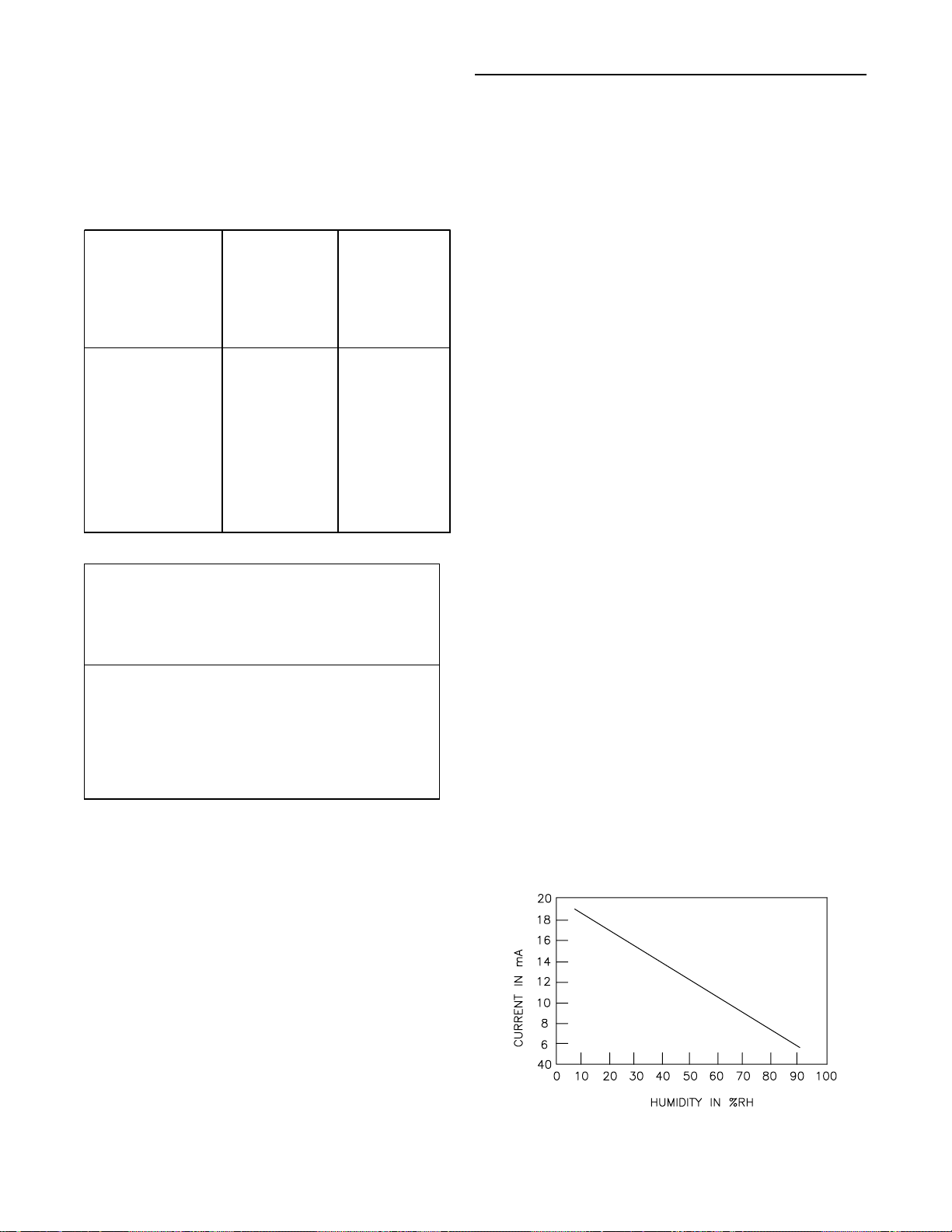
Exhaust/Comparative Enthalpy Module (ECEM Optional 1U52 used on units with Statitrac and/or
comparative enthalpy options)
The Exhaust/Comparative Enthalpy module receives information from the return air humidity sensor, the outside air
humidity sensor, and the return air temperature sensor to
utilize the lowest possible humidity level when considering
economizer operation. In addition, it receives space pressure information which is used to maintain the space pressure to within the setpoint controlband. Refer to the table
below for the Humidity vs Voltage input values.
7
Page 8
General Information (Continued)
TM
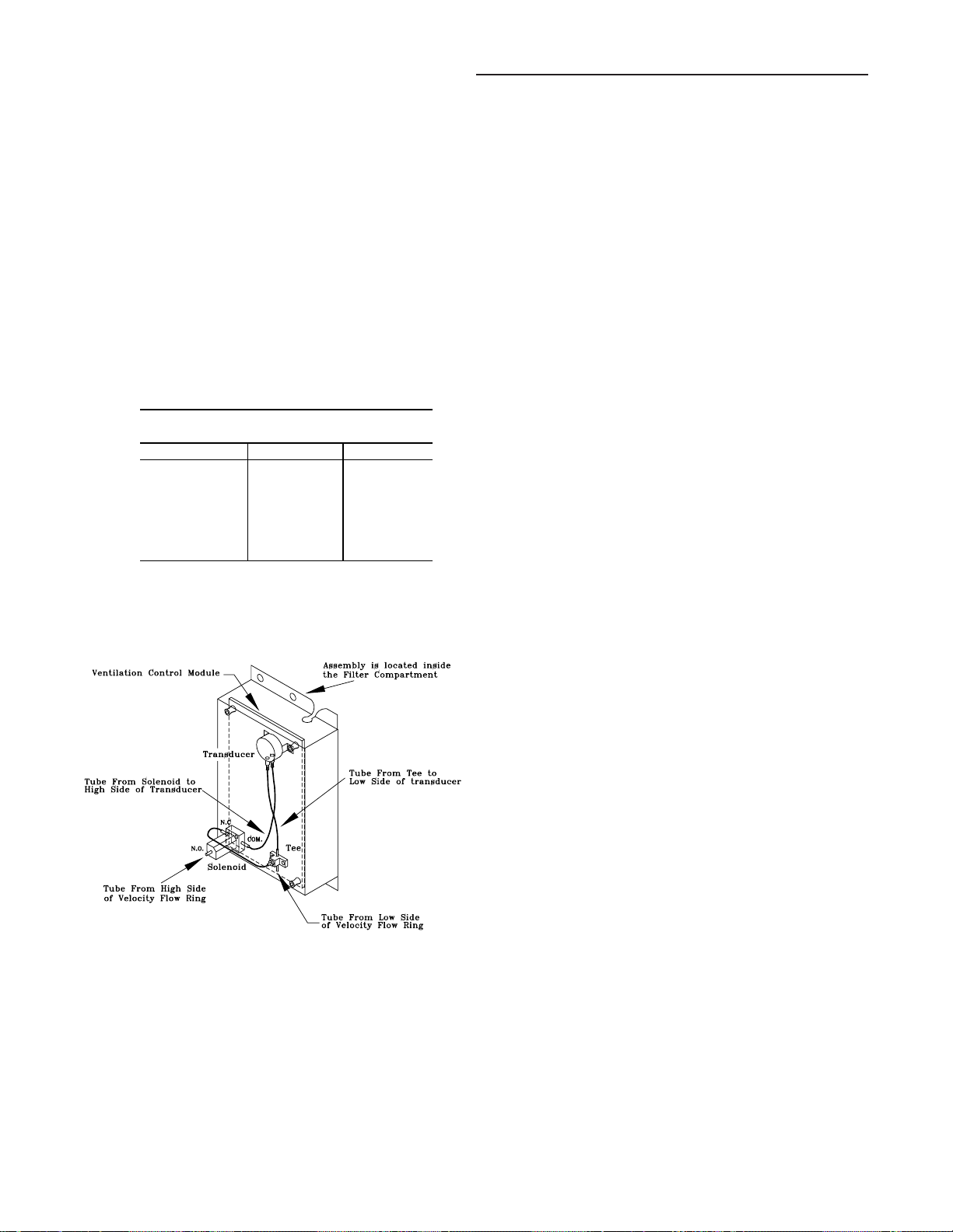
Ventilation Control Module (VCM - Design special
option only)
The Ventilation Control Module (VCM) is located in the filter
section of the unit and is linked to the unit's UCM network.
Using a "velocity pressure" sensing ring located in the fresh
air section, allows the VCM to monitor and control the quantity of fresh air entering the unit to a minimum airflow setpoint.
An optional temperature sensor can be connected to the
VCM which enables it to control a field installed fresh air
preheater.
An optional CO
control CO
CFM upward as the CO
maximum effective (reset) setpoint value for fresh air enter-
sensor can be connected to the VCM to
2
reset. The reset function adjust the minimum
2
concentrations increase. The
2
ing the unit is limited to the systems operating CFM. The
following table lists the Minimum Outside Air CFM vs Input
Voltage.
Minimum Ou tside Air Setpoint
w/VC M Module & T raq
Sensing
Unit Input Volts CFM
20 & 25 Ton 0.5 - 4.5 vdc 0 - 14000
30 Ton 0.5 - 4.5 vdc 0 - 17000
40 Ton 0.5 - 4.5 vdc 0 - 22000
50 & 55 Ton 0.5 - 4.5 vdc 0 - 28000
60 thru 75 Ton 0.5 - 4.5 vdc 0 - 33000
90 thru 130 Ton 0.5 - 4.5 vdc 0 - 46000
The velocity pressure transducer/solenoid assembly is illustrated below. Refer to the "TraqTM Sensor Sequence of Operation" section for VCM operation.
Velocity Pressure Transducer/Solenoid Assembly
For complete application details of the module, refer to Engineering Bulletin RT-EB-109.
Input Devices & System Functions
The descriptions of the following basic Input Devices used
within the UCM network are to acquaint the operator with
their function as they interface with the various modules.
Refer to the unit's electrical schematic for the specific module connections.
Constant V olume & Variable Air Volume Units
Supply Air Temperature Sensor (3RT9)
Is an analog input device used with CV & VAV applications.
It monitors the supply air temperature for; supply air temperature control (VAV), supply air temperature reset (VAV),
supply air temperature low limiting (CV), supply air tempering (CV/VAV). It is mounted in the supply air discharge section of the unit and is connected to the RTM (1U48).
Return Air Temperature Sensor (3RT6)
Is an analog input device used with a return humidity sensor on CV & VAV applications when the compar ative enthalpy option is ordered. It monitors the return air temperature and compares it to the outdoor temperature to establish which temperature is best suited to maintain the cooling
requirements. It is mounted in the return air section and is
connected to the ECEM (1U52).
Evaporator Temperature Sensor (3RT14 and 3RT15)
Is an analog input device used with CV & VAV applications.
It monitors the refrigerant temperature inside the evaporator
coil to prevent coil freezing. It is attached to the suction line
near the evaporator coil and is connected to the SCM/MCM
(1U49). It is factory set for 30 F and has an adjustable
range of 25 F to 35 F. The compressors are staged "Off" as
necessary to prevent icing. After the last compressor stage
has been turned "Off", the compressors will be allowed to
restart once the evaporator temperature rises 10 F above
the "coil frost cutout temperature" and the minimum three
minute "Off" time has elapsed.
Generic Building Automation System Module
(GBAS - Optional 1U51 used with non-Trane building
control systems)
The Generic Building Automation System (GBAS) module
allows a non-Trane building control system to communicate
with the rooftop unit and accepts external setpoints in form
of analog inputs for cooling, heating, supply air pressure,
and a binary Input for demand limit. Refer to the "Field Installed Control Wiring" section for the input wiring to the
GBAS module and the various desired setpoints with the
corresponding DC voltage inputs for both VAV and CV applications.
Filter Switch (3S21)
Is a binary input device used on CV & VAV applications. It
measures the pressure differential across the unit filters. It
is mounted in the filter section and is connected to the RTM
(1U48). A diagnostic SERVICE signal is sent to the remote
panel if the pressure differential across the filters is at least
0.5" w.c.. The contacts will automatically open when the
pressure differential across the filters decrease to 0.4" w.c..
The switch differential can be field adjusted between 0.17"
w.c. to 5.0" w.c. ± 0.05" w.c..
Supply and Exhaust Airflow Proving Switches (3S68
and 3S69)
3S68 is a binary input device used on CV & VAV applications to signal the RTM when the supply fan is operating. It
is located in the supply fan section of the unit and is connected to the RTM (1U48). During a request for fan operation, if the differential switch is detected to be open for 40
consecutive seconds; compressor operation is turned "Off",
heat operation is turned "Off", the request for supply fan operation is turned "Off" and locked out, IGV's (if equipped)
are "closed", exhaust dampers (if equipped) are "closed",
economizer dampers (if equipped) are "closed", and a
manual reset diagnostic is initiated.
8
Page 9

General Information (Continued)
3S69 is a binary input device used on all rooftop units
equipped with an exhaust fan. It is located in the exhaust
fan section of the unit and is connected to the RTM (1U48).
During a request for fan operation, if the differential switch
is detected to be open for 40 consecutive seconds, the
economizer is closed to the minimum position setpoint, the
request for exhaust fan operation is turned "Off" and locked
out, and a manual reset diagnostic is initiated. The fan failure lockout can be reset; at the Human Interface located in
the unit's control panel, by Tracer, or by cycling the control
power to the RTM (1S70 Off/On).
Lead-Lag
Is a selectable mode of operation on 40 thru 130 Ton units
within the Human Interface. It alternates the starting between the first compressor of each refrigeration circuit. Only
the compressor banks will switch, not the order of the compressors within a bank, providing the first compressor in
each circuit had been activated during the same request for
cooling.
Supply and Exhaust Fan Circuit Breakers (1CB1, 1CB2)
The supply fan and exhaust fan motors are protected by circuit breakers 1CB1 and 1CB2 respectively. They will trip
and interrupt the power supply to the motors if the current
exceeds the breaker's "must trip" value. The rooftop module
(RTM) will shut all system functions "Off" when an open fan
proving switch is detected.
Low Pressure Control
Is accomplished using a binary input device on CV & VAV
applications. LP cutouts are located on the suction lines
near the scroll compressors.
The LPC contacts are designed to close when the suction
pressure exceeds 22 ± 4 psig. If the LP control is open
when a compressor is requested to start, none of the compressors on that circuit will be allowed to operate. They are
locked out and a manual reset diagnostic is initiated.
The LP cutouts are designed to open if the suction pressure
approaches 7 ± 4 psig. If the LP cutout opens after a compressor has started, all compressors operating on that circuit will be turned off immediately and will remain off for a
minimum of three minutes.
If the LP cutout trips four consecutive times during the first
three minutes of operation, the compressors on that circuit
will be locked out and a manual reset diagnostic is initiated.
Saturated Condenser Temperature Sensors (2RT1 and
2RT2)
Are analog input devices used on CV & VAV applications
mounted inside a temperature well located on a condenser
tube bend. They monitor the saturated refrigerant temperature inside the condenser coil and are connected to the
SCM/MCM (1U49). As the saturated refrigerant temperature
varies due to operating conditions, the condenser fans are
cycled "On" or "Off" as required to maintain acceptable operating pressures.
denser fans "On". If the operating fans can not bring the
condensing temperature to within the controlband, more
fans are turned on. As the saturated condensing temperature approaches the lower limit of the controlband, fans are
sequenced "Off". The minimum "On/Off" time for condenser
fan staging is 5.2 seconds. If the system is operating at a
given fan stage below 100% for 30 minutes and the saturated condensing temperature is above the "efficiency
check point" setting, a fan stage will be added. If the saturated condensing temperature falls below the "efficiency
check point" setting, the fan control will remain at the
present operating stage. If a fan stage cycles four times
within a 10 minute period, the control switches from controlling to the "lower limit" to a temperature equal to the "lower
limit" minus the "temporary low limit suppression" setting. It
will utilize this new "low limit" temperature for one hour to
reduce condenser fan short cycling.
High Pressure Controls
High Pressure controls are located on the discharge lines
near the scroll compressors. They are designed to open
when the discharge pressure approaches 405 ± 7 psig. The
controls reset automatically when the discharge pressure
decreases to approximately 300 ± 20 psig. However, the
compressors on that circuit are locked out and a manual reset diagnostic is initiated.
Outdoor Air Humidity Sensor (3U63)
Is an analog input device used on CV & VAV applications
with 100% economizer. It monitors the outdoor humidity levels for economizer operation. It is mounted in the fresh air
intake section and is connected to the RTM (1U48).
Return Air Humidity Sensor (3U64)
Is an analog input device used on CV & VAV applications
with the comparative enthalpy option. It monitors the return
air humidity level and compares it to the outdoor humidity
level to establish which conditions are best suited to maintain the cooling requirements. It is mounted in the return air
section and is connected to the ECEM (1U52).
Low Ambient Control
The low ambient modulating output on the compressor
module is functional on all units with or without the low ambient option. When the compressor module has staged up
to it's highest stage (stage 2 or 3 depending on unit size),
the modulating output will be at 100% (10 VDC). When the
control is at stage 1, the modulating output (0 to 10 VDC)
will control the saturated condensing temperature to within
the programmable "condensing temperature low ambient
control point".
Status/Annunciator Output
Is an internal function within the RTM (1U48) module on CV
& VAV applications that provides;
a. diagnostic and mode status signals to the remote
panel (LEDs) and to the Human Interface.
b. control of the binary Alarm output on the RTM.
Head Pressure Control
is accomplished using two saturated refrigerant temperature sensors on CV & VAV applications. Dur ing a request
for compressor operation, when the condensing temperature rises above the "lower limit" of the controlband, the
Compressor Module (SCM/MCM) starts sequencing con-
c. control of the binary outputs on the GBAS module to
inform the customer of the operational status and/or
diagnostic conditions.
9
Page 10
General Information (Continued)
Low Ambient Compressor Lockout
Utilizes an analog input device for CV & VAV applications.
When the system is configured for low ambient compressor
lockout, the compressors are not allowed to operate if the
temperature of the outside air falls below the lockout setpoint. When the temperature rises 5 F above the lockout
setpoint, the compressors are allowed to operate. The setpoint for units without the low ambient option is 50 F. For
units with the low ambient option, the setpoint is 0 F. The
setpoints are adjustable at the Human Interface inside the
unit control panel.
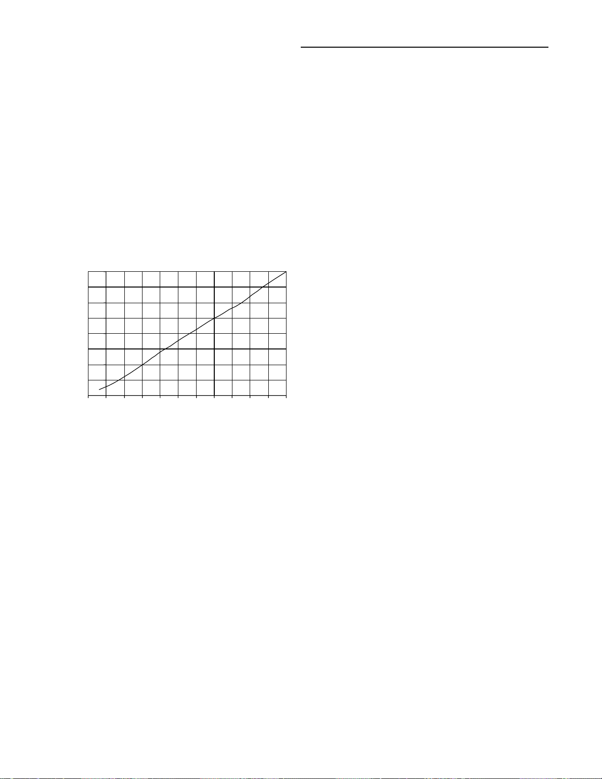
Space Pressure Transducer (3U62)
Is an analog input device used on CV & VAV applications
with the Statitrac option. It modulates the exhaust dampers
to keep the space pressure within the building to a customer designated controlband. It is mounted in the filter
section just above the exhaust damper actuator and is connected to the ECEM (1U52). Field supplied pneumatic tubing must be connected between the space being controlled
and the transducer assembly.
4.0
3.5
3.0
2.5
2.0
Volts
1.5
1.0
0.5
0.0
Transducer Voltage Output vs Pressure Input
-0.5 0.0 0.5 1.0 1.5 2. 0 2.5 3. 0 3.5 4.0 4.5 5.0
P r e ssure ( i nche s w . c. )
Morning W arm-Up - Zone Heat
When a system changes from an unoccupied to an occupied mode, or switches from STOPPED to AUTO, or power
is applied to a unit with the MWU option, the heater in the
unit or external heat will be brought on if the space temperature is below the MWU setpoint. The heat will remain
on until the temperature reaches the MWU setpoint. If the
unit is VAV, then the VAV box/unocc relay will continue to
stay in the unoccupied position and the VFD/IGV output
will stay at 100% during the MWU mode. When the MWU
setpoint is reached and the heat mode is terminated, then
the VAV box/unocc relay will switch to the occupied mode
and the VFD/IGV output will be controlled by the duct static
pressure. During Full Capacity MWU the economizer
damper is held closed for as long as it takes to reach
setpoint. During Cycling Capacity MWU the economizer
damper is allowed to go to minimum position after one
hour of operation if setpoint has not been reached.
Compressor Motor Winding Thermostats (2B7S1,
2B17S2, 2B27S5, 2B8S3, 2B18S4 & 2B28S6)
A thermostat is embedded in the motor windings of each
Scroll compressor. Each thermostat is designed to open if
the motor windings exceeds approximately 221 F. The thermostat will reset automatically when the winding temperature decreases to approximately 181 F. Rapid cycling, loss
of charge, abnormally high suction temperatures, or the
compressor running backwards could cause the thermostat
to open. During a request for compressor operation, if the
Compressor Module (SCM) detects a problem outside of
it's normal parameters, it turns any operating
compressor(s) on that circuit "Off", locks out all compressor
operation for that circuit, and initiates a manual reset diagnostic.
Supply Air T emperature Lo w Limit
Uses the supply air temperature sensor input to modulate
the economizer damper to minimum position in the event
the supply air temperature falls below the occupied heating
setpoint temperature.
Freezestat (4S12)
Is a binary input device used on CV & VAV units with Hydronic Heat. It is mounted in the heat section and connected to the Heat Module (1U50). If the temperature of the
air entering the heating coil falls to 40 F, the normally open
contacts on the freezestat closes signalling the Heat Module (1U50) and the Rooftop Module (RTM) to:
a. drive the Hydronic Heat Actuator (4U15) to the full
open position.
b. turn the supply fan "Off".
c. closes the outside air damper;
d. turns "On" the SERVICE light at the Remote Panel.
e. initiates a "Freezestat" diagnostic to the Human
Interface.
High Duct Temp Thermostats (Optional 3S16, 3S17)
Are binary input devices used on CV & VAV applications
with a Trane Communication Interface Module (TCI). They
provide "high limit" shutdown of the unit and requires a
manual reset. They are factory set to open if the supply air
temperature reaches 240 F, or the retur n air temperature
reaches 135 F. Once tripped, the thermostat can be reset
by pressing the button located on the sensor once the air
temperature has decreased approximately 25 F below the
cutout point.
Compressor Circuit Breakers (1CB8, 1CB9, 1CB10,
1CB11 & 1CB14, 1CB15, 1CB16, 1CB17)
The Scroll Compressors are protected by circuit breakers
which interrupt the power supply to the compressors if the
current exceeds the breakers “must trip” value. During a request for compressor operation, if the Compressor Module
(SCM) detects a problem outside of it's normal parameters,
it turns any operating compressor(s) on that circuit "Off",
locks out all compressor operation for that circuit, and initiates a manual reset diagnostic.
Constant Volume (CV) Units
Zone T emperature - Cooling
Relies on input from a sensor located directly in the space,
while a system is in the occupied "Cooling" mode. It modulates the economizer (if equipped) and/or stages the mechanical cooling "On and Off" as required to maintain the
zone temperature to within the cooling setpoint deadband.
Zone Temperature - Heating
Relies on input from a sensor located directly in the space,
while a system is in the occupied "Heating" mode or an unoccupied period, to stage the heat "on and off" or to modulate the heating valve (hydronic heat only) as required to
maintain the zone temperature to within the heating setpoint
deadband. The supply fan will be requested to operate any
time there is a requested for heat. On gas heat units, the
fan will continue to run for 60 seconds after the furnace is
turned off.
Supply Air T empering
On CV units equipped with staged heat, if the supply air
temperature falls 10 F below the occupied heating setpoint
temperature while the heater is "Off", the first stage of heat
will be turned "On". The heater is turned "Off" when the supply air temperature reaches 10 F above the occupied heating setpoint temperature.
10
Page 11
General Information (Continued)
Variable Air Volume (VAV) Units
Occupied Heating - Supply Air Temperature
When a VAV units is equipped with "Modulating Heat", and
the system is in an occupied mode, and the field supplied
changeover relay contacts (5K87) have closed, the supply
air temperature will be controlled to the customer specified
supply air heating setpoint. It will remain in the heating status until the changeover relay contacts are opened.
Occupied Cooling - Supply Air T emperature
When a VAV unit is in the occupied mode, the supply air
temperature will be controlled to the customers specified
supply air cooling setpoint by modulating the economizer
and/or staging the mechanical cooling "On and Off" as required. The changeover relay contacts must be open on
units with "Modulating Heat" for the cooling to operate.
Daytime Warm-up
On VAV units equipped with heat, if the zone temperature
falls below the daytime warm-up initiate temperature during the occupied mode, the system will switch to full airflow. Dur ing this mode, the VAV box/unocc relay, RTM K3,
will be energized (this is to signal the VAV boxes to go to
100%). After the VAV box max stroke time has elapsed
(factory set at 6 minutes), the VFD/IGV output will be set to
100%. The airflow will be at 100% and the heat will be
turned on to control to the occupied heating setpoint.
When the zone temperature reaches the daytime warm-up
termination setpoint, the heat will be turned off, the K3 relay will be de-energized, releasing the VAV boxes, the
VFD/IGV output will go back to duct static pressure control
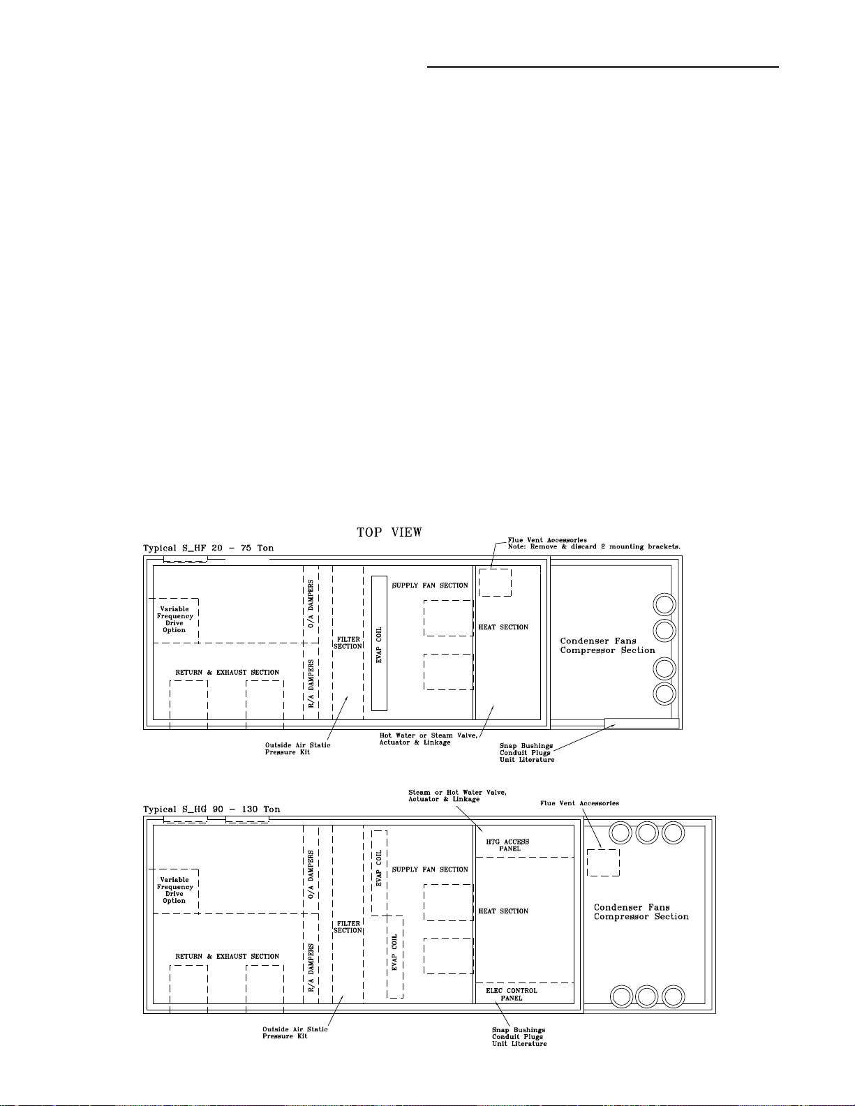
Unit Component Layout and "Shipwith" Locations
and the unit will return to discharge air control. If the occ
zone heating setpoint is less than the DWU terminate
setpoint, the heat will turn off when the occ zone heat
setpoint is reached, but it will stay in DWU mode and cycle
the heat to maintain setpoint.
Unoccupied Heating - Zone Temperature
When a VAV unit is equipped with gas, electric, or hydronic
heat and is in the unoccupied mode, the zone temperature
will be controlled to within the customers specified setpoint
deadband. During an unoccupied mode for a VAV unit, the
VAV box/unocc relay will be in the unoccupied position and
the VFD/IGV output will be at 100%. This means that if
there is a call for heat (or cool) and the supply fan comes
on, it will be at full airflow and the VAV boxes in the space
will need to be 100% open as signaled by the VAV box/
unocc relay.
Supply Air T empering
On VAV units equipped with "Modulating Heat", if the supply air temperature falls 10
ture setpoint, the hydronic heat valve will modulate to
maintain the supply air temperature to within the low end
of the setpoint deadband.
Supply Duct Static Pressure Control (Occupied)
The RTM relies on input from the duct pressure transducer
when a unit is equipped with Inlet Guide Vanes or a Variable Frequency Drive to position the Inlet Guide Vanes or
set the supply fan speed to maintain the supply duct static
pressure to within the static pressure setpoint deadband.
Refer to the Transducer Voltage Output vs Pressure Input
values listed in the Space Pressure Transducer (3U62)
section.
F below the supply air tempera-
11
Page 12
General Information (Continued)
RTM
1U48
J1-1
J2-1
SCM
1U49
Bracke
Heat MOD
1U50
Mounting
Plate
LCI MOD
1U54
TCI MOD
1U54
Bracke
J2-1
J1-1
OR
1PCB MOD
1U55
ECEM
1U52
VOM
1U53
GBAS MOD
1U51
J1-1
J2-1
1TB9
J2-1
J1-1
J2-1
J1-1
J2-1
J1-1
J1-1
J2-1
Bracke
Bracke
Bracke
Bracke
Mounting
Plate
Mounting
Plate
RTM
1U48
J1-1
J2-1
SCM
1U49
GBAS MOD
1U51
J2-1
J1-1
Bracke
Bracke
Bracke
Bracke
Bracke
Bracke
VOM
1U53
Mounting
Plate
J1-1
J2-1
Heat MOD
1U50
Mounting
Plate
LCI MOD
1U54
TCI MOD
1U54
OR
1PCB MOD
1U55
ECEM
1U52
J1-1
1TB9
J2-1
J1-1
J2-1
J1-1
J1-1
J2-1
J2-1
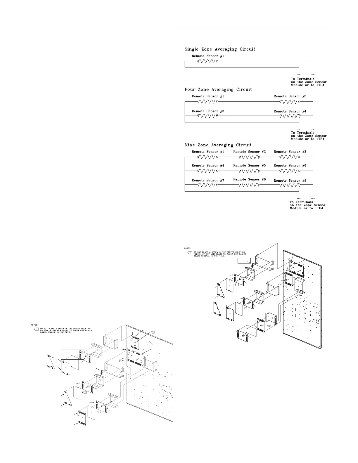
Space Temperature Avera ging
Space temperature averaging for Constant Volume applications is accomplished by wiring a number of remote sensors
in a series/parallel circuit.
The fewest number of sensors required to accomplish
space temperature averaging is four. Figure 8 illustrates a
single sensor circuit (Single Zone), four sensors wired in a
series/parallel circuit (Four Zone), nine sensors wired in a
series/parallel circuit (Nine Zone). Any number squared, is
the number of remote sensors required.
Wiring termination will depend on the type of remote panel
or control configuration for the system. Refer to the wiring
diagrams that shipped with the unit.
Space Temperature Averaging with Multiple Sensors
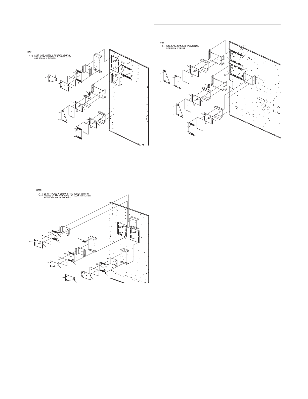
Unit Control Modules (UCM)
Unit control modules are microelectronic circuit boards designed to perform specific unit functions. These modules
through Proportional/Integral control algorithms provide the
best possible comfort level for the customer. They are
mounted in the control panel and are factory wired to their
respective internal components. They receive and interpret
information from other unit modules, sensors, remote panels, and customer binary contacts to satisfy the applicable
request for economizing, mechanical cooling, heating, and
ventilation. Figure 9 below illustrates the typical location of
each "1U" designated module.
Control Module Locations for S_HF 20 & 25 Ton Units
SCM
J2-1
t
1U49
J1-1
TCI MOD
1U54
J2-1
J1-1
OR
LCI MOD
1U54
1PCB MOD
1U55
J2-1
J1-1
Mounting
Plate
Heat MOD
1U50
J1-1
VOM
1U53
J2-1
J1-1
ECEM
1U52
Mounting
Plate
Bracke
1TB9
Bracke
J1-1
t
Bracke
t
J2-1
GBAS MOD
1U51
Mounting
Plate
Bracke
t
J2-1
J1-1
t
Bracke
J2-1
RTM
1U48
Bracke
Control Module Locations for S_HF 30 Ton Units
J2-1
RTM
Bracke
1U48
t
1PCB MOD
1U55
J2-1
J1-1
TCI MOD
1U54
OR
LCI MOD
1U54
J1-1
Mounting
Plate
J1-1
ECEM
1U52
J1-1
VOM
1U53
1TB9
Heat MOD
1U50
Mounting
Plate
J1-1
J2-1
t
Bracke
t
Bracke
SCM
1U49
J1-1
Bracke
t
t
Bracke
t
Bracke
J2-1
J2-1
GBAS MOD
1U51
J2-1
J1-1
J2-1
t
12
Page 13
General Information (Continued)
RTM
1U48
GBAS MOD
1U51
Bracke
VOM
1U53
Mounting
Plate
Heat MOD
1U50
LCI MOD
1U54
TCI MOD
1U54
OR
1PCB MOD
1U55
ECEM
1U52
1TB9
MCM
1U49
Bracke
Bracke
Bracke
Bracke
Bracke
Mounting
Plate
Mounting
Plate
J2-1
J1-1
J1-1
J2-1
J2-1
J1-1
J1-1
J2-1
J2-1
J1-1
J2-1
J1-1
J2-1
J1-1
GBAS MODGBAS MOD
1U511U51
BrackeBracket
VOMVOM
1U531U53
J1-1J1-1
J2-1J2-1
MountingMounting
PlatePlate
J2-1J2-1
J1-1J1-1
BrackeBracket
Bracke
Bracket
1PCB MOD1PCB MOD
1U551U55
ECEMECEM
1U521U52
1TB91TB9
J2-1J2-1
J1-1J1-1
J1-1J1-1
J2-1J2-1
MountingMounting
PlatePlate
MountingMounting
PlatePlate
J1-1J1-1
J2-1J2-1
J2-1J2-1
J1-1J1-1
Heat MODHeat MOD
1U501U50
LCI MODLCI MOD
1U541U54
TCI MODTCI MOD
1U541U54
OROR
BrackeBracket
Bracke
Bracket
J2-1J2-1
J1-1J1-1
RTMRTM
1U481U48
MCMMCM
1U491U49
J1-1J1-1
J2-1J2-1
J1-1J1-1
J2-1J2-1
GBAS MOD
1U51
Bracke
VOM
1U53
Mounting
Plate
1PCB MOD
1U55
ECEM
1U52
1TB9
Bracke
Mounting
Plate
Mounting
Plate
Heat MOD
1U50
LCI MOD
1U54
TCI MOD
1U54
OR
J1-1
J2-1
J1-1
J2-1
J2-1
J1-1
J2-1
J1-1
J2-1
J1-1
J1-1
J2-1
Bracke
Bracke
Bracke
Bracke
RTM
1U48
MCM
1U49
J1-1
J2-1
Control Module Locations for S_HF 40, 60, 70 &
75 Ton Units
MCM
1U49
Bracke
t
J1-1
TCI MOD
1U54
J2-1
J1-1
OR
J1-1
LCI MOD
1U54
J2-1
Mounting
Plate
1PCB MOD
1U55
Heat MOD
1U50
J2-1
J2-1
J1-1
Mounting
Plate
J2-1
J1-1
Bracke
J1-1
ECEM
1U52
VOM
1U53
1TB9
Bracke
t
J2-1
J1-1
t
Bracke
Mounting
Plate
Bracke
t
J2-1
GBAS MOD
1U51
t
Bracke
Control Module Locations for S_HF 50 & 55 Ton Units
RTM
1U48
t
Control Module Locations for S_HG 90 - 130 Ton Units
Bracke
RTM
Bracke
J1-1
J2-1
1U48
Bracke
t
Bracke
Mounting
Plate
J1-1
J2-1
J2-1
TCI MOD
1U54
J1-1
t
ECEM
1U52
Bracke
OR
1TB9
t
J1-1
J2-1
LCI MOD
1U54
J1-1
J2-1
Bracke
Mounting
Plate
t
Heat MOD
1U50
J2-1
GBAS MOD
1U51
Mounting
Plate
VOM
1U53
J1-1
J2-1
1PCB MOD
1U55
J1-1
t
t
MCM
1U49
13
Page 14

Table of Contents
Section One
About The Manual ............................................................... 2
Literature Change History ................................................ 2
Overview of Manual ......................................................... 2
Section Two
General Information ............................................................. 4
Model Number Description .............................................. 4
Hazard Identification ........................................................ 6
Commonly Used Acronyms ............................................. 6
Unit Description ................................................................ 6
Input Devices & System Functions .................................. 8
Constant Volume & Variable Air Volume Units ................ 8
Constant Volume (CV) Units .......................................... 10
Variable Air Volume (VAV) Units .................................... 11
Space Temperature Averaging .......................................12
Unit Control Modules (UCM) ..........................................12
Section Three
Installation .......................................................................... 14
Unit Inspection ............................................................... 14
Storage ........................................................................... 14
Unit Clearances .............................................................14
Unit Dimensions & Weight Information .......................... 14
Roof Curb and Ductwork ............................................... 22
Pitch Pocket Location .................................................... 23
Unit Rigging & Placement .............................................. 23
General Unit Requirements ........................................... 25
Main Electrical Power Requirements............................. 25
Field Installed Control Wiring ......................................... 25
Requirements for Electric Heat Units ............................ 25
Requirements for Gas Heat ...........................................25
Requirements for Hot Water Heat (SLH_) ..................... 25
Requirements for Steam Heat (SSH_) .......................... 26
O/A Pressure Sensor and Tubing Installation ............... 26
Condensate Drain Connection....................................... 27
Shipping Fasteners ........................................................27
O/A Sensor & Tubing Installation ...................................31
Units with Statitrac™; .................................................... 31
Gas Heat Units (SFH_) ..................................................32
Connecting the Gas Supply Line to the Furnace
Gas Train ........................................................................32
Flue Assembly Installation ............................................. 34
Hot Water Heat Units (SLH_) ........................................ 34
Steam Heat Units (SSH_) ..............................................35
Disconnect Switch External Handle ............................... 38
Electric Heat Units (SEH_) ............................................ 38
Main Unit Power Wiring ................................................. 38
Disconnect Switch Sizing (DSS) ....................................44
Field Installed Control Wiring ......................................... 45
Controls using 24 VAC ................................................... 45
Controls using DC Analog Input/Outputs ....................... 45
Constant Volume System Controls ................................45
Variable Air Volume System Controls ............................ 46
Constant Volume or Variable Air Volume System
Controls ..........................................................................46
Section Four
Unit Start-Up ......................................................................55
Cooling Sequence of Operation .................................... 55
Gas Heating Sequence of Operation ............................. 56
Fenwal Ignition System .................................................. 56
Honeywell Ignition System ............................................. 56
Modulating Gas Sequence of Operation ....................... 57
Flame Failure ................................................................. 57
Electric Heat Sequence of Operation ............................ 58
Wet Heat Sequence of Operation.................................. 58
Electrical Phasing .......................................................... 59
Voltage Supply and Voltage Imbalance ......................... 60
Service Test Guide for Component Operation ............... 61
Verifying Proper Fan Rotation ....................................... 63
If all of the fans are rotating backwards;........................ 63
System Airflow Measurements ...................................... 63
Constant Volume Systems............................................. 63
Variable Air Volume Systems ......................................... 65
Exhaust Airflow Measurement ....................................... 66
TraqTM Sensor Airflow Measurement ........................... 66
Economizer Damper Adjustment ................................... 80
Compressor Start-Up .....................................................82
Compressor Operational Sounds .................................. 83
Thermostatic Expansion Valves..................................... 93
Charging by Subcooling ................................................. 93
Low Ambient Dampers ................................................... 93
Electric, Steam and Hot Water Start-Up ........................ 94
Gas Furnace Start-Up .................................................... 94
Two Stage Gas Furnace ................................................ 95
Full Modulating Gas Furnace......................................... 97
Limited Modulating Gas Furnace ................................... 98
Final Unit Checkout ........................................................ 99
Section Five
Service & Maintenance.................................................... 100
Fan Belt Adjustment ..................................................... 104
Scroll Compressor Replacement ................................. 105
VFD Programming Parameters ................................... 106
Monthly Maintenance ................................................... 107
Filters............................................................................ 107
Cooling Season ............................................................107
Heating Season............................................................ 108
Coil Cleaning ................................................................ 108
Final Process ............................................................... 109
Index ............................................................................... 111
UV ................................................................................... 114
Warranty ......................................................................... 114
Page 15
Installation
Unit Inspection
As soon as the unit arrives at the job site
[ ] Verify that the nameplate data matches the data on the
sales order and bill of lading (including electrical data).
[ ] Verify that the power supply complies with the unit name-
plate specifications.
[ ] Verify that the power supply complies with the electric
heater specifications on the uit nameplate.
[ ] Visually inspect the exterior of the unit, including the roof,
for signs of shipping damage.
[ ] Check for material shortages. Refer to the Component
Layout and Shipwith Location illustration.
If the job site inspection of the unit reveals damage or material shortages, file a claim with the carrier immediately.
Specify the type and extent of the damage on the "bill of
lading" before signing.
[ ] Visually inspect the internal components for shipping
damage as soon as possible after delivery and before it
is stored. Do not walk on the sheet metal base pans.
Storage
Ta ke precautions to prevent condensate from forming inside
the unit’s electrical compartments and motors if:
a. the unit is stored before it is installed; or,
b. the unit is set on the roof curb, and temporary heat is
provided in the building. Isolate all side panel service
entrances and base pan openings (e.g., conduit
holes, S/A and R/A openings, and flue openings)
from the ambient air until the unit is ready for startup.
Note: Do not use the unit's heater for temporary
heat without first completing the startup procedure
detailed under "Starting the Unit".
Trane will not assume any responsibility for
equipment damage resulting from condensate accumulation
on the unit's electrical and/or mechanical components.
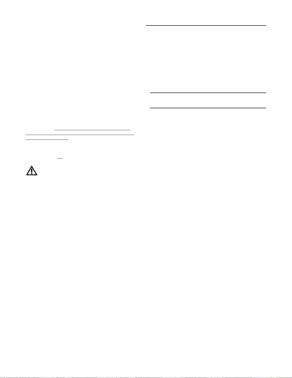
Unit Clearances
Figure 3-1 illustrates the minimum operating and service
clearances for either a single or multiple unit installation.
These clearances are the minimum distances necessary to
assure adequate serviceability, cataloged unit capacity, and
peak operating efficiency.
WARNING
No Step Surface!
FOR ACCESS TO COMPONENTS, THE BASE SHEET
METAL SURFACE MUST BE REINFORCED.
Bridging between the unit's main supports may consist
of multiple 2 by 12 boards or sheet metal grating.
Failure to comply could result in death or severe
personal injury from falling.
[ ] If concealed damage is discovered, notify the carrier's
terminal of damage immediately by phone and by mail.
Concealed damage must be reported within 15 days.
Request an immediate joint inspection of the damage by
the carrier and the consignee. Do not remove damaged
material from the receiving location. Take photos of the
damage, if possible. The owner must provide reasonable
evidence that the damage did not occur after delivery.
[ ] Remove the protective plastic coverings that shipped
over the compressors.
Providing less than the recommended clearances may result in condenser coil starvation, "short-circuiting" of exhaust and economizer airflows, or recirculation of hot condenser air.
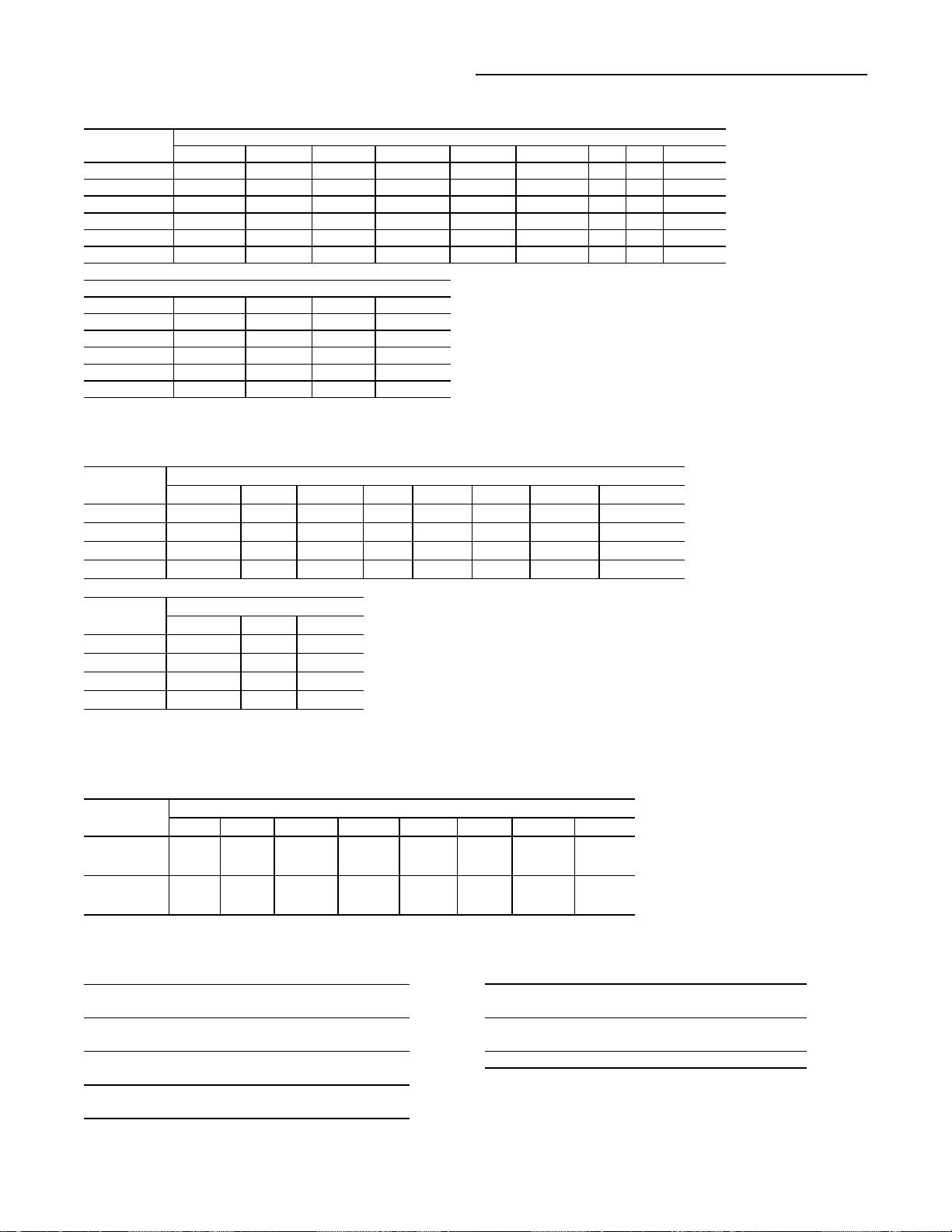
Unit Dimensions & Weight Information
Overall unit dimensional data for a SAHF (20 thru 75 Ton)
cooling only unit is illustrated in Figure 3-2A. Tables 3-1A,
3-1B, and 3-1C list the dimensions. Dimensional data for
SEH_, SFH_, SLH_, SSH_, and SXH_ (20 thru 130 Ton)
units are illustrated in Figure 3-2B. Tables 3-2A, 3-2B, and
3-2C list the dimensions for the 20 thru 75 Ton units. Dimensions for 90 through 130 Ton units are listed on the illustration in Figure 3-2C.
A Center-of-Gravity illustration and the dimensional data is
shown in Figure 3-3.
Table 3-3 list the typical unit and curb operating weights.
Weights shown represent approximate operating weights.
Actual weights are stamped on the unit nameplate.
14
Page 16
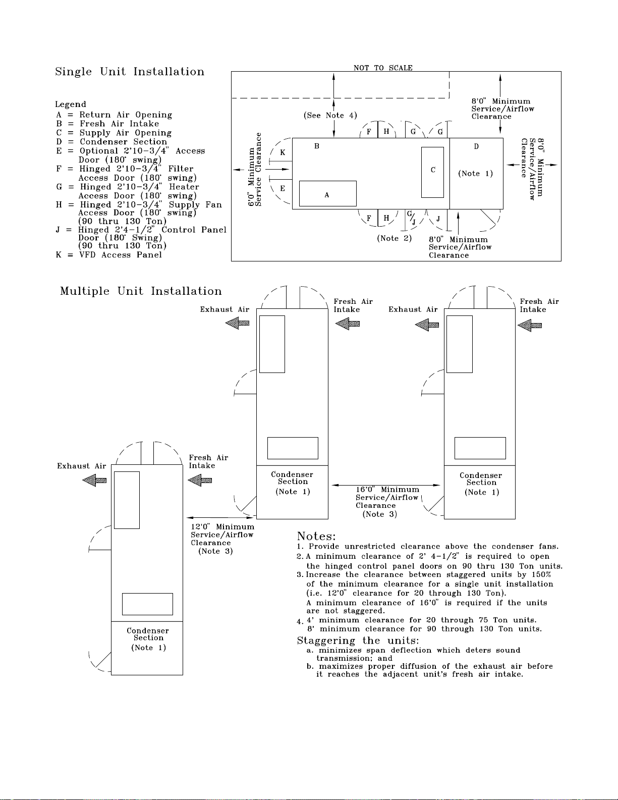
Figure 3-1
Minimum Operation and Service Clearances for Single & Multiple Unit Installation
15
Page 17
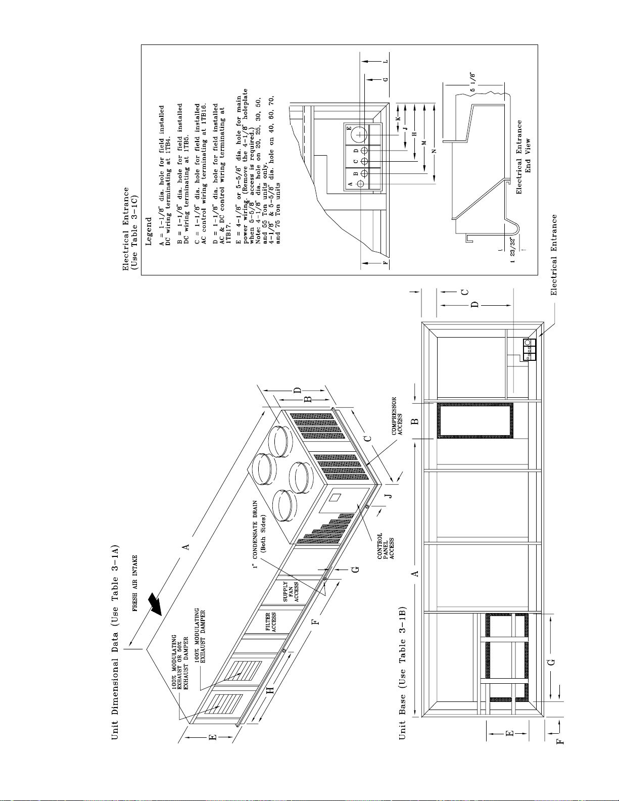
Figure 3-2A
SAHF Cooling-Only Units (20 thru 75 Ton)
16
Page 18

Installation (Continued)
Table 3-1A
Unit Dimensional Data
Unit Dimensions
Size ABCDEFGHJ
20 & 25 Ton 21'-9 3/4" 5'-3 1/8" 7'-6 1/2" 5'-8 15/16" 3'-9 5/16" 12'-6" 1" 7' 1'-3 1/2"
30 Ton 21'-9 3/4" 5'-8 5/8" 7'-6 1/2" 6'-2 7/16" 4'-9 5/16" 12'-6" 1" 7' 1'-3 1/2"
40 Ton 27'-0" 6'-1 5/8" 7'-6 1/2" 6'-7 3/8" 5'-9 5/16" 15'-11 1/8" 1" 8' 2'-5"
50 & 55 Ton 29'-8" 5'-3 1/8" 7'-6 1/2" 5'-8 7/8" 6'-9 5/16" 15'-11 1/8" 1" 8' 2'-5"
60 Ton 27'-0" 6'-1 5/8" 9'-8" 6'-7 3/8" 5'-9 5/16" 15'-11 1/8" 1" 8' 2'-5"
70 & 75 Ton 27'-0" 6'-1 5/8" 9'-8" 6'-7 3/8" 5'-9 5/16" 15'-11 1/8" 1" 8' 1'-4"
Table 3-1B
Unit Base Dimensional Data
Unit Dimensions
Size A BCDEFG
20 - 30 Ton
40 - 55 Ton
60 Ton 16'-7 13/16" 2'-5" 1'-4 9/16" 6'-10 7/8" 4'-5 3/8" 5 13/16" 7'-8 3/16"
70 - 75 Ton
14'-0 1/4" 2'-2 1/2" 11 3/4" 5'-7" 3'-4 3/8" 5 13/16" 6'-6 15/16"
16'-7 13/16" 2'-5" 11 3/4" 5'-7" 3'-4 3/8" 5 13/16" 7'-8 3/16"
16'-7 13/16" 2'-5" 1'-4 9/16" 6'-10 7/8" 4'-5 3/8" 5 13/16" 7'-8 3/16"
Table 3-1C
Electrical Entrance Data
Unit Dimens ions
Size F G H J K L M N
20, 25, & 30 8 7/32" 6 31/32" 15 21/32" 13 21/32" 9 17/32" 8 1/2" 18 1/16" 19 9/16"
50 & 55 Ton
40, 60, 70 8 3/4" 7 3/4" 17 7/8" 15 7/8" 9 29/32" 10 1/16" 20 13/32" 22 5/32"
& 75 Ton
17
Page 19
Figure 3-2B
SEHF, SFHF, SLHF, SSHF, SXHF Units (20 thru 75 Ton)
18
Page 20
Installation (Continued)
g
g
Table 3-2A
Unit Dimensional Data
Unit Dimensions
SizeABCDEFGHJ
20 & 25 Ton 24'-1 3/8" 5'-3 1/8" 7'-6 1/2" 5'-8 15/16" 3'-9 5/16" 13'-3" 1" 7' 1'-3 1/2"
30 Ton 24'-1 3/8" 5'-8 5/8" 7'-6 1/2" 6'-2 3/8" 4'-9 5/16" 13'-3" 1" 7' 1'-3 1/2"
40 Ton 30'-2 1/2" 6'-1 5/8" 7'-6 1/2" 6'-7 3/8" 5'-9 5/16" 15'-11 1/8" 1" 8' 2'-5"
50 & 55 Ton 32'-10 1/2" 5'-3 1/8" 7'-6 1/2" 5'-8 7/8" 6'-9 5/16" 15'-11 1/8" 1" 8' 2'-5"
60 Ton 30'-2 1/2" 6'-1 5/8" 9'-8" 6'-7 3/8" 5'-9 5/16" 15'-11 1/8" 1" 8' 2'-5"
70 & 75 Ton 30'-2 1/2" 6'-1 5/8" 9'-8" 6'-7 3/8" 5'-9 5/16" 15'-11 1/8" 1" 8' 1'-4"
Dimensions
KLMNO
16'-7" 16'-6" 8 1/8" 6 1/4" 9"
16'-7" 16'-6" 8 1/8" 6 1/4" 9"
19'-7" See Note 8 1/8" 6 1/4" 9"
19'-7" See Note 8 1/8" 6 1/4" 9"
19'-7" See Note 8 1/8" 6 1/4" 9"
Note:
19'-6" for SFHF "Low Heat" units or 20'-3" for SFHF "Hi
h Heat" units.
Table 3-2B
Unit Base Dimensional Data
Unit Dimensions
Size A B C D E F G H
20 - 30 Ton 16'-3 3/16" 2'-2 1/2" 5 13/16" 5'-7" 3'-4 3/8" 5 13/16" 6'-6 15/16" 15'-5 5/16"
40 - 55 Ton 19'-10 5/16" 2'-5" 7 1/16" 5'-7" 3'-4 3/8" 5 13/16" 7'-8 3/16" 18'-11 11/16"
60 Ton 19'-10 5/16" 2'-5" 6 1/16" Note 1 4'-5 3/8" 5 13/16" 7'-8 3/16" 18'-11 11/16"
70 - 75 Ton 19'-10 5/16" 2'-5" 6 1/16" Note 1 4'-5 3/8" 5 13/16" 7'-8 3/16" 18'-11 11/16"
Unit Dimensions
Size J K L
20 - 30 Ton 16'-9 3/4" 8 13/16" 9 1/16"
40 - 55 Ton 20'-1 3/4" 8 3/16" 9 1/16"
60 Ton 20'-1 3/4" 8 3/16" 9 1/16"
70 - 75 Ton 20'-1 3/4" 8 3/16" 9 1/16"
Note:
1. 5'-5 15/16" for SEHF units or 7'-8 1/2" for SFHF, SLHF, SSHF, SXHF units.
Table 3-2C
Electrical Entrance Data
Unit Dimensions
Size F G H J K L M N
20, 25, & 30 8 7/32" 6 31/32" 15 21/32" 13 21/32" 9 17/32" 8 1/2" 18 1/16" 19 9/16"
50 & 55 Ton
40, 60, 70 8 3/4" 7 3/4" 17 7/8" 15 7/8" 9 29/32" 10 1/16" 20 13/32" 22 5/32"
& 75 Ton
Table 3-2D
CPVC Dimensional Data
Unit Size Furnace Dimensions (Note) Unit Size Furnace Dimensions (Note)
Size/MBH Length Height Size/MBH Length Height
20 & 25 Ton Low = 235 195-5/32" 9-5/32" 50 - 75 Ton Low = 500 240-1/8" 9-5/32"
High = 500 195-5/32" 9-5/32" High = 850 231-1/8" 9-5/32"
30 Ton Low = 350 195-5/32" 9-5/32" 90 -130 Ton 1000 267-3/16" 10-11/32"
High = 500 195-5/32" 9-5/32"
40 Ton Low = 350 240-1/8" 9-5/32" end of the unit. The height dimension is
High = 850 231-1/8" 9-5/32" from the bottom of the unit base rail.
Note:
The len
th dimension is from the exhaust
19
Page 21
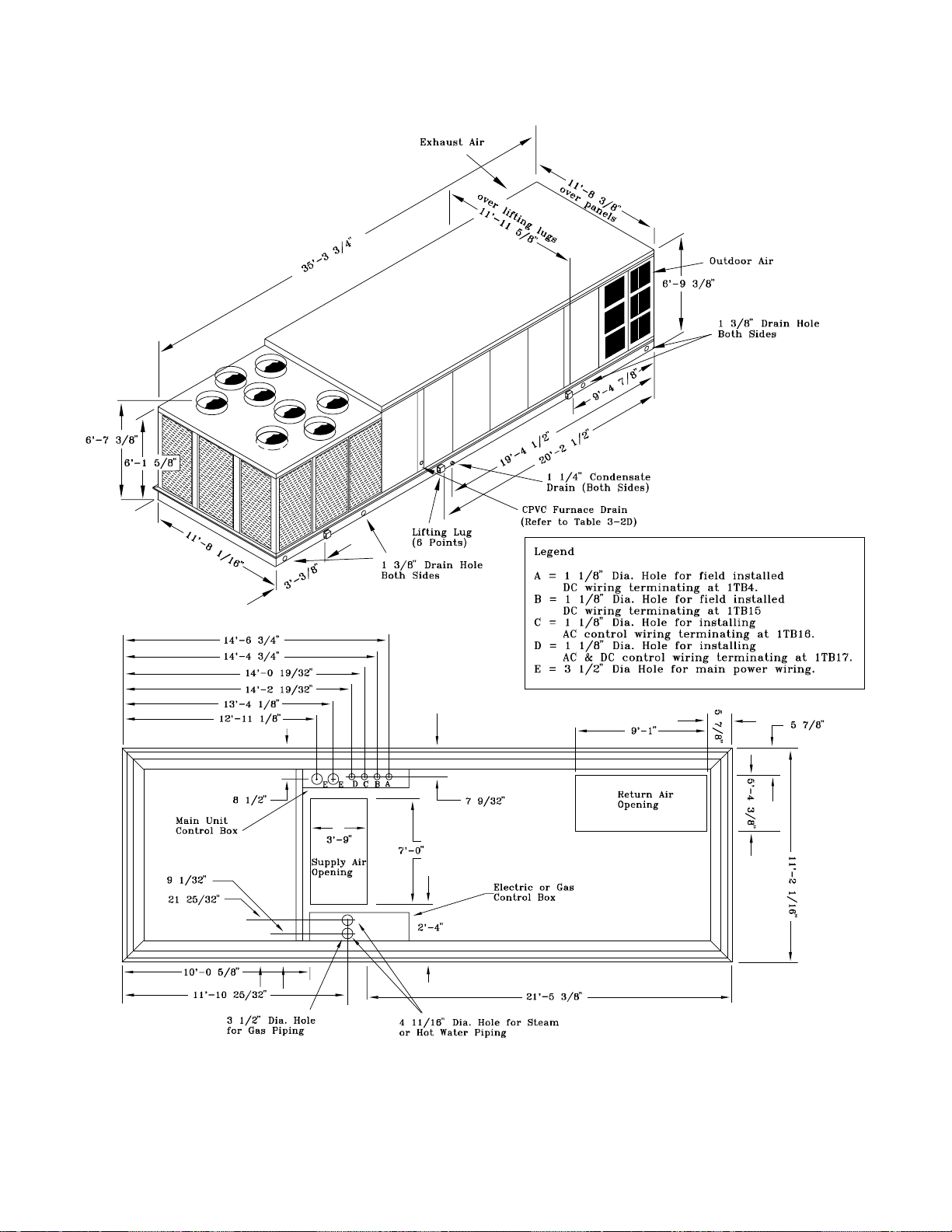
Figure 3-2C
S_HG Cooling & Heating Units (90 through 130 Ton)
20
Page 22
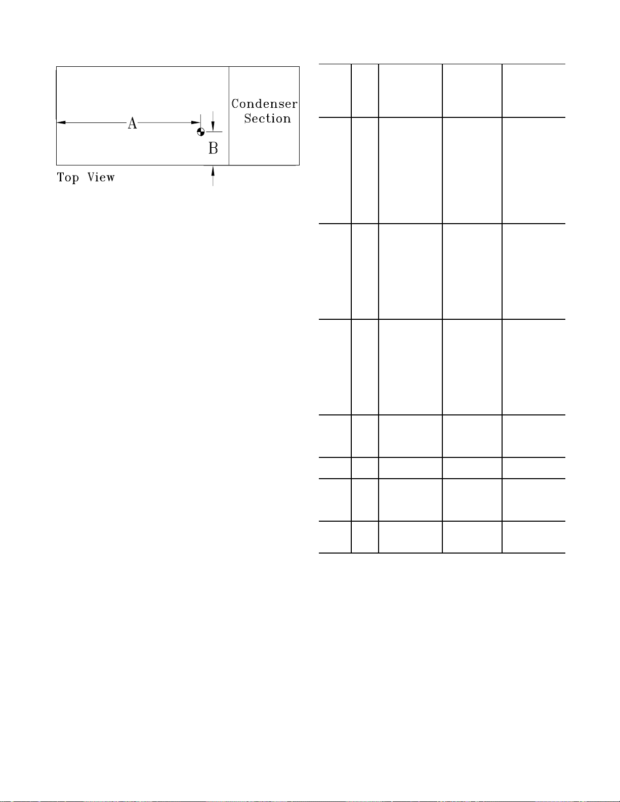
D
BABAB
F
F
F
F
F
F
Figure 3-3
Center-of-Gravity Data (See Note 1)
Units with Units Units
100% without with Supply &
E xhaust Fan Exhau st Fan Exh au st V F
Unit Unit Dim. Dim. Dim. Dim. Dim. Dim.
Model Size A
SAH
SEH
SLH
SSH
SXH
SFH
SXHG,
SEHG,
SLHG,
SSHG
SFHG
SXHG,
SEHG,
SLHG,
SSHG
SFHG
C20 12' 6" 3' 8" 13' 5" 3' 10" 11' 10" 3' 9"
C25 12' 9" 3' 8" 13' 7" 3' 10" 12' 0" 3' 9"
C30 12' 5" 3' 8" 13' 3" 3' 10" 11' 9" 3' 9"
C40 15' 7" 3' 10" 16' 9" 4' 0" 14' 10" 3' 1 1"
C50 16' 7" 3' 10" 17' 9" 4' 0" 15' 8" 3' 1 1"
C55 16' 10" 3' 10" 18' 1" 4' 0" 16' 0" 3' 11"
C60 15' 7" 4' 7" 16' 11" 4' 10" 14' 10" 4' 8"
C70 15' 10" 4' 8" 17' 1" 4' 10" 15' 2" 4' 9"
C75 15' 11" 4' 8" 17' 2" 4' 10" 15' 2" 4' 9"
C20 13' 8" 3' 8" 14' 7" 3' 10" 12' 11" 3' 9"
C25 13' 10" 3' 7" 14' 9" 3' 9" 13' 1" 3' 9"
C30 13' 6" 3' 8" 14' 5" 3' 9" 12' 10" 3' 9"
C40 17' 10" 3' 10" 18' 3" 3' 11" 16' 3" 3' 11"
C50 18' 1" 3' 10" 19' 4" 4' 0" 17' 2" 3' 1 1"
C55 18' 5" 3' 11" 19' 8" 4' 0" 17' 8" 3' 1 0"
C60 17' 0" 4' 7" 18' 6" 4' 9" 16' 3" 4' 8"
C70 17' 5" 4' 8" 18' 9" 4' 10" 16' 7" 4' 9"
C75 17' 5" 4' 8" 18' 9" 4' 10" 16' 7" 4' 9"
C20 13' 10" 3' 8" 14' 8" 3' 10" 13' 1" 3' 9"
C25 14' 0" 3' 7" 14' 10" 3' 9" 13' 3" 3' 8"
C30 13' 8" 3' 8" 14' 6" 3' 9" 13' 0" 3' 9"
C40 17' 3" 3' 9" 18' 5" 3' 11" 16' 6" 3' 1 0"
C50 18' 2" 3' 10" 19' 4" 4' 0" 17' 4" 3' 1 1"
C55 18' 6" 3' 10" 19' 8" 3' 11" 17' 8" 3' 10"
C60 17' 3" 4' 6" 18' 7" 4' 9" 16' 5" 4' 7"
C70 17' 6" 4' 7" 18' 9" 4' 10" 16' 9" 4' 8"
C75 17' 6" 4' 7" 18' 9" 4' 10" 16' 9" 4' 8"
C90 18' 9" 5’ 10" 20' 4" 6' 2" 17' 9" 5' 10"
D11 19' 1" 5’ 11" 20’ 7" 6' 2" 18' 1" 6' 0"
C90 18' 11" 6' 0" 20' 6" 6' 3" 17' 10" 5' 11"
D11 19' 3" 6' 0" 20' 9" 6' 4" 18' 4" 6' 7"
D12 19' 2" 5' 10" 20' 8" 6' 2" 18' 1" 6' 0"
D13 19' 5" 5' 10" 20' 11" 6' 2" 18' 6" 6' 0"
D12 19' 4" 6' 0" 20' 9" 6' 3" 18' 3" 6' 1"
D13 19' 6" 6' 0" 21' 10" 6' 3" 18' 8" 6' 0"
Note:
1. D imensions shown for the c enter - of-gr a vity are
approximate a nd ar e ba sed on a unit equipped with:
Standard c oils, 100% economizer, throwaway filter s,
hi-efficiency motors, inlet guide vanes, 460 volt XL start,
high capa c ity heat (as applicable).
21
Page 23
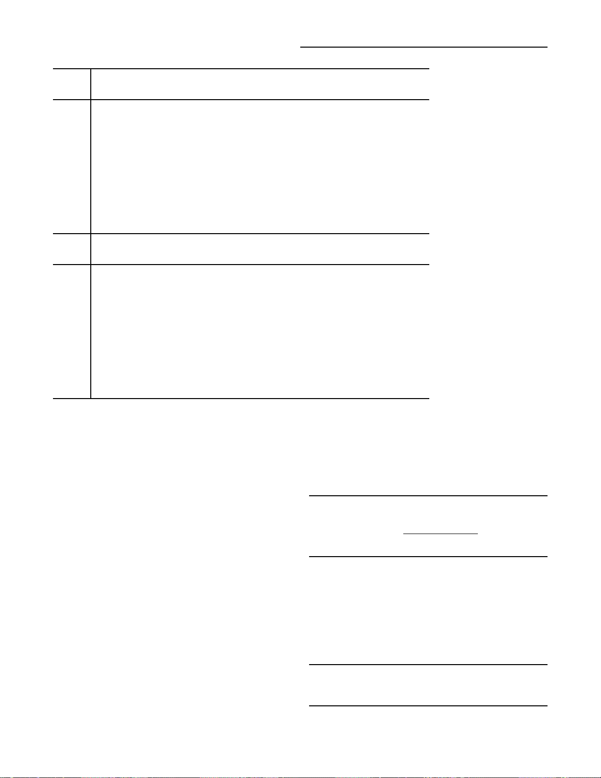
Installation (Continued)
F
F
F
G
G
F
F
F
G
G
Table 3-3
Typical Unit & Curb Weights
Typical Unit Operating Weight (1) Roof Curb
Unit SE,SL,
Size SAH
C20
C25
C30
C40
C50
C55
C60
C70
C75
C90
D11
D12
D13
Unit SE,SL, Max . W eight (3)
Size SAH
C20
C25
C30
C40
C50
C55
C60
C70
C75
C90
D11
D12
D13
Note:
heating/cooling function indicated with an economizer and exhaust fan installed.
2. The weights shown represents the typical unit operating weights for the
heating/cooling function indicated with an economizer, exhaust fan with supply &
exhaust VFD installed.
3. Roof curb weights include the curb and pedestal.
4360 4690 4970 4580 490 510
4520 4860 5130 4750 490 510
5220 5590 5840 5460 490 510
6890 7400 7880 7240 515 550
7890 8450 8900 8290 515 550
8140 8690 9170 8540 515 550
9320 9650 10120 9480 610 640
9860 10160 10640 10040 610 640
9860 10160 10640 10040 610 640
Typical Unit Operating Weight (2) Roof Curb
4650 5000 5270 4860 490 510
4830 5180 5440 5060 490 510
5570 5930 6200 5800 490 510
7290 7820 8280 7650 515 550
8350 8900 9380 8740 515 550
8600 9160 9640 9010 515 550
9840 10150 10620 10010 610 640
10370 10690 11160 10560 610 640
10370 10690 11160 10560 610 640
1. The weights shown in this table represents the typical unit operating weights for the
SSH
SSH
SFH
SFH
SXHFSEHG SFH
14730 15400 14580 770
15310 15940 15160 770
15730 16370 15560 770
16080 16710 15930 770
SXHFSEHG SFH
15460 16050 15240 770
15950 16590 15810 770
16380 17010 16220 770
16730 17380 16580 770
SXH
SXH
Max. Weight (3)
SAHFS*HF/G
SAHFS*HF/G
Roof Curb and Ductwork
The roof curbs for 20 through 130 Ton units consists of two
main components; a pedestal to support the unit’s condenser section and a "full perimeter" enclosure to support
the unit’s air handler section.
Before installing any roof curb, verify;
1. That it is the correct curb for the unit,
2. That it includes the necessary gaskets and
hardware,
3. That the purposed installation location provides
the required clearance for proper operation.
4. Insure that the curb is level and square. The top
surface of the curb must be true to assure an
adequate curb-to-unit seal.
Step-by-step curb assembly and installation instructions
ship with each Trane accessory roof curb kit. Follow the instructions carefully to assure proper fit-up when the unit is
set into place.
22
Note: To assure proper condensate flow during
operation, the unit (and curb) must be as level as
possible. The maximum slope allowable for rooftop
unit applications,
excluding SSH_'s, is 4" end-toend and 2" side-to-side. Units with steam coils
(SSH_'s) must be set level!
If the unit is elevated, a field constructed catwalk around the
unit is strongly recommended to provide easy access for
unit maintenance and service.
Recommendations for installing the Supply Air and Return
Air ductwork joining the roof curb are included in the curb
instruction booklet. Curb ductwork must be fabricated and
installed by the installing contractor before the unit is set
into place.
Note: For sound consideration, cut only the holes
in the roof deck for the ductwork penetrations. Do
not cut out the entire roof deck within the curb
perimeter.
Page 24
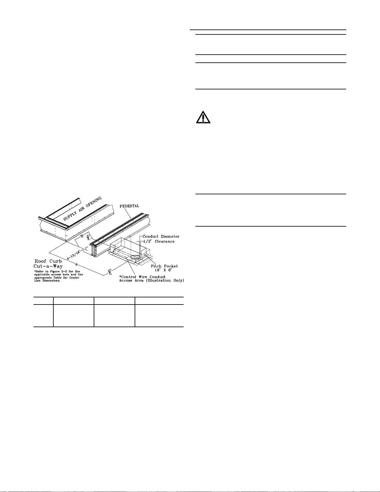
Trane's Engineering Bulletin RT-EB-80 provides additional
information concerning duct design and sound reduction.
Pitch Pocket Location
Installation (Continued)
Note: If a “built-up” curb is provided by others,
keep in mind that these commercial rooftop units
do not have base pans in the condenser section.
The location of the main supply power entry for S_HF 20
through 75 Ton rooftop units is located at the bottom righthand corner of the control panel. Figures 3-2A, B & C illustrate the location for the electrical entrance through the
base in order to enter the control panel. If the power supply
conduit penetrates the building’s roof beneath this opening,
it is recommended that a pitch pocket be installed before
the unit is placed onto the roof curb. The center line dimensions shown in the illustration below indicates the center
line of the electrical access hole in the unit base when it is
positioned on the curb, ±3/8 inch. The actual diameter of
the hole in the roof should be at least 1/2 inch larger than
the diameter of the conduit penetrating the roof. This will allow for the clearance variable between the roof curb rail and
the unit base rail illustrated in Figure 3-5.
The pitch pocket dimensions listed are recommended to enhance the application of roofing pitch after the unit is set
into place. The pitch pocket may need to be shifted as illustrated to prevent interference with the curb pedestal.
Note: If this is a REPLACEMENT UNIT keep in mind
that the CURRENT DESIGN commerical rooftop
unitsdo not have base pans in the condenser
section.
Unit Rigging & Placement
WARNING
Heavy Objects!
Do not use cables (chains or slings) except as shown.
Each of the cables (chains or slings) used to lift the unit
must be capable of supporting the entire weight of the
unit. Lifting cables (chains or slings) may not be of the
same length. Adjust as necessary for even unit lift.
Other lifting arrangements may cause equipment or
property-only damage. Failure to properly lift unit may
result in death or serious injury. See details below.
Note: Use spreader bars as shown in the diagram.
Refer to the Installation manual or nameplate for
the unit weight.Refer to the Installation Instructions
located inside the side control panel for further
rigging information.
1. A Center-of-Gravity illustration and the dimensional data
is shown in Figure 3-3.
Unit Tonnage “A” Dimension "B" Dimension
S*HF 20, 25 & 30 4' 5-9/16" 5-9/16"
S*HF 50 & 55 9' 5-11/16" 5-1/2"
S*HF 40, 60, 70 & 75 6' 9-5/8" 7-3/16"
* = A l l uni t func t i ons (SAHF, S EHF, SFHF, SSHF , SLHF and SXHF)
If a Trane Curb Accessory Kit is not used:
a. The ductwork can be attached directly to the
factory-provided flanges around the unit’s supply and
return air openings. Be sure to use flexible duct
connections at the unit.
b. For “built-up” curbs supplied by others, gaskets must
be installed around the curb perimeter flange and the
supply and return air opening flanges.
2. Attach adequate strength lifting slings to all four lifting
lugs on 20 through 75 Ton units and to all six lifting lugs
on 90 through 130 Ton units. The minimum distance between the lifting hook and the top of the unit should be 7
feet for 20 through 75 Ton units and 12 feet for 90
through 130 Ton units. Figure 3-4 illustrates the installation of spreader bars to protect the unit and to facilitate a
uniform lift. Table 3-3 list the typical unit operating
weights.
3. Test-lift the unit to ensure it is properly r igged and balanced, make any necessary rigging adjustments.
4. Lift the unit and position it over the curb and pedestal.
(These units have a continuous base rail around the air
handler section which matches the curb.
5. Align the base rail of the unit’s air handler section with
the curb rail while lowering the unit onto the curb. Make
sure that the gasket on the curb is not damaged while
positioning the unit. (The pedestal simply supports the
unit’s condenser section)
A cross section of the juncture between the unit and the
roof curb is shown in Figure 3-5.
23
Page 25
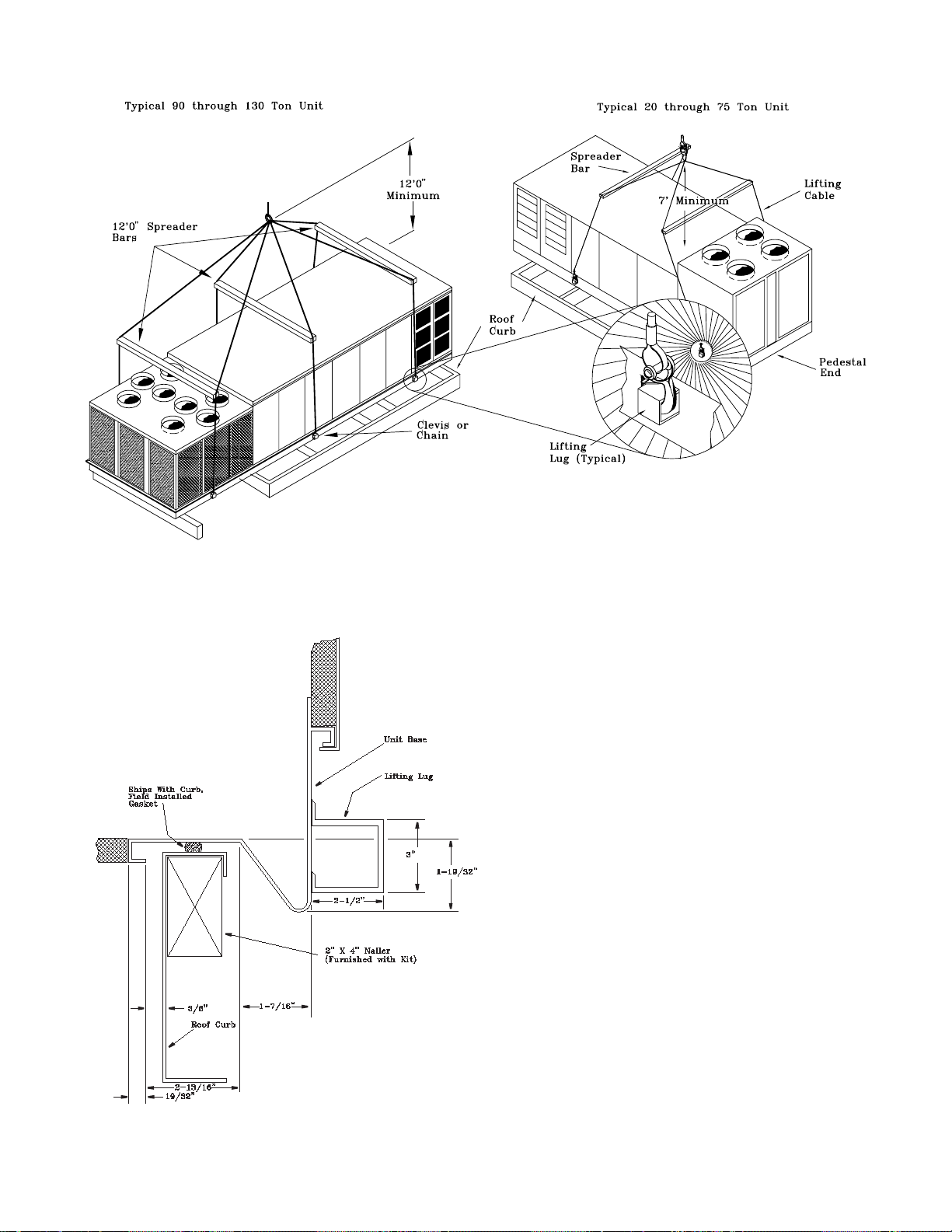
Figure 3-4
Typical Unit Rigging
Figure 3-5
Unit Base & Roof Curb Section
24
Page 26

Installation (Continued)
General Unit Requirements
The checklist listed below is a summary of the steps required to successfully install a Commercial rooftop unit.
This checklist is intended to acquaint the installing personnel with what is required in the installation process. It does
not replace the detailed instructions called out in the applicable sections of this manual.
[ ] Check the unit for shipping damage and material short-
age; file a freight claim and notify Trane office.
[ ] Verify that the installation location of the unit will provide
the required clearance for proper operation.
[ ] Assemble and install the roof curb. Refer to the current
edition of SAHF-IN-5 for 20 through 75 Ton units or
SXHG-IN-2 for 90 through 130 Ton units.
[ ] Fabricate and install ductwork; secure ductwork to curb.
[ ] Install pitch pocket for power supply through building
roof. (If applicable)
[ ] Rigging the unit.
[ ] Set the unit onto the curb; check for levelness.
[ ] Ensure unit-to-curb seal is tight and without buckles or
cracks.
[ ] Install and connect condensate drain lines to each
evaporator drain connection.
[ ] Remove the shipping hardware from each compressor
assembly.
[ ] Remove the shipping hold-down bolts and shipping chan-
nels from the supply and exhaust fans ordered with rub-
ber or spring isolators.
[ ] Check all optional supply and exhaust fan spring isola-
tors for proper adjustment.
[ ] Verify that all plastic coverings are removed from the
compressors.
Field Installed Control Wiring
[ ] Complete the field wiring connections for the constant
volume controls as applicable. Refer to "Field Installed
Control Wiring" for guidelines.
[ ] Complete the field wiring connections for the variable air
volume controls as applicable. Refer to "Field Installed
Control Wiring" for guidelines.
Note: All field-installed wiring must comply with
NEC and applicable local codes.
Requirements for Electric Heat Units
All SEHF Units (380 minimum voltage) & SEHG units.
[ ] Verify that the power supply complies with the electric
heater specifications on the unit and heater nameplate.
[ ] Inspect the heater junction box and control panel; tighten
any loose connections.
[ ] Check electric heat circuits for continuity.
SEHF Units w/200V or 230V Electric Heat:
(Requires Separate Power Supply to Heater)
[ ] Connect properly sized and protected power supply wir-
ing for the electric heat from a dedicated, field- supplied/
installed disconnect to terminal block 4TB2, or to an optional unit mounted disconnect switch 4S15.
Requirements for Gas Heat
[ ] Gas supply line properly sized and connected to the unit
gas train.
[ ] All gas piping joints properly sealed.
[ ] Drip leg Installed in the gas piping near the unit.
[ ] Gas piping leak checked with a soap solution. If piping
connections to the unit are complete, do not pressurize
piping in excess of 0.50 psig or 14 inches w.c. to prevent
component failure.
[ ] Ver ify all discharge and liquid line service valves (one per
circuit) are back seated.
Main Electrical Power Requirements
[ ] Ver ify that the power supply complies with the unit name-
plate specifications.
[ ] Inspect all control panel components; tighten any loose
connections.
[ ] Connect properly sized and protected power supply wir-
ing to a field-supplied/installed disconnect and unit
[ ] Properly ground the unit.
Note: All field-installed wiring must comply with
NEC and applicable local codes.
[ ] Main supply gas pressure adequate.
[ ] Flue Tubes clear of any obstructions.
[ ] Factory-supplied flue assembly installed on the unit.
[ ] Connect the 3/4" CPVC furnace drain stubout to a proper
condensate drain.
Requirements for Hot Water Heat (SLH_)
[ ] Route properly sized water piping through the base of the
unit into the heating section.
[ ] Install the factory-supplied, 3-way modulating valve.
[ ] Complete the valve actuator wiring.
25
Page 27
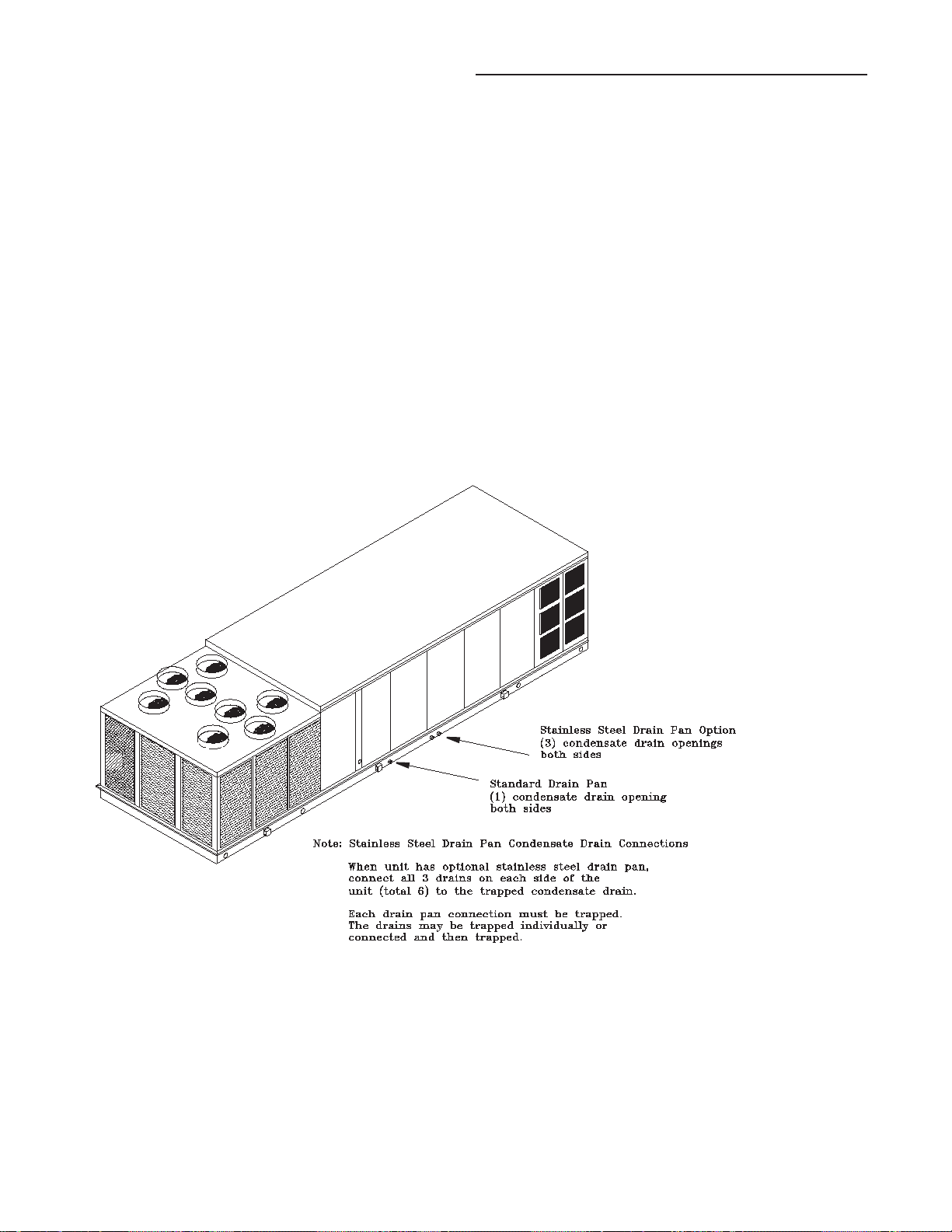
Installation (Continued)
Requirements for Steam Heat (SSH_)
[ ] Install an automatic air vent at the top of the return water
coil header.
[ ] Route properly sized steam piping through the base of
the unit into the heating section.
[ ] Install the factory-supplied, 2-way modulating valve
[ ] Complete the valve actuator wiring.
[ ] Install 1/2", 15-degree swing-check vacuum breaker(s) at
the top of each coil section. Vent breaker(s) to theatmo-
sphere or merge with return main at discharge side of
steam trap.
[ ] Position the steam trap discharge at least 12" below the
outlet connection on the coil.
Figure 3-6A
Condensate Drain Locations
[ ] Use float and thermostatic traps in the system, as re-
quired by the application.
O/A Pressure Sensor and Tubing Installation
(All units with Statitrac)
[ ] O/A pressure sensor mounted to the roof bracket.
[ ] Factory supplied pneumatic tubing installed between the
O/A pressure sensor and the connector on the vertical
support.
[ ] Field supplied pneumatic tubing connected to the proper
fitting on the space pressure transducer located in the
filter section, and the other end routed to a suitable sensing location within the controlled space.
26
Page 28
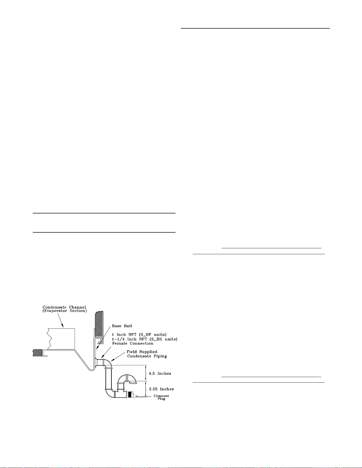
Installation (Continued)
Condensate Drain Connections
Each S_HF unit is provided with two or six 1" evaporator
condensate drain connections (one on each side of the
unit). Each S_HG unit is provided with two or six 1-1/4"
evaporator drain connections (one on each side of the unit.)
Due to the size of these units, all condensate drain connection must be connected to the evaporator drain connections. Refer to the appropriate illustration in Figure 3-2 for
the location of these drain connections.
A condensate trap must be installed due to the drain connection being on the "negative pressure" side of the fan. Install the P-Traps at the unit using the guidelines in Figure 3-
6.
Pitch the drain lines at least 1/2 inch for every 10 feet of
horizontal run to assure proper condensate flow. Do not allow the horizontal run to sag causing a possible double-trap
condition which could result in condensate backup due to
"air lock".
Units with Gas Furnace
Units equipped with a gas furnace have a 3/4" CPVC drain
connection stubbed out through the vertical support in the
gas heat section. It is extremely important that the condensate be piped to a proper drain. Refer to the appropriate illustration in Figure 3-2 for the location of the drain connection.
Note: Units equipped with an optional modulating
gas furnace will likely operate in a condensing
mode part of the time.
An additional 1-1/4" non-connectable water drain is located
in the base rail within the heating section.
Ensure that all condensate drain line installations comply
with applicable building and waste disposal codes.
Figure 3-6
Condensate T rap Installation
Shipping Fasteners
the unit's base rail. To locate and remove the shipping hardware, refer to Figure 3-7 and the following procedure.
1. Remove the four anchor bolts (2 front and 2 rear), used
to secure the shipping brace to the unit's base rail (two
assemblies on 40 through 60 Ton units).
2. Remove the three self-tapping screws that secure each
shipping brace to the compressor mounting rails.
3. Remove and discard the two 30-1/2" long shipping
braces for each assembly.
4. Do not remove the shipping bracket located on top of the
compressors.
5. Ensure that the compressor rail assembly is free to move
on the rubber isolators.
Removing Compressor Assembly Shipping Hardware
(70 & 105 Ton)
Each manifolded compressor assembly is rigidly bolted to a
mounting rail assembly. The rail assembly sets on six (6)
rubber isolators. The assembly is held in place by four (4)
shipping "Tiedown" bolts. To remove the shipping hardware,
follow the procedures below:
1. At each "Tiedown" location (2 front and 2 rear), remove
and discard the tiedown bolt and the slotted shipping
spacer located between the compressor rails and the
unit base rail illustrated in Figure 3-7B, "Tiedown Bolt"
detail.
2. Remove the bolt in each rubber isolator and the slotted
shipping spacer located between the compressor rails
and the unit base rail illustrated in Figure 3-7B, "Isolator
Bolt" detail.
screwing them into the base rail two to three turns only.
3. Ensure that the compressor rail assembly is free to move
on the rubber isolators.
Removing Compressor Assembly Shipping Hardware
(115 and 130 Ton)
Each manifolded compressor assembly is rigidly bolted to a
mounting rail assembly. The rail assembly sets on eight (8)
rubber isolators. The assembly is held in place by six (6)
"Tiedown Bolts". To remove the shipping hardware, follow
the procedure below:
Reinstall the bolts at the same location by
Removing Compressor Assembly Shipping Hardware
(20 through 60 Ton)
Each manifolded compressor assembly is rigidly bolted to a
mounting rail assembly. The rail assembly sets on four (4)
rubber isolators. The assembly is held in place by two shipping braces that secure each compressor rail assembly to
1. At each "Tiedown" location (6), remove and discard the
tiedown bolt and the slotted shipping spacer located between the compressor rails and the unit base rail illustrated in Figure 3-7C, "Tiedown Bolt" detail.
2. Remove the bolt in each rubber isolator and the slotted
shipping spacer located between the compressor rails
and the unit base rail illustrated in Figure 3-7C, "Isolator
Bolt" detail.
screwing them into the base rail two to three turns only.
3. Ensure that the compressor rail assembly is free to move
on the rubber isolators.
27
Reinstall the bolts at the same location by
Page 29
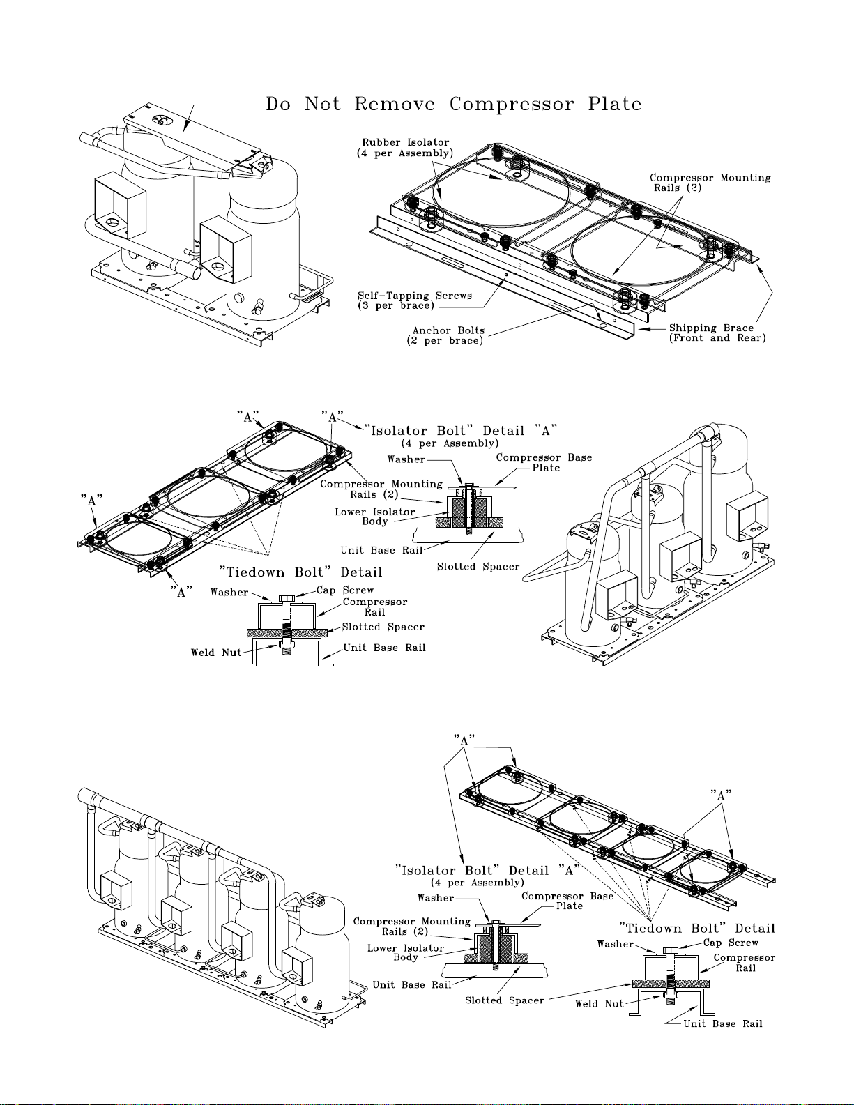
Figure 3-7A
Removing Scroll Compressor Shipping Hardware for 20 through 60 Ton Units
Figure 3-7B
Removing Scroll Compressor Shipping Hardware for 70 through 105 Ton Units
Figure 3-7C
Removing Scroll Compressor Shipping Hardward for 115 and 130 Ton Units
28
Page 30

Installation (Continued)
Removing Supply and Exhaust Fan Shipping Channels
(Motors >5Hp)
Each supply fan assembly and exhaust fan assembly for
S_HF units shipped with a motor larger than 5 HP is
equipped with rubber isolators, (as standard), or optional
spring isolators. Each supply fan assembly and exhaust fan
assembly for S_HG units is equipped with spring isolators.
Shipping channels are installed beneath each fan assembly
and must be removed. To locate and remove these channels, refer to Figure 3-8 and use the following procedures.
Rubber Isolators:
1. Remove and discard the shipping bolts from the fan assembly rails.
2. Elevate the fan-and-motor assembly and slide the shipping
channels out from between the fan assembly rails and the
unit's base rail.
3. Lower the fan-and-motor assembly onto the isolators.
Make sure that the pins at the top of the isolators are engaged in the corresponding holes on the fan assembly.
4. Verify that the fan assembly is being supported by the isolators.
Spring Isolators:
Spring isolators for the supply and/or exhaust fan are
shipped with the isolator adjusting bolt backed out. Field
adjustment is required for proper operation. Figure 3-8
shows isolator locations. To adjust the spring isolators
use the following procedure.
1. Remove and discard the shipping tie down bolts but
leave the shipping channels in place during the adjustment procedure. See Figure 3-8.
2. Tighten the leveling bolt on each isolator until the fan
assembly is approximately 1/4" above each shipping
channel.
3. Secure the lock nut on each isolator.
4. Remove the shipping channels and discard.
29
Page 31

Figure 3-8
Removing Fan Assembly Shipping Hardware (20 through 75 Ton)
Note: Fan assemblies not equipped with rubber or spring isolators have mounting bolts at the same locations
and must not be removed.
(90 through 130 Ton)
30
Page 32
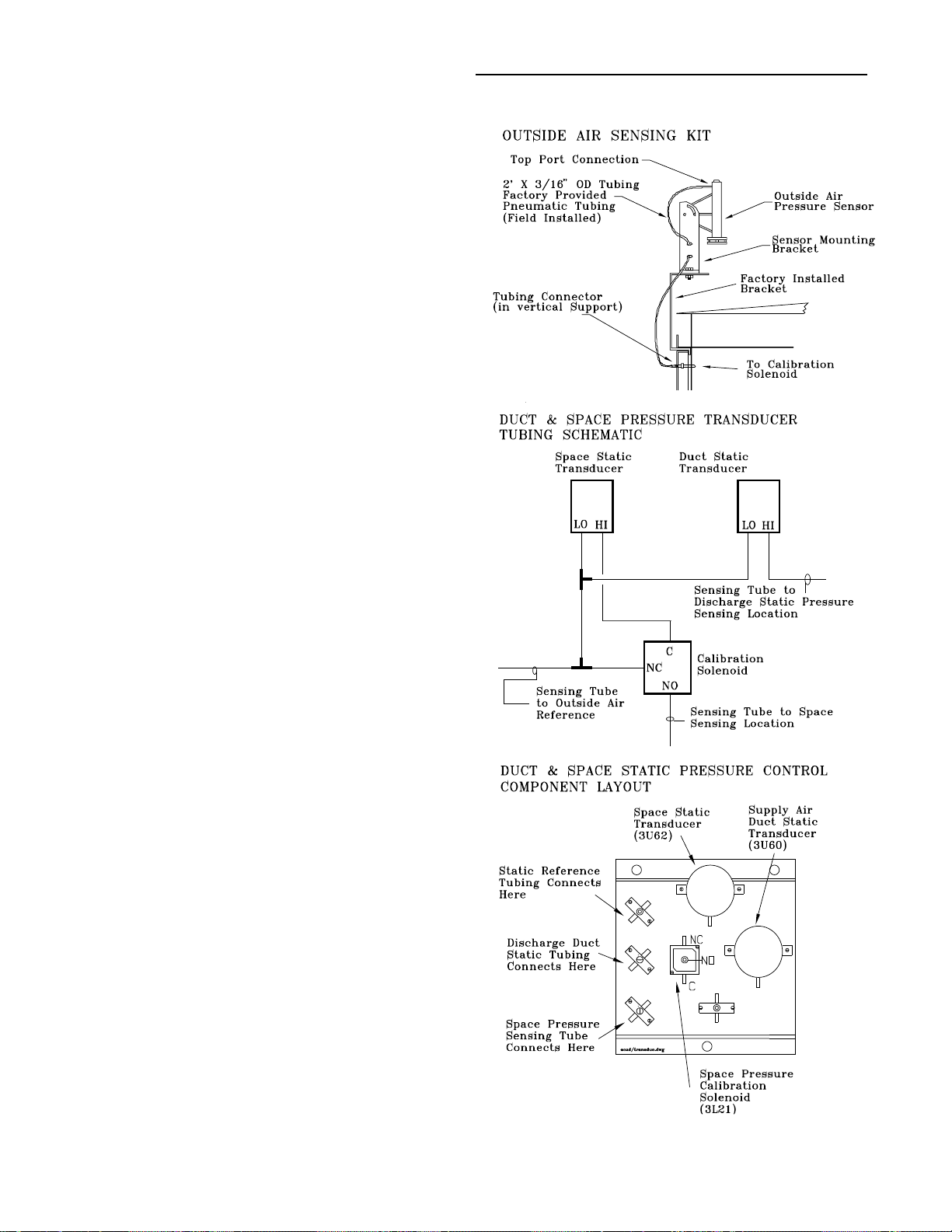
Installation (Continued)
O/A Sensor & Tubing Installation
An Outside Air Pressure Sensor is shipped with all units designed to operate on variable air volume applications or
constant volume units with 100% modulating exhaust w/
Stratitrac.
On VAV systems, a duct pressure transducer (3U60) and
the outside air sensor is used to control the discharge duct
static pressure to within a customer-specified parameter.
On CV & VAV units equipped with 100% modulating exhaust w/Stratitrac, a space pressure transducer (3U62) and
the outside air sensor is used to control the exhaust fan and
dampers to relieve static pressure, to within a customerspecified parameter, within the controlled space. Refer to
Figure 3-9 and the following steps to install the sensor and
the pneumatic tubing.
1. Remove the O/A pressure sensor kit located inside the
filter section. The kit contains the following items;
O/A static pressure sensor with sensor mounting
bracket
2' of 3/16" O.D. pneumatic tubing
Mounting hardware
2. Using two #10-32 x 1-3/4" screws provided, install the
sensor's mounting bracket to the factory installed bracket
(near the filter section).
Figure 3-9
3. Using the #10-32 x 1/2" screws provided, install the O/A
static pressure sensor vertically to the sensor bracket.
4. Remove the dust cap from the tubing connector located
below the sensor in the vertical support.
5. Attach one end of the 2' x 3/16" O.D. factory provided
pneumatic tubing to the sensor's top port, and the other
end of the tubing to the connector in the vertical support.
Discard any excess tubing.
Units with StatitracTM:
6. Open the filter access door, and locate the DSP control
devices illustrated in Figure 3-9. There are three tube
connectors mounted on the left of the solenoid and
transducers. Connect one end of the field provided 3/16"
O.D. pneumatic tubing for the space pressurization control to the bottom fitting. Route the opposite end of the
tubing to a suitable location inside the building. This location should be the largest open area that will not be affected by sudden static pressure changes.
31
Page 33

Installation (Continued)
Gas Heat Units (SFH_)
All internal gas piping is factory-installed and pressure leaktested before shipment. Once the unit is set into place, the
gas supply line must be field-connected to the elbow located inside the gas heat control compartments.
WARNING
Hazardous Gases and Flammable Vapors!
Exposure to hazardous gases from fuel substances
have been shown to cause cancer, birth defects or
other reproductive harm. Improper installation, adjustment, alteration, service or use of this product could
cause flammable mixtures. To avoid hazardous gases
and flammable vapors follow proper installation and set
up of this product and all warnings as provided in this
manual. Failure to follow all instructions could result in
death or serious injury.
When using dry nitrogen cylinders for pressurizing
units for leak testing, always provide a pressure regulator on the cylinder to prevent excessively high unit
pressures. Never pressurize unit above the maximum
recommended unit test pressure as specified in applicable unit literature. Failure to properly regulate pressure could result in a violent explosion, which could result in death or serious injury or equipment or property-only-damage. (add when appropriate: See maximum recommended unit test pressure below.)
Access holes are provided on the unit as illustrated in Figure 3-2B to accomodate a side or bottom pipe entry on 20
through 75 Ton units and Figure 3-2C for bottom entry on
90 through 130 Ton units. Following the guidelines listed
below will enhance both the installation and operation of the
furnace.
Note: In the absence of local codes, the installation
must conform with the American National Standard
Z223-1a of the National Fuel Gas Code, (latest
edition).
1. To assure sufficient gas pressure at the unit, use Table 34 as a guide to determine the appropriate gas pipe size
for the unit heating capacity listed on the unit's nameplate.
2. If a gas line already exist, verify that it is sized large
enough to handle the additional furnace capacity before
connecting to it.
3. Take all branch piping from any main gas line from the
top at 90 degrees or at 45 degrees to prevent moisture
from being drawn in with the gas.
6. Install a pressure regulator at the unit that is adequate to
maintain 7" w.c. for natural gas while the furnace is operating at full capacity.
Note: Gas pressure in excess of 14" w.c. or 0.5 psig
will damage the gas train.
Failure to use a pressure regulating device will result in incorrect gas pressure. This can cause erratic operation due
to gas pressure fluctuations as well as damage the gas
valve.
Over sizing the regulator will cause irregular pulsating flame
patterns, burner rumble, potential flame outages, and possible gas valve damage.
If a single pressure regulator serves more than one rooftop
unit, it must be sized to ensure that the inlet gas pressure
does not fall below 7" w.c. with all the furnaces operating at
full capacity. The gas pressure must not exceed 14" w.c.
when the furnaces are off.
7. Provide adequate support for all field installed gas piping
to avoid stressing the gas train and controls.
8. Leak test the gas supply line using a soap-and-water solution or equivalent before connecting it to the gas train.
9. Check the supply pressure before connecting it to the
unit to prevent possible gas valve damage and the unsafe operating conditions that will result.
Note: Do not rely on the gas train shutoff valves to
isolate the unit while conducting gas pressure/leak
test. These valves are not designed to withstand
pressures in excess of 14" w.c. or 0.5 psig.
Connecting the Gas Supply Line to the Furnace Gas
Train
Follow the steps below to complete the installation between
the supply gas line and the furnace. Refer to Figure 3-10 for
the appropriate gas train configuration.
1. Connect the supply gas piping using a "ground-joint" type
union to the furnace gas train and check for leaks.
2. Adjust the inlet supply pressure to the recommended 7"
to 14" w.c. parameter for natural gas.
3. Ensure that the piping is adequately supported to avoid
gas train stress.
4. Ensure that all piping connections are adequately coated
with joint sealant and properly tightened. Use a piping
compound that is resistant to liquid petroleum gases.
5. Provide a drip leg near the unit.
32
Page 34

Installation (Continued)
Table 3-4
Sizing Natural Gas Pipe Mains & Branches
Siz ing Natu ral Gas Pip e Main s & Branch es
G as Input (Cubic F eet/Hour)* Notes:
1. If more th an one u nit is served by
G as Supply 1-1/4" 1-1/2" 2" 2-1/2" 3" 4"
Pipe R un (ft) Pip e Pip e Pipe Pipe Pipe Pip e
10
20
30
40
50
60
70
80
90
100
125
150
175
200
* Ta ble is based on a specific gr a vity of 0.60 . Use Table 3- 1 for Gas BT U/Cu.F t. X Multiplier (Ta ble 3- 1)
specific gravity of the local gas supply. Cu.Ft/Hour = 500
Specific Gravity Multipliers
Speci f ic Gas Heat in g Capacit y Altitude Correction Facto rs
G ravity Multiplier
0.50 1.10
0.55 1.04 T o 2000 To 2500 To 3500 To 4500 To 5500 To 6500 To 7500
0.60 1.00
0.65 0.96 Multiplier 1.00 .92 .88 .84 .80 .76 .72
1050 1600 3050 4800 8500 17500 and t he total length when deter mining
730 1100 2100 3300 5900 12000 the appropr iate gas pipe size.
590 890 1650 2700 4700 9700 2. O btain the S pec ific Gravity and
500 760 1450 2300 4100 8300 BTU/Cu.F t. f r o m the ga s company.
440 670 1270 2000 3600 7400 3. T he following e xample demonstr ates
400 610 1150 1850 3250 6800 the con siderat io ns necessary whe n
370 560 1050 1700 3000 6200 determining t he a c tual pipe size.
350 530 990 1600 2800 5800
320 490 930 1500 2600 5400 Example: A 40' pipe run is needed to
305 460 870 1400 2500 5100 connec t a unit wit h a 50 0 MBH fur n ac e to a
275 410 780 1250 2200 4500 natural gas supply having a rating of 1,000
250 380 710 1130 2000 4100 BT U/Cu.Ft. an d a specific g r avity of 0. 60
225 350 650 1050 1850 3800
210 320 610 980 1700 3500 Cu.Ft/Hour = F ur nac e MBH Input
Sea Level 2001 2501 3501 4501 5501 6501
Capacity
Not e: Corr e c tion factors are per AGA Std. 221.30 - 1 964, Part VI, 6.12.
Loc al c o des may supersede.
the same main gas supply, c on sider
the tot a l gas input (cubic feet /hr.)
Table 3 indic ates that a 1-1/ 4" pipe is required.
Altitu d e (Ft.)
Figure 3-10
Unit Gas Trains (Natural Gas)
235 and 350 MBH
500 and 850 MBH
33
Page 35

Installation (Continued)
Figure 3-10 (Continued)
Unit Gas Trains (Natural Gas)
1000 MBH
4. Insert the tube on the flue assembly into the hole located
in the vertical support for the heat section.
5. Butt both flue tube sections together and center the pipe
clamp over joint.
6. Using the pre-punch holes in the flue assembly, extension, and the vertical support, install the appropriate
number of mounting brackets. Refer to Figure 3-11 for
details.
Figure 3-11
Flue Assembly
Modulating (500 MBH - 1000 MBH)
Flue Assembly Installation
1. Locate the flue assembly and the extension (refer to Figure 3-11 for extension usage) in the shipwith section of
the unit.
Hot Water Heat Units (SLH_)
Hot water heating coils are factory installed inside the
heater section of the unit. Once the unit is set into place,
the hot water piping and the factory provided three way
modulating valve must be installed. The valve can be installed inside the heat section or near the unit. If the valve
is installed in a remote location, use field supplied wiring to
extend the control wires from the heater section to the
valve. Two access holes are provided in the unit base as illustrated in Figure 3-2.
Following the guidelines listed below will enchance both the
installation and operation of the "wet heat" system.
Figure 3-12 illustrates the recommended piping configuration for the hot water coil. Table 3-5 list the coil connection
sizes.
Note: The valve actuators are not waterproof.
Failure to protect the valve from moisture may
result in the loss of heating control.
1. Support all field-installed piping independently from the
heating coil.
2. Install the flue extension onto the flue assembly as
shown in Figure 3-11.
3. Slide the pipe clamp onto the heater flue tube located inside the heater compartment.
2. Use swing joints or flexible connectors adjacent to the
heating coil. (These devices will absorb the strains of expansion and contraction).
3. All return lines and fittings must be equal to the diameter
of the "outlet" connection on the hot water coil.
34
Page 36

Installation (Continued)
(
)
y
(
)
t
t
t
t
4. Install a "Gate" type valve in the supply branch line as
close as possible to the hot water main and upstream of
any other device or takeoff.
5. Install a "Gate" type valve in the return branch line as
close as possible to the return main and down stream of
any other device.
6. Install a strainer in the hot water supply branch as shown
in Figure 3-12.
7. Install the 3-way valve in an upright position, piped for
valve seating against the flow. Ensure that the valve's location lends itself to serviceability.
8. The Type "W" hot water coil used in SLHF units is selfventing only when the tube water velocity exceeds 1.5
feet per second (fps). If the tube velocity is less than 1.5
feet per second, either:
a. install an automatic air vent at the top of the return
header, using the tapped pipe connection;
or,
b. vent the coil from the top of the return header down
to the return piping. At the vent connection, size the
return piping to provide sufficient water velocity.
9. Install a "Globe" type valve in the Bypass line as shown
in Figure 3-12.
Table 3-5
Connection Sizes for Hot Water & Steam Coil
(See Note 1)
Heat Coil Connections
Section
di ameter i n i n ches
Uni t M od el Capacit
and Size
Not e 2
Supply Return
SLH*-20 High or 2-1/2" 2-1/2"
to 130 Low Hea
SSHF-20 High or
to 30 Low Hea
3" 1-1/4"
SSHF-40 High Heat 3" 1-1/2"
to 75
(Not e 3) Low Hea
1-1/2" 1"
SSHG-90 Low Hea
to 130 (Not e 3)
Notes:
1. Type W coils—with center offset headers—are used in
SLH_ units; Type NS coils are used in SSH_ units.
2. See Digit 9 of the unit model number to determine the
heating capacity.
3. SSH_ - 40 to 130 Ton units have multiple headers.
Steam Heat Units (SSH_)
Steam heating coils are factory installed inside the heater
section of the unit. The coils are pitched, within the units, to
provide the proper condensate flow from the coil. To maintain the designed degree of pitch for the coil, the unit must
be level.
Once the unit is set into place, the steam piping and the
factory provided two way modulating valve must be installed. The valve can be installed inside the heater section
or near the unit. If the valve is installed in a remote location,
use field supplied wiring to extend the control wires from
the heater section to the valve. Two access holes are provided in the unit base as illustrated in Figure 3-2.
Following the guidelines listed below will enhance both the
installation and operation of the "wet heat" system.
Figure 3-13 illustrates the recommended piping configurations for the steam coil. Table 3-5 list the coil connection
sizes.
Note: The valve actuators are not waterproof.
Failure to protect the valve from moisture may
result in the loss of heating control.
1. Support all field-installed piping independently from the
heating coil.
2. Use swing joints or flexible connectors adjacent to the
heating coil. (These devices will absorb the strains of expansion and contraction.)
3. Install the 2-way valve in an upright position. Ensure that
the valve's location lends itself to serviceability.
4. Pitch the supply and return steam piping downward 1"
per 10' of run in the direction of flow.
5. All return lines and fittings must be equal to the diameter
of the "outlet" connection on the steam coil(s). If the
steam trap connection is smaller that the coil "outlet" diameter, reduce the pipe size between the strainer and
the steam trap connections only.
6. Install a 1/2" 15 degree swing-check vacuum breaker at
the top of the return coil header using the tapped pipe
connection. Position the vacuum breaker as close to the
coil as possible.
Note: Vacuum breakers should have extended lines
from the vent ports to the atmosphere or connect
each vent line to the return pipe on the discharge
side of the steam traps.
7. Install a "Gate" type valve in the supply branch line as
close as possible to the steam main and upstream of any
other device.
8. Install a "Gate" type valve in the return branch line as
close as possible to the condensate return main and
downstream of any other device.
9. Install a strainer as close as possible to the inlet of the
control valve and steam trap(s).
10. Steam trap selection should be based on the maximum
possible condensate flow and the recommended load
factors.
11. Install a Float-and-Thermostatic (FT) type trap to maintain proper flow. They provide gravity drains and continuous discharge operation. FT type traps are required if the
system includes either;
a. an atmospheric pressure/gravity condensate return;
or,
b. a potentially low pressure steam supply.
35
Page 37

Installation (Continued)
12. Position the outlet or discharge port of the steam trap at
least 12" below the outlet connection on the coil(s). This
will provide adequate hydrostatic head pressure to overcome the trap losses and assure complete condensate
removal.
40 through 130 Ton units;
Utilizes two steam coils stacked together. These two coils
must be piped in a parallel arrangement. The steps listed
below should be used in addition to the previous steps. Figure 3-13 illustrates the recommended piping configuration
for the steam coils.
Figure 3-12
Hot Water Piping (20 through 75 Ton)
13. Install a strainer in each return line before the steam
trap.
14. Trap each steam coil separately as described in steps
10 and 11 to prevent condensate backup in one or both
coils.
15. In order to prevent condensate backup in the piping
header suppling both coil sections, a drain must be installed utilizing a strainer and a steam trap as illustrated
in Figure 3-13.
Hot Water Piping (90 through 130 Ton)
36
Page 38

Figure 3-13
Steam Coil Piping (20 through 30 Ton Units)
Steam Coil Piping (40 through 130 Ton Units)
37
Page 39

Installation (Continued)
Disconnect Switch External Handle
(Factory Mounted Option)
Units ordered with the factory mounted disconnect switch
comes equipped with an externally mounted handle. This
allows the operator to disconnect power from the unit without having to open the control panel door. The handle locations and its three positions are shown below;
"ON" - Indicates that the disconnect switch is closed,
allowing the main power supply to be applied at the
unit.
"OFF" - Indicates that the disconnect switch is open,
interrupting the main power supply to the unit
controls.
"OPEN COVER/RESET" - Turning the handle to this
position releases the handle from the disconnect
switch, allowing the control panel door to be
opened.
WARNING
Hazardous Voltage!
Disconnect all electric power, including remote disconnects before servicing. Follow proper lockout/tagout
procedures to ensure the power can not be inadvertently energized. Failure to disconnect power before servicing could result in death or serious injury.
Once the door has been opened, it can be closed with the
handle in any one of the three positions outlined above,
provided it matches the disconnect switch position.
The handle can be locked in the "OFF" position. While
holding the handle in the "OFF" position, push the spring
loaded thumb key, attached to the handle, into the base
slot. Place the lock shackle between the handle and the
thumb key. This will prevent it from springing out of position.
An overall layout of the field required power wiring is illustrated in Figure 3-14. T insure that the unit's supply power
wiring is properly sized and installed, follow the
guildelines outlined below.
handling live electrical components perform these
tasks. Failure to follow all electrical safety precautions
when exposed to live electrical components could result
in death or serious injury.
Verify that the power supply available is compatible with
the unit's nameplate rating for all components. The available power supply must be within 10% of the rated voltage
stamped on the nameplate. Use only copper conductors to
connect the 3-phase power supply to the unit.
CAUTION
Use Copper Conductors Only!
Unit terminals are not designed to accept other types of
conductors. Failure to use copper conductors may result in equipment damage.
Electric Heat Units (SEH_)
SEHF (20 through 75 Ton) electric heat units operating on
200/230 volts require two power supplies as illustrated in
Figure 3-14. Unless the unit was ordered with the optional
factory mounted non-fused disconnect switches, two fieldsupplied disconnect switches must be installed. The power
wires for the electric heat is routed into the electric heat
control panel using the thru-the-base access provided in the
heating section. Refer to the appropriate illustration in Figure 3-2, (Unit Base layout and Electrical Entrance diagram),
for dimensional data.
20 through 75 Ton units operating on 460/575 volts and all
90 through 130 Ton units require one power entry as illustrated in Figure 3-14.
Use the information provided in Table 3-7 and the "Power
Wire Sizing & Protection Device Equations", to determine
the appropriate wire size and Maximum Over current Protection for the heaters/unit.
Note: Each power supply must be protected from
short circuit and ground fault conditions. To
comply with NEC, protection devices must be sized
according to the "Maximum Over current
Protection" (MOP) or "Recommended Dual
Element" (RDE) fuse size data on the unit
nameplate.
Provide grounding for the supply power circuit in the electric heat control box.
Note: All field installed wiring must conform to NEC guidelines as well as State and Local codes.
WARNING
Live Electrical Components!
During installation, testing, servicing and troubleshooting of this product, it may be necessary to work with live
electrical components. Have a qualified licensed electrician or other individual who has been properly trained in
Main Unit Power Wiring
Table 3-6 list the field connection wire ranges for both the
main power terminal block 1TB1 and the optional main
power disconnect switch 1S14. Table 3-7 list the component electrical data for 20 through 130 Ton units. The electrical service must be protected from over current and short
circuit conditions in accordance with NEC requirements.
Protection devices must be sized according to the electrical data on the nameplate. Refer to the "Power Wire Sizing
& Protection Device Equations", for determining;
a. the appropriate electrical service wire size based on
"Minimum Circuit Ampacity" (MCA),
b. the "Maximum Over current Protection" (MOP)
device,
c. the "Recommended Dual Element fuse size" (RDE).
38
Page 40

2. If the unit is not equipped with an optional factory installed non-fused disconnect switch, a field supplied disconnect switch must be installed at or near the unit in accordance with the National Electrical Code (NEC latest
edition). Refer to the "Power Wire Sizing & Protection Device Equations" (DSS calculation), for determining the
correct size.
Figure 3-14
Typical Field Power Wiring (20 thru 75 Ton)
Installation (Continued)
3. Location for the electrical service entrance is illustrated in
Figure 3-2. Complete the unit's power wiring connections
onto either the main terminal block 1TB1, or the factory
mounted non-fused disconnect switch 1S14, inside the
unit control panel. Refer to the customer connection diagram that shipped with the unit for specific termination
points.
4. Provide proper grounding for the unit in accordance with
local and national codes.
39
Page 41
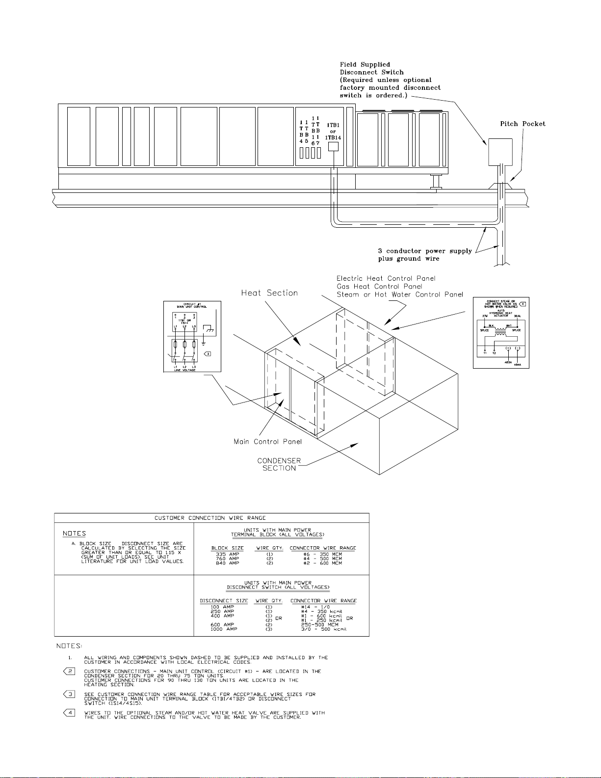
Figure 3-14 (Continued)
Typical Field Power Wiring (90 thru 130 Ton)
Table 3-6
Customer Connection Wire Range
40
Page 42

Table 3-7
p
)
(
)
(
)
(
)
(
)
)
(1)
)
)
pply
)
)
)
)
p
Electrical Service Sizing Data (20 through 130 Ton)
Unit 200/60/3, Nominal 230/60/3, Nominal 460/60/3, Nominal 575/60/3, Nominal
onent(s
Com
Compressor:
20 A & B 41.9 269 41.9 251 18.2 117 14.6 94
25 B 62.8 409 62.8 376 27.3 178 21.8 143
A 41.9 269 41.9 251 18.2 117 14.6 94
30 A & B 62.8 409 62.8 376 27.3 178 21.8 143
40 1,2A, 1,2B 41.9 269 41.9 251 18.2 117 14.6 94
50 1B & 2B 62.8 409 62.8 376 27.3 178 21.8 143
1A & 2A 41.9 269 41.9 251 18.2 117 14.6 94
55 1,2A, 1,2B 62.8 409 62.8 376 27.3 178 21.8 143
60 1,2A, 1,2B 62.8 409 62.8 376 27.3 178 21.8 143
70 1,2A, 1,2B 41.9 269 41.9 251 18.2 117 14.6 94
1,2C 62.8 409 62.8 376 27.3 178 21.8 143
75 1,2A, 1,2B 41.9 269 41.9 251 18.2 117 14.6 94
1,2C 62.8 409 62.8 376 27.3 178 21.8 143
75 Hi-Cap 1,2A, 1,2B 41.9 269 41.9 251 18.2 117 14.6 94
1,2C 62.8 409 62.8 376 27.3 178 21.8 143
90 1,2A 41.9 269 41.9 251 18.2 117 14.6 94
1,2B & 62.8 409 62.8 376 27.3 178 21.8 143
1,2C
105 1,2A 62.8 409 62.8 376 27.3 178 21.8 143
1,2B
1,2C
115 1,2A & 62.8 409 62.8 376 27.3 178 21.8 143
1,2B
1,2C & 41.9 269 41.9 251 18.2 117 14.6 94
1,2D
130 1,2A,B,C,D 62.8 409 62.8 376 27.3 178 21.8 143
Condenser Fans: Total FLA
20 Ton - 2 fans 8.2 8.2 3.6 2.8
25/30 Ton - 3 fans 12.3 12.3 5.4 4.2
40 Ton - 4 fans 16.4 16.4 7.2 5.6
50 - 75 Ton, 6 fans 24.6 24.6 10.8 8.4
90 Ton, 8 fans 32.8 32.8 14.4 11.2
105 & 115 Ton, 10 41 41 24 14
fans
130 Ton, 12 fans 49.2 49.2 28.8 16.8
Su
Horsepower:
3.0 HP 10.4 9 4.5 3.8
5.0 HP 16 14.2 7.1 5.8
7.5 HP 24.8 21.6 10.8 8.6
10.0 HP 30.6 26.6 13.3 10.6
15.0 HP (2) 44.9 40 20 15.6
20.0 HP (2) 57.5 51 25.5 20.5
25.0 HP (2) 75 65 32.5 26
30.0 HP (2) 81 74 37 31
40.0 HP (2) 121 105.8 52.9 42.4
Exhaust Fan Motor FLA FLA FLA FLA
Horse
1.5 HP 5.5 4.8 2.4 1.9
3.0 HP 10.4 9 4.5 3.8
5.0 HP 16 14.2 7.1 5.8
7.5 HP 24.8 21.6 10.8 8.6
10.0 HP 30.6 26.6 13.3 10.6
15.0 HP 44.9 40 20 15.6
20.0 HP 57.5 51 25.5 20.5
25-HP 75 65 32.5 26
30-HP 81 74 37 31
40-HP 121 105.8 52.9 42.4
Notes:
1. “Full load amp” values represents the total condenser fan amps.
2. Two (2) motors are used on 90 through 130 Ton units.
Fan Motor FLA (ea.
ower:
180-220V Utiliz.
RLA (ea)LRA (ea)RLA(ea)LRA (ea)RLA (ea)LRA (ea)RLA (ea)LRA (ea
Total FLA (1) Total FLA (1
207-253V Utiliz.
FLA (ea.
414-506V Utiliz.
FLA (ea.
517-633V Utiliz.
Total FLA (1
FLA (ea.
41
Page 43

Table 3-7 (Continued)
Electrical Service Sizing Data (20 through 130 Ton)
Unit 200/60/3, Nominal 230/60/3, Nominal 460/60/3, Nominal 575/60/3, Nominal
Component(s) (180-220V Utiliz.) (207-253V Utiliz.) (414-506V Utiliz.) (51 7-633 V Utiliz.)
Electric Heat FLA (3) FLA (3) FLA (3) FLA (3)
(SEHF Only):
30 Kw 83.3 72.2 36.1 28.9
50 Kw 138.8 120.3 60.1 48.1
70 Kw 194.3 168.4 84.2 67.4
90 Kw 249.8 216.5 108.3 86.6
110 Kw 305.3 264.6 132.3 105.9
130 Kw -n/a- -n/a- 156.4 125.1
150 Kw -n/a- -n/a- 180.4 144.3
170 Kw -n/a- -n/a- 204.5 163.6
190 Kw -n/a- -n/a- 228.5 182.8
Combustion FLA FLA FLA FLA
Blow er Motor
(SFHF Only):
235, 350, 500 MB 2.1 1.8 0.9 0.7
850 & 1,000 MBh 2.8 2.4 1.2 1
Unit Tonnage No. of Compressors Tonnage Type Designation
20 Ton Std and Hi-Capacity Two 9 - Ton Scrolls A & B
25 Ton Std and Hi-Capacity One 14 - Ton Scroll B
One 9 - Ton Scroll A
30 Ton Std and Hi-Capacity Two 14 - Ton Scrolls A & B
40 Ton Std and Hi-Capacity Four 9 - Ton Scrolls 1A, 1B, 2A, 2B
50 Ton Std and Hi-Capacity Two 14 - Ton Scrolls 1B & 2B
Two 9 - Ton Scrol ls 1A & 2A
55 Ton Std and Hi-Capacity Four 14 - Ton Scrolls 1A, 1B, 2A, 2B
60Ton Std and Hi-Capacity Four 14 - Ton Scrolls 1A, 1B, 2A, 2B
70 / 75 Ton Std Four 9 - Ton Scrolls 1A, 1B, 2A, 2B
Two 14 - Ton Scrolls 1 C & 2C
75 Ton Hi-Capacity Four 10 - Ton Scrolls 1A & 2A, 1B & 2B
Two 15- Ton Scrolls 1C, 2C
90 Ton Two 10 - Ton Scrolls 1A & 2A
Four 15 - Ton Scrolls 1 ,2B & 1,2C
105 Ton Six 15 - Ton Scrolls 1,2A, 1,2B, 1,2C
115 Ton Four 15 - Ton Scrolls 1,2A & 1,2B
Four 10 - Ton Scrolls 1,2C & 1,2D
130 Ton Eight 14 - Ton Scrolls 1,2A, 1,2B, 1,2C, 1,2D
Note:
3. "Full load amp" values shown for the electric heat were determined at 480 and 600 volts, respectively.
42
Page 44

Figure 3-15 Power Wire Sizing and Protection Device Equations
To correctly size the main power wiring for the unit, use the appropriate calculation(s) listed below. Read the load definitions
that follow and use Calculation #1 for determining the MCA (Minimum Circuit Ampacity), MOP (Maximum Over current Protection), and RDE (Recommended Dual Element fuse size) for SAH_ (Cooling Only) units, SXH_ (Extended Casing) units,
SLH_ and SSH_ (Cooling with Wet Heat) units, and SFH_ (Cooling with Gas Heat) units Use Calculation #2 for SEH_ (Cooling with electric Heat) units.
Load Definitions: LOAD 1 = CURRENT OF THE LARGEST MOTOR (COMPRESSOR OR FAN MOTOR)
LOAD 2 = SUM OF THE CURRENTS OF ALL REMAINING MOTORS
LOAD 3 = CURRENT OF ELECTRIC HEATERS
LOAD 4 = ANY OTHER LOAD RATED AT 1 AMP OR MORE
CONTROL POWER TRANSFORMER FOR ALL MODES
- 20 - 40 Ton Units, add 3 FL Amps
- 50 - 75 Ton Units, add 6 FL Amps
- 90 - 130 Ton Units, Add 8 FL Amps
CRANKCASE HEATERS FOR HEATING MODE 460/575V ONLY
- 20 - 30 Ton Units, Add 1 Amp
- 40 - 60 Ton Units, Add 2 Amps
- 70 - 105 Ton Units, Add 3 Amps
- 115 - 130 Ton Units, Add 4 Amps
Calculation #1 - SAH_, SXH_, SLH_, SSH_, and SFH_ Units.
MCA = (1.25 x LOAD 1) + LOAD 2 + LOAD 4 MOP = (2.25 x LOAD 1) + LOAD 2 + LOAD 4
Select a fuse rating equal to the MOP value. If the MOP value does not equal a standard fuse size as listed in NEC 240 - 6,
select the next lower standard fuse rating.
Note: If selected MOP is less than the MCA, then select the lowest standard maximum fuse size which is equal
to or larger than the MCA, provided the selected fuse size does not exceed 800 amps.
RDE = (1.5 x LOAD1) + LOAD2 + LOAD4
Select a fuse rating equal to the RDE value. If the RDE value does not equal a standard fuse size as listed in NEC 240 - 6,
select the next higher standard fuse rating.
Note: If the selected RDE is greater than the selected MOP value, then select the RDE value to equal the MOP
value.
Calculation #2 - Rooftop units with Electric Heat (SEH_ 20 - 130 Tons)
A. Single Source Power (380V, 415V, 460V, and 575V)
To arrive at the correct MCA, MOP, and RDE values for these units, you must perform two sets of calculations. First calculate
the MCA, MOP, and RDE values as if the unit was operating in the cooling mode (use the equations given in Calculation #1
above). Then calculate the MCA, MOP, and RDE values as if the unit was operating in the heating mode as follows. (Keep in
mind when determining LOADS that the compressors do not operate while the unit is in the heating mode).
For units using heaters less than 50 kw: MCA = 1.25 x (LOAD 1 + LOAD 2 + LOAD 4) + (1.25 x LOAD 3)
For units using heaters equal to or greater than 50 kw: MCA = 1.25 x (LOAD 1 + LOAD 2 + LOAD 4) + LOAD 3
The nameplate MCA value will be the larger of the cooling mode MCA value or the heating mode MCA value calculated
above.
MOP = (2.25 x LOAD 1) + LOAD 2 + LOAD 3 + LOAD 4
The selected MOP value will be the larger of the cooling mode MOP value or the heating mode MOP value calculated above.
Select a fuse rating equal to the MOP value. If the MOP value does not equal a standard fuse size as listed in NEC 240 - 6,
select the next lower standard fuse rating.
Note: If selected MOP is less than the MCA, then select the lowest standard maximum fuse size which is equal
to or larger than the MCA, provided the selected fuse size does not exceed 800 amps.
Continued on the Next Page
43
Page 45

Power Wire Sizing and Protection Device Equations (Continued)
RDE = (1.5 x LOAD 1) + LOAD 2 + LOAD 3 + LOAD 4
The selected RDE value will be the larger of the cooling mode RDE value or the heating mode RDE value calculated above.
Select a fuse rating equal to the RDE value. If the RDE value does not equal a standard fuse size as listed in NEC 240 - 6,
select the next higher standard fuse rating.
Note: If the selected RDE is greater than the selected MOP value, then select the RDE value to equal the MOP
value.
B. Dual Source Power units (200V and 230V)
These units will have two circuit values shown on the nameplate. The first circuit value will be the refrigeration (cooling mode)
values calculated using calculation #1 above. The second set of circuit values shown on the nameplate will be for the electric
heating circuit as follows.
MCA = (1.25 x LOAD 3) MOP = (1.25 x LOAD 3)
Select a fuse rating for the electric heating circuit that’s equal to the MOP value obtained in the equation above. If the MOP
value does not equal a standard fuse size as listed in NEC 240 - 6, select the next lower standard fuse rating (see note below for exception).
Note: If selected MOP is less than the MCA obtained in the equation above, then select the lowest standard
maximum fuse size which is equal to or larger than the MCA, provided the selected fuse size does not exceed
800 amps.
RDE = LOAD 3
Select a fuse rating for the electric heating circuit that’s equal to the RDE value. If the RDE value does not equal a standard
fuse size as listed in NEC 240 - 6, select the next higher standard fuse rating.
Note: If the selected RDE is greater than the selected MOP value, then select the RDE value to equal the MOP
value.
Disconnect Switch Sizing (DSS)
Calculation #1
- SX, SF, SA, SL, or SS Single Power Source Units
DSS = 1.15 X (LOAD 1 + LOAD 2 + LOAD 4)
Calculation #2 - All SEH_ Single Power Source Units
DSS = 1.15 X (LOAD 3 + Supply Fan FLA + Exhaust Fan FLA)
PLUS
DSS = 1.15 X (LOAD 1 + LOAD 2 + LOAD 4)
Use the larger value of the two calculations to size the electrical service.
Calculation #3 - SEHF (200/230 Volt) 20 - 75 Ton Dual Power Source Units
DSS = 1.15 X LOAD3 for the Electric heater AND Calculation #1 for the Refrigeration Components
44
Page 46

Installation (Continued)
Field Installed Control Wiring
The Rooftop Module (RTM) must have a mode input in order to operate the rooftop unit. The flexibility of having several system modes depends upon the type of sensor and/or
remote panel selected to interface with the RTM. An overall
layout of the various control options available for a Constant
Volume application, with the required number of conductors
for each device, is illustrated in Figure 3-16. Figure 3-17 illustrates the various control options with the required number of conductors for a Variable Air Volume application.
Note: All field wiring must conform to NEC
guidelines as well as state and local codes.
The various field installed control panels, sensors, switches,
and contacts discussed in this section require both AC and
DC consideration. These diagrams are representative of
standard applications and are provided for general reference only. Always refer to the wiring diagram that shipped
with the unit for specific electrical schematic and connection
information.
WARNING
Hazardous Voltage!
Disconnect all electric power, including remote disconnects before servicing. Follow proper lockout/tagout
procedures to ensure the power can not be inadvertently energized. Failure to disconnect power before servicing could result in death or serious injury.
Controls using 24 VAC
Before installing any connecting wiring, refer to Figure 3-2
for the electrical access locations provided on the unit and
Table 3-8 for AC conductor sizing guidelines, and;
a. Use copper conductors unless otherwise specified.
Controls using DC Analog Input/Outputs
Before installing any connecting wiring between the unit and
components utilizing a DC analog input\output signal, refer
to the appropriate illustration in Figure 3-2 for the electrical
access locations provided on the unit and
Table 3-9 for conductor sizing guidelines and;
a. Use standard copper conductor thermostat wire
unless otherwise specified.
b. Ensure that the wiring between the controls and the
unit's termination point does not exceed two and a
half (2.5) ohms/conductor for the length of the run.
Note: Resistance in excess of 2.5 ohms per
conductor can cause deviations in the accuracy of
the controls.
Table 3-9
DC Conductors
Distance from Unit Recommended
to Control Wire Size
000 - 150 feet 22 gauge
151 - 240 feet 20 gauge
241 - 385 feet 18 gauge
386 - 610 feet 16 gauge
611 - 970 feet 14 gauge
c. Do not run the electrical wires transporting DC
signals in or around conduit housing high voltage
wires.
Units equipped with a Trane Communication Interface (TCI)
or LonTalk Communication Interface (LCI) option which utilizes a serial communication link;
a. Must be 18 AWG shielded twisted pair cable (Belden
8760 or equivalent).
b. Ensure that the AC control wiring between the
controls and the unit's termination point does not
exceed three (3) ohms/conductor for the length of
the run.
Note: Resistance in excess of 3 ohms per
conductor may cause component failure due to
insufficient AC voltage supply.
c. Be sure to check all loads and conductors for
grounds, shorts, and miswiring.
Table 3-8
AC Conductors
Distance from Unit Recommended
to Control Wire Size
000 - 460 feet 18 gauge
461 - 732 feet 16 gauge
733 - 1000 feet 14 gauge
d. Do not run the AC low voltage wiring in the same
conduit with the high voltage power wiring.
b. Must not exceed 5,000 feet maximum for each link.
c. Must not pass between buildings.
Constant Volume System Controls
Remote Panel w/o NSB (5U56) - BAYSENS010B
This electronic sensor features four system switch settings
(Heat, Cool, Auto, and Off) and two fan settings (On and
Auto) with four system status LED's. It is a manual or automatic changeover control with dual setpoint capability. It can
be used with a remote zone sensor BAYSENS017B. Refer
to Table 3-10 for the Temperature vs Resistance coefficient.
Remote Panel w/ NSB (5U58) - BAYSENS019*
This 7 day programmable sensor features four periods for
Occupied\Unoccupied programming per day. If the power is
interrupted, the program is retained in permanent memory.
If power is off longer than 2 hours, only the clock and day
may have to be reset.
The six programming keys located on the front panel allows
selection of four system modes (Heat, Cool, Auto, and Off),
two fan modes (On and Auto). It has dual temperature selection with programmable start time capability.
45
Page 47

The occupied cooling setpoint ranges between 40 and 80
Fahrenheit. The warm-up setpoint ranges between 50 and
90 degrees Fahrenheit with a 2 degrees deadband. The Unoccupied cooling setpoint ranges between 45 and 98
degrees Fahrenheit. The heating setpoint ranges between
43 and 96 degrees Fahrenheit.
Two liquid crystal displays (LCD) display zone temperature,
temperature setpoints, week day, time, and operational
mode symbols.
The DIP switches on the subbase are used to enable or disable applicable functions, i.e.; Morning Warm-up, Economizer minimum CFM override during unoccupied status,
Fahrenheit or Centigrade, Supply air tempering, Remote
zone temperature sensor, 12/24 hour time display, Smart
fan, and Computed recovery.
During an occupied period, an auxiliary relay rated for 1.25
amps @ 30 volts AC with one set of single pole double
throw contacts is activated. See Table 3-10 for the Temperature vs Resistance coefficient.
Constant Volume Zone Panel (5U68) - BAYSENS008B
This electronic sensor features four system switch settings
(Heat, Cool, Auto, and Off) and two fan settings (On and
Auto). It is a manual or automatic changeover control with
dual setpoint capability.
Variable Air Volume System Controls
Installation (Continued)
system operation, and monitor unit operating status from a
remote location. Use the installation instructions that
shipped with the panel to install it, and the unit's field wiring
diagram to connect it to the unit.
VAV Changeover Contacts (5K87)
These contacts are connected to the RTM when daytime
heating on VAV units with internal or external hydronic heat
is required. Daytime (occupied) heating switches the system
to a CV type mode of operation. Refer to the unit wiring diagram for the field connection terminals in the unit control
panel. The switch must be rated at 12 ma @ 24 VDC minimum.
Constant Volume or Variable Air Volume
System Controls
Remote Human Interface Module (5U66)
The remote Human Interface module enables the operator
to set of modify the operating parameters of the unit using
it's 16 key keypad and view the operating status of the unit
on the 2 line, 40 character LCD screen without leaving the
building. However, the Remote Human Interface module can
not be used to perform any service functions.
One remote panel is designed to monitor and control up to
four units providing each of the units are equipped with an
IPCB module. Use the installation instructions that shipped
with the module to install it, and the appropriate illustrations
in Figure 3-16 or 3-17 to connect it to the unit.
Remote Panel w/ NSB (5U58) - BAYSENS020B
This 7 day programmable sensor features four periods for
Occupied\Unoccupied programming per day. Either one or
all four periods can be programmed. If the power is interrupted, the program is retained in permanent memory. If
power is off longer than 2 hours, only the clock and day may
have to be reset.
The front panel allows selection of Occupied/Unoccupied
periods with two temperature inputs (Cooling Supply Air
Temperature and Heating Warm-up temperature) per occupied period. The occupied cooling setpoint ranges between
40 and 80 Fahrenheit. The warm-up setpoint ranges between 50 and 90 degrees Fahrenheit with a 2 degrees
deadband. The Unoccupied cooling setpoint ranges between 45 and 98 degrees Fahrenheit. The heating setpoint
ranges between 43 and 96 degrees Fahrenheit.
The liquid crystal display (LCD) displays zone temperature,
temperature setpoints, week day, time, and operational
mode symbols.
The DIP switches on the subbase are used to enable or disable applicable functions, i.e.; Morning warm-up, economizer minimum position override during unoccupied status,
heat installed, remote zone temperature sensor, 12/24 hour
time display, and daytime warm-up. Refer to
Table 3-10 for the Temperature vs Resistance coefficient.
During an occupied period, an auxiliary relay rated for 1.25
amps @ 30 volts AC with one set of single pole double
throw contacts is activated.
Remote Panel w/o NSB (5U59) - BAYSENS021A
The remote panel w/o Night setback has a system switch as
well as a S/A temperature setpoint indicator, a local sensor,
and four LED's. These features allow the operator to control
Remote Zone Sensor (BAYSENS013C)
This electronic analog sensor features remote zone sensing
and timed override with override cancellation. It is used
when the RTM has been programmed as the source for
zone temperature control. Refer to Table 3-10 for the Temperature vs Resistance coefficient.
Remote Zone Sensor (BAYSENS014C)
This electronic analog sensor features single setpoint capability and timed override with override cancellation. It is used
with a Trane Integrated Comfort
10 for the Temperature vs Resistance coefficient.
Remote Zone Sensor (5RT16, 5U57, and 5U69)
(BAYSENS016A)
This bullet type analog Temperature sensor can be used for;
outside air (ambient) sensing, return air temperature sensing, supply air temperature sensing, remote temperature
sensing (uncovered), morning warm-up temperature sensing, and for VAV zone reset. Wiring procedures vary according to the particular application and equipment involved.
When this sensor is wired to a BAYSENS019* or
BAYSENS020* Remote Panel, wiring must be 18 AWG
Shielded Twisted Pair (Belden 8760 or equivalent). Refer to
Table 3-10 for the Temperature vs Resistance coefficient.
Remote Zone Sensor (5RT16, 5U57, and 5U69)
(BAYSENS017B)
This electronic analog sensor can be used with
BAYSENS019*, 020*, or 021A Remote Panels. When this
sensor is wired to a BAYSENS019* or BAYSENS020* Remote Panel, wiring must be 18 AWG Shielded Twisted Pair
(Belden 8760 or equivalent). Refer to the specific Remote
Panel for wiring details.
TM
system. Refer to Table 3-
46
Page 48

Remote Minimum Position Potentiometer (5U70)
(BAYSTAT023A)
The remote minimum position potentiometer is used on
units with an economizer. It allows the operator to remotely
set the economizer's minimum position (which controls the
amount of outside air entering the unit). Use the installation
instructions that shipped with the potentiometer to install it,
and the appropriate illustrations in Figure 3-16 or
3-17 to connect it to the unit.
External Auto/Stop Switch (5S67)
A field supplied single pole single throw switch (5S67) may
be used to shut down the unit operation. This switch is a binary input wired to the RTM. When opened, the unit shuts
down immediately and can be cancelled by closing the
switch. Refer to the appropriate illustrations in
Figure 3-16 or 3-17 for the proper connection terminals in
the unit control panel. The switch must be rated for 12 ma
@ 24 VDC minimum.
VOM Contacts (5K90, 5K91, 5K92, 5K93, 5K94)
If the unit is equipped with a Ventilation Override Module
(VOM), (i.e. unit model number digit 21+ is a “N”), a number of special functions can be specified by the building
owner or contractor. These functions can include, but are
not limited to; (1) Unit Off, (2) Pressurization, (3) Exhaust,
(4) Purge, and (5) Purge with Duct Pressure Control. They
are controlled by binary inputs wired to the VOM. These
functions can be initiated by; a toggle switch, a time clock,
or an ICS
TM
output. The switch must be rated for 12 ma @
24 VDC minimum. The following preset sequences can be
modified by the customer;
1. VOM Mode “A” Priority 1 - Unit Off:
-Supply fan - OFF
-Inlet vanes/VFD - 0% (if equipped)
-Exhaust fan - OFF, Exhaust dampers Closed
-O/A dampers - Closed
-Heat - All stages OFF, Modulating Heat output
at 0 vdc
-Occupied/Unoccupied output - De-energized
(Occupied)
-VO Relay - Energized
-Pre-heater State - Off (if equipped)
2. VOM Mode “B” Priority 2 - Pressurize:
-Supply fan - ON
-Inlet Vanes/VFD - 100% (if equipped)
-Exhaust fan - OFF, Exhaust dampers - Closed
-O/A dampers - Open
-Heat - All stages OFF, Modulating Heat output
at 0 vdc
-Occupied/Unoccupied output - Energized
(Unoccupied)
-VO Relay - Energized
-Pre-heater State - Off (if equipped)
3. VOM Mode “C” Priority 3 - Exhaust:
-Supply fan - OFF
-Inlet Vanes/VFD - 0% (if equipped)
-Exhaust fan - ON, Exhaust dampers - Open
-O/A dampers - Closed
-Heat - All stages OFF, Modulating Heat output
at 0 vdc
-Occupied/Unoccupied output - De-energized
(Occupied)
-VO Relay - Energized
-Pre-heater State - Off (if equipped)
Installation (Continued)
4. VOM Mode “D” Priority 4 - Purge:
-Supply fan - ON
-Inlet Vanes/VFD - 100% (if equipped)
-Exhaust fan - ON, Exhaust dampers - Open
-O/A dampers - Open
-Heat - All stages OFF, Modulating Heat output
at 0 vdc
-Occupied/Unoccupied output - Energized
(Unoccupied)
-VO Relay - Energized
-Pre-heater State - Off (if equipped)
5. VOM Mode “E” Priority 5 - Purge with duct pressure
control:
-Supply fan - ON
-Inlet Vanes/VFD - (if equipped) Controlled by
S/A Pressure Control with supply air pressure high
limit disabled.
-Exhaust fan - ON, Exhaust dampers - Open
-O/A dampers - Open
-Heat - All stages OFF, Modulating Heat output
at 0 vdc
-Occupied/Unoccupied output - Energized
(Unoccupied)
-VO Relay - Energized
-Pre-heater State - Off (if equipped)
"OFF" - will appear in the Ventilation Override screen after
all VOM binary inputs have been reset (opened).
Due to codes in some areas, the definitions for some or all
of the VOM modes may have to be locked into the program
by the user. Once the definitions are locked, the Ventilation
Override Module must be replaced in order to reprogram
that sequence.
Refer to Figure 3-16 & 3-17 for the proper connection terminals in the unit control panel for each of the VOM initiating
device’s and the appropriate Programming, Troubleshooting
Guide (PTG Latest Edition) for programming instructions.
Emergency Override Definitions (with LCI-I module
installed)
When an LCI-I module is installed, the user can initiate one
of five (5) Emergency Override sqeuences that have the following predefined unit operation:
PRESSURIZE
Supply Fan - On
Inlet Vanes - Open (if equipped)
Exhaust Fan - Off (if equipped)
Exhaust Dampers - Closed (if equipped)
OA Dampers - Open
Heat - All heat stages Off (staged gas and elec.), Hydronic
heat & Mod Gas Heat output at 0%.
Occupied/Unoccupied output - Energized
VO Relay - Energized (with VOM module installed)
OA Preheater State - Off (with VCM module installed)
DEPRESSURIZE
Supply Fan - Off
Inlet Vanes - Closed (if equipped)
Exhaust Fan - On (if equipped)
Exhaust Dampers -Open (if equipped)
OA Dampers - Closed
Heat - All heat stages Off (staged gas and elec.), Hydronic
heat & Mod Gas Heat output at 0%.
Occupied/Unoccupied output - De-energized
VO Relay - Energized (with VOM module installed)
OA Preheater State - Off (with VCM module installed)
47
Page 49

PURGE
Supply Fan - On
Inlet Vanes - Open (if equipped)
Exhaust Fan - On (if equipped)
Exhaust Dampers - Open (if equipped)
OA Dampers - Open
Heat - All heat stages Off (staged gas and elec.), Hydronic
heat & Mod Gas Heat output at 0%.
Occupied/Unoccupied output - Energized
VO Relay - Energized (with VOM module installed)
OA Preheater State - Off (with VCM module installed)
SHUTDOWN
Supply Fan - Off
Inlet Vanes - Closed (if equipped)
Exhaust Fan - Off (if equipped)
Exhaust Dampers - Closed (if equipped)
OA Dampers - Closed
Heat - All heat stages Off (staged gas and elec.), Hydronic
heat & Mod Gas Heat output at 0%.
Occupied/Unoccupied output - De-energized
VO Relay - Energized (with VOM module installed)
OA Preheater State - Off (with VCM module installed)
FIRE
Supply Fan - Off
Inlet Vanes - Closed (if equipped)
Exhaust Fan - Off (if equipped)
Exhaust Dampers - Closed (if equipped)
OA Dampers - Closed
Heat - All heat stages Off (staged gas and elec.), Hydronic
heat & Mod Gas Heat output at 0%.
Occupied/Unoccupied output - De-energized
VO Relay - Energized (with VOM module installed)
OA Preheater State - Off (with VCM module installed)
Table 3-10 - Temperature vs. Resistance Coefficient
The UCM network relies on various sensors located
throughout the system to provide temperature information in
the form of an analog input. All of the sensors used have
the same temperature vs. resistance co-efficient and are
made from Keystone Carbon D97 material with a 1 degree
Centigrade tolerance.
Temperature (F) (in. 1000 Ohms) Temperature (F) (in. 1000 Ohms)
-40 346.1 71 11.6
-30 241.7 72 11.31
-20 170.1 73 11.03
-10 121.4 74 10.76
-5 103 75 10.5
0 87.56 76 10.25
5 74.65 77 10
10 63.8 78 9.76
15 54.66 79 9.53
20 46.94 80 9.3
25 40.4 85 8.25
30 34.85 90 7.33
35 30.18 100 5.82
40 26.22 105 5.21
45 22.85 110 4.66
50 19.96 120 3.76
55 17.47 130 3.05
60 15.33 140 2.5
65 13.49 150 2.05
66 13.15 160 1.69
67 12.82 170 1.4
68 12.5 180 1.17
69 12.19 190 0.985
70 11.89 200 0.83
Resistance Resistance
Emergency Stop Switch (5S71)
A normally closed (N.C.) switch (5S71) wired to the RTM
may be used during emergency situations to shut down all
unit operations. When opened, an immediate shutdown occurs. An emergency stop diagnostic is entered into the Human Interface and the unit must be manually reset. Refer to
the appropriate illustrations in Figure 3-16 or 3-17 for the
proper connection terminals in the unit control panel. The
switch must be rated for 12 ma @ 24 VDC minimum.
Occupied/Unoccupied Contacts (5K86)
To provide Night Setback control if a remote panel with NSB
(5U58) was not ordered, a field supplied contact (5K86)
must be installed. This binary input provides the Occupied/
Unoccupied status information of the building to the RTM. It
can be initiated by a time clock, or a Building Automation
System control output. The relay’s contacts must be rated
for 12 ma @ 24 VDC minimum. Refer to the appropriate illustrations in Figure 3-16 or 3-17 for the proper connection
terminals in the unit control panel.
Demand Limit Relay (5K89)
If the unit is equipped with a Generic BAS Module (1U51),
(i.e. unit model number digit 21+ is a “K”), a normally open
(N.O.) switch may be used to limit the electrical power usage during peak periods. When demand limit is initiated, the
mechanical cooling and heating operation is limited to either
50% or 100%. Demand limit can be initiated by a toggle
switch closure, a time clock, or an ICS
TM
control output.
These contacts must be rated for 12 ma @ 24 VDC minimum.
Outside Air Sensor (3RT3) - BAYSENS016A
This device senses the outdoor air temperature and sends
this information in the form of an analog input to the RTM.
It's factory installed on units with an economizer, but can be
field provided/installed and used for informational purposes
on units without an economizer. Refer to the appropriate illustrations in Figure 3-16 or 3-17 for the proper connection
terminals in the unit control panel. Refer to Table 3-10 for
Temperature vs Resistance coefficient.
Generic Building Automation System (1U51)
The Generic Building Automation System (GBAS) module
allows a non-Trane building control system to communicate
with the rooftop unit and accepts external setpoints in form
of analog inputs for cooling, heating, demand limiting, and
supply air pressure parameters. Refer to Figure 3-18 for the
input wiring to the GBAS module and the various desired
setpoints with the corresponding DC voltage inputs for both
VAV and CV applications.
For complete application details of the module, refer to
Engineering Bulletin UN-PRB001-EN.
48
Page 50

Figure 3-16A
Typical Field Wiring Diagram for 20 through 130 Ton CV Control Options
Refer to Wiring Notes on page 51
49
Page 51
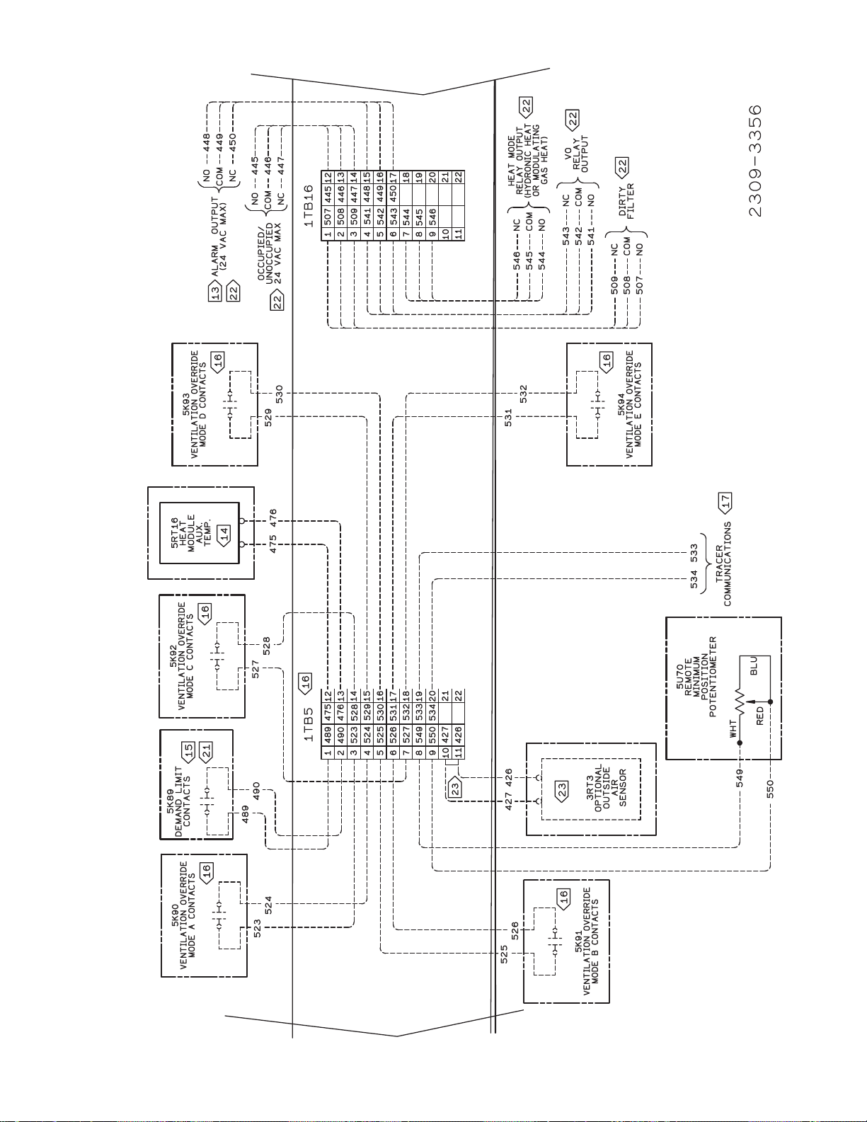
Figure 3-16B
Typical Ventilation Override Binary Output Wiring Diagram for 20 through 130 Ton CV Control Options
Refer to Wiring Notes on page 51
50
Page 52

Field Connection Diagram Notes for 20 through 130 Ton CV or VAV Applications
51
Page 53

Figure 3-17A
Typical Field Wiring Diagram for 20 through 130 Ton VAV Control Option
Refer to Wiring Notes on page 51
52
Page 54

Figure 3-17B
Typical Ventilation Override Binary Output Wiring Diagram for 20 through 130 Ton VAV Control Options
Refer to Wiring Notes on page 51
53
Page 55
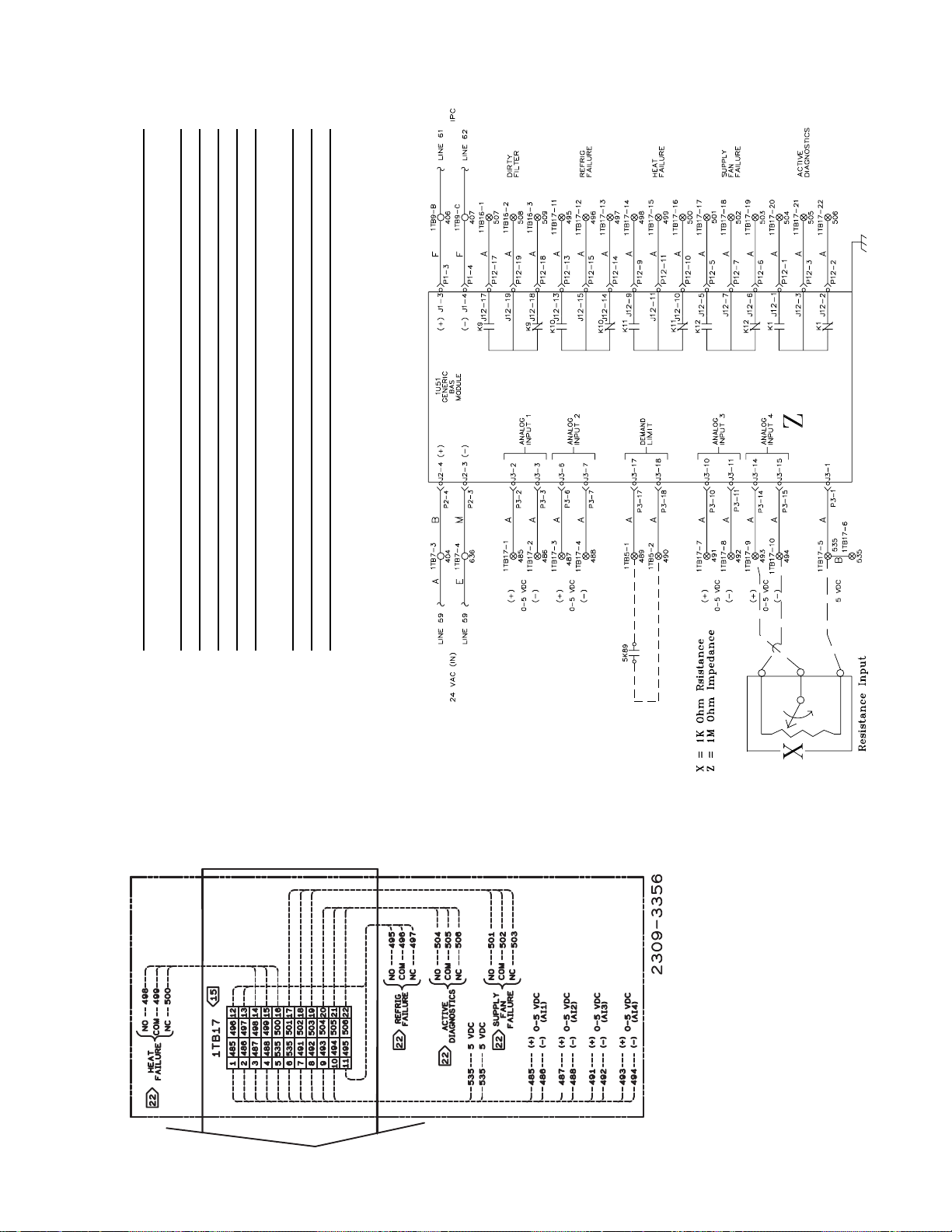
GBAS Voltage vs Setpoint
Unit Type
VAV CV SETPOINT Input Voltage* Setpt Range
x x Unoccupied Zone Cooling Setpoint 0.5 to 4.5 vdc 50°F to 90°F
x Occupied Zone Cooling Setpoint 0.5 to 4.5 vdc 50°F to 90°F
x x Occupied Zone Heating Setpoint 0.5 to 4.5 vdc 50°F to 90°F
x S/A Cooling Setpoint 0.5 to 4.5 vdc 40°F to 90°F
x S/A Heating Setpoint
(VAV Hydro Only) 0.5 to 4.5 vdc 40°F to 180°F
x x Space Static Pressure Setpoint 0.5 to 4.5 vdc 0.03 to 0.3 IWC
x Supply Duct Static Pressure Setpoint 0.5 to 4.5 vdc 0.00 to 5.0 IWC
Voltage Inputs less than 0.5 will be interpreted as 0.5 vdc.
Voltage Inputs higher than 4.5 will be interpreted as 4.5 vdc.
* The actual inputted value will be displayed on the Human Interface.
Figure 3-18
Typical GBAS Analog Input Wiring Diagram for 20 through 130 Ton CV & VAV Control Options
Refer to Wiring Notes on page 51
54
Page 56

Table of Contents
Section One
About The Manual ............................................................... 2
Literature Change History ................................................ 2
Overview of Manual ......................................................... 2
Section Two
General Information ............................................................. 4
Model Number Description .............................................. 4
Hazard Identification ........................................................ 6
Commonly Used Acronyms ............................................. 6
Unit Description ................................................................ 6
Input Devices & System Functions .................................. 8
Constant Volume & Variable Air Volume Units ................ 8
Constant Volume (CV) Units .......................................... 10
Variable Air Volume (VAV) Units .................................... 11
Space Temperature Averaging .......................................12
Unit Control Modules (UCM) ..........................................12
Section Three
Installation .......................................................................... 14
Unit Inspection ............................................................... 14
Storage ........................................................................... 14
Unit Clearances .............................................................14
Unit Dimensions & Weight Information .......................... 14
Roof Curb and Ductwork ............................................... 22
Pitch Pocket Location .................................................... 23
Unit Rigging & Placement .............................................. 23
General Unit Requirements ........................................... 25
Main Electrical Power Requirements............................. 25
Field Installed Control Wiring ......................................... 25
Requirements for Electric Heat Units ............................ 25
Requirements for Gas Heat ...........................................25
Requirements for Hot Water Heat (SLH_) ..................... 25
Requirements for Steam Heat (SSH_) .......................... 26
O/A Pressure Sensor and Tubing Installation ............... 26
Condensate Drain Connection....................................... 27
Shipping Fasteners ........................................................27
O/A Sensor & Tubing Installation ...................................31
Units with Statitrac™; .................................................... 31
Gas Heat Units (SFH_) ..................................................32
Connecting the Gas Supply Line to the Furnace
Gas Train ........................................................................32
Flue Assembly Installation ............................................. 34
Hot Water Heat Units (SLH_) ........................................ 34
Steam Heat Units (SSH_) ..............................................35
Disconnect Switch External Handle ............................... 38
Electric Heat Units (SEH_) ............................................ 38
Main Unit Power Wiring ................................................. 38
Disconnect Switch Sizing (DSS) ....................................44
Field Installed Control Wiring ......................................... 45
Controls using 24 VAC ................................................... 45
Controls using DC Analog Input/Outputs ....................... 45
Constant Volume System Controls ................................45
Variable Air Volume System Controls ............................ 46
Constant Volume or Variable Air Volume System
Controls ..........................................................................46
Section Four
Unit Start-Up ......................................................................55
Cooling Sequence of Operation .................................... 55
Gas Heating Sequence of Operation ............................. 56
Fenwal Ignition System .................................................. 56
Honeywell Ignition System ............................................. 56
Modulating Gas Sequence of Operation ....................... 57
Flame Failure ................................................................. 57
Electric Heat Sequence of Operation ............................ 58
Wet Heat Sequence of Operation.................................. 58
Electrical Phasing .......................................................... 59
Voltage Supply and Voltage Imbalance ......................... 60
Service Test Guide for Component Operation ............... 61
Verifying Proper Fan Rotation ....................................... 63
If all of the fans are rotating backwards;........................ 63
System Airflow Measurements ...................................... 63
Constant Volume Systems............................................. 63
Variable Air Volume Systems ......................................... 65
Exhaust Airflow Measurement ....................................... 66
TraqTM Sensor Airflow Measurement ........................... 66
Economizer Damper Adjustment ................................... 80
Compressor Start-Up .....................................................82
Compressor Operational Sounds .................................. 83
Thermostatic Expansion Valves..................................... 93
Charging by Subcooling ................................................. 93
Low Ambient Dampers ................................................... 93
Electric, Steam and Hot Water Start-Up ........................ 94
Gas Furnace Start-Up .................................................... 94
Two Stage Gas Furnace ................................................ 95
Full Modulating Gas Furnace......................................... 97
Limited Modulating Gas Furnace ................................... 98
Final Unit Checkout ........................................................ 99
Section Five
Service & Maintenance.................................................... 100
Fan Belt Adjustment ..................................................... 104
Scroll Compressor Replacement ................................. 105
VFD Programming Parameters ................................... 106
Monthly Maintenance ................................................... 107
Filters............................................................................ 107
Cooling Season ............................................................107
Heating Season............................................................ 108
Coil Cleaning ................................................................ 108
Final Process ............................................................... 109
Index ............................................................................... 111
UV ................................................................................... 114
Warranty ......................................................................... 114
Page 57
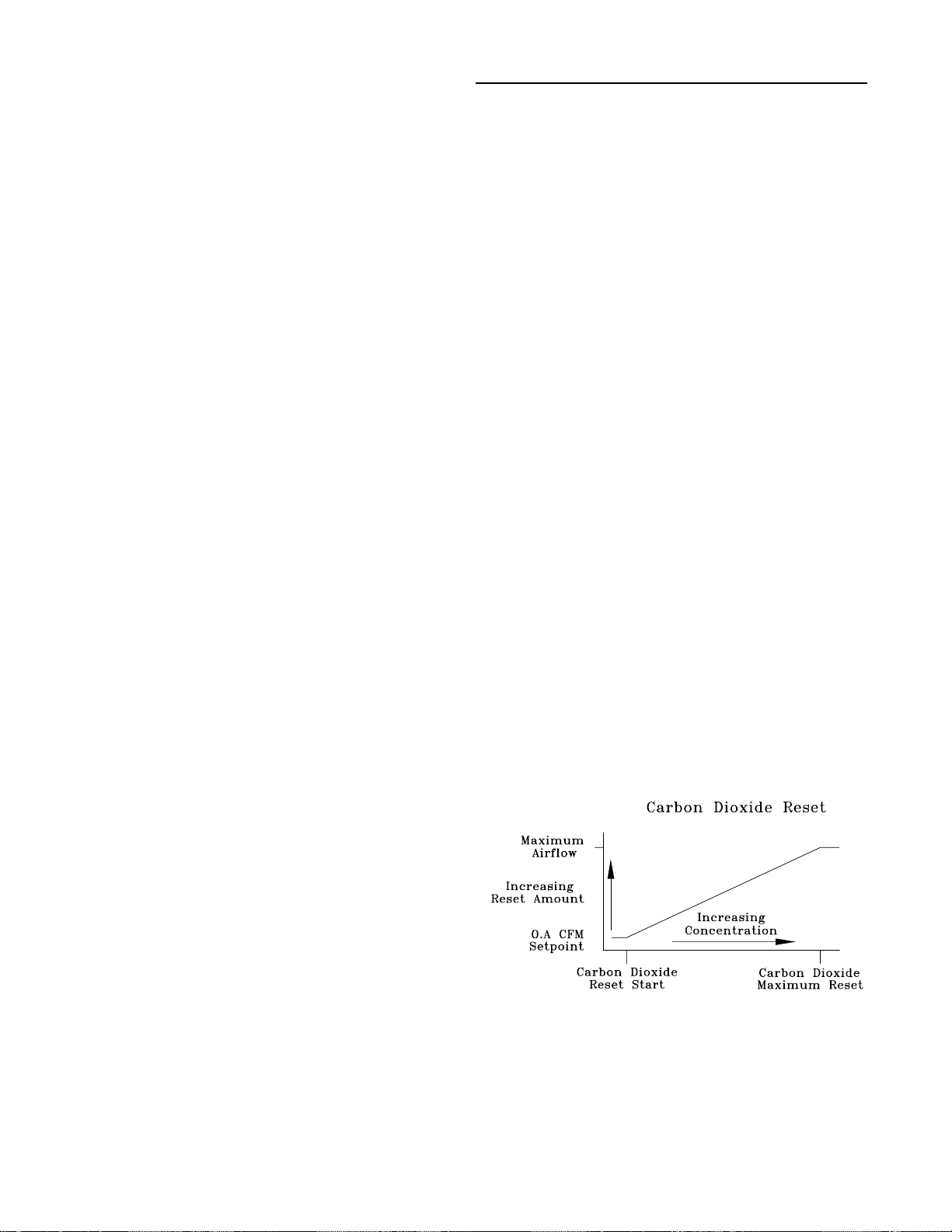
Unit Start-Up
Cooling Sequence of Operation
Time delays are built into the controls to increase reliability
and performance by protecting the compressors and maximizing unit efficiency.
Sequence of Operation
Compressor Crankcase Heaters
Each compressor is equipped with a crankcase heater and
is controlled by a 600 volt auxiliary switch on the compressor contactor. The proper operation of the crankcase heater
is important to maintain an elevated compessor oil temperature during the "Off" cycle to reduce oil foaming during compressor starts.
When the compressor starts, the sudden reduction in crankcase pressure causes the liquid refrigerant to boil rapidly
causing the oil to foam. This condition could damage compressor bearings due to reduced lubrication and could
cause compressor mechanical failures.
When power has been "Off" for an extended period, allow
the crankcase heater to operate a minimum of 8 hours before starting the unit.
Units without an Economizer
Upon entering an "occupied" mode of operation, the RTM
receives input from the remote panel to start the supply fan.
For constant volume applications, the RTM supply fan contacts K2 close which energizes the supply fan contactor
1K16. Units equipped with Inlet Guide Vanes (IGV), the fan
is delayed until the inlet guide vanes are driven to the full
closed position. When the supply fan starts, the fan proving
switch (3S68) closes, signaling the RTM that airflow has
been established. Inlet Guide Vanes will begin to drive open
(if equipped), or the VFD will begin to ramp the fan, (if
equipped).
When a cooling request is sent to the RTM from a zone
temperature sensor, the RTM evaluates the operating condition of the system using the supply air temperature input
and the outdoor temperature input before sending the request to the SCM/MCM. Once the request is sent to the
SCM/MCM, the compressor module checks the compressor
protection circuit before closing "Stage 1" (K10 on SCM or
K11 on MCM). After the first functional stage has started,
the compressor module monitors the saturated refrigerant
temperature and closes the condenser fan output contact
"1A", when the saturated refrigerant temperature rises
above the "lower limit" setpoint.
door conditions are suitable for cooling (temperature and
humidity are within specified setpoints), the RTM will attempt to maintain the zone temperature without using any
compressors. If the zone temperature can not be maintained within the setpoint deadband, the RTM sends a cooling request to the SCM/MCM. The compressor module
checks the compressor protection circuit before closing
"Stage 1" (K10 on SCM or K11 on MCM). After the first
functional stage has started, the compressor module monitors the saturated refrigerant temperature and closes the
condenser fan output contact "1A", when the saturated refrigerant temperature rises above the "lower limit" setpoint.
TM
Units with Traq
The fresh air enters the unit through the Traq
Sensor
TM
Sensor assembly and is measured by velocity pressure flow rings.
The velocity pressure flow rings are connected to a pressure transducer/solenoid assembly. The solenoid is used for
calibration purposes to compensate for temperature swings
that could affect the transducer. The Ventilation Control
Module (VCM) utilizes the velocity pressure input, the RTM
outdoor air temperature input, and the minimum outside air
CFM setpoint to modify the volume (CFM) of fresh air entering the unit as the measured airflow deviates from setpoint.
When the optional temperature sensor is installed and the
Preheat function is enabled, the sensor will monitor the
combined (averaged) fresh air and return air temperatures.
As this mixed air temperature falls below the Preheat Actuate Temperature Setpoint, the VCM will activate the preheat
binary output used to control a field installed heater. The
output will be deactivated when the temperature rises 5
above the Preheat Actuate Temperature Setpoint.
When the optional CO2 sensor is installed and the CO2 Reset is enabled, as the CO
the CO
mum outside air CFM setpoint to increase the amount of
Reset Start Value, the VCM will modify the mini-
2
concentration increases above
2
fresh air entering the unit. The setpoint will be adjusted upward until the CO
maximum effective (reset) setpoint value for fresh air enter-
Maximum Reset Value is reached. The
2
ing the unit is limited to the systems operating CFM. As the
concentration decreases, the effective (reset) setpoint
CO
2
value is adjusted downward toward the minimum outside air
CFM setpoint.
Units with an Economizer
Upon entering an "occupied" mode of operation, the RTM
receives input from the remote panel to start the supply fan.
For constant volume applications, the RTM supply fan contacts K2 close which energizes the supply fan contactor
1K16. Units equipped with Inlet Guide Vanes (IGV), the fan
is delayed until the inlet guide vanes are driven to the full
closed position. When the supply fan starts, the fan proving
switch (3S68) closes, signaling the RTM that airflow has
been established. The RTM opens the economizer dampers
to the specified "minimum position".
When a cooling request is sent to the RTM from the zone
temperature sensor, the RTM evaluates the operating condition of the system using the supply air temperature input
and the outdoor temperature input before sending the request to the SCM/MCM for mechanical cooling. If the out-
Frostat
TM
Control
The compressor module utilizes an evaporator temperature
sensor (3RT14 & 15), mounted on the suction line of each
circuit, to protect the evaporator from freezing. If the evaporator temperature approaches the specified setpoint, adjustable between 25 F and 35 F, the compressor(s) will be
cycled "off". The compressors will not be allowed to restart
until the evaporator temperature has risen 10 F above the
specified cutout temperature and the compressor(s) have
been off for a minimum of three minutes.
55
Page 58

Lead/Lag Operation
When Lead/Lag is enabled, each time the system cycles after having stages 1 and 2 "On", "Stage 2" (K11 on SCM or
K3 on MCM) and the corresponding condenser fan output
"2A" will start first. The compressor module cycles the
compressors "On" and "Off" to keep the zone temperature
within the cooling setpoint deadband. The condenser fans
are cycled "On" and "Off" to maintain the saturated refrigerant temperature within the specified controlband.
Units equipped with 100% modulating exhaust
The exhaust dampers are controlled through an Exhaust/
Comparative Enthalpy Module (ECEM). The ECE module
receives input form a space transducer and modulates the
exhaust dampers to maintain the space pressure to within
the specified setpoint controlband.
Gas Heating Sequence of Operation
Standard Two Stage Gas Furnace
The control system for the rooftop units are wired to ensure
that the heating and cooling do not occur simultaneously.
Refer to the wiring diagram that shipped with the unit while
reviewing the following sequence of operation.
Fenwal Ignition System
(235 & 350 MBH Natural Gas)
When a heating requirement exists, the Rooftop Module
(RTM) starts the supply fan and sends a request for heat to
the Heat Module. The Heat Module closes K11 contacts
and starts the combustion blower motor (4B11). The combustion blower motor starts on low speed through the normally closed combustion fan relay (4K33) contacts. The
heat module also closes K12 contacts. Power is then supplied through the supply air flow switch (4S38), the combustion air flow switch (4S25), the high limit cutout (4S26),
and finally through the normally closed sequencing time
delay (4DL6) contacts to the pre-purge time delay relay
(4DL5). The Fenwal ignition control board (4U18), the 60
second sequencing time delay relay (4DL6), and the combustion blower relay (4K33) will not energize until the prepurge timer (4DL5) closes its contacts. Once closed, the
Fenwal ignition control board (4U18) energizes the 1st
stage solenoid on the gas valve (4L15), the interlock relay
(4K32), and the ignition electrode (4E1). A second set of
normally open timed closed contacts on the pre-purge
timer (4DL5) are wired into the 1U50 heat fail input in series with a normally closed set of contacts on the interlock
relay (4K32). When the commonly open contacts on the interlock relay (4K32) closes, it will maintain an electrical
path for the ignition control board (4U18) and subsequent
controls after the pre-purge timer (4DL5) is de-energized
by the sequencing time delay relay (4DL6). The normally
open contacts on the pre-purge time delay relay (4DL5)
will open in the 1U50 heat fail input, preventing the Heat
Fail diagnostic.
Unit Start-Up (Continued)
If the flame rod (4U19) does not detect a flame at the time
of an initial call for heat or detects a loss of flame during
operation, it will de-energize the gas valve and the interlock relay (4K32). The Fenwal ignition control board
(4U18) will lockout automatically. If a flame failure occurs
prior to the sequencing time delay relay (4DL6) opening its
contacts which de-energizes the pre-purge timer (4DL5),
the sequencing time delay relay (4DL6) will complete its
timing. When completed, the pre-purge time delay relay
(4DL5) is de-energized, opening its contacts which disconnects power to the ignition control board (4U18), the sequencing time delay relay (4DL6), and the 2nd stage solenoid on the gas valve (4L15). Once power is removed from
the ignition control board, it will reset automatically. If a call
for heat still exists, after approximately 60 seconds, the
contacts for the sequencing time delay relay (4DL6) will
close, powering the pre-purge time delay circuit while timing open to the combustion blower relay (4K33) and the
2nd stage solenoid on the gas valve (4L15). The pre-purge
time delay relay (4DL5) will initiate another ignition sequence. The combustion blower motor will continue to operate as long as a heating requirement exists and the service switch (4S24) is "On".
Once the heating demand has been satisfied, the combustion blower motor and the ignition control board is de-energized.
Propane Gas
Units that operate on propane gas have one additional control that affects the combustion blower motor operation
when a heating demand has been initiated or satisfied.
The post purge time delay relay (4DL4) is installed which
delays the starting of the combustion blower by approximately 60 seconds. Once it has timed out, the combustion
blower motor will start, closing the combustion air flow
switch (4S25). The ignition sequence will follow the same
sequence from the combustion airflow switch (4S25) to the
subsequent controls as a natural gas system.
Once the heating demand has been satisfied, the Fenwal
ignition control board (4U18) and the post purge time delay
relay (4DL4) is de-energized. The combustion blower motor
will continue to operate for approximately 15 seconds to
purge the heat exchanger on the "Off" cycle.
Honeywell Ignition System
(500 & 850 MBH Natural Gas)
When a heating requirement exists, the Rooftop Module
(RTM) starts the supply fan and sends a request for heat to
the Heat Module. The Heat Module closes K1 contacts and
starts the combustion blower motor (4B11). The combustion
blower motor starts on low speed through the normally
closed combustion blower relay (4K33) contacts.
The ignition electrode (4E1) will spark continuously for 4.7
seconds in an attempt to establish a flame. The flame is
proven by the flame rod (4U19). The system will operate in
the low heat mode until there is an additional call for heat
established by closing the K1 contacts on the Heat Module.
The 60 second sequencing time delay relay (4DL6) will
energize the combustion blower relay (4K33) which
switches the combustion blower motor to high speed and
energizes the 2nd stage solenoid on the gas valve (4L15).
The supply airflow switch (4S38) and the combustion air
switch (4S25) closes. Power is applied through the high
limit cutout (4S26) to the Honeywell ignition control board
(4U18). The ignition control board (4U18) starts a pre-purge
timing cycle. At the end of the pre-purge cycle, the ignition
transformer (4T7) and the pilot solenoid valve (4L9) are energized. This starts a 10 second trial for pilot ignition. When
the pilot flame is established and sensed by the flame sensing rod (4U19), stage 1 of the main gas valve (4L7) and the
60 seconds sequencing time delay relay (4DL6) is energized.
56
Page 59

Unit Start-Up (Continued)
The system will operate in the low heat mode until there is
an additional call for heat is established by closing the K3
contacts on the Heat Module.
On Variable Air Volume systems, the sequencing time delay
relay (4DL6) will energize the combustion blower motor relay (4K33) which switches the combustion blower motor to
high speed and energizes the 2nd stage solenoid on the
gas valve (4L7) after approximately 60 seconds.
If the flame rod (4U19) does not detect a pilot flame within
the 10 second trial for ignition period, the control will lockout. If a flame failure occurs during operation, the gas valve
(4L7), the sequencing time delay relay (4DL6), and the
combustion blower relay (4K33) is de-energized. The system will purge and attempt to relight the pilot. If a flame is
not detected after this attempt, the Honeywell ignition control (4U18) will lock out. The combustion blower motor will
continue to operate as long as a heating demand exists and
the system switch (4S24) is "On".
Once the heating demand has been satisfied, the combustion blower and the Honeywell ignition control board (4U18)
is de-energized.
Propane Gas
Units that operate on propane gas after 1990 have two (2)
additional controls that affect the combustion blower motor
operation and the sequence of the gas valve operation.
With the post purge time delay relay (4DL4), the additional
service switch (4S24), and the additional 115 volt control relay (4K31) installed, the sequence of operation is as follows:
Power is applied to the Honeywell ignition control board
(4U18) through the high limit switch (4S26). The Honeywell
ignition control board (4U18) will sequence through its prepurge timing and pilot ignition sequence to The post purge
time delay relay (4DL4) delays the starting of the combustion blower motor by approximately 60 seconds. Once the
timing has elasped, the combustion blower motor will start,
closing the combustion air switch (4S25).
Energize the control relay (4K31) and the sequence time
delay relay (4DL6). 24 volts is applied from the new service
switch (4S24) through the normally open control relay
(4K31) contacts to energize the 1st stage solenoid on the
gas valve (4L7).
On an additional call for heat, the K3 contacts on the Heat
Module will close to energize the combustion blower relay
(4K33) which switches the combustion blower motor to high
speed and closes its normally open contacts allowing 24
volts to energize the 2nd stage on the gas valve (4L7).
Once the heating demand has been satisfied, the
Honeywell ignition control board (4U18) and the post purge
time delay relay (4DL4) is de-energized. The combustion
blower motor will continue to operate for approximately 15
seconds to purge the heat exchanger on the "Off" cycle.
Modulating Gas Sequence of Operation
Full and Limited Modulating Gas Furnace
eration. As you review the sequence of operations, keep the
following in mind:
1. The furnace will not light unless the manual gas valves
are open and the control circuit switch 4S24 is closed.
2. The control systems are wired to ensure that heating and
cooling cannot occur simultaneously.
3. The unit supply fans must run continuously so air flow
switch 4S38 will stay closed.
4. Modulating Gas heat is available during both occupied
and unoccupied operation.
Whenever there is a call for heat, 1U50-K1 energizes and
combustion blower motor 4B11 begins to operate at High
speed on the 850 and 1000 MBH heaters. The blower will
operate on low speed for the 500 MBH. A relay 4K119 in
parallel with the main gas valve actuator control output, insures the actuator will be open prior to proof of flame. This
will force the combustion air actuator 4U82 to the open position, causing the auxiliary switch on 4U82 to close. This
insures complete purging of the combustion chamber during
the 60 second purge cycle.
Ignition control IC board 4U18 will not energize, however,
unless the supply air flow switch 4S38, combustion air flow
switch 4S25, high limit cutout 4S26, the auxiliary switch on
combustion air actuator 4U82 and the proof of closure
switch on gas valve 4L22 are closed. These are all part of
the safety interlock system.
With all these conditions satisfied, the IC board energizes
and initiates an internal 60 second pre-purge time delay.
When the pre-purge period expires, 4U18 energizes both
the ignition transformer 4T7 and solenoid 4L9 on the intermittent pilot valve. At that point, 4U18 gives electrode 4E1
approximately 10 seconds to establish a pilot flame. (The
presence of this flame is proven by flame rod 4U19.)
If 4U18 does not detect a pilot flame at the end of this pe-
riod, it will shut down and lock out the ignition / combustion
circuit.
If the pilot is ignited within 10 seconds, the IC board de-energizes the ignition transformer 4T7 and electrode 4E1. At
this point, relay 4K119 will energize, starting the combustion air actuator and the furnace. The feedback signal from
the discharge temperature sensor will cause the modulating
output from the heat module to change the damper position
as required to maintain the outlet temperature within the desired band.
Flame Failure
In the event that IC board 4U18 loses the “proof-of-flame”
input signal during furnace operation, it will make one attempt at reignite. If a flame is not reestablished within the
10 second trial period, 4U18 will shut down and lock out the
ignition /combustion control circuit. (Combustion blower motor 4B11 continues to run as long as a heating requirement
exists and control circuit switch 4S24 is ON.)
The control system for the rooftop units are wired to ensure
that the heating and cooling do not occur simultaneously.
Refer to the modulating heat wiring diagram that shipped
with the unit while reviewing the following sequence of op-
Once locked out on flame failure, the IC board will not reactivate the ignition/combustion control circuit until it is reset
manually. To do this, press the reset button on the front of
the IC board case.
57
Page 60

Unit Start-Up (Continued)
A set of relay contacts are available for external use for
heat fail (Information Only).
Note: The modulating gas heaters are factory
adjusted for the proper air/gas ratio at minimum
and nameplate rated firing MBH for most areas in
the country.
Electric Heat Sequence of Operation
The control system for the rooftop units are wired to ensure
that the heating and cooling do not occur simultaneously.
Refer to the electric heat wiring diagrams that shipped with
the unit while reviewing the following sequence of operation. As you review the sequence of operations, remember
these points:
Whenever there is a call for heat, 1U50-K1 energizes. This
energizes HEAT 1 contactors 4K34 and 4K35 which, in
turn, energize two of the six 4HR3 heating elements.
Note: Electric heater 4HR3 will only energize if both
of the heat section’s high limit safety controls—
4S27 and 4S33—are closed.
1. High limit Switch 4S27 will trip if exposed to a temperature of 133
perature falls to 110
box-side of the electric heat element assembly.
2. Linear high limit 4S33 is encased in a capillary that extends across the unit’s supply air opening, and is anchored near the bottom of the heat section control box.
It is designed to trip if the temperature across any 6"
span of the capillary exceeds 185
Table 5-1.
The HEAT 2 (4K36, 4K37) and HEAT 3 (4K38, 4K39) con-
tactors are not energized unless the 1st stage bank of heating elements already operating are not satisfying the heating load.
+ 5 F, and reset automatically once the tem-
+ 5 F. It is mounted on the control-
+ 10 F. Refer to
Wet Heat Sequence of Operation
Electrical circuitry for units with steam or hot water heat is
limited to the connections associated with the modulating
valve actuator (4U15) and the freezestat (4S12).
Like the furnaces described earlier, SL/SH control systems
are wired to ensure that simultaneous heating and cooling
do not occur. The supply fan will cycle "On" and "Off" with
each call for heat during both an occupied and unoccupied
period.
Whenever there is a call for heat, 1U50-K3 energizes. This
allows a modulated voltage signal to be sent to the “Wet”
heat actuator 4U15. Depending on the value of this signal,
4U15 regulates the flow of steam or hot water through the
coil by positioning the valve stem at some point between
fully closed (6 VDC) and fully open (8.5 VDC).
Freeze Protection
A freezestat (4S12) is mounted inside the heat section of
SLH_ and SSH_ units to prevent the “wet” heat coil from
freezing during the "Off" cycle.
If the temperature of the air leaving the heating coils falls to
40 F, the freezestat's normally-open contacts close, completing the heat fail circuit on the UCM. When this occurs:
a. The supply fan is turned "Off".
b. "Wet” heat actuator 4U15 fully opens to allow hot
water or steam to pass through the heating coil and
prevent freeze-up.
c. A "Heat Fail" diagnostic is displayed on the Human
Interface LCD screen.
For heating control settings and time delay specifications,
refer to Table 5-1.
58
Page 61

Use the checklist provided below in conjunction with the
“General Unit Requirement" checklist” to ensure that the
unit is properly installed and ready for operation. Be sure to
complete all of the procedures described in this section before starting the unit for the first time.
[ ] Turn the field supplied disconnect switch, located up-
stream of the rooftop unit, to the "Off" position.
WARNING
Hazardous Voltage!
Disconnect all electric power, including remote disconnects before servicing. Follow proper lockout/tagout
procedures to ensure the power can not be inadvertently energized. Failure to disconnect power before servicing could result in death or serious injury.
[ ] Turn the 115 volt control circuit switch 1S1 to the "Off"
position. It is located in the secondary of the 1T1 transformer.
[ ] Turn the 24 volt control circuit switch 1S70 to the "Off"
position. It is located in the secondary of the 1T2 & 1T3
transformers.
[ ] Turn the "System" selection switch (at the Remote
Panel) to the "Off" position and the "Fan" selection
switch (if Applicable) to the "Auto" or "Off" position.
[ ] Check all electrical connections for tightness and "point
of termination" accuracy.
Unit Start-Up (Continued)
Units with Low Ambient option without HGBP - 0 F
Units with Low Ambient option with HGBP - +10 F
Note: To prevent compressor damage due to no
refrigerant flow, do not pump the system down with
the compressor(s) below 7 PSIG under any
circumstance.
[ ] Check the supply fan belts for proper tension and the
fan bearings for sufficient lubrication. If the belts require
adjustment, or if the bearings need lubricating, refer to
the Service/Maintenance section of this manual for instructions.
[ ] Inspect the interior of the unit for tools and debris. Install
all panels in preparation for starting the unit.
Electrical Phasing
Unlike traditional reciprocating compressors, scroll compressors are phase sensitive. Proper phasing of the electrical supply to the unit is critical for proper operation and reliability.
The compressor motor is internally connected for clockwise
rotation with the incoming power supply phased as
A, B, C.
Proper electrical supply phasing can be quickly determined
and corrected before starting the unit by using an instrument such as an Associated Research Model 45 Phase Sequence Indicator and following the steps below:
[ ] Verify that the condenser airflow will be unobstructed.
[ ] Check the compressor crankcase oil level. Oil should be
visible in the compressor oil sight glass. The oil level
should be 1/2 to 3/4 high in the sight glass with the compressor "Off".
[ ] Verify that the compressor discharge service valve and
the liquid line service valve is back seated on each circuit.
CAUTION
Compressor Damage!
Do not allow liquid refrigerant to enter the suction line.
Excessive liquid accumulation in the liquid lines may
result in compressor damage.
Compressor service valves must be fully opened before
start-up (suction, discharge, liquid line, and oil line).
Do not start the unit in the cooling mode if the ambient temperature is below the following minimum recommended operating temperatures:
Standard unit with or without HGBP -
+55 F for 20 & 40 Ton
+50 F for 25 & 30 Ton
+45 F for 70 thru 130 Ton
+40 F for 55 Ton
+35 F for 50 Ton
+30 F for 60 Ton
[ ] Turn the field supplied disconnect switch that provides
power to terminal block 1TB1 or to the unit mounted disconnect switch 1S14 to the "Off" position.
[ ] Connect the phase sequence indicator leads to the ter-
minal block or unit mounted disconnect switch as follows;
Phase Sequence Unit Power
Leads Terminal
Black (phase A) L1
Red (phase B) L2
Yellow (Phase C) L3
[ ] Close the disconnect switch or circuit protector switch
that provides the supply power to the unit's terminal
block 1TB1 or the unit mounted disconnect switch 1S14.
WARNING
Hazardous Voltage!
Disconnect all electric power, including remote disconnects before servicing. Follow proper lockout/tagout
procedures to ensure the power can not be inadvertently energized. Failure to disconnect power before servicing could result in death or serious injury.
HIGH VOLTAGE IS PRESENT AT TERMINAL BLOCK
1TB1 OR UNIT DISCONNECT SWITCH 1S14.
59
Page 62
Unit Start-Up (Continued)
[ ] Observe the ABC and CBA phase indicator lights on the
face of the sequencer. The ABC indicator light will glow
if the phase is ABC. If the CBA indicator light glows,
open the disconnect switch or circuit protection switch
and reverse any two power wires.
[ ] Restore the main electrical power and recheck the
phasing. If the phasing is correct, open the disconnect
switch or circuit protection switch and remove the phase
sequence indicator.
Voltage Supply and Voltage Imbalance
Voltage Supply
Electrical power to the unit must meet stringent requirements for the unit to operate properly. Measure each leg
(phase-to-phase) of the power supply. Each reading must
fall within the utilization range stamped on the unit nameplate. If any of the readings do not fall within the proper tolerances, notify the power company to correct this situation
before operating the unit.
WARNING
Live Electrical Components!
During installation, testing, servicing and troubleshooting of this product, it may be necessary to work with live
electrical components. Have a qualified licensed electrician or other individual who has been properly trained in
handling live electrical components perform these
tasks. Failure to follow all electrical safety precautions
when exposed to live electrical components could result
in death or serious injury.
Voltage Imbalance
Excessive three phase voltage imbalance between phases
will cause motors to overheat and eventually fail. The maximum allowable voltage imbalance is 2%. Measure and
record the voltage between phases 1, 2, and 3 and calculate the amount of imbalance as follows:
% Voltage Imbalance = 100 X
AV (Average Voltage) =
V1, V2, V3 = Line Voltage Readings
VD = Line Voltage reading that deviates the farthest from
the average voltage.
Example: If the voltage readings of the supply power
measured 221, 230, and 227, the average volts would
be:
221 + 230 + 227 = 226 Avg.
VD (reading farthest from average) = 221
The percentage of Imbalance equals:
100 X
The 2.2% imbalance in this example exceeds the maximum
allowable imbalance of 2.0%. This much imbalance between phases can equal as much as a 20% current imbalance with a resulting increase in motor winding temperatures that will decrease motor life. If the voltage imbalance
is over 2%, notify the proper agencies to correct the voltage
problem before operating this equipment.
3
226 - 221 = 2.2%
226
AV - VD where;
AV
Volt 1 + Volt 2 + Volt 3
3
60
Page 63

Table 4-1
g
Service Test Guide for Component Operation
COMPONENT COMPONENT CONFIGURATION Occ
BEIN G TESTED Supply Exhaust Condense r Heat Stages
* COMPRESSOR
20 thru 30 Ton
A Off Off A-Off/B-On Off Off Off K10-Off K11-On N/A N/A Closed Closed Closed 0% Default
B Off Off A-On/B-Off Off Off Off K10-On K11-Off N/A N/A Closed Closed Closed 0% Default
40 thru 60 Ton
1A Off Off 1A-Off/1B-On Off Off Off K11-Off K3-Off K12-On K4-Off Closed Closed Clos ed 0% Default
1B Off Off 1A-On/1B-Off Off Off Off K11-On K3-Off K12-Off K4-Off Closed Closed Closed 0% Default
2A Off Off 1A-Off/1B-Off Off Off Off K11-Off K3-Off K12-Off K4-On Closed Closed Closed 0% Default
2B Off Off 1A-Off/1B-Off Off Off Off K11-Off K3-On K12-Off K4-Off Closed Closed Closed 0% Default
70 thru 105 Ton
1A & 1B Off Off 1A-Off/1B-On Off Off Off K11-Off K3-Off K12-On K4-Off Closed Close d Closed 0% Default
1C Off Off 1A-On/1B-Off Off Off Off K11-On K3-Off K12-Off K4-Off Closed Closed Closed 0% Default
2A & 2B Off Off 1A-Off/1B-Off Off Off Off K11-Off K3-Off K12-Off K4-On Closed Closed Closed 0% Default
2C Off Off 1A-Off/1B-Off Off Off Off K11-Off K3-On K12-Off K4-Off Closed Closed Clos ed 0% Default
115 thru 130 Ton
1A & 1B Off Off 1A-Off/1B-On Off Off Off K11-Off K3-Off K12-On K4-Off Closed Close d Closed 0% Default
1C & 1D Off Off 1A-On/1B-Off Off Off Off K11-On K3-Off K12-Off K4-Off Closed Closed Closed 0% Default
2A & 2B Off Off 1A-Off/1B-Off Off Off Off K11-Off K3-Off K12-Off K4-On Closed Closed Closed 0% Default
2C & 2D Off Off 1A-Off/1B-Off Off Off Off K11-Off K3-On K12-Off K4-Off Closed Closed Closed 0% Default
** CONDENSER FANS
20 Ton
A-2B1 Off Off A-On/B-Off Off Off Off Off Off Off Off Closed Closed Closed 0% Default
B-2B2 Off Off A-Off/B-On Off Off Off Off Off Off Off Closed Close d Closed 0% Default
25 - 30 Ton
A-2B1 Off Off A-On/B-Off Off Off Off Off Off Off Off Closed Closed Closed 0% Default
B-2B2/2B3 Off Off A-Off/B-On Off Off Off Off Off Off Off Closed Closed Closed 0% Default
40 Ton
1A-2B1 Off Off 1A-On/1B-Off Off Off Off Off Off Off Off Closed Closed Closed 0% Default
1B-2B2 Off Off 1A-Off/1B-On Off Off Off Off Off Off Off Closed Closed Closed 0% Default
2A-2B4 Off Off 1A-Off/1B-Off Off Off Off Off Off Off Off Closed Closed Clos ed 0% Default
2B-2B5 Off Off 1A-Off/1B-Off Off Off Off Off Off Off Off Closed Closed Clos ed 0% Default
50 & 55 Ton
1A-2B1 Off Off 1A-On/1B-Off Off Off Off Off Off Off Off Closed Closed Closed 0% Default
1B-2B2/2B3 Off Off 1A-Off/1B-On Off Off Off Off Off Off Off Closed Closed Closed 0% Default
2A-2B4 Off Off 1A-Off/1B-Off Off Off Off Off Off Off Off Closed Closed Clos ed 0% Default
2B-2B5/2B6 Off Off 1A-Off/1B-Off Off Off Off Off Off Off Off Closed Closed Closed 0% Default
60 thru 75 Ton
1A-2B1 Off Off 1A-On/1B-Off Off Off Off Off Off Off Off Closed Closed Closed 0% Default
1B-2B2/2B3 Off Off 1A-Off/1B-On Off Off Off Off Off Off Off Closed Closed Closed 0% Default
2A-2B4 Off Off 1A-Off/1B-Off Off Off Off Off Off Off Off Closed Closed Clos ed 0% Default
2B-2B5/2B6 Off Off 1A-Off/1B-Off Off Off Off Off Off Off Off Closed Closed Closed 0% Default
Refer to the next pa
Fan Fan Fans 1 2 3 1 2 3 4 Damper Damper IGV Output Relay
2A-Off/2B-Off
2A-Off/2B-Off
2A-Off/2B-On
2A-On/2B-Off 0%
2A-Off/2B-Off
2A-Off/2B-Off
2A-Off/2B-On
2A-On/2B-Off
2A-Off/2B-Off
2A-Off/2B-Off
2A-Off/2B-On
2A-On/2B-Off
2A-Off/2B-Off
2A-Off/2B-Off
2A-On/2B-Off
2A-Off/2B-On
2A-Off/2B-Off
2A-Off/2B-Off
2A-On/2B-Off
2A-Off/2B-On
2A-Off/2B-Off
2A-Off/2B-Off
2A-On/2B-Off
2A-Off/2B-On
e for applicable notes.
Compressor Stage Econo Exhaust VFDUnocc
61
Page 64

Table 4-1 (Continued)
y
f
f
f
f
f
g
g
g
Service Test Guide for Component Operation
COMPONENT COMPONENT CONFIGURATION Occ
BEING TESTED Suppl
(Cont.)
** CONDENSER FANS
90 Ton
1A-2B3/2B14 Off Off 1A-On/1B-Off Off Off Off K11-Off K3-Off K12-On K4-Off Closed Closed Closed 0% Default
1B-2B1/2B2 Off Off 1A-Off/1B-On Off Off Off K11-On K3-Off K12-Off K4-Off Closed Closed Closed 0% Default
2A-2B6/2B13 Off Off 1A-Off/1B-Off Off Off Off K11-Off K3-Off K12-Off K4-On Closed Closed Closed 0% Default
2B-2B4/2B5 Off Off 1A-Off/1B-Off Off Off Off K11-Off K3-On K12-Off K4-Off Closed Closed Closed 0% Default
105 & 115 Ton
1A-2B3/2B14 Off Off 1A-On/1B-Off Off Off Off K11-Off K3-Off K12-On K4-Off Closed Closed Closed 0% Default
1B-2B1/2B2/2B19 Off Off 1A-Off/1B-On Off Off Off K11-On K3-Off K12-Off K4-Off Closed Closed Closed 0% Default
2A-2B6/2B13 Off Off 1A-Off/1B-Off Off Off Off K11-Off K3-Off K12-Off K4-On Closed Closed Closed 0% Default
2B-2B4/2B5/2B15 Off Off 1A-Off/1B-Off Off Off Off K11-Off K3-On K12-Off K4-Off Closed Closed Closed 0% Default
130 Ton
1A-2B3/2B14 Off Off 1A-On/1B-Off Off Off Off Off Off Off Off Closed Closed Closed 0% Default
1B-2B1/2B2 Off Off 1A-Off/1B-On O ff Off Off Off Off Off Off Closed Closed Closed 0% Default
2B19/2 B20 2A-O f f/ 2 B-Off
Exhaust Condenser Heat Stages Compressor Stage Econo Exhaust VFD Unocc
Fan Fan Fans 1 2 3 1 2 3 4 Damper Damper IGV Output Relay
2A-Off/2B-Off
2A-Off/2B-Off
2A-On/2B-Off
2A-Off/2B-On
2A-Off/2B-Off
2A-Off/2B-Off
2A-On/2B-Off
2A-Off/2B-On
2A-Off/2B-Off
2A-2B6/2B13 Off Off 1A-Off/1B-Off Off Off Off Off Off Off Off Closed Closed Closed 0% Default
2B-2B4/2B5 Off Off 1A-Off/1B-Off Off Off Off Off Off Off Off Closed Closed Closed 0% Default
2B15/2 B21 2A-O f f/ 2 B-On
SUPPLY FAN
EXHAUST FAN
GAS HEAT (Full Cap.)
Stage 1 On Off All Off On Off N/A Off Off Off Off Closed Closed 100% 100% Unocc
Stage 2 On Off All Off Off On N/A Off Off Off Off Closed Closed 100% 100% Unocc
Full Modulating On Off All Off 90% Select Off Off Off Off Closed Closed 100% 100% Unocc
(High Fire Adjustment) Open
Full Modulating On Off All Off 5% Select Off Off Off Off Closed Closed 100% 100% Unocc
(Low Fire Adjustment) Open
Limited Modulating On Off All Off 90% Select Off Off Off Off Closed Closed 100% 100% Unocc
(High Fire Adjustment) Open
Limited Modulating On Off All Off 33% Select Off Off Off Off Closed Closed 100% 100% Unocc
(Low Fire Adjustment) Open
ELECTRIC HEAT
Stage 1 On Off All Off On Off Off Off Off Off Off Closed Closed 100% 100% Unocc
Stage 2 On Off All Off Off On Off Off Off Off Off Closed Closed 100% 100% Unocc
Stage 3 On Off All Off Off Off On Off Off Off Off Closed Closed 100% 100% Unocc
Hydronic Heat
Pre - Heater
Fresh Air D a mpers
Exhaust Dampers
* - Compressors for the 20 thru 60 Ton units can operate individually or to
Compressors 1A &1B and compressors 2A & 2B operate simultaneously within their respective circuits on the 70 thru 105 Ton units.
Compressors 1A & 1B, 1C & 1D, 2A & 2B, 2C & 2D operate simultaneously within their respective circuits on 115 and 130 Ton units.
Caution:
** - Condenser fan outputs can operate individually or to
*** - Once the u nit h as s tarted, refe r to the Stat us M enu in the H uman In t erfa ce for the OA CFM.
**** - RTM O CC/UN OC C outpu t in t he Se r vic e Test M o de m ust be in t he unoccupie d mo d e to ope n t he s yst em VAV box es a nd th e
Inlet Guide Vanes or to drive the VFD to 100%.
Do Not operate the compressors for extended periods of time without the conden ser fans, Hi
On Off All Off Off Off Off Off Off Off Off Closed Closed 100% 100% Unocc
Of
On Off All Off On On N/A Off Off Off Off Closed Closed 100% 100% Unocc
On Off All Off On On On Off Off Off Off Closed Closed 100% 100% Unocc
Of
Of
Of
Of
2A-On/2B-Off
Open
On All Off Off Off Off Off Off Off Off Closed 100% 100% 100% Default
Open Open
Open
Open
Open
Open
Open
Open
Open
Off All Off 100% Select Off Off Off Off Closed Closed Closed 0% Default
Off All Off On N/A N/A Off Off Off Off Closed Closed Closed 0% Default
Off All Off Off Off Off Off Off Off Off 100% Closed Closed 0% Default
Open
Off All Off Off Off Off Off Off Off Off 100% 100% Closed 0% Default
Open
ether and in any order while in the SERVICE TEST mode.
h Head Pressure will develope.
ether and in any order while in the SERVICE TEST mode.
62
Page 65

Verifying Proper Fan Rotation
1. Ensure that the "System" selection switch at the remote
panel is in the "Off" position and the "Fan" selection
switch for constant volume units is in the "Auto" position.
(VAV units do not utilize a "Fan" selection input.)
2. Close the disconnect switch or circuit protector switch
that provides the supply power to the unit's terminal
block 1TB1 or the unit mounted disconnect switch 1S14.
3. Tur n the 115 volt control circuit switch 1S1 and the 24
volt control circuit switch 1S70 to the "On" position.
Unit Start-Up (Continued)
WARNING
Hazardous Voltage!
Disconnect all electric power, including remote disconnects before servicing. Follow proper lockout/tagout
procedures to ensure the power can not be inadvertently energized. Failure to disconnect power before servicing could result in death or serious injury.
c. Interchange any two of the field connected main
power wires at the unit terminal block 1TB1 or the
factory mounted disconnect switch 1S14.
4. Open the Human Interface access door, located in the
unit control panel, and press the SERVICE MODE key to
display the first service screen. Refer to the latest edition
of the appropriate SAHF-PTG manual for CV or VAV applications for the SERVICE TEST screens and programming instructions.
5. Use Table 4-1 to program the unit Fans for operation by
scrolling through the displays. All of the Fans (Supply,
Exhaust, and Condenser fans) can be programed to be
"On", if desired. Verify proper fan rotation for VFDs with
bypass.
Refer to Figure 4-1 for the condenser fan locations and
the Human Interface designator.
6. Once the configuration for the Fans is complete, press
the NEXT key until the LCD displays the “Start test in
__Sec.” screen. Press the + key to designate the delay
before the test is to start.
the TEST START key is pressed and the delay designated in this step has elapsed. Press the ENTER key to
confirm this choice.
This service test will begin after
WARNING
Rotating Components!
During installation, testing, servicing and troubleshooting of this product it may be necessary to measure the
speed of rotating components. Have a qualified or licensed service individual who has been properly
trained in handling exposed rotating components, perform these tasks. Failure to follow all safety precautions when exposed to rotating components could result in death or serious injury.
7. Press the TEST START key to start the test. Remember
that the delay designated in step 6 must elapse before
the fans will begin to operate.
8. Check the supply fan and the exhaust fans (if equipped)
for proper rotation. The direction of rotation is indicated
by an arrow on the fan housings. Check the condenser
fans for clockwise rotation when viewed from the top.
If all of the fans are rotating backwards;
Note: Interchanging "Load" side power wires at the
fan contactors will only affect the individual fan
rotation. Ensure that the voltage phase sequence at
the main terminal block 1TB1 or the factory
mounted disconnect switch 1S14 is ABC as
outlined in the "Electrical Phasing" section.
If some of the fans are rotating backwards;
a. Press the STOP key at the Human Interface Module
in the unit control panel to stop the fan operation.
b. Open the field supplied disconnect switch upstream
of the rooftop unit. Lock the disconnect switch in the
open position while working at the unit.
c. Interchange any two of the fan motor leads at the
contactor for each fan that is rotating backwards.
System Airflow Measurements
Constant V olume Systems
1. Ensure that the "System" selection switch at the remote
panel is in the "Off" position and the "Fan" selection
switch for constant volume units is in the "Auto" position.
(VAV units do not utilize a "Fan" selection input.)
2. Close the disconnect switch or circuit protector switch
that provides the supply power to the unit's terminal
block 1TB1 or the unit mounted disconnect switch 1S14.
WARNING
Hazardous Voltage!
Disconnect all electric power, including remote disconnects before servicing. Follow proper lockout/tagout
procedures to ensure the power can not be inadvertently energized. Failure to disconnect power before servicing could result in death or serious injury.
HIGH VOLTAGE IS PRESENT AT TERMINAL BLOCK
1TB1 OR UNIT DISCONNECT SWITCH 1S14.
3. Tur n the 115 volt control circuit switch 1S1 and the 24
volt control circuit switch 1S70 to the "On" position.
a. Press the STOP key at the Human Interface Module
in the unit control panel to stop the fan operation.
b. Open the field supplied disconnect switch upstream
of the rooftop unit. Lock the disconnect switch in the
open position while working at the unit.
4. Open the Human Interface access door, located in the
unit control panel, and press the SERVICE MODE key to
display the first service screen. Refer to the latest edition
of the appropriate SAHF-PTG manual for CV or VAV applications for the SERVICE TEST screens and programming instructions.
63
Page 66

Figure 4-1
Condenser Fan Location with Human Interface Designator
5. Use Table 4-1 to program the Supply Fan for operation
by scrolling through the displays.
6. Once the configuration for the Fan is complete, press the
NEXT key until the LCD displays the “Start test in
__Sec.” screen. Press the + key to designate the delay
before the test is to start.
the TEST START key is pressed and the delay designated in this step has elapsed. Press the ENTER key to
confirm this choice.
This service test will begin after
WARNING
Live Electrical Components!
During installation, testing, servicing and troubleshooting of this product, it may be necessary to work with live
electrical components. Have a qualified licensed electrician or other individual who has been properly trained in
handling live electrical components perform these
tasks. Failure to follow all electrical safety precautions
when exposed to live electrical components could result
in death or serious injury.
7. Press the TEST START key to start the test. Remember
that the delay designated in step 6 must elapse before
the fans will begin to operate.
8. With the system in the SERVICE MODE and the supply
fan rotating in the proper direction, measure the amperage at the supply fan contactor 1K16 & 1K15 (additional
contactor for 90 thru 130 Ton units). If the amperage exceeds the motor nameplate value, the static pressure is
less than design and the airflow is too high. If the amperage is below the motor nameplate value, static pressure
may be too high and CFM may be too low. To determine
the actual CFM (± 5%);
a. Measure the actual fan RPM
b. Calculate the Theoretical BHP
Actual Motor Amps X Motor HP)
Motor Nameplate Amps
c. Plot this data onto the appropriate Fan Performance
Curve in Figure 4-2. Where the two points intersect,
read straight down to the CFM line.
64
Page 67

Use this data to assist in calculating a new fan drive if the
CFM is not at design specifications.
An alternate method with less accuracy is to measure the
static pressure drop across the evaporator coil. This can be
accomplished by;
a. drilling a small hole through the unit casing on each
side of the coil.
Note: Coil damage can occur if care is not taken
when drilling holes in this area.
b. Measure the difference between the pressures at
both locations.
c. Plot this value onto the appropriate pressure drop
curve in Figure 4-3. Use the data in Table 4-2
(Component Static Pressure Drops) to assist in
calculating a new fan drive if the CFM is not at
design specifications.
d. Plug the holes after the proper CFM has been
established.
9. Press the STOP key at the Human Interface Module in
the unit control panel to stop the fan operation.
Variable Air Volume Systems
1. Ensure that the "System" selection switch at the remote
panel is in the "Off" position.
Unit Start-Up (Continued)
lay before the test is to start.
after the TEST START key is pressed and the delay
designated in this step has elapsed. Press the ENTER
key to confirm this choice.
This service test will begin
WARNING
Live Electrical Components!
During installation, testing, servicing and troubleshooting of this product, it may be necessary to work with live
electrical components. Have a qualified licensed electrician or other individual who has been properly trained in
handling live electrical components perform these
tasks. Failure to follow all electrical safety precautions
when exposed to live electrical components could result
in death or serious injury.
7. Press the TEST START key to start the test. Remember
that the delay designated in step 6 must elapse before
the fan will begin to operate.
8. With the IGV's/VFD at 100% and the supply fan operating at full airflow capability, measure the amperage at the
supply fan contactor 1K16 & 1K15 (additional contactor
for 90 through 130 Ton units). If the amperage exceeds
the motor nameplate value, the static pressure is less
than design and the airflow is too high. If the amperage
is below the motor nameplate value, static pressure may
be too high and CFM may be too low. To determine the
actual CFM (± 5%);
a. Measure the actual fan RPM
2. Close the disconnect switch or circuit protector switch
that provides the supply power to the unit's terminal
block 1TB1 or the unit mounted disconnect switch 1S14.
WARNING
Hazardous Voltage!
Disconnect all electric power, including remote disconnects before servicing. Follow proper lockout/tagout
procedures to ensure the power can not be inadvertently energized. Failure to disconnect power before servicing could result in death or serious injury.
HIGH VOLTAGE IS PRESENT AT TERMINAL BLOCK
1TB1 OR UNIT DISCONNECT SWITCH 1S14.
3. Turn the 115 volt control circuit switch 1S1 and the 24
volt control circuit switch 1S70 to the "On" position.
4. Open the Human Interface access door, located in the
unit control panel, and press the SERVICE MODE key to
display the first service screen. Refer to the latest edition
of the appropriate SAHF-PTG manual for CV or VAV applications for the SERVICE TEST screens and programming instructions.
5. Use Table 4-1 to program the following system components for operation by scrolling through the displays;
Supply Fan
Inlet Guide Vanes (100% Open, if applicable)
Variable Frequency Drive (100% Output, if applicable)
RTM Occ/Unocc Output (Unoccupied)
6. Once the configuration for the components is complete,
press the NEXT key until the LCD displays the “Start test
in __Sec.” screen. Press the + key to designate the de-
b. Calculate the Theoretical BHP
Actual Motor Amps X Motor HP
Motor Nameplate Amps
c. Plot this data onto the appropriate Fan Performance
Curve in Figure 4-4. Where the two points intersect,
read straight down to the CFM line.
Use this data to assist in calculating a new fan drive if the
CFM is not at design specifications.
An alternate method with less accuracy is to measure the
static pressure drop across the evaporator coil. This can be
accomplished by;
a. drilling a small hole through the unit casing on each
side of the coil.
Note: Coil damage can occur if care is not taken
when drilling holes in this area.
b. Measure the difference between the pressures at
both locations.
c. Plot this value onto the appropriate pressure drop
curve in Figure 4-3. Use the data in Table 4-2
(Component Static Pressure Drops) to assist in
calculating a new fan drive if the CFM is not at
design specifications.
d. Plug the holes after the proper CFM has been
established.
9. Press the STOP key at the Human Interface Module in
the unit control panel to stop the fan operation.
65
Page 68

Unit Start-Up (Continued)
Exhaust Airflow Measurement
(Optional with all Units)
1. Close the disconnect switch or circuit protector switch
that provides the supply power to the unit's terminal
block 1TB1 or the unit mounted disconnect switch 1S14.
WARNING
Hazardous Voltage!
Disconnect all electric power, including remote disconnects before servicing. Follow proper lockout/tagout
procedures to ensure the power can not be inadvertently energized. Failure to disconnect power before servicing could result in death or serious injury.
HIGH VOLTAGE IS PRESENT AT TERMINAL BLOCK
1TB1 OR UNIT DISCONNECT SWITCH 1S14.
2. Turn the 115 volt control circuit switch 1S1 and the 24
volt control circuit switch 1S70 to the "On" position.
3. Open the Human Interface access door, located in the
unit control panel, and press the SERVICE MODE key to
display the first service screen. Refer to the latest edition
of the appropriate SAHF-PTG manual for CV or VAV applications for the SERVICE TEST screens and programming instructions.
7. With the exhaust dampers open and the exhaust fan operating at full airflow capability, measure the amperage at
the exhaust fan contactor 1K17. If the amperage exceeds the motor nameplate value, the static pressure is
less than design and airflow is too high. If the amperage
is below the motor nameplate value, static pressure may
be too high and CFM may be too low. To determine the
actual CFM (± 5%);
a. Measure the actual fan RPM
b. Calculate the Theoretical BHP
Actual Motor Amps X Motor HP
Motor Nameplate Amps
Use Tables 4-3 & 4-4 to calculate a new fan drive if the
CFM is not at design specifications.
8. Press the STOP key at the Human Interface Module in
the unit control panel to stop the fan operation.
TraqTM Sensor Airflow Measurement
(Optional with all units equipped with an economizer)
1. Open the Human Interface access door, located in the
unit control panel, and press the SERVICE MODE key to
display the first service screen. Refer to the latest edition
of the appropriate SAHF-PTG manual for CV or VAV applications for the SERVICE TEST screens and programming instructions.
4. Use Table 4-1 to program the following system components for operation by scrolling through the displays;
Exhaust Fan
Exhaust Dampers (100% Open, if applicable)
Fresh Air dampers (100% Open)
Variable Frequency Drive (100%, if applicable)
RTM Occ/Unocc Output (Default)
5. Once the configuration for the components is complete,
press the NEXT key until the LCD displays the “Start test
in __Sec.” screen. Press the + key to designate the delay
before the test is to start.
the TEST START key is pressed and the delay designated in this step has elapsed. Press the ENTER key to
confirm this choice.
This service test will begin after
WARNING
Live Electrical Components!
During installation, testing, servicing and troubleshooting of this product, it may be necessary to work with live
electrical components. Have a qualified licensed electrician or other individual who has been properly trained in
handling live electrical components perform these
tasks. Failure to follow all electrical safety precautions
when exposed to live electrical components could result
in death or serious injury.
6. Press the TEST START key to start the test. Remember
that the delay designated in step 5 must elapse before
the fans will begin to operate.
2. Use Table 4-1 to program the following system components for Economizer operation by scrolling through the
displays;
Supply Fan (On)
Inlet Guide Vanes (100% Open, if applicable)
Fresh Air dampers (Selected % Open)
Variable Frequency Drive (100% Output, if applicable)
RTM Occ/Unocc Output (Unoccupied)
Outside Air CFM Setpoint
Outside Air Pre-Heater Operation (if applicable)
3. Once the configuration for the components is complete,
press the NEXT key until the LCD displays the “Start test
in __Sec.” screen. Press the + key to designate the delay
before the test is to start.
the TEST START key is pressed and the delay designated in this step has elapsed. Press the ENTER key to
confirm this choice.
4. Press the TEST START key to start the test. Remember
that the delay designated in step 3 must elapse before
the fans will begin to operate.
5. With the unit operating in the "TEST MODE", the amount
of outside air flowing through the traq sensor can be view
by switching to the "STATUS MENU" screen "OA CFM.
6. Scroll to the "ECONOMIZER ENABLE/ECONOMIZER
POSITION" screen by pressing the "NEXT" key and read
the corresponding damper opening percentage (%).
7. Press the STOP key at the Human Interface Module in
the unit control panel to stop the unit operation.
This service test will begin after
66
Page 69

Figure 4-2
20 & 25 Ton Supply Fan Performance without Inlet Guide Vanes
8.0
1700 RPM
7.5
7.0
1600 RPM
6.5
6.0
1500 RPM
5.5
5.0
1400 RPM
4.5
1300 RPM
4.0
1200 RPM
3.5
3.0
1100 RPM
1000 RPM
2.5
STATIC PRESSURE, Inches w.c.
2.0
1.5
1.0
0.5
900 RPM
800 RPM
700 RPM
600 RPM
500 RPM
3 HP
7.5 HP
5 HP
0.0
0 2000 4000 6000 8000 10000 12000 14000 16000 18000 20000
20 HP
15 HP
10 HP
CFM
40% wocfm
50%
S_HFC20 & 25 Ton
Dual 15 X 15 Fans
Entrance Losses
- without Inlet Guide Vanes
- without Evap Coil
- without Filters
- without Return Air Dampers
- without Ex haust Fan
Fan Curve Limits
60%
- Minimum Motor HP = 3
- Maximum Motor HP
C20 & C25 = 15 HP
- Maximum RPM
3 HP - 5 HP = 1100
7.5 HP - 15 HP = 1655
70%
- Maximum CFM
C20 = 9,000
C25 = 11,000
- Maximum Static Pressure
80%
Leaving the Unit = 4.0" w.c .
90%
30 Ton Supply Fan Performance without Inlet Guide Vanes
8.0
7.5
1400 RPM
7.0
6.5
1300 RP M
6.0
5.5
120 0 R P M
5.0
4.5
1100 R P M
4.0
1000 RP M
3.5
3.0
900 RPM
2.5
STATIC PRESSURE, Inches w.c.
800 RPM
2.0
700 RPM
1.5
600 RPM
1.0
500 RPM
0.5
0.0
0 2000 4000 6000 8000 10000 12000 14000 16000 18000 20000
3 HP
7.5 HP
5 HP
15 HP
10 HP
CFM
20 HP
25 HP
S_HF C30
Dual 18 X 18 Fans
Entrance Losses
- without Inlet Guide Vanes
- without Evap Coil
40% wocfm
- without Filters
- wit hout Return Air Dam pers
- without E xhaust
Fan Curve Limit s
50%
- Minimum Motor HP = 5
- Maximum Motor HP = 20
- Maximum RPM = 1379
- Maximum CFM = 13,500
- Maximum Static Pressure
Leaving the Unit = 4.0" w.c .
60%
70%
80%
90% woc fm
67
Page 70

Figure 4-2 (Continued)
40, 50 & 55 Ton Supply Fan Performance without Inlet Guide Vanes
8.0
7.5
1200 RPM
7.0
6.5
6.0
1100 RPM
5.5
5.0
1000 RPM
4.5
4.0
900 RPM
3.5
800 RPM
3.0
2.5
STATIC PRESSURE, Inches w.c.
700 RPM
2.0
600 RPM
1.5
500 RPM
1.0
0.5
0.0
0 2000 4000 6000 8000 10000 12000 14000 16000 18000 20000 22000 24000 26000 28000 30000
10 HP
7.5 HP
5 HP
25 HP
20 HP
15 HP
CFM
40 HP
30 HP
60, 70 & 75 Ton Supply Fan Performance without Inlet Guide Vanes
S_HFC40, C50, C55
Dual 20 X 20 Fans
Entrance Losses
- without Inlet Guide Vanes
40% wocfm
50%
- without E vap Coil
- without Fil ters
- without Return Air Dampers
- without Exhaust
Fan Curve Limit s
- Minimum Motor HP = 7.5
60%
- Maximum Motor HP
C40, C50 & C55 = 3 0 HP
- Maximum RPM
7.5 - 15 HP = 1141
20 - 30 HP = 1170
70%
- Maximum CFM
C40 = 18,000
C50 = 22,500
C55 = 24,000
80%
- Maximum Static Pressure
Leaving the Unit = 4.0" w.c.
90%
8.0
7.5
7.0
6.5
6.0
5.5
5.0
4.5
4.0
3.5
3.0
2.5
STATIC PRESSURE, Inches w.c.
2.0
1.5
1.0
0.5
0.0
1000 RPM
900 RPM
800 RPM
700 RPM
600 RPM
500 RPM
0 3000 6000 9000 12000 15000 18000 21000 24000 27000 30000 33000 36000
1200 RPM
1100 RPM
50 HP
40% wocfm
40 HP
30 HP
20 HP
25 HP
15 HP
10 HP
7.5 HP
CFM
S_HFC60, C70, C75
Dual 22 X 22 Fans
Entrance Losses
- without Inlet Guide Vanes
- without Evap Coil
- without Filters
- without Return Air Dampers
50%
- without Exhaust
Fan Curve Limits
- Minimum Motor HP = 10
- Maximum Motor HP = 40
- Maximum RPM = 1130
- Maximum CFM
60%
C60 = 27,000
C70 & C75 = 30,000
- Maximum Static Pressure
Leaving the Unit = 4.0" w.c .
70%
80%
90% woc fm
68
Page 71

Figure 4-2 (Continued)
90, 105, 115, & 130 Ton Supply Fan Performance without Inlet Guide Vanes
9
1
6
0
0
R
P
M
8
1
5
0
0
R
P
M
7
1
4
0
0
R
P
M
6
1
3
0
0
R
P
M
5
1
2
0
0
RP
M
4
1
1
0
0
R
P
M
1
0
0
0
Static Presur e, Inches w.c.
3
2
1
0
R
P
M
9
0
0
R
P
M
0 10000 20000 30000 40000 50000 60000
M
F
C
O
W
%
0
4
2
0
HP
CFM
25 HP
M
F
C
O
W
%
0
5
4
0
HP
3
0 HP
M
F
C
O
W
%
0
6
1
0
0 HP
75 HP
6
0
HP
5
0
HP
M
F
C
O
W
%
0
7
M
F
C
O
W
%
0
8
M
F
C
O
W
%
0
9
69
Page 72

Figure 4-3
Wet Airside Pressure Drop at 0.075 lb/cu.ft. 20 through 60 Ton Standard Evaporator Coil
Wet Airside Pressure Drop at 0.075 lb/cu.ft. 20-60 Ton
Standard Evaporator Coil
0.7
0.6
0.5
0.4
0
2
0.3
0.2
0
3
F
H
*
S
0
4
F
H
*
S
5
5
&
0
5
F
H
*
S
0
6
F
H
*
S
5
2
-
0
2
F
H
*
0.1
0.09
Airside Pressure Drop, Inches H
0.08
0.07
0.06
0.05
4000 5000 60 00 7000 8000 9000 100001000 0 20000 30000
S
Unit Airflow, CFM
Dry Airside Pressure Drop at 0.075 lb/cu.ft. 20 through 60 Ton Standard Evaporator Coil
Dry Airside Pressure Drop at 0.075 lb/cu.ft. 20-60 Ton
Standard Evaporator Coil
0.7
0.6
0.5
0.4
0
2
0.3
0
3
HF
*
0.2
0.1
0.09
0.08
Airside Pressure Drop, Inches H
0.07
0.06
0.05
0.04
3000 4000 5000 6000 7000 8000 9000 1000010000 20000 30000
5
2
-
0
2
F
H
*
S
S
0
5
F
H
*
S
0
4
F
H
*
S
Unit Airflow, CFM
5
5
&
0
6
F
H
*
S
70
Page 73

Figure 4-3 (Continued)
Wet Airside Pressure Drop at 0.075 lb/cu.ft. 70 through 130 Ton Standard Evaporator Coil
Wet Airside Pressure Drop at 0.075 lb/cu.ft. 70-130 Ton Ton
Standard Evaporator Coil
2
0
3
1
&
0
2
1
0.9
0.8
0.7
0.6
0.5
0.4
5
7
F
H
*
S
0
7
F
H
*
S
0
9
F
H
*
S
5
1
1
F
H
*
S
5
0
1
F
H
*
S
Airside Pressure Drop, Inches H
0.3
0.2
20000 30000 40 000 50000 60000
Unit Airflow, CFM
Dry Airside Pressure Drop at 0.075 lb/cu.ft. 70 through 130 Ton Standard Evaporator Coil
Dry Airside Pressure Drop at 0.075 lb/cu.ft. 70-130 Ton Ton
2
0
2
1
0.9
0.8
0.7
0.6
0.5
0.4
Airside Pressure Drop, Inches H
0.3
0.2
Standard Evaporator Coil
5
7
F
0
H
7
*
F
S
H
*
S
20000 30000 40000 50000
Unit Airflow, CFM
0
3
1
&
5
1
1
F
H
*
S
5
0
1
F
H
*
S
0
9
F
H
*
S
71
Page 74

Figure 4-3 (Continued)
Wet Airside Pressure Drop at 0.075 lb/cu.ft. 20 through 105 Ton Hi-Cap Evaporator Coil
(Hi-Cap Not Available on 115 & 130 Ton Units)
Wet Airside Pressure Drop at 0.075 lb/cu.ft. 20-105 Ton Hi-Cap Evaporator Coil
(Hi-Cap Not Available on 115 & 130 Ton Units)
2
5
0
1
1
0
2
0.9
0.8
0.7
0.6
0.5
Airside Pressure Drop, Inches H
0.4
0.3
2
&
0
2
0.2
0.1
F
H
*
S
4000 6000 8000 10000 20000 40000 60000
0
3
F
H
*
S
5
0
4
F
H
*
S
5
7
&
5
5
&
0
5
F
H
*
S
Unit Airflow, CFM
0
6
F
H
*
S
&
0
9
F
H
*
S
Dry Airside Pressure Drop at 0.075 lb/cu.ft. 20 through 105 Ton Hi-Cap Evaporator Coil
(Hi-Cap Not Available on 115 & 130 Ton Units)
Dry Airside Pressure Drop at 0.075 lb/cu.ft. 20-105 Ton Hi-Cap Evaporator Coil
2
1
0
2
0.9
0.8
0.7
0.6
0.5
0.4
0.3
Airside Pressure Drop, Inches H
0.2
S
0.1
4000 6000 8000 10000 20000 40000
(Hi-Cap Not Available on 115 & 130 Ton Units)
0
4
F
H
*
7
S
&
5
5
&
0
5
F
H
*
S*HF 30
5
2
&
0
2
F
H
*
S
Unit Airflow, CFM
5
0
1
&
0
9
F
H
*
S
0
5
*HF 6
S
72
Page 75

Figure 4-4
20 & 25 Ton Supply Fan Performance with Inlet Guide Vanes
8.0
1700 RPM
7.5
7.0
1600 RPM
6.5
6.0
5.5
1500 R P M
1400 RPM
15 HP
20 HP
5.0
1300 R P M
4.5
4.0
1200 RPM
10 HP
3.5
1100 RPM
3.0
1000 R P M
2.5
STATIC PRESSURE, Inches w.c.
2.0
1.5
1.0
0.5
900 RPM
800 RPM
700 RPM
600 RP M
500 RPM
3 HP
7.5 HP
5 HP
0.0
0 2000 4000 6000 8000 10000 12000 14000 16000 18000 20000
CFM
30 Ton Supply Fan Performance with Inlet Guide Vanes
S_HFC20 & 25 Ton
Entrance Los ses
- with Inlet Guide Vanes
- without Evap Coil
- without Filtert s
40%wocfm
50%
60%
70%
- without Return Air dam pers
- without Ex haust Fan
Fan Curve Limits
- Minimum Motor HP = 3
- Maximum Motor HP
C20 & C25 = 15 HP
- Maximum RPM
3 HP - 5 HP = 1100
7.5 HP - 15 HP = 1655
- Maximum CFM
80%
C20 = 9,000
C25 = 11,000
- Maximum Static Pressure
Leaving the Unit = 4. 0" w. c.
90%woc fm
8.0
7.5
7.0
1400 RPM
6.5
6.0
5.5
5.0
4.5
1300 RPM
1200 RPM
1100 RPM
20 HP
15 HP
25 HP
40% wocfm
4.0
3.5
3.0
2.5
STATIC PRESSURE, Inches w.c.
1000 RPM
900 RPM
800 RPM
5 HP
10 HP
7.5 HP
2.0
1.5
1.0
700 RPM
600 RPM
500 RPM
3 HP
0.5
0.0
0 4000 8000 12000 16000 20000
CFM
50%
S_HFC30
Dual 18 X 18 Fans
Entrance Loss es
- with Inlet Guide Vanes
- without Evap Coil
- without Filters
- without Return Air Dampers
- without Ex haus t
Fan Curve Limit s
- Minimum Motor HP = 5
- Maximum Motor HP = 20
- Maximum RPM = 1379
60%
- Maximum CFM = 13,500
- Maximum Static Pressure
Leaving the Uni t = 4.0" w. c.
70%
80%
90% wocfm
73
Page 76
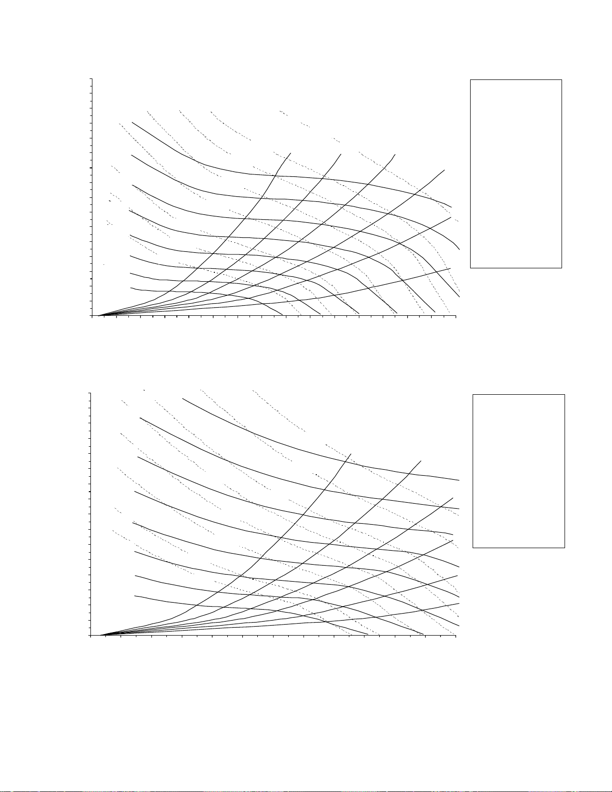
Figure 4-4 (Continued)
40, 50 & 55 Ton Supply Fan Performance with Inlet Guide Vanes
8.0
7.5
7.0
1200 RPM
6.5
6.0
1100 RPM
5.5
5.0
1000 RPM
4.5
4.0
900 RPM
3.5
3.0
800 RPM
2.5
STATIC PRESSURE, Inches w.c.
700 RPM
2.0
600 RPM
1.5
500 RPM
1.0
0.5
0.0
0 2000 4000 6000 8000 10000 12000 14000 16000 18000 20000 22000 24000 26000 28000 30000
10 HP
7.5 HP
5 HP
20 HP
15 HP
30 HP
25 HP
CFM
40 HP
40% wocfm
60, 70 & 75 Ton Supply Fan Performance with Inlet Guide Vanes
50%
60%
S_HFC40, C50, C55
Dual 20 X 20 Fans
Entrance Loss es
- with Inlet Guide Vanes
- without Evap Coil
- without Fil ters
- without Return A ir Dam pers
- without Ex haus t
Fan Curve Limits
70%
- Minimum Motor HP = 7.5
- Maximum Motor HP
C40, C50 & C55 = 30 HP
- Maximum RPM
7.5 - 15 HP = 1141
20 - 30 HP = 1170
80%
- Maximum CFM
C40 = 18,000
C50 = 22,500
C55 = 24,000
- Maximum Static Pressure
Leaving the Unit = 4.0" w.c .
90%
8.0
7.5
7.0
6.5
6.0
5.5
5.0
4.5
4.0
3.5
3.0
2.5
STATIC PRESSURE, Inches w.c.
2.0
1.5
1.0
0.5
0.0
1100 RPM
1000 RPM
900 RPM
800 RPM
700 RPM
600 RPM
500 RPM
0 3000 6000 9000 12000 15000 18000 21000 24000 27000 30000 33000 36000
1200 RPM
50 HP
40% wocfm
40 HP
25 HP
30 HP
20 HP
15 HP
10 HP
7.5 HP
CFM
50%
S_HF C60, C70, C75
Dual 22 X 22 Fans
Entrance Loss es
- with Inlet Guide Vanes
- without Evap Coil
- without Filters
- with out Return Air Dampers
- without Exhaust
Fan Curve Limit s
- Minimum Motor HP = 10
- Maximum Motor HP = 40
60%
- Maximum RPM = 1130
- Maximum CFM
C60 = 27,000
C70 & C75 = 30,000
- Maximum Static Pressure
70%
Leaving the Unit = 4. 0" w.c .
80%
90% woc fm
74
Page 77

Figure 4-4 (Continued)
90, 105, 115, & 130 Ton Supply Fan Performance with Inlet Guide Vanes
9
8
1
6
0
0
R
PM
7
1
5
0
0
R
P
M
6
1
4
0
0
R
PM
1
3
0
0
R
P
5
4
Static Presure, Inches w.c.
3
2
1
0
0 10000 20000 30000 40000 5 0000 60000
M
1
2
0
0
R
P
M
1
1
0
0
R
P
M
1
0
0
0
R
P
M
9
0
0
R
P
M
M
F
C
O
W
%
0
4
2
0
H
CFM
M
F
C
O
W
%
0
5
4
3
0
H
2
P
5
H
P
P
M
F
C
O
W
%
0
6
7
5
6
0
H
P
5
0
H
P
0
H
P
%
0
7
1
0
0
H
H
P
M
F
C
O
W
M
P
F
C
O
W
%
0
8
M
F
C
O
W
%
0
9
75
Page 78

Table 4-2
D
G
y
A
A
A
5
AN/A
AN/A
AN/A
AN/A
AN/A
AN/A
AN/A
AN/A
AN/A
G
y
20 through 75 Ton Component Static Pressure Drops (Inches W.C.)
CFM Perm Bag Cartridge Std With Or
Nom ST
Tons AIR Wet Dr
4,000 .07 .05 .14 .10 .02 N/A .02 .05 .06 .02 .06 .03 .03 .01 .3 .24 .01 .03
6,000 .13 .10 .27 .20 .05 .05 .04 .09 .12 .05 .12 .06 .06 .02 .5 .44 .02 .06
8,000 .21 .16 .43 .32 .09 .09 .07 .15 .19 .10 .20 .09 .09 .03 .71 .68 .05 .12
20
9,000 .26 .20 .52 .39 .12 .12 .09 .19 .24 .12 .22 .11 .11 .04 .83 .81 .07 .15
10,000 .31 .23 .61 .46 .14 .15 .11 .23 .28 .15 .29 .13 .13 .05 .95 .95 .10 .19
12,000 .41 .31 .82 .63 .20 .22 .17 .33 .40 .22 .42 .15 .15 .06 1.19 1.26 .14 .27
5,000 .10 .07 .20 .15 .03 N/A .03 .07 .09 .04 .09 .05 .05 .02 .40 .34 .01 .03
6,000 .13 .10 .27 .20 —— .05 —— —— —— ———— —— —— —— .50 .44 —— ——
7,500 .19 .15 .39 .29 .08 .08 .06 .14 .17 .09 .18 .09 .09 .03 .66 .62 .04 .10
10,000 .31 .23 .61 .46 .14 .15 .11 .23 .28 .15 .29 .13 .13 .05 .95 .95 .10 .19
25
11,000 .36 .27 .71 .54 .17 .18 .13 .29 .33 .19 .35 .15 .15 .06 1.06 1.11 .12 .23
12,500 .44 .34 .87 .67 .22 .23 .18 .33 .42 .24 .42 .19 .19 .08 1.29 1.34 .19 .30
14,000 .52 .40 1.05 .81 .28 .29 .21 .41 .53 .30 .53 .24 .24 .10 —— —— .24 .39
6,000 .15 .11 .20 .15 .05 .05 .04 .09 .12 .05 .12 .04 .04 .01 .34 .26 .02 .06
9,000 .29 .22 .39 .29 .11 .12 .09 .19 .24 .12 .22 .07 .17 .02 .54 .48 .07 .15
12,000 .46 .35 .61 .46 .20 .21 .16 .31 .39 .22 .41 .11 .11 .04 .75 .75 .16 .27
30
14,000 .59 .45 .78 .60 .26 .29 .22 .40 .51 .30 .50 .14 .14 .06 .95 .95 .25 .39
15,000 .65 .50 .87 .67 .30 .33 .25 .45 .57 .33 .52 .16 .16 .07 1.03 1.06 .30 .43
17,000 .80 .62 1.06 .82 .39 .42 .35 .58 .73 .42 .67 .21 .21 .09 1.20 1.30 .39 .59
8,000 .10 .07 .20 .15 .09 N/A .07 .09 .11 .05 .11 .04 .04 .02 .37 .31 .01 .03
10,000 .14 .11 .29 .21 —— .11 —— —— —— —— —— —— —— —— .49 .43 —— ——
12,000 .19 .14 .39 .29 .20 .15 .16 .17 .22 .11 .21 .08 .08 .03 .61 .56 .04 .07
16,000 .31 .23 .61 .46 .34 .26 .29 .28 .36 .20 .36 .12 .12 .05 .88 .87 .10 .09
40
17,000 .34 .26 .67 .51 N/
20,000 .44 .34 .87 .67 N/
22,000 .51 .39 1.02 .79 N/
10,000 .17 .13 .23 .17 .12 .10 .11 .13 .16 .07 .15 .04 .04 .01 .37 .30 .03 .05
14,000 .29 .22 .39 .29 .26 .20 .22 .22 .28 .15 .28 .07 .07 .03 .56 .50 .07 .08
17,000 .39 .30 .53 .40 .39 .29 .32 .31 .40 .22 .41 .10 .10 .04 .72 .68 .12 .11
50/5
20,000 .51 .39 .68 .52 .58 .41 .44 .42 .52 .30 .51 .12 .12 .05 .88 .88 .19 .17
24,000 .69 .53 .91 .70 .73 .58 .62 .48 .72 .45 .75 .16 .16 .07 1.11 1.17 .30 .23
28,000 .88 .68 1.17 .91 .99 .79 .84 .62 .98 .61 .99 .20 .20 .10 —— —— .39 .30
12,000 .13 .10 .25 .18 .10 .08 .16 .10 .13 .06 .11 .05 .05 .01 .44 .37 .02 .07
16,000 .20 .16 .39 .29 .18 .14 .29 .17 .21 .11 .19 .07 .07 .02 .63 .58 .05 .10
20,000 .29 .23 .55 .42 .27 .21 .44 .24 .31 .16 .27 .10 .10 .03 .84 .82 .10 .16
60
24,000 .39 .31 .74 .57 .40 .30 .62 .33 .42 .22 .39 .11 .11 .04 1.06 1.08 .16 .23
28,000 .50 .39 .95 .73 .48 .33 .85 .44 .55 .32 .50 .17 .17 .06 —— —— .30 .30
30,000 .56 .44 1.06 .82 .62 .38 .98 .51 .63 .37 .57 .20 .20 .07 —— —— .34 .34
12,000 .20 .16 N/
16,000 .32 .26 N/
20,000 .46 .37 N/
22,000 .54 .43 N/
24,000 .62 .50 N/
70
26,000 .70 .56 N/
28,000 .79 .64 N/
31,000 .93 .75 N/
33,000 1.03 .83 N/
12,000 .25 .18 .31 .23 .10 .08 .16 .10 .13 .06 .11 .05 .05 .01 .44 .37 .02 .07
16,000 .39 .29 .49 .37 .18 .14 .29 .17 .21 .11 .19 .07 .07 .02 .63 .58 .05 .10
20,000 .55 .42 .69 .53 .27 .21 .44 .24 .31 .16 .27 .10 .10 .03 .84 .82 .10 .16
22,000 .65 .49 .81 .62 .33 .25 .53 .29 .37 .19 .33 .12 .12 .04 .95 .95 .13 .20
24,000 .74 .57 .93 .71 .40 .30 .62 .33 .42 .22 .39 .14 .14 .04 1.06 1.08 .16 .23
75
26,000 .84 .65 1.05 .81 .47 .32 .73 .39 .49 .27 .45 .16 .16 .05 1.17 1.23 .23 .26
28,000 .95 .73 1.19 .92 .54 .33 .85 .44 .55 .32 .50 .17 .17 .06 1.22 1.29 .30 .30
31,000 1.12 .87 1.40 1.08 .60 .40 1.04 .49 .61 .39 .55 .21 .21 .07 —— —— .37 .36
33,000 1.24 .96 1.55 1.20 .65 .46 1.18 .52 .67 .44 .60 .24 .24 .08 —— —— .42 .40
Evaporator Coil
Std. Capacity
High
Wet DryLow High A ll KW's Low High Low High Fiber Effic. Mesh Prefilter Prefilter Curb Exh. Fan
SFHF/G
.10 .08 .16 .10 .13 .06 .11 .05 .05 .01 .44 .37 .02 .07
.18 .14 .29 .17 .21 .11 .19 .07 .07 .02 .63 .58 .05 .10
.27 .21 .44 .24 .31 .16 .27 .10 .10 .03 .84 .82 .10 .16
.33 .25 .53 .29 .37 .19 .33 .12 .12 .04 .95 .95 .13 .20
.40 .30 .62 .33 .42 .22 .39 .14 .14 .04 1.06 1.08 .16 .23
.47 .32 .73 .39 .49 .27 .45 .16 .16 .05 1.17 1.23 .23 .26
.54 .33 .85 .44 .55 .32 .50 .17 .17 .06 1.22 1.29 .30 .30
.60 .40 1.04 .49 .61 .39 .55 .21 .21 .07 —— —— .37 .36
.65 .46 1.18 .52 .67 .44 .60 .24 .24 .08 —— —— .42 .40
SEHF/
.29 .32 .31 .39 .22 .41 .13 .13 .06 .95 .95 .12 .11
.41 .44 .42 .52 .30 .51 .17 .17 .08 1.17 1.22 .19 .17
.50 .53 .51 .63 .36 .62 .21 .21 .10 —— —— .23 .20
SLHF/
SSHF/G
Throwawa
Std. High Wire And And Roof Without
FiltersHeat ing S ystem
Econ.
76
Page 79

Table 4-2 (Continued)
D
R
y
D
R
D
R
90 through 130 Ton Component Static Pressure Drops (Inches W.C.)
CFM Perm Bag Cartridge Std With Or
Nom ST
Tons AI
27,000 .40 .31 .67 .51 N/A .25 .13 .26 .31 .22 .32 .11 .13 N/A .68 .65 —— .20
32,000 .53 .41 .89 .68 N/A .31 .16 .35 .41 .30 .43 .14 .16 N/A .84 .84 .31
37,000 .67 .52 1.12 .86 N/A .39 .23 .45 .52 .40 .55 .17 .19 N /A 1.02 1.04 .41
90
42,000 .82 .63 1.36 1.06 N/A .46 .29 .56 .65 .50 .68 .21 .22 N/A 1.19 1.06 .52
45,000 .92 .71 1.53 1.19 N/A .52 .32 .63 .73 .58 .76 .24 .24 N/A —— —— .63
31,000 .56 .45 .84 .64 N/A .28 .17 .33 .39 .29 .40 N/A .13 N/A .82 .80 —— .22
35,000 .68 .54 1.02 .78 N/A .36 .21 .41 .48 .36 .50 N/A .16 N/A .96 .96 .32
39,000 .81 .65 1.21 .94 N/A .42 .26 .49 .57 .44 .60 N/A .19 N/A 1.09 1.12 .44
105
43,000 .94 .76 1.42 1.10 N/A .45 .30 .57 .66 .53 .71 N/A .22 N/A 1.22 1.30 .54
46,000 1.05 .84 1.58 1.23 N /A .55 .34 .65 .75 .61 .79 N/A .24 N/A —— —— .64
31,000 .84 .64 N/A N/A N/A .28 .17 .33 .39 .29 .40 N/A .13 N/A .82 .80 —— .22
35,000 1.03 .79 N/A N/A N/A .36 .21 .41 .48 .36 .50 N/A .16 N/A .96 .96 .32
115/
39,000 1.21 .94 N/A N/A N/A .42 .26 .49 .57 .44 .60 N/A .19 N/A 1.09 1.12 .44
130
43,000 1.421.10 N/A N/A N/A .45 .30 .57 .66 .53 .71 N/A .22 N/A 1.22 1.30 .54
46,000 1.581.23 N/A N/A N/A .55 .34 .65 .75 .61 .79 N/A .24 N/A 0 0 .64
Notes:
1. Stat ic pressure drops of accessory c omponents must be added to external static pressure to ent er f an select ion t ables.
2. G as heat section maximum temperatur e r ise of 60 F .
3. T hr owaway filter option limited to 300 ft/min face velocity.
4. Bag filt er opt ion limited t o 740 ft/min face velocity.
5. Horizontal roof c urbs assume 0.50" static pressure drop or double the standar d roof cur b pressure drop, whichever is greater.
6. No addit ional pressure loss for model SX HF.
7. 90 - 130 t on r oof cur bs adds no pressure drop.
Evaporator Coil
Std. Capacity
Wet Dry Wet Dry Low High All K W's Low High Low High F iber Effic. Mesh Prefilter Prefilter Curb Exh. Fan
High
SFHF/G
SEHF/G Std. H igh Wire And And Roof Without
SLHF/G SSHF/G
Throwawa
FiltersHeat in g System
Econ.
Table 4-3
90 through 130 Ton 100% Modulating Exhaust Fan Performance
ST
AI
0.25" W.G. 0.50" W.G. 0.75" W.G. 1.00" W.G. 1.25" W.G. 1.50" W.G
CFM RPM BHP RPM BHP RPM BHP RPM BHP RPM BHP RPM BHP
24,000
27,000
30,000
33,000
36,000
40,000
ST
AI
477 7.04 513 7.95 561 9.29 604 10.66 648 12.15 693 13.83
530 9.80 558 10.69 597 11.99 639 13.54 677 15.08 716 16.73
584 13.24 608 14.16 637 15.34 675 16.96 712 18.67 746 20.38
638 17.42 659 18.39 683 19.53 713 21.02 749 22.88 781 24.75
693 22.42 711 23.46 732 24.61 756 25.99 786 27.75 818 29.80
766 30.50 782 31.62 800 32.83 819 34.17 841 35.75 868 37.69
Negative Static Pressure
1.75" W.G. 2.00" W.G. 2.25" W.G. 2.50" W.G.
CFM RPM BHP RPM BHP RPM BHP RPM BHP
24,000
27,000
30,000
33,000
36,000
40,000
Note:
Blocked areas identify non-standard drive selections.
737 15.66 781 17.54 823 19.45 862 21.42
756 18.53 796 20.51 835 22.59 874 24.71
781 22.18 817 24.10 853 26.19 889 28.42
812 26.63 844 28.57 877 30.61 910 32.79
848 31.85 877 33.89 905 35.98 935 38.14
897 39.94 926 42.24 952 44.50 977 46.77
Negative Static Pressure
77
Page 80
Table 4-3 (Continued)
y
20 through 75 Ton 100% Modulating Exhaust Fan Performance
Negative Static Pressure
Cfm 0.25" W.G. 0.50" W.G. 0.75" W.G. 1.00" W.G. 1.25" W.G. 1.50" W.G. 1.75" W.G. 2.00" W.G.
Std.
Air RPM BHP RPM BHP RPM BHP RPM BHP RPM BHP RPM BHP RPM BHP RPM BHP
S*HF-C20 4,000
6,000
8,000
10,000
S*HF-C25 4,000
6,000
8,000
10,000
12,000
S*HF-C30 4,000
6,000
8,000
10,000
12,000
14,000
S*HF-C40 7,500
9,000
12,000
14,000
16,000
S*HF-C50 9,000
12,000
15,000
18,000
20,000
S*HF-C55 10,000
13,000
16,000
19,000
21,500
S*HF-C60 12,000
C70 & -C 75 15,000
18,000
21,000
24,000
Note:
Blocked areas of tabl e ide nti f
399 0.38 538 0.75 640 1.08 730 1.45 811 1.87 882 2.34 947 2.88
453 0.74 570 1.17 675 1.65 765 2.22 845 2.78
547 1.59 619 1.81 711 2.48 797 3.01
640 2.79
399 0.38 538 0.75 640 1.08 730 1.45 811 1.87 882 2.34 947 2.88 1017 3.55
453 0.74 570 1.17 675 1.65 765 2.22 845 2.78 912 3.27 975 3.77 1036 4.30
547 1.59 619 1.81 711 2.48 797 3.01 876 3.66 947 4.40
640 2.79 712 3.25 767 3.48 837 4.26 911 5.04
737 4.44
399 0.38 538 0.75 640 1.08 730 1.45 811 1.87 882 2.34 947 2.88 1017 3.55
453 0.74 570 1.17 675 1.65 765 2.22 845 2.78 912 3.27 975 3.77 1036 4.30
547 1.59 619 1.81 711 2.48 797 3.01 876 3.66 947 4.40 1013 5.18 1075 5.94
640 2.79 712 3.25 767 3.48 837 4.26 911 5.04 980 5.70 1045 6.46 1106 7.31
737 4.44 806 5.22 860 5.64 905 5.89 956 6.49
837 6.67
334 0.75 438 1.21 535 1.77 616 2.35 686 2.98 750 3.64 809 4.34 864 5.06
362 1.09 449 1.57 536 2.16 618 2.84 689 3.52 753 4.24 812 4.99 867 5.77
435 2.19 496 2.70 563 3.35 628 4.04 693 4.83 757 5.71 817 6.63 873 8.53
486 3.22 542 3.86 594 4.47 653 5.25 707 6.04 763 6.91 819 7.86 874 8.89
537 4.55 592 5.35 636 6.00 683 6.74 735 7.64 783 8.53 831 9.47 880 10.48
362 1.09 449 1.57 536 2.16 618 2.84 689 3.52 753 4.24 812 4.99 867 5.77
435 2.19 496 2.70 563 3.35 628 4.04 693 4.83 757 5.71 817 6.63 873 7.53
511 3.85 567 4.56 614 5.18 667 5.96 720 6.80 771 7.66 824 8.60 876 9.63
590 6.21 642 7.16 685 7.97 724 8.69 766 9.54 812 10.54 856 11.55 898 12.56
644 8.26 692 9.35 735 10.33 772 11.17 807 11.97 844 12.91 885 14.00 926 15.13
386 1.40 463 1.90 540 2.48 618 3.18 691 3.94 755 4.70 814 5.48 869 6.30
461 2.67 518 3.23 578 3.88 639 4.61 698 5.39 759 6.26 818 8.22 874 8.21
537 4.55 592 5.35 636 6.00 683 6.74 735 7.64 783 8.53 831 9.47 880 10.48
617 7.19 667 8.21 710 9.10 747 9.87 785 10.68 827 11.66 870 12.73 911 13.80
685 10.08 731 11.26 772 12.36 809 13.33 842 14.20 874 15.08 910 16.10 948 17.28
351 1.49 423 2.09 502 3.00 572 4.02 634 5.07 690 6.09 740 7.04 784 7.91
412 2.68 460 3.15 521 3.96 585 5.02 646 6.24 702 7.53 754 8.83 801 10.14
478 4.41 516 4.88 557 5.54 607 6.49 662 7.66 715 9.01 766 10.48 814 12.01
547 6.75 578 7.36 612 7.92 647 8.71 688 9.77 735 11.03 781 12.46 827 14.03
617 9.83 644 10.59 672 11.22 702 11.88 732 12.77 766 13.89 805 15.22
nonstandard drive selections.
78
Page 81

Table 4-4
y
y
20 through 75 Ton 50% Modulating Exhaust Fan Performance
Negative Static Pressure
Cfm 0.20" W.G . 0.40" W.G. 0.60" W.G. 0.80" W.G. 1.00" W.G. 1.20" W.G. 1.40" W.G.
Std.
Air RPM BHP RPM BHP RPM BHP RPM BHP RPM BHP RPM BHP RPM BHP
S*HF-C20 2,000
S*HF-C25 3,000
4,000
5,000
6,000
S*HF-C30 2,000
3,000
4,000
5,000
6,000
7,000
S*HF-C40 3,000
5,000
7,000
9,000
11,000
S*HF-C50 3,000
S*HF-C55 5,000
7,000
9,000
11,000
S*HF-C60 4,000
S*HF-C70 6,000
S*HF-C75 8,000
10,000
12,000
13,000
Note:
Blocked areas iden tif
364 0.17 487 0.30 582 0.45 658 0.58 731 0.73 797 0.90 856 1.08
435 0.36 522 0.51 614 0.67 694 0.88 765 1.11 830 1.34 886 1.54
529 0.76 592 0.86 654 1.03 728 1.29 797 1.51 861 1.77 919 2.05
623 1.32 687 1.56 735 1.67 778 1.79 836 2.13 896 2.45 953 2.72
722 2.13 779 2.47 830 2.72 890 2.86 905 2.96
364 0.17 487 0.30 582 0.45 658 0.58 731 0.73 797 0.90 856 1.08
435 0.36 522 0.51 614 0.67 694 0.88 765 1.11 830 1.34 886 1.54
529 0.76 592 0.86 654 1.03 728 1.29 797 1.51 861 1.77 919 2.05
623 1.32 687 1.56 735 1.67 778 1.79 836 2.13 896 2.45 953 2.72
722 2.13 779 2.47 830 2.72 870 2.86 905 2.96 944 3.16 994 3.59
824 3.23 874 3.64 922 4.02 965 4.30 1000 4.48 1032 4.59 1062 4.72
288 0.22 393 0.38 477 0.55 547 0.74 611 0.94 668 1.16 721 1.39
372 0.66 430 0.83 495 1.05 557 1.29 621 1.57 680 1.87 732 2.16
472 1.55 522 1.82 563 2.04 606 2.29 653 2.59 698 2.91 742 3.24
578 3.06 621 3.41 661 3.76 695 4.06 725 4.34 758 4.65 794 5.01
688 5.36 725 5.80 760 6.24 793 6.66 823 7.06 850 7.42 875 7.76
271 0.29 364 0.54 438 0.82 499 1.07 550 1.30 601 1.56 651 1.87
339 0.71 391 0.90 456 1.22 517 1.60 572 2.01 622 2.43 668 2.85
425 1.55 460 1.73 497 1.96 542 2.30 591 2.72 639 3.20 684 3.73
517 2.88 543 3.13 571 3.34 600 3.59 632 3.94 668 4.37 707 4.87
612 4.84 633 5.15 655 5.43 678 5.68 702 5.95 726 6.29 752 6.91
659 6.09 679 6.44 699 6.76 720 7.04 741 7.31
non-standard motor selections.
90 through 130 Ton 50% Modulating Exhaust Fan Performance
CFM Negative Static Pressure
STD 0.250" W.G. 0.500" W.G. 0.750" W.G. 1.000" W.G. 1.250" W.G. 1.500" W.G.
AIR RPM BHP RPM BHP RPM BHP RPM BHP RPM BHP RPM BHP
12,000
14,000
16,000
18,000
20,000
CFM Negative Static Pressure
STD 1.750" W.G. 2.000" W.G. 2.250" W.G. 2.500" W.G.
AIR RPM BHP RPM BHP RPM BHP RPM BHP
12,000
14,000
16,000
18,000
20,000
Note:
Blocked areas identif
452 3.68 495 4.21 536 4.85 576 5.46 614 6.17 651 6.95
516 5.71 551 6.21 586 6.85 622 7.63 657 8.36 690 9.09
583 8.41 609 8.85 643 9.57 672 10.29 704 11.18 735 12.07
650 11.88 672 12.29 699 12.94 729 13.79 755 14.59 782 15.56
718 16.20 737 16.62 758 17.18 785 18.03 811 18.97 835 19.86
687 7.73 722 8.55 759 9.46 797 10.45
723 9.96 754 10.88 785 11.79 815 12.72
764 12.84 793 13.72 822 14.72 850 15.76
811 16.62 838 17.53 864 18.41 889 19.39
859 20.87 885 22.05 910 23.18 934 24.17
non-standard motor selections.
79
Page 82

Unit Start-Up (Continued)
Economizer Damper Adjustment
Exhaust Air Dampers
Verify that the exhaust dampers (if equipped) close tightly
when the unit is off. Adjust the damper linkage as necessary
to ensure proper closure. An access panel is provided under each damper assembly.
Fresh Air & Return Air Damper Operation
The fresh air and return air damper linkage is accessible
from the filter section of the unit. The damper linkage connecting the fresh air dampers to the return air dampers is
preset from the factory in the number 1 position. Refer to
Table 4-5 for the appropriate linkage position for the unit
and operating airflow (CFM).
WARNING
No Step Surface!
Do not walk on the sheet metal drain pan. Walking on
the drain pan could cause the supporting metal to collapse. Failure of the drain pan could result in death or
serious injury.
Note: Bridging between the unit's main supports
may consist of multiple 2 by 12 boards or sheet
metal grating.
Arbitrarily adjusting the fresh air dampers to open fully
when the return air dampers are closed or; failing to maintain the return air pressure drop with the fresh air dampers
when the return air dampers are closed, can overload the
supply fan motor and cause building pressurization control
problems due to improper CFM being delivered to the
space.
The fresh air/return air damper linkage is connected to a
crank arm with a series of holes that allows the installer or
operator to modify the amount of fresh air damper travel in
order to match the return static pressure. Refer to
Table 4-5 for the equivalent return air duct losses that correspond to each of the holes illustrated in Figure 4-5.
To Adjust the Fresh Air Damper Travel:
1. Drill a 1/4" hole through the unit casing up stream of the
return air dampers. Use a location that will produce an
accurate reading with the least amount of turbulence.
Several locations may be necessary, and average the
reading.
2. Close the disconnect switch or circuit protector switch
that provides the supply power to the unit's terminal
block 1TB1 or the unit mounted disconnect switch 1S14.
3. Turn the 115 volt control circuit switch 1S1 and the 24
volt control circuit switch 1S70 to the "On" position.
4. Open the Human Interface access door, located in the unit
control panel, and press the SERVICE MODE key to
display the first service screen. Refer to the latest edition
of the applicable SAHF-PTG manual for CV or VAV
applications for the SERVICE TEST screens and
programming instructions.
5. Use Table 4-1 to program the following system
components for operation by scrolling through the
displays;
Supply Fan (On)
Inlet Guide Vanes (100% Open, if applicable)
Variable Frequency Drive (100% Output, if applicable)
RTM Occ/Unocc Output (Unoccupied)
Fresh Air Dampers (Closed)
6. Once the configuration for the components is complete,
press the NEXT key until the LCD displays the “Start test
in __Sec.” screen. Press the + key to designate the delay
before the test is to start. This service test will begin after
the TEST START key is pressed and the delay designated in this step has elapsed. Press the ENTER key to
confirm this choice.
WARNING
Rotating Components!
Disconnect all electric power, including remote disconnects before servicing. Follow proper lockout/tagout
procedures to ensure the power can not be inadvertently energized. Failure to disconnect power before servicing could result in death or serious injury.
7. Press the TEST START key to start the test. Remember
that the delay designated in step 6 must elapse before
the fan will begin to operate.
8. With the fresh air dampers fully closed and the supply fan
operating at 100% airflow requirements, measure the
return static pressure at the location determined in
step 1.
9. Press the STOP key at the Human Interface Module in
the unit control panel to stop the fan operation.
WARNING
Hazardous V oltage!
Disconnect all electric power, including remote disconnects before servicing. Follow proper lockout/tagout
procedures to ensure the power can not be inadvertently energized. Failure to disconnect power before servicing could result in death or serious injury.
HIGH VOLTAGE IS PRESENT AT TERMINAL BLOCK
1TB1 OR UNIT DISCONNECT SWITCH 1S14.
10. Open the field supplied main power disconnect switch
upstream of the rooftop unit. Lock the disconnect switch
in the "Open" position while working on the dampers.
11. Compare the static pressure reading to the static pressure ranges and linkage positions in Table 4-5 for the
unit size and operating CFM.
80
Page 83

Unit Start-Up (Continued)
y
To relocate the fresh air/return air connecting rod to balance
the fresh air damper pressure drop against the return static
pressure, use the following steps. If no adjustment is necessary, proceed to step 17.
12. Remove the drive rod and swivel from the crank arm(s).
If only one hole requires changing, loosen only that end.
13. Manually open the return air dampers to the full open
position.
14. Manually close the fresh air dampers.
15. Reattach the drive rod and swivel to the appropriate
hole(s). The length of the drive rod may need to be
adjusted to align with the new hole(s) location. If so,
loosen the lock nut on the drive rod against the swivel.
Turn the swivel "in" or "out" to shorten or lengthen the rod
as necessary. For some holes, both ends of the rod may
need to be adjusted.
16. Tighten the lock nut against the swivel(s).
17. Plug the holes after the proper CFM has been
established.
Table 4-5
F/A Damper Travel Adjustment
Position of Damper
Connecting Rod Crank Arm Hole
(See Figure 4-5) Configuration
Position #1 2 - 3 Use the tables below to select the appropriate
Position #2 2 - 4 crank arm hole configuration based on the;
Position #3 2 - 5 a. specific unit,
Position #4 2 - 6 b. operating CFM,
Position #5 1 - 8 c. and return static pressure.
Position #6 1 - 7
Note:
As shipped from the factor
installed in Position #1.
, the connect rod is
Fresh Air Damper Pressure Drop (
20 and 25 Ton Units 50 - 55 Ton U nits
Damper Position Damper Position
CFM #1 #2 #3 #4 #5 #6 CFM #1 #2 #3 #4 #5 #6
4000 0.03 0.04 0.06 0.13 0.16 0.33 10000 0.03 0.04 0.09 0.18 0.23 0.55
6000 0.03 0.04 0.10 0.20 0.30 0.90 14000 0.09 0.12 0.20 0.35 0.50 1.36
8000 0.19 0.21 0.32 0.52 0.75 1.75 18000 0.31 0.36 0.50 0.79 1.10 -
9000 0.30 0.35 0.48 0.76 1.08 2.40 20000 0.45 0.51 0.70 1.05 1.57 10000 0.45 0.51 0.70 1.05 1.57 - 22000 0.58 0.66 0.75 1.30 1.95 11000 0.62 0.71 0.95 1.42 2.15 - 24000 0.75 0.88 1.10 1.75 2.50 -
30 Ton Units 60 - 75 Ton U nits
Damper Position Damper Position
CFM #1 #2 #3 #4 #5 #6 CFM #1 #2 #3 #4 #5 #6
6000 0.03 0.04 0.07 0.15 0.20 0.43 14000 0.03 0.04 0.12 0.25 0.35 1.05
8000 0.03 0.05 0.11 0.21 0.30 0.90 18000 0.19 0.21 0.32 0.52 0.75 1.75
10000 0.15 0.19 0.26 0.43 0.62 1.50 22000 0.45 0.51 0.70 1.05 1.57 11000 0.20 0.25 0.37 0.60 0.85 1.85 26000 0.70 0.80 1.02 1.58 2.30 12000 0.31 0.36 0.50 0.79 1.10 2.40 28000 0.88 1.03 1.30 2.20 - 13000 0.42 0.48 0.62 0.97 1.42 - 30000 1.05 1.22 1.55 2.65 - -
40 Ton Units 90 - 130 Ton Units
Damper Position Damper Position
CFM #1 #2 #3 #4 #5 #6 CFM #1 #2 #3 #4 #5 #6
8000 0.03 0.04 0.08 0.16 0.21 0.52 27000 0.31 0.36 0.50 0.79 1.10 2.40
10000 0.03 0.05 0.11 0.21 0.30 0.90 32000 0.55 0.64 0.72 1.25 1.88 12000 0.10 0.13 0.21 0.38 0.55 1.40 36000 0.75 0.88 1.10 1.75 2.50 14000 0.20 0.25 0.37 0.60 0.85 1.85 40000 1.00 1.18 1.50 2.50 - 16000 0.41 0.46 0.60 0.94 1.38 - 43000 1.20 1.42 1.92 - - 18000 0.56 0.65 0.74 1.28 1.92 - 46000 1.40 1.58 2.29 - - -
inches w.c.
)
81
Page 84

Unit Start-Up (Continued)
Figure 4-5
Fresh Air & Return Air Linkage Adjustment
Top View
RETURN AIR
DAMPERS
2
FILTER
SECTION
1
3
4
5
6
FRESH AIR
DAMPERS
7
4. Tur n the 115 volt control circuit switch 1S1 and the 24
volt control circuit switch 1S70 to the "On" position.
5. Open the Human Interface access door, located in the
unit control panel, and press the SERVICE MODE key to
display the first service screen. Refer to the latest edition
of the RT-SVP01A-EN for CV applications or
RT-SVP02A-EN for VAV applications for the SERVICE
TEST screens and programming instructions.
6. Use Table 4-1 to program the following system components for operation by scrolling through the displays;
20 to 30 Ton
Compressor 1A (On)
Compressor 1B (Off)
8
Condenser Fans
40 through 60 Ton
Compressor 1A (On)
Compressor 1B (Off)
Compressor 2A (Off)
Compressor 2B (Off)
Condenser Fans
70 & 105 Ton
Compressor 1A & 1B (On)
Compressor 1C (Off)
Compressor 2A & 2B (Off)
Compressor 2C (Off)
Condenser Fans
115 & 130 Ton
Compressor 1A & 1B (On)
Compressor 1C & 1D (Off)
Compressor 2A & 2B (Off)
Compressor 2C & 2D (Off)
Condenser Fans
Compressor Start-Up
(All Systems)
1. Ensure that the "System" selection switch at the remote
panel is in the "Off" position.
2. Before closing the disconnect switch, ensure that the
compressor discharge service valve and the liquid line
service valve for each circuit is back seated.
CAUTION
Compressor Damage!
Do not allow liquid refrigerant to enter the suction line.
Excessive liquid accumulation in the liquid lines may
result in compressor damage.
COMPRESSOR SERVICE VALVES MUST BE FULLY
OPENED BEFORE START-UP (SUCTION, DISCHARGE,
LIQUID LINE, AND OIL LINE).
3. Close the disconnect switch or circuit protector switch
that provides the supply power to the unit's terminal block
1TB1 or the unit mounted disconnect switch 1S14 to allow
the crankcase heater to operate a minimum of 8 hours before continuing.
Note: Compressor Damage could occur if the
crankcase heater is not allowed to operate the
minimum of 8 hours before starting the
compressor(s).
7. Attach a set of service gauges onto the suction and discharge gauge ports for each circuit. Refer to Figure 4-6
for the various compressor locations.
8. Once the configuration for the components is complete,
press the NEXT key until the LCD displays the “Start test
in __Sec.” screen. Press the + key to designate the delay
before the test is to start. This service test will begin after
the TEST START key is pressed and the delay designated in this step has elapsed. Press the ENTER key to
confirm this choice.
WARNING
Rotating Components!
Disconnect all electric power, including remote disconnects before servicing. Follow proper lockout/tagout
procedures to ensure the power can not be inadvertently energized. Failure to disconnect power before servicing could result in death or serious injury.
9. Press the TEST START key to start the test. Remember
that the delay designated in step 8 must elapse before
the system will begin to operate.
10. Once each compressor or compressor pair has started,
verify that the rotation is correct. If a scroll compressor is
rotating backwards, it will not pump and a loud rattling
sound can be observed. Check the electrical phasing at
the load side of the compressor contactor. If the phasing
is correct, before condemning the compressor, inter-
82
Page 85

Unit Start-Up (Continued)
change any two leads to check the internal motor phasing. If the compressor runs backward for an extended
period (15 to 30 minutes), the motor winding can over
heat and cause the motor winding thermostats to open.
This will cause a “compressor trip” diagnostic and stop
the compressor.
11. Press the STOP key at the Human Interface Module in
the unit control panel to stop the compressor operation.
12. Repeat steps 5 through 11 for each compressor stage
and the appropriate condenser fans.
Refrigerant Charging
1. Attach a set of service gauges onto the suction and discharge gauge ports for each circuit. Refer to Figure 4-6
for the various compressor locations.
2. Open the Human Interface access door, located in the
unit control panel, and press the SERVICE MODE key to
display the first service screen. Refer to the latest edition
of the SAHF-PTG-1B for CV applications or SAHF-PTG2B for VAV applications for the SERVICE TEST screens
and programming instructions.
3. Use Table 4-1 to program the following system components for the number 1 refrigeration circuit by scrolling
through the displays;
Supply Fan (On)
Inlet Guide Vanes/VFD (100%, if applicable)
OCC/UNOCC Relay (Unoccupied for VAV units)
All Compressors for each circuit (On)
Condenser Fans for each circuit (On)
4. Once the configuration for the components is complete,
press the NEXT key until the LCD displays the “Start test
in __Sec.” screen. Press the + key to designate the delay
before the test is to start. This service test will begin after
the TEST START key is pressed and the delay designated in this step has elapsed. Press the ENTER key to
confirm this choice.
Note: Do Not release refrigerant to the atmosphere!
If adding or removing refrigerant is required, the
service technician must comply with all Federal,
State and local laws. Refer to general service
bulletin MSCU-SB-1 (latest edition).
7. Verify that the oil level in each compressor is correct. The
oil level may be down to the bottom of the sightglass but
should never be above the sightglass.
8. Press the STOP key at the Human Interface Module in
the unit control panel to stop the system operation.
9. Repeat steps 1 through 8 for the number 2 refrigeration
circuit.
10. After shutting the system off, check the compressor's
oil’s appearance. Discoloration of the oil indicates that an
abnormal condition has occurred. If the oil is dark and
smells burnt, it has overheated because of: compressor
is operating at extremely high condensing temperatures;
high superheat; a compressor mechanical failure; or, occurrence of a motor burnout.
If the oil is black and contains metal flakes, a mechanical
failure has occurred. This symptom is often accompanied
by a high compressor amperage draw.
If a motor burnout is suspected, use an acid test kit to
check the condition of the oil. Test results will indicate an
acid level exceeding 0.05 mg KOH/g if a burnout occurred.
The scroll compressor uses Trane OIL-42 without substitution. The appropriate oil charge for a 9 and 10 Ton
scroll compressor is 8.5 pints. For a 14 and 15 Ton scroll
compressor, use 13.8 pints.
Compressor Crankcase Heaters
9 and 10 ton scroll compressors have a 100-watt heater installed. 14 and 15 ton scroll compressors have two 80-watt
heaters installed per compressor.
WARNING
Rotating Components!
Disconnect all electric power, including remote disconnects before servicing. Follow proper lockout/tagout
procedures to ensure the power can not be inadvertently energized. Failure to disconnect power before servicing could result in death or serious injury.
5. Press the TEST START key to start the test. Remember
that the delay designated in step 4 must elapse before
the system will begin to operate.
6. After all of the compressors and condenser fans for the
number 1 circuit have been operating for approximately
30 minutes, observe the operating pressures. Use the
appropriate pressure curve in Tables 4-6 to determine
the proper operating pressures. For superheat and subcooling guidelines, refer to "Thermostatic Expansion
Valves and Charging by Subcooling" at the end of this
section.
Compressor Operational Sounds
Because of the scroll compressor design, it emits a higher
frequency tone (sound) than a reciprocating compressor. It
is designed to accommodate liquids, both oil and refrigerant, without causing compressor damage. The following discussion describes some of the operational sounds that differentiate it from those typically associated with a reciprocating compressor. These sounds do not affect the operation or reliability of the compressor.
At Shutdown
When a Scroll compressor shuts down, the gas within the
scroll expands and causes momentary reverse rotation until
the discharge check valve closes. This results in a “flutter”
type sound.
At Low Ambient Start-Up
When the compressor starts up under low ambient conditions, the initial flow rate of the compressor is low due to the
low condensing pressure. This causes a low differential
across the thermal expansion valve that limits its capacity.
Under these conditions, it is not unusual to hear the compressor rattle until the suction pressure climbs and the flow
rate increases.
83
Page 86

Figure 4-6
Compressor Locations
84
Page 87

Table 4-6
20 Ton Operating Pressure Curve (All Compressors and Condenser Fans "On")
COOLING CYCLE P RES SURE CURVE
(Based on Indoor Airflow of 400 CFM / Ton)
FULL LOAD
360
340
320
300
280
260
240
220
DISCHARGE PRESSURE, PSIG
200
180
160
50 55 60 65 70 75 80 85 90 95 100
To Check Operating Pressures
1. S t art the uni t and all ow t he pres sures t o st abiliz e.
2. Measure t he out door ai r dry bul b temperat ure (F)
entering the condenser c oi l .
3. Measure t he disc harge and suc t i on press ure (ps i g)
next to the compressor.
SUCT ION P RES SURE, PS IG
4. P l ot the outdoor dry bulb t em perature and the
operating suc t i on press ure (ps i g) ont o the c hart .
5. A t the point of inters ec tion, read to the l eft for the
discharge pres sure. The meas ured di s charge
press ure should be within ± 7 ps ig of t he graph.
105 F OD Am bi ent
95 F OD Am bi ent
85 F OD Am bi ent
75 F OD Am bi ent
65 F OD Am bi ent
25 Ton Operating Pressure Curve (All Compressors and Condenser Fans "On")
COOLING CYCLE P RES SURE CURVE
(Based on Indoor Airflow of 400 CFM / Ton)
FULL LOAD
380
360
340
320
300
280
260
240
DISCHARGE PRESSURE, PSIG
220
200
180
50 55 60 65 70 75 80 85 90 95 100
To Check Operating Pressures
1. S t art the uni t and all ow t he pres sures t o st abiliz e.
2. Measure t he out door ai r dry bul b temperat ure (F)
entering the condenser c oi l .
3. Measure t he disc harge and suc t i on press ure (ps i g)
next to the compressor.
SUCT ION P RES SURE, PS IG
105 F OD Am bi ent
95 F OD Am bi ent
85 F OD Am bi ent
75 F OD Am bi ent
65 F OD Am bi ent
4. P l ot the outdoor dry bulb t em perature and the
operating suc t i on press ure (ps i g) ont o the c hart .
5. A t the point of inters ec tion, read to the l eft for the
discharge pres sure. The meas ured di s charge
press ure should be within ± 7 ps ig of t he graph.
85
Page 88

Table 4-6 (Continued)
30 Ton Operating Pressure Curve (All Compressors and Condenser Fans "On")
COOLING CYCLE P RES SURE CURVE
(Based on Indoor Airflow of 400 CFM / Ton)
FULL LOAD
380
360
340
320
300
280
260
240
DISCHARGE PRESSURE, PSIG
220
200
180
50 55 60 65 70 75 80 85 90 95 100
To Check Operating Pressures
1. S t art the uni t and all ow t he pres sures t o st abiliz e.
2. Measure t he out door ai r dry bul b temperat ure (F)
entering the condenser c oi l .
3. Measure t he disc harge and suc t i on press ure (ps i g)
next to the compressor.
SUCT ION P RES SURE, PS IG
4. P l ot the outdoor dry bulb t em perature and the
operating suc t i on press ure (ps i g) ont o the c hart .
5. A t the point of inters ec tion, read to the l eft for the
discharge pres sure. The meas ured di s charge
press ure should be within ± 7 ps ig of t he graph.
105 F OD Am bi ent
95 F OD Am bi ent
85 F OD Am bi ent
75 F OD Am bi ent
65 F OD Am bi ent
40 Ton Operating Pressure Curve (All Compressors and Condenser Fans, per ckt, "On")
COOLING CYCLE P RES SURE CURVE
(Based on Indoor Airflow of 400 CFM / Ton)
FULL LOAD
380
360
340
320
300
280
260
240
DISCHARGE PRESSURE, PSIG
220
200
180
50 55 60 65 70 75 80 85 90 95 100
To Check Operating Pressures
1. S t art the uni t and all ow t he pres sures t o st abiliz e.
2. Measure t he out door ai r dry bul b temperat ure (F)
entering the condenser c oi l .
3. Measure t he disc harge and suc t i on press ure (ps i g)
next to the compressor.
SUCT ION P RES SURE, PS IG
105 F OD Am bi ent
95 F OD Am bi ent
85 F OD Am bi ent
75 F OD Am bi ent
65 F OD Am bi ent
4. P l ot the outdoor dry bulb t em perature and the
operating suc t i on press ure (ps i g) ont o the c hart .
5. A t the point of inters ec tion, read to the l eft for the
discharge pres sure. The meas ured di s charge
press ure should be within ± 7 ps ig of t he graph.
86
Page 89

Table 4-6 (Continued)
50 Ton Operating Pressure Curve (All Compressors and Condenser Fans, per ckt; "On")
COOLING CYCLE P RES SURE CURVE
(Based on Indoor Airflow of 400 CFM / Ton)
FULL LOAD
380
360
340
105 F OD Am bi ent
320
95 F OD Am bi ent
300
280
85 F OD Am bi ent
260
75 F OD Am bi ent
240
DISCHARGE PRESSURE, PSIG
220
65 F OD Am bi ent
200
180
50 55 60 65 70 75 80 85 90 95 100
SUCT ION P RES SURE, PS IG
To Check Operating Pressures
1. S t art the uni t and all ow t he pres sures t o st abiliz e.
2. Measure t he out door ai r dry bul b temperat ure (F)
entering the condenser c oi l .
3. Measure t he disc harge and suc t i on press ure (ps i g)
next to the compressor.
4. P l ot the outdoor dry bulb t em perature and the
operating suc t i on press ure (ps i g) ont o the c hart .
5. A t the point of inters ec tion, read to the l eft for the
discharge pres sure. The meas ured di s charge
press ure should be within ± 7 ps ig of t he graph.
55 Ton Operating Pressure Curve (All Compressors and Condenser Fans, per ckt, "On")
55 Ton Operating Pressure Curve (All Compressors and Condenser Fans, per ckt, "On")
Cooling Cycle Pressure Curve
(Based on Indoor Airfow of 400 CFM / Ton)
Full Load
360
340
320
300
280
260
240
Discharge Pressure, PSIG
220
200
180
50 55 60 65 70 75 80 85 90 95 100
Suction Pressure, PSIG
105 F OD Ambient
95 F OD Ambient
85 F OD Ambient
75 F OD Ambient
65 F OD Ambient
87
Page 90

Table 4-6 (Continued)
55 Ton Hi Operating Pressure Curve (All Compressors and Condenser Fans, per ckt, "On")
55 Ton Hi Operating Pressure Curve (All Compressors and Condenser Fans, per ckt, "On")
Cooling Cycle Pressure Curve
(Based on Indoor Airfow of 400 CFM / Ton)
360
340
Full Load
105 F OD Ambient
320
300
280
260
240
Discharge Pressure, PSIG
220
200
180
50 55 60 65 70 75 80 85 90 95 100
Suction Pressure, PSIG
95 F OD Ambient
85 F OD Ambient
75 F OD Ambient
65 F OD Ambient
60 Ton Operating Pressure Curve (All Compressors and Condenser Fans, per ckt; "On")
COOLING CYCLE P RES SURE CURVE
(Based on Indoor Airflow of 400 CFM / Ton)
FULL LOAD
380
360
340
105 F OD Am bi ent
320
300
280
260
240
DISCHARGE PRESSURE, PSIG
220
200
180
50 55 60 65 70 75 80 85 90 95 100
SUCT ION P RES SURE, PS IG
To Check Operating Pressures
1. S t art the uni t and all ow t he pres sures t o st abiliz e.
2. Measure t he out door ai r dry bul b temperat ure (F)
entering the condenser c oi l .
3. Measure t he disc harge and suc t i on press ure (ps i g)
next to the compressor.
95 F OD Am bi ent
85 F OD Am bi ent
75 F OD Am bi ent
65 F OD Am bi ent
4. P l ot the outdoor dry bulb t em perature and the
operating suc t i on press ure (ps i g) ont o the c hart .
5. A t the point of inters ec tion, read to the l eft for the
discharge pres sure. The meas ured di s charge
press ure should be within ± 7 ps ig of t he graph.
88
Page 91

Table 4-6 (Continued)
60 Ton Hi Operating Pressure Curve (All Compressors and Condenser Fans, per ckt; "On")
60 Ton Hi Operating Pressure Curve (All Compressors and Condenser Fans, per ckt, "On")
Cooling Cyc l e P ressur e Cu r v e
(Based on Indoor Airfow of 400 CFM / Ton)
320
Full Load
105 F OD Ambient
300
280
260
240
220
Discharge Pressure, PSIG
200
180
50 55 60 65 70 75 80 85 90 95 100
Suction Pressure, PSIG
95 F OD Ambient
85 F OD Ambient
75 F OD Ambient
65 F OD Ambient
70 Ton Standard Operating Pressure Curve (All Compressors and Condenser Fans, per ckt, "On")
70 Ton Standard Operating Pressure Curve (All Compressors and Condenser Fans, per ckt, "On")
Cooling Cycle Pressure Curve
(Based on Indoor Airfow of 400 CFM / Ton)
360
Full Load
340
320
300
280
260
Discharge Pressure, PSIG
240
220
200
180
50 55 60 65 70 75 80 85 90 95 100
Suction Pressure, PSIG
105 F OD Ambient
95 F OD Ambient
85 F OD Ambient
75 F OD Ambient
65 F OD Ambient
89
Page 92

Table 4-6 (Continued)
75 Ton Standard Operating Pressure Curve (All Compressors and Condenser Fans, per ckt, "On")
75 Ton Std Operating Pressure Curve (All Compressors and Condenser Fans, per ckt, "On")
Cooling Cycle Pressure Curve
(Based o n I ndoor Airfow of 400 C FM / Ton)
Full Load
380
360
340
320
300
280
260
Discharge Pressure, PSIG
240
220
200
180
50 55 60 65 70 75 80 85 90 95 100
Suction Pressure, PSIG
105 F OD Ambient
95 F OD Ambient
85 F OD Ambient
75 F OD Ambient
65 F OD Ambient
75 Ton Hi-Cap Operating Pressure Curve (All Compressors and Condenser Fans, per ckt, "On")
75 Ton Hi-Cap Operating Pressure Curve (All Compressors and Condenser Fans, per ckt, "On")
Cooling Cycle Pressure Curve
(Based on Indoor Airfow of 400 CFM / Ton)
Full Load
380
360
340
320
300
280
260
Dischar ge Pressu re, PSIG
240
220
200
180
50 55 60 65 70 75 80 85 90 95 100
Suction Pressure, PSIG
105 F OD Ambient
95 F OD Ambient
85 F OD Ambient
75 F OD Ambient
65 F OD Ambient
90
Page 93

Table 4-6 (Continued)
90 Ton Operating Pressure Curve (All Compressors and Condenser Fans, per ckt; "On")
COOLING CYCLE P RES SURE CURVE
(Based on Indoor Airflow of 400 CFM / Ton)
FULL LOAD
380
360
340
320
300
280
260
240
DISCHARGE PRESSURE, PSIG
220
200
180
50 55 60 65 70 75 80 85 90 95 100
To Check Operating Pressures
1. S t art the uni t and all ow t he pres sures t o st abiliz e.
2. Measure t he out door ai r dry bul b temperat ure (F)
entering the condenser c oi l .
3. Measure t he disc harge and suc t i on press ure (ps i g)
next to the compressor.
SUCT ION P RES SURE, PS IG
4. P l ot the outdoor dry bulb t em perature and the
operating suc t i on press ure (ps i g) ont o the c hart .
5. A t the point of inters ec tion, read to the l eft for the
discharge pres sure. The meas ured di s charge
press ure should be within ± 7 ps ig of t he graph.
105 F OD Am bi ent
95 F OD Am bi ent
85 F OD Am bi ent
75 F OD Am bi ent
65 F OD Am bi ent
105 Ton Standard & Hi-Cap Operating Pressure Curve (All Compressors and Condenser Fans, per ckt, "On")
COOLING CYCLE P RES SURE CURVE
(Based on Indoor Airflow of 400 CFM / Ton)
FULL LOAD
380
360
340
320
300
280
260
240
DISCHARGE PRESSURE, PSIG
220
200
180
50 55 60 65 70 75 80 85 90 95 100
To Check Operating Pressures
1. S t art the uni t and all ow t he pres sures t o st abiliz e.
2. Measure t he out door ai r dry bul b temperat ure (F)
entering the condenser c oi l .
3. Measure t he disc harge and suc t i on press ure (ps i g)
next to the compressor.
SUCT ION P RES SURE, PS IG
105 F OD Am bi ent
95 F OD Am bi ent
85 F OD Am bi ent
75 F OD Am bi ent
65 F OD Am bi ent
4. P l ot the outdoor dry bulb t em perature and the
operating suc t i on press ure (ps i g) ont o the c hart .
5. A t the point of inters ec tion, read to the l eft for the
discharge pres sure. The meas ured di s charge
press ure should be within ± 7 ps ig of t he graph.
91
Page 94

Table 4-6 (Continued)
115 Ton Operating Pressure Curve (All Compressors and Condenser Fans, per ckt; "On")
COOLING CYCLE P RES SURE CURVE
(Based on Indoor Airflow of 400 CFM / Ton)
FULL LOAD
380
360
340
105 F OD Am bi ent
320
300
280
260
240
DISCHARGE PRESSURE, PSIG
220
200
180
50 55 60 65 70 75 80 85 90 95 100
To Check Operating Pressures
1. S t art the uni t and all ow t he pres sures t o st abiliz e.
2. Measure t he out door ai r dry bul b temperat ure (F)
entering the condenser c oi l .
3. Measure t he disc harge and suc t i on press ure (ps i g)
next to the compressor.
SUCT ION P RES SURE, PS IG
4. P l ot the outdoor dry bulb t em perature and the
operating suc t i on press ure (ps i g) ont o the c hart .
5. A t the point of inters ec tion, read to the l eft for the
discharge pres sure. The meas ured di s charge
press ure should be within ± 7 ps ig of t he graph.
95 F OD Am bi ent
85 F OD Am bi ent
75 F OD Am bi ent
65 F OD Am bi ent
130 Ton Operating Pressure Curve (All Compressors and Condenser Fans, per ckt;
COOLING CYCLE P RES SURE CURVE
(Based on Indoor Airflow of 400 CFM / Ton)
FULL LOAD
380
360
105 F OD Am bi ent
340
320
300
280
260
240
DISCHARGE PRESSURE, PSIG
220
200
180
50 55 60 65 70 75 80 85 90 95 100
To Check Operating Pressures
1. S t art the uni t and all ow t he pres sures t o st abiliz e.
2. Measure t he out door ai r dry bul b temperat ure (F)
entering the condenser c oi l .
3. Measure t he disc harge and suc t i on press ure (ps i g)
next to the compressor.
SUCT ION P RES SURE, PS IG
95 F OD Am bi ent
85 F OD Am bi ent
75 F OD Am bi ent
65 F OD Am bi ent
4. P l ot the outdoor dry bulb t em perature and the
operating suc t i on press ure (ps i g) ont o the c hart .
5. A t the point of inters ec tion, read to the l eft for the
discharge pres sure. The meas ured di s charge
press ure should be within ± 7 ps ig of t he graph.
92
Page 95

Unit Start-Up (Continued)
Thermostatic Expansion Valves
The reliability and performance of the refrigeration system
is heavily dependent upon proper expansion valve adjustment. Therefore, the importance of maintaining the proper
superheat cannot be over emphasized. Accurate measurements of superheat will provide the following information.
1. How well the expansion valve is controlling the refrigerant flow.
2. The efficiency of the evaporator coil.
3. The amount of protection the compressor is receiving
against flooding or overheating.The recommended range
for superheat is 10 to 16 degrees at the evaporator. Systems operating with less than 10 degrees of superheat:
a. Could cause serious compressor damage due to
refrigerant floodback.
b. Removes working surface from the evaporator
normally used for heat transfer.
Systems operating with superheat in excess of 16 degrees:
a. Could cause excessive compressor cycling on
internal winding thermostat which leads to
compressor motor failure.
b. Lowers the efficiency of the evaporator by reducing
the heat transfer capability.
Tables are based on outdoor ambient between 65 & 105 F,
relative humidity above 40 percent. Measuring the operating pressures can be meaningless outside of these ranges.
Measuring Superheat
1. Measure the suction pressure at the suction line gauge
access port located near the compressor.
2. Using a Refrigerant/Temperature chart, convert the pressure reading to a corresponding saturated vapor temperature.
3. Measured the suction line temperature as close to the
expansion valve bulb, as possible.
4. Subtract the saturated vapor temperature obtained in
step 2 from the actual suction line temperature obtained
in step 3. The difference between the two temperatures
is known as "superheat".
When adjusting superheat, recheck the system subcooling
before shutting the system "Off".
With the unit operating at "Full Circuit Capacity", acceptable
subcooling ranges between 14 F to 22 F.
Measuring Subcooling
1. At the liquid line service valve, measure the liquid line
pressure. Using a Refrigerant 22 pressure/temperature
chart, convert the pressure reading into the corresponding saturated temperature.
2. Measure the actual liquid line temperature as close to the
liquid line service valve as possible. To ensure an accurate reading, clean the line thoroughly where the temperature sensor will be attached. After securing the sensor to the line, insulate the sensor and line to isolate it
from the ambient air.
Note: Glass thermometers do not have sufficient
contact area to give an accurate reading.
3. Determine the system subcooling by subtracting the actual liquid line temperature (measured in step 2) from
the saturated liquid temperature (converted in step 1).
Low Ambient Dampers
Operation
Low Ambient Dampers are available as a factory installed
option on 20 - 75 Ton units or can be field-installed. Dampers are used to extend the operation of these units from the
standard operational temperatures to a minimum of 0 F
without hot gas bypass or 10
values apply when wind speed across the condenser coil is
less than 5 m.p.h. If typical wind speeds are higher than 5
m.p.h., a wind screen around the unit may be required.) By
restricting the airflow across the condenser coils, saturated
condensing temperatures can be maintained as the ambient
temperatures change.
The low ambient modulating output(s) on the compressor
module controls the low ambient damper actuator for each
refrigerant circuit in response to saturated condensing temperature.
When the control has staged up to it's highest stage (stage
2 or 3 depending on unit size), the modulating output will be
at 100% (10 VDC). When the control is at stage 1, the
modulating output (0 to 10 VDC) will control the saturated
condensing temperature to within the programmable "condensing temperature low ambient control point".
The following Table gives the minimum starting temperatures for both "Standard" & "Low" Ambient units. Do not
start the unit in the cooling mode if the ambient temperature
is below the recommended operating temperatures.
F with hot gas bypass. (These
Charging by Subcooling
The outdoor ambient temperature must be between 65 and
105 F and the relative humidity of the air entering the
evaporator must be above 40 percent. When the temperatures are outside of these ranges, measuring the operating
pressures can be meaningless.
Do not attempt to charge the system with the low ambient
dampers and/or hot gas bypass operating (if applicable).
Disable the low ambient dampers in the "Open" position (refer to the "Low Ambient Damper" section) and de-energize
the hot gas bypass valves before taking performance measurements.
Minim um S tarting Ambient (1)
Standard (2) Low Ambi ent
with without
Uni t Siz e HGBP HGBP
20 & 40 55° 10° 0°
25 & 30 50° 10° 0°
70 - 130 45° 10° 0°
55 40° 10° 0°
50 35° 10° 0°
60 30° 10° 0°
Notes:
1. M in . st art i ng am b i ents i n degrees F and i s bas ed on uni t operat i ng
at m in . st ep of un l oadi ng & unlo adi ng & 5 m ph wi nd ac ross condenser.
2. With or Without HGBP
93
Page 96

Unit Start-Up (Continued)
Damper Installation
When a unit is ordered with the low ambient option (i.e.,
Digit 19 is a “1” in the model number), a damper is factory
installed over the condenser fans 2B1, 2B4, 2B13 & 2B14
(depending on unit size). Refer to the illustration in
Figure 4-1 for the damper locations.
For field installation, mount the dampers over the condenser fans at the locations shown in Figure 4-1 and connect the actuator for each circuit. (Refer to the Installation
Instructions provided with each kit.)
Damper Adjustment (Factory or Field Installed)
The UCM has a factory default setpoint of 90
point can be adjusted using the Human Interface programming procedures.
Inspect the damper blades for proper alignment and operation. Dampers should be in the closed position during the
"Off" cycle. If adjustment is required;
1. At the Human Interface, program the actuator for 0% on
circuit #1 and/or circuit #2. (The output signal will go to
0.0 VDC.)
2. Loosen the damper shaft "Locking" set screws on the actuator
3. Firmly hold the damper blades in the closed position
F. This set-
5. Use Table 4-1 to program the following system components for operation by scrolling through the Human Interface displays;
Electric Heat
Supply Fan (On)
Inlet Guide Vanes (100% Open, if applicable)
Variable Frequency Drive (100% Output, if
applicable)
RTM Occ/Unocc Output (Unoccupied)
Heat Stages 1 & 2 (On)
Steam or Hot Water Heat
Supply Fan (On)
Inlet Guide Vanes (100% Open, if applicable)
Variable Frequency Drive (100% Output, if
applicable)
RTM Occ/Unocc Output (Unoccupied)
Hydronic Heat Actuator (100% Open)
Open the main steam or hot water valve supplying
the rooftop heater coils.
6. Once the configuration for the appropriate heating system is complete, press the NEXT key until the LCD displays the “Start test in __Sec.” screen. Press the + key to
designate the delay before the test is to start.
vice test will begin after the TEST START key is pressed
and the delay designated in this step has elapsed. Press
the ENTER key to confirm this choice.
This ser-
4. Retighten the "Locking" set screws.
To check damper operation, program the actuator for 100%
on circuit #1 and/or circuit #2. (The output signal will go to
10 VDC and the damper will drive to the full open position.
Electric, Steam and Hot Water Start-Up
(Constant Volume & Variable Air Volume Systems)
1. Ensure that the "System" selection switch at the remote
panel is in the "Off" position.
2. Close the disconnect switch or circuit protector switch
that provides the supply power to the unit's terminal
block 1TB1 or the unit mounted disconnect switch 1S14.
WARNING
Hazardous V oltage!
Disconnect all electric power, including remote disconnects before servicing. Follow proper lockout/tagout
procedures to ensure the power can not be inadvertently energized. Failure to disconnect power before servicing could result in death or serious injury.
HIGH VOLTAGE IS PRESENT AT TERMINAL BLOCK
1TB1 OR UNIT DISCONNECT SWITCH 1S14.
3. Turn the 115 volt control circuit switch 1S1 and the 24
volt control circuit switch 1S70 to the "On" position.
4. Open the Human Interface access door, located in the
unit control panel, and press the SERVICE MODE key to
display the first service screen. Refer to the latest edition
of the appropriate SAHF-PTG manual for CV or VAV applications for the SERVICE TEST screens and programming instructions.
WARNING
Rotating Components!
During installation, testing, servicing and troubleshooting of this product it may be necessary to measure the
speed of rotating components. Have a qualified or licensed service individual who has been properly
trained in handling exposed rotating components, perform these tasks. Failure to follow all safety precautions when exposed to rotating components could result in death or serious injury.
7. Press the TEST START key to start the test. Remember
that the delay designated in step 6 must elapse before
the fan will begin to operate.
8. Once the system has started, verify that the electric heat
or the hydronic heat system is operating properly by using appropriate service technics; i.e. amperage readings,
delta tees, etc..
9. Press the STOP key at the Human Interface Module in
the unit control panel to stop the system operation.
Gas Furnace Start-Up
(Constant Volume & Variable Air Volume Systems)
It is important to establish and maintain the appropriate air/
fuel mixture to assure that the gas furnace operates safely
and efficiently.
Since the proper manifold gas pressure for a particular installation will vary due to the specific BTU content of the local gas supply, adjust the burner based on carbon dioxide
and oxygen levels.
94
Page 97

Unit Start-Up (Continued)
The volume of air supplied by the combustion blower determines the amount of oxygen available for combustion, while
the manifold gas pressure establishes fuel input. By measuring the percentage of carbon dioxide produced as a byproduct of combustion, the operator can estimate the
amount of oxygen used and modify the air volume or the
gas pressure to obtain the proper air/fuel ratio.
Arriving at the correct air/fuel mixture for a furnace results in
rated burner output, limited production of carbon monoxide,
and a steady flame that minimizes nuisance shutdowns.
WARNING
Hazardous Gases and Flammable V apors!
Exposure to hazardous gases from fuel substances
have been shown to cause cancer, birth defects or
other reproductive harm. Improper installation, adjustment, alteration, service or use of this product could
cause flammable mixtures. To avoid hazardous gases
and flammable vapors follow proper installation and set
up of this product and all warnings as provided in this
manual. Failure to follow all instructions could result in
death or serious injury.
When using dry nitrogen cylinders for pressurizing
units for leak testing, always provide a pressure regulator on the cylinder to prevent excessively high unit
pressures. Never pressurize unit above the maximum
recommended unit test pressure as specified in applicable unit literature. Failure to properly regulate pressure could result in a violent explosion, which could result in death or serious injury or equipment or property-only-damage.
T wo Stage Gas Furnace
High-Fire Adjustment
1. Use Table 4-1 to program the following system components for operation by scrolling through the Human Interface displays;
the heat exchanger. In appearance, a normal flame has
a clearly defined shape, and is primarily (75%) blue in
color with an orange tip.
5. Check the manifold gas pressure by using the manifold
pressure port on the gas valve. Refer to Table 4-7 for the
required manifold pressure for high-fire operation. If it
needs adjusting, remove the cap covering the high-fire
adjustment screw on the gas valve. Refer to Figure 4-8
for the adjustment screw location. Turn the screw clockwise to increase the gas pressure or counterclockwise to
decrease the gas pressure.
6. Use a carbon dioxide analyzer and measure the percentage of carbon dioxide in the flue gas. Refer to the illustration in Figure 4-7. Take several samples to assure that
an accurate reading is obtained. Refer to Table 4-7 for
the proper carbon dioxide levels. A carbon dioxide level
exceeding the listed range indicates incomplete combustion due to inadequate air or excessive gas.
Combustion Air Adjustment (O2 )
7. Use an oxygen analyzer and measure the percentage of
oxygen in the flue gas. Take several samples to assure
an accurate reading. Compare the measured oxygen
level to the combustion curve in Table 4-8. The oxygen
content of the flue gas should be 4% to 5%. If the oxygen
level is outside this range, adjust the combustion air
damper to increase or decrease the amount of air entering the combustion chamber. Refer to Figure 4-10 for the
location of the combustion air damper .
8. Recheck the oxygen and carbon dioxide levels after each
adjustment. After completing the high-fire checkout and
adjustment procedure, the low-fire setting may require
adjusting.
Low-Fire Adjustment
(500 MBH, 850 & 1,000 MBH only)
1. Use the TEST initiation procedures outlined in the previous section to operate the furnace in the low-fire state
(1st Stage).
Gas Heat
Supply Fan (On)
Inlet Guide Vanes (100% Open, if applicable)
Variable Frequency Drive (100% Output, if
applicable)
RTM Occ/Unocc Output (Unoccupied)
Heat Stages 1 & 2 (On)
Turn the 115 volt control circuit switch 4S24
located in the heater control panel to the "On"
position.
Open the manual gas valve, located in the gas
heat section.
2. Once the configuration for the appropriate heating system is complete, press the NEXT key until the LCD displays the “Start test in __Sec.” screen. Press the + key to
designate the delay before the test is to start.
vice test will begin after the TEST START key is pressed
and the delay designated in this step has elapsed. Press
the ENTER key to confirm this choice.
3. Press the TEST START key to start the test. Remember
that the delay designated in step 2 must elapse before
the system will begin to operate.
4. Once the system has started, check the appearance of
the flame through the sight glass provided on the front of
This ser-
2. Use a carbon dioxide analyzer and measure the percentage of carbon dioxide in the flue gas. Refer to the illustration in Figure 4-7, Inset A. Take several samples to assure that an accurate reading is obtained. Refer to
Table 4-8 for the proper carbon dioxide levels. If the
measured carbon dioxide level is within the listed values,
no adjustment is necessary. A carbon dioxide level exceeding the listed range indicates incomplete combustion due to inadequate air or excessive gas.
3. Check the manifold gas pressure by using the manifold
pressure port on the gas valve. Refer to Table 4-8 for the
required manifold pressure during low-fire operation. If it
needs adjusting, remove the cap covering the low-fire
adjustment screw on the gas valve. Refer to Figure 4-8
for the adjustment screw location. Turn the screw clockwise to increase the gas pressure or counterclockwise to
decrease the gas pressure.
Note: Do not adjust the combustion air damper
while the furnace is operating at low-fire.
4. Check the carbon dioxide levels after each adjustment.
5. Press the STOP key at the Human Interface Module in
the unit control panel to stop the system operation.
95
Page 98

Table 4-7
Recommended Manifold Pressures and CO2 Levels
during Furnace Operation (See Notes)
Furnace MBH Firing Manifold
Stage Rate %C O 2 Pressure
High-Fire 235 100% 8.5-9.5 3.0-3.5
Low-Fire 117 50% 6.0-7.0 0.9
High-Fire 350 100% 8.5-9.5 3.0-3.5
Low-Fire 175 50% 6.0-7.0 0.9
High-Fire 500 100% 8.5-9.5 3.0-3.5
Low-Fire 250 50% 6.0-7.0 1.25
High-Fire 850 100% 8.5-9.5 3.0-3.5
Low-Fire 500 59% 6.0-7.0 1.25
High-Fire 1000 100% 8.5-9.5 3.0-3.5
Low-Fire 500 50% 6.0-7.0 1.25
Manifold pressures are given in inches w.c.
High fire manifold pressure is adjustable on all heaters.
Low fire manifold pressure is non-adjustable on 235 MBH
and 350 MBH heaters.
T ab le 4-8
Natural Gas Combustion Curve
(Ratio of Oxygen to Carbon Dioxide in percent)
18
17
16
15
14
13
12
11
10
9
8
7
6
5
4
Percent Carbon Dioxide
3
2
1
0
0123456789101112131415161718192021
A
Per cent Oxygen
Curve Fuel
A = 1,000 BTU per cu. ft.
of Natu ral Gas.
Figure 4-7
Flue Gas Carbon Dioxide & Oxygen Measurements
Figure 4-8
Gas Valve Adjustment Screw Locations
96
Page 99

Full Modulating Gas Furnace
Full Modulating gas heaters are available for the 500, 850
and 1000 MBH heater sizes. These heaters are available in
the same cabinet sizes as the current heaters.
The firing rate of the unit can vary from the pilot rate of 125
MBH up to the nameplate rating of the unit. The turn down
ratios, therefore, vary from 4:1 for the 500 MBH to 8:1 for
the 1000 MBH heater.
Heat Exchanger
The heat exchanger drum, tubes and front and rear headers are constructed from AL-6XN or 25-6MO, two of the
most corrosion resistant stainless steel alloys available.
Unit control
The unit is controlled by a supply air temperature sensor located in the supply air stream for VAV units. CV units have
two sensors, one located in the supply air stream and the
zone sensor. The temperature sensor signal is sent to the
Heat module of the Intellipak
nal from the Heat Module is an inverse proportional 5 -10V
DC. The higher the voltage signal, the lower the call for
heat.
The 5 -10V DC. signal controls the angular position of the
combustion air damper through a direct coupled damper actuator motor. The position of the air damper in turn controls
the combustion air pressure that is sensed by the modulating gas valve. The greater the combustion air pressure, the
greater the call for gas and the higher the firing rate of the
heater. As the temperature setpoint is reached, the Modulating Heat control will cause the combustion air actuator to
change the damper position to a lower firing rate that
matches the heat load of the space.
1. Use Table 4-1 to program the following system components for operation by scrolling through the Human Interface displays;
Gas Heat
Supply Fan (On)
Inlet Guide Vanes (100% Open, if applicable)
Variable Frequency Drive (100% Output, if
applicable)
RTM Occ/Unocc Output (Unoccupied)
High Fire (90%)
Turn the 115 volt control circuit switch 4S24
located in the heater control panel to the "On"
position.
Open the manual gas valve, located in the gas
heat section.
2. Once the configuration for the appropriate heating system is complete, press the NEXT key until the LCD displays the “Start test in __Sec.” screen. Press the + key to
designate the delay before the test is to start. This service test will begin after the TEST START key is pressed
and the delay designated in this step has elapsed. Press
the ENTER key to confirm this choice.
3. Press the TEST START key to start the test. Remember
that the delay designated in step 2 must elapse before
the system will begin to operate.
®
Unit Control. The control sig-
Unit Start-Up (Continued)
WARNING
Rotating Components!
During installation, testing, servicing and troubleshooting of this product it may be necessary to measure the
speed of rotating components. Have a qualified or licensed service individual who has been properly
trained in handling exposed rotating components, perform these tasks. Failure to follow all safety precautions when exposed to rotating components could result in death or serious injury.
4. Once the system has started, check the appearance of
the flame through the sight glass provided on the front of
the heat exchanger. In appearance, a normal flame has
a clearly defined shape, and is primarily (75%) blue in
color with an orange tip.
5. Check the inlet gas pressure at the modulating gas valve.
The inlet pressure should be 6" to 8" w.c..
6. Use a carbon dioxide analyzer and measure the percentage of carbon dioxide in the flue gas. Refer to the illustration in Figure 4-7. Take several samples to assure that
an accurate reading is obtained. If the measured carbon
dioxide level is between 8.0% and 9.5%, no adjustment
is necessary. If the CO2 is outside this range, it indicates
incomplete combustion due to inadequate air or excessive gas.
The pressure ratio and bias adjustment screws are located on top of the regulator under a sealed plate. The
actual settings can be seen through windows on each
side of the regulator. Refer to the illustration in
Figure 4-9.
Note: The burner capacity is controlled by the
movement of the air damper. This has been preset
at the factory and normally does not need field
adjustment. The combustion quality (air/gas) is
controlled by the settings on the regulator (the plus
(+) and minus (-) indications relate to the change in
gas flow.
7. Set the air/gas ratio to the desired value using the #1 adjustment screw until the optimum values between (8.0
and 9.5%) are obtained (course setting).
8. Use Table 4-1 to program the minimum (5%) firing rate.
Allow the system to operate for approximately 10 minutes.
9. Use a carbon dioxide analyzer and measure the percentage of carbon dioxide in the flue gas. If the measured
carbon dioxide level is between 6.0% and 8.0%, no adjustment is necessary. If an adjustment is needed, turn
the #2 adjustment screw on the regulator in the Plus (+)
direction to increase the CO
tion to decrease the CO
ure 4-9 for the adjustment screw location.
Note: It is normal for the low fire CO2 to be lower
than the high fire.
and in the Minus (-) direc-
2
. Refer to the illustration in Fig-
2
97
Page 100

10. If the measured carbon dioxide level is below the recommended values for low heat, return the burner to 90%
fire rate and repeat steps 6 and 7, to achieve optimum
combustion.
11. Program the burner for 100% operation and recheck the
CO2 or O2 value.
Unit Start-Up (Continued)
2. Follow the checkout procedures discussed in the previous steps.
Note: The minimum firing rate for a limited
modulating gas furnace in step 8 is 33%. Travel of
the combustion air damper is limited by a welded
stop.
12. Check the flue gas values at several intermediate output levels. If corrections are necessary;
- Adjust the pressure ratio screw 1 at high fire operation
only.
- Adjust the bias screw 2 at low fire operation only.
13. Press the STOP key at the Human Interface Module in
the unit control panel to stop the system operation.
Limited Modulating Gas Furnace
Limited Modulating gas heaters are available for the 500,
850 and 1000 MBH heater sizes. These heaters are available in the same cabinet sizes as the current heaters.
The firing rate of the unit can vary from 33% rated MBH up
to the nameplate rating of the unit. The turn down ratios,
therefore, is limited to 3:1.
Heat Exchanger
The heat exchanger drum, tubes and front and rear headers utilities the same materials as the standard two stage
furnace.
Unit control
The unit is controlled by a supply air temperature sensor located in the supply air stream for VAV units. CV units have
two sensors, one located in the supply air stream and the
zone sensor. The temperature sensor signal is sent to the
Heat module of the Intellipak
nal from the Heat Module is an inverse proportional 5 -10V
DC. The higher the voltage signal, the lower the call for
heat.
®
Unit Control. The control sig-
3. Press the STOP key at the Human Interface Module in
the unit control panel to stop the system operation.
Figure 4-9
Modulating Gas Regulator
The 5 -10V DC. signal controls the angular position of the
combustion air damper through a direct coupled damper actuator motor. The position of the air damper in turn controls
the combustion air pressure that is sensed by the modulating gas valve. The greater the combustion air pressure, the
greater the call for gas and the higher the firing rate of the
heater. As the temperature setpoint is reached, the Modulating Heat control will cause the combustion air actuator to
change the damper position to a lower firing rate that
matches the heat load of the space.
1. To verify and check system optimum combustion, use
Table 4-1 to program the limited modulating heat system
components for 90% operation by scrolling through the
Human Interface displays.
Modulating Gas Regulator Legend
1. Adjustment and indication of the air to gas ratio.
2. Adjustment and indication of the bias.
3. Connection for the Ambient compensation line.
4. Connection for the gas pressure sensing line.
5. Connection for the air pressure sensing line.
6. Stroke indication.
Note: There are no serviceable parts on the SKP70
actuator. Should it become inoperative, replace the
actuator.
98
 Loading...