

Page 1
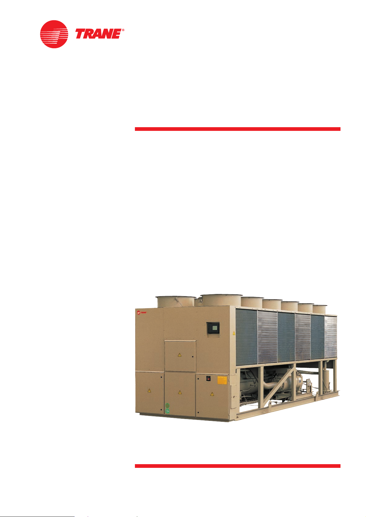
Air-Cooled Series R
™
Helical-Rotary Liquid Chiller
Model RTAC 120 to 200
(400 to 760kw - 50 Hz)
Built for the Industrial and
Commercial Markets
RLC-PRC005-E4
Page 2
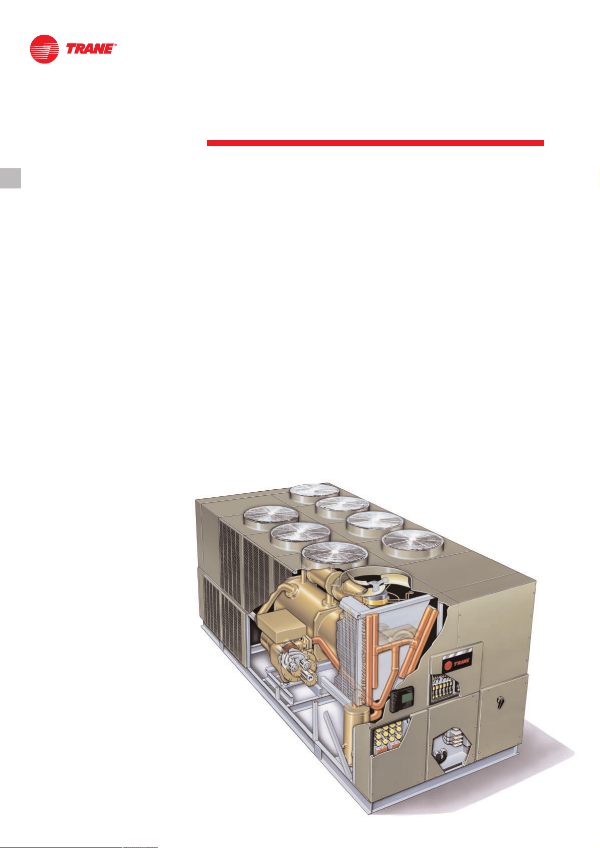
The new Trane Model RTAC Air-Cooled
Helical-Rotary Chiller is the result of a
search for higher reliability, higher
energy efficiency, and lower sound
levels for today’s environment.
In an effort to reduce energy consumed
by HVAC equipment and to continually
produce chilled water, Trane has
developed the Model RTAC chiller with
higher efficiencies and a more reliable
design than any other air cooled chiller
available on the market today.
The Model RTAC chiller uses the proven
design of the Trane helical-rotary
compressor, which embraces all of the
design features that have made the
Trane helical-rotary compressor liquid
chillers such a success since 1987.
Introduction
©American Standard Inc. 2000
RLC-PRC005-E4
Figure 1
What Is New
The RTAC offers the same high
reliability coupled with greatly improved
energy efficiency, vastly reduced
physical footprint, and improved
acoustical performance, due to its
advanced design, low-speed, directdrive compressor, and proven
Series R™ performance.
The major differences between the
Series R, Model RTAC and Model RTAA
are:
• Smaller physical footprint
• Lower sound levels
• Higher energy efficiency
• Designed specifically for operating
with environmentally-safe HFC-134a.
The Series R Model RTAC helical-rotary
chiller is an industrial-grade design, built
for both the industrial and commercial
markets. It is ideal for schools, hospitals,
retailers, office buildings, and industrial
applications.
Page 3

3
RLC-PRC005-E4
Contents
Introduction
Features and Benefits
Improved Acoustical Performance
Simple Installation
Superior Control with Tracer™ Chiller Controls
Options
Application Considerations
Selection Procedure
General Data
Performance Data
Performance Adjustment Factors
Controls
Generic Building Automation System Controls
Typical Wiring Diagrams
Job Site Data
Electrical Data
Dimensional Data
Mechanical Specifications
2
4
9
12
13
19
36
5
6
7
8
33
45
47
50
36
39
44
Page 4

Features and
Benefits
4
RLC-PRC005-E4
Water Chiller Systems Business Unit
The Series R
™
Helical-Rotary Compressor
• Unequaled reliability. The next
generation Trane helical-rotary
compressor is designed, built, and
tested to the same demanding and
rugged standards as the Trane scroll
compressors, the centrifugal
compressors, and the previous
generation helical-rotary compressors
used in both air- and water-cooled
chillers for more than 13 years.
• Years of research and testing. The
Trane helical-rotary compressor has
amassed thousands of hours of
testing, much of it at severe operating
conditions beyond normal commercial
air-conditioning applications.
• Proven track record. The Trane
Company is the world’s largest
manufacturer of large helical-rotary
compressors used for refrigeration.
Over 90,000 compressors worldwide
have proven that the Trane helicalrotary compressor has a reliability rate
of greater than 99.5 percent in the first
year of operation—unequalled in the
industry.
• Resistance to liquid slugging. The
robust design of the Series R
compressor can ingest amounts of
liquid refrigerant that normally would
severely damage reciprocating
compressor valves, piston rods, and
cylinders.
• Fewer moving parts. The helical-rotary
compressor has only two rotating
parts: the male rotor and the female
rotor. Unlike reciprocating
compressors, the Trane helical-rotary
compressor has no pistons,
connecting rods, suction and
discharge valves, or mechanical oil
pump. In fact, a typical reciprocating
compressor has 15 times as many
critical parts as the Series R
compressor. Fewer moving parts leads
to increased reliability and longer life.
• Direct-drive, low-speed, semi-hermetic
compressor for high efficiency and
high reliability.
• Field-serviceable compressor for easy
maintenance.
• Suction-gas-cooled motor. The motor
operates at lower temperatures for
longer motor life.
• Five minute start-to-start and two
minute stop-to-start anti-recycle timer
allows for closer water-loop
temperature control.
Page 5
Improved
Acoustical
Performance
5
RLC-PRC005-E4
The sound levels of the Series R Model
RTAA have been steadily improved
since its introduction. With the advent of
the Model RTAC, sound levels are
reduced significantly by addressing two
major sources: the compressor and the
refrigerant piping. First, the compressor
has been specifically designed to
minimize sound generation. Second, the
refrigerant components and piping have
been optimized to reduce sound
propagation throughout the system. The
result: sound levels achieved on the
Model RTAC represent the lowest sound
levels ever on Trane air-cooled helicalrotary compressor water chillers.
Superior Efficiency Levels:
The Bar Has Been Raised
The standard-efficiency Trane Model
RTAC has COP levels up to 2.90 kW/kW
[9.9 EER] (including fans), while the
premium-efficiency, or high-efficiency,
units leap to COP levels of 3.08 kW/kW
[10.51 EER] (including fans).
The modern technology of the RTAC
with the efficient direct-drive
compressor, the flooded evaporator, the
unique design to separate liquid and
vapor, the electronic expansion valve,
and the revolutionary Tracer
™
Chiller
Controls, has permitted Trane to achieve
these efficiency levels, unmatched in the
industry.
Precise Rotor Tip Clearances
Higher energy efficiency in a helicalrotary compressor is obtained by
reducing the rotor tip clearances. This
next-generation compressor is no
exception. With today’s advanced
manufacturing technology, clearances
can be controlled to even tighter
tolerances. This reduces the leakage
between high- and low-pressure cavities
during compression, allowing for more
efficient compressor operation.
Capacity Control and Load Matching
The combination patented unloading
system on Trane helical-rotary
compressors uses the variable
unloading valve for the majority of the
unloading function. This allows the
compressor to modulate infinitely, to
exactly match building load and to
maintain chilled-water supply
temperatures within ± 0.3°C [±0.5°F] of
the set point. Reciprocating and helicalrotary chillers that rely on stepped
capacity control must run at a capacity
equal to or greater than the load, and
typically can only maintain water
temperature to around ± 1°C [±2°F].
Much of this excess capacity is lost
because overcooling goes toward
removing building latent heat, causing
the building to be dried beyond normal
comfort requirements. When the load
becomes very low, the compressor also
uses a step unloader valve, which is a
single unloading step to achieve the
minimum unloading point of the
compressor. The result of this design is
optimized part-load performance far
superior to single reciprocating
compressors and step-only helicalrotary compressors.
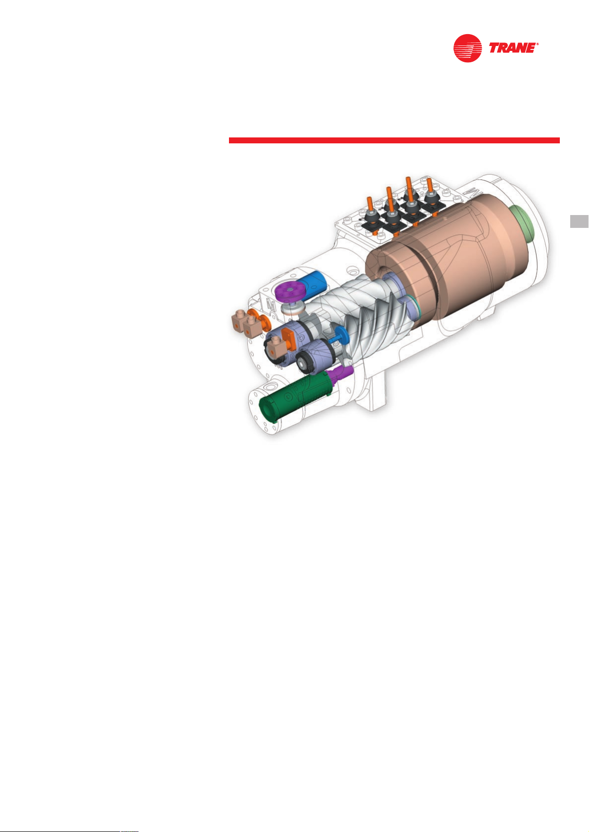
Figure 2 Cutaway of a compressor
Page 6

Simple Installation
6
RLC-PRC005-E4
Compact Physical Size
The Trane Model RTAC chiller averages a
20 percent reduction in physical
footprint, while the greatest change is
actually 40 percent smaller when
compared against the previous design.
This improvement makes the RTAC the
smallest air-cooled chiller in the industry
and a prime candidate for installations
that have space constraints. All physical
sizes were changed without sacrificing
the side clearances needed to supply
fresh airflow without coil starvation—the
tightest operational clearances in the
industry.
Close Spacing Installation
The air-cooled Series R
™
chiller has the
tightest recommended side clearance in
the industry, 1.2 meters, but that is not
all. In situations where equipment must
be installed with less clearance than
recommended, which frequently occurs
in retrofit applications, restricted airflow
is common. Conventional chillers may
not work at all. However, the air-cooled
Series R chiller with the Adaptive
Control
™
microprocessor will make as
much chilled water as possible given the
actual installed conditions, stay on-line
during any unforeseen abnormal
conditions, and optimize its
performance. Consult your Trane sales
engineer for more details.
Factory Testing Means Trouble-Free
Start-up
All air-cooled Series R chillers are given
a complete functional test at the factory.
This computer-based test program
completely checks the sensors, wiring,
electrical components, microprocessor
function, communication capability,
expansion valve performance, and fans.
In addition, each compressor is runtested to verify capacity and efficiency.
Where applicable, each unit is factory
preset to the customer’s design
conditions. An example would be the
leaving-liquid temperature set point. The
result of this test program is that the
chiller arrives at the job site fully tested
and ready for operation.
Factory-Installed and Tested Controls
and Options Speed Installation
All Series R chiller options, including
main power-supply disconnect, low
ambient control, ambient temperature
sensor, low ambient lockout,
communication interface and icemaking controls are factory installed and
tested. Some manufacturers send
accessories in pieces to be field
installed. With Trane, the customer saves
on installation expense and has
assurance that ALL chiller controls and
options have been tested and will
function as expected.
Page 7
Superior Control with
Tracer™Chiller Controls
7
RLC-PRC005-E4
The End of Nuisance
Trip-Outs and
Unnecessary Service Calls?
The Adaptive Control
™
microprocessor
system enhances the air-cooled Series R
chiller by providing the very latest chiller
control technology. With the Adaptive
Control microprocessor, unnecessary
service calls and unhappy tenants are
avoided. The unit does not nuisance-trip
or unnecessarily shut down. Only when
the Tracer chiller controls have
exhausted all possible corrective
actions, and the unit is still violating an
operating limit, will the chiller shut
down. Controls on other equipment
typically shut down the chiller, usually
just when it is needed the most.
For Example:
A typical five-year-old chiller with dirty
coils might trip out on high-pressure
cutout on a 38°C [100°F] day in August.
A hot day is just when comfort cooling
is needed the most. In contrast, the aircooled Series R chiller with an Adaptive
Control microprocessor will stage fans
on, modulate the electronic expansion
valve, and modulate the slide valve as it
approaches a high-pressure cutout,
thereby keeping the chiller on line when
you need it the most.
System Options: Ice Storage
Trane air-cooled chillers are well-suited
for ice production. The unique ability to
operate at decreased ambient
temperature while producing ice results
in approximately the same amount of
work for the compressor. An air-cooled
machine typically switches to ice
production at night. Two things happen
under this assumption. First, the leaving
brine temperature from the evaporator
4. Freeze ice storage
5. Freeze ice storage when comfort
cooling is required
6. Off
Tracer optimization software controls
operation of the required equipment
and accessories to easily move from
one mode of operation to another. For
example: even with ice-storage systems,
there are numerous hours when ice is
neither produced nor consumed, but
saved. In this mode, the chiller is the
sole source of cooling. For example, to
cool the building after all ice is produced
but before high electrical-demand
charges take effect, Tracer sets the aircooled chiller leaving-fluid set point to
its most efficient setting and starts the
chiller, chiller pump, and load pump.
When electrical demand is high, the ice
pump is started and the chiller is either
demand limited or shut down
completely. Tracer controls have the
intelligence to optimally balance the
contribution of the ice and the chiller in
meeting the cooling load.
The capacity of the chiller plant is
extended by operating the chiller and ice
in tandem. Tracer rations the ice,
augmenting chiller capacity while
reducing cooling costs. When ice is
produced, Tracer will lower the aircooled chiller leaving-fluid set point and
start the chiller, ice and chiller pumps,
and other accessories. Any incidental
loads that persists while producing ice
can be addressed by starting the load
pump and drawing spent cooling fluid
from the ice storage tanks.
For specific information on ice storage
applications, contact your local Trane
sales office.
is lowered to around -5.5 to -5°C [22 to
24°F]. Second, the ambient temperature
has typically dropped about 8.3 to 11°C
[15 to 20°F] from the peak daytime
ambient. This effectively places a lift on
the compressors that is similar to
daytime running conditions. The chiller
can operate in lower ambient at night
and successfully produce ice to
supplement the next day’s cooling
demands.
The Model RTAC produces ice by
supplying ice storage tanks with a
constant supply of glycol solution. Aircooled chillers selected for these lower
leaving-fluid temperatures are also
selected for efficient production of
chilled fluid at nominal comfort-cooling
conditions. The ability of Trane chillers to
serve “double duty” in ice production
and comfort cooling greatly reduces the
capital cost of ice-storage systems.
When cooling is required, ice-chilled
glycol is pumped from the ice storage
tanks directly to the cooling coils. No
expensive heat exchanger is required.
The glycol loop is a sealed system,
eliminating expensive annual chemical
treatment costs. The air-cooled chiller is
also available for comfort-cooling duty
at nominal cooling conditions and
efficiencies. The modular concept of
glycol ice-storage systems, and the
proven simplicity of Trane Tracer
™
controls, allow the successful blend of
reliability and energy-saving
performance in any ice-storage
application.
The ice-storage system is operated in
six different modes, each optimized for
the utility cost at a particular time of day.
1. Provide comfort cooling with chiller
2. Provide comfort cooling with ice
3. Provide comfort cooling with ice and
chiller
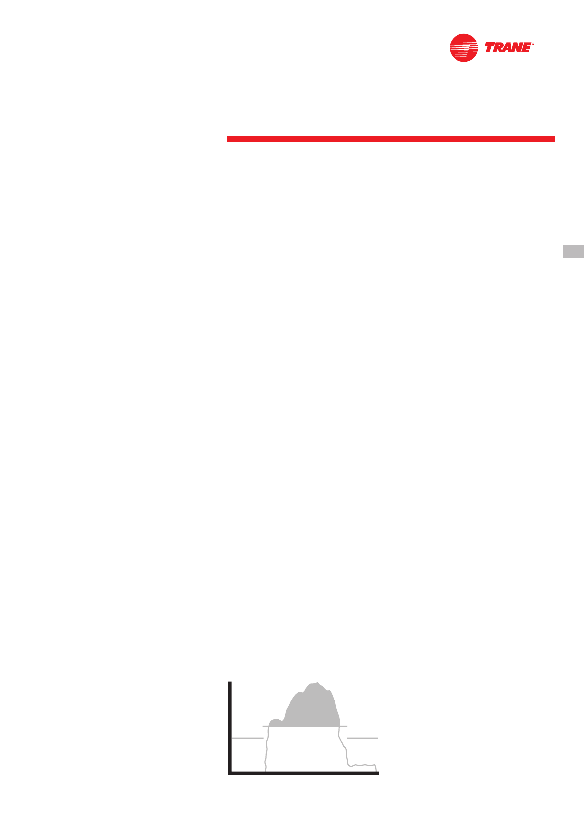
Figure 3 — Ice storage demand cost savings
MN 6 A.M. NOON 6 P.M. MN
ICE
CHILLER
LOAD
Page 8

Premium Efficiency and
Performance Option
This option provides oversized heat
exchangers with two purposes. One, it
allows the unit to be more energy
efficient. Two, the unit will have
enhanced operation in high-ambient
conditions.
Low-Temperature Brine
The hardware and software on the unit
are factory set to handle lowtemperature brine applications, typically
below 5°C [41°F].
Ice Making
The unit controls are factory set to
handle ice making for thermal storage
applications.
Tracer Summit™ Communication
Interface
Permits bi-directional communication to
the Trane Integrated Comfort™ system.
Remote Input Options
Permits remote chilled-liquid set point,
remote current-limit set point, or both,
by accepting a 4-20 mA or 2-10 VDC
analog signal.
Remote Output Options
Permits alarm relay outputs, ice-making
outputs, or both.
Chilled-Water Reset
This option provides the control logic
and field-installed sensors to reset
leaving-chilled-water temperature. The
set point can be reset based on either
ambient temperature or return
evaporator-water temperature.
Night Noise Setback
At night, on contact closure all the fans
run at low speed, bringing the overall
sound level further down.
SCR (Short-Circuit Rating)
Offers a measure of safety for what the
starter-panel enclosure is able to
withstand in the event of an explosion
caused by a short circuit; protection up
to 35,000 amps is available on most
voltages.
Neoprene Isolators
Isolators provide isolation between the
chiller and the structure to help
eliminate vibration transmission.
Neoprene isolators are more effective
and recommended over spring
isolators.
Victaulic Connection Kit
Provides a kit that includes a set of two
pipe stubs and Victaulic couplings.
Low Noise Version
The unit is equipped with low-speed
fans and a compressor soundattenuating enclosure. All the
sound-emitting parts, like refrigerant
lines and panels subject to vibration, are
acoustically treated with soundabsorbent material.
Evaporator Freeze Protection
Factory-installed and -wired trace
heaters on the water boxes and on the
intermediate tube plate, with an ambient
thermostat and protected by a circuit
breaker.
Ground Fault Detection
Sensing ground current for improved
chiller protection.
Protection Grilles
Protection grilles cover the complete
condensing coils and the service areas
beneath the coils.
Coil Protection
A coated wire mesh that covers the
condenser coils only.
Access Protection
A coated wire mesh that covers the
access area underneath the condenser
coils.
Service Valves
Provides a service valve on the suction
and discharge lines of each circuit to
facilitate compressor servicing.
High-Ambient Option
The high-ambient option consists of
special control logic to permit highambient (up to 52°C [125°F]) operation.
This option offers the best performance
when coupled with the premium
efficiency and performance option.
Low-Ambient Option
The low-ambient option consists of
special control logic and fans to permit
low-ambient (down to -23°C [-9°F])
operation.
Low-Ambient Lockout
A factory-installed ambient sensor and
control logic will prevent starting below
the recommended ambient
temperature.
Power Disconnect Switch
A disconnect switch with a through-thedoor handle, plus compressor
protection fuses, is provided to
disconnect main power.
Options
8
RLC-PRC005-E4
Page 9
Application Considerations
9
RLC-PRC005-E4
Certain application constraints should
be considered when sizing, selecting,
and installing Trane air-cooled Series R
chillers. Unit and system reliability is
often dependent on properly and
completely complying with these
considerations. When the application
varies from the guidelines presented, it
should be reviewed with your local
Trane sales engineer.
Unit Sizing
Unit capacities are listed in the
performance data section. Intentionally
oversizing a unit to ensure adequate
capacity is not recommended. Erratic
system operation and excessive
compressor cycling are often a direct
result of an oversized chiller. In addition,
an oversized unit is usually more
expensive to purchase, install, and
operate. If oversizing is desired, consider
using two units.
Water Treatment
Dirt, scale, products of corrosion, and
other foreign material will adversely
affect heat transfer between the water
and system components. Foreign matter
in the chilled-water system can also
increase pressure drop and,
consequently, reduce water flow. Proper
water treatment must be determined
locally, depending on the type of system
51°C [125°F], and selecting the lowambient option will increase the
operational capability of the water chiller
to ambient temperatures as low as 18°C
[0°F]. For operation outside of these
ranges, contact the local Trane sales
office.
Water Flow Limits
The minimum water flow rates are
given in Tables G-1 and G-2. Evaporator
flow rates below the tabulated values
will result in laminar flow and cause
freeze-up problems, scaling,
stratification, and poor control. The
maximum evaporator water flow rate is
also given in the general data section.
Flow rates exceeding those listed may
result in excessive tube erosion.
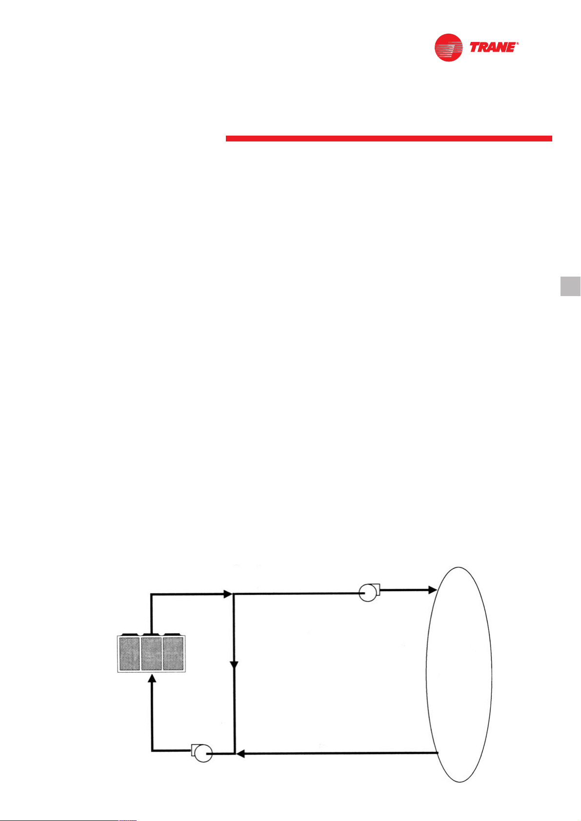
Flow Rates Out of Range
Many process cooling jobs require flow
rates that cannot be met with the
minimum and maximum published
values within the Model RTAC
evaporator. A simple piping change can
alleviate this problem. For example: a
plastic injection molding process
requires 5.0 Lps [80 gpm] of 10°C [50°F]
water and returns that water at 15.6°C
[60°F]. The selected chiller can operate at
these temperatures, but has a minimum
flow rate of 7.6 Lps [120 gpm]. The
following system can satisfy the process.
and local water characteristics. Neither
salt nor brackish water is recommended
for use in Trane air-cooled Series R
chillers. Use of either will lead to a
shortened chiller life. The Trane
Company encourages the employment
of a reputable water-treatment specialist,
familiar with local water conditions, to
assist in this determination and in the
establishment of a proper watertreatment program.
Effect of Altitude on Capacity
Air-cooled Series R chiller capacities
given in the performance data tables are
for use at sea level. At elevations
substantially above sea level, the
decreased air density will reduce
condenser capacity and, therefore, unit
capacity and efficiency. The adjustment
factors in Table F-1 can be applied
directly to the catalog performance data
to determine the unit’s adjusted
performance.
Ambient Limitations
Trane air-cooled Series R chillers are
designed for year-round operation over
a range of ambient temperatures. The
air-cooled Model RTAC chiller will
operate in ambient temperatures of 4 to
46°C [25 to 115°F]. Selecting the highambient option will allow the chiller to
operate in ambient temperatures of
10°C
7.6 Lps
13.7°C
7.6 Lps
CV pump
7.5 Lps
10°C
2.5 Lps
CV Pump
5 Lps
10°C
5 Lps
15.6°C
5 Lps
Figure 4 — GPM Out of Range
Load
Page 10
Application Considerations
10
RLC-PRC005-E4
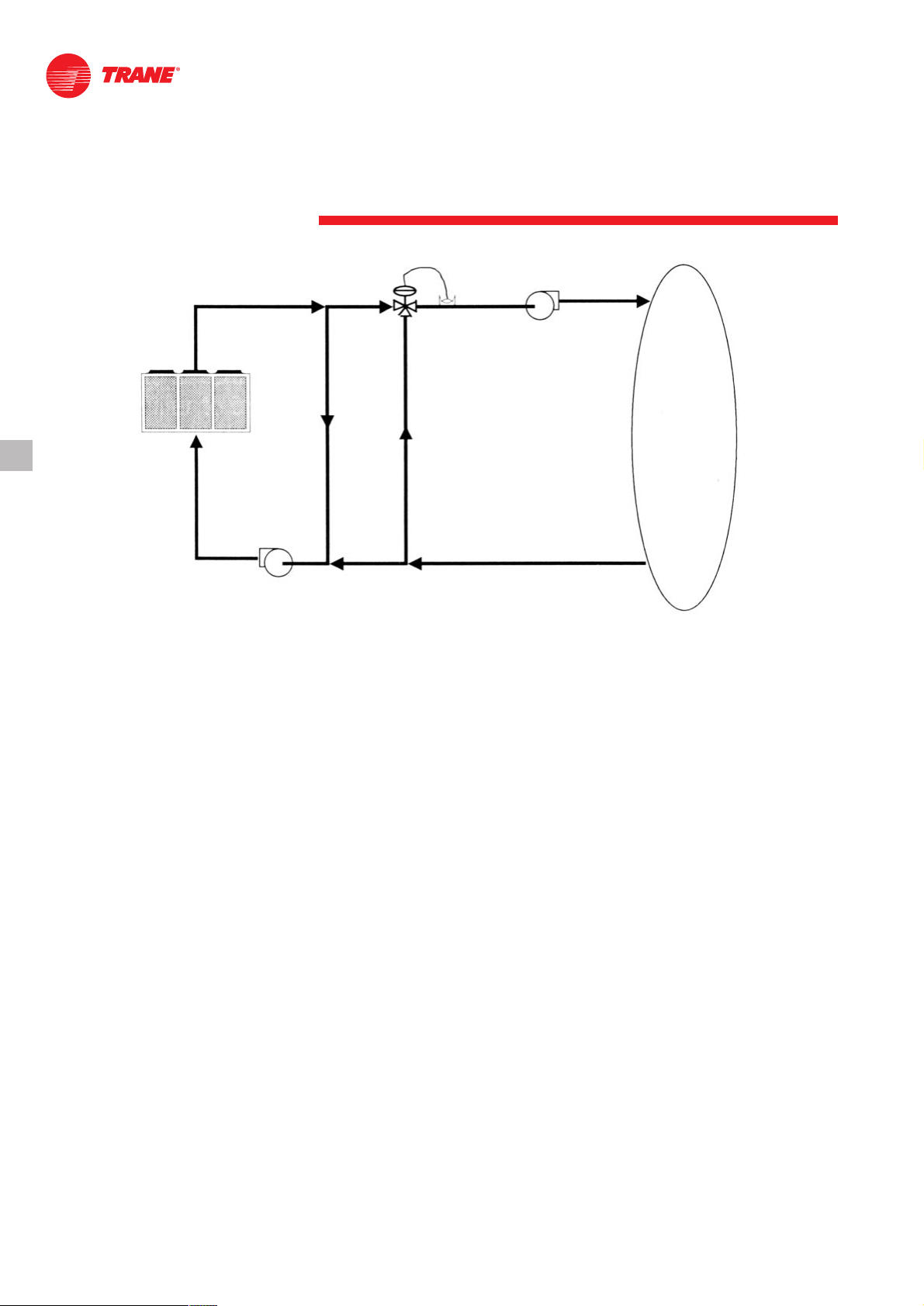
15.6°C
7.6 Lps
21°C
7.6 Lps
CV Pump
15°C
5.4 Lps
35°C
5.4 Lps
35°C
7.6 Lps
29.4°C
7.6 Lps
15.6°C
2.2 Lps
35°C
2.2 Lps
Figure 5 — GPM Out of Range
Leaving-Water Temperature Range
Trane air-cooled Series R chillers have
three distinct leaving-water categories:
standard, low temperature, and ice
making. The standard leaving-solution
temperature range is 4.4 to 15.6°C [40 to
60°F]. Low-temperature machines
produce leaving-liquid temperatures
less than 4.4°C [40°F]. Since liquid
supply temperature set points less than
4.4°C [40°F] result in suction
temperatures at or below the freezing
point of water, a glycol solution is
required for all low-temperature
machines. Ice-making machines have a
leaving-liquid temperature range of -6.7
to 15.6°C [20 to 60°F]. Ice-making
controls include dual set point controls
and safeties for ice making and standard
cooling capabilities. Consult your local
Trane sales engineer for applications or
selections involving low temperature or
ice making machines. The maximum
water temperature that can be circulated
through an evaporator when the unit is
not operating is 42°C [108°F].
Leaving-Water Temperature
Out of Range
Similar to the flow rates above, many
process cooling jobs require
temperature ranges that cannot be met
with the minimum and maximum
published values for the Model RTAC
evaporator. A simple piping change can
alleviate this problem. For example: a
laboratory load requires 7.6 Lps [120
gpm] of water entering the process at
29.4°C [85°F] and returning at 35°C
[95°F]. The accuracy required is higher
than the cooling tower can give. The
selected chiller has adequate capacity,
but has a maximum leaving-chilledwater temperature of 15.6°C [60°F].
In the example shown, both the chiller and
process flow rates are equal. This is not
necessary. For example, if the chiller had a
higher flow rate, there would be more water
bypassing and mixing with warm water.
Supply-Water Temperature Drop
The performance data for the Trane aircooled Series R chiller is based on a
chilled-water temperature drop of 6°C
[10.8°F]. Chilled-water temperature
drops from 3.3 to 10°C [6 to 18°F] may
be used as long as minimum and
maximum water temperature, and
minimum and maximum flow rates, are
not violated. Temperature drops outside
this range are beyond the optimum
range for control, and may adversely
affect the microcomputer’s ability to
maintain an acceptable supply-water
temperature range. Further, temperature
drops of less than 3.3°C [6°F] may result
in inadequate refrigerant superheat.
Sufficient superheat is always a primary
concern in any direct-expansion
refrigerant system and is especially
important in a package chiller where the
evaporator is closely coupled to the
compressor. When temperature drops
are less than 3.3°C [6°F], an evaporator
runaround loop may be required.
Load
CV Pump
Page 11

Application Considerations
11
RLC-PRC005-E4
Variable Flow in the Evaporator
An attractive chilled-water system
option may be a variable primary flow
(VPF) system. VPF systems present
building owners with several costsaving benefits that are directly related
to the pumps. The most obvious cost
savings result from eliminating the
secondary distribution pump, which in
turn avoids the expense incurred with
the associated piping connections
(material, labor), electrical service, and
variable-frequency drive. Building
owners often cite pump-related energy
savings as the reason that prompted
them to install a VPF system. With the
help of a software analysis tool such as
System Analyzer
™
, TRACE™, or DOE-2,
you can determine whether the
anticipated energy savings justify the
use of variable primary flow in a
particular application. It may also be
easier to apply variable primary flow in
an existing chilled-water plant. Unlike
the “decoupled” design, the bypass can
be positioned at various points in the
chilled-water loop and an additional
pump is unnecessary. The evaporator in
the Model RTAC can withstand up to 50
percent water flow reduction as long as
this flow is equal to or above the
minimum flow-rate requirements. The
microprocessor and capacity control
algorithms are designed to take a
minimum of 10 percent change in water
flow rate per minute.
Short Water Loops
The proper location of the temperature
control sensor is in the supply (outlet)
water connection or pipe. This location
allows the building to act as a buffer and
assures a slowly-changing return-water
temperature. If there is not a sufficient
volume of water in the system to
provide an adequate buffer, temperature
control can be lost, resulting in erratic
system operation and excessive
compressor cycling. A short water loop
has the same effect as attempting to
control using the building return water.
Typically, a two-minute water loop is
sufficient to prevent a short water loop.
Therefore, as a guideline, ensure that
the volume of water in the evaporator
loop equals or exceeds two times the
evaporator flow rate. For a rapidly
changing load profile, the amount of
volume should be increased. To prevent
the effect of a short water loop, the
following item should be given careful
consideration: a storage tank or larger
header pipe to increase the volume of
water in the system and, therefore,
reduce the rate of change of the return
water temperature.
Applications Types
• Comfort cooling
• Industrial process cooling
• Ice or thermal storage
• Low-temperature process cooling.
Ice Storage Provides
Reduced Electrical Demand
An ice-storage system uses a standard
chiller to make ice at night, when utilities
charge less for electricity. The ice
supplements, or even replaces,
mechanical cooling during the day,
when utility rates are at their highest.
This reduced need for cooling results in
big utility cost savings.
Another advantage of ice storage is
standby cooling capacity. If the chiller is
unable to operate, one or two days of
ice may still be available to provide
cooling. In that period of time, the chiller
can be repaired before building
occupants feel any loss of comfort.
The Trane Model RTAC chiller is uniquely
suited to low-temperature applications
like ice storage because of the ambient
relief experienced at night. This allows
the Model RTAC chiller to produce ice
efficiently, with less stress on the
machine.
Simple and smart control strategies are
another advantage the Model RTAC
chiller offers for ice-storage applications.
Trane Tracer
™
building management
systems can actually anticipate how
much ice needs to be made at night,
and operate the system accordingly. The
controls are integrated right into the
chiller. Two wires and preprogrammed
software dramatically reduce field
installation cost and complex
programming.
Page 12

Selection Procedure
12
RLC-PRC005-E4
The chiller capacity tables cover the
most frequently encountered leavingliquid temperatures. The tables reflect a
6°C [10.8°F] temperature drop through
the evaporator. For other temperature
drops, apply the appropriate
performance data adjustment factors.
For chilled brine selections, refer to
Figures F-3 and F-4 for ethylene and
propylene glycol adjustment factors.
To select a Trane air-cooled Series R
™
chiller, the following information is
required:
Selection Procedure SI Units
The chiller capacity tables P-1 through
P-4 cover the most frequently
encountered leaving-water
temperatures. The tables reflect a 6°C
temperature drop through the
evaporator
To select a Trane air-cooled RTAC chiller,
the following information is required:
1
Design load in kW of refrigeration
2
Design chilled-water temperature drop
3
Design leaving-chilled-water
temperature
4
Design ambient temperature
Evaporator flow rates can be
determined by using the following
formula:
Lps = kW (capacity) x 0.239 ÷
temperature drop (°C)
To determine the evaporator pressure
drop we use the flow rate (Lps) and the
evaporator water pressure drop Figure
F1.
For selection of chilled brine units, or
applications where the altitude is
significantly greater than sea level or the
temperature drop is different than 6°C,
the performance adjustment factors
from Table F-1 should be applied at this
point.
For example:
Corrected Capacity = Capacity
(unadjusted) x Glycol Capacity
Adjustment Factor
Corrected Flow Rate = Flow Rate
(unadjusted) x Glycol Flow Rate
Adjustment Factor
5
The final unit selection is:
• Quantity (1) RTAA 140
• Cooling capacity = 505.9 kW
• Design ambient temperature 35°C
• Entering chilled-water
temperatures = 12°C
• Leaving chilled-water
temperatures = 7°C
• Chilled-water flow rate = 24.2 Lps
• Evaporator water pressure
drop = 53 kPa
• Compressor power input = 159 kW
• Unit COP = 2.9 kW/kW
Contact the local Trane sales engineer
for a proper selection at the given
operating conditions.
For a selection in English units:
• 1 ton = 3.5168 kW
• Evaporator flow rate in gpm =
24 x tons ÷ delta T (°F)
• Delta T (°F) = delta T (°C) x 1.8
• 1 gpm = 0.06309 Lps
• 1 ft WG = 3 kPa
• EER = COP ÷ 0.293
Page 13

General Data
13
RLC-PRC005-E4
SI Units
Table G-1 — RTAC Standard
Size 140 155 170 185 200
Compressor
Quantity 2 2 2 2 2
Nominal Size (1) tons 70/70 70/85 85/85 85/100 100/100
Evaporator
Evaporator Model F140 F155 F170 F185 F200
Water Storage L 132.3 141.3 150.7 156 163.5
Minimum Flow Lps 10.8 11.5 12.5 13.6 13.6
Maximum Flow Lps 33.1 38.2 43.1 39.5 48.4
Condenser
Qty of Coils 4 4 4 4 4
Coil Length mm 3962/3962 4572/3962 4572/4572 5486/4572 5486/5486
Coil Height mm 1067 1067 1067 1067 1067
Fin series fins/ft 192 192 192 192 192
Number of Rows 3 3 3 3 3
Condenser Fans
Quantity (1) 4/4 5/4 5/5 6/5 6/6
Diameter mm 762 762 762 762 762
Total Air Flow m3/s 35.82 39.53 43.22 47.55 51.88
Nominal RPM 915 915 915 915 915
Tip Speed m/s 36.48 36.48 36.48 36.48 36.48
Motor kW kW 1.9 1.9 1.9 1.9 1.9
Min Starting/Operating Ambient(2)
Standard Unit °C -4 -4 -4 -4 -4
Low-Ambient Unit °C -23 -23 -23 -23 -23
General Unit
Refrigerant HFC 134a HFC 134a HFC 134a HFC 134a HFC 134a
Number of Independent
Refrigerant Circuits 2 2 2 2 2
% Minimum Load (3) 15 15 15 15 15
Refrigerant Charge (1) kg 65.8/65.8 70.3/65.8 70.3/70.3 99.8/95.3 99.8/99.8
Oil Charge (1) L 7.6/7.6 7.6/7.6 7.6/7.6 9.9/7.6 9.9/9.9
Operating Weight kg 5216 5407 5586 6268 6396
Shipping Weight kg 5107 5265 5434 6111 6232
Table G-2 — RTAC High Efficiency
Size 120 130 140 155 170 185 200
Compressor
Quantity 2 2 2 2 2 2 2
Nominal Size (1) tons 60/60 60/70 70/70 70/85 85/85 85/100 100/100
Evaporator
Evaporator Model F140 F155 F170 F185 F200 F220 F240
Water Storage L 132.3 141.3 150.7 156 163.5 175.9 188.3
Minimum Flow Lps 10.8 11.5 12.5 13.6 13.6 14.9 16.3
Maximum Flow Lps 33.1 38.2 43.3 39.5 48.4 53.5 58.6
Condenser
Qty of Coils 4 4 4 4 4 4 4
Coil Length mm 3962/3962 4572/3962 4572/4572 5486/4572 5486/5486 6400/2486 6400/6400
Coil Height mm 1067 1067 1067 1067 1067 1067 1067
Fin series fins/ft 192 192 192 192 192 192 192
Number of Rows 3 3 3 3 3 3 3
Condenser Fans
Quantity (1) 4/4 5/4 5/5 6/5 6/6 7/6 7/7
Diameter mm 762 762 762 762 762 762 762
Total Air Flow m3/s 35.82 39.53 43.22 47.55 51.88 56.17 60.47
Nominal RPM 915 915 915 915 915 915 915
Tip Speed m/s 36.48 36.48 36.48 36.48 36.48 36.48 36.48
Motor kW kW 1.9 1.9 1.9 1.9 1.9 1.9 1.9
Min Starting/Operating Ambient(2)
Standard Unit °C -4 -4 -4 -4 -4 -4 -4
Low-Ambient Unit °C -23 -23 -23 -23 -23 -23 -23
General Unit
Refrigerant HFC 134a HFC 134a HFC 134a HFC 134a HFC 134a HFC 134a HFC 134a
Number of Independent
Refrigerant Circuits 2 2 2 2 2 2 2
% Minimum Load (3) 15 15 15 15 15 15 15
Refrigerant Charge (1) kg 65.8/65.8 70.3/65.8 70.3/70.3 99.8/95.3 99.8/99.8 104.4/99.8 104.4/104.4
Oil Charge (1) L 7.6/7.6 7.6/7.6 7.6/7.6 7.6/7.6 7.6/7.6 9.9/7.6 9.9/9.9
Operating Weight kg 5198 5271 5274 6073 6323 6555 6759
Shipping Weight kg 5089 5129 5122 5916 6159 6378 6569
Page 14

General Data
14
RLC-PRC005-E4
SI Units
Table G-3 — RTAC Low Noise Standard
Size 140 155 170 185 200
Compressor
Quantity 2 2 2 2 2
Nominal Size (1) tons 70/70 70/85 85/85 85/100 100/100
Evaporator
Evaporator Model F140 F155 F170 F185 F200
Water Storage L 132.3 141.3 150.7 156 163.5
Minimum Flow Lps 10.8 11.5 12.5 13.6 13.6
Maximum Flow Lps 33.1 38.2 43.1 39.5 48.4
Condenser
Qty of Coils 4 4 4 4 4
Coil Length mm 3962/3962 4572/3962 4572/4572 5486/4572 5486/5486
Coil Height mm 1067 1067 1067 1067 1067
Fin series fins/ft 192 192 192 192 192
Number of Rows 3 3 3 3 3
Condenser Fans
Quantity (1) 4/4 5/4 5/5 6/5 6/6
Diameter mm 762 762 762 762 762
Total Air Flow m3/s 25.61 28.27 30.93 34.02 37.11
Nominal RPM 680 680 680 680 680
Tip Speed m/s 27.5 27.5 27.5 27.5 27.5
Motor kW kW 0.85 0.85 0.85 0.85 0.85
Min Starting/Operating Ambient(2)
Standard Unit °C -4 -4 -4 -4 -4
Low-Ambient Unit °C -23 -23 -23 -23 -23
General Unit
Refrigerant HFC 134a HFC 134a HFC 134a HFC 134a HFC 134a
Number of Independent
Refrigerant Circuits 2 2 2 2 2
% Minimum Load (3) 15 15 15 15 15
Refrigerant Charge (1) kg 65.8/65.8 70.3/65.8 70.3/70.3 99.8/95.3 99.8/99.8
Oil Charge (1) L 7.6/7.6 7.6/7.6 7.6/7.6 9.9/7.6 9.9/9.9
Operating Weight kg 5306 5497 5676 6358 6486
Shipping Weight kg 5197 5355 5524 6201 6322
Page 15

15
RLC-PRC005-E4
Table G-4 — RTAC High Efficiency Low Noise
Size 120 130 140 155 170 185 200
Compressor
Quantity 2 2 2 2 2 2 2
Nominal Size (1) tons 60/60 60/70 70/70 70/85 85/85 85/100 100/100
Evaporator
Evaporator Model F140 F155 F170 F185 F200 F220 F240
Water Storage L 132.3 141.3 150.7 156 163.5 175.9 188.3
Minimum Flow Lps 10.8 11.5 12.5 13.6 13.6 14.9 16.3
Maximum Flow Lps 33.1 38.2 43.3 39.5 48.4 53.5 58.6
Condenser
Qty of Coils 4 4 4 4 4 4 4
Coil Length mm 3962/3962 4572/3962 4572/4572 5486/4572 5486/5486 6400/2486 6400/6400
Coil Height mm 1067 1067 1067 1067 1067 1067 1067
Fin series fins/ft 192 192 192 192 192 192 192
Number of Rows 3 3 3 3 3 3 3
Condenser Fans
Quantity (1) 4/4 5/4 5/5 6/5 6/6 7/6 7/7
Diameter mm 762 762 762 762 762 762 762
Total Air Flow m3/s 25.61 28.27 30.93 34.02 37.11 40.23 43.34
Nominal RPM 680 680 680 680 680 680 680
Tip Speed m/s 27.5 27.5 27.5 27.5 27.5 27.5 27.5
Motor kW kW 0.85 0.85 0.85 0.85 0.85 0.85 0.85
Min Starting/Operating Ambient(2)
Standard Unit °C -4 -4 -4 -4 -4 -4 -4
Low-Ambient Unit °C -23 -23 -23 -23 -23 -23 -23
General Unit
Refrigerant HFC 134a HFC 134a HFC 134a HFC 134a HFC 134a HFC 134a HFC 134a
Number of Independent
Refrigerant Circuits 2 2 2 2 2 2 2
% Minimum Load (3) 15 15 15 15 15 15 15
Refrigerant Charge (1) kg 65.8/65.8 70.3/65.8 70.3/70.3 99.8/95.3 99.8/99.8 104.4/99.8 104.4/104.4
Oil Charge (1) L 7.6/7.6 7.6/7.6 7.6/7.6 7.6/7.6 7.6/7.6 9.9/7.6 9.9/9.9
Operating Weight kg 5288 5361 5364 6163 6413 6645 6849
Shipping Weight kg 5179 5219 5212 60 06 6249 6468 6659
Notes:
1. Data containing information on two circuits shown as follows: ckt1/ckt2
2. Minimum start-up/operation ambient based on a 2.22 m/s (5mph) wind across the condenser.
3. Percent minimum load is for total machine at 10°C (50°F) ambient and 7°C (44°F) leaving chilled water temperature. Not each individual circuit.
SI Units
General Data
Page 16

16
RLC-PRC005-E4
General Data
English Units
Table G-5 — RTAC Standard
Size 140 155 170 185 200
Compressor
Quantity 2 2 2 2 2
Nominal Size (1) tons 70/70 70/85 85/85 85/100 100/100
Evaporator
Evaporator Model F140 F155 F170 F185 F200
Water Storage gal 35 37.3 39.8 41.2 43.2
Minimum Flow gpm 171.2 182.3 198.2 215.6 215.6
Maximum Flow gpm 524.7 605.6 683.2 626.2 767.2
Condenser
Quantity of Coils 4 4 4 4 4
Coil Length ft 13/13 15/13 15/15 18/15 18/18
Coil Height ft 3.5 3.5 3.5 3.5 3.5
Fin Series fins/ft 192 192 192 192 192
Number of Rows 3 3 3 3 3
Condenser Fans
Quantity (1) 4/4 5/4 5/5 6/5 6/6
Diameter in. 30 30 30 30 30
Total Air Flow cfm 75867 83725 91540 100710 109882
Nominal RPM 915 915 915 915 915
Tip Speed ft/s 120 120 120 120 120
Motor kW kW 1.9 1.9 1.9 1.9 1.9
Minimum Starting/Operating Ambient(2)
Standard Unit °F 25 25 25 25 25
Low-Ambient Unit °F -9 -9 -9 -9 -9
General Unit
Refrigerant HFC 134a HFC 134a HFC 134a HFC 134a HFC 134a
Number of Independent
Refrigerant Circuits 2 2 2 2 2
% Minimum Load (3) 15 15 15 15 15
Refrigerant Charge (1) lb 145/145 155/145 155/155 220/210 220/220
Oil Charge (1) gal 2/2 2.2 2.2 2.6/2 2.6/2.6
Operating Weight lb 12018 12459 12871 14442 14737
Shipping Weight lb 11767 12131 12521 14081 14359
Table G-6 — RTAC High Efficiency
Size 120 130 140 155 170 185 200
Compressor
Quantity 2 2 2 2 2 2 2
Nominal Size (1) tons 60/60 60/70 70/70 70/85 85/85 85/100 100/100
Evaporator
Evaporator Model F140 F155 F170 F185 F200 F220 F240
Water Storage gal 35 37.3 39.8 41.2 43.2 46.5 49.8
Minimum Flow gpm 171.2 182.3 198.2 215.6 215.6 231.4 258.4
Maximum Flow gpm 524.7 605.6 683.2 626.2 767.2 848.1 928.9
Condenser
Quantity of Coils 4 4 4 4 4 4 4
Coil Length ft 13/13 15/13 15/15 18/15 18/18 21/18 21/21
Coil Height ft 3.5 3.5 3.5 3.5 3.5 3.5 3.5
Fin Series fins/ft 192 192 192 192 192 192 192
Number of Rows 3 3 3 3 3 3 3
Condenser Fans
Quantity (1) 4/4 5/4 5/5 6/5 6/6 7/6 7/7
Diameter in. 30 30 30 30 30 30 30
Total Air Flow cfm 75867 83725 91540 100710 109882 118968 128075
Nominal RPM 915 915 915 915 915 915 915
Tip Speed ft/s 120 120 120 120 120 120 120
Motor kW kW 1.9 1.9 1.9 1.9 1.9 1.9 1.9
Minimum Starting/Operating Ambient(2)
Standard Unit °F 25 25 25 25 25 25 25
Low-Ambient Unit °F -9 -9 -9 -9 -9 -9 -9
General Unit
Refrigerant HFC 134a HFC 134a HFC 134a HFC 134a HFC 134a HFC 134a HFC 134a
Number of Independent
Refrigerant Circuits 2 2 2 2 2 2 2
% Minimum Load (3) 15 15 15 15 15 15 15
Refrigerant Charge (1) lb 145/145 155/145 155/155 220/210 220/220 230/220 230/230
Oil Charge (1) gal 2/2 2.2 2.2 2.6/2 2.6/2.6 2.6/2 2.6/2.6
Operating Weight lb 11977 12145 12152 13993 14569 15104 15574
Shipping Weight lb 11726 11818 11802 13631 14191 14696 15136
Page 17

17
RLC-PRC005-E4
General Data
English Units
Table G-7 — RTAC Low Noise Standard
Size 140 155 170 185 200
Compressor
Quantity 2 2 2 2 2
Nominal Size (1) tons 70/70 70/85 85/85 85/100 100/100
Evaporator
Evaporator Model F140 F155 F170 F185 F200
Water Storage gal 35 37.3 39.8 41.2 43.2
Minimum Flow gpm 171.2 182.3 198.2 215.6 215.6
Maximum Flow gpm 524.7 605.6 683.2 626.2 767.2
Condenser
Quantity of Coils 4 4 4 4 4
Coil Length ft 13/13 15/13 15/15 18/15 18/18
Coil Height ft 3.5 3.5 3.5 3.5 3.5
Fin Series fins/ft 192 192 192 192 192
Number of Rows 3 3 3 3 3
Condenser Fans
Quantity (1) 4/4 5/4 5/5 6/5 6/6
Diameter in. 30 30 30 30 30
Total Air Flow cfm 54242 59876 65510 72054 78600
Nominal RPM 680 680 680 680 680
Tip Speed ft/s 90 90 90 90 90
Motor kW kW 0.85 0.85 0.85 0.85 0.85
Minimum Starting/Operating Ambient(2)
Standard Unit °F 25 25 25 25 25
Low-Ambient Unit °F -9 -9 -9 -9 -9
General Unit
Refrigerant HFC 134a HFC 134a HFC 134a HFC 134a HFC 134a
Number of Independent
Refrigerant Circuits 2 2 2 2 2
% Minimum Load (3) 15 15 15 15 15
Refrigerant Charge (1) lb 145/145 155/145 155/155 220/210 220/220
Oil Charge (1) gal 2/2 2.2 2.2 2.6/2 2.6/2.6
Operating Weight lb 12226 12666 13078 14650 14945
Shipping Weight lb 11975 12339 12728 14288 14567
Page 18

18
RLC-PRC005-E4
General Data
English Units
Table G-8 — RTAC High Efficiency Low Noise
Size 120 130 140 155 170 185 200
Compressor
Quantity 2 2 2 2 2 2 2
Nominal Size (1) tons 60/60 60/70 70/70 70/85 85/85 85/100 100/100
Evaporator
Evaporator Model F140 F155 F170 F185 F200 F220 F240
Water Storage gal 35 37.3 39.8 41.2 43.2 46.5 49.8
Minimum Flow gpm 171.2 182.3 198.2 215.6 215.6 231.4 258.4
Maximum Flow gpm 524.7 605.6 683.2 626.2 767.2 848.1 928.9
Condenser
Quantity of Coils 4 4 4 4 4 4 4
Coil Length ft 13/13 15/13 15/15 18/15 18/18 21/18 21/21
Coil Height ft 3.5 3.5 3.5 3.5 3.5 3.5 3.5
Fin Series fins/ft 192 192 192 192 192 192 192
Number of Rows 3 3 3 3 3 3 3
Condenser Fans
Quantity (1) 4/4 5/4 5/5 6/5 6/6 7/6 7/7
Diameter in. 30 30 30 30 30 30 30
Total Air Flow cfm 54242 59876 65510 72054 78600 85207 91794
Nominal RPM 680 680 680 680 680 680 680
Tip Speed ft/s 90 90 90 90 90 90 90
Motor kW kW 0.85 0.85 0.85 0.85 0.85 0.85 0.85
Minimum Starting/Operating Ambient(2)
Standard Unit °F 25 25 25 25 25 25 25
Low-Ambient Unit °F -9 -9 -9 -9 -9 -9 -9
General Unit
Refrigerant HFC 134a HFC 134a HFC 134a HFC 134a HFC 134a HFC 134a HFC 134a
Number of Independent
Refrigerant Circuits 2 2 2 2 2 2 2
% Minimum Load (3) 15 15 15 15 15 15 15
Refrigerant Charge (1) lb 145/145 155/145 155/155 220/210 220/220 230/220 230/230
Oil Charge (1) gal 2/2 2.2 2.2 2.6/2 2.6/2.6 2.6/2 2.6/2.6
Operating Weight lb 12184 12353 12359 14200 14776 15311 15781
Shipping Weight lb 11933 12025 12009 13839 14399 14903 15343
Notes:
1. Data containing information on two circuits shown as follows: ckt1/ckt2
2. Minimum start-up/operation ambient based on a 5mph wind across the condenser.
3. Percent minimum load is for total machine at 10°C [50°F] ambient and 7°C [44°F] leaving chilled water temperature. Not each individual circuit.
Page 19

19
RLC-PRC005-E4
Performance Data
Standard Units (SI Units)
Table P-1 — RTAC 140 Entering Condenser Air Temperature (°C)
LWT 2 5 30 35 4 0 46 50
°C C.C. P.I. COP C.C. P.I. COP C.C. P.I. COP C.C. P.I. COP C.C. P.I. COP C.C. P.I. COP
kW kW/kW kW kW kW/kW kW kW kW/kW kW kW kW/kW kW kW kW/kW kW kW kW/kW kW
5 536.3 131.3 3.65 505.7 141.8 3.21 474.1 153.5 2.80 441.6 166.5 2.42 400.7 184.0 2.01 374.2 196.1 1.77
7 571.1 136.4 3.75 539.0 147.1 3.31 505.9 159.0 2.90 471.7 172.1 2.51 428.8 189.8 2.09 400.9 202.1 1.84
9 606.9 141.7 3.85 573.2 152.6 3.41 538.4 164.6 2.99 502.6 177.9 2.60 457.6 195.8 2.16 409.6 197.1 1.92
11 643.4 147.2 3.95 608.1 158.2 3.50 571.7 170.4 3.07 534.2 183.9 2.68 486.9 202.0 2.24 417.2 191.3 2.01
13 680.6 152.8 4.04 643.7 164.0 3.58 605.6 176.4 3.15 566.3 190.0 2.75 509.4 204.9 2.31 423.3 184.6 2.11
Table P-2 — RTAC 155 Entering Condenser Air Temperature (°C)
LWT 2 5 30 35 4 0 46 50
°C C.C. P.I. COP C.C. P.I. COP C.C. P.I. COP C.C. P.I. COP C.C. P.I. COP C.C. P.I. COP
kW kW/kW kW kW kW/kW kW kW kW/kW kW kW kW/kW kW kW kW/kW kW kW kW/kW kW
5 587.8 145.8 3.60 554.5 156.9 3.18 520.0 169.4 2.78 484.5 183.2 2.41 440.0 201.9 2.00 411.0 214.9 1.77
7 625.7 151.7 3.70 590.6 163.0 3.27 554.4 175.6 2.87 517.1 189.6 2.50 470.2 208.5 2.08 439.7 221.7 1.84
9 664.3 157.8 3.79 627.5 169.3 3.36 589.5 182.0 2.95 550.3 196.2 2.57 501.1 215.3 2.15 450.5 217.4 1.92
11 703.7 164.1 3.87 665.1 175.7 3.44 625.3 188.7 3.03 584.2 203.0 2.65 532.6 222.3 2.22 454.9 209.3 2.00
13 743.7 170.6 3.95 703.4 182.4 3.52 661.7 195.5 3.10 618.7 209.9 2.72 561.8 225.5 2.31 461.3 202.5 2.10
Table P-3 — RTAC 170 Entering Condenser Air Temperature (°C)
LWT 2 5 30 35 4 0 46 50
°C C.C. P.I. COP C.C. P.I. COP C.C. P.I. COP C.C. P.I. COP C.C. P.I. COP C.C. P.I. COP
kW kW/kW kW kW kW/kW kW kW kW/kW kW kW kW/kW kW kW kW/kW kW kW kW/kW kW
5 640.2 160.5 3.56 603.9 172.2 3.15 566.5 185.4 2.77 527.9 200.0 2.41 479.5 220.0 2.00 448.1 233.9 1.77
7 681.1 167.2 3.65 642.9 179.1 3.24 603.5 192.4 2.85 562.9 207.2 2.48 511.9 227.4 2.07 478.8 241.4 1.84
9 722.7 174.2 3.73 682.6 186.2 3.32 641.2 199.7 2.93 598.6 214.6 2.56 545.0 234.9 2.14 491.5 237.7 1.91
11 765.0 181.4 3.81 723.0 193.5 3.39 679.5 207.2 3.00 634.9 222.2 2.63 578.7 242.7 2.21 497.9 230.3 1.99
13 807.9 188.8 3.88 763.9 201.1 3.46 718.5 214.8 3.07 671.8 230.0 2.69 607.7 245.1 2.30 504.4 222.7 2.08
Table P-4 — RTAC 185 Entering Condenser Air Temperature (°C)
LWT 2 5 30 35 4 0 46 50
°C C.C. P.I. COP C.C. P.I. COP C.C. P.I. COP C.C. P.I. COP C.C. P.I. COP C.C. P.I. COP
kW kW/kW kW kW kW/kW kW kW kW/kW kW kW kW/kW kW kW kW/kW kW kW kW/kW kW
5 708.2 177.3 3.57 669.4 190.2 3.16 629.1 204.6 2.78 587.4 220.8 2.43 534.9 242.8 2.03 500.5 258.0 1.79
7 753.1 184.7 3.66 712.2 197.8 3.25 669.8 212.5 2.86 625.9 228.9 2.50 570.5 251.2 2.09 525.9 261.3 1.86
9 798.8 192.3 3.74 755.9 205.7 3.33 711.3 220.6 2.94 665.2 237.3 2.57 607.0 259.9 2.16 539.2 256.9 1.94
11 845.3 200.2 3.81 800.3 213.8 3.40 753.6 229.0 3.01 705.3 245.9 2.64 644.2 268.9 2.22 548.1 249.3 2.03
13 892.5 208.4 3.88 845.4 222.2 3.47 796.6 237.6 3.08 746.1 254.8 2.70 672.6 271.9 2.29 551.0 238.7 2.12
Table P-5 — RTAC 200 Entering Condenser Air Temperature (°C)
LWT 2 5 30 35 4 0 46 50
°C C.C. P.I. COP C.C. P.I. COP C.C. P.I. COP C.C. P.I. COP C.C. P.I. COP C.C. P.I. COP
kW kW/kW kW kW kW/kW kW kW kW/kW kW kW kW/kW kW kW kW/kW kW kW kW/kW kW
5 777.8 194.3 3.58 736.2 208.3 3.18 692.9 224.2 2.80 647.9 241.8 2.44 591.0 265.7 2.04 553.7 282.4 1.81
7 827.0 202.4 3.66 783.1 216.7 3.26 737.4 232.9 2.88 690.1 250.8 2.52 630.0 275.3 2.11 580.4 285.5 1.88
9 877.0 210.8 3.75 830.9 225.5 3.34 782.9 241.9 2.95 733.1 260.2 2.59 670.1 285.1 2.17 588.7 276.7 1.96
11 928.0 219.5 3.82 879.7 234.5 3.41 829.4 251.3 3.02 777.2 270.0 2.65 711.0 295.4 2.23 598.7 268.6 2.05
13 979.8 228.5 3.89 929.3 243.8 3.48 876.7 260.9 3.08 822.1 280.0 2.71 741.1 298.2 2.31 607.0 258.8 2.15
Notes :
1. Ratings based on sea level altitude and evaporator fouling factor of 0.0176 m²°K/kW.
2. Consult Trane representative for performance at temperatures outside of the ranges shown.
3. P.I. kW = compressor power input only.
4. COP = Coefficient of Performance (kW/kW). Power input includes compressors, condenser fans and control power.
5. Ratings are based on an evaporator temperature drop of 6°C.
6. Interpolation between points is permissible. Extrapolation is not permitted.
7. Above 40°C ambient, the units will have the High-Ambient option.
8. Shaded area reflects Adaptive Control™ Microprocessor control algorithms.
Page 20

20
RLC-PRC005-E4
Performance Data
High Efficiency Units (SI Units)
Table P-6— RTAC 120 Entering Condenser Air Temperature (°C)
LWT 2 5 30 3 5 4 0 46 52
°C C.C. P.I. COP C.C. P.I. COP C.C. P.I. COP C.C. P.I. COP C.C. P.I. COP C.C. P.I. COP
kW kW kW/kW kW kW kW/kW kW kW kW/kW kW kW kW/kW kW kW kW/kW kW kW kW/kW
5 459.3 104.9 3.81 433.2 112.9 3.37 406.2 122.1 2.95 378.2 132.4 2.55 342.9 146.6 2.11 310.0 161.0 1.75
7 490.9 108.9 3.94 463.4 117.0 3.49 434.8 126.3 3.06 405.3 136.8 2.66 368.1 151.2 2.21 333.4 165.8 1.84
9 523.2 113.0 4.07 494.3 121.3 3.61 464.2 130.7 3.17 433.1 141.4 2.76 393.9 155.9 2.29 350.7 167.0 1.92
11 556.3 117.2 4.18 525.8 125.7 3.72 494.2 135.3 3.27 461.5 146.1 2.85 420.3 160.8 2.38 366.3 167.0 2.00
13 590.0 121.6 4.29 558.0 130.3 3.82 524.8 140.0 3.37 490.6 150.9 2.94 447.3 165.8 2.46 383.8 167.5 2.09
Table P-7— RTAC 130 Entering Condenser Air Temperature (°C)
LWT 2 5 30 3 5 4 0 46 52
°C C.C. P.I. COP C.C. P.I. COP C.C. P.I. COP C.C. P.I. COP C.C. P.I. COP C.C. P.I. COP
kW kW kW/kW kW kW kW/kW kW kW kW/kW kW kW kW/kW kW kW kW/kW kW kW kW/kW
5 506.6 115.3 3.81 478.2 124.2 3.37 448.7 134.2 2.95 418.3 145.5 2.56 380.0 160.9 2.13 344.3 176.5 1.77
7 541.5 119.7 3.94 511.5 128.7 3.50 480.4 138.9 3.07 448.4 150.3 2.67 408.1 165.9 2.22 370.4 181.7 1.86
9 577.2 124.3 4.07 545.7 133.4 3.61 513.0 143.8 3.18 479.3 155.3 2.77 436.9 171.0 2.32 393.9 185.0 1.94
11 613.9 129.0 4.19 580.8 138.3 3.73 546.5 148.7 3.28 511.1 160.4 2.87 466.5 176.3 2.41 413.3 185.9 2.03
13 651.4 133.9 4.30 616.7 143.3 3.83 580.7 153.9 3.39 543.5 165.7 2.97 496.7 181.7 2.49 425.5 182.7 2.12
Table P-8— RTAC 140 Entering Condenser Air Temperature (°C)
LWT 2 5 30 3 5 4 0 46 52
°C C.C. P.I. COP C.C. P.I. COP C.C. P.I. COP C.C. P.I. COP C.C. P.I. COP C.C. P.I. COP
kW kW kW/kW kW kW kW/kW kW kW kW/kW kW kW kW/kW kW kW kW/kW kW kW kW/kW
5 554.6 125.8 3.82 523.6 135.5 3.38 491.7 146.5 2.96 458.7 158.7 2.57 417.4 175.3 2.14 378.9 192.0 1.79
7 592.8 130.7 3.95 560.2 140.5 3.50 526.6 151.6 3.08 491.9 163.9 2.68 448.4 180.7 2.24 407.8 197.6 1.88
9 632.1 135.7 4.07 597.9 145.7 3.62 562.6 156.9 3.19 526.2 169.3 2.79 480.3 186.2 2.33 437.6 203.3 1.96
11 672.6 140.9 4.19 636.7 151.0 3.73 599.6 162.3 3.30 561.3 174.9 2.89 513.1 191.9 2.43 457.7 203.5 2.05
13 714.2 146.3 4.31 676.5 156.5 3.84 637.5 167.9 3.40 597.3 180.6 2.99 546.7 197.7 2.52 466.4 197.6 2.15
Table P-9— RTAC 155 Entering Condenser Air Temperature (°C)
LWT 2 5 30 3 5 4 0 46 52
°C C.C. P.I. COP C.C. P.I. COP C.C. P.I. COP C.C. P.I. COP C.C. P.I. COP C.C. P.I. COP
kW kW kW/kW kW kW kW/kW kW kW kW/kW kW kW kW/kW kW kW kW/kW kW kW kW/kW
161.7 2.93 501.0 174.7 2.55 456.0 192.6 2.13 414.1 210.7 1.78
7 645.9 145.3 3.88 610.6 155.7 3.45 574.0 167.5 3.04 536.3 180.7 2.65 489.0 198.7 2.22 444.8 217.0 1.87
9 687.9 151.0 3.99 650.7 161.6 3.56 612.3 173.5 3.14 572.6 186.8 2.75 522.8 205.0 2.31 476.3 223.4 1.95
11 730.9 157.0 4.10 691.9 167.7 3.66 651.5 179.7 3.24 609.9 193.2 2.84 557.5 211.4 2.39 501.2 225.6 2.03
13 774.8 163.2 4.20 733.9 174.0 3.76 691.6 186.1 3.33 648.0 199.6 2.93 593.1 218.0 2.48 506.2 217.5 2.12
Table P-10— RTAC 170 Entering Condenser Air Temperature (°C)
LWT 2 5 30 3 5 4 0 46 52
°C C.C. P.I. COP C.C. P.I. COP C.C. P.I. COP C.C. P.I. COP C.C. P.I. COP C.C. P.I. COP
kW kW kW/kW kW kW kW/kW kW kW kW/kW kW kW kW/kW kW kW kW/kW kW kW kW/kW
5 656.3 153.7 3.71 619.9 164.6 3.30 582.3 177.0 2.91 543.6 190.9 2.54 494.8 210.0 2.12 449.4 229.4 1.78
7 700.0 160.0 3.82 661.6 171.1 3.40 622.0 183.6 3.01 581.2 197.6 2.63 529.8 216.9 2.21 481.9 236.4 1.86
9 744.6 166.6 3.92 704.3 177.7 3.50 662.7 190.4 3.10 619.7 204.5 2.72 565.7 223.9 2.29 515.3 243.5 1.93
11 790.3 173.3 4.02 748.0 184.6 3.60 704.2 197.4 3.19 659.2 211.6 2.81 602.5 231.1 2.37 539.5 245.1 2.01
13 836.8 180.3 4.11 792.5 191.7 3.69 746.7 204.5 3.28 699.5 218.8 2.89 640.1 238.4 2.45 546.7 237.3 2.10
Table P-11— RTAC 185 Entering Condenser Air Temperature (°C)
LWT 2 5 30 3 5 4 0 46 52
°C C.C. P.I. COP C.C. P.I. COP C.C. P.I. COP C.C. P.I. COP C.C. P.I. COP C.C. P.I. COP
kW kW kW/kW kW kW kW/kW kW kW kW/kW kW kW kW/kW kW kW kW/kW kW kW kW/kW
5 728.8 170.9 3.72 689.7 182.8 3.32 649.0 196.4 2.93 606.9 211.6 2.56 553.8 232.6 2.15 504.2 253.8 1.81
7 777.3 178.0 3.83 736.0 190.1 3.42 693.1 203.8 3.03 648.7 219.3 2.65 592.8 240.5 2.23 540.3 261.9 1.88
9 827.0 185.3 3.93 783.5 197.6 3.52 738.3 211.5 3.12 691.6 227.2 2.74 632.7 248.6 2.31 577.5 270.3 1.95
11 877.8 192.9 4.03 832.0 205.4 3.61 784.7 219.5 3.21 735.7 235.3 2.82 673.8 257.0 2.39 590.5 264.2 2.04
13 929.6 200.8 4.11 881.7 213.4 3.70 832.0 227.7 3.29 780.7 243.7 2.90 715.8 265.6 2.46 599.4 256.0 2.13
Page 21

21
RLC-PRC005-E4
Performance Data
High Efficiency Units (SI Units)
Table P-12— RTAC 200 Entering Condenser Air Temperature (°C)
LWT 2 5 30 3 5 4 0 46 52
°C C.C. P.I. COP C.C. P.I. COP C.C. P.I. COP C.C. P.I. COP C.C. P.I. COP C.C. P.I. COP
kW kW kW/kW kW kW kW/kW kW kW kW/kW kW kW kW/kW kW kW kW/kW kW kW kW/kW
5 803.3 188.3 3.73 761.2 201.3 3.33 717.3 216.1 2.95 671.8 232.6 2.59 614.2 255.4 2.17 560.1 278.4 1.83
7 856.9 196.2 3.84 812.3 209.4 3.44 766.0 224.4 3.05 717.9 241.2 2.68 657.1 264.3 2.26 600.0 287.8 1.91
9 911.8 204.4 3.94 864.8 217.8 3.53 816.0 233.0 3.14 765.4 250.2 2.76 701.3 273.7 2.33 629.6 290.6 1.98
11 968.0 212.9 4.04 918.6 226.5 3.62 867.3 242.0 3.22 814.1 259.4 2.84 746.8 283.3 2.41 642.5 283.5 2.07
13 1025.5 221.6 4.12 973.7 235.5 3.71 919.9 251.2 3.31 864.1 269.0 2.92 793.5 293.3 2.48 648.9 272.4 2.17
Notes :
1. Ratings based on sea level altitude and evaporator fouling factor of 0.0176 m²°K/kW.
2. Consult Trane representative for performance at temperatures outside of the ranges shown.
3. P.I. kW = compressor power input only.
4. COP = Coefficient of Performance (kW/kW). Power input includes compressors, condenser fans and control power.
5. Ratings are based on an evaporator temperature drop of 6°C.
6. Interpolation between points is permissible. Extrapolation is not permitted.
7. Above 40°C ambient, the units will have the High-Ambient option.
8. Shaded area reflects Adaptive Control™ Microprocessor control algorithms.
Page 22

22
RLC-PRC005-E4
Performance Data
Low Noise Standard Units (SI Units)
Table P-13 — RTAC 140 Entering Condenser Air Temperature (°C)
LWT 2 5 30 35 40
°C C.C. kW P.I. kW COP kW/kW C.C. kW P.I. kW COP kW/kW C.C. kW P.I. kW COP kW/kW C.C. kW P.I. kW COP kW/kW
5 510.3 144.5 3.36 478.7 156.3 2.92 446.2 169.3 2.52 412.9 183.5 2.16
7 541.1 150.7 3.42 507.9 162.7 2.98 473.7 175.9 2.58 438.8 190.4 2.22
9 572.3 157.1 3.48 537.4 169.4 3.04 501.6 182.8 2.64 465.3 197.4 2.27
11 603.8 163.7 3.53 567.3 176.2 3.09 529.7 189.9 2.68 491.5 204.7 2.32
13 635.6 170.6 3.57 597.3 183.3 3.13 558.0 197.2 2.73 509.0 205.6 2.39
Table P-14— RTAC 155 Entering Condenser Air Temperature (°C)
LWT 2 5 30 35 40
°C C.C. kW P.I. kW COP kW/kW C.C. kW P.I. kW COP kW/kW C.C. kW P.I. kW COP kW/kW C.C. kW P.I. kW COP kW/kW
5 560.0 159.7 3.33 525.5 172.2 2.91 490.0 186.1 2.52 453.8 201.2 2.16
7 593.4 166.7 3.39 557.0 179.5 2.97 519.8 193.5 2.57 481.6 208.9 2.22
9 627.1 173.9 3.44 588.9 186.9 3.02 549.8 201.2 2.62 509.8 216.8 2.26
11 661.1 181.4 3.48 621.1 194.7 3.06 580.0 209.2 2.67 538.1 224.9 2.31
13 695.3 189.1 3.52 653.4 202.6 3.10 610.5 217.3 2.71 556.8 225.9 2.38
Table P-15 — RTAC 170 Entering Condenser Air Temperature (°C)
LWT 2 5 30 35 40
°C C.C. kW P.I. kW COP kW/kW C.C. kW P.I. kW COP kW/kW C.C. kW P.I. kW COP kW/kW C.C. kW P.I. kW COP kW/kW
5 610.3 175.1 3.31 572.8 188.3 2.90 534.3 203.0 2.52 494.8 219.1 2.17
7 646.3 182.9 3.36 606.8 196.4 2.95 566.2 211.3 2.57 524.8 227.7 2.22
9 682.6 191.0 3.41 641.1 204.7 3.00 598.4 219.9 2.61 555.0 236.3 2.26
11 719.1 199.4 3.45 675.6 213.3 3.04 630.9 228.6 2.65 585.5 245.3 2.30
13 755.8 208.0 3.48 710.2 222.1 3.07 663.5 237.6 2.69 604.8 246.2 2.37
Table P-16— RTAC 185 Entering Condenser Air Temperature (°C)
LWT 2 5 30 35 40
°C C.C. kW P.I. kW COP kW/kW C.C. kW P.I. kW COP kW/kW C.C. kW P.I. kW COP kW/kW C.C. kW P.I. kW COP kW/kW
5 675.9 193.4 3.32 635.4 208.0 2.91 593.7 224.3 2.53 550.9 242.1 2.19
7 715.5 202.1 3.37 672.8 217.1 2.96 628.9 233.6 2.58 583.8 251.7 2.23
9 755.4 211.1 3.42 710.6 226.4 3.01 664.4 243.3 2.62 615.2 261.0 2.27
11 795.7 220.5 3.45 748.6 236.1 3.04 700.2 253.3 2.66 648.6 271.3 2.31
13 836.2 230.1 3.48 787.0 246.1 3.07 736.3 263.7 2.69 668.0 271.0 2.38
Table P-17 — RTAC 200 Entering Condenser Air Temperature (°C)
LWT 2 5 30 35 40
°C C.C. kW P.I. kW COP kW/kW C.C. kW P.I. kW COP kW/kW C.C. kW P.I. kW COP kW/kW C.C. kW P.I. kW COP kW/kW
5 742.7 212.0 3.33 699.2 228.1 2.93 654.1 245.8 2.55 607.7 265.2 2.20
7 786.1 221.6 3.38 740.1 238.0 2.97 692.6 256.2 2.59 643.7 276.1 2.24
9 829.9 231.6 3.42 781.5 248.5 3.01 731.6 267.1 2.63 680.5 287.3 2.28
11 874.1 242.0 3.46 823.3 259.3 3.05 771.0 278.4 2.66 717.1 299.2 2.31
13 918.6 252.8 3.48 865.5 270.6 3.07 810.6 290.2 2.69 730.4 292.2 2.41
Notes :
1. Ratings based on sea level altitude and evaporator fouling factor of 0.0176 m²°K/kW.
2. Consult Trane representative for performance at temperatures outside of the ranges shown.
3. P.I. kW = compressor power input only.
4. COP = Coefficient of Performance (kW/kW). Power input includes compressors, condenser fans and control power.
5. Ratings are based on an evaporator temperature drop of 6°C.
6. Interpolation between points is permissible. Extrapolation is not permitted.
7. Above 40°C ambient, the units will have the High-Ambient option.
8. Shaded area reflects Adaptive Control™ Microprocessor control algorithms.
Page 23

23
RLC-PRC005-E4
Performance Data
Low Noise HE Units (SI Units)
Table P-18— RTAC 120 Entering Condenser Air Temperature (°C)
LWT 2 5 30 35 40 46
°C C.C. P.I. COP C.C. P.I. COP C.C. P.I. COP C.C. P.I. COP C.C. P.I. COP
kW kW kW/kW kW kW kW/kW kW kW kW/kW kW kW kW/kW kW kW kW/kW
5 443.2 113.4 3.67 416.2 122.4 3.20 388.3 132.6 2.77 359.7 143.9 2.38 323.9 159.2 1.94
7 471.8 118.0 3.76 443.3 127.3 3.29 413.9 137.7 2.85 383.7 149.1 2.45 345.9 164.8 2.01
9 500.8 122.9 3.84 470.8 132.4 3.37 439.8 142.9 2.92 408.0 154.6 2.52 363.8 167.4 2.08
11 530.2 128.0 3.91 498.6 137.6 3.44 466.1 148.4 2.99 432.7 160.3 2.58 376.7 166.8 2.16
13.0 560.0 133.2 3.98 526.8 143.1 3.50 492.6 154.0 3.05 457.6 166.1 2.64 391.7 166.8 2.25
Table P-19— RTAC 130 Entering Condenser Air Temperature (°C)
LWT 2 5 30 35 40 46
°C C.C. P.I. COP C.C. P.I. COP C.C. P.I. COP C.C. P.I. COP C.C. P.I. COP
kW kW kW/kW kW kW kW/kW kW kW kW/kW kW kW kW/kW kW kW kW/kW
5 489.3 124.6 3.68 459.8 134.6 3.22 429.5 145.7 2.79 398.4 158.0 2.40 359.6 174.6 1.97
7 520.9 129.8 3.77 489.9 139.9 3.30 458.0 151.2 2.87 425.2 163.7 2.47 384.2 180.5 2.03
9 553.2 135.2 3.85 520.5 145.5 3.38 486.9 157.0 2.94 452.4 169.6 2.54 406.1 184.9 2.10
11 585.9 140.7 3.93 551.6 151.3 3.46 516.3 162.9 3.01 480.0 175.8 2.61 422.9 185.7 2.18
13 619.1 146.5 4.00 583.1 157.2 3.52 546.0 169.0 3.08 508.0 182.0 2.67 434.8 182.8 2.27
Table P-20— RTAC 140 Entering Condenser Air Temperature (°C)
LWT 2 5 30 35 40 46
°C C.C. P.I. COP C.C. P.I. COP C.C. P.I. COP C.C. P.I. COP C.C. P.I. COP
kW kW kW/kW kW kW kW/kW kW kW kW/kW kW kW kW/kW kW kW kW/kW
5 535.9 136.0 3.69 503.9 146.8 3.23 471.1 158.9 2.80 437.5 172.1 2.41 395.5 189.9 1.99
7 570.7 141.7 3.78 537.1 152.7 3.32 502.5 164.9 2.89 467.1 178.3 2.49 422.9 196.4 2.06
9 606.3 147.5 3.87 570.9 158.7 3.40 534.5 171.1 2.96 497.3 184.7 2.56 450.9 202.9 2.13
11 642.5 153.6 3.95 605.3 165.0 3.47 567.1 177.6 3.04 527.9 191.3 2.63 468.5 203.5 2.20
13 679.4 159.9 4.02 640.3 171.5 3.54 600.2 184.2 3.10 559.0 198.1 2.70 476.8 197.6 2.31
Table P-21 — RTAC 155 Entering Condenser Air Temperature (°C)
LWT 2 5 30 35 40 46
°C C.C. P.I. COP C.C. P.I. COP C.C. P.I. COP C.C. P.I. COP C.C. P.I. COP
kW kW kW/kW kW kW kW/kW kW kW kW/kW kW kW kW/kW kW kW kW/kW
5 584.6 150.5 3.64 550.0 162.0 3.20 514.3 174.9 2.78 477.8 189.1 2.40 432.1 208.3 1.98
7 621.9 156.9 3.73 585.3 168.6 3.28 547.8 181.7 2.86 509.3 196.1 2.47 461.2 215.5 2.04
9 659.8 163.5 3.80 621.3 175.4 3.35 581.8 188.7 2.93 541.4 203.3 2.54 491.1 222.9 2.11
11 698.3 170.4 3.87 657.9 182.5 3.42 616.4 195.9 2.99 573.9 210.6 2.60 511.6 224.4 2.18
13 737.3 177.5 3.93 695.0 189.7 3.48 651.5 203.3 3.05 606.9 218.2 2.66 519.4 217.6 2.28
Table P-22— RTAC 170 Entering Condenser Air Temperature (°C)
LWT 2 5 30 35 40 46
°C C.C. P.I. COP C.C. P.I. COP C.C. P.I. COP C.C. P.I. COP C.C. P.I. COP
kW kW kW/kW kW kW kW/kW kW kW kW/kW kW kW kW/kW kW kW kW/kW
5 634.0 165.0 3.60 596.5 177.3 3.17 557.9 191.0 2.76 518.4 206.2 2.39 468.9 226.8 1.97
7 673.7 172.2 3.68 634.2 184.7 3.24 593.6 198.6 2.83 551.9 213.9 2.45 499.8 234.8 2.03
9 714.1 179.6 3.75 672.5 192.3 3.31 629.7 206.4 2.90 585.9 221.9 2.52 531.3 242.8 2.09
11 755.0 187.3 3.81 711.3 200.1 3.37 666.4 214.4 2.96 620.4 230.1 2.57 551.4 243.6 2.17
13 796.3 195.2 3.86 750.5 208.2 3.42 703.5 222.6 3.01 655.3 238.4 2.63 561.1 237.4 2.26
Table P-23— RTAC 185 Entering Condenser Air Temperature (°C)
LWT 2 5 30 35 40 46
°C C.C. P.I. COP C.C. P.I. COP C.C. P.I. COP C.C. P.I. COP C.C. P.I. COP
kW kW kW/kW kW kW kW/kW kW kW kW/kW kW kW kW/kW kW kW kW/kW
5 704.3 183.7 3.60 663.7 197.1 3.18 621.7 212.2 2.78 578.6 228.9 2.40 524.5 251.5 1.99
7 748.4 191.7 3.68 705.5 205.5 3.25 661.2 220.8 2.84 615.7 237.8 2.47 558.6 260.8 2.05
9 793.2 200.1 3.74 747.9 214.2 3.31 701.3 229.8 2.90 653.4 247.0 2.52 590.1 267.9 2.11
11 838.5 208.9 3.80 791.0 223.1 3.37 742.0 239.0 2.96 691.7 256.6 2.58 605.9 264.3 2.19
13 884.5 217.8 3.85 834.7 232.4 3.42 783.3 248.6 3.01 730.6 266.4 2.63 614.9 256.3 2.29
Page 24

24
RLC-PRC005-E4
Performance Data
Low Noise HE Units (SI Units)
Table P-24— RTAC 200 Entering Condenser Air Temperature (°C)
LWT 2 5 30 35 40 46
°C C.C. P.I. COP C.C. P.I. COP C.C. P.I. COP C.C. P.I. COP C.C. P.I. COP
kW kW kW/kW kW kW kW/kW kW kW kW/kW kW kW kW/kW kW kW kW/kW
5 776.4 202.6 3.61 732.4 217.3 3.19 686.9 233.7 2.79 640.1 251.9 2.42 581.1 276.6 2.01
7 824.9 211.6 3.68 778.4 226.6 3.25 730.3 243.4 2.85 680.8 262.0 2.48 618.6 287.2 2.06
9 874.3 221.0 3.74 825.2 236.4 3.31 774.5 253.6 2.91 722.4 272.5 2.53 644.6 289.6 2.13
11 924.4 230.8 3.80 872.8 246.5 3.37 819.5 264.1 2.96 764.6 283.5 2.58 654.7 281.3 2.23
13 975.2 240.9 3.85 921.0 257.1 3.42 865.1 275.1 3.01 807.5 294.9 2.63 665.5 272.6 2.33
Notes :
1. Ratings based on sea level altitude and evaporator fouling factor of 0.0176 m²°K/kW.
2. Consult Trane representative for performance at temperatures outside of the ranges shown.
3. P.I. kW = compressor power input only.
4. COP = Coefficient of Performance (kW/kW). Power input includes compressors, condenser fans and control power.
5. Ratings are based on an evaporator temperature drop of 6°C.
6. Interpolation between points is permissible. Extrapolation is not permitted.
7. Above 40°C ambient, the units will have the High-Ambient option.
8. Shaded area reflects Adaptive Control™ Microprocessor control algorithms.
Page 25

25
RLC-PRC005-E4
Performance Data
Standard Units (English Units)
Table P-25— RTAC 140 Entering Condenser Air Temperature (°F)
LWT 77 86 95 104 115 122
°F C.C. P.I. EER C.C. P.I. EER C.C. P.I. EER C.C. P.I. EER C.C. P.I. EER C.C. P.I. EER
To n k W Ton k W To n k W To n k W To n k W To n kW
41 152.5 131.3 12.45 143.8 141.8 10.96 134.8 153.5 9.56 125.6 166.5 8.27 114.0 184.0 6.85 106.4 196.1 6.03
44 160.8 135.5 12.75 151.7 146.2 11.24 142.4 158.1 9.83 132.7 171.2 8.52 120.6 188.9 7.08 112.8 201.1 6.24
45 163.6 137.0 12.85 154.4 147.7 11.34 144.9 159.6 9.92 135.1 172.8 8.60 122.9 190.5 7.15 114.3 201.5 6.31
46 166.4 138.5 12.95 157.1 149.2 11.43 147.5 161.2 10.00 137.6 174.4 8.68 125.1 192.2 7.22 115.0 200.1 6.39
48 172.0 141.4 13.14 162.5 152.3 11.61 152.6 164.3 10.17 142.5 177.6 8.84 129.7 195.5 7.37 116.3 197.4 6.55
Table P-26 — RTAC 155 Entering Condenser Air Temperature (°F)
LWT 77 86 95 104 115 122
°F C.C. P.I. EER C.C. P.I. EER C.C. P.I. EER C.C. P.I. EER C.C. P.I. EER C.C. P.I. EER
To n k W Ton k W To n k W To n k W To n k W To n kW
41 167.2 145.8 12.28 157.7 156.9 10.84 147.9 169.4 9.49 137.8 183.2 8.24 125.1 201.9 6.84 116.9 214.9 6.03
44 176.2 150.7 12.56 166.3 162.0 11.11 156.0 174.6 9.74 145.5 188.5 8.47 132.3 207.4 7.05 123.7 220.6 6.23
45 179.2 152.4 12.65 169.1 163.7 11.20 158.8 176.3 9.83 148.1 190.3 8.55 134.7 209.3 7.12 125.4 221.2 6.30
46 182.2 154.1 12.74 172.1 165.4 11.28 161.6 178.1 9.91 150.7 192.1 8.62 137.2 211.2 7.19 126.2 220.0 6.38
48 188.3 157.5 12.91 177.9 168.9 11.44 167.1 181.7 10.06 156.0 195.8 8.77 142.0 214.9 7.33 127.9 217.6 6.53
Table P-27 — RTAC 170 Entering Condenser Air Temperature (°F)
LWT 77 86 95 104 115 122
°F C.C. P.I. EER C.C. P.I. EER C.C. P.I. EER C.C. P.I. EER C.C. P.I. EER C.C. P.I. EER
To n k W Ton k W To n k W To n k W To n k W To n kW
41 182.1 160.5 12.14 171.8 172.2 10.75 161.1 185.4 9.44 150.2 200.0 8.21 136.4 220.0 6.83 127.4 233.9 6.04
44 191.8 166.1 12.40 181.0 177.9 11.00 169.9 191.2 9.67 158.4 206.0 8.43 144.1 226.1 7.04 134.7 240.1 6.23
45 195.0 168.0 12.48 184.1 179.9 11.08 172.8 193.2 9.75 161.2 208.0 8.50 146.6 228.2 7.10 136.5 241.0 6.29
46 198.3 170.0 12.56 187.2 181.9 11.16 175.8 195.2 9.82 164.0 210.1 8.57 149.3 230.3 7.17 137.5 240.0 6.36
48 204.9 173.8 12.72 193.5 185.8 11.31 181.8 199.3 9.97 169.7 214.2 8.71 154.5 234.5 7.30 139.5 237.9 6.51
Table P-28 — RTAC 185 Entering Condenser Air Temperature (°F)
LWT 77 86 95 104 115 122
°F C.C. P.I. EER C.C. P.I. EER C.C. P.I. EER C.C. P.I. EER C.C. P.I. EER C.C. P.I. EER
To n k W Ton k W To n k W To n k W To n k W To n kW
41 201.4 177.3 12.17 190.4 190.2 10.80 178.9 204.6 9.50 167.1 220.8 8.28 152.1 242.8 6.91 142.4 258.0 6.11
44 212.1 183.4 12.43 200.5 196.5 11.04 188.6 211.2 9.73 176.2 227.5 8.49 160.6 249.8 7.11 148.3 260.8 6.31
45 215.6 185.5 12.51 203.9 198.6 11.12 191.8 213.4 9.80 179.3 229.8 8.56 163.4 252.1 7.17 150.0 260.8 6.38
46 219.3 187.6 12.59 207.4 200.8 11.20 195.1 215.7 9.88 182.4 232.1 8.63 166.3 254.6 7.23 151.0 259.6 6.45
48 226.5 191.9 12.74 214.3 205.2 11.35 201.6 220.2 10.02 188.6 236.8 8.76 172.1 259.4 7.35 153.1 257.1 6.60
Table P-29 — RTAC 200 Entering Condenser Air Temperature (°F)
LWT 77 86 95 104 115 122
°F C.C. P.I. EER C.C. P.I. EER C.C. P.I. EER C.C. P.I. EER C.C. P.I. EER C.C. P.I. EER
To n k W Ton k W To n k W To n k W To n k W To n kW
41 221.2 194.3 12.21 209.4 208.3 10.85 197.1 224.2 9.56 184.3 241.8 8.34 168.1 265.7 6.98 157.5 282.4 6.18
44 232.9 201.0 12.46 220.5 215.3 11.09 207.6 231.4 9.78 194.3 249.3 8.55 177.3 273.7 7.17 163.8 285.0 6.38
45 236.8 203.3 12.54 224.2 217.7 11.17 211.2 233.9 9.85 197.6 251.9 8.62 180.5 276.3 7.23 165.3 284.5 6.45
46 240.7 205.7 12.62 228.0 220.1 11.24 214.8 236.4 9.93 201.0 254.5 8.69 183.6 279.1 7.29 166.0 282.1 6.53
48 248.6 210.3 12.77 235.6 225.0 11.39 221.9 241.4 10.06 207.8 259.7 8.81 189.9 284.6 7.40 167.3 277.2 6.68
Notes :
1. Ratings based on sea level altitude and evaporator fouling factor of 0.0176 m²°K/kW.
2. Consult Trane representative for performance at temperatures outside of the ranges shown.
3. P.I. kW = compressor power input only.
4. COP = Coefficient of Performance (kW/kW). Power input includes compressors, condenser fans and control power.
5. Ratings are based on an evaporator temperature drop of 6°C.
6. Interpolation between points is permissible. Extrapolation is not permitted.
7. Above 40°C ambient, the units will have the High-Ambient option.
8. Shaded area reflects Adaptive Control™ Microprocessor control algorithms.
Page 26

26
RLC-PRC005-E4
Performance Data
High Efficiency Units (English Units)
Table P-30— RTAC 120 Entering Condenser Air Temperature (°F)
LWT 77 86 95 104 115 122
°F C.C. P.I. EER C.C. P.I. EER C.C. P.I. EER C.C. P.I. EER C.C. P.I. EER C.C. P.I. EER
Ton kW EER Ton kW EER Ton kW EER Ton kW EER Ton kW EER Ton kW EER
41 130.6 104.9 12.99 123.2 112.9 11.49 115.5 122.1 10.06 107.6 132.4 8.71 97.5 146.6 7.21 88.1 161.0 1.72
44 138.1 108.2 13.37 130.4 116.3 11.84 122.3 125.6 10.38 114.0 136.1 9.01 103.5 150.4 7.48 93.7 165.0 6.22
45 140.6 109.3 13.49 132.8 117.5 11.96 124.6 126.8 10.49 116.2 137.3 9.11 105.5 151.7 7.56 95.3 165.9 6.30
46 143.2 110.5 13.62 135.2 118.7 12.07 126.9 128.0 10.59 118.3 138.6 9.20 107.5 153.0 7.65 96.7 166.3 6.38
48 148.3 112.7 13.85 140.1 121.0 12.29 131.6 130.5 10.80 122.7 141.1 9.39 111.6 155.7 7.81 99.4 166.9 6.53
Table P-31— RTAC 130 Entering Condenser Air Temperature (°F)
LWT 77 86 95 104 115 122
°F C.C. P.I. EER C.C. P.I. EER C.C. P.I. EER C.C. P.I. EER C.C. P.I. EER C.C. P.I. EER
Ton kW EER Ton kW EER Ton kW EER Ton kW EER Ton kW EER Ton kW EER
41 144.1 115.3 13.01 136.0 124.2 11.51 127.6 134.2 10.08 119.0 145.5 8.75 108.1 160.9 7.27 97.9 176.5 1.74
44 152.4 119.0 13.38 143.9 128.0 11.86 135.1 138.1 10.41 126.1 149.5 9.05 114.7 165.1 7.54 104.1 180.8 6.30
45 155.1 120.2 13.51 146.6 129.2 11.98 137.7 139.5 10.52 128.5 150.9 9.15 117.0 166.5 7.62 106.1 182.0 6.38
46 158.0 121.5 13.63 149.3 130.5 12.09 140.2 140.8 10.62 131.0 152.2 9.25 119.2 167.9 7.71 107.9 183.0 6.46
48 163.6 124.0 13.86 154.7 133.2 12.31 145.4 143.5 10.83 135.8 155.0 9.44 123.8 170.8 7.89 111.6 184.8 6.62
Table P-32 — RTAC 140 Entering Condenser Air Temperature (°F)
LWT 77 86 95 104 115 122
°F C.C. P.I. EER C.C. P.I. EER C.C. P.I. EER C.C. P.I. EER C.C. P.I. EER C.C. P.I. EER
Ton kW EER Ton kW EER Ton kW EER Ton kW EER Ton kW EER Ton kW EER
41 157.7 125.8 13.03 148.9 135.5 11.53 139.8 146.5 10.11 130.5 158.7 8.79 118.7 175.3 7.31 107.7 192.0 6.11
44 166.8 129.8 13.40 157.6 139.7 11.88 148.1 150.7 10.44 138.3 163.0 9.10 126.1 179.8 7.59 114.6 196.6 6.36
45 169.8 131.2 13.52 160.5 141.1 12.00 150.9 152.2 10.55 141.0 164.5 9.20 128.5 181.3 7.68 116.9 198.2 6.44
46 172.9 132.6 13.64 163.5 142.5 12.11 153.7 153.6 10.66 143.7 166.0 9.30 131.1 182.8 7.77 119.3 199.8 6.53
48 179.2 135.4 13.88 169.5 145.4 12.33 159.4 156.6 10.87 149.1 169.0 9.49 136.1 185.9 7.95 124.0 203.0 6.69
Table P-33— RTAC 155 Entering Condenser Air Temperature (°F)
LWT 77 86 95 104 115 122
°F C.C. P.I. EER C.C. P.I. EER C.C. P.I. EER C.C. P.I. EER C.C. P.I. EER C.C. P.I. EER
Ton kW EER Ton kW EER Ton kW EER Ton kW EER Ton kW EER Ton kW EER
41 172.1 139.7 12.82 162.5 150.0 11.38 152.7 161.7 10.01 142.5 174.7 8.72 129.7 192.6 7.27 117.7 210.7 6.09
44 181.8 144.3 13.16 171.8 154.8 11.70 161.5 166.5 10.31 150.9 179.7 9.00 137.5 197.7 7.53 125.0 215.9 6.32
45 185.0 145.9 13.27 174.9 156.4 11.81 164.5 168.2 10.41 153.7 181.4 9.09 140.1 199.4 7.62 127.5 217.7 6.40
46 188.4 147.5 13.38 178.1 158.0 11.91 167.5 169.9 10.51 156.6 183.1 9.19 142.8 201.2 7.70 130.0 219.4 6.48
48 195.0 150.7 13.59 184.4 161.3 12.12 173.5 173.2 10.70 162.3 186.5 9.37 148.2 204.7 7.87 134.9 223.0 6.63
Table P-34— RTAC 170 Entering Condenser Air Temperature (°F)
LWT 77 86 95 104 115 122
°F C.C. P.I. EER C.C. P.I. EER C.C. P.I. EER C.C. P.I. EER C.C. P.I. EER C.C. P.I. EER
Ton kW EER Ton kW EER Ton kW EER Ton kW EER Ton kW EER Ton kW EER
41 186.7 153.7 12.66 176.3 164.6 11.26 165.6 177.0 9.92 154.6 190.9 8.66 140.7 210.0 7.24 127.8 229.4 6.07
44 197.0 159.0 12.97 186.2 170.0 11.56 175.0 182.5 10.21 163.5 196.5 8.93 149.0 215.7 7.48 135.5 235.2 6.29
45 200.5 160.7 13.07 189.5 171.8 11.66 178.2 184.3 10.30 166.5 198.4 9.02 151.8 217.7 7.56 138.1 237.2 6.36
46 204.0 162.6 13.17 192.9 173.6 11.76 181.4 186.2 10.39 169.6 200.3 9.10 154.7 219.6 7.64 140.7 239.1 6.44
48 211.1 166.2 13.37 199.6 177.4 11.94 187.8 190.0 10.57 175.6 204.1 9.27 160.3 223.5 7.80 146.0 243.1 6.58
Table P-35— RTAC 185 Entering Condenser Air Temperature (°F)
LWT 77 86 95 104 115 122
°F C.C. P.I. EER C.C. P.I. EER C.C. P.I. EER C.C. P.I. EER C.C. P.I. EER C.C. P.I. EER
Ton kW EER Ton kW EER Ton kW EER Ton kW EER Ton kW EER Ton kW EER
41 207.3 170.9 12.69 196.2 182.8 11.32 184.6 196.4 10.00 172.6 211.6 8.75 157.5 232.6 7.34 143.4 253.8 6.17
44 218.8 176.8 13.00 207.1 188.9 11.61 195.0 202.6 10.28 182.5 218.0 9.01 166.7 239.1 7.57 151.9 260.6 6.38
45 222.7 178.8 13.10 210.8 190.9 11.71 198.5 204.7 10.37 185.9 220.2 9.09 169.9 241.4 7.65 154.8 262.9 6.45
46 226.6 180.8 13.20 214.6 193.0 11.80 202.1 206.8 10.46 189.3 222.4 9.18 173.0 243.6 7.72 157.8 265.2 6.52
48 234.4 184.9 13.39 222.1 197.2 11.99 209.3 211.1 10.63 196.0 226.7 9.34 179.3 248.1 7.87 163.6 269.9 6.66
Page 27

27
RLC-PRC005-E4
Performance Data
Table P-36— RTAC 200 Entering Condenser Air Temperature (°F)
LWT 77 86 95 104 115 122
°F C.C. P.I. EER C.C. P.I. EER C.C. P.I. EER C.C. P.I. EER C.C. P.I. EER C.C. P.I. EER
Ton kW EER Ton kW EER Ton kW EER Ton kW EER Ton kW EER Ton kW EER
232.6 8.83 174.7 255.4 7.42 159.3 278.4 6.26
44 241.2 194.9 13.04 228.6 208.1 11.67 215.5 223.0 10.34 202.0 239.8 9.08 184.9 262.8 7.65 168.7 286.2 6.46
45 245.5 197.1 13.14 232.7 210.3 11.76 219.4 225.4 10.43 205.7 242.2 9.17 188.3 265.4 7.73 171.5 288.1 6.53
46 249.8 199.4 13.24 236.8 212.7 11.86 223.4 227.8 10.52 209.4 244.7 9.25 191.8 268.0 7.80 173.9 288.9 6.61
48 258.5 204.0 13.43 245.1 217.3 12.04 231.3 232.6 10.69 216.9 249.7 9.41 198.8 273.1 7.95 178.6 290.4 6.75
Notes :
1. Ratings based on sea level altitude and evaporator fouling factor of 0.0176 m²°K/kW.
2. Consult Trane representative for performance at temperatures outside of the ranges shown.
3. P.I. kW = compressor power input only.
4. COP = Coefficient of Performance (kW/kW). Power input includes compressors, condenser fans and control power.
5. Ratings are based on an evaporator temperature drop of 6°C.
6. Interpolation between points is permissible. Extrapolation is not permitted.
7. Above 40°C ambient, the units will have the High-Ambient option.
8. Shaded area reflects Adaptive Control™ Microprocessor control algorithms.
Page 28

28
RLC-PRC005-E4
Performance Data
Low Noise Standard Units (English Units)
Table P-37— RTAC 140 Entering Condenser Air Temperature (°F)
LWT 77 86 95 10 4
°F C.C.Ton P.I. kW EER C.C.Ton P.I. kW EER C.C.Ton P.I. kW EER C.C.Ton P.I. kW EER
41 145.1 144.5 11.46 136.1 156.3 9.97 126.9 169.3 8.61 117.4 183.5 7.38
44 152.4 149.7 11.64 143.1 161.7 10.15 133.4 174.8 8.78 123.5 189.2 7.54
45 154.9 151.4 11.70 145.4 163.5 10.20 135.6 176.7 8.83 125.6 191.1 7.59
46 157.3 153.2 11.75 147.7 165.3 10.26 137.8 178.6 8.89 127.7 193.1 7.64
48 162.3 156.7 11.86 152.4 169.0 10.36 142.2 182.4 8.98 131.9 197.0 7.74
Table P-38— RTAC 155 Entering Condenser Air Temperature (°F)
LWT 77 86 95 10 4
°F C.C.Ton P.I. kW EER C.C.Ton P.I. kW EER C.C.Ton P.I. kW EER C.C.Ton P.I. kW EER
41 159.3 159.7 11.37 149.5 172.2 9.93 139.4 186.1 8.60 129.0 201.2 7.39
44 167.2 165.5 11.54 156.9 178.3 10.09 146.4 192.3 8.76 135.6 207.7 7.54
45 169.8 167.5 11.59 159.4 180.3 10.14 148.8 194.4 8.81 137.8 209.8 7.58
46 172.5 169.5 11.64 162.0 182.4 10.19 151.2 196.5 8.85 140.1 212.0 7.63
48 177.8 173.5 11.73 167.0 186.5 10.28 155.9 200.8 8.94 144.5 216.3 7.72
Table P-39— RTAC 170 Entering Condenser Air Temperature (°F)
LWT 77 86 95 10 4
°F C.C.Ton P.I. kW EER C.C.Ton P.I. kW EER C.C.Ton P.I. kW EER C.C.Ton P.I. kW EER
41 173.6 175.1 11.30 162.9 188.3 9.90 152.0 203.0 8.59 140.7 219.1 7.40
44 182.1 181.6 11.45 171.0 195.0 10.05 159.5 209.9 8.74 147.8 226.2 7.53
45 185.0 183.8 11.50 173.7 197.3 10.09 162.1 212.3 8.78 150.2 228.6 7.58
46 187.8 186.0 11.54 176.4 199.6 10.13 164.6 214.6 8.82 152.6 231.0 7.62
48 193.6 190.6 11.63 181.8 204.3 10.22 169.7 219.4 8.91 157.3 235.8 7.71
Table P-40— RTAC 185 Entering Condenser Air Temperature (°F)
LWT 77 86 95 10 4
°F C.C.Ton P.I. kW EER C.C.Ton P.I. kW EER C.C.Ton P.I. kW EER C.C.Ton P.I. kW EER
41 192.2 193.4 11.34 180.7 208.0 9.94 168.9 224.3 8.65 156.7 242.1 7.46
44 201.6 200.6 11.48 189.6 215.6 10.08 177.2 232.0 8.78 164.4 250.1 7.59
45 204.7 203.1 11.53 192.6 218.1 10.13 180.0 234.7 8.83 167.0 252.8 7.63
46 207.9 205.6 11.57 195.5 220.7 10.17 182.8 237.4 8.87 169.5 255.3 7.66
48 214.2 210.6 11.65 201.5 225.9 10.25 188.4 242.7 8.94 174.4 260.5 7.74
Table P-41— RTAC 200 Entering Condenser Air Temperature (°F)
LWT 77 86 95 10 4
°F C.C.Ton P.I. kW EER C.C.Ton P.I. kW EER C.C.Ton P.I. kW EER C.C.Ton P.I. kW EER
41 211.2 212.0 11.37 198.9 228.1 9.99 186.0 245.8 8.70 172.8 265.2 7.51
44 221.5 220.0 11.51 208.6 236.4 10.12 195.2 254.5 8.83 181.3 274.3 7.63
45 225.0 222.7 11.55 211.8 239.2 10.16 198.2 257.4 8.87 184.2 277.3 7.67
46 228.4 225.5 11.59 215.1 242.1 10.20 201.3 260.4 8.90 187.1 280.4 7.71
48 235.3 231.0 11.67 221.6 247.9 10.28 207.5 266.5 8.98 192.9 286.7 7.78
Notes :
1. Ratings based on sea level altitude and evaporator fouling factor of 0.0176 m²°K/kW.
2. Consult Trane representative for performance at temperatures outside of the ranges shown.
3. P.I. kW = compressor power input only.
4. COP = Coefficient of Performance (kW/kW). Power input includes compressors, condenser fans and control power.
5. Ratings are based on an evaporator temperature drop of 6°C.
6. Interpolation between points is permissible. Extrapolation is not permitted.
7. Above 40°C ambient, the units will have the High-Ambient option.
8. Shaded area reflects Adaptive Control™ Microprocessor control algorithms.
Page 29

29
RLC-PRC005-E4
Performance Data
Low Noise HE Units (English Units)
Table P-42— RTAC 120 Entering Condenser Air Temperature (°F)
LWT 7 7 86 95 1 04 115
°F C.C.Ton P.I. kW EER C.C.Ton P.I. kW EER C.C.Ton P.I. kW EER C.C.Ton P.I. kW EER C.C.Ton P.I. kW EER
41 126.0 113.4 12.51 118.4 122.4 10.93 110.4 132.6 9.46 102.3 143.9 8.11 92.1 159.2 6.63
44 132.8 117.3 12.78 124.8 126.5 11.18 116.5 136.8 9.69 108.0 148.3 8.32 97.3 163.8 6.82
45 135.1 118.6 12.86 126.9 127.9 11.25 118.5 138.2 9.76 109.9 149.8 8.38 98.9 165.1 6.88
46 137.4 119.9 12.94 129.1 129.3 11.33 120.6 139.7 9.83 111.8 151.3 8.45 100.3 165.8 6.95
48 142.0 122.6 13.09 133.5 132.1 11.47 124.7 142.6 9.97 115.6 154.3 8.58 103.2 167.3 7.08
Table P-43— RTAC 130 Entering Condenser Air Temperature (°F)
LWT 7 7 86 95 1 04 115
°F C.C.Ton P.I. kW EER C.C.Ton P.I. kW EER C.C.Ton P.I. kW EER C.C.Ton P.I. kW EER C.C.Ton P.I. kW EER
41 139.2 124.6 12.56 130.8 134.6 10.98 122.2 145.7 9.52 113.3 158.0 8.18 102.2 174.6 6.71
44 146.7 128.9 12.82 137.9 139.1 11.23 128.9 150.3 9.75 119.7 162.7 8.39 108.1 179.5 6.90
45 149.2 130.4 12.90 140.3 140.6 11.31 131.2 151.9 9.82 121.8 164.4 8.46 109.9 181.0 6.97
46 151.7 131.9 12.98 142.7 142.1 11.38 133.4 153.5 9.90 123.9 166.0 8.53 111.7 182.2 7.03
48 156.8 134.9 13.14 147.6 145.2 11.53 138.0 156.7 10.04 128.2 169.3 8.66 115.1 184.6 7.16
Table P-44— RTAC 140 Entering Condenser Air Temperature (°F)
LWT 7 7 86 95 1 04 115
°F C.C.Ton P.I. kW EER C.C.Ton P.I. kW EER C.C.Ton P.I. kW EER C.C.Ton P.I. kW EER C.C.Ton P.I. kW EER
41 152.4 136.0 12.60 143.3 146.8 11.02 134.0 158.9 9.57 124.4 172.1 8.24 112.5 189.9 6.78
44 160.7 140.7 12.86 151.2 151.7 11.27 141.4 163.9 9.81 131.5 177.3 8.46 119.0 195.3 6.98
45 163.4 142.3 12.94 153.8 153.3 11.36 143.9 165.6 9.88 133.8 179.0 8.53 121.1 197.1 7.05
46 166.3 143.9 13.03 156.5 155.0 11.43 146.5 167.3 9.96 136.2 180.8 8.60 123.4 198.9 7.11
48 171.9 147.2 13.19 161.8 158.4 11.59 151.5 170.8 10.10 140.9 184.4 8.74 127.8 202.5 7.24
Table P-45— RTAC 155 Entering Condenser Air Temperature (°F)
LWT 7 7 86 95 1 04 115
°F C.C.Ton P.I. kW EER C.C.Ton P.I. kW EER C.C.Ton P.I. kW EER C.C.Ton P.I. kW EER C.C.Ton P.I. kW EER
41 166.3 150.5 12.43 156.4 162.0 10.91 146.3 174.9 9.49 135.9 189.1 8.19 122.9 208.3 6.75
44 175.1 155.8 12.67 164.8 167.5 11.14 154.2 180.5 9.71 143.4 194.9 8.39 129.8 214.3 6.94
45 178.1 157.6 12.75 167.6 169.4 11.21 156.9 182.5 9.78 145.9 196.9 8.46 132.1 216.4 7.00
46 181.1 159.4 12.82 170.5 171.3 11.28 159.6 184.4 9.85 148.4 198.9 8.52 134.4 218.4 7.06
48 187.1 163.1 12.96 176.1 175.1 11.42 164.9 188.3 9.98 153.4 202.9 8.65 139.2 222.5 7.18
Table P-46— RTAC 170 Entering Condenser Air Temperature (°F)
LWT 7 7 86 95 1 04 115
°F C.C.Ton P.I. kW EER C.C.Ton P.I. kW EER C.C.Ton P.I. kW EER C.C.Ton P.I. kW EER C.C.Ton P.I. kW EER
41 180.3 165.0 12.30 169.7 177.3 10.82 158.7 191.0 9.43 147.4 206.2 8.15 133.3 226.8 6.73
44 189.7 171.0 12.52 178.6 183.4 11.03 167.1 197.3 9.63 155.4 212.6 8.34 140.6 233.4 6.91
45 192.9 173.0 12.59 181.6 185.5 11.09 170.0 199.4 9.70 158.1 214.9 8.40 143.1 235.7 6.97
46 196.1 175.1 12.65 184.6 187.6 11.16 172.8 201.6 9.76 160.7 217.1 8.46 145.6 237.9 7.02
48 202.5 179.2 12.78 190.7 191.9 11.28 178.5 205.9 9.88 166.1 221.5 8.58 150.6 242.4 7.14
Table P-47— RTAC 185 Entering Condenser Air Temperature (°F)
LWT 7 7 86 95 1 04 115
°F C.C.Ton P.I. kW EER C.C.Ton P.I. kW EER C.C.Ton P.I. kW EER C.C.Ton P.I. kW EER C.C.Ton P.I. kW EER
41 200.3 183.7 12.30 188.8 197.1 10.84 176.8 212.2 9.47 164.6 228.9 8.21 149.1 251.5 6.80
44 210.8 190.4 12.51 198.7 204.1 11.04 186.2 219.4 9.67 173.4 236.3 8.39 157.2 259.3 6.96
45 214.3 192.7 12.58 202.0 206.4 11.11 189.3 221.8 9.73 176.3 238.9 8.44 159.8 261.6 7.02
46 217.8 195.0 12.64 205.3 208.9 11.17 192.5 224.3 9.79 179.3 241.4 8.50 162.3 263.6 7.08
48 224.9 199.7 12.76 212.0 213.7 11.29 198.8 229.3 9.90 185.2 246.5 8.61 167.3 267.5 7.19
Page 30

30
RLC-PRC005-E4
Performance Data
Table P-48 — RTAC 200 Entering Condenser Air Temperature (°F)
LWT 7 7 86 95 1 04 115
°F C.C.Ton P.I. kW EER C.C.Ton P.I. kW EER C.C.Ton P.I. kW EER C.C.Ton P.I. kW EER C.C.Ton P.I. kW EER
41 220.8 202.6 12.32 208.3 217.3 10.87 195.4 233.7 9.52 182.0 251.9 8.26 165.2 276.6 6.86
44 232.3 210.1 12.52 219.2 225.1 11.07 205.7 241.8 9.70 191.7 260.3 8.43 174.1 285.4 7.01
45 236.2 212.6 12.58 222.9 227.7 11.13 209.1 244.6 9.76 195.0 263.2 8.48 176.7 287.4 7.07
46 240.1 215.3 12.64 226.6 230.4 11.19 212.6 247.4 9.81 198.2 266.1 8.53 178.8 288.1 7.14
48 247.9 220.5 12.76 234.0 235.8 11.30 219.6 253.0 9.92 204.8 272.0 8.64 182.9 289.5 7.27
Notes :
1. Ratings based on sea level altitude and evaporator fouling factor of 0.0176 m²°K/kW.
2. Consult Trane representative for performance at temperatures outside of the ranges shown.
3. P.I. kW = compressor power input only.
4. COP = Coefficient of Performance (kW/kW). Power input includes compressor, condenser fans and control power.
5. Ratings are based on an evaporator temperature drop of 6°C.
6. Interpolation between points is permissible. Extrapolation is not permitted.
7. Above 40°C ambient, the units will have the High-Ambient option.
8. Shaded area reflects Adaptive Control Microprocessor control algorithms.
Page 31

31
RLC-PRC005-E4
Performance Data
SI Units English Units
Table P-49 — ARI Part-Load Values RTAC Standard Table P-51 — ARI Part-Load Values RTAC Standard
(along with ARI 550/590-98) (along with ARI 550/590-98)
Unit % Load kW cooling P.I. kW COP (kW/kW) IPLV (kW/kW) Unit % Load tons P.I. kW EER IPLV
140 100 505.9 159.0 2.90 4.09 140 100 143.9 159.0 9.88 13.95
75 372.0 85.8 3.67 75 105.8 85.8 12.51
50 247.9 47.3 4.47 50 70.5 47.3 15.24
25 124.1 21.0 4.25 25 35.3 21.0 14.51
155 100 554.3 175.6 2.87 3.98 155 100 157.6 175.6 9.79 13.59
75 407.6 94.7 3.63 75 115.9 94.7 12.39
50 271.9 52.2 4.36 50 77.3 52.2 14.89
25 135.7 24.8 3.89 25 38.6 24.8 13.29
170 100 603.4 192.4 2.85 3.98 170 100 171.6 192.4 9.72 13.58
75 443.8 103.7 3.60 75 126.2 103.7 12.29
50 295.8 58.4 4.32 50 84.1 58.4 14.74
25 148.1 26.0 4.11 25 42.1 26.0 14.02
185 100 669.7 212.5 2.86 3.98 185 100 190.4 212.5 9.77 13.60
75 491.7 114.6 3.62 75 139.8 114.6 12.34
50 328.1 62.6 4.40 50 93.3 62.6 15.02
25 164.2 31.1 3.81 25 46.7 31.1 13.00
200 100 737.6 232.9 2.88 4.00 200 100 209.7 232.9 9.83 13.64
75 542.3 125.8 3.64 75 154.2 125.8 12.42
50 361.5 71.3 4.34 50 102.8 71.3 14.81
25 180.8 32.7 4.05 25 51.4 32.7 13.81
Table P-50 — ARI Part-Load Values RTAC High-Efficiency Table P-52 — ARI Part-Load Values RTAC High-Efficiency
(along with ARI 550/590-98) (along with ARI 550/590-98)
Unit % Load kW cooling P.I. kW COP (kW/kW) IPLV (kW/kW) Unit % Load tons P.I. kW EER IPLV
120 100 434.8 126.3 3.06 4.17 120 100 434.8 126.3 10.45 14.23
75 320.0 70.5 3.71 75 320.0 70.5 12.66
50 213.1 38.3 4.58 50 213.1 38.3 15.63
25 106.6 16.3 4.34 25 106.6 16.3 14.82
130 100 480.3 138.9 3.07 4.14 130 100 480.3 138.9 10.47 14.14
75 353.5 76.9 3.74 75 353.5 76.9 12.76
50 235.3 41.2 4.59 50 235.3 41.2 15.66
25 117.8 19.6 3.97 25 117.8 19.6 13.55
140 100 526.6 151.6 3.08 4.18 140 100 526.6 151.6 10.50 14.27
75 387.2 83.4 3.76 75 387.2 83.4 12.84
50 258.1 46.2 4.59 50 258.1 46.2 15.65
25 129.1 20.6 4.21 25 129.1 20.6 14.37
155 100 574.0 167.5 3.04 4.08 155 100 574.0 167.5 10.37 13.93
75 423.4 92.1 3.73 75 423.4 92.1 12.73
50 281.4 50.7 4.49 50 281.4 50.7 15.31
25 140.7 24.2 3.89 25 140.7 24.2 13.26
170 100 622.0 183.6 3.01 4.08 170 100 622.0 183.6 10.26 13.92
75 456.9 100.1 3.70 75 456.9 100.1 12.64
50 304.9 56.5 4.45 50 304.9 56.5 15.20
25 152.3 25.4 4.07 25 152.3 25.4 13.90
185 100 693.1 203.9 3.03 4.08 185 100 693.1 203.9 10.33 13.91
75 510.3 111.9 3.72 75 510.3 111.9 12.71
50 339.7 61.7 4.50 50 339.7 61.7 15.35
25 169.9 30.6 3.82 25 169.9 30.6 13.04
200 100 765.9 224.4 3.05 4.10 200 100 765.9 224.4 10.40 13.98
75 561.7 122.8 3.75 75 561.7 122.8 12.80
50 375.6 70.6 4.45 50 375.6 70.6 15.17
25 187.8 32.2 4.08 25 187.8 32.2 13.93
Page 32

32
RLC-PRC005-E4
Performance Data
SI Units English Units
Table P-53 — ARI Part-Load Values RTAC Low-Noise Standard Table P-55 — ARI Part-Load Values RTAC Low-Noise Standard
(along with ARI 550/590-98) (along with ARI 550/590-98)
Unit % Load kW cooling P.I. kW COP (kW/kW) IPLV (kW/kW) Unit % Load tons P.I. kW EER IPLV
140 100 473.9 175.9 2.58 4.03 140 100 473.9 175.9 8.82 13.75
75 353.4 90.2 3.62 75 353.4 90.2 12.35
50 232.5 49.6 4.33 50 232.5 49.6 14.77
25 116.1 21.9 4.47 25 116.1 21.9 15.26
155 100 519.8 193.6 2.57 3.98 155 100 519.8 193.6 8.78 13.60
75 382.6 99.5 3.55 75 382.6 99.5 12.11
50 254.6 53.5 4.35 50 254.6 53.5 14.86
25 127.3 25.1 4.24 25 127.3 25.1 14.48
170 100 566.1 211.3 2.57 3.96 170 100 566.1 211.3 8.76 13.51
75 417.1 108.8 3.53 75 417.1 108.8 12.06
50 277.5 60.1 4.27 50 277.5 60.1 14.56
25 138.9 26.6 4.40 25 138.9 26.6 15.03
185 100 628.8 233.5 2.58 3.98 185 100 628.8 233.5 8.81 13.58
75 463.5 120.6 3.55 75 463.5 120.6 12.11
50 308.1 64.4 4.39 50 308.1 64.4 14.98
25 154.0 32.1 4.07 25 154.0 32.1 13.89
200 100 692.7 256.2 2.59 3.96 200 100 692.7 256.2 8.85 13.53
75 508.9 131.9 3.56 75 508.9 131.9 12.16
50 339.4 73.5 4.28 50 339.4 73.5 14.61
25 169.9 33.8 4.29 25 169.9 33.8 14.64
Table P-54 — ARI Part-Load Values RTAC Low-Noise High-Efficiency Table P-56 — ARI Part-Load Values RTAC Low-Noise High(along with ARI 550/590-98) Efficiency (along with ARI 550/590-98)
Unit % Load kW cooling P.I. kW COP (kW/kW) IPLV (kW/kW) Unit % Load tons P.I. kW EER IPLV
120 100 412.6 137.4 2.85 4.24 120 100 117.3 137.4 9.72 14.48
75 302.8 73.9 3.72 75 86.1 73.9 12.70
50 202.2 39.8 4.61 50 57.5 39.8 15.73
25 101.3 16.9 4.83 25 28.8 16.9 16.49
130 100 458.1 151.2 2.87 4.27 130 100 130.3 151.2 9.80 14.58
75 337.9 81.1 3.78 75 96.1 81.1 12.89
50 224.4 42.7 4.71 50 63.8 42.7 16.09
25 112.2 20.2 4.45 25 31.9 20.2 15.20
140 100 502.6 164.9 2.89 4.28 140 100 142.9 164.9 9.85 14.62
75 370.7 87.8 3.82 75 105.4 87.8 13.04
50 246.2 48.1 4.64 50 70.0 48.1 15.83
25 123.1 21.3 4.69 25 35.0 21.3 15.99
155 100 547.7 181.7 2.86 4.24 155 100 155.7 181.7 9.75 14.46
75 401.6 95.8 3.79 75 114.2 95.8 12.95
50 268.3 52.1 4.63 50 76.3 52.1 15.81
25 134.3 24.7 4.41 25 38.2 24.7 15.04
170 100 593.7 198.6 2.83 4.20 170 100 168.8 198.6 9.67 14.35
75 437.9 105.1 3.78 75 124.5 105.1 12.88
50 291.2 58.4 4.54 50 82.8 58.4 15.49
25 145.6 26.0 4.58 25 41.4 26.0 15.62
185 100 661.2 220.9 2.84 4.21 185 100 188.0 220.9 9.70 14.36
75 484.3 116.4 3.78 75 137.7 116.4 12.90
50 324.3 63.5 4.63 50 92.2 63.5 15.79
25 162.1 31.5 4.25 25 46.1 31.5 14.49
200 100 730.4 243.4 2.85 4.20 200 100 207.7 243.4 9.74 14.34
75 536.7 129.0 3.79 75 152.6 129.0 12.94
50 358.0 72.3 4.54 50 101.8 72.3 15.48
25 179.0 33.2 4.49 25 50.9 33.2 15.33
Page 33

33
RLC-PRC005-E4
Performance Adjustment Factors
Table F1— Performance Data Adjustment Factors
Chilled
Altitude
Fouling Water
Sea level 600 m 1200 m 1800 m
Factor Temperature Cooling Evaporator Compressor Cooling Evaporator Compressor Cooling Evaporator Compressor Cooling Evaporator Compressor
(SI) Drop °C Capacity Flow Rate kW Capacity Flow Rate kW Capacity Flow Rate kW Capacity Flow Rate kW
4 0.998 1.500 0.999 0.986 1.485 1.011 0.974 1.466 1.026 0.96 1.443 1.044
5 1.000 1.200 1.000 0.989 1.188 1.011 0.975 1.172 1.027 0.961 1.154 1.045
0.0176 6 1.000 1.000 1.000 0.99 0.990 1.013 0.977 0.977 1.028 0.962 0.962 1.046
m² K/kW 7 1.002 0.857 1.001 0.991 0.849 1.013 0.979 0.837 1.029 0.964 0.825 1.047
8 1.003 0.750 1.001 0.992 0.743 1.015 0.98 0.733 1.03 0.966 0.722 1.049
9 1.004 0.667 1.02 0.995 0.660 1.016 0.982 0.651 1.031 0.967 0.641 1.05
10 1.005 0.600 1.025 0.997 0.594 1.017 0.983 0.586 1.032 0.97 0.577 1.051
4 0.982 1.479 0.99 0.972 1.464 1.020 0.96 1.446 1.017 0.946 1.425 1.035
5 0.984 1.183 0.991 0.974 1.171 1.030 0.962 1.157 1.019 0.947 1.140 1.036
0.044 6 0.986 0.986 0.992 0.976 0.976 1.050 0.964 0.964 1.02 0.95 0.950 1.038
m² K/kW 7 0.987 0.845 0.993 0.978 0.837 1.060 0.966 0.826 1.021 0.952 0.814 1.039
8 0.99 0.740 0.995 0.98 0.732 1.080 0.968 0.723 1.022 0.954 0.713 1.041
9 0.993 0.657 0.996 0.983 0.651 1.090 0.97 0.643 1.023 0.956 0.633 1.042
10 0.995 0.592 0.997 0.985 0.586 1.010 0.973 0.578 1.024 0.958 0.570 1.043
Chilled
Altitude
Fouling Water
Sea level 2000 ft 4000 ft 6000 ft
Factor Temperature Cooling Evaporator Compressor Cooling Evaporator Compressor Cooling Evaporator Compressor Cooling Evaporator Compressor
(US) Drop °F Capacity gpm kW Capacity gpm kW Capacity gpm kW Capacity gpm kW
8 0.997 1.246 0.999 0.987 1.233 1.012 0.975 1.217 1.027 0.960 1.200 1.045
10 1 1 1 0.989 0.989 1.013 0.977 0.977 1.028 0.963 0.963 1.047
0.0001 12 1.003 0.835 1.001 0.992 0.826 1.014 0.979 0.816 1.030 0.965 0.804 1.048
14 1.004 0.717 1.002 0.993 0.710 1.016 0.981 0.701 1.031 0.966 0.690 1.049
16 1.006 0.629 1.003 0.995 0.622 1.016 0.982 0.614 1.032 0.968 0.605 1.050
8 0.982 1.227 0.991 0.972 1.215 1.003 0.961 1.200 1.018 0.947 1.183 1.036
10 0.986 0.985 0.992 0.975 0.975 1.005 0.963 0.963 1.020 0.950 0.950 1.038
0.00025 12 0.988 0.823 0.994 0.978 0.815 1.006 0.966 0.805 1.022 0.952 0.793 1.040
14 0.991 0.708 0.995 0.980 0.700 1.008 0.968 0.692 1.023 0.954 0.682 1.041
16 0.992 0.621 0.996 0.982 0.614 1.009 0.970 0.606 1.024 0.956 0.598 1.042
Page 34

34
RLC-PRC005-E4
Performance Adjustment Factors
Figure F1 — Evaporator Water Pressure Drops, RTAC 120 to 200 (SI)
Figure F2 — Evaporator Water Pressure Drops, RTAC 120 to 200 (US Units)
100
90
80
70
60
50
40
30
20
10
10 100
20
30 40 50 60 70 80 90
Flow Lps
Evp. F140 (RTAC 120/140) Evp. F155 (RTAC 130/155)
Evp. F170 (RTAC 140/170) Evp. F185 RTAC (155/185)
Evp. F200 (RTAC 170/200) Evp. F220 (RTAC 185HE)
Evp. F240 (RTAC 200HE) Legend (RTAC HE/STD)
100.0
10.0
WPD ft of WG
1.0
100.0
Evp. F140 (RTAC 120/140) Evp. F155 (RTAC 130/155)
Evp. F170 (RTAC 140/170) Evp. F185 RTAC (155/185)
Evp. F200 (RTAC 170/200) Evp. F220 (RTAC 185HE)
Evp. F240 (RTAC 200HE) Legend (RTAC HE/STD)
200 300 400 500 600 700 800 900
Flow GPM
1000.0
Page 35

35
RLC-PRC005-E4
Performance Adjustment Factors
Figure F-3 — Ethylene Glycol Performance Factors Figure F-4 — Propylene Glycol Performance Factors
Figure F-5 — Ethylene Glycol and Propylene Glycol Freeze Point
Page 36

36
RLC-PRC005-E4
Simple Interface with Other
Control Systems
Microcomputer controls afford a simple
interface with other control systems,
such as time clocks, building automation
systems, and ice storage systems. This
means you can have the flexibility to
meet job requirements while not having
to learn a complicated control system.
This setup has the same standard
features as a stand-alone water chiller,
with the possibility of having the
following optional features.
Alarm Indication Contacts
The unit provides four single-pole,
double-throw contact closures to
indicate that a failure has occurred, if
any compressors are running, or if the
compressors are running at maximum
capacity. These contact closures may be
used to trigger job-site-provided alarm
lights or alarm bells.
Generic Building Automation
System Controls
External Chilled-Water Set Point
Allows the external setting independent
of the front panel set point by one of
two means:
a) 2-10 VDC input, or
b) 4-20 mA input.
External Current-Limit Set Point
Allows the external setting independent
of the front panel set point by one of
two means:
a) 2-10 VDC input, or
b) 4-20 mA input.
Ice-Making Control
Provides an interface to ice-making
control systems.
Chilled-Water Temperature Reset
Reset can be based on return water
temperature or outdoor air temperature.
Figure 6
Pumps
Tracer Chiller Plant Manager
IBM PC with Building
Management Network
Modem
Page 37

Tracer Summit™ Controls —
Interface with the Trane
Integrated Comfort System (ICS)
Trane Chiller Plant Manager with ICS
The Tracer Chiller Plant Manager
building management system provides
building automation and energy
management functions through standalone control. The Chiller Plant Manager
is capable of monitoring and controlling
your entire chiller plant system.
Application software available:
• Time-of-day scheduling
• Duty cycle
• Demand limiting
• Chiller sequencing
• Process control language
• Boolean processing
• Zone control
• Reports and logs
• Custom messages
• Run time and maintenance
• Trend log
• PID control loops
And of course, the Trane Chiller Plant
Manager panel can be used on a standalone basis or tied into a complete
building automation system.
When the air-cooled Series R
™
chiller is
used in conjunction with a Trane Tracer
™
system, the unit can be monitored and
controlled from a remote location. The
air-cooled Series R chiller can be
controlled to fit into the overall building
automation strategy by using time-ofday scheduling, timed override, duty
cycling, demand limiting, and chiller
sequencing. A building owner can
completely monitor the air-cooled Series
R chiller from the Tracer system, since all
of the monitoring information indicated
on the microcomputer can be read on
the Tracer system display. In addition, all
the powerful diagnostic information can
be read back at the Tracer system. Best
of all, this powerful capability comes
over a single twisted pair of wires! Aircooled Series R chillers can interface
with many different external control
systems, from simple stand-alone units
to ice-making systems. Each unit
requires a single-source, three-phase
power supply and a 115-volt power
supply. The 115-volt supply handles the
freeze protection for the evaporator
heaters.
A single twisted pair of wires tied
directly between the air-cooled Series R
™
chiller and a Tracer™system provides
control, monitoring, and diagnostic
capabilities. Control functions include
auto/stop, adjustment of leaving-watertemperature set point, compressor
operation lockout for kW demand
limiting, and control of ice-making
mode. The Tracer system reads
monitoring information such as
entering- and leaving-evaporator-water
temperatures and outdoor air
temperature. Over 60 individual
diagnostic codes can be read by the
Tracer system. In addition, the Tracer
system can provide sequencing control
for two to six units on the same chilledwater loop. Pump sequencing control
can be provided from the Tracer system.
Tracer ICS is not available in conjunction
with the remote display or the external
set point capability.
Required Options
1
Tracer Comm 3 Interface
Additional Options that May Be Used
Ice-Making Control
External Trane Devices Required
Tracer Summit
™
, Tracer 100 System or
Tracer Chiller Plant Manager
Ice-Making Systems Controls
An ice-making option may be ordered
with the air-cooled Series R
™
chiller. The
unit will have two operating modes, ice
making and normal daytime cooling. In
the ice-making mode, the air-cooled
Series R chiller will operate at full
compressor capacity until the return
chilled-fluid temperature entering the
evaporator meets the ice-making set
point. This ice-making set point is
manually adjusted on the unit’s
microcomputer. Two input signals are
required to the air-cooled Series R chiller
for the ice-making option. The first is an
auto/stop signal for scheduling, and the
second is required to switch the unit
between the ice-making mode and
normal daytime operation. The signals are
provided by a remote job site buildingautomation device such as a time clock or
a manual switch. In addition, the signals
may be provided over the twisted wire
pair from a Tracer
™
system.
Required Options
External Auto/Stop (Standard)
Ice-Making Control
Additional Options That May Be Used
Failure Indication Contacts
Communications Interface (For Tracer
Systems)
Chilled-Water Temperature Reset
External Trane Devices Required-None
Note: All wiring outside the unit is
supplied at the job site.
Generic Building Automation
System Controls
37
RLC-PRC005-E4
Page 38

38
RLC-PRC005-E4
Controls
Safety Controls
A centralized microcomputer offers a
higher level of machine protection.
Because the safety controls are smarter,
they limit compressor operation in order
to avoid compressor or evaporator
failures, thereby minimizing nuisance
shutdowns. Tracer
™
Chiller Controls
directly senses the control variables that
govern the operation of the chiller:
motor current draw, evaporator
pressure, condenser pressure, and so
forth. When any one of these variables
approaches a limit condition at which
the unit may be damaged or shut down
on a safety, Tracer Chiller Controls takes
corrective action to avoid shutdown and
keep the chiller operating. It does this
through combined actions of
compressor slide-valve modulation,
electronic expansion-valve modulation,
and fan staging. Tracer Chiller Controls
optimizes total chiller power
consumption during normal operating
conditions. During abnormal operating
Tracer
™
Chiller Control human interfaces
The Trane air-cooled Series R Model
RTAC chiller offers two easy-to-use
operator interface panels, the EasyView,
and the DynaView.
Standard Features
External Auto/Stop
A job-site-provided contact closure will
turn the unit on and off.
Chilled Waterflow Interlock
A job-site-provided contact closure from
a chilled-water pump contactor, or a
flow switch, is required and will allow
unit operation if a load exists. This
feature will allow the unit to run in
conjunction with the pump system.
External Interlock
A job-site-provided contact opening
wired to this input will turn the unit off
and require a manual reset of the unit
microcomputer. This closure is typically
triggered by a job-site-provided system
such as a fire alarm.
Chilled Water Pump Control
Unit controls provide an output to
control the chilled-water pump(s). One
contact closure to the chiller is all that is
required to initiate the chilled-water
system.
Additional Features That May Be Used
(requires some optional factory-installed
hardware)
Alarm Indication Contacts
Chilled-Water Temperature Reset
Note: All wiring outside the unit is
supplied at the job site.
Integrated Comfort™
System Interface
Easy Interface to a Generic Building
Management System
Controlling the air-cooled Series R chiller
with building management systems is
state-of-the-art, yet simple. Chiller inputs
include:
• Chiller enable/disable
• Circuit enable/disable
• Chilled liquid set point
• Current limit set point
• Ice-making enable
Chiller outputs include:
• Compressor running indication
• Alarm indication (ckt 1/ckt 2)
• Maximum capacity
• Ice making
conditions, the microprocessor will
continue to optimize chiller performance
by taking the corrective action necessary
to avoid shutdown. This keeps cooling
capacity available until the problem can
be solved. Whenever possible, the chiller
is allowed to perform its function: make
chilled water. In addition,
microcomputer controls allow for more
types of protection, such as over and
under voltage! Overall, the safety
controls help keep the building or
process running and out of trouble.
Stand-alone controls
Interfacing to stand-alone units is very
simple: only a remote auto/stop for
scheduling is required for unit operation.
Signals from the chilled-water pump
contactor auxiliary, or a flow switch, are
wired to the chilled-water flow interlock.
Signals from a time clock or some other
remote device are wired to the external
auto/stop input.
Figure 7 — Easy View
Figure 8 — Dyna View
Page 39

39
RLC-PRC005-E4
Typical Wiring Diagram
Figure 9 — Compressor wiring diagram and control supply
RTAC 120-200
Figure 10 — Control diagram
Page 40

40
RLC-PRC005-E4
Typical Wiring Diagram
Figure 11 — Compressor control diagram
RTAC 120-200
Page 41

41
RLC-PRC005-E4
Figure 13 — Option control diagram
Typical Wiring Diagram
Figure 12 — Control wiring diagram
RTAC 120-200
Page 42

42
RLC-PRC005-E4
Notes
1 Refer to Power Wiring Diagram
2 Refer to Control Wiring Diagram
3 Refer to Fans Power Wiring
Diagram
4 Remove the Jumper Wire When
Using the Remote Contact
5 Not Supplied with Night Noise
Setback (Option 19)
6 Supplied When PED Approval
7 Factory Connected
10 Valid for RTAC 155-170-185-200
11 Valid for RTAC 185-200
12 Valid for RTAC 170 - 185 - 200
13 Valid for RTAC 200
14 Valid for RTAC 130- 140-155-170-
185-200
15 Valid for RTAC 140- 155- 170-
185- 200
Customer Inputs
E1 External Current Limit Set Point
E2 External Chilled-Water Set Point
E4 Ice-Making Enable Customer
Outputs
S2 Programmable Relays
S8 Ice-Making Enable
S10 Tracer™ Communication Link
Trane Wiring
Customer Wiring
Component Identification
Ex 1K20-1
Index
Attribute
Designation
Location
Location Numbering
Nothing = Control Panel Wiring
1 Control Panel Power Wiring
2 Compressor
3 Oil Circuit
4 Fans
5 Heat Exchanger
6 Customer Wiring
7 Miscellaneous
Typical Wiring Diagram
RTAC 120-200
Legend
Item Designation
A2 Dual Analog Input/Output
Module
A3 Fans Inverter Interface Module
A4 4 Relays Output Module
A5 2 Relays Output Module
A6 Dual Low Voltage Binary Input
Module
A7 Dual High Voltage Binary Input
Module
A8 Dual Triac Output Module
A9 Communication Module
A10 Power Supply Module
A14 Starter Module
A53 Local Human Interface
A54 Remote Human Interface
A55 IPC Buffer
K43 6S43 Relay
Q2 Circuit Breaker
1B52 Evaporator Heater Thermostat
1 F3 1T3 Protection Fuse
1F25 Compressor Fuse
1F45 Fan Motor Fuse
1K4 Protection Relay
1K21 Compressor Transition
Contactor
1K22 Compressor Line
Contactor
1K23 Star Compressor Contactor
1K24 Delta Compressor Starter
1K40 Fan Contactor
1Q5 Circuit Breaker
1Q10 Disconnect Switch
1Q45 Condenser Fan Motor Circuit
Breaker
1R20 Compressor Transition Resistors
1T2 Control Power Transformer
1T3 Over/Undervoltage Transformer
1T10 to 1T20 Current Transformers
1X Control Terminal
1X20 Compressor Power Terminal
2M20 Compressor Motor
2Y21 Compressor Unloading
Solenoid Valve
2Y22 Compressor Loading Solenoid
Valve
2Y23 Compressor Unloading Step
Solenoid Valve
3B30 Oil Control Sensor
3E30 Compressor Oil Heater
3E31 Oil Separator Heater
3R30 Oil Temperature Sensor
3Y30 Oil Line Solenoid Valve
4M40 Condenser Fan Motor
5B23 Low Pressure Control
5B51 High Pressure Control
5B53 Evaporator Refrigerant Level
Control
5B56 High Pressure Transducer
5E51 Evaporator Heater
5R3 Ambient Air Sensor
5R51 Leaving-Evaporator-Water
Temperature Sensor
5R52 Entering-Evaporator-Water
Temperature Sensor
5Y53 Electronic Expansion Valve
6K51 Chilled-water Pump Contactor
6M51 Chilled-Water Pump Motor
6Q... Circuit Breaker
6S1 Chiller On/Off Switch
6S3 Stop/Manual Reset Switch
6S6 Circuit 1 Interlock Switch
6S7 Circuit 2 Interlock Switch
6S43 Time Clock Contact
6S51 Chilled-water Pump On/Off
Switch
6S55 Ice-making Enable
6S56 Chilled-water Flow Switch
6X Customer Wiring Terminal
Optional
Item Designation (circled items)
B Main Terminal Block and Fuses
E Unit Disconnect Switch
J Over/Undervoltage Transformer
K Ground Fault Detection Relay
R Evaporator Heater Thermostat
9 Low-Ambient Option
11 Communication Card
15 Remote Operator Interface
19 Night Noise Setback
20 Ice-Making Controls Card
22 External Setpoints Input Card
24 Evaporator Heaters
Page 43

43
RLC-PRC005-E4
Figure 15 — Condenser fan control diagram
Typical Wiring Diagram
RTAC 120-200
Figure 14 — Condenser fan wiring diagram
Page 44

44
RLC-PRC005-E4
Job Site Data
Job Site Connections
Table J-1— Customer Wire Selection
Unit without Disconnect Switch Unit with Disconnect Switch
Voltage 400/3/50 Wire Selection Size Wire Selection Size
to Main Terminal Block to Disconnect Switch
Unit Minimum cable Maximum cable Disconnect Switch Minimum cable Maximum cable
Size size mm² size mm² Size (amps) size mm² size mm²
Standard
140 2x95 mm² 2x240 mm² 6x250 + 3x125 2x95 mm² 2x240 mm²
155 2x185 mm² 2x240 mm² 6x400 + 3x125 2x185 mm² 2x240 mm²
170 2x185 mm² 2x240 mm² 6x400 + 3x125 2x185 mm² 2x240 mm²
185 2x185 mm² 2x240 mm² 6x400 + 3x125 2x185 mm² 2x240 mm²
200 2x185 mm² 2x240 mm² 6x400 + 3x125 2x185 mm² 2x240 mm²
Standard Low Noise
140 2x95 mm² 2x240 mm² 6x250 + 3x125 2x95 mm² 2x240 mm²
155 2x185 mm² 2x240 mm² 6x400 + 3x125 2x185 mm² 2x240 mm²
170 2x185 mm² 2x240 mm² 6x400 + 3x125 2x185 mm² 2x240 mm²
185 2x185 mm² 2x240 mm² 6x400 + 3x125 2x185 mm² 2x240 mm²
200 2x185 mm² 2x240 mm² 6x400 + 3x125 2x185 mm² 2x240 mm²
High Efficiency
120 2x95 mm² 2x240 mm² 6x250 + 3x125 2x95 mm² 2x240 mm²
130 2x95 mm² 2x240 mm² 6x250 + 3x125 2x95 mm² 2x240 mm²
140 2x95 mm² 2x240 mm² 6x250 + 3x125 2x95 mm² 2x240 mm²
155 2x185 mm² 2x240 mm² 6x400 + 3x125 2x185 mm² 2x240 mm²
170 2x185 mm² 2x240 mm² 6x400 + 3x125 2x185 mm² 2x240 mm²
185 2x185 mm² 2x240 mm² 6x400 + 3x125 2x185 mm² 2x240 mm²
200 2x185 mm² 2x240 mm² 6x400 + 3x125 2x185 mm² 2x240 mm²
High Efficiency Low Noise
120 2x95 mm² 2x240 mm² 6x250 + 3x125 2x95 mm² 2x240 mm²
130 2x95 mm² 2x240 mm² 6x250 + 3x125 2x95 mm² 2x240 mm²
140 2x95 mm² 2x240 mm² 6x250 + 3x125 2x95 mm² 2x240 mm²
155 2x185 mm² 2x240 mm² 6x400 + 3x125 2x185 mm² 2x240 mm²
170 2x185 mm² 2x240 mm² 6x400 + 3x125 2x185 mm² 2x240 mm²
185 2x185 mm² 2x240 mm² 6x400 + 3x125 2x185 mm² 2x240 mm²
200 2x185 mm² 2x240 mm² 6x400 + 3x125 2x185 mm² 2x240 mm²
Page 45

45
RLC-PRC005-E4
Electrical Data
Table E-1— Electrical Data 400/3/50
Unit Wiring
Unit Number of Power Maximum Starting Power Disconnect Compressor
Size Connections Amps (1) Amps (2) Factor Switch Size Fuse Size (A)
Standard
140 1 398 469 0.88 6x250 + 3x125 250/250
155 1 437 494 0.88 6x400 + 3x125 315/250
170 1 475 532 0.88 6x400 + 3x125 315/315
185 1 525 596 0.88 6x400 + 3x125 400/400
200 1 574 645 0.88 6x400 + 3x125 400/400
Standard Low Noise 0.88
140 1 383 454 0.88 6x250 + 3x125 250/250
155 1 420 477 0.88 6x400 + 3x125 315/250
170 1 456 513 0.88 6x400 + 3x125 315/315
185 1 504 575 0.88 6x400 + 3x125 400/400
200 1 551 622 0.88 6x400 + 3x125 400/400
High Efficiency 0.88
120 1 330 398 0.88 6x250 + 3x125 250/250
130 1 369 440 0.88 6x250 + 3x125 250/250
140 1 407 478 0.88 6x250 + 3x125 250/250
155 1 444 501 0.88 6x400 + 3x125 315/250
170 1 484 541 0.88 6x400 + 3x125 315/315
185 1 534 605 0.88 6x400 + 3x125 400/400
200 1 583 654 0.88 6x400 + 3x125 400/400
High Efficiency Low Noise 0.88
120 1 315 383 0.88 6x250 + 3x125 250/250
130 1 352 423 0.88 6x250 + 3x125 250/250
140 1 388 459 0.88 6x250 + 3x125 250/250
155 1 423 480 0.88 6x400 + 3x125 315/250
170 1 461 518 0.88 6x400 + 3x125 315/315
185 1 509 580 0.88 6x400 + 3x125 400/400
200 1 557 628 0.88 6x400 + 3x125 400/400
Notes:
1. Maximum Compressors FLA + all fans FLA + control Amps
2. Starting Amps of the circuit with the largest compressor circuit including fans plus RLA of the second circuit including fans and control amps
Page 46

Electrical Data
46
RLC-PRC005-E4
Table E-1— Electrical Data 400/3/50
Motor Data Option
Compressor (Each) Fans (Each) Control Evaporator
Max Amps (1) Starting Amps (2) Fans Fuse Heater
Quantity Circuit 1 Circuit 2 Circuit 1 Circuit 2 Quantity kW FLA Size (A) VA A kW
Standard
2 180 180 251 251 8 1.88 4.5 80 860 2.15 0.5
2 214 180 271 251 9 1.88 4.5 80 860 2.15 0.5
2 214 214 271 271 10 1.88 4.5 80 860 2.15 0.5
2 259 214 330 271 11 1.88 4.5 80 860 2.15 0.5
2 259 259 330 330 12 1.88 4.5 80 860 2.15 0.5
Standard Low Noise
2 180 180 251 251 8 0.85 2.6 80 860 2.15 0.5
2 214 180 271 251 9 0.85 2.6 80 860 2.15 0.5
2 214 214 271 271 10 0.85 2.6 80 860 2.15 0.5
2 259 214 330 271 11 0.85 2.6 80 860 2.15 0.5
2 259 259 330 330 12 0.85 2.6 80 860 2.15 0.5
High Efficiency
2 146 146 214 214 8 1.88 4.5 80 860 2.15 0.5
2 180 146 251 214 9 1.88 4.5 80 860 2.15 0.5
2 180 180 251 251 10 1.88 4.5 80 860 2.15 0.5
2 214 178 271 251 11 1.88 4.5 80 860 2.15 0.5
2 214 214 271 271 12 1.88 4.5 80 860 2.15 0.5
2 259 214 330 271 13 1.88 4.5 80 860 2.15 0.5
2 259 259 330 330 14 1.88 4.5 80 860 2.15 0.5
High Efficiency Low Noise
2 146 146 214 214 8 0.85 2.6 80 860 2.15 0.5
2 180 146 251 214 9 0.85 2.6 80 860 2.15 0.5
2 180 180 251 251 10 0.85 2.6 80 860 2.15 0.5
2 214 178 271 251 11 0.85 2.6 80 860 2.15 0.5
2 214 214 271 271 12 0.85 2.6 80 860 2.15 0.5
2 259 214 330 271 13 0.85 2.6 80 860 2.15 0.5
2 259 259 330 330 14 0.85 2.6 80 860 2.15 0.5
Notes:
1. Maximum FLA per compressor.
2. Compressors starting amps, Star delta start.
Page 47

47
RLC-PRC005-E4
Dimensional Data
140-155-170 STD
120-130-140 HE
Figure 16
Page 48

48
RLC-PRC005-E4
Dimensional Data
185-200 STD
185-200 HE
Figure 17
Page 49

49
RLC-PRC005-E4
Dimensional Data
Liquid Chillers
1 Evaporator Water Inlet Connection
2 Evaporator Water Outlet Connection
3 Electrical Panel
4 Power Supply Inlet (155 X 400)
5 Rigging Eyes 045
6 Operating Weight (Kg)
7 Refrigerant Charge (Kg) R134a
8 Oil Charge (Litres)
9 Minimum Clearance (For Maintenance)
10 Minimum Clearance (Evaporator Tubes
Removal)
11 Minimum Clearance (Air Entering)
12 Frame Post
13 Recommended Chilled Water Pipework Layout
Options
14 Power Disconnect Switch
15 Isolators
16 Chilled Water Pump Starter Panel
Figure 18
Page 50

50
RLC-PRC005-E4
Mechanical Specifications
General
Units are leak- and pressure-tested at
24.5 bars [350 psi] high side and 14 bars
[200 psi] low side, and then evacuated
and charged. Packaged units ship with a
full operating charge of oil and
refrigerant. Unit panels, structural
elements, and control boxes are
constructed of 1.5 to 3 mm [11 to 16
gauge] galvanized sheet metal and
mounted on a welded structural-steel
base. Unit panels and control boxes are
finished with baked-on powder paint,
and the structural-steel base is finished
with an air-dry paint RAL 1019.
Evaporator
The evaporator is a tube-in-shell heat
exchanger design, with internally-finned
copper tubes roller-expanded into the
tube sheet. The evaporator is designed,
tested, and stamped in accordance with
the appropriate pressure-vessel code
approval. The evaporator is designed for
a waterside working pressure of 14
bars[200 psi]. Water connections are
grooved pipe for Victaulic couplings.
Each shell includes a vent, a drain, and
fittings for temperature control sensors,
and is insulated with 19mm [3/4 inch]
Armaflex II (or equivalent) insulation
(K=0.26). Optional evaporator heaters
with thermostats are provided to protect
the evaporator from freezing at ambient
temperatures down to -25°C [-13°F].
Condenser and Fans
Air-cooled condenser coils have
aluminum fins mechanically bonded to
internally-finned seamless copper
tubing. The condenser coil has an
integral subcooling circuit. Condensers
are factory proof- and leak-tested at 35
bars [500 psi]. Direct-drive verticaldischarge airfoil
ZephyrWing
condenser
fans are dynamically balanced. Threephase condenser fan motors with
permanently-lubricated ball bearings
are provided. Standard units will start
and operate from -4 to 46°C [25 to
11 5 °F] ambient.
Compressor and Lube Oil System
The helical-rotary compressor is semihermetic, direct drive, 3000 rpm, with
capacity-control slide valve, a
load/unload valve, rolling element
bearings, differential refrigerant
pressure oil pump, and oil heater. The
motor is a suction-gas-cooled,
hermetically sealed, two-pole squirrelcage induction motor. Oil separator and
filtration devices are provided separate
from the compressor. Check valves in
the compressor discharge and lube oil
system, and a solenoid valve in the
lube system, are provided.
Refrigeration Circuits
Each unit has two refrigerant circuits,
with one helical-rotary compressor per
circuit. Each refrigerant circuit includes
a removable-core filter drier, liquid-line
shutoff valve, liquid-line sight glass with
moisture indicator, charging port, and
an electronic expansion valve. Fully
modulating compressors and electronic
expansion valves provide variable
capacity modulation over the entire
operating range. (Optional compressor
discharge and suction service valve).
Unit Controls
All unit controls are housed in a
weather-tight enclosure, with
removable plates to allow for customer
connection of power wiring and remote
interlocks. All controls, including
sensors, are factory-mounted and tested prior to shipment.
Microcomputer controls provide all
control functions including startup and
shutdown, leaving-chilled-water
temperature control, compressor and
electronic expansion-valve modulation,
fan sequencing, anti-recycle logic,
automatic lead/lag compressor starting,
and load limiting. The unit control
module, utilizing the Adaptive Control
™
microprocessor, automatically takes
action to avoid unit shutdown due to
abnormal operating conditions
associated with low refrigerant pressure,
high condensing pressure, and motor
current overload. Should the abnormal
operating condition continue until a
protective limit is violated, the unit will
be shut down. Unit protective functions
include loss of chilled-water flow,
evaporator freezing, loss of refrigerant,
low refrigerant pressure, high refrigerant
pressure, reverse rotation, compressorstarting and -running overcurrent, phase
loss, phase imbalance, phase reversal,
and loss of oil flow. A digital display
indicates chilled-water set point and
leaving-chilled-water temperature as
standard, while current-limit set point,
evaporator and condenser refrigerant
pressures, and electrical information are
an option. Both standard and optional
displays can be viewed on the unit
without opening any control panel
doors. Standard power connections
include main three-phase power to the
compressors, condenser fans, and
control power transformer, and optional
connections are available for the 230
volt single-phase power for freeze
protection on the evaporator heaters.
Starters
Starters are housed in a weather-tight
enclosure with hinged doors to allow for
customer connection of power wiring.
Wye-Delta closed transition starters (33
percent of LRA inrush) are standard. An
optional Wye-Delta closed transition
starter (33 percent of LRA inrush) is
available on 400/3/50 volt units.
Page 51

Literature Order Number
File Number
Supersedes
Stocking Location
Since The Trane Company has a policy of continuous product improvement, it reserves the right to change
design and specifications without notice.
Société Trane – Société Anonyme au capital de 41500 000 F – Siege Social: 1 rue des Amériques –
88190 Golbey – France – Siret 306 050 188-00011 – RSC Epinal B 306 050 188
Numéro d’identification taxe intracommunanutaire: FR 83 3060501888
The Trane Company
An American Standard Company
www.trane.com
For more information contact
your local sales office or
e-mail us at comfort@trane.com
RLC-PRC005-E4
PL-RF-RLC-PRC-0005-E4-0800
New
La Crosse
 Loading...