

Page 1
Installation
Instructions
130–400 Ton RTAA Chiller Controls Upgrade Procedure
MOD01421 and BRD03015 No Longer Available
ATTENTION: Warnings, Cautions and Notices appear at appropriate sections throughout this literature. Read
these carefully:
WARNI NG
CAUTIONs
NOTICE:
Models: RTAA, KIT16221
Only qualified personnel should install and service the equipment. The installation, starting up, and
servicing of heating, ventilating, and air-conditioning equipment can be hazardous and requires specific
knowledge and training. Improperly installed, adjusted or altered equipment by an unqualified person could
result in death or serious injury. When working on the equipment, observe all precautions in the literature
and on the tags, stickers, and labels that are attached to the equipment.
Indicates a potentially hazardous situation which, if not avoided, could result in death or
serious injury.
Indicates a potentially hazardous situation which, if not avoided, could result in minor or
moderate injury. It could also be used to alert against unsafe practices.
Indicates a situation that could result in equipment or property-damage only accidents.
SAFETY WARNING
January 2012 RTAA-SVN06A-EN
Page 2
WARNING
Proper Field Wiring and Grounding Required!
All field wiring MUST be performed by qualified personnel. Improperly installed and grounded
field wiring poses FIRE and ELECTROCUTION hazards. To avoid these hazards, you MUST
follow requirements for field wiring installation and grounding as described in NEC and your
local/state electrical codes. Failure to follow code could result in death or serious injury.
WARNING
Personal Protective Equipment (PPE) Required!
Installing/servicing this unit could result in exposure to electrical, mechanical and chemical
hazards.
• Before installing/servicing this unit, technicians MUST put on all Personal Protective
Equipment (PPE) recommended for the work being undertaken. ALWAYS refer to appropriate
MSDS sheets and OSHA guidelines for proper PPE.
• When working with or around hazardous chemicals, ALWAYS refer to the appropriate MSDS
sheets and OSHA guidelines for information on allowable personal exposure levels, proper
respiratory protection and handling recommendations.
• If there is a risk of arc or flash, technicians MUST put on all Personal Protective Equipment
(PPE) in accordance with NFPA 70E or other country-specific requirements for arc flash
protection, PRIOR to servicing the unit.
Failure to follow recommendations could result in death or serious injury.
Discussion
Electronic component availability has required Trane to obsolete the MOD01421 (1U1 control
module) which includes BRD03015. The following procedure describes the process by which you
can upgrade your 130–400 ton RTAA chiller to the newer clear language display (CLD) control
system, eliminating the need for the obsolete module.
Table 1. KIT16221 contents
Description Quantity Part Number
Clear Language Display 1 MOD00942
CPM 1U1 1 MOD01424
Bezel with adhesive tape 1 COV02180
Transformer, 120 to 24 Vac 1 TRR00463
Connector, CPM to CLD 2 CON01543
Mounting brackets and hardware 1 KIT16214
(a) Part Numbers may change over time.
Replacement Procedure
Live Electrical Components!
During installation, testing, servicing and troubleshooting of this product, it may be necessary
to work with live electrical components. Have a qualified licensed electrician or other
individual who has been properly trained in handling live electrical components perform these
tasks. Failure to follow all electrical safety precautions when exposed to live electrical
components could result in death or serious injury.
(a)
WARNING
2 RTAA-SVN06A-EN
Page 3

1. Stop the chiller if it is running.
a. Open the left control panel door (as you’re facing the control panel).
b. Toggle the Chiller Switch to the Stop/Reset position.
c. Wait for all running compressors to shut down (approximately 20 sec).
2. Record unit configuration settings from menus P1, P2, P3, P4, and P5.
a. Use to Ta
bl e 2 through Ta b le 6 to record the configuration settings if your chiller display and
keypad are still functional. If you are unable to retrieve the configuration settings from your
chiller and they were not recorded elsewhere, use your unit model number and refer to
Figure 8, p. 22 in RTAA-IOM-3 (Installation, Operation, and Maintenance: Air-Cooled Series
Rotary Liquid Chillers). For default configuration settings not identified in the unit model
number, refer to p. 94–97 of RTAA-IOM-3.
b. Use the following key sequence to access hidden menus P4 and P5.
i. Press the Set Point Down button to the left and the up/down display arrows until the
display reads P0.
ii. Press the Set Point Up button twice.
iii. Press the Set Point Down button once.
iv. Press the Set Point Up button twice.
v. Press the Set Point Down button once.
vi. Press the Set Point Up button twice.
vii.You should now be at menu P4. Press the Set Point Up button once to get to menu P5.
Unit Configuration Settings
®
Table 2. Menu P1
10 Front Panel Chilled Water Setpoint
11 Design Delta Temperature Setpoint
12 Differential to Start Setpoint
13 Front Panel Current Limit Setpoint
14 Outdoor Air Temperature (optional) Not a Setting
15 Low Ambient Lockout d/E
16 Low Ambient Lockout Setpoint
17 Condenser Entering Water Temperature (Not applicable for RTAA)
18 Condenser Leaving Water Temperature (Not applicable for RTAA)
19(1) Service Pumpdown Circuit 1 d/E
19(2) Service Pumpdown Circuit 2 d/E
1A(1) Circuit Lockout – Circuit 1 d/E
1A(2) Circuit Lockout – Circuit 2 d/E
1b(1) Diagnostics Reset – Circuit 1 d/E
1b(2) Diagnostics Reset – Circuit 2 d/E
RTAA-SVN06A-EN 3
Page 4
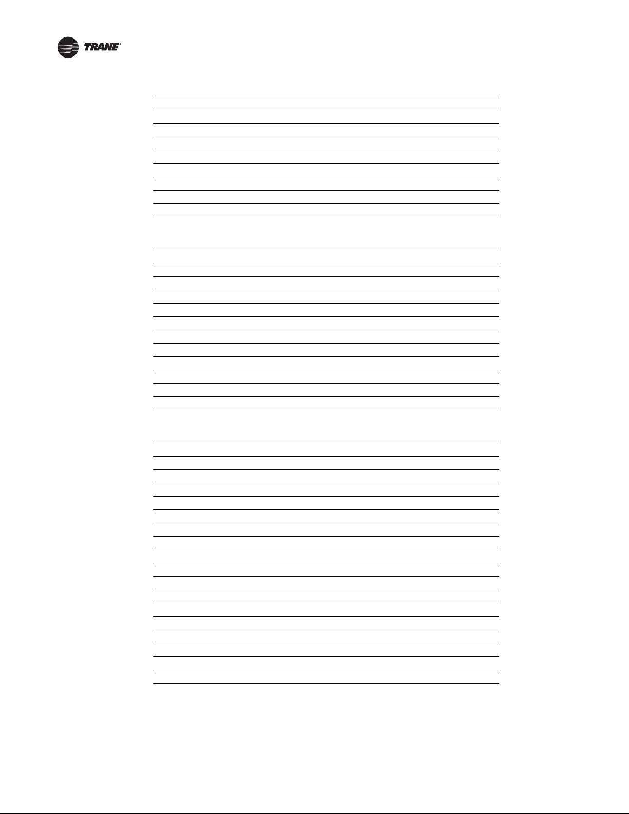
Table 3. Menu P2
20–28 These menu items are not settings Not settings
29(A) Compressor A Starts
29(B) Compressor B Starts
29(C) Compressor C Starts
29(D) Compressor D Starts
2A(A) Compressor A Hours
2A(B) Compressor B Hours
2A(C) Compressor C Hours
2A(D) Compressor D Hours
Table 4. Menu P3
30 External Chilled Water Setpoint d/E
31 External Current Limit Setpoint d/E
32 Ice Machine Control d/E
33 Active Ice Termination Setpoint Not a setting
34 Front Panel Ice Termination Setpoint
35 Return Reset d/E
36 Zone Reset d/E
37 Outdoor Reset d/E
38 Reset Ratio Setpoint
39 Start Reset Setpoint
3A Maximum Reset Setpoint
3b External Circuit Lockout d/E
Table 5. Menu P4
40 Leaving Water Temperature Cutout Setpoint
41 Low Refrigerant Temperature Cutout Setpoint
42 Condenser Limit Setpoint
43 Balanced Compressor Starts and Hours (Lead/Lag) d/E
44 SI Display Units d/E
45 Unit Line Voltage
46 Under/Over Voltage Protection d/E
47 Phase Imbalance Protection d/E
48 Phase Reversal Protection d/E
49 Superheat Setpoint
4A(1) EXV Control Response Setpoint – Circuit 1
4A(2) EXV Control Response Setpoint – Circuit 2
4b Leaving Water Temperature Control Response Setpoint
4C ICS Address
4d(1) Fan Control Deadband Bias – Circuit 1
4d(2) Fan Control Deadband Bias – Circuit 2
4E Programmable Relay Setup
4F Restart Inhibit Timer
4 RTAA-SVN06A-EN
Page 5
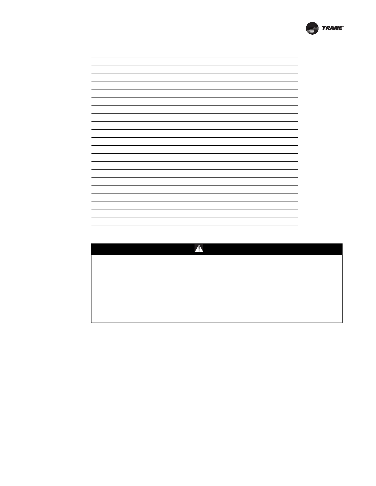
Table 6. Menu P5
50 Number of Compressors
51(A) Compressor A Tons
51(B) Compressor B Tons
51(C) Compressor C Tons
51(D) Compressor D Tons
52 Low Water Temperature EXV Gain Compensation d/E
53 Fan Control d/E
54(1) Number of Fans on Circuit 1
54(2) Number of Fans on Circuit 2
55 Reduced Inrush Startin g d/E
56(A) Compressor A Current Overload Setting
56(B) Compressor B Current Overload Setting
56(C) Compressor C Current Overload Setting
56(D) Compressor D Current Overload Setting
57 GP Compressor Unit Disabled
58 Low Ambient – Half Air Flow Fan d/E
59 Low Ambient Two Speed Motors d/E
5A Night Noise Setback d/E
5b(1) Number of EXV’s on Circuit 1
5b(2) Number of EXV’s on Circuit 2
5C(1) Future Option
5C(2) Future Option
WARNING
Hazardous Voltage w/Capacitors!
Disconnect all electric power, including remote disconnects and discharge all motor start/run
capacitors before servicing. Follow proper lockout/tagout procedures to ensure the power
cannot be inadvertently energized. For variable frequency drives or other energy storing
components provided by Trane or others, refer to the appropriate manufacturer’s literature for
allowable waiting periods for discharge of capacitors. Verify with an appropriate voltmeter that
all capacitors have discharged. Failure to disconnect power and discharge capacitors before
servicing could result in death or serious injury.
For additional information regarding the safe discharge of capacitors, see PROD-SVB06A-EN
3. Disconnect and lockout the power to the chiller.
a. Open the unit disconnect switch that feeds power to the chiller.
b. Install lockout/tagout lock(s).
4. Cut the hole for the new CLD in
a. Remove the existing clear Plexiglas® window from the control panel door.
b. If necessary, remove the control panel door from the chiller.
c. Measure and mark 4.75 in. from the middle hole on top of the existing cutout to just outside
the right and left edges.
d. Measure and mark 1 in. from top edge of existing hole.
e. Measure and mark 11 in. down from the mark made in the previous step.
f. Trace square on door as shown in Figure 1, p. 6.
g. Cut along the traced lines.
h. Deburr the edges of the new hole.
the control panel door.
RTAA-SVN06A-EN 5
Page 6
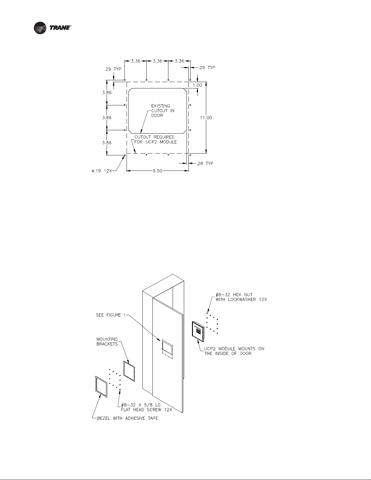
Figure 1. Existing cutout and modifications required
5. Install the CLD2 into the control panel door.
a. Using the new CLD as your template. Hold up the new CLD to the hole and make marks
where holes should be drilled.
b. Drill holes.
c. Starting at the top, attach brackets from the outside of the door in such a way that the door
panel is sandwiched between the CLD on the inside and mounting brackets on the outside
of the door panel as shown in Figure 2. The screw head should be flush with the bracket.
d. Tighten the nuts so that the gasket on the CLD is properly compressed.
e. Remove the tape backing from the plastic bezel and apply it to the outside of the door
opening so it covers the mounting brackets.
Figure 2. New CLD assembly
6 RTAA-SVN06A-EN
Page 7
6. Replace the 1U1 module.
a. If required, mark the wires connected to TB1, TB2, TB3, TB4, and TB5.
b. Remove all wires and connectors from the 1U1 module.
c. Loosen but do not remove the two lower 1U1 mounting screws.
d. Remove the two upper 1U1 mounting screws. If star washers exist on any of the screws, be
careful not to lose them.
e. Remove the 1U1 from the control panel.
f. Install the new 1U1 into the control panel reusing the same screws.
g. Replace the two upper 1U1 mounting screws.
h. Tighten the two lower 1U1 mounting screws.
i. Re-connect wiring to the 1U1. There are differences between TB4 on the old and new 1U1.
Refer to Tabl e 7 when reconnecting wiring to that terminal block.
Table 7. Old-to-new wiring terminal positions on CPM
Terminal 130-400T RTAA 1U1 New RTAA 1U1
TB4-1 ALARM (COMMON) ALARM (COMMON)
TB4-2
TB4-3
TB4-4
TB4-5
TB4-6 COMPRESSOR RUNNING (NORMALLY CLOSED)
TB4-7
TB4-8
TB4-9 EVAPORATOR PUMP (NORMALLY OPEN)
ALARM (NORMALLY OPEN) ALARM (NORMALLY OPEN)
ALARM (NORMALLY CLOSED) ALARM (NORMALLY CLOSED)
COMPRESSOR RUNNING (COMMON) COMPRESSOR RUNNING (COMMON)
COMPRESSOR RUNNING (NORMALLY OPEN) COMPRESSOR RUNNING (NORMALLY OPEN)
MAXIMUM CAPACITY (COMMON)
MAXIMUM CAPACITY (NORMALLY COMMON) MAXIMUM CAPACITY (NORMALLY OPEN)
MAXIMUM CAPACITY (NORMALLY OPEN) EVAPORATOR PUMP (COMMON)
7. Install the 24 Vac transformer.
• Install
the 120/24 Vac transformer in the bottom part of the control panel to the left of 1TB3.
Install the transformer so the primary connections face 1TB3.
8. Install additional wiring.
a. Connect the 24 Vac transformer primary (120 Vac side) wires to 1TB3-1 and 1TB3-2.
b. Connect the 24 Vac transformer secondary to CLD terminals J2-1 and J2-2.
c. Connect the IPC communications wires.
Note: IPC communications is a daisy-chain communications system that is connected to
the J1 connectors on all of the modules in the RTAA control system except for the
CLD.
i. Inspect all of the J1 connectors on the upper left-hand side of each silver control module
and find two open terminals on the IPC communications bus.
ii. When you find two open terminals, remove the white cover from the back of the orange
plug and use a small screwdriver to push 18 AWG wires into the knives on the connector
until they cut through the wire insulation and hold the conductors securely.
iii. Re-install the white plug cover.
Note: If there are no open J1 terminals, you can splice into the IPC communications link
using butt splices or wire nuts. Connect the other end of the IPC communications
wires to J1-1 and J1-2 on the new CLD module.
RTAA-SVN06A-EN 7
Page 8
9. Remove lockout lock and restore power to the chiller.
10. Configure the chiller.
a. Use the settings re
RTAA-SVX01A-EN (Installation, Operation, and Maintenance: Series R® Air-Cooled Rotary
Liquid Chillers) to help you enter settings into the new CLD.
b. Variable Speed Fans should be set to DISABLE for both circuits.
11. Re-start the chiller by
Starts and Hours
Note: The compressor starts and hours recorded in Step 2, p. 3 cannot be transferred into the new
control system. Therefore, it is recommended that you record these numbers for all
compressors. All counters will start from zero in the new CLD control system.
Chilled Water Pump Control
The new control system you’re installing has an added feature. It has a normally open contact
output that can be used to control the evaporator water pump. Refer to Table 7, p. 7 for the
connection points on the new 1U1 module. Chilled Water Pump can be set to ON or AUTO in the
Operator Settings menu. If this setting is ON, the pump output will remain energized any time
the control system is powered. If set to AUTO, the pump output will be energized whenever the
chiller is put into the Auto mode and will de-energize from 1 to 30 minutes (the default is
10 minutes) after the chiller leaves the Auto mode. The 1- to 30-minute timer can be configured in
the Chilled Water Pump Off Delay setting.
corded in Step 2, p. 3 to configure the new CLD. Refer to p. 72 of
pressing the green Auto button on the keypad.
Optional Remote Display Panel
If there is a remote display panel connected to your RTAA chiller, the following settings in your CLD
will need to be made:
ICS Address: 32
Setpoint Source: Tracer
A new operating code may be displayed on the remote coded panel that is not listed on the black
decal on the front of your remote display. The new operating mode is 300 Stopped By Remote
Display. This mode will be displayed as Stopped by Tracer at the chiller front panel.
Trane and the Trane logo are trademarks or registered trademarks of Trane in the United States and other countries. All trademarks referenced in this document are
the trademarks of their respective owners.
Plexiglas is a registered trademark of Arkema France Corporation.
Trane optimizes the performance of homes and buildings around the world. A business of Ingersoll Rand, the
leader in creating and sustaining safe, comfortable and energy efficient environments, Trane offers a broad
portfolio of advanced controls and HVAC systems, comprehensive building services, and parts. For more
information, visit www.Trane.com.
Trane has a policy of continuous product and product data improvement and reserves the right to change design and specifications without notice.
© 2012 Trane All rights reserved
RTAA-SVN06A-EN 27 Jan 2012
New
We are committed to using environmentally
conscious print practices that reduce waste.
 Loading...