

Page 1
Commercial Self-Contained
Deluxe Self-Contained Units
3 –15 Ton Water-Cooled and
Air-Cooled Air Conditioners
Remote Air-Cooled Condensers
December 2001
PKG-PRC010-EN
Page 2
Introduction
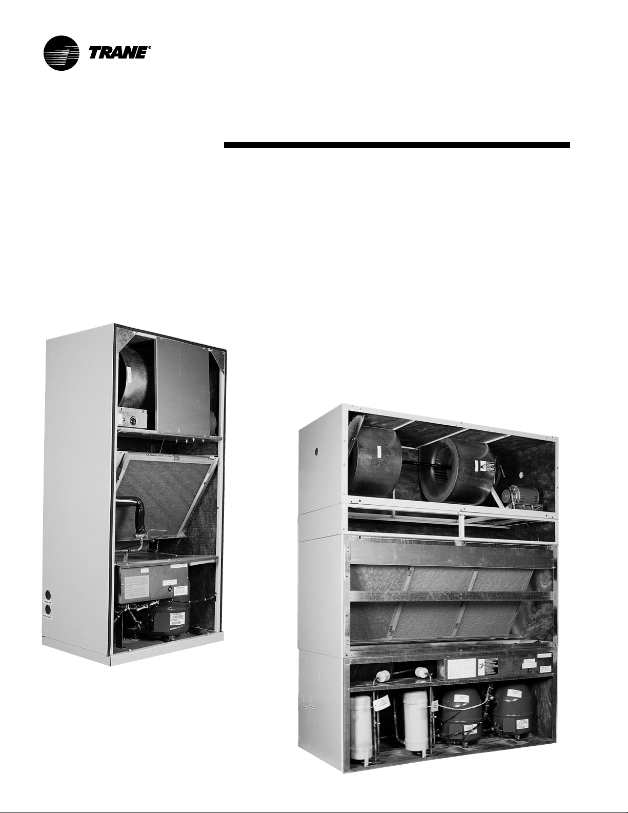
Deluxe Self-Contained Units —
Commercial and Industrial Quality Built into Each Unit
Deluxe self-contained units are single packaged units designed for lowcost installation in the conditioned space or equipment room.
Features include:
• Water-cooled or air-cooled
• Vertical or horizontal fan discharge options, ducted or free return
• Return air options include front or rear
• Easy-to-connect piping and power from either side of unit
• Fully assembled and factory-tested
• Optional accessories:
• plenums
• cupronickel water-cooled condensers
• hot water or steam coils
Industrial options with protective coatings are available to help increase
resistance to acids, mild alkalides, solvents, inorganic salts, and water:
PKG-PRC010-EN©2001American Standard Inc.
Page 3
Contents
Introduction
Features and Benefits
Application Considerations
Selection Procedure
Model Number Description
General Data
Performance Data
Airside Pressure Drop
Fan Data
Waterside Pressure Drop
Correction Factors/Heat of Rejection
Water-Cooled Unit Performance
Air-Cooled Unit Performance
Heating Coil Performance
Electrical Data
2
4
6
7
8
11
13
13
14
18
19
20
25
30
33
Dimensions and Weights
Mechanical Specifications
34
46
3PKG-PRC010-EN
Page 4
Features and Benefits
Deluxe Self-Contained air conditioners,
available in 3–15 tons, are single package
units designed for low cost installation in
the conditioned space or equipment
room. Durable construction, strict quality
control, and demanding factory testing
ensure reliability from start-up through
years of operation.
All units are shipped fully factory assembled and tested, thereby reducing
field labor, installation time, and costs.
They can also be easily converted from
vertical to horizontal discharge arrangements to match most building configurations. Discharge can be either free or
ducted. Power and water connections can
be made from either side of the unit
adding to the unit flexibility.
Available Unit Configurations
3, 5, and 7.5-Ton Units
Standard Features
• 3 through 15-ton industrial/commerical
self-contained units
• Water-cooled or air-cooled condensing
applications
• Single point power connection
• Single point water connection on watercooled units
• Both water and power connections can
be made from either side of the unit
• Front or rear return air openings
• Vertical and horizontal discharge
arrangements
• UL listing on standard unit
• All compressors are protected with
internal motor winding temperature
cutouts
• All compressors have crankcase
heaters as standard
• Variable pitch sheaves allow for field
adjustment of airflow
• High pressure cutout switches on all
units
• Low pressure cutout switches on all
units
• High pressure relief device on watercooled units
Optional Features
• Hydronic heating coils
• Horizontal discharge plenums
• Water regulating valves for condensing
pressure control on water-cooled units
• Protective coating for unit and evaporator coil
• CuproNickel condensers
• Permanent filters
• Unit or remote mounted thermostats
• Low ambient control operation on aircooled condenser
• Oversized fan motor and drive kits
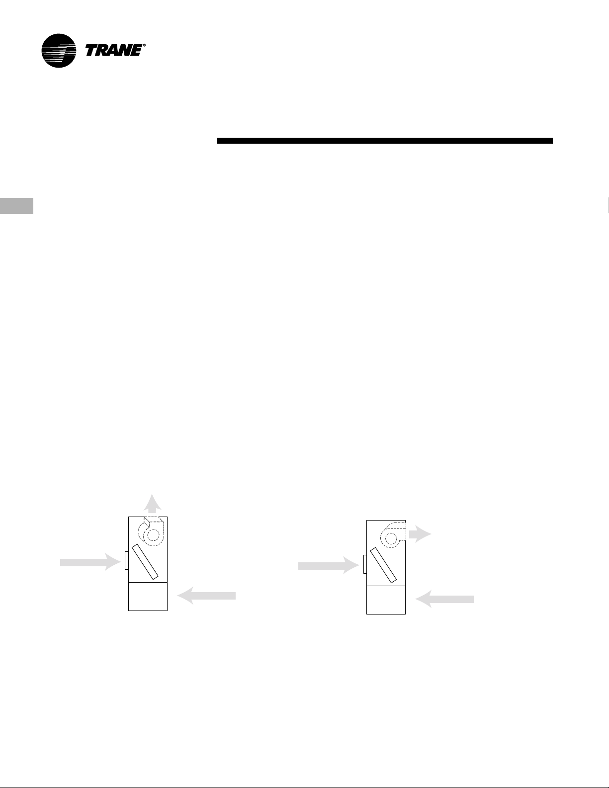
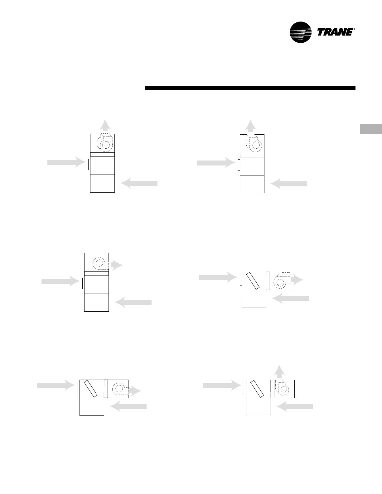
Front Return
standard
Rear Return
field convertible
Figure FB-1. Deluxe Self-Contained 3, 5, & 7.5-Ton Unit
With Vertical Discharge, As Shipped
4
field convertible
fan discharge
Front Return
standard
Figure FB-2. Deluxe Self-Contained 3, 5, & 7.5-Ton Unit
With Horizontal Discharge, Field Converted
Rear Return
field convertible
PKG-PRC010-EN
Page 5
Available Unit Configurations
10 and 15-Ton Units
Features and
Benefits
field convertible
clockwise vertical discharge
Front Return
field convertible
Rear Return
standard
Figure FB-3. Deluxe Self-Contained 10 & 15-Ton Unit With
Counter-Clockwise Vertical Discharge, As Shipped
field convertible
counter-clockwise
Front Return
field convertible
horizontal discharge
Rear Return
standard
Figure FB-5. Deluxe Self-Contained 10 & 15-Ton Unit With
Counter-Clockwise Horizontal Discharge, Field Converted
Front Return
field convertible
Rear Return
standard
Figure FB-4. Deluxe Self-Contained 10 & 15-Ton Unit With
Clockwise Vertical Discharge, Field Converted
Front Return
field convertible
Rear Return
standard
field convertible
clockwise horizontal
discharge
Figure FB-6. Deluxe Self-Contained 10 & 15-Ton Unit With
Clockwise Horizontal Discharge, Field Converted
Front Return
field convertible
Rear Return
standard
field convertible
counter-clockwise
horizontal discharge
Figure FB-7. Deluxe Self-Contained 10 & 15-Ton Unit With
Counter-Clockwise Horizontal Discharge, Field Converted
field convertible
clockwise vertical
Front Return
field convertible
discharge
Rear Return
standard
Figure FB-8. Deluxe Self-Contained 10 & 15-Ton Unit With
Clockwise Vertical Discharge, Field Converted
5PKG-PRC010-EN
Page 6

Application
CCRA Air-Cooled
CCRA Unit Location
Unobstructed condenser airflow is
essential to maintain capacity and
operating efficiency. When determining
unit placement, give careful consideration to assure sufficient airflow across
the condenser coils. Avoid these two
detrimental conditions: warm air recirculation and coil starvation.
Both warm air recirculation and coil
starvation cause reductions in unit
efficiency and capacity because of the
higher head pressure associated with
them. In more severe cases, nuisance
unit shutdowns will result from excessive
head pressures.
Considerations
Clearance
Ensure vertical condenser air discharge is
unobstructed. While it is difficult to
predict the degree of warm air recirculation, a unit installed with a ceiling or
other obstruction above it will experience
a capacity reduction that will reduce the
maximum ambient operation. Nuisance
high head pressure tripouts may also
occur.
The coil inlet must also be unobstructed.
A unit installed closer than the minimum
recommended distance to a wall or other
vertical riser will experience a combination of coil starvation and warm air
recirculation. This may result in unit
capacity and efficiency reductions, as
well as possible excessive head pressures. Reference the service clearance
section on page 45 for recommended
lateral distances.
Condenser
Ambient Limitations
Standard ambient control allows operation down to 45°F (7.2°C) with cycling of
condenser fans. Units with the low
ambient option are capable of starting
and operating in ambient temperatures
down to 0°F (-17.8°C). Optional low
ambient units use a condenser fan
damper arrangement that controls
condenser capacity by modulating
damper airflow in response to saturated
condenser temperature.
Maximum cataloged ambient temperature operation of a standard condenser is
115°F (46.1°C). Operation at design
ambient above 115°F can result in
excessive head pressures. For operation
above 115°F, contact the local Trane sales
office.
6
PKG-PRC010-EN
Page 7

Selection Procedure
Selection Procedure
The selection of a deluxe self-contained
unit can be accomplished in three easy
steps.
Step 1 - Load
Determine the load requirements for
heating and cooling (include outside air)
using Trane’s load estimate program or
any standard method.
Step 2 - Unit Type
Self-contained air conditioners are
available in either water-cooled or
remote air-cooled models to match
individual needs.
Step 3 - Select the Unit
The conditions under which the unit must
operate and the design load will give the
final selection.
Selection Example
Design conditions for a water-cooled unit:
Entering air temperature = 80/67°F
Total gross capacity required = 64,400
Btu/h
Entering water temperature = 85°F
Leaving water temperature = 95°F
Airflow = 2,400 cfm at 0.5-inch duct static
pressure
Unit Selection
Tentatively select a 5-ton unit: Model
SCWB-B50. Refer to Table PD-10 on
page 21 to obtain gross total and sensible
unit capacities, gpm, and leaving water
temperature at nominal conditions:
Total capacity = 66 MBh
Sensible capacity = 45 MBh
Water flow rate = 20 gpm
Leaving water temperature = 93.1°F
Since the design cfm is greater than the
nominal cfm, the capacities and condenser water delta T must be adjusted to
reflect the higher cfm.
Self-Contained
Design cfm = 2,400
Nominal cfm = 2,000 + 20% of nominal
cfm
Refer to Table PD-6 on page19 to obtain
the capacity correction factors for +20%
of nominal cfm:
Cooling capacity multiplier = 1.03
Sensible capacity multiplier = 1.05
Multiply the capacities by the correction
factors:
66 MBh x 1.03 = 68.0 MBh
45 MBh x 1.05 = 47.3 MBh
The SCWB-B50 meets the total and
sensible design requirements.
Subtract the entering water temperature
from the leaving water temperature to
determine condenser water delta T of
8.1°F. Multiply the delta T by the cooling
capacity correction factor of 1.03 to
obtain the new delta T of 8.3°F and add
this to the entering water temperature to
obtain the actual leaving water temperature of 93.3°F. The leaving condenser
water temperature is within the design
delta T of 10°F.
Refer the fan data Table PD-1 on page 14
to determine approximate brake horsepower and fan rpm:
Fan brake horsepower = 1.09 bhp
Fan rpm = 934 rpm
Determine net capacities by subtracting
fan motor heat from gross capacities:
2.8 X 1.09 bhp = 3.1 MBh
Net total capacity = 67.8 MBh - 3.1 MBh
= 64.7 MBh
Net sensible capacity = 48.7MBh - 3.1
MBh = 45.6 MBh
Refer to the Trane psychrometric chart to
determine leaving air temperatures.
7PKG-PRC010-EN
Page 8
Selection
Model Number
Procedure
Description
Deluxe Self-Contained Model Number Description
Following is a complete description of the deluxe self-contained model number. Each digit in the model number has a corresponding code that identifies specific unit options.
S C W B B30 4 4 * * 1 0 1 1 A 0 1 2 A A 0 0 F A 0 1 0 0 U
1 2 3 4 567 8 9 1011 12 13 14 15 16 17 18 19 20 21 22 23 24 25 26 27 28 29 30
Digit 1 - Unit Model
S = Self Contained
Digit 2 - Unit Type
C = Commercial
I = Industrial
Digit 3 - Condenser Medium
W = Water-Cooled
R = Remote Air-Cooled
Digit 4 - Development Sequence
B = Development Series
Digit 5, 6, 7 - Unit Nominal Capacity
B30 = 3 Tons
B50 = 5 Tons
B75 = 7.5 Tons
C10 = 10 Tons
C15 = 15 Tons
Digit 8 - Unit Voltage
4 = 460 Volt/60 Hz/3 ph
5 = 575 Volt/60 Hz/3 ph
6 = 208-230 Volt/60 Hz/3 ph
Digit 9 - Air Volume/Temp Control
4 = CV - Zone Temp Cool Only
5 = CV - Zone Temp Heat/Cool
0 = CV - With No Temp Control
Digit 10, 11 - Design Sequence
** = Factory Assigned
Digit 12 - Unit Construction
1 = Vertical Discharge with Front Return
3 = Vertical Discharge with Rear Return
Digit 13 - Plenum Type
0 = Without Plenum
Digit 14 - Motor Type
1 = Standard Motor
Digit 15 - Fan Drive Kits
1 = Standard Drive Kit
Digit 16 - Filter Type
A = 1” Construction Throwaway
Digit 17 - Heating Type
0 = Without Factory Installed Heat
Digit 18 - Unit Finish
1 = Paint - Deluxe Beige
2 = Protective Coating
3 = Protective Coating with Finish Coat
Digit 19 - Unit Connection
2 = Terminal Block
Digit 20 - Coil Option
A = Non-coated Aluminum Evaporator
C = Corrosion Protective Coated
Aluminum Evaporator
Digit 21 - Drain Pan Type
A = Galvanized Standard
Digit 22 - Economizer Type
0 = Without Unit Economizer
Digit 23 - Waterside Valves
0 = Without Water Valve(s)
Digit 24 - Unit Insulation
F = Matte-Faced Fiberglass Insulation
Digit 25 - Condenser Type
A = Standard Condenser
E = 90/10 CuNi Condenser
0 = Without Condenser
Digit 26 - Compressor Service Valves
0 = Without Service Valves
Digit 27 - Temperature Control
0 = Remote Thermostat Interface
1 = Standard Unit Mounted
Thermostat
3 = Remote Thermostat, 0H/2C
4 = Remote T’stat, 2H/2C (Manual)
5 = Remote T’stat, 2H/2C (Auto)
6 = Remote Prog. T’stat, 1H/2C
7 = Remote Prog. T’stat. 2H/2C
Digit 28 - System Control
0 = Without System Control
Digit 29 - Control Options
0 = No System Control Options
Digit 30 - Agency Listing
B = UL and CSA Agency Approval
T = CSA Agency Approval
U = UL Agency Approval
0 = No Agency Approval
8
PKG-PRC010-EN
Page 9

Selection
Model Number
Procedure
Description
Self-Contained Accessory Model Number Description
A 1 0 1 0 0 A 0 B 0 0 2 0 2 A 1 0 0
1 2 3 4 5 6 7 8 9 10 11 12 13 14 15 16 17 18
Digit 1 - Discharge Plenum
A = 3 Ton Standard Plenum
B = 3 Ton Protective Coated Plenum
C = 5 Ton Standard Plenum
D = 5 Ton Protective Coated Plenum
E = 7.5 Ton Standard Plenum
F = 7.5 Ton Protective Coated Plenum
G = 10 Ton Standard Plenum
H = 10 Ton Protective Coated Plenum
I = 15 Ton Standard Plenum
J = 15 Ton Protective Coated Plenum
0 = None
Digit 2 - Permanent Filters
1 = 3 Ton (1) 20 x 25 x 1
2 = 5 Ton (2) 16 x 25 x 1
3 = 7.5 Ton (4) 15 x 20 x 1
4 = 10 Ton (3) 20 x 25 x 2
5 = 15 Ton (8) 15 x 20 x 2
0 = None
Digit 3 - Front Return Air Grille
A = 10 Ton Front Return Air Grille
B = 10 Ton Protective Coated Front Rtn
Air Grille
C = 15 Ton Front Return Air Grille
D = 15 Ton Protective Coated Front Rtn
Air Grille
0 = None
Digit 4 - Rubber-In-Shear Isolators
1 = 3 Ton Isolators
2 = 5 Ton Isolators
3 = 7.5 Ton Isolators
4 = 10 Ton Standard Configuration
Isolators
5 = 10 Ton Horz. Inverted “L” Isolators
(Air-Cooled Units Only)
6 = 10 Ton Horz. Inverted “L” Isolators
(Water-Cooled Units Only)
7 = 15 Ton Standard Configuration
Isolators
8 = 15 Ton Horz. Inverted “L” Isolators
(Air and Water-Cooled Units)
0 = None
Digit 5 - Steel Spring Isolators
A = 3 Ton Isolators
B = 5 Ton Isolators
C = 7.5 Ton Isolators
D = 10 Ton Standard Configuration
Isolators (Air-Cooled Units Only)
E = 10 Ton Standard Configuration
Isolators (Water-Cooled Units Only)
F = 10 Ton Horz. Inverted “L” Isolators
(Air and Water-Cooled Units)
G = 15 Ton Standard Configuration
Isolators
H = 15 Ton Horz. Inverted “L” Isolators
(Air and Water Cooled Units)
0 = None
Digit 6 - Unit Mounted Thermostat
1 = 10 & 15 Ton 2 Cool Thermostat
2 = 3, 5, & 7.5 Ton 2 Cool Thermostat
0 = None
Digit 7 - Remote Mounted Thermostat
A = 3, 5, & 7.5 Ton 0H/2C (Auto)
B = 10 & 15 Ton 2H/2C (Manual)
C = 10 & 15 Ton 2H/2C (Auto)
0 = None
Digit 8 - Programmable Night Setback
Thermostat
1 = 3, 5, & 7.5 Ton 1H/2C
2 = 10 & 15 Ton 2H/2C
0 = None
Digit 9 - Fan Motor Kits (Includes Drives)
A = 3 Ton,
B = 3 Ton,
C = 5 Ton, 1 HP, 208-230 Volt
D = 5 Ton, 1 HP, 460 Volt
E = 5 Ton, 1F = 5 Ton, 1-1/2 HP, 460 Volt
G = 7.5 Ton, 10 = None
Digit 10 - Oversize Fan Motor Kits
1 = 10 Ton, 3 HP, 208-230 & 460 Volt
2 = 15 Ton, 5 HP, 208-230 & 460 Volt
0 = None
Digit 11 - Accessory Drive Kits
A = 10 Ton, Underspeed Drive Kit
B = 15 Ton, Underspeed Drive Kit
C = 10 & 15 Ton, Overspeed Drive Kit
D = 15 Ton, Extra Overspeed Drive Kit
0 = None
Digit 12 - Hot Water Heating Coil
1=3 Ton
2 = 3 Ton with Corrosion Protection
3=5 Ton
4 = 5 Ton with Corrosion Protection
5 = 7.5 Ton
3
/4 HP, 208-230 Volt
3
/4 HP, 460 Volt
1
/2 HP, 208-230 Volt
1
/2 HP, 208-230 & 460 Volt
6 = 7.5 Ton with Corrosion Protection
7 = 10 Ton
8 = 10 Ton with Corrosion Protection
9 = 15 Ton
A = 15 Ton with Corrosion Protection
0 = None
Digit 13 - Steam Heating Coil
A=3 Ton
B = 3 Ton with Corrosion Protection
C=5 Ton
D = 5 Ton with Corrosion Protection
E = 7.5 Ton
F = 7.5 Ton with Corrosion Protection
G = 10 Ton
H = 10 Ton with Corrosion Protecton
I = 15 Ton
J = 15 Ton with Corrosion Protection
0 = None
Digit 14 - 90/10 Cupronickel Condensers
1 = 3 Ton CuNi Condenser
2 = 3 Ton CuNi Protective Coated
Condenser
3 = 5 Ton CuNi Condenser
4 = 5 Ton CuNi Protective Coated
Condenser
5 = 7.5 Ton CuNi Condenser
6 = 7.5 Ton CuNi Protective Coated
Condenser
7 = 10 Ton CuNi Condenser
8 = 10 Ton CuNi Protective Coated
Condenser
9 = 15 Ton CuNi Condenser
A = 15 Ton CuNi Protective Coated
Condenser
Digit 15 - Water Regulating Valve Kit
A = 3 Ton Water Reg. Valve Kit
B = 5 & 7.5 Ton Water Reg. Valve Kit
C = 10 & 15 Ton Water Reg. Valve Kit
Digit 16 - Anti-Recycle Timer
1 = Anti-Recycle Timer
0 = None
Digit 17 - Time Delay Relay
1 = 10 & 15 Ton Time Delay Relay
0 = None
Digit 18 - Low Ambient Damper
A = 3 & 5 Ton Low Ambient Damper
B = 7.5 Ton Low Ambient Damper
C = 10 Ton Low Ambient Damper
D = 15 Ton Low Ambient Damper
0 = None
9PKG-PRC010-EN
Page 10
Selection
Model Number
Procedure
Description
Remote Air-Cooled Condenser
C C R A B50 2 0 * * 4 A U
1 2 3 4 567 8 9 10 11 12 13 14
Digit 1 - Unit Model
C = Condenser
Digit 2 - Unit Type
C = Commercial
I = Industrial
Digit 3 - Condenser Medium
R = Remote Air-cooled
Digit 4 - Development Sequence
A=A
Digit 5, 6, 7 - Nominal Capacity
B30 = 3 Tons
B50 = 5 Tons
B75 = 7.5 Tons
C10 = 10 Tons
C15 = 15 Tons
Digit 8 - Unit Voltage
1 = 208-230 Volt/60 Hz/1 ph
2 = 460 Volt/60 Hz/1 ph
8 = 575 Volt/60 Hz/1 ph
Digit 9 - Low Ambient
C = Low Ambient Damper(s)
0 = Without Low Ambient Control
Digit 10, 11 - Design Sequence
** = Factory Assigned
Digit 12 - Unit Finish
2 = Protective Coating
3 = Protective Coating with
Finish Coat
4 = Unpainted Unit
Digit 13 - Coil Options
A = Non-Coated Aluminum
C = Protective Coated Aluminum
Digit 14 - Agency Listing
B = UL and CSA Agency Approval
T = CSA Agency Approval
U = UL Agency Approval
0 = No Agency Approval
10
PKG-PRC010-EN
Page 11
General Data
Self-Contained
Table GD-1. SCRB/SIRB/SCWB/SIWB Deluxe Self-Contained General Data
Unit Size 357.51015
Compressor Data
Quantity 11122
Nominal Ton/Comp 3 5 7.5 5 7.5
Circuits 11122
Evaporator Coil Data
Rows 33333
Sq. Ft. 2.68 5.08 7.08 9.82 16.04
Sq. m (.25) (.47) (.66) (.91) (1.49)
FPF 144 144 144 144 144
Condenser Data (Water-Cooled Only)
Quantity 12222
Minimum gpm 5 8 11 15 23
Minimum liters / sec. (.32) (.50) (.69) (.95) (1.45)
Maximum gpm 12 2 0 30 40 50
Maximum liters / sec. (.76) (1.26) (1.89) (2.52) (3.15)
Minimum EWT w/out valve, °F 65 65 65 65 65
Minimum EWT with valve, °F 35 35 35 35 35
Evaporator Fan Data
Quantity 11122
Size Dia. x width - inches 10 x 10 12 x 12 15 x 15 12 x 9 12 x 9
Size Dia. x width - mm (254x254) (305x305) (381x381) (305x229) (305x229)
Standard HP
Oversized HP Available
Minimum Design cfm 960 1600 2400 3200 4800
Minimum Design liter / sec. (453) (755) (1133) (1510) (2265)
1
/
2
3
/
4
Maximum Design cfm 1440 2400 3600 4800 7200
Maximum Design liter / sec. (680) (1133) (1699) (2265) (3398)
General Data
EER (SXRB) 10.0 10.0 10.3 10.3 9.7
EER (SXWB) 12.1 12.1 11.5 11.5 12.0
Refrigerant Charge - lbs. R-22 per Circuit
Total Charge (SXWB) 6.0 11.0 10.0 8.0/8.0 7.5/7.5
Refrigerant Charge - kg R-22
Total Charge (SXWB) (2.18) (3.63) (3.99) (5.35) (7.26)
Capacity Steps - % 100/0 100/0 100/0 100/50/0 100/50/0
Filter Data
Quantity 12438
Size (inches) 20x25x1 16x25x1 15x20x1 20x25x1 15x20x1
Size (mm) (508x635x25) (406x635x25) (381x508x25) (508x635x25) (381x508x25)
Heating Coil Data
Steam Coil
Coil Type SDS SDS SDS NS NS
Rows 11111
Size (inches) 12 x 23
Size (mm) (305 x 591) (381 x 711) (457 x 811) (305 x 1346) (305 x 1854)
1
/
FPF 180 180 180 144 144
Hot Water Coil
Coil Type WC WC WC WC WC
Rows 22222
Size (inches) 15 x 20
Size (mm) (381 x 519) (381 x 635) (381 x 737) (742 x 1388) (508 x 1921
7
/
FPF 108 108 108 108 108
Notes:
1. All units operate with R-22. Water-cooled units ship with full operating charge. Air-cooled units ship with a dry nitrogen
holding charge.
2. Hot water coils do not have turbulators. See Capacity DataTables PD-19 and PD-20 for coil capacities.
3. Steam Coil capacities are shown in Table PD-21.
4. Maximum cfm limits are set to prevent moisture carryover on the evaporator coil.
5. Minimum cfm limits are set to ensure stable thermal expansion valve operation at low load conditions.
6. SCWB/SIWB/SCRB/SIRB 3, 5, 7.5, and 10 ton units are rated at ARI Standard 210/240-1994. SCWB/SIWB/SCRB/SIRB 15-ton
units are rated at ARI Standard 340/360-2000.
7. SCRB/SIRB 3 and 5-ton units are rated as SEER.
3
/
4
1, 1-1/
2
15 x 28 18 x 31 15/
4
15 x 25 15 x 29 5/820 x 54 5/820 x 75 5/
16
123
1-1/
2
35
12 x 53 12 x 73
16
8
11PKG-PRC010-EN
Page 12
Air-Cooled
General Data
Condenser
Table GD-2. CCRA/CIRA Remote Air-Cooled Condenser General Data
Unit Size 357.51015
Gross Heat Rejection (MBh) 59 102 116 207 232
Gross Heat Rejection (kW) (17.3) (29.9) (34.0) (60.7) (68.0)
Condenser Fan Data
Number/Type 1/Prop 1/Prop 2/Prop 2/Prop 4/Prop
Size (inches) 18” 22” 22” 22” 20”
Size (mm) (457) (559) (559) (559) (508)
Fan Drive Direct Direct Direct Direct Direct
No. of Motors/HP ea. 1/0.33 1/0.75 2/0.75 2/0.75 4/0.75
Nominal cfm
Nominal (liters / sec)
Condenser Coil Data
Circuit 1 Size (in.) 36 x 48 36 x 48 72 x 96 36 x 48 36 x 48
Circuit 1 Size (mm) (914 x 1219) (914 x 1219) (1828x 2438) (914 x 1219) (914 x 1219)
Circuit 2 No./Size (in.) n/a n/a n/a 36 x 48 36 x 48
Circuit 2 No./Size (mm) (914 x 1219) (914 x 1219)
Face Area (sq. Ft.) 12.0 12.0 24.0 24.0 24.0
Face Area (sq.m) (1.1) (1.1) (2.2) (2.2) (2.2)
Rows/fpf 2/144 3/144 3/144 3/144 3/144
Ambient Temp. Operating Range
Standard Ambient (°F) 40 - 115 40 - 115 40 - 115 40 - 115 40 - 115
Standard Ambient (°C) (4.4 - 46.1) (4.4 - 46.1) (4.4 - 46.1) (4.4 - 46.1) (4.4 - 46.1)
Low Ambient Option (°F) 0 - 115 0 - 115 0 - 115 0 - 115 0 - 115
Low Ambient Option (°C) (-17.8 - 46.1) (-17.8 - 46.1) (-17.8 - 46.1) (-17.8 - 46.1) (-17.8 - 46.1)
Notes:
1. Gross heat rejection is at a 30°F (-1.1°C) ITD (initial temperature difference) between condensing temperature and
ambient air entering condenser (includes the effect of subcooling).
12
PKG-PRC010-EN
Page 13
Performance
Heating
Data
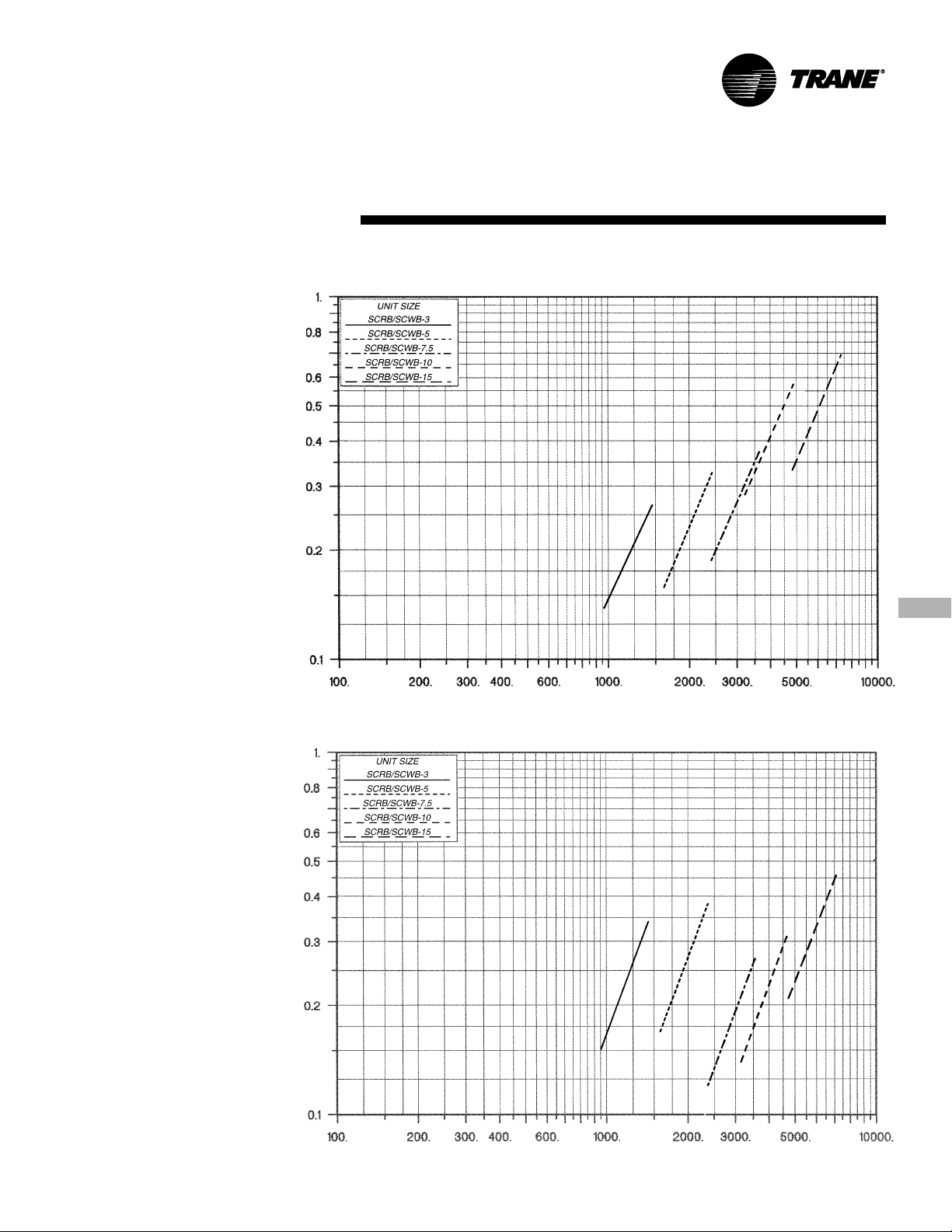
Chart PD-1. Heating Coil Airside Pressure Drop
Pressure Drop, in. wc.
Coils
Chart PD-2. Plenum Airside Pressure Drop
Pressure Drop, in. wc.
Unit Airflow, cfm
Unit Airflow, cfm
13PKG-PRC010-EN
Page 14
Performance
Data
Fan Data
Table PD-1. Fan Performance Data, 0.10 to 0.80 esp
External Static Pressure
Unit 0.10 0.20 0.30 0.40 0.50 0.60 0.70 0.80
Size cfm rpm bhp rpm bhp rpm bhp rpm bhp rpm bhp rpm bhp rpm bhp rpm bhp
3-Ton 960 616 0.14 682 0.17 750 0.21 816 0.25 880 0.30 940 0.35 993 0.40 1044 0.45
5-Ton 1600 557 0.29 611 0.32 660 0.37 708 0.42 760 0.49 817 0.57 869 0.66 919 0.75
7.5-Ton 2400 517 0.42 556 0.50 598 0.59 638 0.68 677 0.78 710 0.87 745 0.98 782 1.09
10-Ton 3200 589 0.53 641 0.60 684 0.66 730 0.74 775 0.82 813 0.88 853 0.96 891 1.05
15-Ton 4800 521 0.92 554 0.97 589 1.08 624 1.17 656 1.28 689 1.39 721 1.50 752 1.60
Note:
Non-standard drive selection
Oversize motor required
Oversize motor required and non-standard drive selection
1080 677 0.19 735 0.22 796 0.26 856 0.36 915 0.35 972 0.40 1027 0.46 1077 0.52
1200 739 0.25 792 0.28 845 0.33 901 0.37 955 0.42 1007 0.47 1059 0.53 1110 0.59
1320 802 0.32 852 0.35 898 0.40 949 0.45 999 0.50 1048 0.55 1196 0.61 1143 0.67
1440 866 0.41 913 0.44 955 0.49 1000 0.54 1046 0.60 1092 0.65 1137 0.71
1800 612 0.40 664 0.43 709 0.47 751 0.54 793 0.67 839 0.67 888 0.75 937 0.85
2000 668 0.55 717 0.57 759 0.61 799 0.67 837 0.74 875 0.84 915 0.88 958 0.97
2200 724 0.72 771 0.75 812 0.77 849 0.83 884 0.90 919 0.98 953 1.05 989 1.13
2400 781 0.93 826 0.96 865 0.99 900 1.02 934 1.09 966 1.17 998 1.26 1029 1.34
2700 570 0.57 607 0.66 643 0.75 680 0.86 715 0.96 751 1.08 781 1.18 811 1.28
3000 625 0.76 661 0.87 691 0.96 725 1.07 758 1.18 789 1.29 822 1.42
3300 681 1.00 715 1.11 742 1.21 771 1.31 803 1.44
3600 739 1.28 767 1.39 796 1.50
3600 649 0.72 698 0.81 739 0.88 777 0.95 819 1.04 860 1.14 894 1.21 929 1.29
4000 709 0.97 755 1.06 796 1.15 832 1.23 865 1.31 903 1.41 942 1.52 974 1.60
4400 771 1.26 814 1.37 853 1.47 888 1.56 920 1.64 950 1.73 984 1.84 1020 1.97
4800 833 1.61 874 1.74 911 1.85 945 1.95 976 2.05 1005 2.14 1033 2.24 1062 2.35
5400 578 1.29 608 1.34 637 1.43 669 1.56 700 1.66 729 1.77 758 1.90 787 2.02
6000 636 1.76 663 1.80 689 1.87 717 2.00 745 2.14 773 2.26 799 2.38 825 2.51
6600 694 2.34 719 2.38 743 2.43 767 2.53 792 2.68 819 2.84 844 2.98 868 3.10
7200 752 3.03 776 3.07 798 3.12 820 3.20 842 3.32 866 3.49 890 3.67 913 3.82
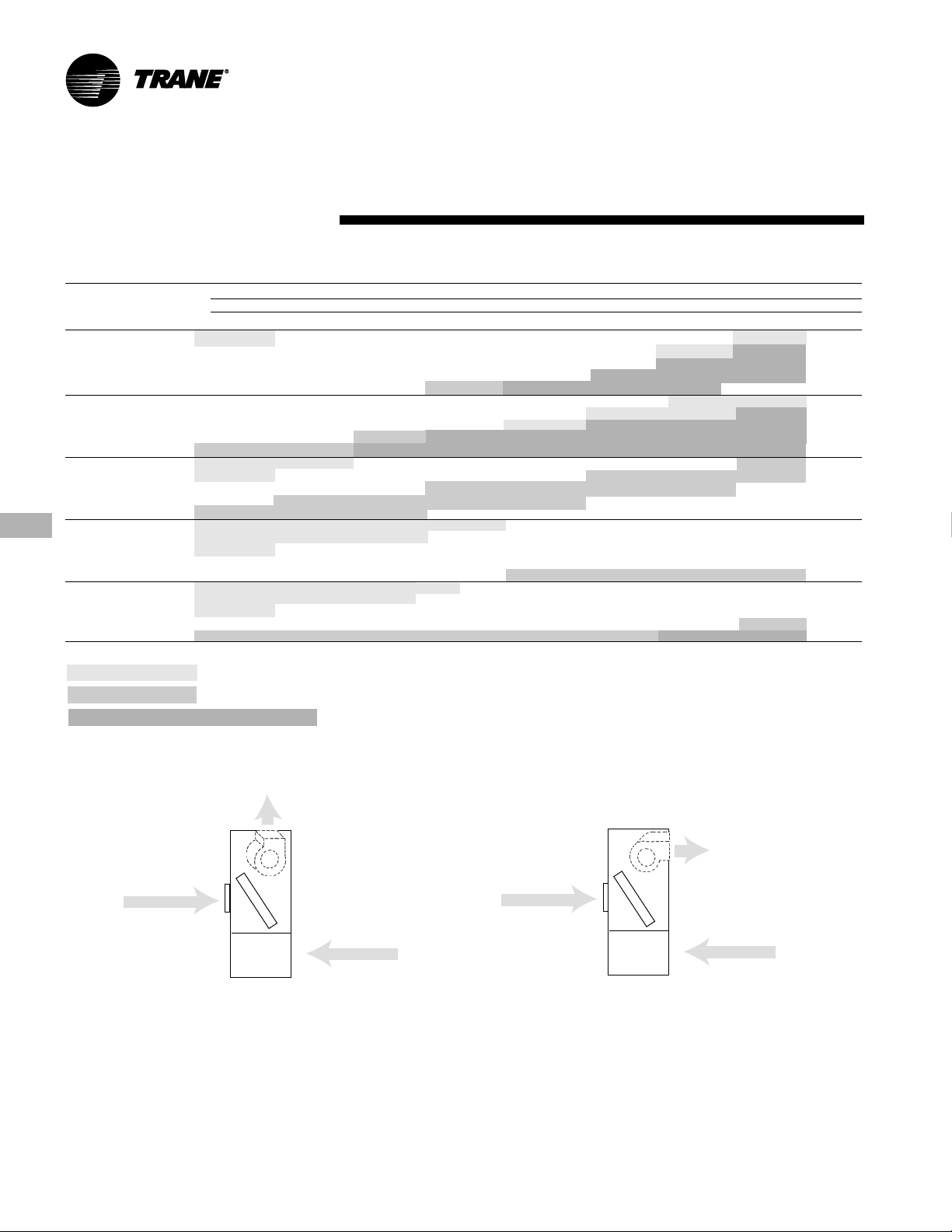
Use Tables PD-1 and PD-2 with these unit configurations:
3, 5, & 7.5-Ton Units
Front Return
standard
Rear Return
field convertible
14
Front Return
standard
field convertible
fan discharge
Rear Return
field convertible
PKG-PRC010-EN
Page 15
Performance
Data
Fan Data
Table PD-2. Fan Performance Data, 0.90 to 2.50 esp
External Static Pressure
Unit 0.90 1.00 1.10 1.25 1.50 1.75 2.00 2.25 2.50
Size cfm rpm bhp rpm bhp rpm bhp rpm bhp rpm bhp rpm bhp rpm bhp rpm bhp rpm bhp
3-Ton 960 1092 0.50 1138 0.55 1183 0.60 1248 0.69
5-Ton 1600 968 0.84 1017 0.94 1064 1.04 1134 1.19
7.5-Ton 2400 817 1.21 850 1.33 880 1.44
10-Ton 3200 928 1.14 967 1.23 1007 1.33 1063 1.48 1150 1.76 1234 2.11 1314 2.47 1391 2.86
15-Ton 4800 782 1.71 810 1.82 836 1.92 873 2.08 935 2.36 997 2.70 1062 3.09 1125 3.52 1186 3.98
Note:
Non-standard drive selection
Oversize motor required
Oversize motor required and non-standard drive selection
1080 1124 0.57 1169 0.63 1212 0.68
1200 1158 0.66 1202 0.72
1320 1190 0.74
1440
1800 984 0.95 1029 1.05 1072 1.16 1137 1.31
2000 1003 1.07 1046 1.18 1088 1.29 1149 1.46
2200 1027 1.21 1067 1.32 1108 1.44
2400 1062 1.42
2700 843 1.41
3000
3300
3600
3600 965 1.38 998 1.48 1031 1.58 1082 1.74 1170 2.01 1248 2.30 1324 2.66
4000 1005 1.68 1037 1.78 1069 1.89 1114 2.05 1189 2.33 1269 2.64 1342 2.94
4400 1052 2.07 1080 2.16 1108 2.25 1152 2.41 1222 2.71
4800 1096 2.48 1128 2.61 1156 2.72 1194 2.86
5400 815 2.14 843 2.26 869 2.39 907 2.57 964 2.86 1019 3.17 1074 3.51 1130 3.89 1187 4.34
6000 851 2.66 877 2.78 903 2.92 940 3.12 998 3.46 1051 3.79 1101 4.13 1150 4.47 1199 4.86
6600 892 3.24 916 3.39 939 3.55 974 3.77 1032 4.14 1085 4.51 1134 4.88
7200 936 3.95 945 4.10 979 4.25 1012 4.51 1065 4.92
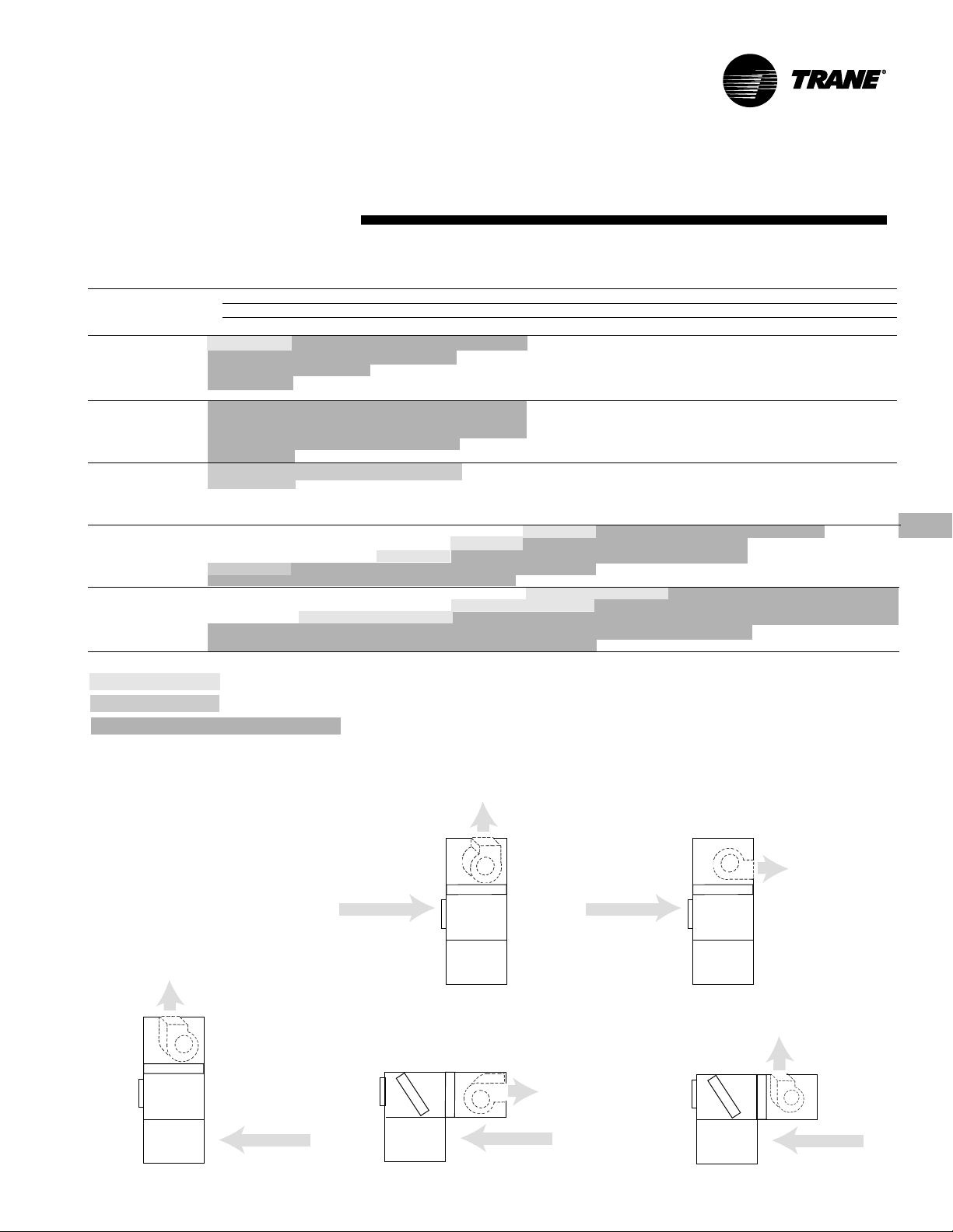
Use Tables PD-1 and PD-2 with these unit configurations:
10 & 15-Ton Units
Front Return
field convertible
field convertible
clockwise vertical discharge
Rear Return
standard
Rear Return
standard
Front Return
field convertible
field convertible
clockwise horizontal
discharge
field convertible
counter-clockwise
horizontal discharge
field convertible
clockwise vertical
discharge
Rear Return
standard
15PKG-PRC010-EN
Page 16

Performance
Data
Fan Data
Table PD-3. Fan Performance Data, 0.10 to 0.80 esp
Unit 0.10 0.20 0.30 0.40 0.50 0.60 0.70 0.80
Size cfm rpm bhp rpm bhp rpm bhp rpm bhp rpm bhp rpm bhp rpm bhp rpm bhp
10-Ton 3200 460 0.45 520 0.49 572 0.56 623 0.63 670 0.70 716 0.78 762 0.86 805 0.95
15-Ton 4800 478 0.77 516 0.85 555 0.95 597 1.05 634 1.17 668 1.26 700 1.34 733 1.45
Note:
Non-standard drive selection
Oversize motor required
Oversize motor required and non-standard drive selection
3600 501 0.62 558 0.67 608 0.73 653 0.80 698 0.89 741 0.97 782 1.05 823 1.14
4000 544 0.84 597 0.89 644 0.95 698 1.03 728 1.11 768 1.20 808 1.29 845 1.38
4400 586 1.10 637 1.16 682 1.22 724 1.29 763 1.38 799 1.47 836 1.57 872 1.67
4800 632 1.41 679 1.48 721 1.54 761 1.61 799 1.70 834 1.79 867 1.89 900 2.00
5400 529 1.08 562 1.15 596 1.25 632 1.37 670 1.48 703 1.62 734 1.74 763 1.82
6000 582 1.47 611 1.53 641 1.64 672 1.76 705 1.88 739 2.01 770 2.16 798 2.31
6600 634 1.94 660 2.00 688 2.10 716 2.22 744 2.36 773 2.50 804 2.63 834 2.79
7200 688 2.51 711 2.57 736 2.66 761 2.78 787 2.92 813 3.07 840 3.22 868 3.37
External Static Pressure
Use Tables PD-3 and PD-4 with these unit configurations:
10 & 15-Ton Units
Front Return
field convertible
Front Return
field convertible
field convertible
clockwise vertical
discharge
field convertible
clockwise horizontal
discharge
field convertible
counter-clockwise
horizontal discharge
Rear Return
Front Return
field convertible
Rear Return
standard
Front Return
field convertible
Rear Return
standard
field convertible
counter-clockwise
horizontal discharge
field convertible
clockwise vertical discharge
standard
16
PKG-PRC010-EN
Page 17

Performance
Data
Table PD-4. Fan Performance Data, 0.90 to 2.50 esp
Unit 0.90 1.00 1.10 1.25 1.50 1.75 2.00 2.25 2.50
Size cfm rpm bhp rpm bhp rpm bhp rpm bhp rpm bhp rpm bhp rpm bhp rpm bhp rpm bhp
10-Ton 3200 846 1.03 887 1.13 925 1.24 980 1.40 1064 1.67 1141 1.95 1215 2.28 1287 2.59 1356 2.94
15-Ton 4800 765 1.58 796 1.70 825 1.81 869 1.98 939 2.31 1007 2.70 1071 3.14 1132 3.60 1189 4.07
Note:
Non-standard drive selection
Oversize motor required
Oversize motor required and non-standard drive selection
3600 863 1.24 900 1.33 937 1.43 992 1.59 1077 1.89 1154 2.19 1225 2.50 1293 2.83
4000 882 1.48 918 1.58 955 1.69 1006 1.84 1088 2.13 1166 2.45 1238 2.78
4400 907 1.77 940 1.87 973 1.97 1024 2.15 1102 2.44 1178 2.74
4800 934 2.11 967 2.21 998 2.33 1044 2.50 1121 2.80
5400 792 1.92 821 2.05 849 2.19 891 2.39 956 2.71 1020 3.05 1081 3.45 1141 3.91 1198 4.44
6000 825 2.42 851 2.51 877 2.62 916 2.84 979 3.22 1039 3.57 1097 3.93 1153 4.84 1208 4.80
6600 861 2.96 886 3.11 910 3.23 945 3.39 1008 3.75 1063 4.18 1118 4.57 1171 4.96
7200 896 3.53 922 3.72 946 3.90 980 4.12 1034 4.41 1088 4.80
External Static Pressure
Fan Data
17PKG-PRC010-EN
Page 18

Performance
Waterside
Data
Chart PD-3. Waterside Pressure Drop
Pressure Drop, ft water
Pressure Drop
Note: Chart PD-3 includes factory piping and condenser. If adding a water regulating valve, add valve WPD to the
value in Chart PD-3. 10 and 15 ton units use two water regulating valves. Therefore, divide the gpm and WPD by 2 to
determine values through each valve.
Table PD-5. Water Regulating Valve Pressure Drop, ft of water
9 101112131415161718192021222324252627282930
4.6 6.0 6.9 8.1 9.9 12.0 16.6 18.4 21.0 23.1 28.9 34.6 36.9 40.4 43.4 46.2 53.1 56.6 61.9 64.0 69.3 76.2
Note: Table PD-5 is based on wide open water valve.
gpm
Condenser Flowrate, gpm
18
PKG-PRC010-EN
Page 19

Performance
Data
Table PD-6. Cfm Capacity Correction Table – Cooling
Cfm Compared Cooling Sensible
To Rated Capacity Capacity
Quanitity Multiplier Multiplier
-20% 0.96 0.95
DX Cooling Std 1.00 1.00
* If, after applying these multipliers, the SHR is greater than 1.0, use 1.0
Table PD-7. Cfm Capacity Correction Table – Heating
Hydronic Heating Std 1.00
-10% 0.98 0.98
+10% 1.02 1.02*
+20% 1.03 1.05*
Cfm Compared Heating
To Rated Capacity
Quanitity Multiplier
-20% 0.89
-10% 0.94
+10% 1.06
+20% 1.12
Table PD-8. Altitude Correction Factors
Altitude 2000 4000 6000 8000 10,000
Cooling Capacity Multiplier 0.98 0.95 0.92 0.89 0.86
Chart PD-4. CCRA/CIRA Gross Heat of Rejection
Heat of Rejection, MBh
Initial Temperature Difference (ITD)
19PKG-PRC010-EN
Page 20

Performance
Water-Cooled
Data
3 Ton
Table PD-9. SCWB/SIWB 3 Gross Cooling Capacity - 1200 cfm
65°F 75°F 85°F 95°F 100°F
EDB EWB Flow Tot Sen LWT Tot Sen LWT Tot Sen LWT Tot Sen LWT Tot Sen LWT
F F gpm MBh MBh F k W MBh MBh F k W MBh MBh F k W MBh MBh F k W MBh MBh F k W
70 62 5 34 21 83.5 2.1 33 20 93.1 2.3 31 19 102.6 2.4 30 19 112.1 2.5 29 18 116.7 2.6
75 62 5 34 25 83.5 2.1 33 24 93.1 2.2 31 23 102.6 2.4 30 23 112.0 2.5 29 22 116.7 2.6
80 62 5 34 29 83.5 2.1 33 28 93.1 2.2 31 28 102.6 2.4 29 27 112.0 2.5 29 26 116.6 2.6
85 62 5 34 33 83.5 2.1 33 32 93.1 2.3 31 31 102.7 2.4 30 30 112.3 2.5 29 29 117.0 2.6
Notes: 1. All capacities shown are gross and have not considered indoor fan heat. 2. TOT = total gross cooling capacity. 3. SEN = sensible heat capacity.
6 35 21 79.0 2.0 33 20 88.7 2.2 32 20 98.3 2.3 30 19 107.9 2.5 29 18 112.6 2.5
9 36 21 74.4 1.9 34 21 84.2 2.1 32 20 93.9 2.2 31 19 103.7 2.4 30 19 108.5 2.5
12 36 22 72.0 1.8 34 21 81.9 2.0 33 20 91.7 2.2 31 19 101.5 2.4 30 19 106.4 2.4
67 5 38 17 85.1 2.2 36 16 94.7 2.3 34 15 104.2 2.5 33 14 113.6 2.7 32 14 118.2 2.7
6 38 17 80.2 2.0 37 16 89.9 2.2 35 15 99.5 2.4 33 15 109.1 2.6 32 14 113.8 2.7
9 39 17 75.2 1.9 38 16 85.0 2.1 36 16 94.8 2.3 34 15 104.5 2.5 33 15 109.3 2.6
12 39 17 72.7 1.9 38 17 82.5 2.1 36 16 92.3 2.3 34 15 102.2 2.4 33 15 106.9 2.5
6 35 25 79.0 2.0 33 24 88.7 2.2 32 24 98.3 2.3 30 23 107.9 2.5 29 23 112.6 2.5
9 36 26 74.3 1.9 34 25 84.2 2.1 32 24 93.9 2.2 31 23 103.7 2.4 30 23 108.5 2.5
12 36 26 72.0 1.8 34 25 81.9 2.0 33 24 91.7 2.2 31 23 101.5 2.4 30 23 106.3 2.4
67 5 38 21 85.1 2.2 36 20 94.7 2.3 34 19 104.2 2.5 33 18 113.6 2.7 32 18 118.2 2.7
6 38 21 80.2 2.0 37 20 89.9 2.2 35 20 99.5 2.4 33 19 109.1 2.6 32 18 113.8 2.7
9 39 21 75.2 1.9 37 21 85.0 2.1 36 20 94.8 2.3 34 19 104.5 2.5 33 19 109.2 2.6
12 39 21 72.7 1.9 38 21 82.5 2.1 36 20 92.3 2.3 34 19 102.1 2.4 33 19 106.9 2.5
72 5 41 16 86.8 2.3 40 16 96.4 2.4 38 15 105.8 2.6 36 14 115.2 2.8 35 14 119.8 2.9
6 42 17 81.5 2.1 40 16 91.2 2.3 39 15 100.8 2.5 37 14 110.3 2.7 36 14 115.0 2.8
9 43 17 76.1 2.0 41 16 85.9 2.2 39 16 95.6 2.4 37 15 105.3 2.6 37 14 110.1 2.7
12 43 17 73.3 1.9 42 16 83.2 2.1 40 16 93.0 2.3 38 15 102.8 2.5 37 15 107.6 2.6
6 35 29 78.9 2.0 33 29 88.6 2.2 32 28 98.3 2.3 30 27 107.9 2.5 29 27 112.6 2.5
9 35 30 74.3 1.9 34 29 84.2 2.1 32 28 93.9 2.2 31 27 103.7 2.4 30 27 108.4 2.5
12 36 30 72.0 1.8 34 29 81.9 2.0 33 28 91.7 2.2 31 27 101.5 2.3 30 27 106.3 2.4
67 5 38 25 85.1 2.2 36 24 94.6 2.3 34 23 104.1 2.5 33 23 113.6 2.7 32 22 118.2 2.7
6 38 25 80.2 2.0 37 24 89.8 2.2 35 24 99.5 2.4 33 23 109.1 2.6 32 22 113.8 2.7
9 39 25 75.2 1.9 37 25 85.0 2.1 36 24 94.7 2.3 34 23 104.5 2.5 33 23 109.2 2.6
12 39 26 72.7 1.9 38 25 82.5 2.1 36 24 92.3 2.3 34 23 102.1 2.4 33 23 106.9 2.5
72 5 41 20 86.8 2.3 39 20 96.3 2.4 38 19 105.8 2.6 36 18 115.2 2.8 35 18 119.8 2.9
6 42 21 81.5 2.1 40 20 91.2 2.3 39 19 100.8 2.5 37 19 110.3 2.7 36 18 115.0 2.8
9 43 21 76.1 2.0 41 20 85.8 2.2 39 20 95.6 2.4 37 19 105.3 2.6 36 19 110.1 2.7
12 43 21 73.3 1.9 42 21 83.2 2.1 40 20 93.0 2.3 38 19 102.8 2.5 37 19 107.6 2.6
6 35 33 78.9 2.0 33 33 88.7 2.2 32 32 98.3 2.3 30 30 108.0 2.5 30 30 112.8 2.6
9 35 34 74.3 1.9 34 33 84.2 2.1 32 32 93.9 2.2 31 31 103.7 2.4 30 30 108.6 2.5
12 36 34 72.0 1.8 34 33 81.9 2.0 33 32 91.7 2.2 31 31 101.6 2.4 31 31 106.4 2.4
67 5 38 29 85.1 2.2 36 28 94.9 2.3 34 27 104.1 2.5 32 27 113.6 2.7 32 26 118.2 2.7
6 38 29 80.2 2.0 37 28 89.8 2.2 35 28 99.5 2.4 33 27 109.1 2.6 32 27 113.7 2.7
9 39 29 75.2 1.9 37 29 85.0 2.1 36 28 94.7 2.3 34 27 104.5 2.5 33 27 109.2 2.6
12 39 30 72.6 1.9 38 29 82.5 2.1 36 28 92.3 2.3 34 27 102.1 2.4 33 27 106.9 2.5
72 5 41 24 86.8 2.3 39 24 96.3 2.4 38 23 105.8 2.6 36 22 115.2 2.8 35 22 119.8 2.9
6 42 25 81.5 2.1 40 24 91.1 2.3 38 23 100.7 2.5 37 23 110.3 2.7 36 22 115.0 2.8
9 43 25 76.1 2.0 41 24 85.8 2.2 39 24 95.6 2.4 37 23 105.3 2.6 36 23 110.1 2.7
12 43 25 73.3 1.9 41 25 83.2 2.1 40 24 93.0 2.3 38 23 102.8 2.5 37 23 107.6 2.6
Entering Water Temperature
20
PKG-PRC010-EN
Page 21

Performance
Water-Cooled
Data
5 Ton
Table PD-10. SCWB/SIWB 5 Gross Cooling Capacity - 2000 cfm
65°F 75°F 85°F 95°F 105°F
EDB EWB Flow Tot Sen LWT Tot Sen LWT Tot Sen LWT Tot Sen LWT Tot Sen LWT
F F gpm MBh MBh F k W MBh MBh F k W MBh MBh F k W MBh MBh F k W MBh MBh F k W
70 62 8 63 38 85.3 3.8 60 37 95.0 4.2 58 36 104.6 4.5 55 35 114.2 4.9 52 33 123.7 5.2
75 62 8 63 46 85.3 3.8 60 45 95.0 4.2 58 44 104.6 4.5 55 43 114.2 4.9 52 42 123.7 5.2
80 62 8 63 55 85.3 3.8 60 53 95.0 4.2 58 52 104.6 4.5 55 51 114.2 4.8 52 50 123.7 5.2
85 62 8 63 62 85.4 3.9 61 61 95.1 4.2 58 58 104.8 4.6 56 56 114.6 4.9 54 54 124.3 5.3
Notes: 1. All capacities shown are gross and have not considered indoor fan heat. 2. TOT = total gross cooling capacity. 3. SEN = sensible heat capacity.
10 64 39 80.3 3.6 61 38 90.1 4.0 59 37 99.8 4.3 56 35 109.5 4.7 53 34 119.2 5.0
15 65 40 75.3 3.4 63 38 85.1 3.8 60 37 94.9 4.1 57 36 104.8 4.5 55 35 114.5 4.8
20 65 40 72.7 3.3 63 39 82.6 3.7 61 37 92.5 4.0 58 36 102.3 4.4 55 35 112.2 4.7
67 8 68 30 86.9 4.0 66 29 96.6 4.3 63 28 106.2 4.7 60 26 115.7 5.1 57 25 125.2 5.4
10 70 30 81.6 3.7 67 29 91.3 4.1 64 28 101.0 4.5 61 27 110.7 4.8 58 26 120.3 5.2
15 71 31 76.1 3.5 68 30 85.9 3.9 66 29 95.8 4.3 63 28 105.5 4.6 60 26 115.3 5.0
20 - - - - 69 30 83.2 3.7 66 29 93.1 4.1 64 28 102.9 4.5 60 27 112.8 4.9
10 64 47 80.3 3.6 61 46 90.1 4.0 59 45 99.8 4.3 56 43 109.5 4.7 53 42 119.2 5.0
15 65 48 75.3 3.4 63 46 85.1 3.8 60 45 94.9 4.1 57 44 104.7 4.5 55 43 114.5 4.8
20 65 48 72.7 3.3 63 47 82.6 3.7 61 46 92.5 4.0 58 44 102.3 4.4 55 43 112.2 4.7
67 8 68 38 86.9 4.0 66 37 96.6 4.3 63 36 106.2 4.7 60 34 115.7 5.1 57 33 125.2 5.4
10 70 38 81.5 3.7 67 37 91.3 4.1 64 36 101.0 4.5 61 35 110.7 4.8 58 34 120.3 5.2
15 71 39 76.1 3.5 68 38 85.9 3.9 66 37 95.7 4.3 63 36 105.5 4.6 60 34 115.3 5.0
20 - - - - 69 38 83.2 3.7 66 37 93.1 4.1 63 36 102.9 4.5 60 35 112.8 4.9
72 8 74 29 88.6 4.1 71 28 98.2 4.5 68 27 107.8 4.9 65 26 117.3 5.3 - - - -
10 76 30 82.8 3.8 73 29 92.6 4.2 70 28 102.2 4.6 67 26 111.9 5.0 63 25 121.5 5.4
15 - - - - 74 29 86.8 4.0 72 28 96.6 4.4 68 27 106.4 4.8 65 26 116.1 5.2
20 - - - - 75 30 83.9 3.8 72 29 93.7 4.2 69 27 103.6 4.6 66 26 113.4 5.1
10 64 55 80.3 3.6 61 54 90.1 4.0 59 53 99.8 4.3 56 51 109.5 4.7 53 50 119.2 5.0
15 65 56 75.2 3.4 62 54 85.1 3.8 60 53 94.9 4.1 57 52 104.7 4.5 55 51 114.5 4.8
20 65 56 72.7 3.3 63 55 82.6 3.7 61 54 92.5 4.0 58 52 102.3 4.4 55 51 112.2 4.7
67 8 68 46 86.9 4.0 66 45 96.6 4.3 63 44 106.1 4.7 60 42 115.7 5.1 57 41 125.1 5.4
10 69 46 81.5 3.7 67 45 91.3 4.1 64 44 101.0 4.5 61 43 110.7 4.8 58 42 120.3 5.2
15 71 47 76.1 3.5 68 46 85.9 3.9 66 45 95.7 4.3 63 44 105.5 4.6 60 42 115.3 5.0
20 - - - - 69 46 83.2 3.7 66 45 93.1 4.1 63 44 102.9 4.5 60 43 112.7 4.9
72 8 74 37 88.6 4.1 71 36 98.2 4.5 68 35 107.7 4.9 65 34 117.2 5.3 - - - -
10 76 38 82.8 3.8 73 37 92.5 4.2 70 36 102.2 4.6 67 34 111.9 5.0 63 33 121.5 5.4
15 - - - - 74 37 86.8 4.0 71 36 96.6 4.4 68 35 106.3 4.8 65 34 116.1 5.2
20 - - - - 75 38 83.9 3.8 72 37 93.7 4.2 69 35 103.5 4.6 66 34 113.4 5.1
10 64 63 80.3 3.6 62 61 90.1 4.0 59 59 99.9 4.3 57 57 109.7 4.7 55 55 119.5 5.1
15 65 63 75.3 3.4 63 62 85.1 3.8 60 60 95.0 4.1 58 58 104.9 4.5 56 56 114.7 4.9
20 65 64 72.7 3.3 63 62 82.6 3.7 61 61 92.5 4.0 59 59 102.4 4.4 56 56 112.3 4.8
67 8 68 54 86.9 4.0 65 53 96.5 4.3 63 52 106.1 4.7 60 50 115.7 5.1 57 49 125.1 5.4
10 69 54 81.5 3.7 67 53 91.3 4.1 64 52 101.0 4.5 61 51 110.6 4.8 58 50 120.3 5.2
15 71 55 76.1 3.5 68 54 85.9 3.9 66 53 95.7 4.3 63 52 105.5 4.6 60 50 115.3 5.0
20 - - - - 69 54 83.2 3.7 66 53 93.1 4.1 63 52 102.9 4.5 60 51 112.7 4.9
72 8 74 45 88.6 4.1 71 44 98.2 4.5 68 43 107.7 4.9 65 42 117.2 5.3 - - -
10 75 46 82.8 3.8 73 45 92.5 4.2 70 44 102.2 4.6 67 42 111.8 5.0 63 41 121.4 5.4
15 - - - - 74 45 86.8 4.0 71 44 96.6 4.4 68 43 106.3 4.8 65 42 116.1 5.2
20 - - - - 75 46 83.8 3.8 72 44 93.7 4.2 69 43 103.5 4.6 66 42 113.4 5.0
Entering Water Temperature
21PKG-PRC010-EN
Page 22

Performance
Water-Cooled
Data
7.5 Ton
Table PD-11. SCWB/SIWB 7.5 Gross Cooling Capacity - 3000 cfm
65°F 75°F 85°F 95°F 105°F
EDB EWB Flow Tot Sen LWT Tot Sen LWT Tot Sen LWT Tot Sen LWT Tot Sen LWT
F F gpm MBh MBh F k W MBh MBh F k W MBh MBh F k W MBh MBh F k W MBh MBh F k W
70 62 11 97 59 86.8 6.6 92 57 96.3 7.0 88 54 105.7 7.5 83 52 115.1 7.9 78 50 124.4 8.3
75 62 11 97 71 86.8 6.5 92 68 96.2 7.0 88 66 105.7 7.5 83 64 115.0 7.9 78 62 124.4 8.3
80 62 11 97 83 86.8 6.5 92 80 96.2 7.0 87 78 105.6 7.5 83 76 115.0 7.9 78 73 124.4 8.3
85 62 11 97 94 86.8 6.5 93 92 96.3 7.0 88 88 105.8 7.5 84 84 115.4 8.0 80 80 125.0 8.5
Notes: 1. All capacities shown are gross and have not considered indoor fan heat. 2. TOT = total gross cooling capacity. 3. SEN = sensible heat capacity.
15 99 60 81.1 6.2 94 58 90.7 6.7 90 55 100.3 7.2 85 53 109.9 7.7 80 51 119.4 8.1
23 101 61 75.8 5.9 96 59 85.6 6.4 92 56 95.3 7.0 87 54 105.0 7.4 82 52 114.7 7.9
30 102 61 73.1 5.7 97 59 82.9 6.3 92 57 92.8 6.8 88 54 102.5 7.3 82 52 112.3 7.8
67 11 106 46 88.6 6.9 101 44 98.0 7.4 96 42 107.4 7.9 91 40 116.8 8.3 85 38 126.1 8.8
15 108 47 82.5 6.5 103 45 92.1 7.0 98 43 101.6 7.6 93 41 111.2 8.1 88 39 120.7 8.5
23 - - - - 106 46 86.5 6.7 100 44 96.2 7.3 95 42 105.9 7.8 90 39 115.6 8.3
30 - - - - 107 47 83.6 6.5 102 44 93.4 7.1 96 42 103.2 7.6 91 40 113.0 8.2
15 99 72 81.1 6.2 94 69 90.7 6.7 90 67 100.3 7.2 85 65 109.9 7.7 80 63 119.4 8.1
23 101 73 75.8 5.9 96 70 85.6 6.4 91 68 95.3 7.0 87 66 105.0 7.4 81 63 114.7 7.9
30 102 73 73.1 5.7 97 71 82.9 6.3 92 69 92.8 6.8 87 66 102.5 7.3 82 64 112.3 7.8
67 11 106 58 88.6 6.9 101 56 98.0 7.4 96 54 107.4 7.9 91 52 116.8 8.3 85 49 126.1 8.8
15 108 59 82.4 6.5 103 57 92.1 7.0 98 55 101.6 7.6 93 53 111.2 8.1 88 50 120.6 8.5
23 - - - - 105 58 86.5 6.7 100 56 96.2 7.3 95 54 105.9 7.8 90 51 115.5 8.3
30 - - - - 106 58 83.6 6.5 101 56 93.4 7.1 96 54 103.2 7.6 91 52 113.0 8.2
72 11 115 45 90.5 7.2 110 43 99.9 7.7 104 41 109.3 8.3 99 39 118.6 8.8 - - - -
15 118 46 83.9 6.7 113 44 93.5 7.3 107 42 103.0 7.9 102 40 112.5 8.4 96 38 112.0 9.0
23 - - - - 115 45 87.4 6.9 110 43 97.1 7.5 104 41 106.8 8.1 98 39 116.5 8.7
30 - -- - ---- 1114494.1 7.3 105 42 103.9 7.9 100 39 113.6 8.5
15 99 84 81.1 6.2 94 81 90.7 6.7 90 79 100.3 7.2 85 77 109.9 7.7 80 74 119.4 8.1
23 101 84 75.8 5.9 96 82 85.6 6.4 91 80 95.3 7.0 86 78 105.0 7.4 81 75 114.7 7.9
30 102 85 73.1 5.7 97 83 82.9 6.3 92 80 92.7 6.8 87 78 102.5 7.3 82 76 112.3 7.8
67 11 106 70 88.6 6.8 101 68 98.0 7.4 96 66 107.4 7.9 91 63 116.7 8.3 85 61 126.0 8.8
15 108 71 82.4 6.5 103 69 92.0 7.0 98 67 101.6 7.6 93 64 111.1 8.1 88 62 120.6 8.5
23 - - - - 105 70 86.4 6.7 100 68 96.2 7.3 95 65 105.9 7.8 90 63 115.5 8.3
30 - - - - 106 70 83.6 6.5 101 68 93.4 7.1 96 66 103.2 7.6 91 64 112.9 8.2
72 11 115 57 90.5 7.2 110 55 99.9 7.7 104 53 109.2 8.3 99 51 118.6 8.8 - - - -
15 118 58 83.9 6.7 113 56 93.4 7.3 107 54 103.0 7.9 102 52 112.5 8.4 96 50 112.0 9.0
23 - - - - 115 57 87.4 6.9 110 55 97.1 7.5 104 53 106.8 8.1 98 51 116.4 8.7
30 - -- - ---- 1115694.1 7.3 105 53 103.9 7.9 100 51 113.6 8.5
15 99 95 81.1 6.2 95 93 90.8 6.7 90 90 100.4 7.2 86 86 110.1 7.7 82 82 119.8 8.2
23 101 96 75.8 5.9 96 94 85.6 6.4 92 91 95.3 7.0 87 87 105.1 7.5 83 83 114.9 8.0
30 102 97 73.1 5.7 97 94 82.9 6.3 93 92 92.8 6.8 88 88 102.6 7.3 84 84 112.4 7.9
67 11 105 82 88.5 6.8 101 80 98.0 7.4 96 77 107.4 7.9 90 75 116.7 8.3 85 73 126.0 8.8
15 108 83 82.4 6.5 103 81 92.0 7.0 98 78 101.6 7.6 93 76 111.1 8.1 87 74 120.6 8.5
23 - - - - 105 82 86.4 6.7 100 79 96.2 7.2 95 77 105.9 7.8 90 75 115.5 8.3
30 - - - - 106 82 83.6 6.5 101 80 93.4 7.1 96 78 103.2 7.6 91 75 112.9 8.1
72 11 115 69 90.4 7.2 110 67 99.9 7.7 104 65 109.2 8.3 99 63 118.5 8.8 - - - -
15 118 70 83.8 6.7 112 68 93.4 7.3 107 66 103.0 7.9 102 64 112.5 8.4 96 62 121.9 9.0
23 - - - - 115 69 87.4 6.9 110 67 97.1 7.5 104 65 106.8 8.1 98 62 116.4 8.7
30 - -- - ---- 1116794.1 7.3 105 65 103.9 7.9 99 63 113.6 8.5
Entering Water Temperature
22
PKG-PRC010-EN
Page 23

Performance
Water-Cooled
Data
10 Ton
Table PD-12. SCWB/SIWB 10 Gross Cooling Capacity - 4000 cfm
65°F 75°F 85°F 95°F 105°F
EDB EWB Flow Tot Sen LWT Tot Sen LWT Tot Sen LWT Tot Sen LWT Tot Sen LWT
F F gpm MBh MBh F k W MBh MBh F k W MBh MBh F k W MBh MBh F k W MBh MBh F k W
70 62 15 121 75 84.8 7.8 116 72 94.5 8.5 111 70 104.1 9.2 106 68 113.7 9.8 100 65 123.2 10.5
75 62 15 121 91 84.8 7.8 116 88 94.5 8.5 111 86 104.1 9.2 106 84 113.7 9.8 100 81 123.2 10.5
80 62 15 121 107 84.8 7.8 116 104 94.4 8.5 111 102 104.1 9.2 106 99 113.7 9.8 100 97 123.2 10.5
85 62 15 121 121 84.9 7.8 117 117 94.6 8.5 113 113 104.4 9.2 109 109 114.1 9.9 104 104 123.8 10.7
Notes: 1. All capacities shown are gross and have not considered indoor fan heat. 2. TOT = total gross cooling capacity. 3. SEN = sensible heat capacity.
20 124 76 80.0 7.4 119 74 89.7 8.1 114 71 99.5 8.8 109 69 109.2 9.4 103 66 118.8 10.1
30 126 77 75.1 6.9 122 75 84.9 7.6 117 73 94.8 8.4 112 70 104.6 9.1 106 68 114.3 9.8
40 128 78 72.6 6.6 123 76 82.5 7.4 118 73 92.3 8.1 113 71 102.2 8.9 107 68 112.0 9.6
67 15 132 58 86.3 8.1 126 55 96.0 8.8 121 53 105.6 9.5 115 51 115.1 10.2 109 48 124.6 11.0
20 135 59 81.1 7.6 130 57 90.9 8.3 124 54 100.6 9.1 118 52 110.3 9.8 112 50 119.9 10.5
30 138 60 75.8 7.0 133 58 85.7 7.8 128 56 95.5 8.6 122 53 105.3 9.3 116 51 115.1 10.1
40 139 61 73.2 6.7 135 59 83.1 7.5 129 57 92.9 8.3 124 54 102.8 9.1 118 52 112.6 9.9
20 124 92 80.0 7.4 119 90 89.7 8.1 114 87 99.5 8.8 109 85 109.2 9.4 103 82 118.8 10.1
30 126 93 75.0 6.9 122 91 84.9 7.6 117 89 94.7 8.3 111 86 104.5 9.1 106 84 114.3 9.8
40 128 94 72.6 6.6 123 92 82.5 7.4 118 89 92.3 8.1 113 87 102.2 8.9 107 84 112.0 9.6
67 15 131 74 86.3 8.1 126 71 96.0 8.8 121 69 105.6 9.5 115 67 115.1 10.2 109 64 124.6 10.9
20 135 75 81.1 7.6 130 73 90.9 8.3 124 70 100.6 9.1 118 68 110.3 9.8 112 65 119.9 10.5
30 138 76 75.8 7.0 133 74 85.7 7.8 127 72 95.5 8.6 122 69 105.3 9.3 116 67 115.1 10.1
40 139 77 73.2 6.7 134 75 83.1 7.5 129 73 92.9 8.3 123 70 102.8 9.1 117 68 112.6 9.9
72 15 142 56 87.9 8.4 137 54 97.5 9.1 131 52 107.1 9.9 125 49 116.6 10.7 - - - -
20 146 58 82.4 7.8 141 56 92.1 8.6 135 53 101.8 9.4 129 51 111.4 10.1 122 48 121.0 11.0
30 150 59 76.7 7.2 144 57 86.5 8.0 139 55 96.3 8.8 133 52 106.1 9.6 126 50 115.8 10.4
40 152 60 73.8 6.8 146 58 83.7 7.7 141 56 93.5 8.5 135 53 103.4 9.3 128 51 113.2 10.2
20 124 108 79.9 7.4 119 106 89.7 8.1 114 103 99.5 8.8 108 101 109.2 9.4 103 98 118.8 10.1
30 126 109 75.0 6.9 122 107 84.9 7.6 117 105 94.7 8.3 111 102 104.5 9.1 106 99 114.3 9.8
40 128 110 72.6 6.6 123 108 82.4 7.4 118 105 92.3 8.1 113 103 102.2 8.8 107 100 112.0 9.6
67 15 131 89 86.3 8.1 126 87 95.9 8.8 121 85 105.5 9.5 115 82 115.1 10.2 109 80 124.6 10.9
20 134 91 81.1 7.6 129 89 90.9 8.3 124 86 100.6 9.1 118 84 110.3 9.8 112 81 119.9 10.5
30 138 92 75.8 7.0 133 90 85.7 7.8 127 88 95.5 8.6 122 85 105.3 9.3 116 83 115.1 10.1
40 139 93 73.2 6.7 134 91 83.0 7.5 129 88 92.9 8.3 123 86 102.8 9.1 117 83 112.6 9.9
72 15 142 72 87.9 8.3 137 70 97.5 9.1 131 68 107.1 9.9 125 65 116.6 10.6 - - - -
20 146 73 82.3 7.8 141 71 92.1 8.6 135 69 101.8 9.4 129 67 111.4 10.1 122 64 121.0 10.9
30 150 75 76.7 7.2 144 73 86.5 8.0 139 71 96.3 8.8 132 68 106.1 9.6 126 66 115.8 10.4
40 151 76 73.8 6.8 146 74 83.7 7.7 141 71 93.5 8.5 134 69 103.4 9.3 128 67 113.2 10.2
20 124 123 80.0 7.4 120 120 89.8 8.1 116 116 99.6 8.8 111 111 109.5 9.5 106 106 119.2 10.3
30 127 125 75.1 6.9 122 122 84.9 7.6 118 118 94.8 8.4 114 114 104.7 9.1 109 109 114.6 9.9
40 128 125 72.6 6.6 124 123 82.5 7.4 119 119 92.4 8.1 115 115 102.3 8.9 110 110 112.2 9.6
67 15 131 105 86.3 8.1 126 103 95.9 8.8 121 101 105.5 9.5 115 98 115.1 10.2 108 96 124.6 10.9
20 134 107 81.7 7.6 129 104 90.9 8.3 124 102 100.6 9.1 118 100 110.2 9.8 112 97 119.9 10.5
30 137 108 75.8 7.0 133 106 85.7 7.8 127 103 95.5 8.6 122 101 105.3 9.3 115 98 115.1 10.1
40 139 109 73.1 6.7 134 106 83.0 7.5 129 104 92.9 8.3 123 102 102.8 9.1 117 99 112.6 9.9
72 15 142 88 87.9 8.3 137 86 97.5 9.1 131 83 107.1 9.9 124 81 116.6 10.6 - - - -
20 146 89 82.3 7.8 140 87 92.1 8.6 135 85 101.8 9.4 128 83 111.4 10.1 122 80 121.0 10.9
30 149 91 76.7 7.2 144 89 86.5 8.0 138 86 96.3 8.8 132 84 106.1 9.6 126 82 115.8 10.4
40 151 91 73.8 6.8 146 89 83.7 7.7 140 87 93.5 8.5 134 85 103.4 9.3 128 82 113.2 10.2
Entering Water Temperature
23PKG-PRC010-EN
Page 24

Performance
Water-Cooled
Data
15 Ton
Table PD-13. SCWB/SIWB 15 Gross Cooling Capacity - 6000 cfm
65°F 75°F 85°F 95°F 105°F
EDB EWB Flow Tot Sen LWT Tot Sen LWT Tot Sen LWT Tot Sen LWT Tot Sen LWT
F F gpm MBh MBh F k W MBh MBh F k W MBh MBh F k W MBh MBh F k W MBh MBh F k W
70 62 23 202 126 87.0 13.1 192 122 96.5 14.1 182 117 105.9 15.0 172 113 115.2 15.9 161 108 124.5 16.7
75 62 23 202 154 87.0 13.1 192 150 96.5 14.1 182 145 105.9 15.0 172 141 115.2 15.8 161 136 124.5 16.7
80 62 23 202 182 87.0 13.1 192 178 96.5 14.1 183 173 105.9 15.0 173 169 115.3 15.9 162 162 124.6 16.7
85 62 23 205 205 87.3 13.2 197 197 96.9 14.2 189 189 106.5 15.3 180 180 116.1 16.3 171 171 125.6 17.3
Notes: 1. All capacities shown are gross and have not considered indoor fan heat. 2. TOT = total gross cooling capacity. 3. SEN = sensible heat capacity.
30 206 128 81.7 12.4 196 124 91.3 13.5 186 119 100.8 14.5 176 114 110.3 15.4 165 110 119.8 16.3
45 210 130 76.2 11.7 200 125 85.9 12.9 190 121 95.6 13.9 180 116 105.3 14.9 169 111 115.0 15.8
50 211 130 75.1 11.6 201 126 84.8 12.7 191 121 94.6 13.8 181 116 104.3 14.8 170 112 114.0 15.8
67 23 220 96 88.9 13.7 210 92 98.3 14.7 199 88 107.6 15.8 188 83 116.9 16.7 177 79 126.2 17.6
30 225 99 83.1 12.9 215 94 92.6 14.1 204 90 102.1 15.1 193 85 111.6 16.2 182 81 121.1 17.1
45 230 101 77.1 12.1 219 96 86.8 13.3 209 92 96.5 14.5 197 87 106.2 15.6 186 82 115.8 16.6
50 231 101 75.9 12.0 220 96 85.7 13.2 210 92 95.4 14.3 198 87 105.1 15.4 187 83 114.8 16.5
30 206 156 81.7 12.4 196 152 91.2 13.5 186 147 100.8 14.5 176 142 110.3 15.4 165 138 119.8 16.3
45 210 158 76.2 11.7 200 154 85.9 12.9 190 149 95.6 13.9 180 144 105.3 14.9 169 139 115.0 15.8
50 211 159 75.1 11.6 201 154 84.8 12.7 191 149 94.6 13.8 180 144 104.3 14.8 170 140 114.0 15.8
67 23 220 125 88.8 13.7 210 120 98.2 14.7 199 116 107.6 15.7 188 111 116.9 16.7 177 107 126.2 17.6
30 225 127 83.0 12.9 215 122 92.6 14.1 204 118 102.1 15.1 193 113 111.6 16.1 181 109 121.1 17.1
45 230 129 77.1 12.1 219 124 86.8 13.3 208 120 96.5 14.5 197 115 106.2 15.6 186 110 115.8 16.6
50 231 129 75.9 12.0 220 125 85.7 13.2 209 120 95.4 14.3 198 115 105.1 15.4 187 111 114.8 16.5
72 23 239 94 90.8 14.3 228 90 100.1 15.4 217 86 109.4 16.5 205 82 118.7 17.5 – – – –
30 245 97 84.5 13.5 234 92 94.0 14.7 222 88 103.5 15.8 211 84 113.0 16.9 199 79 122.4 18.0
45 250 99 78.1 12.5 239 94 87.8 13.8 228 90 97.5 15.0 216 86 107.1 16.2 204 81 116.8 17.3
50 252 99 76.8 12.3 240 95 86.5 13.6 229 91 96.3 14.9 217 86 105.9 16.1 205 82 115.6 17.2
30 206 184 81.6 12.4 196 180 91.2 13.5 186 175 100.8 14.5 176 170 110.4 15.4 166 165 119.9 16.3
45 210 186 76.2 11.7 200 182 85.9 12.9 190 177 95.6 13.9 180 172 105.3 14.9 170 167 115.0 15.9
50 211 187 75.1 11.6 201 182 84.8 12.7 191 177 94.6 13.8 181 173 104.3 14.8 171 168 114.0 15.8
67 23 220 153 88.8 13.7 210 148 98.2 14.7 199 144 107.6 15.7 188 139 116.9 16.7 177 135 126.2 17.6
30 225 155 83.0 12.9 214 150 92.6 14.1 204 146 102.1 15.1 193 141 111.6 16.1 181 136 121.1 17.1
45 229 157 77.1 12.1 219 152 86.8 13.3 208 148 96.5 14.5 197 143 106.2 15.6 186 138 115.8 16.6
50 230 157 75.9 11.9 220 153 85.7 13.2 209 148 95.4 14.3 198 143 105.1 15.4 187 139 114.8 16.5
72 23 239 122 90.7 14.3 228 118 100.1 15.4 217 114 109.4 16.5 205 110 118.7 17.5 – – – –
30 245 125 84.5 13.5 234 120 94.0 14.7 222 116 103.5 15.8 210 112 113.0 16.9 198 107 122.4 17.9
45 250 127 78.1 12.5 239 122 87.8 13.8 228 118 97.5 15.0 216 114 107.1 16.2 204 109 116.7 17.3
50 251 127 76.8 12.3 240 123 86.5 13.6 229 118 96.2 14.9 217 114 105.9 16.1 205 109 115.6 17.2
30 208 208 81.8 12.5 200 200 91.5 13.6 192 192 101.2 14.7 183 183 110.9 15.7 175 175 120.6 16.8
45 211 211 76.2 11.8 203 203 86.1 12.9 195 195 95.9 14.1 187 187 105.7 15.2 178 178 115.4 16.2
50 212 212 75.1 11.6 204 204 85.0 12.8 196 196 94.8 13.9 187 187 104.6 15.1 179 179 114.4 16.1
67 23 220 180 88.8 13.7 209 176 98.2 14.7 199 172 107.6 15.7 188 167 116.9 16.7 – – – –
30 224 182 83.0 12.9 214 178 92.6 14.1 203 173 102.1 15.1 192 169 111.6 16.1 210 210 123.3 18.5
45 229 185 77.1 12.1 219 180 86.8 13.3 208 175 96.5 14.5 197 171 106.2 15.6 215 215 117.3 17.8
50 230 185 75.9 11.9 220 180 85.6 13.2 209 176 95.4 14.3 198 171 105.1 15.4 216 216 116.1 17.6
72 23 239 150 90.7 14.3 228 146 100.1 15.4 217 142 109.4 16.5 205 137 118.7 17.5 – – – –
30 244 152 84.5 13.4 233 148 94.0 14.6 222 144 103.5 15.8 210 139 113.0 16.9 198 135 122.4 17.9
45 250 154 78.1 12.5 239 150 87.8 13.8 227 146 97.5 15.0 216 141 107.1 16.2 203 137 116.7 17.3
50 251 155 76.8 12.3 240 151 86.5 13.6 228 146 96.2 14.9 217 142 105.9 16.1 204 137 115.6 17.2
Entering Water Temperature
24
PKG-PRC010-EN
Page 25

Performance
Air-Cooled
Data
3 Ton
Table PD-14. SCRB/SIRB 3 Gross Cooling Capacity
75°F 85°F 95°F 105°F 115°F
Airflow EDB EWB Total Sensible Total Sensible Total Sensible Total Sensible Total Sensible
cf m F F MBh MBh MBh MBh MBh MBh MBh MBh MBh MBh
9607067 371630183114----
75 67 37 20 35 19 33 18 31 17 29 16
80 67 36 23 35 22 33 22 31 21 29 20
85 67 36 27 35 26 33 25 31 24 29 24
1200 70 67 38 17 31 19 32 14 ----
75 67 38 21 36 20 34 19 32 18 30 18
80 67 38 25 36 24 34 24 32 23 30 22
85 67 38 29 36 29 34 28 32 27 30 26
1440 70 67 39 17 32 21 33 15 ----
75 67 39 22 37 21 35 20 33 20 31 19
80 67 39 27 37 26 35 25 33 24 31 23
85 67 39 32 37 31 35 30 33 29 31 28
Notes: 1. Performance based on matched air-cooled unit and remote condenser. 2. All capacities are gross and have not considered indoor fan heat. 3. CAP = total gross cooling capacity. 4. SHC =
sensible heat capacity.
62 332035152817----
72 32193314------
62 33 23 32 23 30 22 28 21 26 20
72 40 16 38 15 36 14 34 14 32 13
62 33 27 31 26 30 25 28 24 26 23
72 40 20 38 19 36 18 34 17 32 16
62 33 30 31 30 30 29 28 28 26 26
72 40 23 38 22 36 22 34 21 32 20
62 352136162919----
72 33203415------
62 35 25 33 24 31 24 29 23 27 22
72 42 17 40 16 38 15 36 14 33 13
62 35 30 33 29 31 28 29 27 27 26
72 42 21 40 20 38 19 36 18 33 18
62 35 34 33 33 31 31 30 30 28 28
72 42 25 40 24 38 23 36 23 33 22
62 362237163020----
72 34213516------
62 36 27 34 26 32 25 30 24 28 24
72 43 17 41 16 39 15 37 15 34 14
62 36 32 34 31 32 30 30 29 28 28
72 43 22 41 21 39 20 37 19 34 19
62 36 36 35 35 33 33 32 32 30 30
72 43 27 41 26 39 25 37 24 34 23
Entering Ambient Air Temperature
25PKG-PRC010-EN
Page 26

Performance
Air-Cooled
Data
5 Ton
Table PD-15. SCRB/SIRB 5 Gross Cooling Capacity
75°F 85°F 95°F 105°F 115°F
Airflow EDB EWB Total Sensible Total Sensible Total Sensible Total Sensible Total Sensible
cf m F F MBh MBh MBh MBh MBh MBh MBh MBh MBh MBh
1600 70 67 65 28 54 33 56 25 ----
75 67 65 35 62 34 59 33 56 31 53 30
80 67 65 42 62 41 59 39 56 38 53 37
85 67 65 49 62 47 59 46 56 45 53 43
2000 70 67 67 29 56 35 58 26 ----
75 67 67 38 65 36 62 35 58 34 55 32
80 67 67 46 64 44 62 43 58 42 55 40
85 67 67 53 64 52 61 51 58 50 55 48
2400 70 67 69 30 58 38 60 27 ----
75 67 69 40 66 38 63 37 60 36 56 34
80 67 69 49 66 48 63 46 60 45 56 44
85 67 69 58 66 57 63 56 60 54 56 53
Notes: 1. Performance based on matched air-cooled unit and remote condenser. 2. All capacities are gross and have not considered indoor fan heat. 3. CAP = total gross cooling capacity. 4. SHC =
sensible heat capacity.
62 593562275132----
72 57345926------
62 59 42 57 41 54 40 51 38 48 37
72 71 28 68 27 65 26 62 24 58 23
62 59 49 57 48 54 46 51 45 48 44
72 71 35 68 33 65 32 62 31 58 30
62 59 56 57 54 54 53 52 51 49 49
72 70 41 68 40 65 39 61 38 58 36
62 623865285334----
72 59376227------
62 62 46 59 45 56 43 53 42 50 41
72 73 29 70 28 67 27 64 25 60 24
62 61 54 59 53 56 51 53 50 50 49
72 73 37 70 36 67 35 64 33 60 32
62 62 61 60 60 57 57 55 55 52 52
72 73 45 70 44 67 42 64 41 60 40
62 634066295536----
72 61396328-----
62 63 49 61 48 58 47 55 45 51 44
72 75 30 72 29 69 27 65 26 61 25
62 63 59 61 57 58 56 55 54 52 52
72 75 39 72 38 69 37 65 35 61 34
62 65 65 63 63 60 60 58 58 55 55
72 75 48 72 47 69 46 65 44 61 43
Entering Ambient Air Temperature
26
PKG-PRC010-EN
Page 27

Performance
Air-Cooled
Data
7.5 Ton
Table PD-16. SCRB/SIRB 7.5 Gross Cooling Capacity
75°F 85°F 95°F 105°F 115°F
Airflow EDB EWB Total Sensible Total Sensible Total Sensible Total Sensible Total Sensible
cf m F F MBh MBh MBh MBh MBh MBh MBh MBh MBh MBh
2400 70 67 99 44 81 50 84 37 ----
75 67 99 54 94 52 89 49 84 47 78 45
80 67 99 64 94 62 89 60 84 57 78 55
85 67 99 74 94 72 89 70 84 67 78 65
3000 70 67 104 45 85 53 87 38 ----
75 67 103 57 98 55 93 53 87 51 - -
80 67 103 70 98 67 93 65 87 63 - -
85 67 103 82 98 79 92 77 87 75 - -
3600 70 67 107 47 87 57 89 40 ----
75 67 106 61 101 58 95 56 89 54 - -
80 67 106 75 101 72 95 70 89 68 - -
85 67 106 89 101 86 95 84 89 82 - -
Notes: 1. Performance based on matched air-cooled unit and remote condenser. 2. All capacities are gross and have not considered indoor fan heat. 3. CAP = total gross cooling capacity. 4. SHC =
sensible heat capacity.
62 915494417647----
72 86528939------
62 91 65 86 62 81 60 76 58 71 55
72 109 43 103 41 98 39 92 36 - -
62 90 75 86 72 81 70 76 68 71 65
72 108 53 03 51 98 49 92 47 - -
62 90 85 86 83 81 80 77 77 73 73
72 108 63 103 61 98 59 92 57 - -
62 955898437951----
72 90569341------
62 94 70 90 68 84 66 79 63 74 61
72 113 4 4 107 42 101 40 9 5 38 - -
62 94 82 89 80 84 78 79 75 74 73
72 113 5 7 107 54 101 52 9 5 50 - -
62 95 94 90 90 86 86 82 82 78 78
72 113 6 9 107 67 101 64 9 5 62 - -
62 9761101448154----
72 92599542------
62 97 75 92 73 87 71 81 68 76 66
72 116 4 6 110 44 104 41 9 8 39 - -
62 97 89 92 87 87 85 82 82 77 77
72 116 6 0 110 58 104 55 9 8 53 - 62 99 99 95 95 91 91 86 86 82 82
72 116 7 4 110 71 104 69 9 8 67 - -
Entering Ambient Air Temperature
27PKG-PRC010-EN
Page 28

Performance
Air-Cooled
Data
10 Ton
Table PD-17. SCRB/SIRB 10 Gross Cooling Capacity
75°F 85°F 95°F 105°F 115°F
Airflow EDB EWB Total Sensible Total Sensible Total Sensible Total Sensible Total Sensible
cf m F F MBh MBh MBh MBh MBh MBh MBh MBh MBh MBh
3200 70 67 135 59 113 68 117 51 ----
75 6 7 135 7 3 129 70 123 68 117 65 - -
80 6 7 134 8 7 129 84 123 82 117 79 - -
85 6 7 134 100 129 9 8 123 95 117 92 110 90
4000 70 67 140 61 117 73 122 53 ----
75 6 7 140 7 8 134 75 128 73 122 70 - -
80 6 7 140 9 4 134 92 128 89 121 86 - -
85 6 7 140 110 134 108 128 105 121 102 114 99
4800 70 67 144 63 121 78 125 55 ----
75 6 7 144 8 2 138 80 132 77 125 74 - -
80 6 7 144 101 138 9 8 131 96 124 93 - -
85 6 7 144 120 138 117 131 114 124 112 117 109
Notes: 1. Performance based on matched air-cooled unit and remote condenser. 2. All capacities are gross and have not considered indoor fan heat. 3. CAP = total gross cooling capacity.
4. SHC = sensible heat capacity.
62 123741295710766----
72 1187112454------
62 123 8 7 118 85 113 82 107 7 9 - -
72 147 5 8 141 56 135 53 128 5 1 - -
62 123 101 118 9 9 113 96 107 93 - -
72 147 7 2 141 69 135 67 128 6 4 - -
62 123 115 118 112 113 110 107 106 102 102
72 147 8 5 141 83 135 81 128 7 8 121 75
62 128791355911171----
72 1237612856------
62 128 9 5 123 93 117 90 111 8 7 - -
72 153 6 0 146 58 140 55 133 5 2 - -
62 128 112 123 109 117 106 111 103 - -
72 153 7 7 146 74 140 72 132 6 9 - -
62 129 127 124 124 119 119 114 114 109 109
72 152 9 3 146 90 139 88 132 8 5 125 82
62 132831386111475----
72 1278113258------
62 132 102 127 100 120 9 7 114 94 - -
72 157 6 2 150 60 143 57 136 5 4 - -
62 132 121 126 118 121 116 114 112 - -
72 157 8 1 150 78 143 76 136 7 3 - 62 135 135 130 130 125 125 120 120 114 114
72 157 9 9 150 97 143 94 135 9 2 127 89
Entering Ambient Air Temperature
28
PKG-PRC010-EN
Page 29

Performance
Air-Cooled
Data
15 Ton
Table PD-18. SCRB/SIRB 15 Gross Cooling Capacity
75°F 85°F 95°F 105°F 115°F
Airflow EDB EWB Total Sensible Total Sensible Total Sensible Total Sensible Total Sensible
cf m F F MBh Mbh Mbh MBh MBh MBh MBh MBh MBh MBh
4800 70 67 207 91 169 106 174 77 ----
75 6 7 207 115 197 110 186 105 174 101 - -
80 6 7 207 138 196 134 185 129 174 124 - -
85 6 7 207 162 196 158 185 153 174 148 - -
6000 70 67 216 95 176 115 180 80 ----
75 6 7 215 124 204 119 192 114 180 109 - -
80 6 7 215 152 204 148 192 143 180 138 - -
85 6 7 215 181 204 176 192 171 180 167 - -
7200 70 67 222 98 180 124 185 84 ----
75 6 7 221 132 209 127 197 122 185 117 - -
80 6 7 221 165 209 160 197 156 184 151 - -
85 6 7 221 199 209 194 198 189 186 183 - -
Notes: 1. Performance based on matched air-cooled unit and remote condenser. 2. All capacities are gross and have not considered indoor fan heat. 3. CAP = total gross cooling capacity. 4. SHC =
sensible heat capacity.
62 19011619786159101----
72 18011118681------
62 189 140 179 135 169 130 158 125 - -
72 226 8 9 215 85 203 80 191 7 6 - -
62 189 164 179 159 169 154 159 149 - -
72 226 113 215 108 203 104 191 9 9 - -
62 190 187 180 180 172 172 163 163 - -
72 226 137 214 132 203 128 191 123 - -
62 19712520490164110----
72 18712019385------
62 197 154 187 149 176 144 164 139 - -
72 235 9 3 223 88 210 84 197 7 9 - -
62 197 183 187 178 177 173 165 165 - -
72 235 122 222 117 210 113 197 108 - -
62 202 202 193 193 184 184 175 175 - -
72 234 150 222 146 210 141 197 136 - -
62 20313321093168118----
72 19212919789------
62 203 167 192 162 180 157 168 152 - -
72 241 9 6 228 92 215 87 202 8 2 - -
62 204 200 193 193 183 183 174 174 - -
72 241 130 228 125 215 120 202 116 - 62 213 213 204 204 194 194 184 184 - -
72 240 163 228 158 215 154 201 149 - -
Entering Ambient Air Temperature
29PKG-PRC010-EN
Page 30

Performance
Heating
Data
Coils
Table PD-19. Hot Water Coil Heating Capacity, 180°F Entering Water Temperature
20°F 30°F 40°F
Unit Airflow EAT Flow Capacity LAT Flow Capacity LAT Flow Capac ity LAT
Size cfm F gpm MBh F gpm MBh F gpm MBh F
960 60 3.5 35.2 93.8 1.8 27.1 86.1 0.7 13.4 72.9
3 Ton 1200 60 3.9 38.9 89.9 2.0 30.2 83.2 0.7 14.0 70.8
1440 60 4.2 41.9 86.8 2.2 32.7 80.9 0.7 14.3 69.2
1600 60 5.2 52.4 89.6 2.9 43.3 84.5 1.5 30.8 77.4
5 Ton 2000 60 5.7 57.0 85.8 3.1 47.1 81.3 1.7 34.2 75.5
2400 60 6.1 60.7 82.9 3.3 50.1 78.9 1.8 36.8 73.9
2400 60 7.0 70.2 86.4 4.0 59.6 82.4 2.4 47.7 78.0
7.5 Ton 3000 60 7.5 75.7 82.8 4.3 64.1 79.3 2.6 51.6 75.5
3600 60 8.0 80.0 80.1 4.5 67.6 77.0 2.7 54.5 73.7
3200 60 15.7 157.0 105.1 9.4 141.2 100.7 6.3 125.5 96.2
10 Ton 4000 60 17.5 176.0 100.5 10.5 157.9 96.4 7.0 140.1 92.3
4800 60 19.1 191.0 96.7 11.4 171.5 92.9 7.6 152.0 89.2
4800 60 21.4 214.1 100.3 13.0 195.8 96.9 8.9 177.4 93.4
15 Ton 6000 60 23.7 237.1 95.7 14.4 216.5 92.6 9.8 195.9 89.5
7200 60 25.5 255.6 92.1 15.5 233.2 89.3 10.5 210.7 86.5
40 4.3 43.3 81.6 2.3 35.7 74.3 1.2 24.5 63.5
80 2.7 27.1 106.0 1.2 17.2 96.5 0.5 10.2 89.8
40 4.8 47.9 76.8 2.6 39.6 70.4 1.4 28.0 61.5
80 3.0 30.0 103.0 1.3 19.7 95.1 0.5 10.6 88.1
40 5.1 51.5 73.0 2.8 42.7 67.3 1.5 30.7 60.0
80 3.2 32.3 100.7 1.4 21.6 93.8 0.5 10.8 86.9
40 6.5 64.9 75.3 3.7 55.6 70.2 2.3 45.1 64.5
80 4.0 40.2 103.6 2.0 30.7 98.0 0.7 13.1 87.7
40 7.1 70.6 70.7 4.0 60.4 66.2 2.5 49.2 61.4
80 4.4 43.8 100.6 2.2 33.6 95.8 0.7 13.4 86.3
40 7.5 75.1 67.2 4.3 64.1 63.2 2.6 52.4 59.0
80 4.7 46.7 98.3 2.4 36.0 94.1 0.7 13.7 85.4
40 8.6 86.5 71.3 5.0 75.4 67.3 3.2 64.2 63.2
80 5.4 54.4 101.3 3.0 44.0 97.2 1.4 28.6 91.2
40 9.3 93.2 67.0 5.4 81.1 63.5 3.5 69.0 60.0
80 5.9 58.7 98.4 3.1 47.5 94.8 1.6 31.9 90.0
40 9.8 98.3 63.7 5.7 85.5 60.6 3.6 72.6 57.5
80 6.2 62.1 96.2 3.3 50.1 93.1 1.7 34.3 89.0
40 18.8 188.0 94.1 11.5 172.1 89.6 7.8 156.2 85.0
80 - - - 7.4 110.2 111.8 4.7 94.7 107.3
40 21.0 211.0 88.5 12.8 192.6 84.4 8.7 174.5 80.2
80 14.1 141.0 112.4 8.2 123.2 108.4 5.3 105.5 104.3
40 22.9 229.1 84.0 14.0 209.4 80.2 9.5 189.6 76.4
80 15.3 153.0 109.4 8.9 133.8 105.7 5.7 114.3 102.0
40 26.0 260.5 87.2 16.1 241.8 83.8 11.1 222.7 80.3
80 16.9 169.5 113.1 10.1 151.6 109.7 6.7 133.7 106.1
40 28.8 288.0 81.7 17.8 266.9 78.7 12.3 245.7 75.6
80 18.8 187.9 109.4 11.2 167.9 106.3 7.4 147.6 103.1
40 31.0 310.2 77.5 19.1 287.2 74.7 13.2 264.1 71.9
80 20.2 202.7 106.4 12.2 181.0 103.6 8.0 158.8 100.7
Water Temperature Drop
30
PKG-PRC010-EN
Page 31

Performance
Heating
Data
Coils
Table PD-20. Hot Water Coil Heating Capacity, 200°F Entering Water Temperature
20°F 30°F 40°F
Unit Airflow EAT Flow Capacity LAT Flow Capacity LAT Flow Capacity LAT
Size cfm F gpm MBh F gpm MBh F gpm MBh F
960 60 4.4 44.2 102.4 2.5 37.4 96.0 1.4 28.9 87.7
3 Ton 1200 60 4.9 48.9 97.6 2.7 41.3 91.8 1.6 32.3 84.8
1440 60 5.2 52.6 93.7 3.0 44.5 88.5 1.7 35.0 82.4
1600 60 6.5 65.0 96.7 3.8 56.4 91.9 2.4 47.5 86.9
5 Ton 2000 60 7.1 70.8 92.0 4.1 61.4 87.8 2.6 51.8 83.4
2400 60 7.5 75.4 88.4 4.3 65.3 84.6 2.7 55.0 80.7
2400 60 8.6 86.5 92.6 5.1 76.3 88.7 3.3 66.1 84.9
7.5 Ton 3000 60 9.3 93.4 88.2 5.5 82.2 84.8 3.5 71.1 81.4
3600 60 9.8 98.7 84.8 5.8 86.8 81.8 3.7 74.8 78.8
3200 60 18.8 189.1 114.5 11.6 174.2 110.2 7.9 159.1 105.9
10 Ton 4000 60 21.1 212.1 108.9 13.0 195.1 105.0 8.9 177.8 101.0
4800 60 23.0 230.9 104.4 14.1 212.1 100.7 9.6 193.2 97.1
4800 60 25.6 257.1 108.4 15.9 239.5 105.1 11.1 221.5 101.7
15 Ton 6000 60 28.4 284.8 102.9 17.6 264.9 99.9 12.2 244.9 96.9
7200 60 30.6 307.2 98.6 19.0 285.5 95.8 13.2 263.7 93.1
40 5.2 52.3 90.2 3.0 45.6 83.8 1.9 37.8 76.3
80 3.6 36.1 114.7 1.9 29.1 108.0 0.9 17.9 97.2
40 5.8 57.9 84.5 3.3 50.3 78.6 2.1 42.0 72.3
80 4.0 39.9 110.7 2.1 32.3 104.8 1.0 30.0 96.1
40 6.2 62.4 80.0 3.6 54.1 74.6 2.2 45.3 69.0
80 4.3 42.9 107.5 2.3 34.8 102.3 1.1 23.2 94.9
40 7.8 77.8 82.3 4.6 69.0 77.5 3.0 60.1 72.7
80 5.2 52.6 110.9 2.9 44.4 106.0 1.7 34.6 100.3
40 8.4 84.7 76.8 5.0 75.0 72.6 3.3 65.2 68.3
80 5.7 57.3 107.0 3.2 48.3 102.7 1.9 38.0 97.8
40 9.0 90.2 72.6 5.2 79.6 68.8 3.4 69.2 65.0
80 6.9 61.2 103.9 3.4 51.4 100.1 2.0 40.6 95.9
40 10.3 103.2 77.4 6.1 92.6 73.5 4.0 82.1 69.7
80 7.0 70.4 107.6 4.0 60.5 103.7 2.5 50.4 99.7
40 11.1 111.2 77.2 6.6 99.6 68.9 4.4 88.1 65.5
80 7.6 76.1 103.8 4.3 65.3 100.4 2.7 54.3 97.0
40 11.7 117.4 68.3 7.0 105.1 65.4 4.6 92.8 62.4
80 8.0 80.5 101.0 4.6 68.9 98.0 2.8 57.3 94.9
40 21.9 200.2 103.4 13.6 205.2 99.1 9.5 190.1 94.8
80 --- --- - --
40 24.6 247.1 97.0 15.3 230.0 93.0 10.6 212.6 89.0
80 - - - -- - - 7.2 143.2 113.0
40 26.8 269.1 91.7 16.6 250.1 88.1 11.5 231.0 84.4
80 - - - 11.6 174.1 113.4 7.8 155.5 109.9
40 30.3 304.4 95.1 19.0 286.3 91.8 13.4 267.9 88.5
80 - - - - - 8.8 177.0 144.6
40 33.5 336.7 88.8 21.0 316.3 85.8 14.7 295.7 82.8
80 - - - 14.3 215.3 113.7 9.8 195.8 110.6
40 - - - 22.6 340.4 81.1 15.9 318.0 78.4
80 25.3 253.5 113.0 15.4 232.2 110.3 10.5 211.0 107.5
Water Temperature Drop
31PKG-PRC010-EN
Page 32

Performance
Heating
Data
Coils
Table PD-21. Steam Coil Heating Capacity
2525
Unit Airflow EAT Capacity LAT Capacity LAT Capacity LAT
Size cfm F MBh F MBh F MBh F
960 60 78.0 134.9 82.2 139.0 101.7 157.7
3 Ton 1200 60 87 .7 127.4 92.5 131.1 114.4 148.0
1440 60 96.8 122.1 102.1 125.4 126.4 141.0
1600 60 122.7 130.7 129.3 134.6 160.0 152.3
5 Ton 2000 60 137.9 123.6 145.4 127.1 179.9 143.0
2400 60 152.4 118.6 160.7 121.8 198.8 136.4
2400 60 178.6 128.7 188.4 132.4 233.1 149.6
7.5 Ton 3000 60 201.0 121.8 212.0 125.2 262.4 140.7
3600 60 222.5 117.0 234.6 120.1 290.3 134.4
3200 60 209.4 120.4 221.6 123.9 277.2 139.9
10 Ton 4000 60 234.2 114.0 248.1 117.2 311.3 131.8
4800 60 254.1 108.9 269.4 111.8 388.9 125.1
4800 60 229.5 117.6 317.4 121.0 398.4 136.6
15 Ton 6000 60 335.1 111.5 355.5 114.7 447.9 128.9
7200 60 - - 389.6 109.6 490.3 122.8
40 87.8 124.4 92.0 128.4 115.0 147.2
80 68.1 145.5 72.4 149.6 91.7 168.3
40 98.8 115.9 103.5 119.6 125.5 136.5
80 76.6 138.9 81.4 142.6 103.3 159.5
40 109.1 109.9 114.0 113.3 138.6 128.8
80 84.6 134.2 89.9 137.6 114.1 153.1
40 138.1 119.6 144.8 123.5 175.5 141.2
80 107.2 141.8 113.9 145.7 144.6 163.4
40 155.3 111.6 162.8 115.1 197.3 131.0
80 120.5 135.6 128.0 139.1 162.5 155.0
40 171.6 106.0 179.9 109.2 218.0 123.8
80 133.1 131.2 141.5 134.4 179.6 149.0
40 201.2 117.3 210.9 121.1 255.6 138.3
80 156.1 140.0 165.8 143.8 210.5 160.9
40 226.4 109.6 237.4 113.0 287.7 128.5
80 175.7 134.0 186.7 137.4 237.0 152.9
40 250.5 104.2 262.7 107.3 318.4 121.6
80 194.4 129.8 206.6 133.0 262.3 147.2
40 235.3 107.9 247.7 111.4 303.9 127.6
80 183.3 132.9 195.4 136.3 250.5 152.2
40 263.1 100.7 277.3 104.0 341.3 118.7
80 205.2 127.4 218.8 130.5 281.2 144.9
40 - - 301.0 97.9 371.5 111.4
80 222.8 122.8 237.8 125.7 306.2 138.9
40 336.4 104.7 354.6 108.2 436.8 124.0
80 262.5 130.5 280.0 133.8 360.0 149.2
40 - - 396.9 101.1 491.1 115.5
80 293.8 125.2 313.7 128.3 404.8 142.3
40 - - 434.8 95.7 537.3 108.9
80 321.8 121.3 344.0 124.1 445.3 137.1
Steam PSIG
32
PKG-PRC010-EN
Page 33

Electrical Data
Electrical Data Calculations
RLA = Rated Load Amps
Compressor LRA = Locked Rotor Amps
Fan Motor LRA = Locked Rotor Amps,
N.E.C. Table 430 - 151
FLA = Full Load Amps, N.E.C.
Table 430 - 150
Voltage utilization range is ±10 percent
Determination of Minimum Circuit
Ampacity (MCA)
MCA = 1.25 x largest motor amps (FLA
or RLA) + the sum of the remaining motor
amps.
Determination of Maximum Fuse Size
(MFS) and Maximum Circuit Breaker Size
(MCB)
MFS and MCB = 2.25 x largest motor
amps (FLA or RLA) + the sum of the
remaining motor amps.
If the rating value determined does not
equal a standard current rating of over
current protective device, use the next
lower standard rating for the marked
maximum rating.
Note: MFS for CXRA units is for non-time
delay fuses.
Table ED-1. SCWB/SIWB/SCRB/SIRB Electrical Data
SCWB/SIWB SCRB/SIRB
Compressor Motor Data Compressor Motor Data Fan Motor Data SCWB/SIWB SCRB/SIRB
3 Ton 460V 1 4.2 51 3.0 4.2 5 1 3.0 1/0.5 1.0 6 0.44 6 15 6 15
5 Ton 460V 1 10.0 71 5.2 10.0 71 5.2 1/0.75 1.4 8 0.73 14 20 14 20
7.5 Ton 460V 1 11.2 79 7.5 10.7 79 7.5 1/1.0 1.8 11 1.1 16 25 15 25
10 Ton 460V 2 10.0 71 5.3 10.0 71 5.3 1/2.0 3.4 23 1.3 26 35 26 35
15 Ton 460V 2 11.2 79 7.5 10.7 79 7.5 1/3.0 4.8 38 1.9 30 40 29 35
Note: Fan motor kW base on three phase motors. Compressor kW based on 80/67°F to evaporator, nominal airflow, and 105ºF condensing temperature, 3 phase/60hz.
208-230V 1 10.5 101 3.0 10.5 101 3.0 1/0.5 4.0 21 0.44 17 25 17 25
575V - - - - - - - - - - - - - - -
208-230V 1 15.4 118 5.2 15.4 118 5.2 1/0.75 4.5 31 0.73 24 35 24 35
575V 1 5.8 43 5.2 5.8 43 5.2 1/0.75 1.4 11 0.73 9 15 9 15
208-230V 1 25.9 164 7.5 24.7 164 7.5 1/1.0 3.7 22 1.1 36 60 35 50
575V 1 8.4 63 7.5 8.4 63 7.5 1/1.5 1.8 16 1.1 12 20 12 20
208-230V 2 15.4 118 5.3 15.4 118 5.3 1/2.0 7.5 46 1.3 42 50 42 50
575V 2 5.8 43 5.3 5.8 43 5.3 1/2.0 2.3 18 1.3 15 20 15 20
208-230V 2 25.9 164 7.5 24.7 164 7.5 1/3.0 10.6 72 1.9 69 90 66 90
575V 2 8.4 63 7.5 8.4 63 7.5 1/3.0 3.3 23 1.9 22 30 22 30
Qty. RLA LRA kW RLA LRA kW Qty/hp FLA LRA kW MCA MFS MCA MFS
Table ED-2. CCRA/CIRA Condenser Electrical Data
Unit Size Rated FLA LRA
Tons Voltage #Fans/HP (ea.) (ea.) kW MCA MFS
3 460 1/0.33 0.9 2.0 0.29 1.1 15
5 460 1/0.75 2.7 6.3 1.17 3.4 15
7.5 460 2/0.75 2.7 6.3 1.17 6.1 15
10 460 2/0.75 2.7 6.3 1.17 6.1 15
15 460 4/0.75 2.7 6.3 1.17 11.5 15
Note: Fan motor kW base on single phase motors. Compressor kW based on 80/67°F entering air to the evaporator,
nominal airflow, and 105ºF condensing temperature, single phase/60hz.
208-230 1/0.33 1.5 3.8 0.29 1.9 15
575 - -----
208-230 1/0.75 5.0 14.6 1.17 6.3 15
575 1/0.75 1.4 5.4 1.17 1.8 15
208-230 2/0.75 5.0 14.6 1.17 11.3 15
575 2/0.75 1.4 5.4 1.17 3.2 15
208-230 2/0.75 5.0 14.6 1.17 11.3 15
575 2/0.75 1.4 5.4 1.17 3.2 15
208-230 4/0.75 5.0 14.6 1.17 21.3 25
575 4/0.75 1.4 5.4 1.17 6.0 15
33PKG-PRC010-EN
Page 34

Dimensions
3 & 5-Ton
Models SCWB/SIWB/SCWB/SIRB
3 & 5-Ton Unit
and Weights
Self-Contained
ON PAGE 33
SCRB/SIRB/SCWB/SIWB 3 and 5-Ton Unit Dimensions, in.- lbs.
Unit Width Depth Height Discharge Duct Rear Air Return Heating Coil K.O.’s Front Air Return
Size A B C E F G AD J K L M N P R T D AE
3-Ton 3 2 223/
5-Ton 3 61/
Unit Drain Discharge Line & Liquid Line Capillary K.O. Electrical K.O.’s Operating Weight Shipping Weight
Size X AB W Y U Y V AC H Y AA SXWB SXRB SXWB SXRB
3-Ton 2 35/
5-Ton
34
22
24 74 155/8131/271/
2
87/8105/821/
8
1
/
73/4111/221/
8
643/
8
Water Inlet & Water Outlet Wtr Reg. Valve
4
2
2
131/8113/855/
73/421/
81/221/
8
8
91/481/
2
10 81/
2
10 201/410 271/4433/413/8101/4211/
91/818 111/
55/821/243/
2
63/821/243/
2
313/450 13/8131/4271/
4
8
8
245 210 420 390
405 315 570 500
2
2
15 281/417/
15 33 13/
8
4
PKG-PRC010-EN
Page 35

Dimensions
7.5-Ton
Models SCWB/SIWB/SCWB/SIRB
7.5-Ton Unit
and Weights
Self-Contained
SCRB/SIRB/SCWB/SIWB 7.5-Ton Unit Weight, lbs.
Operating Weight Shipping Weight
SXWB SXRB SXWB SXRB
509 400 730 640
ON PAGE 33
35PKG-PRC010-EN
Page 36

Dimensions
10 & 15-Ton
Models SCWB/SIWB/SCWB/SIRB
10 & 15-Ton Unit
and Weights
Self-Contained
SCRB/SIRB/SCWB/SIWB 10 and 15-Ton Unit Dimensions, in. - lbs.
Unit Width Height Discharge Duct Blower Section Height Rear Air Return Operating Weight Shipping Weight
Size A B C D E F G H J SXWB SXRB SXWB SXRB
10-Ton 653/
15-Ton 881/
36
855/
4
4
895/
8
8
141/8131/263/4121/417 23 611/
113/8161/4223/8131/4161/
2
27 84 1208 1115 1510 1350
920 818 1160 1040
2
ON PAGE 32
PKG-PRC010-EN
Page 37

Dimensions
3–15 Ton
Detail “A”
3 and 5-Ton Units
Detail “A”
7.5-Ton Units
and Weights
Self-Contained
Detail “A”
10 and 15-Ton Units
37PKG-PRC010-EN
Page 38

Dimensions
Air-Cooled
3 and 5-Ton CCRA/CIRA
and Weights
Condenser
CCRA/CIRA Dimensions, in., lbs.
Unit Liquid Line Gas Line Operating Shipping
Size A B C Weight Weight
3 Ton 1
5 Ton3/
38
5
1
/
/
8
3
/
4
3 145 214
4
10 182 251
4
PKG-PRC010-EN
Page 39

Dimensions
Air-Cooled
7.5-Ton CCRA/CIRA
and Weights
Condenser
CCRA/CIRA Weight, lbs.
Unit Operating Shipping
Size Weight Weight
7.5-Ton 364 502
39PKG-PRC010-EN
Page 40

Dimensions
Air-Cooled
10-Ton CCRA/CIRA
and Weights
Condenser
CCRA/CIRA Weight, lbs.
Unit Operating Shipping
Size Weight Weight
10-Ton 364 502
40
PKG-PRC010-EN
Page 41

Dimensions
Air-Cooled
15-Ton CCRA/CIRA
and Weights
Condenser
CCRA/CIRA Weight, lbs.
Unit Operating Shipping
Size Weight Weight
15-Ton 440 563
41PKG-PRC010-EN
Page 42

Dimensions
Hot Water Coil
and Weights
Hot Water Coil
Hot Water Coil Dimensions, in., lbs.
Unit Size A B C Weight
3-Ton 19
5-Ton 19
7.5-Ton 19
10-Ton 24
15-Ton 24 3/483 1/475 5/
42
3
/428 20 7/
3
/432 1/225 35
3
/437 1/429 5/
3
/462 1/454 5/
16
8
8
8
108
121
166
25
PKG-PRC010-EN
Page 43

Dimensions
Steam Coil
and Weights
Steam Coil for 3,5 and 7.5-Ton Units
Steam Coil
Steam Coil for 10 and 15-Ton Units
Steam Coil Dimensions, in., lbs.
Unit Size A B C D E Weight
3-Ton 12
5-Ton 15
7.5-Ton 18
10-Ton 13
15-Ton 131/2783/873
21
5
5
1
/322813/16231/4311/1612 27
/8331/428 35/815 35
/8371/43115/16311/1618 127
/2583/853
——
——
144
196
43PKG-PRC010-EN
Page 44

Dimensions
Discharge Plenum
and Weights
B
Discharge Plenum
C
A
Discharge Plenum Dimensions, in., lbs.
Unit Size A B C Weight
3-Ton 32 2 2 3/821 1/
5-Ton 36 1/223 7/817 1/
7.5-Ton 41 2 6 7/815 5/
10-Ton 6 5 3/429 3/413 3/
15-Ton 8 8 1/429 3/415 1/
4
4
8
4
113
6
55
65
70
84
44
PKG-PRC010-EN
Page 45

Dimensions
Service
Service Clearances
Top View
SCWB/SIWB/SCRB/SIRB
and Weights
18” (457.2mm)
Minimum
18” (457.2mm)
Minimum
Front of Unit
Clearances
18” (457.2mm)
Minimum
Top View
CCRA/CIRA
42” (1066.8mm)
Minimum
Front of Unit
Clearances: 36” perimeter clearance required on at least 3 sides, with one of
these being the control panel side. 72” top clearance required for fan discharge.
45PKG-PRC010-EN
Page 46

Mechanical Specifications
Deluxe Self-Contained
SCRB/SIRB/SCWB/SIWB
Cabinet
The unit framework is heavy gauge
welded steel construction. Exterior panels
are fabricated from 18-gauge zinc coated
galvanized steel. The unit exterior is
cleaned, phosphatized, and painted with
an air-dry enamel finish. The fan and
compressor sections are insulated with
¾-inch (19 mm) one-pound (0.5 kg)
density fiberglass insulation.
The unit is provided with removable
panels to allow service access to compressors, condensers, fan motor, bearings, coils, and valves. Knockouts are
provided on both sides of the unit to allow
electrical power, control wiring, piping
connections, and fan shaft removal (10
and 15-ton units only). A decorative
return air grille is provided on all 3, 5 and
7.5 ton units. The 10 and 15-ton cabinet
separates into two sections for conversion into a horizontal configuration. This
configuration has front and back access
panels on the coil and compressor
sections and front and back access to the
blower section.
Compressors
The 3, 5, and 7.5 ton units have a single
compressor and 10 and 15-ton units have
dual compressors. Compressors are
hermetic 3600 rpm motors with crankcase heaters as standard. Each compressor has its own independent refrigerant
circuit. The compressors are protected
with internal motor winding temperature
cutouts and are mounted on rubber-inshear isolators for vibration isolation.
Condenser (Water-Cooled)
The condenser is a shell and coil design
with a finned, copper, inner tubing, and a
steel outer shell. Piping connections are
from either side of the unit. Each refrigerant circuit is provided with a separate
condenser or pair of condensers. Condenser waterside working pressure
cannot exceed 400 psig.
Evaporator
The evaporator coil is constructed of
seamless copper tubes expanded into
aluminum fins. Tubes are
OD with internally enhanced surfaces.
Coils are factory leak tested to 475 psig.
3
/8-in (9.5 mm)
The drain pan is galvanized steel. Knockouts are provided on both sides of the
unit for condensate removal.
Refrigerant Circuit (Water-Cooled)
Refrigerant circuits are independent and
completely piped including filter driers,
distributors and thermal expansion
valves with non-adjustable superheat.
The circuits are leak-tested, dehydrated,
and charged with oil and Refrigerant-22
at the factory. Shrader access valves are
provided in the suction and liquid lines.
Refrigerant Circuit (Air-Cooled)
Refrigerant circuits are independent and
completely piped including distributors
and thermal expansion valves with nonadjustable superheat. The circuits are
leak tested, dehydrated, and charged
with oil and nitrogen at the factory.
Shrader access valves are provided in
the suction and liquid lines.
Supply Fan
The 3, 5 and 7.5 ton units have a single
supply fan and the 10 and 15-ton units
have two supply fans. Supply fans are
forward curved centrifugal-type. The 10
and 15-ton units are secured to a solid
steel shaft with permanently lubricated
bearings. The drive components include
variable pitch sheaves and V-belts. The
supply fan motor is an open drip-proof
type with a standard NEMA frame,
permanently lubricated motor bearings,
and a service factor of 1.00 minimum.
The fan wheel is dynamically balanced at
the factory.
Filters
One-inch throwaway filters are installed
in the coil section of the unit.
Unit Controls
All units are provided with a terminal
block.
Agency Listing
The unit has the US Underwriter’s
Laboratory agency listing and/or the
Canada CSA agency listing.
Deluxe Self-Contained
Options
Protective Coating
Unit
The unit’s exterior and exposed interior
shall have a four to six mil coat protective
coating.
Coil
The evaporator coil shall have a corrosion
protective coating consisting of a conversion layer and a polyurethane top layer
applied to protect in harsh environments.
Hydronic Heating Coils
Hot Water
The hot water coil shall be a two-row,
type WC heating coil and is field installed
inside the unit’s cabinet.
Steam
The 3, 5, and 7.5-ton steam coil shall be a
one-row, type SDS heating coil. The 10
and 15 ton steam coil shall be a one-row,
type NS heating coil. Steam coils shall be
field installed inside the unit’s cabinet.
Discharge Plenum
The discharge plenum shall be provided
with double deflection louvers to provide
horizontal discharge.
Cupro-Nickel Condenser
The condenser shall be shell and coil
design with 90-10 cupro-nickel inner
tubing. Piping connections shall be made
from either side of the unit. Each refrigerant circuit shall be provided with a
separate condenser or pair of condensers. Condenser waterside working
pressure shall be 400 psig.
Permanent Filter
One-inch permanent filters shall be
provided for field installation in the coil
section of the unit.
Return Air Grille
A decorative return air grille shall be
provided for field installation on 10 and
15-ton units.
Oversized Fan Motor Kit
Oversized fan motors and drive kits shall
be available for those applications where
external static pressure exceeds the
capability of the standard fan motor.
Water Regulating Valve
A water regulating valve shall be provided for each condenser circuit to control
condensing pressure. The
includes a capillary tube adapter fitting to
connect the liquid line Shrader valve. The
water regulating valve drops the waterside operating pressure to 250 psig.
3
/4-inch valve
46
PKG-PRC010-EN
Page 47

Mechanical
Specifications
Time Delay Relay
A time delay relay shall provide a four
minute time delay prior to starting the
second compressor on 10 and 15-ton
units to help prevent power demand
surges.
Anti-Recycle Timer
An anti-recycle timer shall be provided to
protect the compressor from excessive
cycling. Compressors will lock out for five
minutes when either the thermostat
contacts open or there is a momentary
power outage.
Rubber-in-Shear Isolation
Rubber-in-shear isolation pads shall be
provided for installation under the base of
the unit for vibration isolation.
Spring Isolation
Spring vibration isolators shall be
provided for installation under the base of
the unit for vibration isolation.
Unit Mounted Thermostat
Unit mounted cooling only thermostat
with up to two stages of cooling can be
factory or field installed on the unit.
Remote Mounted Thermostat
A remote 0heat/2cool thermostat shall be
provided on 3, 5, and 7.5 ton units. A
remote 2heat/2cool manual or auto
thermostat shall be provided on 10 and
15-ton units.
Remote Programmable Thermostat
A remote programmable 1heat/2cool
thermostat shall be provided on 3, 5 and
7.5 ton units. A remote programmable
2heat/2cool thermostat shall be provided
on 10 and 15-ton units.
Remote Air-Cooled Condenser
CCRA/CIRA
Cabinet
The unit framework is formed of heavy
gauge welded steel. Exterior panels are
fabricated from 18-gauge galvanized
steel.
Refrigerant Circuits and Controls
The 3, 5, and 7.5-ton units shall have a
single refrigerant circuit and the 10 and
15-ton unit have dual refrigeration
circuits. All units are provided with an
integral subcooling circuit and factory
installed controls to run the unit fans. The
control panel includes fan motor
contactors, a terminal block connection
for compressor interlock, and a 115-volt
control power transformer.
Condenser Coil
A condenser coil with a slab-type
arrangement is provided. The coil is
constructed of seamless,
O.D. copper tubes, expanded into
aluminum fins. Each circuit includes an
integral subcooler. The coil is leak-tested
under water at 425 psig.
Condenser Fan and Motor
Condenser fans are weatherproof with a
permanently lubricated motor and builtin thermal overload protection. Fans are
direct drive type and are statically and
dynamically balanced at the factory. The
3 and 5-ton units have a single condenser
fan. The 7.5 and 10-ton units have two
condenser fans. The 15-ton unit has four
condenser fans.
Protective Coating Option Unit
The unit interior and exterior shall have a
four to six mil protective coating applied
with an air-dry process.
Condenser Coil
The condenser coil has a corrosion
protective coating consisting of a
conversion layer and a polyurethane top
layer applied to protect from harsh
environments.
Low Ambient Operation Option
The low ambient damper allows operation down to 0°F (-17.78°C) by utilizing
additional fan cycling and an external
damper assembly for head pressure
control. The low ambient damper
includes a 16-gauge damper assembly,
HCFC-22 operator, tubing and adapter
fittings, rubber grommet, and all necessary mounting hardware and instructions for field installation.
Agency Listing
The unit has the US Underwriter’s
Laboratory agency listing and/or the
Canada CSA agency listing.
3
/8-in (9.5 mm)
47PKG-PRC010-EN
Page 48

The Trane Company
A Division of American Standard Inc.
www.trane.com
For more information, contact your local Trane
office or e-mail comfort@trane.com
An American Standard Company
Literature Order Number PKG-PRC010-EN
File Number PL-UN-PKG-PRC010-EN 1201
Supersedes PKG-DS-2 10/98
Stocking Location La Crosse – Inland
The Trane Company has a policy of continuous product improvement and reserves the right to change design and
specifications without notice.
 Loading...