

Page 1
Ver tic al
Self-Contained
Air Conditioning
Air and Water Cooled
5 - 15 Tons
60 Hz
PKG-PRC007-EN
Page 2
Introduction
The TRANE Company, a world leader in
the HVAC industry, has developed
another option to meet the needs of our
customers . . . the Genius! Built to
provide not only the indoor comfort but
also the confidence that the unit is
reliable, durable, easy to install and
maintain.
The Genius line has been designed to
satisfy the demands of the international
markets.
IAQ standards, microcontrols and
simplified maintenance were all
considered during its design.
©American Standard Inc. 2000
Water Cooled Unit
PKG-PRC007-EN
Page 3
Contents
I
ntroduction 2
Features and Benefits 4
Model Number Description 8
General Data 9
Selection Procedure 10
Performance Data 11
Controls 36
Electrical Data 37
Dimensions 47
Mechanical Specification 51
PKG-PRC007-EN
3
Page 4

Features and Benefits
The Genius line was built to provide not
only ultimate indoor comfort but also
the comfort of knowing that our selfcontained units are reliable as well as
easy to install and maintain.
Genius is the most flexible vertical selfcontained of the market. Suitable to use
in offices, residences or restaurants.
Available as water cooled, integrated air
cooled (or package unit) or with remote
air coded condenser; the modern design
of the Genius line allows you, for the first
time, to select the color of the unit.
Why Consider Self-Contained
Floor-by-Floor Systems?
Improved Cash Management
Factory installed options and testing:
•
Reduces field labor and installation risk
and improves system reliability
Requires less sophisticated maintenance
•
than built-up systems
Tenant Satisfaction
Complete HVAC system on each floor or
•
area minimizes tenant inconvenience
during routine maintenance.
Tenants can control system after hours
•
to increase productivity and minimize
expense
Low First Cost
Factory packaged controls and piping
•
reduce field labor, installation time and
cost
Flexible arrangement to match most
•
building configurations
Lower Installed Cost
Single point power connection
•
Single point water connection
•
Factory commissioned and tested
•
controls
Factory installed options
•
SRVE
(with discharge plenum)
Economical Operation
Floor-by-floor system results in energy
•
savings since only air conditioners on
floors requiring cooling need to operate
Annual system energy consumption
•
comparable to central chilled water
system but with significant energy
consumption reduction during partial
occupancy and after-hours
Assured Acoustical Performance
Horizontal discharge plenum provides
•
smooth airflow, reducing static pressure
losses for optimum acoustical
performance.
Scroll compressor design smooths gas
•
flow for quieter operation
Micro Controls
Trane was the first to introduce
Microelectronics to commercial unitary
products and has continued to expand
its application to other products.
The new self-contained with Micro
provides the highest performance,
reliability and best serviceability in the
industry. Trane, a world class
manufacturer can provide this winning
combination for your facility.
The Trane Micro, provided as a factory
installed option, was designed with two
thoughts in mind: reliability and comfort.
The Micro accurately orchestrates all
other system operations whether it is
heating or cooling.
Since it is factory mounted it will provide
smooth, trouble-free start-up.
The microprocessor provides powerful
operation and diagnostic information.
The micro eliminates the need for a field
installed anti short-cycle timer and time
delay relays, which are an integral part
of the micro controller.
The IAQ standard, the microelectronics
and the simplified maintenance
capability were all considered a priority
during the design phase of this selfcontained unit.
PKG-PRC007-EN4
Page 5

Features and
Benefits
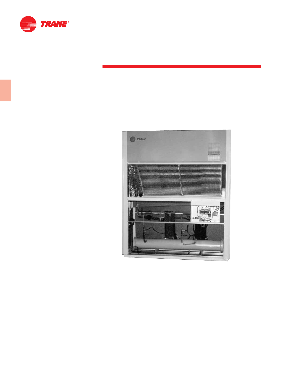
Air Handling Section
In accordance to the ASHRAE Standard
62-89 for Indoor Air Quality, Trane has
developed an exclusive and innovative
design for the drain pan. This design
insures proper drainage, preventing
conditions of water stagnation that could
result in microbial growth.
All the air handlers feature a factory
installed belt drive and ball bearing
evaporator fan with adjustable shelves.
The unit can be installed indoors; the
condenser air can be ducted to the
outside or installed in a remote location.
For free horizontal application, the
optional discharge plenum with
aluminum grills insures a quiet
operation and maintains the aesthetics
of the units.
In the return section an optional
aluminum grill grants an easy and
elegant installation.
How the Scroll Compressor Works
General
The compressor has two scrolls. The top
scroll is fixed and the bottom scroll
orbits. Each scroll has walls in a spiral
shape that intermesh.
3 Filter Types
To meet Commercial and Industrial
needs you can select the filter media for
the application.
Nylon Electrostatic Filters
Wire Mesh Permanent Filters
Throwaway Filters
Many other options available as special
(Contact your local Trane
Representative).
Scroll Compressor
offers significant efficiency and reliable
benefits. With fewer moving parts than
comparable reciprocating compressors,
there is less internal friction and
therefore greater efficiency. A smooth
compressor cycle, due to the low torque
variation, creates less stress on the
motor for greater reliability and
efficiency.
Inlet — First Orbit
As the bottom scroll orbits, two
refrigerant gas pockets are formed and
enclosed.
Compression — Second orbit
The refrigerant gas is compressed as the
volume is reduced closer to the center of
the scroll.
Discharge — Third Orbit
The gas is compressed further and
discharged through a small port in the
center of the fixed scroll.
5PKG-PRC007-EN
Page 6
Features and
Benefits
Integrated Self-Contained Systems:
Profitable, Simple
Integrated Comfort
Trane’s Integrated Comfort
improves job profit and increases job
control by combining Trane selfcontained units and a Tracker
management system. This integrated
system provides total building comfort
and control. The primary motivation for
building owners/managers in making the
purchasing decision of an HVAC controls
system is no longer just saving energy; it
is having the ability to automate their
facilities and the convenience of interface
to control systems.
™
System (ICS)
™
system
®
building
Genius is three times ingenious in many
ways.
Available in 3 models
SRVE - Self-contained unit with
INTEGRATED air cooled condenser
SIVE - Self contained unit with REMOTE
air-cooled condenser
SAVE - Self-contained WATER-cooled
unit with shell and tube condenser
Available 3 Colors
The attractive highly functional design of
the Genius line offers the customers the
selection of three equipment colors to
blend with any architectural style:
Gray
Black
Red
3 Motor Sizes
The units have the capability to meet any
static pressure application up to 1.5”
with their 3 options:
- Low Static Motor Option
- Medium Static Option
- High Static Option
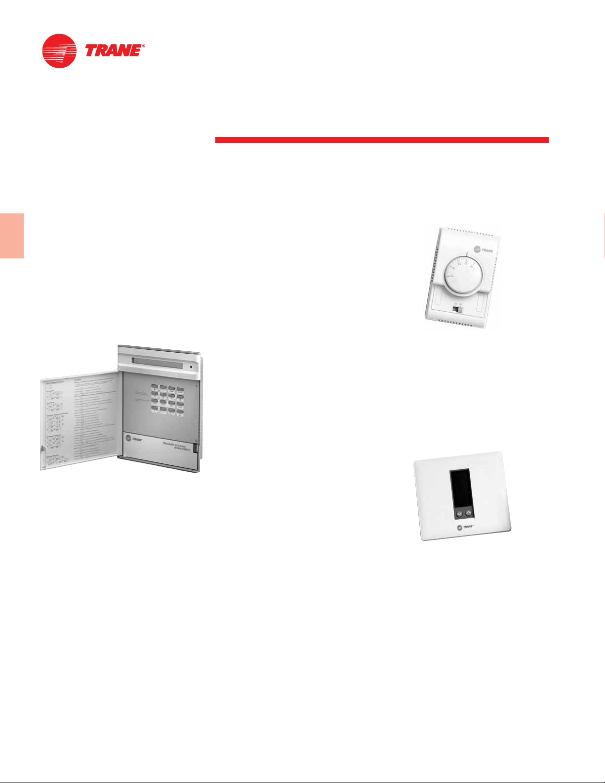
3 Control Options
Standard Thermostat
All units are furnished with a standard
thermostat that can be installed
remotely or directly on the equipment.
Programmable Thermostat (PT)
PT programming is very simple! PT has
a display that shows the hour, the day of
the week, the selected program and the
ambient temperature. PT can be
programmed for up to four setpoints for
each day of the week. Using the button
“timed-override” the customer can
prolong the machine operation beyond
the programmed schedule, according to
customer needs.
As an additional benefit the Micro
allows the Genius to be integrated to
the Tracker. This ability allows the
multiple units to be controlled and
diagnosed from a central location, from
across town or even across the country.
Just imagine the HVAC installed in your
facility capable of being scheduled,
monitored and let you know when it is
having problems.
Microcontrol
This state of the art control offers a
complete family of sensors and wall
mounted devices to compliment the
capabilities of the Trane Micro.
3 Filter Options
Three filter options exist which may be
installed in Genius units.
1. Permanent washable filters of
electrostatic fabric (standard).
2. Disposable 2” filters.
3. The combination of the two placed in
series.
PKG-PRC007-EN6
Page 7

Features Summary
Quality and Reliability
Galvanized steel casing
•
Synthetic enamel paint
•
Innovative Drain Pan
•
Scroll Compressors
•
Flexibility
Air or Water Cooled
•
Free discharge plenum or ducted
•
discharge
Voltages available:
•
220/3/60, 440/3/60, 380/3/60 and 380/50/3
Controls
Thermostat unit mounted or remote
•
Optional Programmable thermostat
•
Optional Microprocessor
•
ICS compatible, Tracker is your ideal
•
partner for small buildings applications.
Filters
Throwaway
•
Washable - Nylon type
•
Washable - Aluminum Mesh
•
Wide range of Models available:
SRVE: Self Contained with Integral Air Cooled Condenser
SIVE: Self Contained with Remote Air Condenser
SAVE: Self Contained with Water cooled
Nominal Capacity: From 5 to 15 Tons
You can reach up to 1.5” esp with our Double Inlet Forward curved
Supply fan. It also has variable V-belt drives.
The case has been insulated with BIDIM insulation.
Other options:
Aluminum decorative grill
Plenum discharge box for free air discharge
Service Valves
Sight Glass
Solenoid Valve
7PKG-PRC007-EN
Page 8
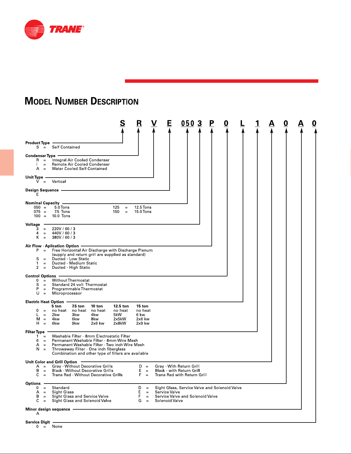
Model Number Description
PKG-PRC007-EN8
Page 9
General Data
Table GD-1 — Genius – General Data
SAVE Model 050 T 075 T 100 2T 125 2T 150 2T
Nominal TR Capacity 5 7.5 10 12.5 15
Length (mm) 960 1190 1500 1700 1700
Depth (mm) 600 600 600 600 600
Height (mm) 2000 2000 2000 2000 2000
Height w/ Plenum Box (mm) 2295 2295 2295 2295 2295
Net Weight (kg) 247 288 376 440 461
SRVE Model 050 T 075 T 100 2T 125 2T 150 2T
Nominal TR Capacity 5 7.5 10 12.5 15
Length (mm) 960 1190 1500 1700 1700
Depth (mm) 720 720 830 1000 1000
Height (mm) 2000 2000 2000 2000 2000
Height w/ Plenum Box (mm) 2295 2295 2295 2295 2295
Net Weight (kg) 268 310 416 459 490
SIVE Model 050 T 075 T 100 2T 125 2T 150 2T
Nominal TR Capacity 5 7.5 10 12.5 15
Evaporator Units
Quantity/Model 1/SIVE050 1/SIVE075 1/SIVE100 1/SIVE125 1/SIVE 150
Length (mm) 960 1190 1500 1700 1700
Depth (mm) 600 600 600 600 600
Height (mm) 2000 2000 2000 2000 2000
Height w/ Plenum Box (mm) 2295 2295 2295 2295 2295
Net Weight (kg) 190 225 235 347 392
Condensing Units
Quantity/Model 1/CRCB050 1/CRCB075 1/CRCB100 1/CRCB125 1/CRCB150
Length (mm) 987 1241 1341 1646 1646
Depth (mm) 631 631 631 714 714
Height (mm) 890 890 941 1018 1247
Net Weight (kg) 93 124 139 180 212
Compressor
Quantity TR 1 / 5 1 / 7.5 2 / 5 5 + 7.5 2 / 7.5
Evaporator Coil
Rows 3 3 3 3 4
Finned Height (mm) 536 508 612 663 714
Finned Length (mm) 711 965 1143 1328 1321
Finned Clearance (m) 0.38 0.49 0.70 0.88 0.94
FPF ( Fins Per Foot) 132 132 132 132 132
Evaporator Fan
Quantity 1 1 2 2 2
Diameter x Length 270 x 270 321 x 321 270 x 270 321 x 321 321 x 321
Plenum Box Option (CV) 0.5 0.5 0.5 0.5 1.0
Standard Motor Option (CV) 1.0 1.5 1.5 2.0 3.0
Motor Option 1 (CV) 1.0 2.0 2.0 3.0 4.0
Motor Option 2 (CV) 1.5 3.0 3.0 4.0 5.0
Minimum Air Flow (m
Maximum Air Flow (m3/h) 3825 5740 7650 9560 11475
Condenser Fan
(SRVE and CRCB)
Quantity 1 1 2 2 2
Diameter x Length 321 x 321 321 x 321 270 x 270 321 x 321 321 x 321
Motor (CV) 1.0 3.0 3.0 4.0 5.0
Air Flow (CFM) 5450 8315 9935 13930 17320
Water Condenser
(SAVE)
Minimum Water Flow GPM 1.4 2.0 2.7 3.4 4.1
Maximum Water Flow GPM 4.0 6.0 8.0 9.9 11.9
Maximum Pressure Drop (ca feet) 1.9 4.6 1.8 3.0 3.1
Condenser Coil
(SRVE, CRCB)
Rows 4 4 4 4 4
Finned Height (mm) 711 813 864 940 1168
Finned Length (mm) 762 1016 1143 1473 1473
FPF (Fins per Foot) 168 168 168 168 168
3
/h) 3060 4590 6120 7650 9180
9PKG-PRC007-EN
Page 10

Selection Procedure
The selection of a Genius self-contained
unit can be accomplished in three easy
steps.
1
LOAD: Determine the load requirements
for heating and cooling (include outside
air) using Trane’s load estimate forms,
®
TRACE
method.
2
UNIT TYPE: Self-contained air
conditioners are available in either
water-cooled or remote air-cooled
models to match individual needs.
3
SELECT THE UNIT: The conditions under
which the unit must operate and the
design load will give the final selection.
SELECTION EXAMPLE
Design Conditions
Water-cooled unit
Entering air temperature — 80/67 F
Total gross capacity required —
55,000 BTUH
Entering water temperature — 85 F
Leaving water temperature — 92 F
Airflow — 1,950 CFM at 0.5” duct static
pressure.
Voltage
Unit Selection
Tentatively select a 5-ton unit — Model
SAVE050. Refer to Table PD-6 to obtain
gross total and sensible unit capabilities,
gpm, and leaving water temperature at
nominal conditions:
Total MBh — 60.6
Sensible MBh — 43.5
GPM — 14.5
LWT — 95
The SAVE-050 meets the total and
sensible design requirements.
Easy/600 or any standard
Since the difference between entering
and leaving water is 7°F multiply the
capacities and water flow by correction
factors on Capacity Correction Factor
Table.
Cooling capacity multiplier 1.01
Sensible capacity multiplier 1.05
Water flow multiplier 1.39
60.6 x 1.01 = 61.21 MBh
43.5 x 1.01 = 43.94 MBh
14.5 x 1.39 = 20.16 GPM
Refer to Table PD-1 to determine
approximate brake horsepower and fan
rpm:
1035 rpm and 0.66 bhp.
Determine net capacities by subtracting
fan motor heat from gross capacities:
2.8 x 0.66 bph = 1.85 MBh
Net total capacity =
61.21 - 1.85 = 59.36 MBh
Net sensible capacity =
43.94 - 1.85 = 42.09 MBh
Supply air temperature DB
Q
= 1.085 x CFM x (Tr-TS)
s
42,090 = 1.085 x 1950 x (80-T
= 80 - 42,090
T
S
T
S
Air-Cooled
Design Conditions
— 80 F/67 F DB/WB return air
— 95 F Ambient
— 0.380 External Static Pressure
— 4200 CFM
— 0.25 External static pressure
Required
1. Select unit
2. Fan speed and BHP for
a) Evaporator fan
b) Condenser fan
3. Supply air temperature DB
(1.085) (1950)
= 60.1°F
temperature
— 109300 BTUH Total Net
— 76500 BTUH Sensible Net
(evaporator fan)
(condenser fan)
)
S
Solution
1. Select Unit
Initially Select a 10-Ton Unit
From Table PD-13
80/67 EAT
95 F AMB = 118.7 MBh Total Gross
4200 CFM 86.6 MBh Sensible
2. Fan speed and BHP determination
Total Static Pressure
Evaporator
0.380 esp
From Table PD-3
Evaporator
10-ton unit
4200 CFM = 1107 RPM
0.5 ESP = 1.63 BHP
Note: If values fall between cfm’s or
esp’s it is proper to interpolate between
values. Do not extrapolate beyond
values in catalog. Contact Trane
marketing department for assistance.
Fan Motor Heat Equation
Fan motor heat = 2.8 x 1.63 = 4.56 MBh
Net total capacity = 118.7 - 4.50
= 114.14 MBh
Net sensible capacity = 86.6 - 4.56
= 82.04 MBh
Conclusion:
Required — 109300 BTUH Total Net
76500 BTUH Total
Sensible Net
Provided — 114140 BTUH Total Net
82040 BTUH Total Net
The 10-ton unit is the proper choice for
this application.
PKG-PRC007-EN10
Page 11
Performance
Fan
Data
Data
Three transmission options exist for the
evaporator fan motor: Std. option,
option 1, option 2. In addition, there is an
option for those cases in which the unit
is operated with a plenum box. The
motors for each transmission option can
be found in the general facts tables.
Table PD-1 — Fan Performance SRVE/SIVE/SAVE 5 Tons
External static pressure with permanent air filter inches of water (Pa)
Option 5 TR CFM (m3/h) RPM BHP RPM BHP RPM BHP RPM BHP RPM BHP RPM BHP
STD FS: 184 (8") 2028 3443 897 0.56 931 0.59 964 0.62 996 0.65
Option 5 TR CFM (m3/h) RPM BHP RPM BHP RPM BHP RPM BHP RPM BHP RPM BHP RPM BHP RPM BHP RPM BHP
OP1 FS: 133 (6") 2028 3443 1027 0.68 1058 0.72 1117 0.79 1175 0.86 1230 0.94
Model Airflow (19.9) (39.8) (59.8) (77.2) (97.1) (124.5)
MT 1.0 CV 1877 3188 843 0.45 879 0.48 914 0.51 948 0.53 981 0.57
MS: 78,5 A 106,5 1952 3315 869 0.50 904 0.53 938 0.56 971 0.59 1003 0.62
B: 1X A36 2102 3570 925 0.62 957 0.65 989 0.68
Model Airflow (39.8) (59.8) (77.2) (97.1) (124.5) (156.9) (196.7) (234.1) (273.9)
MT 1.0 CV 1877 3188 1013 0.60 1076 0.67 1136 0.74 1195 0.81 1251 0.89
MS: 78,5 A 106,5 1952 3315 1035 0.66 1096 0.73 1155 0.80 1212 0.88
B: 1X A32 2102 3570 1020 0.71 1051 0.75 1081 0.78 1139 0.85 1195 0.93 1249 1.01
1802 3060 815 0.40 852 0.43 888 0.45 923 0.48 957 0.51 990 0.54
2178 3698 952 0.68 984 0.71
2253 3825 981 0.75
External static pressure with permanent air filter inches of water (Pa)
1802 3060 1055 0.61 1117 0.68 1176 0.75 1234 0.83
2178 3698 1015 0.74 1045 0.78 1075 0.81 1104 0.85 1160 0.92 1215 1.00
2253 3825 1012 0.78 1042 0.81 1071 0.85 1100 0.88 1128 0.92 1183 0.99 1237 1.07
.16 .24 .31 .39 .50 .63 .79 .94 1.10
.08 .16 .24 .31 .39 .50
External static pressure with permanent air filter inches of water (Pa)
Option 5 TR CFM (m3/h) RPM BHP RPM BHP RPM BHP RPM BHP RPM BHP
OP2 BS: 108 (5") 2028 3443 1284 1.02 1337 1.10 1387 1.18 1437 1.25
MT = Motor (CV).
MS = Motor Sheave, variable pitch (mm).
FS = Fan Sheave (mm).
B = Belt.
Model Airflow (234.1) (273.9) (313.7) (353.6) (390.9)
MT 1.5 CV 1877 3188 1305 0.97 1358 1.05 1409 1.12
MS: 78.5 A 106.5 1952 3315 1267 0.95 1320 1.03 1372 1.11 1422 1.19
B: 1X A31 2102 3570 1302 1.09 1353 1.16 1403 1.24 1452 1.32
1802 3060 1289 0.91 1343 0.98 1395 1.05
2178 3698 1269 1.08 1320 1.15 1371 1.23 1420 1.31 1467 1.39
2253 3825 1289 1.14 1340 1.22 1389 1.30 1437 1.39
.94 1.10 1.26 1.42 1.57
11PKG-PRC007-EN
Page 12

Performance
Fan
Data
Data
Table PD-2 — Fan Performance SRVE/SIVE/SAVE 7.5 Tons
External static pressure with permanent air filter inches of water (Pa)
Option 7.5 TR CFM (m3/h) RPM BHP RPM BHP RPM BHP RPM BHP RPM BHP RPM BHP
STD BS: 209 (9") 3041 5163 760 0.90 788 0.95 816 1.00 844 1.05 871 1.10
Option 7.5 TR CFM (m3/h) RPM BHP RPM BHP RPM BHP RPM BHP RPM BHP RPM BHP RPM BHP RPM BHP RPM BHP RPM BHP
OP1 BS: 159 (7") 3041 5163 897 1.15 949 1.25 999 1.36 1047 1.47 1094 1.59 1140 1.72
Model Airflow (19.9) (39.8) (59.8) (77.2) (97.1) (124.5)
MT 1.5 CV 2815 4780 712 0.72 743 0.76 773 0.81 802 0.86 831 0.91 859 0.96
MS: 78,5 A 106,5 2927 4970 735 0.81 765 0.85 794 0.90 822 0.95 850 0.99 877 1.05
B: 1X A35 3154 5355 784 1.01 811 1.06 838 1.10 865 1.15
Model Airflow (59.8) (77.2) (97.1) (124.5) (156.9) (196.7) (234.1) (273.9) (313.7) (353.6)
MT 2.0 CV 2815 4780 913 1.06 966 1.17 1017 1.28 1066 1.39 1113 1.50
MS: 78,5 A 106,5 2927 4970 931 1.16 982 1.26 1031 1.37 1079 1.49 1126 1.60
B: 1X A32 3154 5355 891 1.21 917 1.26 968 1.36 1016 1.47 1064 1.59 1110 1.71 1154 1.83
2703 4590 688 0.64 720 0.68 751 0.72 781 0.77 811 0.82 840 0.87
3267 5548 808 1.12 834 1.17 861 1.22
3380 5740 834 1.24 859 1.29
External static pressure with permanent air filter inches of water (Pa)
2703 4590 896 0.97 950 1.08 1002 1.19 1052 1.30 1100 1.41 1147 1.51
3267 5548 886 1.27 912 1.32 937 1.37 986 1.47 1034 1.58 1080 1.70 1125 1.83
3380 5740 885 1.34 910 1.39 935 1.44 959 1.49 1007 1.59 1053 1.70 1098 1.83 1142 1.96
.24 .31 .39 .50 .63 .79 .94 1.10 1.26 1.42
.08 .16 .24 .31 .39 .50
External static pressure with permanent air filter inches of water (Pa)
Option 7.5 TR CFM (m3/h) RPM BHP RPM BHP RPM BHP
OP2 BS: 118 (5") 3041 5163 1184 1.86 1227 2.03
MT = Motor (CV).
MS = Motor Sheave, variable pitch (mm).
FS = Fan Sheave (mm).
B = Belt.
Model Airflow (313.7) (353.6) (390.9)
MT 3.0 CV 2815 4780 1159 1.61 1204 1.75
MS: 80 A 110 2927 4970 1171 1.74 1215 1.88
B: 1X B27 3154 5355 1198 2.01 1240 2.17
2703 4590 1193 1.60
3267 5548 1169 1.97 1211 2.16 1253 2.34
3380 5740 1185 2.15 1227 2.32 1268 2.50
1.26 1.42 1.57
PKG-PRC007-EN12
Page 13
Performance
Fan
Data
Data
Table PD-3 — Fan Performance SRVE/SIVE/SAVE 10 Tons
External static pressure with permanent air filter inches of water (Pa)
Option 10 TR CFM (m3/h) RPM BHP RPM BHP RPM BHP RPM BHP RPM BHP
STD BS: 184 (8") 4055 6885 924 1.16 957 1.22 989 1.28
Option 10 TR CFM (m3/h) RPM BHP RPM BHP RPM BHP RPM BHP RPM BHP RPM BHP RPM BHP RPM BHP RPM BHP RPM BHP RPM BHP
OP1 BS: 133 (6") 4055 6885 1021 1.35 1051 1.42 1082 1.49 1140 1.64 1197 1.79
Model Airflow (19.9) (39.8) (59.8) (77.2) (97.1)
MT 1.5 CV 3754 6375 866 0.94 902 0.99 936 1.05 969 1.11 1002 1.17
MS: 78,5 A 106,5 3905 6630 895 1.04 929 1.10 963 1.16 995 1.23
B: 1X A35 4205 7140 954 1.29 986 1.35
Model Airflow (19.9) (39.8) (59.8) (77.2) (97.1) (124.5) (156.9) (196.7) (234.1) (273.9) (313.7)
MT 2.0 CV 3754 6375 1034 1.24 7096 1.38 1156 1.53 1213 1.68 1269 1.83
MS: 78,5 A 106,5 3905 6630 1027 1.29 1058 1.36 1118 1.51 1176 1.66 1232 1.81
B: 1X A31 4205 7140 1017 1.42 1048 1.49 1078 1.56 1107 1.63 1164 1.78
3604 6120 839 0.84 875 0.89 911 0.94 945 1.00 979 1.07
4355 7395 984 1.42
4505 7650
External static pressure with permanent air filter inches of water (Pa)
.08 .16 .24 .31 .39 .50 .63 .79 .94 1.10 1.26
3604 6120 1012 1.13 1075 1.26 1136 1.41 1195 1.55 1252 1.71 1307 1.87
4355 7395 1015 1.49 1045 1.55 1075 1.63 1104 1.70 1132 1.77
4505 7650 1013 1.56 1043 1.63 1072 1.70 1101 1.77 1130 1.84 1157 1.92
.08 .16 .24 .31 .39
External static pressure with permanent air filter inches of water (Pa)
Option 10 TR CFM (m3/h) RPM BHP RPM BHP RPM BHP RPM BHP RPM BHP RPM BHP RPM BHP
OP2 BS: 118 (5") 4055 6885 1252 1.94 1305 2.10 1357 2.26 1407 2.42 1456 2.57
MT = Motor (CV).
MS = Motor Sheave, variable pitch (mm).
FS = Fan Sheave (mm).
B = Belt.
Model Airflow (156.9) (96.7) (234.1) (273.9) (313.7) (353.6) (390.9)
MT 3.0 CV 3754 6375 1322 1.98 1375 2.14 1425 2.29
MS: 80 A 110 3905 6630 1287 1.97 1340 2.12 1391 2.28 1441 2.43
B: 1X B31 4205 7140 1220 1.93 1273 2.08 1325 2.24 1376 2.40 1425 2.56 1473 2.71
3604 6120 1360 2.01 1412 2.16
4355 7395 1188 1.92 1242 2.07 1295 2.23 1346 2.39 1395 2.54 1444 2.71
4505 7650 1212 2.06 1265 2.22 1316 2.37 1366 2.53 1414 2.69
.63 .79 .94 1.10 1.26 1.42 1.57
13PKG-PRC007-EN
Page 14

Performance
Fan
Data
Data
Table PD-4 — Fan Performance SRVE/SIVE/SAVE 12.5 Tons
External static pressure with permanent air filter inches of water (Pa)
Model Airflow (19.9) (39.8) (59.8) (77.2) (97.1) (124.5) (156.9)
Option 12.5 TR CFM (m3/h) RPM BHP RPM BHP RPM BHP RPM BHP RPM BHP RPM BHP RPM BHP
MT 2.0 CV 4694 7970 649 0.93 684 1.01 718 1.09 751 1.18 783 1.27 814 1.37
MS: 78,5 A 106,5 4882 8290 670 1.04 703 1.12 736 1.20 768 1.29 799 1.39 830 1.49
STD BS: 184 (8") 5069 8608 690 1.15 723 1.24 754 1.32 785 1.41 816 1.51 845 1.61
B: 1X A33 5256 8925 711 1.28 743 1.37 774 1.46 804 1.55 833 1.65 862 1.75
Option 12.5 TR CFM (m3/h) RPM BHP RPM BHP RPM BHP RPM BHP RPM BHP RPM BHP
OP1 FS: 169 (7") 5069 8608 902 1.82 957 2.04 1010 2.26 1060 2.48
Option 12.5 TR CFM (m3/h) RPM BHP RPM BHP RPM BHP RPM BHP RPM BHP
OP2 FS: 143 (6") 5069 8608 1109 2.69 1156 2.89 1203 3.13
MT = Motor (CV).
MS = Motor Sheave, variable pitch (mm).
FS = Fan Sheave (mm).
B = Belt.
Model Airflow (97.1) (124.5) (156.9) (195.7) (234.1) (273.9)
MT 3.0 CV 4694 7970 874 1.57 931 1.79 985 2.00 1038 2.23
MS: 79 A 105 4882 8290 888 1.69 944 1.91 997 2.13 1049 2.35
B: 1X B32 5256 8925 918 1.97 971 2.18 1023 2.40
Model Airflow (234.1) (273.9) (313.7) (353.6) (390.9)
MT 4.0 CV 4694 7970 1089 2.44 1139 2.65 1187 2.81
MS: 79 A 105 4882 8290 1099 2.56 1148 2.77 1195 2.92
B: 1X B29 5256 8925 1073 2.62 1121 2.84 1167 2.95 1213 3.20
4505 7650 630 0.81 666 0.89 701 0.98 735 1.08 768 1.18 800 1.29 8.61 1.50
5445 9243 731 1.41 762 1.50 792 1.60 821 1.69 850 1.79
5630 9560 753 1.56 783 1.65 812 1.75 841 1.85
External static pressure with permanent air filter inches of water (Pa)
4505 7650 919 1.62 975 1.88 1029 2.06
5445 9243 878 1.90 932 2.11 985 2.33 1035 2.55
5630 9560 868 1.95 896 2.06 949 2.27 1000 2.49
External static pressure with permanent air filter inches of water (Pa)
4505 7650 1081 2.26 1131 2.52 1179 2.73
5445 9243 1084 2.77 1131 2.98 1177 3.10
5630 9560 1050 2.71 1098 2.93 1144 3.15 1189 3.30
.08 .16 .24 .31 .39 .50 .63
.39 .50 .63 .79 .94 1.10
.94 1.10 1.26 1.42 1.57
PKG-PRC007-EN14
Page 15

Performance
Fan
Data
Data
Table PD-5 — Fan Performance SRVE/SIVE/SAVE 15 Tons
External static pressure with permanent air filter inches of water (Pa)
Option 15 TR CFM (m3/h) RPM BHP RPM BHP RPM BHP RPM BHP RPM BHP RPM BHP
STD FS: 219 (9") 6080 10323 728 1.69 757 1.79 785 1.89 813 1.99
Option 7.5 TR CFM (m3/h) RPM BHP RPM BHP RPM BHP RPM BHP RPM BHP RPM BHP RPM BHP RPM BHP RPM BHP RPM BHP
OP1 FS: 169 (7") 6080 10323 841 2.09 868 2.19 921 2.40 972 2.61 1021 2.83 1069 3.06
Model Airflow (19.9) (39.8) (59.8) (77.2) (97.1) (124.5)
MT 3.0 CV 5632 9563 686 1.36 717 1.45 747 1.54 777 1.64 806 1.73
MS: 79 A 105 5857 9945 707 1.52 737 1.61 766 1.71 795 1.81
B: 1X B35 6302 10700 749 1.88 777 1.98 804 2.08
Model Airflow (39.8) (59.8) (77.2) (97.1) (124.5) (156.9) (196.7) (234.1) (273.9) (313.7)
MT 4.0 CV 5632 9563 835 1.83 890 2.03 944 2.25 995 2.47 1045 2.69
MS: 79 A 105 5857 9945 824 1.91 852 2.01 906 2.21 958 2.43 1008 2.65 1057 2.87
B: 1X B31 6302 10700 832 2.19 858 2.28 885 2.39 936 2.59 986 2.80 1034 3.02
5406 9180 664 1.22 696 1.30 728 1.38 759 1.48 789 1.57 818 1.66
6530 11088 771 2.08 798 2.19
6758 11475 793 2.30
External static pressure with permanent air filter inches of water (Pa)
5406 9180 875 1.87 930 2.08 983 2.30 1033 2.52 1082 2.74
6530 11088 825 2.29 851 2.40 877 2.50 903 2.60 953 2.81 1002 3.02 1049 3.24
6758 11475 819 2.41 845 2.52 871 2.62 896 2.72 921 2.85 970 3.03 1017 3.23 1064 3.46
.16 .24 .31 .39 .50 .63 .79 .94 1.10 1.26
.08 .16 .24 .31 .39 .50
External static pressure with permanent air filter inches of water (Pa)
Option 15 TR CFM (m3/h) RPM BHP RPM BHP RPM BHP RPM BHP
OP2 FS: 143 (6") 6080 10323 1115 3.29 1160 3.53 1204 3.80
MT = Motor (CV).
MS = Motor Sheave, variable pitch (mm).
FS = Fan Sheave (mm).
B = Belt.
Model Airflow (273.9) (313.7) (353.6) (390.9)
5406 9180 1130 2.95 1176 3.17
MT 5.0 CV 5632 9563 1093 2.91 1140 3.13 1185 3.37
MS: 79 A 105 5857 9945 1104 3.10 1150 3.33 1194 3.58
B: 1X B29 6302 10700 1081 3.26 1126 3.50 1171 3.77 1214 4.02
6530 11088 1095 3.48 1139 3.74 1183 4.00 1225 4.27
6758 11475 1108 3.71 1152 4.00 1195 4.20 1236 4.45
1.10 1.26 1.42 1.57
15PKG-PRC007-EN
Page 16

Performance
Water Cooled
Data
60 Hz
Table PD-6 — Gross Cooling Capacities SAVE-050 English
75 85
Ent. 61 67 73 61 67 73
DB
CFM (°F) TGC SHC GPM TGC SHC GPM TGC SHC GPM TGC SHC GPM TGC SHC GPM TGC SHC GPM
75 55.0 45.2 12.8 61.6 35.2 14.5 68.6 24.9 15.9 53.5 44.4 12.8 59.9 34.4 14.5 67.0 24.4 15.9
1800 80 55.2 53.1 12.8 61.5 43.4 14.5 68.6 33.1 15.9 53.7 52.3 12.8 59.9 42.6 14.5 66.8 32.4 15.9
85 56.7 57.8 13.2 61.5 50.1 14.5 68.5 39.8 15.9 55.4 56.5 13.2 59.8 49.4 14.1 66.8 39.2 15.9
90 59.2 60.4 14.1 61.5 56.7 14.5 68.5 46.5 15.9 58.0 59.1 14.1 59.9 56.0 14.5 66.7 45.9 15.9
75 55.7 46.6 13.2 62.3 36.0 14.5 69.4 25.2 15.9 54.1 45.9 13.2 60.7 35.3 14.5 67.7 24.6 15.9
1950 80 56.0 54.9 13.2 62.3 44.7 14.5 69.3 33.8 15.9 54.6 54.1 13.2 60.6 43.5 14.5 67.7 33.2 15.9
85 58.0 59.1 13.7 62.2 51.9 14.5 69.3 41.0 15.9 56.7 57.8 13.7 60.6 51.1 14.5 67.6 40.3 15.9
90 60.7 61.8 14.1 63.4 58.8 14.5 69.2 48.1 15.9 59.4 60.6 14.1 60.8 58.1 14.5 67.6 47.5 15.9
75 56.3 48.1 13.2 62.9 36.9 14.5 70.1 25.4 16.3 54.7 47.4 13.2 61.3 36.1 14.5 68.4 24.8 16.3
2100 80 56.9 56.6 13.7 62.9 46.0 14.5 70.0 34.5 16.3 55.4 55.7 13.2 61.3 45.3 14.5 68.3 33.9 15.9
85 59.1 60.3 14.1 62.8 53.6 14.5 70.0 42.1 16.3 57.9 59.0 14.1 61.2 52.8 14.5 68.3 41.5 15.9
90 61.9 63.1 14.5 63.1 60.8 14.5 69.9 49.7 16.3 60.7 61.8 14.5 61.6 60.0 14.5 68.2 49.0 15.9
75 56.9 49.5 13.7 63.5 37.6 15.0 70.8 25.6 16.3 55.2 48.7 13.2 61.9 37.0 14.5 69.0 25.0 16.3
2250 80 57.7 58.1 13.7 63.5 47.3 15.0 70.7 35.3 16.3 56.2 57.0 13.7 61.8 46.5 14.5 68.9 34.5 16.3
85 60.3 61.4 14.1 63.4 55.2 15.0 70.7 43.2 16.3 58.9 60.1 14.1 61.8 54.5 14.5 68.9 42.5 16.3
90 63.1 64.4 14.5 64.0 62.6 15.0 70.6 51.1 16.3 61.8 63.0 14.5 62.3 61.7 15.0 68.8 50.5 16.3
ENT Water Temp (°F)
Entering Wet Bulb Temperature (°F)
Table PD-6 — Gross Cooling Capacities SAVE-050 (Cont.)
ENT Water Temp (°F)
Ent. 61 67 73
DB
CFM (°F) TGC SHC GPM TGC SHC GPM TGC SHC GPM
75 51.9 43.7 12.8 58.3 33.7 14.1 65.2 23.6 15.9
1800 80 52.2 51.5 12.8 58.2 41.9 14.1 65.1 31.8 15.9
85 54.2 55.2 13.7 58.2 48.6 14.1 65.1 38.5 15.9
90 56.8 57.9 14.1 58.3 55.2 14.1 65.0 45.3 15.9
75 52.5 45.2 13.2 59.0 34.5 14.5 65.9 23.8 15.9
1950 80 53.0 53.1 13.2 58.9 43.3 14.5 65.8 32.6 15.9
85 55.4 56.5 13.7 58.9 50.4 14.5 65.8 39.7 15.9
90 58.1 59.2 14.1 59.1 57.2 14.5 65.7 46.8 15.9
75 53.1 46.6 13.2 59.6 35.4 14.5 66.5 24.2 15.9
2100 80 54.0 54.6 13.7 59.5 44.5 14.5 66.5 33.3 15.9
85 56.5 57.6 14.1 59.5 52.2 14.5 66.4 40.8 15.9
90 59.3 60.5 14.5 59.9 59.1 14.5 66.4 48.3 15.9
75 53.7 48.0 13.2 60.2 36.2 14.5 67.2 24.4 16.3
2250 80 54.8 55.9 13.7 60.1 45.8 14.5 67.1 33.9 16.3
85 57.6 58.7 14.1 60.1 53.8 14.5 67.1 41.9 16.3
Notes:
TGC = Total Gross Capacity (MBh)
SHC = Sensible Heat Capacity (MBh)
90 60.4 61.5 15.0 60.8 60.8 15.0 67.0 49.8 16.3
Entering Wet Bulb Temperature (°F)
95
Capacity Correction Factor Table
Delta T
Water Total Cap. Sens. Cap.
(°F) GPM MBh MBh
4.5 2.21 1.01 1.01
7.2 1.39 1.01 1.01
10.0 1.00 1.00 1.00
12.6 0.79 0.99 1.00
15.3 0.66 0.99 1.00
18.0 0.56 0.98 0.99
PKG-PRC007-EN16
Page 17

Performance
Water Cooled
Data
60 Hz
Table PD-6 — Gross Cooling Capacities SAVE-050 Metric
24.0 29.5
Ent. 16.0 19.5 23.0 16.0 19.5 23.0
DB
m3/h (°C) TGC SHC l/s TGC SHC l/s TGC SHC l/s TGC SHC l/s TGC SHC l/s TGC SHC l/s
24 16.1 13.2 0.81 18.0 10.3 0.92 20.1 7.3 1.00 15.7 13.0 0.81 17.6 10.1 0.92 19.6 7.1 1.00
3060 27 16.2 15.6 0.81 18.0 12.7 0.92 20.1 9.7 1.00 15.7 15.3 0.81 17.6 12.5 0.92 19.6 9.5 1.00
29 16.6 16.9 0.83 18.0 14.7 0.92 20.1 11.7 1.00 16.2 16.6 0.83 17.5 14.5 0.89 19.6 11.5 1.00
32 17.4 17.7 0.89 18.0 16.6 0.92 20.1 13.6 1.00 17.0 17.3 0.89 17.6 16.4 0.92 19.6 13.4 1.00
24 16.3 13.7 0.83 18.3 10.6 0.92 20.3 7.4 1.00 15.8 13.4 0.83 17.8 10.3 0.92 19.8 7.2 1.00
3315 27 16.4 16.1 0.83 18.3 13.1 0.92 20.3 9.9 1.00 16.0 15.8 0.83 17.7 12.8 0.92 19.8 9.7 1.00
29 17.0 17.3 0.86 18.2 15.2 0.92 20.3 12.0 1.00 16.6 16.9 0.86 17.7 15.0 0.92 19.8 11.8 1.00
32 17.8 18.1 0.89 18.6 17.2 0.92 20.3 14.1 1.00 17.4 17.8 0.89 17.8 17.0 0.92 19.8 13.9 1.00
24 16.5 14.1 0.83 18.4 10.8 0.92 20.6 7.4 1.03 16.0 13.9 0.83 18.0 10.6 0.92 20.0 7.3 1.03
3570 27 16.7 16.6 0.86 18.4 13.5 0.92 20.5 10.1 1.03 16.2 16.3 0.83 18.0 13.3 0.92 20.0 9.9 1.00
29 17.3 17.7 0.89 18.4 15.7 0.92 20.5 12.3 1.03 17.0 17.3 0.89 17.9 15.5 0.92 20.0 12.2 1.00
32 18.1 18.5 0.92 18.5 17.8 0.92 20.5 14.6 1.03 17.8 18.1 0.92 18.0 17.6 0.92 20.0 14.4 1.00
24 16.7 14.5 0.86 18.6 11.0 0.94 20.7 7.5 1.03 16.2 14.3 0.83 18.1 10.8 0.92 20.2 7.3 1.03
3825 27 16.9 17.0 0.86 18.6 13.8 0.94 20.7 10.3 1.03 16.5 16.7 0.86 18.1 13.6 0.92 20.2 10.1 1.03
29 17.7 18.0 0.89 18.6 16.2 0.94 20.7 12.6 1.03 17.3 17.6 0.89 18.1 16.0 0.92 20.2 12.5 1.03
32 18.5 18.9 0.92 18.7 18.3 0.94 20.7 15.0 1.03 18.1 18.5 0.92 18.3 18.1 0.94 20.2 14.8 1.03
ENT Water Temp (°C)
Entering Wet Bulb Temperature (°C)
Table PD-6 — Gross Cooling Capacities SAVE-050 (Cont.)
ENT Water Temp (°C)
Ent. 16.0 19.5 23.0
DB
m3/h (°C) TGC SHC l/s TGC SHC l/s TGC SHC l/s
24 15.2 12.8 0.81 17.1 9.9 0.89 19.1 6.9 1.00
3060 27 15.3 15.1 0.81 17.1 12.3 0.89 19.1 9.3 1.00
29 15.9 16.2 0.86 17.1 14.2 0.89 19.1 11.3 1.00
32 16.6 17.0 0.89 17.1 16.2 0.89 19.0 13.3 1.00
24 15.4 13.2 0.83 17.3 10.1 0.92 19.3 7.0 1.00
3315 27 15.5 15.6 0.83 17.3 12.7 0.92 19.3 9.5 1.00
29 16.2 16.6 0.86 17.3 14.8 0.92 19.3 11.6 1.00
32 17.0 17.4 0.89 17.3 16.8 0.92 19.3 13.7 1.00
24 15.6 13.7 0.83 17.5 10.4 0.92 19.5 7.1 1.00
3570 27 15.8 16.0 0.86 17.4 13.0 0.92 19.5 9.8 1.00
29 16.6 16.9 0.89 17.4 15.3 0.92 19.5 12.0 1.00
32 17.4 17.7 0.92 17.6 17.3 0.92 19.5 14.2 1.00
24 15.7 14.1 0.83 17.6 10.6 0.92 19.7 7.1 1.03
3825 27 16.1 16.4 0.86 17.6 13.4 0.92 19.6 9.9 1.03
29 16.9 17.2 0.89 17.6 15.8 0.92 19.6 12.3 1.03
Notes:
TGC = Total Gross Capacity (kW)
SHC = Sensible Heat Capacity (kW)
32 17.7 18.0 0.94 17.8 17.8 0.94 19.6 14.6 1.03
Entering Wet Bulb Temperature (°C)
35.0
Capacity Correction Factor Table
Delta T
Water Total Cap. Sens. Cap.
(°C) l/s kW kW
2.5 2.21 1.01 1.01
4.0 1.39 1.01 1.01
5.5 1.00 1.00 1.00
7.0 0.79 0.99 1.00
8.5 0.66 0.99 1.00
10.0 0.56 0.98 0.99
17PKG-PRC007-EN
Page 18

Performance
Water Cooled
Data
60 Hz
Table PD-7 — Gross Cooling Capacities SAVE-075 English
75 85
Ent. 61 67 73 61 67 73
DB
CFM (°F) TGC SHC GPM TGC SHC GPM TGC SHC GPM TGC SHC GPM TGC SHC GPM TGC SHC GPM
75 79.4 64.2 18.1 89.4 49.9 19.8 100.1 35.3 22.0 77.2 63.1 18.1 86.8 48.8 19.8 97.1 34.2 22.0
2700 80 79.8 75.6 18.1 89.3 61.6 19.8 100.0 47.0 22.0 77.7 74.3 18.1 86.7 60.6 19.8 97.0 46.0 22.0
85 82.5 81.7 18.5 89.1 71.5 19.8 99.9 56.8 22.0 80.6 79.8 18.5 86.6 70.4 19.8 97.0 55.8 22.0
90 86.5 85.7 19.4 89.4 81.1 19.8 99.7 66.6 22.0 84.5 83.7 19.4 86.8 79.9 19.8 96.9 65.5 21.6
75 80.5 66.3 18.1 90.4 51.1 20.3 101.2 35.7 22.5 78.1 65.2 18.1 87.9 50.0 20.3 98.3 34.5 22.0
2925 80 81.1 78.1 18.5 90.3 63.6 20.3 101.1 48.2 22.5 79.0 76.8 18.5 87.6 63.0 20.3 98.2 47.0 22.0
85 84.4 83.6 18.9 90.3 74.0 20.3 101.0 58.5 22.0 82.5 81.7 18.9 87.6 72.9 20.3 98.1 57.4 22.0
90 88.5 87.7 19.8 90.6 84.0 20.3 100.9 68.8 22.0 86.5 85.7 19.8 88.1 82.7 20.3 97.9 67.7 22.0
75 81.3 68.4 18.5 91.5 52.3 20.3 102.3 36.0 22.5 79.0 67.2 18.5 88.7 51.2 20.3 99.2 34.9 22.5
3150 80 124.4 80.3 18.5 91.4 65.5 20.3 102.2 49.1 22.5 80.2 78.9 18.5 88.6 64.4 20.3 99.1 48.1 22.5
85 86.1 85.3 19.4 91.3 76.4 20.3 102.1 60.1 22.5 84.1 83.3 19.4 88.6 75.4 20.3 99.0 59.0 22.5
90 90.3 89.5 20.3 91.8 86.7 20.3 102.0 71.0 22.5 88.3 87.5 20.3 89.3 85.4 20.3 98.9 69.8 22.0
75 82.2 70.2 18.5 92.3 53.4 20.7 103.1 36.3 22.5 79.7 69.2 18.5 89.6 52.3 20.3 100.1 35.2 22.5
3375 80 83.5 82.3 18.9 92.2 67.3 20.3 103.0 50.2 22.5 81.4 80.6 18.9 89.5 66.2 20.3 100.0 49.0 22.5
85 87.7 86.8 19.8 92.1 78.9 20.7 103.0 61.6 22.5 85.6 84.8 19.8 89.4 77.7 20.3 99.9 60.5 22.5
90 92.1 91.2 20.3 93.0 89.3 20.7 102.9 73.1 22.5 89.9 89.0 20.3 90.4 87.8 20.7 99.7 71.9 22.5
ENT Water Temp (°F)
Entering Wet Bulb Temperature (°F)
Table PD-7 — Gross Cooling Capacities SAVE-075 (Cont.)
ENT Water Temp (°F)
Ent. 61 67 73
DB
CFM (°F) TGC SHC GPM TGC SHC GPM TGC SHC GPM
75 74.7 62.0 18.1 84.1 47.7 19.8 94.0 33.2 21.6
2700 80 75.4 73.0 18.1 84.0 59.4 19.8 94.0 44.9 21.6
85 78.5 77.8 18.5 84.0 69.2 19.8 93.9 54.6 21.6
90 82.5 81.7 19.4 84.3 78.6 19.8 93.8 64.4 21.6
75 75.6 63.0 18.1 85.0 48.9 19.8 95.1 33.5 22.0
2925 80 76.7 75.2 18.5 84.9 61.4 19.8 95.0 46.0 22.0
85 80.3 79.6 18.9 84.9 71.7 19.8 95.0 56.3 22.0
90 84.4 83.6 19.8 85.5 81.4 20.3 94.9 66.6 22.0
75 76.4 66.0 18.1 85.9 50.1 20.3 96.0 33.8 22.0
3150 80 78.0 77.1 18.5 85.8 63.2 20.3 95.9 46.9 22.0
85 81.9 81.2 19.4 85.8 74.1 20.3 95.8 57.9 22.0
90 86.1 85.3 20.3 86.7 83.9 20.3 95.7 68.8 22.0
75 77.2 68.0 18.5 86.6 51.1 20.3 96.8 34.1 22.5
3375 80 79.3 78.5 18.9 86.5 65.0 20.3 96.7 47.9 22.5
85 83.4 82.6 19.8 86.5 76.4 20.3 96.7 59.4 22.0
Notes:
TGC = Total Gross Capacity (MBh)
SHC = Sensible Heat Capacity (MBh)
90 87.6 86.7 20.3 87.9 86.1 20.3 96.6 70.8 22.0
Entering Wet Bulb Temperature (°F)
95
Capacity Correction Factor Table
Delta T
Water Total Cap. Sens. Cap.
(°F) GPM MBh MBh
4.5 2.21 1.01 1.01
7.2 1.39 1.01 1.01
10.0 1.00 1.00 1.00
12.6 0.79 0.99 1.00
15.3 0.66 0.99 1.00
18.0 0.56 0.98 0.99
PKG-PRC007-EN18
Page 19

Performance
Water Cooled
Data
60 Hz
Table PD-7 — Gross Cooling Capacities SAVE-075 Metric
24.0 29.5
Ent. 16.0 19.5 23.0 16.0 19.5 23.0
DB
m3/h (°C) TGC SHC l/s TGC SHC l/s TGC SHC l/s TGC SHC l/s TGC SHC l/s TGC SHC l/s
24 23.3 18.8 1.14 26.2 14.6 1.25 29.3 10.3 1.39 22.6 18.5 1.14 25.4 14.3 1.25 28.4 10.0 1.39
4590 27 23.4 22.2 1.14 26.2 18.1 1.25 29.3 13.8 1.39 22.8 21.8 1.14 25.4 17.8 1.25 28.4 13.5 1.39
29 24.2 23.9 1.17 26.1 21.0 1.25 29.3 16.6 1.39 23.6 23.4 1.17 25.4 20.6 1.25 28.4 16.3 1.39
32 25.3 25.1 1.22 26.2 23.8 1.25 29.2 19.5 1.39 24.8 24.5 1.22 25.4 23.4 1.25 28.4 19.2 1.36
24 23.6 19.4 1.14 26.5 15.0 1.28 29.7 10.5 1.42 22.9 19.1 1.14 25.7 14.6 1.28 28.8 10.1 1.39
4970 27 23.8 22.9 1.17 26.5 18.6 1.28 29.6 14.1 1.42 23.1 22.5 1.17 25.7 18.5 1.28 28.8 13.8 1.39
29 24.7 24.5 1.19 26.5 21.7 1.28 29.6 17.1 1.39 24.2 23.9 1.19 25.7 21.4 1.28 28.7 16.8 1.39
32 25.9 25.7 1.25 26.6 24.6 1.28 29.6 20.2 1.39 25.3 25.1 1.25 25.8 24.2 1.28 28.7 19.8 1.39
24 23.8 20.0 1.17 26.8 15.3 1.28 30.0 10.6 1.42 23.1 19.7 1.17 26.0 15.0 1.28 29.1 10.2 1.42
5355 27 36.5 23.5 1.17 26.8 19.2 1.28 29.9 14.4 1.42 23.5 23.1 1.17 26.0 18.9 1.28 29.0 14.1 1.42
29 25.2 25.0 1.22 26.7 22.4 1.28 29.9 17.6 1.42 24.6 24.4 1.22 26.0 22.1 1.28 29.0 17.3 1.42
32 26.5 26.2 1.28 26.9 25.4 1.28 29.9 20.8 1.42 25.9 25.6 1.28 26.2 25.0 1.28 29.0 20.5 1.39
24 24.1 20.6 1.17 27.1 15.7 1.31 30.2 10.6 1.42 23.4 20.3 1.17 26.2 15.3 1.28 29.3 10.3 1.42
5740 27 24.5 24.1 1.19 27.0 19.7 1.28 30.2 14.7 1.42 23.9 23.6 1.19 26.2 19.4 1.28 29.3 14.4 1.42
29 25.7 25.4 1.25 27.0 23.1 1.31 30.2 18.1 1.42 25.1 24.9 1.25 26.2 22.8 1.28 29.3 17.7 1.42
32 27.0 26.7 1.28 27.2 26.2 1.31 30.2 21.4 1.42 26.3 26.1 1.28 26.5 25.7 1.31 29.2 21.1 1.42
ENT Water Temp (°C)
Entering Wet Bulb Temperature (°C)
Table PD-7 — Gross Cooling Capacities SAVE-075 (Cont.)
ENT Water Temp (°C)
Ent. 16.0 19.5 23.0
DB
m3/h (°C) TGC SHC l/s TGC SHC l/s TGC SHC l/s
24 21.9 18.2 1.14 24.6 14.0 1.25 27.5 9.7 1.36
4590 27 22.1 21.4 1.14 24.6 17.4 1.25 27.5 13.2 1.36
29 23.0 22.8 1.17 24.6 20.3 1.25 27.5 16.0 1.36
32 24.2 23.9 1.22 24.7 23.0 1.25 27.5 18.9 1.36
24 22.1 18.5 1.14 24.9 14.3 1.25 27.9 9.8 1.39
4970 27 22.5 22.0 1.17 24.9 18.0 1.25 27.8 13.5 1.39
29 23.5 23.3 1.19 24.9 21.0 1.25 27.8 16.5 1.39
32 24.7 24.5 1.25 25.1 23.8 1.28 27.8 19.5 1.39
24 22.4 19.4 1.14 25.2 14.7 1.28 28.1 9.9 1.39
5355 27 22.9 22.6 1.17 25.1 18.5 1.28 28.1 13.8 1.39
29 24.0 23.8 1.22 25.1 21.7 1.28 28.1 17.0 1.39
32 25.2 25.0 1.28 25.4 24.6 1.28 28.0 20.2 1.39
24 22.6 19.9 1.17 25.4 15.0 1.28 28.4 10.0 1.42
5740 27 23.2 23.0 1.19 25.3 19.0 1.28 28.3 14.0 1.42
29 24.4 24.2 1.25 25.3 22.4 1.28 28.3 17.4 1.39
Notes:
TGC = Total Gross Capacity (kW)
SHC = Sensible Heat Capacity (kW)
32 25.7 25.4 1.28 25.7 25.2 1.28 28.3 20.7 1.39
Entering Wet Bulb Temperature (°C)
35.0
Capacity Correction Factor Table
Delta T
Water Total Cap. Sens. Cap.
(°C) l/s kW kW
2.5 2.21 1.01 1.01
4.0 1.39 1.01 1.01
5.5 1.00 1.00 1.00
7.0 0.79 0.99 1.00
8.5 0.66 0.99 1.00
10.0 0.56 0.98 0.99
19PKG-PRC007-EN
Page 20

Performance
Water Cooled
Data
60 Hz
Table PD-8 — Gross Cooling Capacities SAVE-100 English
75 85
Ent. 61 67 73 61 67 73
DB
CFM (°F) TGC SHC GPM TGC SHC GPM TGC SHC GPM TGC SHC GPM TGC SHC GPM TGC SHC GPM
75 109.9 87.9 26.0 122.7 68.5 28.6 136.6 48.7 31.7 106.7 86.3 26.0 119.5 67.1 28.6 133.2 47.5 31.3
3600 80 110.1 103.3 26.0 122.6 84.1 28.6 136.5 64.4 31.7 107.1 101.7 26.0 119.4 82.7 28.6 133.1 63.1 31.3
85 112.7 112.7 26.9 122.5 97.1 28.6 136.4 77.4 31.7 110.1 110.1 26.9 119.3 95.8 28.6 133.0 76.1 31.3
90 117.7 117.7 27.8 122.5 110.0 28.6 136.3 90.3 31.7 115.3 115.3 27.8 119.3 108.6 28.6 132.9 89.0 31.3
75 111.2 90.7 26.4 124.2 70.1 29.1 138.2 49.2 31.7 108.0 89.2 26.4 120.9 68.7 29.1 134.7 47.9 31.7
3900 80 111.8 106.8 26.4 124.1 86.7 29.1 138.0 65.8 31.7 108.8 105.1 26.4 120.7 85.3 29.1 134.6 64.6 31.7
85 115.3 115.3 27.3 124.0 100.5 29.1 137.9 79.6 31.7 112.7 112.7 27.3 120.7 99.1 29.1 134.5 78.3 31.7
90 120.5 120.5 28.2 124.1 114.0 29.1 137.8 93.3 31.7 117.9 117.9 28.2 120.9 112.5 29.1 134.4 92.0 31.7
75 112.5 93.4 26.9 125.6 71.7 29.5 139.6 49.6 32.2 109.3 91.9 26.4 122.2 70.2 29.1 136.1 48.4 32.2
4200 80 113.3 110.1 26.9 125.5 89.2 29.5 139.5 67.2 32.2 110.3 108.2 26.9 122.1 87.9 29.1 136.0 65.9 32.2
85 117.6 117.6 27.8 125.3 103.8 29.5 139.4 81.7 32.2 114.9 114.9 27.8 122.0 102.4 29.1 135.9 80.4 31.7
90 123.0 123.0 28.6 125.7 117.8 29.5 139.3 96.2 32.2 120.4 120.4 28.6 122.5 116.3 29.5 135.8 94.9 31.7
75 113.6 96.0 26.9 126.7 73.1 29.5 140.8 50.1 32.6 110.3 94.6 26.9 123.3 71.8 29.5 137.3 48.7 32.2
4500 80 114.8 113.0 27.3 126.6 91.7 29.5 140.7 68.5 32.6 111.9 110.9 27.3 123.2 90.2 29.5 137.2 67.3 32.2
85 119.7 119.7 28.2 126.5 106.9 29.5 140.6 83.7 32.2 117.0 117.0 28.2 123.1 105.6 29.5 137.1 82.5 32.2
90 125.2 125.2 29.5 127.2 121.3 29.5 140.5 99.0 32.2 122.6 122.6 29.5 124.0 119.7 29.5 137.0 97.7 32.2
ENT Water Temp (°F)
Entering Wet Bulb Temperature (°F)
Table PD-8 — Gross Cooling Capacities SAVE-100 (Cont.)
ENT Water Temp (°F)
Ent. 61 67 73
DB
CFM (°F) TGC SHC GPM TGC SHC GPM TGC SHC GPM
75 103.6 84.9 26.0 116.1 65.6 28.6 129.7 46.1 31.3
3600 80 104.1 100.0 26.0 116.0 81.4 28.6 129.6 61.8 31.3
85 107.6 107.6 26.9 115.9 94.3 28.6 129.5 74.8 31.3
90 112.7 112.7 27.8 116.1 107.0 28.6 129.4 87.7 31.3
75 105.0 87.7 26.4 117.5 67.3 29.1 131.1 46.7 31.7
3900 80 105.8 103.3 26.4 117.4 83.9 28.6 131.0 63.2 31.7
85 110.1 110.1 27.3 117.3 97.6 28.6 130.9 76.9 31.7
90 115.3 115.3 28.2 117.7 110.9 29.1 130.8 90.6 31.7
75 106.1 90.3 26.4 118.8 68.8 29.1 132.5 47.1 31.7
4200 80 107.3 106.2 26.9 118.6 86.4 29.1 132.4 64.6 31.7
85 112.3 112.3 27.8 118.6 100.9 29.1 132.3 79.1 31.7
90 117.6 117.6 29.1 119.3 114.5 29.1 132.2 93.5 31.7
75 107.0 93.0 26.9 119.8 70.4 29.5 133.6 47.5 32.2
4500 80 109.0 108.7 27.3 119.7 88.8 29.5 133.5 65.9 32.2
85 114.3 114.3 28.2 119.6 104.1 29.5 133.4 81.2 32.2
Notes:
TGC = Total Gross Capacity (MBh)
SHC = Sensible Heat Capacity (MBh)
90 119.9 119.9 29.5 120.7 117.8 29.5 133.3 96.4 32.2
Entering Wet Bulb Temperature (°F)
95
Capacity Correction Factor Table
Delta T
Water Total Cap. Sens. Cap.
(°F) GPM MBh MBh
4.5 2.21 1.01 1.01
7.2 1.39 1.01 1.01
10.0 1.00 1.00 1.00
12.6 0.79 0.99 1.00
15.3 0.66 0.99 1.00
18.0 0.56 0.98 0.99
PKG-PRC007-EN20
Page 21

Performance
Water Cooled
Data
60 Hz
Table PD-8 — Gross Cooling Capacities SAVE-100 Metric
24.0 29.5
Ent. 16.0 19.5 23.0 16.0 19.5 23.0
DB
m3/h (°C) TGC SHC l/s TGC SHC l/s TGC SHC l/s TGC SHC l/s TGC SHC l/s TGC SHC l/s
24 32.2 25.7 1.64 35.9 20.1 1.81 40.0 14.3 2.00 31.3 25.3 1.64 35.0 19.6 1.81 39.0 13.9 1.97
6120 27 32.3 30.3 1.64 35.9 24.7 1.81 40.0 18.9 2.00 31.4 29.8 1.64 35.0 24.2 1.81 39.0 18.5 1.97
29 33.0 33.0 1.70 35.9 28.5 1.81 40.0 22.7 2.00 32.3 32.3 1.70 34.9 28.1 1.81 39.0 22.3 1.97
32 34.5 34.5 1.75 35.9 32.2 1.81 39.9 26.5 2.00 33.8 33.8 1.75 34.9 31.8 1.81 38.9 26.1 1.97
24 32.6 26.6 1.67 36.4 20.6 1.83 40.5 14.4 2.00 31.7 26.1 1.67 35.4 20.1 1.83 39.5 14.0 2.00
6630 27 32.7 31.3 1.67 36.4 25.4 1.83 40.4 19.3 2.00 31.9 30.8 1.67 35.4 25.0 1.83 39.4 18.9 2.00
29 33.8 33.8 1.72 36.3 29.5 1.83 40.4 23.3 2.00 33.0 33.0 1.72 35.4 29.0 1.83 39.4 22.9 2.00
32 35.3 35.3 1.78 36.4 33.4 1.83 40.4 27.3 2.00 34.6 34.6 1.78 35.4 33.0 1.83 39.4 27.0 2.00
24 33.0 27.4 1.70 36.8 21.0 1.86 40.9 14.5 2.03 32.0 26.9 1.67 35.8 20.6 1.83 39.9 14.2 2.03
7140 27 33.2 32.3 1.70 36.8 26.1 1.86 40.9 19.7 2.03 32.3 31.7 1.70 35.8 25.7 1.83 39.8 19.3 2.03
29 34.5 34.5 1.75 36.7 30.4 1.86 40.8 23.9 2.03 33.7 33.7 1.75 35.7 30.0 1.83 39.8 23.6 2.00
32 36.0 36.0 1.81 36.8 34.5 1.86 40.8 28.2 2.03 35.3 35.3 1.81 35.9 34.1 1.86 39.8 27.8 2.00
24 33.3 28.1 1.70 37.1 21.4 1.86 41.3 14.7 2.06 32.3 27.7 1.70 36.1 21.0 1.86 40.2 14.3 2.03
7650 27 33.6 33.1 1.72 37.1 26.9 1.86 41.2 20.1 2.06 32.8 32.5 1.72 36.1 26.4 1.86 40.2 19.7 2.03
29 35.1 35.1 1.78 37.1 31.3 1.86 41.2 24.5 2.03 34.3 34.3 1.78 36.1 30.9 1.86 40.2 24.2 2.03
32 36.7 36.7 1.86 37.3 35.6 1.86 41.2 29.0 2.03 35.9 35.9 1.86 36.3 35.1 1.86 40.1 28.6 2.03
ENT Water Temp (°C)
Entering Wet Bulb Temperature (°C)
Table PD-8 — Gross Cooling Capacities SAVE-100 (Cont.)
ENT Water Temp (°C)
Ent. 16.0 19.5 23.0
DB
m3/h (°C) TGC SHC l/s TGC SHC l/s TGC SHC l/s
24 30.4 24.9 1.64 34.0 19.2 1.81 38.0 13.5 1.97
6210 27 30.5 29.3 1.64 34.0 23.8 1.81 38.0 18.1 1.97
29 31.5 31.5 1.70 34.0 27.6 1.81 37.9 21.9 1.97
32 33.0 33.0 1.75 34.0 31.4 1.81 37.9 25.7 1.97
24 30.8 25.7 1.67 34.4 19.7 1.83 38.4 13.7 2.00
6630 27 31.0 30.3 1.67 34.4 24.6 1.81 38.4 18.5 2.00
29 32.3 32.3 1.72 34.4 28.6 1.81 38.4 22.5 2.00
32 33.8 33.8 1.78 34.5 32.5 1.83 38.3 26.6 2.00
24 31.1 26.5 1.67 34.8 20.2 1.83 38.8 13.8 2.00
7140 27 31.4 31.1 1.70 34.7 25.3 1.83 38.8 18.9 2.00
29 32.9 32.9 1.75 34.7 29.6 1.83 38.8 23.2 2.00
32 34.5 34.5 1.83 34.9 33.6 1.83 38.7 27.4 2.00
24 31.4 27.3 1.70 35.1 20.6 1.86 39.1 13.9 2.03
7650 27 31.9 31.8 1.72 35.1 26.0 1.86 39.1 19.3 2.03
29 33.5 33.5 1.78 35.0 30.5 1.86 39.1 23.8 2.03
Notes:
TGC = Total Gross Capacity (kW)
SHC = Sensible Heat Capacity (kW)
32 35.1 35.1 1.86 35.4 34.5 1.86 39.1 28.2 2.03
Entering Wet Bulb Temperature (°C)
35.0
Capacity Correction Factor Table
Delta T
Water Total Cap. Sens. Cap.
(°C) l/s kW kW
2.5 2.21 1.01 1.01
4.0 1.39 1.01 1.01
5.5 1.00 1.00 1.00
7.0 0.79 0.99 1.00
8.5 0.66 0.99 1.00
10.0 0.56 0.98 0.99
21PKG-PRC007-EN
Page 22

Performance
Water Cooled
Data
60 Hz
Table PD-9 — Gross Cooling Capacities SAVE-125 English
75 85
Ent. 61 67 73 61 67 73
DB
CFM (°F) TGC SHC GPM TGC SHC GPM TGC SHC GPM TGC SHC GPM TGC SHC GPM TGC SHC GPM
75 135.8 109.8 31.3 151.7 85.3 34.4 169.3 60.3 37.9 131.7 107.9 31.3 147.4 83.5 34.4 164.4 58.5 37.4
4500 80 136.1 129.4 31.7 151.6 105.3 34.4 169.1 80.3 37.9 132.3 127.2 31.3 147.3 103.4 34.4 164.3 78.4 37.4
85 140.1 140.1 32.2 151.5 121.8 34.4 168.9 96.8 37.9 136.8 136.8 32.2 147.1 119.9 34.4 164.1 95.0 37.4
90 146.6 146.6 33.5 151.6 138.1 34.4 168.7 113.2 37.9 143.2 143.2 33.5 147.5 136.1 34.4 164.0 111.5 37.4
75 137.3 113.5 31.7 153.6 87.4 34.8 171.3 60.9 38.3 133.2 111.5 31.7 149.1 85.5 34.8 166.3 59.1 37.9
4875 80 138.2 133.7 31.7 153.5 108.6 34.8 171.0 82.0 38.3 134.3 131.4 31.7 149.3 107.0 34.8 166.1 80.2 37.9
85 143.2 143.2 32.6 153.3 126.2 34.8 170.8 99.6 38.3 139.9 139.9 32.6 148.9 124.3 34.8 165.9 97.8 37.9
90 149.9 149.9 33.9 153.7 143.2 34.8 170.7 117.0 38.3 146.5 146.5 33.9 149.4 141.0 34.8 165.9 115.3 37.9
75 138.9 117.0 32.2 155.3 89.4 35.2 172.8 61.5 38.8 134.7 115.0 31.7 150.7 87.5 34.8 167.9 59.6 38.3
5250 80 140.3 137.7 32.2 155.1 111.7 35.2 172.7 83.8 38.8 136.4 134.9 32.2 150.5 109.8 34.8 167.7 82.0 38.3
85 146.2 146.2 33.5 154.9 130.3 35.2 172.6 102.4 38.8 142.7 142.7 33.5 150.4 128.4 34.8 167.7 100.5 38.3
90 153.1 153.1 34.8 155.7 147.9 35.2 172.4 120.8 38.3 149.5 149.5 34.8 151.4 145.6 35.2 167.5 119.0 38.3
75 140.2 120.2 32.2 156.7 91.2 35.2 174.4 62.0 38.8 136.0 119.4 32.2 151.9 89.4 35.2 169.4 60.2 38.8
5625 80 140.7 140.0 32.6 156.5 114.9 35.2 174.2 85.5 38.8 138.5 138.0 32.6 151.9 113.0 35.2 169.2 83.7 38.8
85 148.8 148.8 33.9 156.3 134.3 35.2 174.1 104.9 38.8 145.2 145.2 33.9 151.7 132.4 35.2 169.1 103.1 38.8
90 155.9 155.9 35.2 157.6 152.1 35.7 174.0 124.3 38.8 152.1 152.1 35.2 153.4 149.7 35.7 168.9 122.4 38.8
ENT Water Temp (°F)
Entering Wet Bulb Temperature (°F)
Table PD-9 — Gross Cooling Capacities SAVE-125 (Cont.)
ENT Water Temp (°F)
Ent. 61 67 73
DB
CFM (°F) TGC SHC GPM TGC SHC GPM TGC SHC GPM
75 127.6 105.9 31.3 142.9 81.6 33.9 159.5 56.7 37.4
4500 80 128.4 124.8 31.3 142.7 101.4 33.9 159.4 76.7 37.4
85 133.4 133.4 32.2 142.6 118.0 33.9 159.2 93.1 37.4
90 139.7 139.7 33.5 143.0 134.0 34.4 159.1 109.5 37.4
75 129.0 109.6 31.3 144.5 83.5 34.4 161.2 57.3 37.9
4875 80 132.6 128.7 31.7 144.4 104.7 34.4 161.0 78.4 37.9
85 136.4 136.4 33.0 144.2 122.3 34.4 161.0 96.0 37.9
90 142.9 142.9 34.4 145.0 138.7 34.8 160.8 113.4 37.9
75 130.3 113.0 31.7 146.0 85.6 34.8 162.8 57.9 37.9
5250 80 132.6 132.0 32.2 145.8 107.9 34.8 162.5 80.1 37.9
85 139.0 139.0 33.5 145.6 126.4 34.8 162.4 98.7 37.9
90 145.8 145.8 34.8 147.0 143.1 34.8 162.2 117.0 37.9
75 131.6 116.2 32.2 147.2 87.5 34.8 164.1 58.3 38.3
5625 80 134.7 134.6 32.6 147.1 111.0 34.8 163.9 81.8 38.3
85 141.5 141.5 33.9 147.0 130.4 34.8 163.8 101.3 38.3
Notes:
TGC = Total Gross Capacity (MBh)
SHC = Sensible Heat Capacity (MBh)
90 148.4 148.4 35.2 161.5 147.0 35.2 163.7 120.6 38.3
Entering Wet Bulb Temperature (°F)
95
Capacity Correction Factor Table
Delta T
Water Total Cap. Sens. Cap.
(°F) GPM MBh MBh
4.5 2.21 1.01 1.01
7.2 1.39 1.01 1.01
10.0 1.00 1.00 1.00
12.6 0.79 0.99 1.00
15.3 0.66 0.99 1.00
18.0 0.56 0.98 0.99
PKG-PRC007-EN22
Page 23

Performance
Water Cooled
Data
60 Hz
Table PD-9 — Gross Cooling Capacities SAVE-125 Metric
24.0 29.5
Ent. 16.0 19.5 23.0 16.0 19.5 23.0
DB
m3/h (°C) TGC SHC l/s TGC SHC l/s TGC SHC l/s TGC SHC l/s TGC SHC l/s TGC SHC l/s
24 39.8 32.2 1.97 44.5 25.0 2.17 49.6 17.7 2.39 38.6 31.6 1.97 43.2 24.5 2.17 48.2 17.1 2.36
7650 27 39.9 37.9 2.00 44.4 30.9 2.17 49.5 23.5 2.39 38.8 37.3 1.97 43.2 30.3 2.17 48.1 23.0 2.36
29 41.0 41.0 2.03 44.4 35.7 2.17 49.5 28.4 2.39 40.1 40.1 2.03 43.1 35.1 2.17 48.1 27.8 2.36
32 42.9 42.9 2.11 44.4 40.5 2.17 49.4 33.2 2.39 42.0 42.0 2.11 43.2 39.9 2.17 48.1 32.7 2.36
24 40.2 33.3 2.00 45.0 25.6 2.20 50.2 17.8 2.42 39.0 32.7 2.00 43.7 25.0 2.20 48.7 17.3 2.39
8285 27 40.5 39.2 2.00 45.0 31.8 2.20 50.1 24.0 2.42 39.3 38.5 2.00 43.7 31.4 2.20 48.7 23.5 2.39
29 42.0 42.0 2.06 44.9 37.0 2.20 50.1 29.2 2.42 41.0 41.0 2.06 43.6 36.4 2.20 48.6 28.6 2.39
32 43.9 43.9 2.14 45.0 42.0 2.20 50.0 34.3 2.42 42.9 42.9 2.14 43.8 41.3 2.20 48.6 33.8 2.39
24 40.7 34.3 2.03 45.5 26.2 2.22 50.6 18.0 2.45 39.5 33.7 2.00 44.1 25.6 2.20 49.2 17.5 2.42
8920 27 41.1 40.3 2.03 45.4 32.7 2.22 50.6 24.6 2.45 40.0 39.5 2.03 44.1 32.2 2.20 49.1 24.0 2.42
29 42.8 42.8 2.11 45.4 38.2 2.22 50.6 30.0 2.45 41.8 41.8 2.11 44.1 37.6 2.20 49.1 29.4 2.42
32 44.9 44.9 2.20 45.6 43.3 2.22 50.5 35.4 2.42 43.8 43.8 2.20 44.4 42.7 2.22 49.1 34.9 2.42
24 41.1 35.2 2.03 45.9 26.7 2.22 51.1 18.2 2.45 39.8 35.0 2.03 44.5 26.2 2.22 49.6 17.6 2.45
9560 27 41.2 41.0 2.06 45.8 33.7 2.22 51.0 25.0 2.45 40.6 40.4 2.06 44.5 33.1 2.22 49.6 24.5 2.45
29 43.6 43.6 2.14 45.8 39.3 2.22 51.0 30.7 2.45 42.5 42.5 2.14 44.5 38.8 2.22 49.5 30.2 2.45
32 45.7 45.7 2.22 46.2 44.6 2.25 51.0 36.4 2.45 44.6 44.6 2.22 44.9 43.9 2.25 49.5 35.9 2.45
ENT Water Temp (°C)
Entering Wet Bulb Temperature (°C)
Table PD-9 — Gross Cooling Capacities SAVE-125 (Cont.)
ENT Water Temp (°C)
Ent. 16.0 19.5 23.0
DB
m3/h (°C) TGC SHC l/s TGC SHC l/s TGC SHC l/s
24 37.4 31.0 1.97 41.9 23.9 2.14 46.7 16.6 2.36
7650 27 37.6 36.6 1.97 41.8 29.7 2.14 46.7 22.5 2.36
29 39.1 39.1 2.03 41.8 34.6 2.14 46.6 27.3 2.36
32 40.9 40.9 2.11 41.9 39.3 2.17 46.6 32.1 2.36
24 37.8 32.1 1.97 42.3 24.5 2.17 47.2 16.8 2.39
8285 27 38.9 37.7 2.00 42.3 30.7 2.17 47.2 23.0 2.39
29 40.0 40.0 2.08 42.2 35.8 2.17 47.2 28.1 2.39
32 41.9 41.9 2.17 42.5 40.6 2.20 47.1 33.2 2.39
24 38.2 33.1 2.00 42.8 25.1 2.20 47.7 17.0 2.39
8920 27 38.9 38.7 2.03 42.7 31.6 2.20 47.6 23.5 2.39
29 40.7 40.7 2.11 42.7 37.0 2.20 47.6 28.9 2.39
32 42.7 42.7 2.20 43.1 41.9 2.20 47.5 34.3 2.39
24 38.5 34.1 2.03 43.1 25.6 2.20 48.1 17.1 2.42
9560 27 39.5 39.4 2.06 43.1 32.5 2.20 48.0 24.0 2.42
29 41.5 41.5 2.14 43.1 38.2 2.20 48.0 29.7 2.42
Notes:
TGC = Total Gross Capacity (kW)
SHC = Sensible Heat Capacity (kW)
32 43.5 43.5 2.22 47.3 43.1 2.22 48.0 35.3 2.42
Entering Wet Bulb Temperature (°C)
35.0
Capacity Correction Factor Table
Delta T
Water Total Cap. Sens. Cap.
(°C) l/s kW kW
2.5 2.21 1.01 1.01
4.0 1.39 1.01 1.01
5.5 1.00 1.00 1.00
7.0 0.79 0.99 1.00
8.5 0.66 0.99 1.00
10.0 0.56 0.98 0.99
23PKG-PRC007-EN
Page 24

Performance
Water Cooled
Data
60 Hz
Table PD-10 — Gross Cooling Capacities SAVE-150 English
75 85
Ent. 61 67 73 61 67 73
DB
CFM (°F) TGC SHC GPM TGC SHC GPM TGC SHC GPM TGC SHC GPM TGC SHC GPM TGC SHC GPM
75 165.6 138.7 37.9 185.4 106.0 41.4 206.9 72.8 45.8 160.4 136.3 37.4 179.6 103.6 41.4 200.2 70.4 45.4
5400 80 167.7 163.2 38.3 185.2 132.7 41.4 206.6 99.4 45.8 163.0 160.0 37.9 179.3 130.3 41.4 200.0 97.1 45.4
85 175.0 173.4 39.6 185.1 154.9 41.4 206.4 121.6 45.8 170.6 169.0 39.6 179.3 152.4 41.4 199.9 119.2 45.4
90 183.4 181.7 41.0 186.5 175.6 41.9 206.3 143.5 45.8 178.8 177.1 41.0 181.0 172.6 41.4 199.7 141.2 45.4
75 167.6 143.7 38.3 187.5 108.8 41.9 209.1 73.5 46.3 162.3 141.2 37.9 181.3 106.4 41.4 202.3 71.1 45.8
5850 80 170.7 168.2 38.8 187.3 137.3 41.9 208.8 101.9 46.3 166.0 164.3 38.8 181.2 135.1 41.4 202.1 99.5 45.8
85 179.0 177.3 40.5 187.3 160.8 41.9 208.6 125.4 46.3 174.4 172.7 40.1 181.4 158.2 41.4 202.0 123.0 45.8
90 187.6 185.8 41.9 189.4 182.0 42.3 208.5 148.8 46.3 182.9 181.2 41.9 183.9 178.8 42.3 201.8 146.4 45.8
75 169.5 148.4 38.3 189.3 111.5 42.3 210.9 74.3 46.7 164.1 145.8 38.3 183.2 109.1 41.9 204.1 71.9 46.3
6300 80 173.8 172.1 39.2 189.2 141.6 42.3 210.8 104.3 46.7 169.2 167.5 39.2 183.0 139.2 41.9 203.9 101.9 45.8
85 182.6 180.9 41.0 189.4 166.4 42.3 210.6 129.2 46.7 177.8 176.1 41.0 183.4 163.7 41.9 203.8 126.8 45.8
90 191.4 189.6 42.7 192.3 187.6 42.7 210.5 154.0 46.7 186.5 184.7 42.7 186.8 184.0 42.7 203.7 151.6 45.8
75 171.2 152.9 38.8 191.0 114.2 42.7 212.7 74.9 46.7 164.1 150.2 38.8 184.8 111.7 42.3 205.8 72.6 46.3
6750 80 176.8 175.1 40.1 190.8 145.9 42.7 212.5 106.6 46.7 172.1 170.5 39.6 184.6 143.4 42.3 205.6 104.2 46.3
85 185.9 184.1 41.9 191.3 171.7 42.7 212.4 132.8 46.7 180.9 179.2 41.4 185.3 169.0 42.3 205.4 130.4 46.3
90 194.9 193.0 43.6 195.1 192.5 43.6 212.2 158.9 46.7 189.8 188.0 43.2 189.7 187.9 43.2 205.3 156.5 46.3
ENT Water Temp (°F)
Entering Wet Bulb Temperature (°F)
Table PD-10 — Gross Cooling Capacities SAVE-150 (Cont.)
ENT Water Temp (°F)
Ent. 61 67 73
DB
CFM (°F) TGC SHC GPM TGC SHC GPM TGC SHC GPM
75 155.0 133.7 37.4 173.4 101.1 41.0 193.4 68.0 44.9
5400 80 158.0 156.2 37.9 173.3 127.8 41.0 193.2 94.6 44.9
85 165.9 164.3 39.6 173.4 149.8 41.0 193.1 116.8 44.9
90 174.0 172.3 41.0 175.4 169.5 41.4 192.9 138.7 44.9
75 156.8 138.5 37.9 175.2 103.9 41.4 195.3 68.7 45.4
5850 80 161.3 159.7 38.8 175.0 132.3 41.4 195.2 97.1 45.4
85 169.6 168.0 40.1 175.4 155.6 41.4 195.0 120.6 45.4
90 177.9 176.2 41.9 178.3 175.0 41.9 194.9 144.0 45.4
75 158.4 143.1 37.9 176.8 106.6 41.4 197.0 69.5 45.8
6300 80 164.3 162.8 39.2 176.7 136.7 41.4 196.9 99.4 45.8
85 172.8 171.2 41.0 177.2 161.0 41.9 196.7 124.4 45.4
90 181.3 179.6 42.3 181.3 179.5 42.3 196.6 149.1 45.4
75 160.0 147.4 38.3 178.3 109.2 41.9 198.6 70.1 45.8
6750 80 167.2 165.6 39.6 178.1 140.9 41.9 198.3 101.7 45.8
85 175.8 174.1 41.4 179.0 166.1 42.3 198.2 127.9 45.8
Notes:
TGC = Total Gross Capacity (MBh)
SHC = Sensible Heat Capacity (MBh)
90 184.5 182.7 43.2 184.5 182.7 43.2 198.0 154.0 45.8
Entering Wet Bulb Temperature (°F)
95
Capacity Correction Factor Table
Delta T
Water Total Cap. Sens. Cap.
(°F) GPM MBh MBh
4.5 2.21 1.01 1.01
7.2 1.39 1.01 1.01
10.0 1.00 1.00 1.00
12.6 0.79 0.99 1.00
15.3 0.66 0.99 1.00
18.0 0.56 0.98 0.99
PKG-PRC007-EN24
Page 25

Performance
Water Cooled
Data
60 Hz
Table PD-10 — Gross Cooling Capacities SAVE-150 Metric
24.0 29.5
Ent. 16.0 19.5 23.0 16.0 19.5 23.0
DB
m3/h (°C) TGC SHC l/s TGC SHC l/s TGC SHC l/s TGC SHC l/s TGC SHC l/s TGC SHC l/s
24 48.5 40.6 2.39 54.3 31.1 2.61 60.6 21.3 2.89 47.0 39.9 2.36 52.6 30.3 2.61 58.7 20.6 2.86
9180 27 49.1 47.8 2.42 54.3 38.9 2.61 60.5 29.1 2.89 47.7 46.9 2.39 52.5 38.2 2.61 58.6 28.5 2.86
29 51.3 50.8 2.50 54.2 45.4 2.61 60.5 35.6 2.89 50.0 49.5 2.50 52.5 44.6 2.61 58.6 34.9 2.86
32 53.7 53.2 2.58 54.6 51.4 2.64 60.5 42.1 2.89 52.4 51.9 2.58 53.0 50.6 2.61 58.5 41.4 2.86
24 49.1 42.1 2.42 54.9 31.9 2.64 61.3 21.5 2.92 47.6 41.4 2.39 53.2 31.2 2.61 59.3 20.8 2.89
9945 27 50.0 49.3 2.45 54.9 40.2 2.64 61.2 29.9 2.92 48.6 48.1 2.45 53.1 39.6 2.61 59.2 29.2 2.89
29 52.5 52.0 2.56 54.9 47.1 2.64 61.1 36.7 2.92 51.1 50.6 2.53 53.2 46.3 2.61 59.2 36.0 2.89
32 55.0 54.5 2.64 55.5 53.3 2.67 61.1 43.6 2.92 53.6 53.1 2.64 53.9 52.4 2.67 59.1 42.9 2.89
24 49.7 43.5 2.42 55.5 32.7 2.67 61.8 21.8 2.95 48.1 42.7 2.42 53.7 32.0 2.64 59.8 21.1 2.92
10710 27 50.9 50.4 2.47 55.4 41.5 2.67 61.8 30.6 2.95 49.6 49.1 2.47 53.6 40.8 2.64 59.7 29.9 2.89
29 53.5 53.0 2.58 55.5 48.8 2.67 61.7 37.8 2.95 52.1 51.6 2.58 53.7 48.0 2.64 59.7 37.1 2.89
32 56.1 55.6 2.70 56.3 55.0 2.70 61.7 45.1 2.95 54.6 54.1 2.70 54.7 53.9 2.70 59.7 44.4 2.89
24 50.1 44.8 2.45 56.0 33.5 2.70 62.3 21.9 2.95 48.1 44.0 2.45 54.1 32.7 2.67 60.3 21.3 2.92
11475 27 51.8 51.3 2.53 55.9 42.8 2.70 62.3 31.2 2.95 50.4 49.9 2.50 54.1 42.0 2.67 60.2 30.5 2.92
29 54.5 53.9 2.64 56.1 50.3 2.70 62.2 38.9 2.95 53.0 52.5 2.61 54.3 49.5 2.67 60.2 38.2 2.92
32 57.1 56.6 2.75 57.2 56.4 2.75 62.2 46.6 2.95 55.6 55.1 2.72 55.6 55.1 2.72 60.1 45.9 2.92
ENT Water Temp (°C)
Entering Wet Bulb Temperature (°C)
Table PD-10 — Gross Cooling Capacities SAVE-150 (Cont.)
ENT Water Temp (°C)
Ent. 16.0 19.5 23.0
DB
m3/h (°C) TGC SHC l/s TGC SHC l/s TGC SHC l/s
24 45.4 39.2 2.36 50.8 29.6 2.58 56.7 19.9 2.83
9180 27 46.3 45.8 2.39 50.8 37.5 2.58 56.6 27.7 2.83
29 48.6 48.1 2.50 50.8 43.9 2.58 56.6 34.2 2.83
32 51.0 50.5 2.58 51.4 49.7 2.61 56.5 40.6 2.83
24 45.9 40.6 2.39 51.3 30.4 2.61 57.2 20.1 2.86
9945 27 47.3 46.8 2.45 51.3 38.8 2.61 57.2 28.5 2.86
29 49.7 49.2 2.53 51.4 45.6 2.61 57.1 35.3 2.86
32 52.1 51.6 2.64 52.2 51.3 2.64 57.1 42.2 2.86
24 46.4 41.9 2.39 51.8 31.2 2.61 57.7 20.4 2.89
10710 27 48.1 47.7 2.47 51.8 40.0 2.61 57.7 29.1 2.89
29 50.6 50.2 2.58 51.9 47.2 2.64 57.6 36.4 2.86
32 53.1 52.6 2.67 53.1 52.6 2.67 57.6 43.7 2.86
24 46.9 43.2 2.42 52.2 32.0 2.64 58.2 20.5 2.89
11475 27 49.0 48.5 2.50 52.2 41.3 2.64 58.1 29.8 2.89
29 51.5 51.0 2.61 52.5 48.7 2.67 58.1 37.5 2.89
Notes:
TGC = Total Gross Capacity (kW)
SHC = Sensible Heat Capacity (kW)
32 54.1 53.5 2.72 54.1 53.5 2.72 58.0 45.1 2.89
Entering Wet Bulb Temperature (°C)
35.0
Capacity Correction Factor Table
Delta T
Water Total Cap. Sens. Cap.
(°C) l/s kW kW
2.5 2.21 1.01 1.01
4.0 1.39 1.01 1.01
5.5 1.00 1.00 1.00
7.0 0.79 0.99 1.00
8.5 0.66 0.99 1.00
10.0 0.56 0.98 0.99
25PKG-PRC007-EN
Page 26

Performance
Air Cooled
Data
60 Hz
Table PD-11 — Gross Cooling Capacities SRVE-050 English
85 95
Ent. 61 67 73 61 67 73
DB
CFM (ºF) TGC SHC TGC SHC TGC SHC TGC SHC TGC SHC TGC SHC
75 53.7 44.2 60.2 34.1 67.1 23.9 52.2 43.5 58.4 33.4 65.1 23.1
1800 80 54.1 52.0 60.1 42.4 67.0 32.1 52.6 51.2 58.4 41.7 65.1 31.4
85 56.0 56.0 60.1 49.2 67.0 38.9 54.6 54.6 58.3 48.4 65.0 38.2
90 58.6 58.6 60.2 55.8 66.9 45.7 57.2 57.2 58.5 54.9 65.0 44.9
75 54.4 45.7 61.0 35.0 67.8 24.1 52.8 44.9 59.0 34.2 64.6 23.4
1950 80 54.9 53.7 60.8 43.8 67.7 32.9 53.4 52.8 59.0 42.9 65.7 32.1
85 57.2 57.2 60.8 51.0 67.7 40.1 55.9 55.9 58.9 50.2 65.7 39.3
90 60.0 60.0 61.2 57.9 67.6 47.3 58.5 58.5 59.4 56.9 65.6 46.5
75 55.0 47.2 61.5 35.8 68.5 24.3 53.3 46.4 59.7 35.1 66.5 23.6
2100 80 55.8 55.3 61.5 45.1 68.4 33.5 54.3 54.2 59.6 44.3 66.4 32.8
85 58.4 58.4 61.4 52.7 68.4 41.1 57.0 57.0 59.6 51.9 66.3 40.4
90 61.2 61.2 61.9 59.7 68.3 48.8 59.7 59.7 60.2 58.7 66.3 48.0
75 55.5 48.5 62.0 36.6 69.1 24.5 53.8 47.8 60.2 35.8 67.0 23.7
2250 80 56.6 56.6 62.0 46.3 69.0 34.2 55.2 55.2 60.1 45.6 66.9 33.5
85 59.5 59.5 62.0 54.4 68.9 42.3 58.0 58.0 60.1 53.5 66.9 41.6
90 62.3 62.3 62.6 61.4 71.3 50.2 60.8 60.8 61.0 60.3 66.8 49.5
Ambient Temperature (°F)
Entering Wet Bulb Temperature (°F)
Table PD-11 — Gross Cooling Capacities SRVE-050 (Cont.) English
105 115
Ent. 61 67 73 61 67 73
DB
CFM (ºF) TGC SHC TGC SHC TGC SHC TGC SHC TGC SHC TGC SHC
75 50.6 42.7 56.6 32.6 63.0 22.4 48.9 42.0 54.6 31.8 60.6 21.5
1800 80 51.1 50.2 56.5 40.8 63.0 30.5 49.5 49.2 54.5 40.1 60.6 29.8
85 53.3 53.3 56.5 47.7 62.9 37.4 51.8 51.8 54.5 46.9 60.5 36.6
90 55.8 55.8 56.7 54.1 62.9 44.1 54.3 54.3 54.9 53.0 60.5 43.2
75 51.1 44.2 57.1 33.5 63.6 22.6 49.4 43.4 55.1 32.6 61.3 21.7
1950 80 51.9 51.7 57.1 42.2 63.6 31.3 50.5 50.5 55.1 41.3 61.2 30.4
85 54.5 54.5 57.1 49.4 63.5 38.5 52.9 52.9 55.1 48.5 61.2 37.6
90 57.0 57.0 57.6 56.0 63.5 45.7 55.4 55.4 55.8 54.8 61.1 44.8
75 51.6 45.6 57.7 34.2 64.1 22.8 49.9 44.9 55.7 33.5 61.7 21.9
2100 80 52.9 52.9 57.7 43.5 64.1 32.0 51.4 51.4 55.5 42.7 61.7 31.2
85 55.5 55.5 57.7 51.1 64.0 39.6 54.0 54.0 55.7 50.2 61.6 38.8
90 58.2 58.2 58.4 57.6 64.0 47.3 56.5 56.5 56.5 56.3 61.6 46.3
75 52.2 47.0 58.2 35.1 64.7 23.0 50.4 46.1 56.1 34.2 62.2 22.2
2250 80 53.7 53.7 58.1 44.7 64.7 32.6 52.3 52.3 56.1 43.9 62.1 31.8
85 56.5 56.5 58.2 52.7 64.6 40.7 54.8 54.8 56.2 51.8 62.1 39.9
Notes:
TGC = Total Gross Capacity (MBh)
SHC = Sensible Heat Capacity (MBh)
90 59.1 59.1 59.3 59.0 64.6 48.7 57.5 57.5 57.5 57.5 62.0 47.8
Ambient Temperature (°F)
Entering Wet Bulb Temperature (°F)
PKG-PRC007-EN26
Page 27

Performance
Air Cooled
Data
60 Hz
Table PD-11 — Gross Cooling Capacities SRVE-050 Metric
29.5 35.0
Ent. 16.0 19.5 23.0 16.0 19.5 23.0
DB
m3/h (ºC) TGC SHC TGC SHC TGC SHC TGC SHC TGC SHC TGC SHC
24 22.5 18.6 25.2 14.3 28.1 10.0 21.7 18.2 24.3 14.0 27.1 9.6
4590 27 22.6 21.9 25.2 17.8 28.0 13.5 21.9 21.5 24.3 17.5 27.1 13.1
29 23.4 23.4 25.1 20.7 28.0 16.3 22.8 22.8 24.3 20.3 27.1 16.0
32 24.6 24.6 25.2 23.5 28.0 19.2 23.9 23.9 24.4 23.1 27.1 18.9
24 22.7 19.2 25.5 14.7 28.4 10.1 22.0 18.9 24.6 14.3 27.4 9.7
4970 27 23.0 22.6 25.4 18.4 28.4 13.8 22.3 22.1 24.6 18.0 27.4 13.4
29 24.0 24.0 25.4 21.5 28.3 16.8 23.3 23.3 24.6 21.1 27.3 16.5
32 25.1 25.1 25.6 24.3 28.3 19.9 24.5 24.5 24.8 23.9 27.3 19.5
24 23.0 19.8 25.7 15.0 28.6 10.2 22.2 19.4 24.8 14.7 27.6 9.8
5355 27 23.3 23.2 25.7 18.9 28.6 14.1 22.6 22.6 24.8 18.6 27.6 13.7
29 24.5 24.5 25.7 22.2 28.6 17.3 23.8 23.8 24.8 21.8 27.6 16.9
32 25.7 25.7 25.9 25.1 28.6 20.5 24.9 24.9 25.1 24.6 27.6 20.2
24 23.2 20.4 25.9 15.3 28.9 10.2 22.4 20.0 25.0 15.0 27.9 9.9
5740 27 23.7 23.7 25.9 19.5 28.9 14.3 23.0 23.0 25.0 19.1 27.8 14.0
29 24.9 24.9 25.9 22.9 28.8 17.7 24.2 24.2 25.0 22.5 27.8 17.4
32 26.1 26.1 26.2 25.8 28.8 21.1 25.4 25.4 25.4 25.3 27.8 20.8
Ambient Temperature (°C)
Entering Wet Bulb Temperature (°C)
Table PD-11 — Gross Cooling Capacities SRVE-050 (Cont.) Metric
40.5 46
Ent. 16.0 19.5 23.0 16.0 19.5 23.0
DB
m3/h (ºC) TGC SHC TGC SHC TGC SHC TGC SHC TGC SHC TGC SHC
24 20.9 17.9 23.4 13.6 26.1 9.3 20.1 17.5 22.5 13.2 25.1 8.9
4590 27 21.2 21.0 23.4 17.1 26.1 12.8 20.5 20.4 22.5 16.7 25.1 12.4
29 22.2 22.2 23.4 20.0 26.1 15.6 21.5 21.5 22.5 19.6 25.0 15.2
32 23.3 23.3 23.6 22.7 26.1 18.5 22.5 22.5 22.7 22.2 25.0 18.1
24 21.2 18.5 23.7 14.0 26.4 9.4 20.3 18.1 22.7 13.6 25.3 9.0
4970 27 21.6 21.6 23.7 17.7 26.3 13.0 20.9 20.9 22.7 17.3 25.3 12.7
29 22.6 22.6 23.7 20.7 26.3 16.1 21.9 21.9 22.7 20.3 25.3 15.7
32 23.8 23.8 23.9 23.4 26.3 19.2 23.0 23.0 23.0 22.9 25.3 18.8
24 21.4 19.1 23.9 14.3 26.6 9.4 20.5 18.7 23.0 13.9 25.5 9.1
5355 27 22.0 22.0 23.9 18.2 26.6 13.4 21.2 21.2 22.9 17.8 25.5 13.0
29 23.1 23.1 23.9 21.4 26.6 16.6 22.3 22.3 23.0 21.0 25.5 16.2
32 24.2 24.2 24.3 24.1 26.5 19.8 23.4 23.4 23.4 23.4 25.5 19.4
24 21.6 19.6 24.1 14.6 26.8 9.5 20.7 19.2 23.1 14.2 25.7 9.2
5740 27 22.3 22.3 24.1 18.7 26.8 13.6 21.6 21.6 23.1 18.3 25.7 13.3
29 23.5 23.5 24.1 22.1 26.8 17.0 22.7 22.7 23.2 21.6 25.7 16.6
Notes:
TGC = Total Gross Capacity (kW)
SHC = Sensible Heat Capacity (kW)
32 24.6 24.6 24.6 24.6 26.7 20.4 23.8 23.8 23.8 23.8 25.7 20.0
Ambient Temperature (°C)
Entering Wet Bulb Temperature (°C)
27PKG-PRC007-EN
Page 28

Performance
Air Cooled
Data
60 Hz
Table PD-12 — Gross Cooling Capacities SRVE-075 English
85 95
Ent. 61 67 73 61 67 73
DB
CFM (ºF) TGC SHC TGC SHC TGC SHC TGC SHC TGC SHC TGC SHC
75 76.6 63.5 85.9 48.9 95.8 34.0 74.1 62.2 83.0 47.7 92.5 32.9
2700 80 77.2 74.7 85.9 60.8 95.7 46.0 74.7 73.2 83.0 59.6 92.4 44.7
85 80.0 80.0 85.8 70.7 95.6 55.8 77.9 77.9 82.9 69.4 92.3 54.6
90 84.0 84.0 86.0 80.2 95.5 65.6 81.7 81.7 83.3 78.9 92.3 64.4
75 77.5 65.6 86.9 50.1 96.8 34.5 74.9 64.3 84.0 48.9 93.5 33.2
2925 80 78.4 77.1 86.8 62.8 96.8 47.0 76.0 75.5 83.8 61.5 93.4 45.8
85 81.8 81.8 86.7 73.2 96.7 57.5 79.6 79.6 83.8 72.0 93.3 56.3
90 85.8 85.8 87.2 83.1 96.6 67.8 83.5 83.5 84.5 81.6 93.3 66.7
75 78.3 67.6 87.8 51.3 97.7 34.7 75.7 66.4 84.8 50.0 94.3 33.5
3150 80 79.6 79.2 87.7 64.7 97.6 48.0 77.3 77.3 84.7 63.4 94.2 46.9
85 83.5 83.5 87.7 75.7 97.5 59.0 81.2 81.2 84.7 74.4 94.1 57.8
90 87.6 87.6 88.4 85.6 97.5 70.0 85.1 85.1 85.6 84.1 94.1 68.8
75 79.1 69.5 88.5 52.4 98.5 35.0 76.4 68.3 85.4 51.2 95.1 33.8
3375 80 80.9 80.9 88.5 66.5 98.5 49.0 78.7 78.7 85.3 65.2 95.0 47.8
85 85.0 85.0 88.4 78.0 98.4 60.5 82.6 82.6 85.4 76.6 94.9 59.4
90 89.0 89.0 89.5 88.0 98.3 72.1 86.6 86.6 86.8 86.2 94.9 70.9
Ambient Temperature (°F)
Entering Wet Bulb Temperature (°F)
Table PD-12 — Gross Cooling Capacities SRVE-075 (Cont.) English
105 115
Ent. 61 67 73 61 67 73
DB
CFM (ºF) TGC SHC TGC SHC TGC SHC TGC SHC TGC SHC TGC SHC
75 71.3 61.0 80.0 46.4 89.1 31.7 68.5 59.7 76.9 45.2 85.6 30.4
2700 80 72.3 71.6 79.9 58.3 89.0 43.6 69.9 69.6 76.7 57.0 85.5 42.3
85 75.7 75.7 79.8 68.2 88.9 53.3 73.4 73.4 76.7 66.9 85.4 52.0
90 79.4 79.4 80.5 77.4 88.9 63.2 76.9 76.9 77.5 75.7 85.4 61.9
75 72.2 63.1 80.9 47.7 90.0 32.0 69.3 61.7 77.6 46.3 86.4 30.7
2925 80 73.7 73.6 80.8 60.3 89.9 44.5 71.2 71.2 77.5 58.9 86.3 43.2
85 77.3 77.3 80.8 70.7 89.9 55.0 74.8 74.8 77.6 69.3 86.3 53.7
90 81.1 81.1 81.6 79.9 89.8 65.4 78.5 78.5 78.7 78.0 86.2 64.1
75 72.9 65.1 81.6 48.8 90.8 32.2 70.0 63.7 78.3 47.5 87.1 31.0
3150 80 74.9 74.9 81.5 62.1 90.7 45.6 72.5 72.5 78.2 60.7 87.0 44.3
85 78.8 78.8 81.5 73.0 90.6 56.6 76.2 76.2 78.3 71.7 87.0 55.3
90 82.6 82.6 82.8 82.2 90.5 67.5 79.9 79.9 79.9 79.9 86.9 66.3
75 73.6 67.0 82.3 49.9 91.5 32.5 70.7 65.5 78.9 48.5 87.8 31.3
3375 80 76.2 76.2 82.2 63.9 91.4 46.5 73.7 73.7 78.9 62.5 87.7 45.3
85 80.1 80.1 82.3 75.3 91.4 58.1 77.5 77.5 79.1 73.8 87.6 56.8
Notes:
TGC = Total Gross Capacity (MBh)
SHC = Sensible Heat Capacity (MBh)
90 84.1 84.1 84.0 84.0 91.3 69.6 81.3 81.3 81.3 81.3 87.6 68.3
Ambient Temperature (°F)
Entering Wet Bulb Temperature (°F)
PKG-PRC007-EN28
Page 29

Performance
Air Cooled
Data
60 Hz
Table PD-12 — Gross Cooling Capacities SRVE-075 Metric
29.5 35.0
Ent. 16.0 19.5 23.0 16.0 19.5 23.0
DB
m3/h (ºC) TGC SHC TGC SHC TGC SHC TGC SHC TGC SHC TGC SHC
24 22.5 18.6 25.2 14.3 28.1 10.0 21.7 18.2 24.3 14.0 27.1 9.6
4590 27 22.6 21.9 25.2 17.8 28.0 13.5 21.9 21.5 24.3 17.5 27.1 13.1
29 23.4 23.4 25.1 20.7 28.0 16.3 22.8 22.8 24.3 20.3 27.1 16.0
32 24.6 24.6 25.2 23.5 28.0 19.2 23.9 23.9 24.4 23.1 27.1 18.9
24 22.7 19.2 25.5 14.7 28.4 10.1 22.0 18.9 24.6 14.3 27.4 9.7
4970 27 23.0 22.6 25.4 18.4 28.4 13.8 22.3 22.1 24.6 18.0 27.4 13.4
29 24.0 24.0 25.4 21.5 28.3 16.8 23.3 23.3 24.6 21.1 27.3 16.5
32 25.1 25.1 25.6 24.3 28.3 19.9 24.5 24.5 24.8 23.9 27.3 19.5
24 23.0 19.8 25.7 15.0 28.6 10.2 22.2 19.4 24.8 14.7 27.6 9.8
5355 27 23.3 23.2 25.7 18.9 28.6 14.1 22.6 22.6 24.8 18.6 27.6 13.7
29 24.5 24.5 25.7 22.2 28.6 17.3 23.8 23.8 24.8 21.8 27.6 16.9
32 25.7 25.7 25.9 25.1 28.6 20.5 24.9 24.9 25.1 24.6 27.6 20.2
24 23.2 20.4 25.9 15.3 28.9 10.2 22.4 20.0 25.0 15.0 27.9 9.9
5740 27 23.7 23.7 25.9 19.5 28.9 14.3 23.0 23.0 25.0 19.1 27.8 14.0
29 24.9 24.9 25.9 22.9 28.8 17.7 24.2 24.2 25.0 22.5 27.8 17.4
32 26.1 26.1 26.2 25.8 28.8 21.1 25.4 25.4 25.4 25.3 27.8 20.8
Ambient Temperature (°C)
Entering Wet Bulb Temperature (°C)
Table PD-12 — Gross Cooling Capacities SRVE-075 (Cont.) Metric
40.5 46
Ent. 16.0 19.5 23.0 16.0 19.5 23.0
DB
m3/h (ºC) TGC SHC TGC SHC TGC SHC TGC SHC TGC SHC TGC SHC
24 20.9 17.9 23.4 13.6 26.1 9.3 20.1 17.5 22.5 13.2 25.1 8.9
4590 27 21.2 21.0 23.4 17.1 26.1 12.8 20.5 20.4 22.5 16.7 25.1 12.4
29 22.2 22.2 23.4 20.0 26.1 15.6 21.5 21.5 22.5 19.6 25.0 15.2
32 23.3 23.3 23.6 22.7 26.1 18.5 22.5 22.5 22.7 22.2 25.0 18.1
24 21.2 18.5 23.7 14.0 26.4 9.4 20.3 18.1 22.7 13.6 25.3 9.0
4970 27 21.6 21.6 23.7 17.7 26.3 13.0 20.9 20.9 22.7 17.3 25.3 12.7
29 22.6 22.6 23.7 20.7 26.3 16.1 21.9 21.9 22.7 20.3 25.3 15.7
32 23.8 23.8 23.9 23.4 26.3 19.2 23.0 23.0 23.0 22.9 25.3 18.8
24 21.4 19.1 23.9 14.3 26.6 9.4 20.5 18.7 23.0 13.9 25.5 9.1
5355 27 22.0 22.0 23.9 18.2 26.6 13.4 21.2 21.2 22.9 17.8 25.5 13.0
29 23.1 23.1 23.9 21.4 26.6 16.6 22.3 22.3 23.0 21.0 25.5 16.2
32 24.2 24.2 24.3 24.1 26.5 19.8 23.4 23.4 23.4 23.4 25.5 19.4
24 21.6 19.6 24.1 14.6 26.8 9.5 20.7 19.2 23.1 14.2 25.7 9.2
5740 27 22.3 22.3 24.1 18.7 26.8 13.6 21.6 21.6 23.1 18.3 25.7 13.3
29 23.5 23.5 24.1 22.1 26.8 17.0 22.7 22.7 23.2 21.6 25.7 16.6
Notes:
TGC = Total Gross Capacity (kW)
SHC = Sensible Heat Capacity (kW)
32 24.6 24.6 24.6 24.6 26.7 20.4 23.8 23.8 23.8 23.8 25.7 20.0
Ambient Temperature (°C)
Entering Wet Bulb Temperature (°C)
29PKG-PRC007-EN
Page 30

Performance
Air Cooled
Data
60 Hz
Table PD-13 — Gross Cooling Capacities SRVE-100 English
85 95
Ent. 61 67 73 61 67 73
DB
CFM (ºF) TGC SHC TGC SHC TGC SHC TGC SHC TGC SHC TGC SHC
75 107.1 86.8 120.1 66.3 134.0 45.5 103.8 85.1 116.3 64.6 129.7 43.8
3600 80 107.7 102.8 119.9 82.8 133.9 62.0 104.4 100.9 116.2 81.2 129.6 60.4
85 111.1 111.1 119.9 96.6 133.7 75.6 108.3 108.3 116.1 94.9 129.5 74.1
90 116.4 116.4 120.0 110.1 133.6 89.4 113.5 113.5 116.4 108.3 129.4 87.7
75 108.6 89.7 121.5 67.9 135.5 45.9 105.1 88.1 117.6 66.4 131.1 44.4
3900 80 109.3 106.4 121.4 85.6 135.4 63.4 106.1 104.3 117.5 85.5 131.0 61.9
85 113.7 113.7 121.3 100.2 135.3 78.0 110.7 110.7 117.4 98.5 130.9 76.4
90 119.0 119.0 121.6 114.1 135.2 92.5 116.1 116.1 118.0 112.3 130.8 90.9
75 109.8 92.5 122.7 69.5 136.8 46.3 106.2 90.9 118.8 68.0 132.3 44.7
4200 80 110.9 109.4 122.6 88.2 136.7 64.9 107.8 107.1 118.7 86.5 132.2 63.3
85 116.0 116.0 122.5 103.6 136.6 80.2 113.0 113.0 118.6 101.9 132.1 79.1
90 121.5 121.5 123.3 117.9 136.5 95.5 118.5 118.5 119.6 116.0 132.0 94.0
75 110.7 95.4 123.8 71.2 138.0 46.8 107.1 93.6 119.9 69.5 133.4 45.1
4500 80 112.6 112.2 123.7 90.7 137.8 66.3 109.4 109.4 119.8 89.1 133.3 64.6
85 118.0 118.0 123.7 106.9 137.7 82.4 115.0 115.0 119.7 105.2 133.2 80.8
90 123.8 123.8 124.8 121.4 137.6 98.4 120.7 120.7 121.2 119.4 133.1 96.9
Ambient Temperature (°F)
Entering Wet Bulb Temperature (°F)
Table PD-13 — Gross Cooling Capacities SRVE-100 (Cont.) English
105 115
Ent. 61 67 73 61 67 73
DB
CFM (ºF) TGC SHC TGC SHC TGC SHC TGC SHC TGC SHC TGC SHC
75 100.4 83.5 112.4 63.0 125.2 42.2 96.9 81.9 108.2 61.3 120.2 40.4
3600 80 101.2 99.0 112.3 79.6 125.1 58.8 97.9 96.8 108.1 77.8 120.1 57.0
85 105.4 105.4 112.2 93.3 125.0 72.5 102.4 102.4 108.0 91.6 120.0 70.6
90 110.5 110.5 112.6 106.4 124.9 86.1 107.3 107.3 108.7 104.3 119.9 84.3
75 101.6 86.4 113.6 64.6 126.4 42.6 97.9 84.8 109.3 62.9 121.4 40.9
3900 80 102.9 102.0 113.5 82.3 126.3 60.2 99.6 99.5 109.2 80.6 121.3 58.4
85 107.8 107.8 113.5 96.9 126.2 74.8 104.5 104.5 109.2 95.0 121.2 72.9
90 112.9 112.9 114.2 110.3 83.0 89.3 109.5 109.5 110.3 107.9 121.1 87.4
75 102.6 89.3 114.7 66.3 127.6 43.1 98.9 87.5 110.3 64.5 122.4 41.2
4200 80 104.6 104.5 114.6 84.9 127.5 61.6 101.5 101.5 110.2 83.1 122.3 59.7
85 109.9 109.9 114.6 100.3 127.4 77.0 106.5 106.5 110.2 98.4 122.2 75.1
90 115.2 115.2 115.9 113.7 127.3 92.2 111.6 111.6 111.8 111.1 122.1 90.4
75 103.6 92.0 115.6 67.8 128.6 43.5 99.8 90.3 111.2 66.1 123.3 41.6
4500 80 106.4 106.4 115.5 87.4 128.5 62.9 103.1 103.1 111.1 85.6 123.2 61.0
85 111.8 111.8 115.6 103.4 128.4 79.1 108.3 108.3 111.2 101.6 123.1 77.3
Notes:
TGC = Total Gross Capacity (MBh)
SHC = Sensible Heat Capacity (MBh)
90 117.3 117.3 117.4 116.6 128.3 95.2 113.6 113.6 113.5 113.5 123.0 93.3
Ambient Temperature (°F)
Entering Wet Bulb Temperature (°F)
PKG-PRC007-EN30
Page 31

Performance
Air Cooled
Data
60 Hz
Table PD-13 — Gross Cooling Capacities SRVE-100 Metric
29.5 35.0
Ent. 16.0 19.5 23.0 16.0 19.5 23.0
DB
m3/h (ºC) TGC SHC TGC SHC TGC SHC TGC SHC TGC SHC TGC SHC
24 31.4 25.4 35.2 19.4 39.3 13.3 30.4 24.9 34.1 18.9 38.0 12.8
6120 27 31.6 30.1 35.1 24.3 39.2 18.2 30.6 29.6 34.0 23.8 38.0 17.7
29 32.5 32.5 35.1 28.3 39.2 22.2 31.7 31.7 34.0 27.8 37.9 21.7
32 34.1 34.1 35.2 32.3 39.2 26.2 33.2 33.2 34.1 31.7 37.9 25.7
24 31.8 26.3 35.6 19.9 39.7 13.4 30.8 25.8 34.5 19.4 38.4 13.0
6630 27 32.0 31.2 35.6 25.1 39.7 18.6 31.1 30.6 34.4 25.1 38.4 18.1
29 33.3 33.3 35.5 29.4 39.6 22.9 32.4 32.4 34.4 28.9 38.4 22.4
32 34.9 34.9 35.6 33.4 39.6 27.1 34.0 34.0 34.6 32.9 38.3 26.6
24 32.2 27.1 36.0 20.4 40.1 13.6 31.1 26.6 34.8 19.9 38.8 13.1
7140 27 32.5 32.1 35.9 25.8 40.0 19.0 31.6 31.4 34.8 25.4 38.7 18.6
29 34.0 34.0 35.9 30.3 40.0 23.5 33.1 33.1 34.7 29.9 38.7 23.2
32 35.6 35.6 36.1 34.6 40.0 28.0 34.7 34.7 35.0 34.0 38.7 27.5
24 32.4 27.9 36.3 20.9 40.4 13.7 31.4 27.4 35.1 20.4 39.1 13.2
7650 27 33.0 32.9 36.2 26.6 40.4 19.4 32.1 32.1 35.1 26.1 39.1 18.9
29 34.6 34.6 36.2 31.3 40.3 24.1 33.7 33.7 35.1 30.8 39.0 23.7
32 36.3 36.3 36.6 35.6 40.3 28.8 35.4 35.4 35.5 35.0 39.0 28.4
Ambient Temperature (°C)
Entering Wet Bulb Temperature (°C)
Table PD-13 — Gross Cooling Capacities SRVE-100 (Cont.) Metric
40.5 46
Ent. 16.0 19.5 23.0 16.0 19.5 23.0
DB
m3/h (ºC) TGC SHC TGC SHC TGC SHC TGC SHC TGC SHC TGC SHC
24 29.4 24.5 32.9 18.5 36.7 12.4 28.4 24.0 31.7 17.9 35.2 11.8
6120 27 29.6 29.0 32.9 23.3 36.7 17.2 28.7 28.4 31.7 22.8 35.2 16.7
29 30.9 30.9 32.9 27.3 36.6 21.2 30.0 30.0 31.6 26.8 35.2 20.7
32 32.4 32.4 33.0 31.2 36.6 25.2 31.4 31.4 31.8 30.6 35.1 24.7
24 29.8 25.3 33.3 18.9 37.0 12.5 28.7 24.8 32.0 18.4 35.6 12.0
6630 27 30.1 29.9 33.2 24.1 37.0 17.6 29.2 29.2 32.0 23.6 35.5 17.1
29 31.6 31.6 33.2 28.4 37.0 21.9 30.6 30.6 32.0 27.8 35.5 21.4
32 33.1 33.1 33.5 32.3 24.3 26.2 32.1 32.1 32.3 31.6 35.5 25.6
24 30.1 26.2 33.6 19.4 37.4 12.6 29.0 25.6 32.3 18.9 35.9 12.1
7140 27 30.7 30.6 33.6 24.9 37.4 18.0 29.7 29.7 32.3 24.3 35.8 17.5
29 32.2 32.2 33.6 29.4 37.3 22.5 31.2 31.2 32.3 28.8 35.8 22.0
32 33.8 33.8 33.9 33.3 37.3 27.0 32.7 32.7 32.8 32.5 35.8 26.5
24 30.3 27.0 33.9 19.9 37.7 12.7 29.3 26.4 32.6 19.4 36.1 12.2
7650 27 31.2 31.2 33.9 25.6 37.7 18.4 30.2 30.2 32.5 25.1 36.1 17.9
29 32.8 32.8 33.9 30.3 37.6 23.2 31.7 31.7 32.6 29.8 36.1 22.6
Notes:
TGC = Total Gross Capacity (kW)
SHC = Sensible Heat Capacity (kW)
32 34.4 34.4 34.4 34.2 37.6 27.9 33.3 33.3 33.2 33.2 36.0 27.3
Ambient Temperature (°C)
Entering Wet Bulb Temperature (°C)
31PKG-PRC007-EN
Page 32

Performance
Air Cooled
Data
60 Hz
Table PD-14 — Gross Cooling Capacities SRVE-125 English
85 95
Ent. 61 67 73 61 67 73
DB
CFM (ºF) TGC SHC TGC SHC TGC SHC TGC SHC TGC SHC TGC SHC
75 131.7 108.3 147.0 83.5 163.7 58.2 127.4 110.5 142.3 81.5 158.2 56.2
4500 80 132.4 127.7 146.9 103.7 163.5 78.2 128.3 125.2 142.1 101.5 158.0 76.4
85 137.0 137.0 146.8 120.4 163.2 95.0 133.5 133.5 141.9 118.4 157.9 93.1
90 143.3 143.3 147.1 136.5 163.1 111.6 139.6 139.6 142.5 134.2 157.7 109.6
75 133.3 112.0 148.8 85.5 165.3 58.7 128.9 109.9 143.7 83.4 159.7 56.7
4875 80 134.5 131.9 148.6 107.0 165.1 80.1 130.4 129.1 143.6 104.8 159.6 78.1
85 140.0 140.0 148.5 124.7 165.0 97.7 136.3 136.3 143.5 122.6 159.5 95.7
90 146.6 146.6 149.1 141.5 164.9 115.4 142.7 142.7 144.5 139.1 159.4 113.4
75 134.7 115.5 150.2 87.6 166.8 59.3 130.2 113.3 145.2 85.5 161.2 57.2
5250 80 136.5 135.4 150.1 110.0 166.7 81.8 132.6 132.2 145.0 108.0 161.0 79.7
85 142.8 142.8 149.9 128.8 166.5 100.5 138.9 138.9 145.0 126.8 160.9 98.5
90 149.5 149.5 151.1 146.0 166.4 119.1 145.4 145.4 146.4 143.2 160.8 117.1
75 135.9 118.8 151.6 89.5 168.2 59.8 131.3 116.7 146.4 87.3 162.5 57.8
5625 80 138.5 138.3 151.4 113.2 168.0 83.5 134.6 134.6 146.2 111.2 162.3 81.5
85 145.2 145.2 151.4 132.8 167.9 103.1 141.2 141.2 146.3 130.7 162.2 101.1
90 152.1 152.1 153.0 150.0 167.8 123.1 148.0 148.0 148.4 147.0 162.1 120.6
Ambient Temperature (°F)
Entering Wet Bulb Temperature (°F)
Table PD-14 — Gross Cooling Capacities SRVE-125 (Cont.) English
105 115
Ent. 61 67 73 61 67 73
DB
CFM (ºF) TGC SHC TGC SHC TGC SHC TGC SHC TGC SHC TGC SHC
75 122.9 104.3 137.3 79.3 152.5 54.2 118.3 102.1 131.9 77.3 146.5 52.0
4500 80 124.2 122.4 137.1 99.5 152.3 74.3 120.0 119.4 131.8 97.3 146.4 72.1
85 129.6 129.6 137.0 116.2 152.2 90.8 125.6 125.6 131.7 114.1 146.2 88.8
90 135.7 135.7 137.7 131.8 152.1 107.5 131.5 131.5 132.8 129.0 146.2 105.4
75 124.2 107.8 138.5 81.4 154.0 54.7 119.6 105.6 133.1 79.2 147.9 52.6
4875 80 126.2 125.8 138.5 102.8 153.8 76.1 122.2 122.1 133.1 100.6 147.7 73.9
85 132.3 132.3 138.3 120.4 153.7 93.7 128.2 128.2 133.1 118.2 147.7 91.6
90 138.5 138.5 139.7 136.6 153.6 111.3 134.3 134.3 134.7 133.1 147.4 109.2
75 125.5 111.2 139.8 83.3 155.3 55.2 120.6 108.9 134.4 81.2 149.0 53.0
5250 80 128.5 128.4 139.8 106.0 155.1 77.7 124.3 124.3 134.3 103.8 148.9 75.6
85 134.8 134.8 139.8 124.6 155.0 96.5 130.5 130.5 134.4 122.2 148.7 94.2
90 141.2 141.2 141.7 140.2 155.0 114.9 136.8 136.8 136.8 136.3 148.7 112.8
75 126.6 114.5 141.0 85.2 156.5 55.7 121.7 112.0 135.4 83.0 150.1 53.5
5625 80 130.6 130.6 140.9 109.0 156.2 79.3 126.5 126.5 135.4 106.7 150.0 77.2
85 137.1 137.1 141.0 128.4 156.2 98.9 132.7 132.7 135.6 125.9 149.9 96.8
Notes:
TGC = Total Gross Capacity (MBh)
SHC = Sensible Heat Capacity (MBh)
90 143.6 143.6 143.7 143.2 156.0 118.5 139.1 139.1 139.1 139.0 149.7 116.3
Ambient Temperature (°F)
Entering Wet Bulb Temperature (°F)
PKG-PRC007-EN32
Page 33

Performance
Air Cooled
Data
60 Hz
Table PD-14 — Gross Cooling Capacities SRVE-125 Metric
29.5 35.0
Ent. 16.0 19.5 23.0 16.0 19.5 23.0
DB
m3/h (ºC) TGC SHC TGC SHC TGC SHC TGC SHC TGC SHC TGC SHC
24 38.6 31.7 43.1 24.5 48.0 17.1 37.3 32.4 41.7 23.9 46.3 16.5
7650 27 38.8 37.4 43.0 30.4 47.9 22.9 37.6 36.7 41.6 29.8 46.3 22.4
29 40.1 40.1 43.0 35.3 47.8 27.8 39.1 39.1 41.6 34.7 46.3 27.3
32 42.0 42.0 43.1 40.0 47.8 32.7 40.9 40.9 41.7 39.3 46.2 32.1
24 39.1 32.8 43.6 25.1 48.4 17.2 37.8 32.2 42.1 24.4 46.8 16.6
8285 27 39.4 38.6 43.5 31.3 48.4 23.5 38.2 37.8 42.1 30.7 46.8 22.9
29 41.0 41.0 43.5 36.5 48.4 28.6 39.9 39.9 42.1 35.9 46.7 28.0
32 43.0 43.0 43.7 41.5 48.3 33.8 41.8 41.8 42.3 40.7 46.7 33.2
24 39.5 33.9 44.0 25.7 48.9 17.4 38.1 33.2 42.5 25.1 47.2 16.8
8920 27 40.0 39.7 44.0 32.2 48.9 24.0 38.9 38.7 42.5 31.6 47.2 23.4
29 41.8 41.8 43.9 37.7 48.8 29.4 40.7 40.7 42.5 37.1 47.1 28.9
32 43.8 43.8 44.3 42.8 48.8 34.9 42.6 42.6 42.9 42.0 47.1 34.3
24 39.8 34.8 44.4 26.2 49.3 17.5 38.5 34.2 42.9 25.6 47.6 16.9
9560 27 40.6 40.5 44.4 33.2 49.2 24.5 39.4 39.4 42.8 32.6 47.5 23.9
29 42.5 42.5 44.4 38.9 49.2 30.2 41.4 41.4 42.9 38.3 47.5 29.6
32 44.6 44.6 44.8 43.9 49.2 36.1 43.4 43.4 43.5 43.1 47.5 35.3
Ambient Temperature (°C)
Entering Wet Bulb Temperature (°C)
Table PD-14 — Gross Cooling Capacities SRVE-125 (Cont.) Metric
40.5 46
Ent. 16.0 19.5 23.0 16.0 19.5 23.0
DB
m3/h (ºC) TGC SHC TGC SHC TGC SHC TGC SHC TGC SHC TGC SHC
24 36.0 30.6 40.2 23.2 44.7 15.9 34.7 29.9 38.6 22.6 42.9 15.2
7650 27 36.4 35.9 40.2 29.2 44.6 21.8 35.2 35.0 38.6 28.5 42.9 21.1
29 38.0 38.0 40.1 34.0 44.6 26.6 36.8 36.8 38.6 33.4 42.8 26.0
32 39.8 39.8 40.3 38.6 44.6 31.5 38.5 38.5 38.9 37.8 42.8 30.9
24 36.4 31.6 40.6 23.9 45.1 16.0 35.0 30.9 39.0 23.2 43.3 15.4
8285 27 37.0 36.9 40.6 30.1 45.1 22.3 35.8 35.8 39.0 29.5 43.3 21.6
29 38.8 38.8 40.5 35.3 45.0 27.5 37.5 37.5 39.0 34.6 43.3 26.8
32 40.6 40.6 40.9 40.0 45.0 32.6 39.3 39.3 39.5 39.0 43.2 32.0
24 36.8 32.6 41.0 24.4 45.5 16.2 35.3 31.9 39.4 23.8 43.7 15.5
8920 27 37.6 37.6 41.0 31.1 45.4 22.8 36.4 36.4 39.3 30.4 43.6 22.1
29 39.5 39.5 41.0 36.5 45.4 28.3 38.2 38.2 39.4 35.8 43.6 27.6
32 41.4 41.4 41.5 41.1 45.4 33.7 40.1 40.1 40.1 39.9 43.6 33.0
24 37.1 33.5 41.3 25.0 45.8 16.3 35.7 32.8 39.7 24.3 44.0 15.7
9560 27 38.3 38.3 41.3 31.9 45.8 23.2 37.1 37.1 39.7 31.3 43.9 22.6
29 40.2 40.2 41.3 37.6 45.8 29.0 38.9 38.9 39.7 36.9 43.9 28.4
Notes:
TGC = Total Gross Capacity (kW)
SHC = Sensible Heat Capacity (kW)
32 42.1 42.1 42.1 42.0 45.7 34.7 40.7 40.7 40.7 40.7 43.9 34.1
Ambient Temperature (°C)
Entering Wet Bulb Temperature (°C)
33PKG-PRC007-EN
Page 34

Performance
Air Cooled
Data
60 Hz
Table PD-15 — Gross Cooling Capacities SRVE-150 English
85 95
Ent. 61 67 73 61 67 73
DB
CFM (ºF) TGC SHC TGC SHC TGC SHC TGC SHC TGC SHC TGC SHC
75 161.0 135.9 179.6 102.9 199.5 69.6 155.3 133.2 173.1 100.3 192.3 67.0
5400 80 163.6 159.3 179.5 129.6 199.4 96.2 158.5 155.3 172.9 127.0 192.1 93.6
85 171.2 168.0 179.5 151.7 199.2 118.2 166.2 163.1 173.1 149.0 191.9 115.8
90 179.2 175.9 181.2 171.8 199.1 140.3 174.2 170.9 175.2 168.4 191.9 137.7
75 162.9 140.7 181.5 105.7 201.5 70.2 157.1 138.0 174.8 103.1 194.1 67.7
5850 80 166.6 163.5 181.3 134.2 201.3 98.6 161.7 158.6 174.7 131.5 194.0 96.0
85 174.9 171.6 181.5 157.5 201.2 122.1 169.7 166.5 175.0 154.6 193.8 119.5
90 183.2 179.7 184.0 177.7 201.1 145.5 177.9 174.5 178.1 173.8 193.7 142.9
75 164.6 145.3 183.2 108.4 203.2 70.9 158.7 142.5 176.4 105.8 195.7 68.3
6300 80 169.8 166.6 183.0 138.4 203.1 100.9 164.6 161.5 176.2 135.8 195.6 98.4
85 178.2 174.8 183.4 163.0 202.9 125.8 172.9 169.6 176.9 160.1 195.4 123.2
90 186.8 183.2 186.9 182.6 202.8 150.6 181.2 177.7 181.2 177.7 195.3 148.0
75 166.2 149.7 184.5 111.0 204.8 71.6 160.3 146.7 177.8 108.4 197.1 69.0
6750 80 172.6 169.3 184.4 142.7 204.6 103.2 167.3 164.1 177.6 140.1 196.9 100.6
85 181.3 177.8 185.2 168.1 204.5 129.4 175.7 172.4 178.6 165.0 196.7 126.9
90 190.0 186.4 189.8 186.3 204.3 155.6 184.2 180.8 184.1 180.6 196.6 153.0
Ambient Temperature (°F)
Entering Wet Bulb Temperature (°F)
Table PD-15 — Gross Cooling Capacities SRVE-150 (Cont.) English
105 115
Ent. 61 67 73 61 67 73
DB
CFM (ºF) TGC SHC TGC SHC TGC SHC TGC SHC TGC SHC TGC SHC
75 149.2 130.4 166.3 97.7 184.8 64.4 143.1 127.4 159.3 94.8 177.0 61.8
5400 80 153.4 150.5 166.2 124.3 184.5 91.0 148.0 145.2 159.2 121.6 176.8 88.4
85 161.0 158.0 166.4 146.1 184.4 113.0 155.5 152.6 159.6 143.1 176.7 110.4
90 168.8 165.6 169.1 164.5 184.3 135.1 163.0 160.0 162.9 159.8 176.6 132.4
75 150.9 135.1 167.9 100.4 186.5 65.1 144.7 132.0 161.3 97.7 178.5 62.4
5850 80 156.5 153.5 167.8 128.8 186.2 93.4 150.9 148.1 160.7 126.0 178.4 90.8
85 164.3 161.2 168.3 151.6 186.1 116.9 158.6 155.6 161.5 148.5 178.2 114.2
90 172.3 169.0 172.1 168.9 186.0 140.3 166.3 163.2 166.2 163.1 178.1 137.6
75 152.5 139.5 169.4 103.1 187.9 65.7 146.3 136.1 162.1 100.3 179.9 63.1
6300 80 159.2 156.2 169.2 133.1 187.7 95.8 153.6 150.7 162.0 130.3 179.7 93.1
85 167.3 164.1 170.1 156.8 187.6 120.6 161.4 158.4 163.2 153.4 179.6 117.9
90 175.4 172.1 175.3 172.0 187.5 145.4 169.4 166.2 169.3 166.1 179.5 142.7
75 154.0 143.5 170.7 105.7 189.2 66.4 147.7 140.0 163.2 102.9 181.0 63.8
6750 80 161.8 158.7 170.4 137.3 189.0 98.0 155.9 153.0 163.1 134.5 180.8 95.3
85 170.0 166.8 171.8 161.6 188.9 124.2 164.0 160.9 164.9 157.9 180.7 121.5
Notes:
TGC = Total Gross Capacity (MBh)
SHC = Sensible Heat Capacity (MBh)
90 178.3 174.9 178.2 174.8 188.8 150.3 172.0 168.8 172.0 168.8 180.7 147.5
Ambient Temperature (°F)
Entering Wet Bulb Temperature (°F)
PKG-PRC007-EN34
Page 35

Performance
Air Cooled
Data
60 Hz
Table PD-15 — Gross Cooling Capacities SRVE-150 Metric
29.5 35.0
Ent. 16.0 19.5 23.0 16.0 19.5 23.0
DB
m3/h (ºC) TGC SHC TGC SHC TGC SHC TGC SHC TGC SHC TGC SHC
24 47.2 39.8 52.6 30.1 58.5 20.4 45.5 39.0 50.7 29.4 56.3 19.6
9180 27 47.9 46.7 52.6 38.0 58.4 28.2 46.4 45.5 50.7 37.2 56.3 27.4
29 50.2 49.2 52.6 44.5 58.4 34.6 48.7 47.8 50.7 43.7 56.2 33.9
32 52.5 51.5 53.1 50.3 58.3 41.1 51.0 50.1 51.3 49.3 56.2 40.3
24 47.7 41.2 53.2 31.0 59.0 20.6 46.0 40.4 51.2 30.2 56.9 19.8
9945 27 48.8 47.9 53.1 39.3 59.0 28.9 47.4 46.5 51.2 38.5 56.8 28.1
29 51.2 50.3 53.2 46.1 58.9 35.8 49.7 48.8 51.3 45.3 56.8 35.0
32 53.7 52.7 53.9 52.1 58.9 42.6 52.1 51.1 52.2 50.9 56.7 41.9
24 48.2 42.6 53.7 31.8 59.5 20.8 46.5 41.7 51.7 31.0 57.3 20.0
10710 27 49.8 48.8 53.6 40.6 59.5 29.6 48.2 47.3 51.6 39.8 57.3 28.8
29 52.2 51.2 53.7 47.7 59.4 36.9 50.7 49.7 51.8 46.9 57.2 36.1
32 54.7 53.7 54.8 53.5 59.4 44.1 53.1 52.1 53.1 52.1 57.2 43.4
24 48.7 43.8 54.1 32.5 60.0 21.0 47.0 43.0 52.1 31.8 57.7 20.2
11475 27 50.6 49.6 54.0 41.8 59.9 30.2 49.0 48.1 52.0 41.0 57.7 29.5
29 53.1 52.1 54.3 49.2 59.9 37.9 51.5 50.5 52.3 48.4 57.6 37.2
32 55.7 54.6 55.6 54.6 59.8 45.6 54.0 53.0 53.9 52.9 57.6 44.8
Ambient Temperature (°C)
Entering Wet Bulb Temperature (°C)
Table PD-15 — Gross Cooling Capacities SRVE-150 (Cont.) Metric
40.5 46
Ent. 16.0 19.5 23.0 16.0 19.5 23.0
DB
m3/h (ºC) TGC SHC TGC SHC TGC SHC TGC SHC TGC SHC TGC SHC
24 43.7 38.2 48.7 28.6 54.1 18.9 41.9 37.3 46.7 27.8 51.9 18.1
9180 27 44.9 44.1 48.7 36.4 54.1 26.7 43.4 42.5 46.6 35.6 51.8 25.9
29 47.2 46.3 48.8 42.8 54.0 33.1 45.6 44.7 46.8 41.9 51.8 32.4
32 49.4 48.5 49.5 48.2 54.0 39.6 47.8 46.9 47.7 46.8 51.7 38.8
24 44.2 39.6 49.2 29.4 54.6 19.1 42.4 38.7 47.3 28.6 52.3 18.3
9945 27 45.8 45.0 49.2 37.7 54.6 27.4 44.2 43.4 47.1 36.9 52.3 26.6
29 48.1 47.2 49.3 44.4 54.5 34.3 46.5 45.6 47.3 43.5 52.2 33.5
32 50.5 49.5 50.4 49.5 54.5 41.1 48.7 47.8 48.7 47.8 52.2 40.3
24 44.7 40.9 49.6 30.2 55.1 19.3 42.9 39.9 47.5 29.4 52.7 18.5
10710 27 46.6 45.8 49.6 39.0 55.0 28.1 45.0 44.2 47.5 38.2 52.6 27.3
29 49.0 48.1 49.8 46.0 55.0 35.3 47.3 46.4 47.8 44.9 52.6 34.6
32 51.4 50.4 51.4 50.4 54.9 42.6 49.6 48.7 49.6 48.7 52.6 41.8
24 45.1 42.1 50.0 31.0 55.4 19.4 43.3 41.0 47.8 30.1 53.0 18.7
11475 27 47.4 46.5 49.9 40.2 55.4 28.7 45.7 44.8 47.8 39.4 53.0 27.9
29 49.8 48.9 50.3 47.4 55.3 36.4 48.0 47.1 48.3 46.3 53.0 35.6
Notes:
TGC = Total Gross Capacity (kW)
SHC = Sensible Heat Capacity (kW)
32 52.2 51.3 52.2 51.2 55.3 44.0 50.4 49.5 50.4 49.5 53.0 43.2
Ambient Temperature (°C)
Entering Wet Bulb Temperature (°C)
35PKG-PRC007-EN
Page 36

Controls
The
Genius
line offers two Control
options: Standard Thermostat or
Microprocessor Control.
Standard Thermostat
All units are supplied with a control
thermostat as standard feature. This
thermostat can be installed remotely or
in the equipment, according to the needs
of the client.
Microprocessor Control
The Microprocessor Control UCP (unit
control processor) is factory assembled
and tested. It controls unit operation in
the independent mode (standalone) or it
allows communication when the unit is
working in an integrated comfort system
(Tracer, Tracer Summit, Tracker).
Some of the main advantages and
benefits of using the microprocessor are:
Great reliability: As we know, this type of
control has demonstrated itself to be
highly reliable, thus avoiding
decalibration or breakdown.
Direct digital control: The Integral
Proportional Control allows more precise
temperature control of the area to be airconditioned. In addition, the temperature
sensing instrument is more sensitive
than the one used in traditional cases.
With this instrument joined to the UCP it
is possible to guarantee a setpoint
temperature of + - 0.5F.
Easy diagnosis: The controller allows the
operator to carry out easy and fast test to
verify the operation of the unit
components (fans and compressors).
Low suction pressure during start-up:
The controller ignores the low
pressurestat information during
compressor start-up, thus avoiding that
the unit not start because of the low
pressure. If after 3 minutes the low
pressure is not within the correct range,
the unit will deactivate.
Elimination of Compressor cycling: The
controller allows the compressor to run
for a minimum of three minutes,
followed by three minutes not running
(off) to make sure that there is adequate
oil return to the compressor(s).
Alternation of Compressor operation:
The microprocessor will alternate the
compressors according to the number of
start-ups and hours of operation of each,
so that the degree of wear will be similar
for each one.
The microprocessor control provides the
option for simple and direct
communication between the
TRACKER, Tracer
building administrators. This
communication is achieved simply by
interconnecting the
building administration system with a
twisted pair cable.
or
Tracer Summit
Genius
Genius
and
unit and the
TRACKER
In addition to being able to control the
lighting of your house or building, this
panel can automatically control up to 12
Genius
. It also allows sending air
conditioning system alarms to a
Maintenance Central 24 hours a day,
thus making possible various functions:
Schedule programming: On the
TRACKER
programming of each one of the
interconnected sets of equipment with
the possibility of setting two different
schedules for the initiation and
termination of operation for weekdays,
weekends and holidays. The objective is
to use the equipment only when
necessary. There is no need for you to
waste energy.
Interface with the operator: The
TRACKER
liquid crystal display that provides the
user with a rapid visualization of the
system with a minimum of experience.
Access is restricted with a safety
password.
Zoning: When a variable air volume
system is controlled, it is capable of
independently controlling the
temperature of up to 128 different zones,
thus optimizing the dimensions of your
equipment as well as your investment.
Optimized start-up: The
analyzes the most economical way to
turn on the equipment so that you get
the desired temperature at the
programmed time. This is applicable in
setups where various
interconnected to the control system
and, instead of turning on all of them at
the same time, they are turned on at
different times to avoid peaks in energy
consumption.
you do the annual operating
has a functional keyboard and
TRACKER
Genius
units are
Demand limit: Automatically controls
the programmed electricity
consumption limits of the setup. This is
an important economic factor that
makes the cost of the
insignificant when considered on an
annual scale.
Record of tendencies: Records up to 192
temperature values during a time frame
that you determine. This function makes
it possible to do a posterior analysis of
the system’s performance.
Record of alarms: The
immediately identifies any breakdowns
in the system, which register as alarms.
Besides this, the
memory up to 32 alarms with
information including the date and time
of the event.
Access via telephone line: The
can be programmed and supervised
through the telephone line. It can also, in
the same way, send warnings
concerning any alarms.
Easy installation: The
TRACKER
programmed and tested. Installation and
connection between them is done with a
twisted pair.
For more details, consult the
Engineering Bulletin.
leave the factory already
TRACKER
TRACKER
TRACKER
Genius
store in its
TRACKER
and the
TRACKER
TRACER SUMMIT
This is the controller recommended for
very large installations. The Genius’s
microprocessor is also able to
communicate with the Tracer Summit
which provides complete integration of
these units with the Integrated Comfort
System.
Varitrac is the name Trane has given to
our variable air volume system for small
installations. Airflow through the
is constant while the air supply to each
zone is variable. So that this will happen,
a bypass gate returns airflow that was
not required by the zones to the system.
The variable air input in each zone is
controlled by a VAV box that includes a
microprocessor controller. This
controller regulates the amount of air
needed to maintain the desired
temperature. A panel called the Central
Control Panel (CCP) is used to program,
supervise and control the Varitrac
system. Trane personnel can program
TRACKER
the
and the CCP.
Genius
PKG-PRC007-EN36
Page 37

Electrical Data
Each unit model has three options for
electric heat.
The following table shows the options
and their capacities in kW.
Model 5 Ton 7.5 Ton 10 Ton 12.5 Ton 15 Ton
Option 1 2 kW 3 kW 4 kW 5 kW 6 kW
Option 2 4 kW 6 kW 8 kW 2x5 kW 2x6 kW
Option 3 6 kW 9 kW 2x6 kW 2x8 kW 2x9 kW
Table ED-1 — Genius – Electrical Features - SRVE/SIVE 050
Nominal Operation Values Compressor Fan Motor Fan Motor Consumption Current
Fan Voltage KW CNO KW CNO KW CNO KW A
STD 220V 15.40 3.04 3.04 21.48
and 380V 4.74 8.92 0.83 1.76 0.83 1.76 6.40 12.44
Option 1 440V 7.70 1.52 1.52 10.74
Option 2 380V 4.74 8.92 1.22 2.39 0.83 1.76 6.79 13.07
Plenum Box 220V 15.40 1.80 3.04 20.24
Option 380V 4.74 8.92 0.45 1.04 0.83 1.76 6.02 11.72
220V 15.40 4.14 3.04 22.58
440V 7.70 2.07 1.52 11.29
440V 7.70 0.90 1.52 10.12
Maximum Operation Values Compressor Fan Motor Fan Motor Current
Fan Voltage CMO CMO CMO A
STD 220V 19.90 3.80 3.80 27.50
and 380V 11.52 2.19 2.19 15.90
Option 1 440V 9.95 1.90 1.90 13.75
Option 2 380V 11.52 2.99 2.19 16.70
Plenum Box 220V 19.90 2.25 3.80 25.95
Option 380V 11.52 1.30 2.19 15.01
Start-up Values Compressor Fan Motor Fan Motor
Fan Voltage LRA LRA LRA
STD 220V 128.00 19.00 19.00
and 380V 74.10 11.00 11.00
Option 1 440V 64.00 9.50 9.50
Option 2 380V 74.10 16.56 11.00
Plenum Box 220V 128.00 9.90 19.00
Option 380V 74.10 5.73 11.00
To know which ventilation option should be used, consult the behavior of the
•
220V 19.90 5.18 3.80 28.88
440V 9.95 1.13 1.90 12.98
440V 9.95 1.13 1.90 12.98
220V 128.00 28.60 19.00
440V 64.00 14.30 9.50
440V 64.00 4.95 9.50
ventilation options.
CNO = Nominal operation current (A).
•
CMO = Maximum operation current.
•
LRA = Locked rotor amps.
•
STD Option and Option 1 - evaporator fan motor -1 CV.
•
Option 2 - evaporator fan motor -1.5 CV.
•
Plenum box option - evaporator fan motor -0.5 CV.
•
Power of the condenser fan motor -1 CV.
•
Size the electrical wiring using the maximum operation currents.
•
37PKG-PRC007-EN
Page 38

Electrical
Data
Table ED-2 — Genius – Electrical Features - SRVE/SIVE 050
Nominal Operation Values Compressor Fan Motor Fan Motor Consumption Current
Fan Voltage KW CNO KW CNO KW CNO KW A
STD 380V 6.39 10.77 1.22 2.39 2.23 4.23 9.84 17.39
Option 1 380V 6.39 10.77 1.64 3.19 2.23 4.23 10.26 18.19
Option 2 380V 6.39 10.77 2.23 4.23 2.23 4.23 10.85 19.23
Plenum Box 220V 18.60 7.32 7.32 33.24
Option 380V 6.39 10.77 0.45 1.04 2.23 4.23 9.07 16.04
Maximum Operation Values Compressor Fan Motor Fan Motor Current
Fan Voltage CMO CMO CMO A
STD 380V 14.46 2.99 5.28 22.73
Option 1 380V 14.46 3.99 5.28 23.73
Option 2 380V 14.46 5.28 5.28 25.02
Plenum Box 220V 24.98 2.25 9.15 36.38
Option 380V 14.46 1.30 5.28 21.04
220V 18.60 4.14 7.32 30.06
440V 9.30 2.07 3.65 15.02
220V 18.60 5.53 7.32 31.45
440V 9.30 2.76 3.65 15.71
220V 18.60 7.32 7.32 33.24
440V 9.30 3.66 3.65 16.61
440V 9.30 0.90 3.65 13.85
220V 24.98 5.18 9.15 39.32
440V 12.49 2.59 4.58 19.66
220V 24.98 6.91 9.15 41.04
440V 12.49 3.46 4.58 20.52
220V 24.98 9.15 9.15 43.28
440V 12.49 4.58 4.58 21.64
440V 12.49 1.13 4.58 18.19
Start-up Values Compressor Fan Motor Fan Motor
Fan Voltage LRA LRA LRA
STD 380V 99.00 17.85 34.90
Option 1 380V 99.00 27.92 34.90
Option 2 380V 99.00 34.90 34.90
Plenum Box 220V 171.00 11.25 60.45
Option 380V 99.00 6.50 34.90
To know which ventilation option should be used, consult the behavior of the
•
220V 171.00 30.92 60.45
440V 85.50 15.46 30.23
220V 171.00 48.36 60.45
440V 85.50 24.18 30.23
220V 171.00 60.45 60.45
440V 85.50 30.23 30.23
440V 85.50 5.63 30.23
ventilation options.
CNO = Nominal operation current (A).
•
CMO = Maximum operation current.
•
LRA = Locked rotor amps.
•
STD Option - evaporator fan motor -1.5 CV.
•
Option 1 - evaporator fan motor -2 CV.
•
Option 2 - evaporator fan motor -3 CV.
•
Plenum box option - evaporator fan motor -0.5 CV.
•
Power of the condenser fan motor -3 CV.
•
Size the electrical wiring using the maximum operation currents.
•
PKG-PRC007-EN38
Page 39

Electrical
Data
Table ED-3 — Genius – Electrical Features - SRVE/SIVE 100
Nominal Operation Values Compressor 1 Compressor 2 Fan Motor Fan Motor Consumption Current
Fan Voltage KW CNO KW CNO KW CNO KW CNO KW A
STD 380V 4.74 8.92 4.74 8.92 1.22 2.39 2.23 4.23 12.93 24.46
Option 1 380V 4.74 8.92 4.74 8.92 1.64 3.19 2.23 4.23 13.35 25.26
Option 2 380V 4.74 8.92 4.74 8.92 2.23 4.23 2.23 4.23 13.94 26.30
Plenum Box 220V 15.40 15.40 1.80 7.32 39.92
Option 380V 4.74 8.92 4.74 8.92 0.45 1.04 2.23 4.23 12.16 23.11
Maximum Operation Values Compressor 1 Compressor 2 Fan Motor Fan Motor Current
Fan Voltage CMO CMO CMO CMO A
STD 380V 11.52 11.52 2.99 5.28 31.31
Option 1 380V 11.52 11.52 3.99 5.28 32.31
Option 2 380V 11.52 11.52 5.28 5.28 33.60
Plenum Box 220V 19.90 19.90 2.25 9.15 51.20
Option 380V 11.52 11.52 1.30 5.28 29.62
220V 15.40 15.40 4.14 7.32 42.26
440V 7.70 7.70 2.07 3.65 21.12
220V 15.40 15.40 5.53 7.32 43.65
440V 7.70 7.70 2.76 3.65 21.81
220V 15.40 15.40 7.32 7.32 45.44
440V 7.70 7.70 3.66 3.65 22.71
440V 7.70 7.70 0.90 3.65 19.95
220V 19.90 19.90 5.18 9.15 54.13
440V 9.95 9.95 2.59 4.58 27.06
220V 19.90 19.90 6.91 9.15 55.86
440V 9.95 9.95 3.46 4.58 27.93
220V 19.90 19.90 9.15 9.15 58.10
440V 9.95 9.95 4.58 4.58 29.05
440V 9.95 9.95 1.13 4.58 25.60
Start-up Values Compressor 1 Compressor 2 Fan Motor Fan Motor
Fan Voltage LRA LRA LRA LRA
STD 380V 74.10 74.10 17.85 34.90
Option 1 380V 74.10 74.10 27.92 34.90
Option 2 380V 74.10 74.10 34.90 34.90
Plenum Box 220V 128.00 128.00 11.25 60.45
Option 380V 74.10 74.10 6.50 34.90
To know which ventilation option should be used, consult the behavior of the
•
220V 128.00 128.00 30.92 60.45
440V 64.00 64.00 15.46 30.23
220V 128.00 128.00 48.36 60.45
440V 64.00 64.00 24.18 30.23
220V 128.00 128.00 60.45 60.45
440V 64.00 64.00 30.23 30.23
440V 64.00 64.00 5.63 30.23
ventilation options.
CNO = Nominal operation current (A).
•
CMO = Maximum operation current.
•
LRA = Locked rotor amps.
•
STD Option - evaporator fan motor -1.5 CV.
•
Option 1 - evaporator fan motor -2 CV.
•
Option 2 - evaporator fan motor -3 CV.
•
Plenum box option - evaporator fan motor -0.5 CV.
•
Power of the condenser fan motor -3 CV.
•
Size the electrical wiring using the maximum operation currents.
•
39PKG-PRC007-EN
Page 40

Electrical
Data
Table ED-4 — Genius – Electrical Features - SRVE/SIVE 125
Nominal Operation Values Compressor 1 Compressor 2 Fan Motor Fan Motor Consumption Current
Fan Voltage KW CNO KW CNO KW CNO KW CNO KW A
STD 380V 6.39 10.77 4.74 8.92 1.64 3.19 2.93 5.36 15.70 28.24
Option 1 380V 6.39 10.77 4.74 8.92 2.23 4.23 2.93 5.36 16.29 29.28
Option 2 380V 6.39 10.77 4.74 8.92 2.93 5.36 2.93 5.36 16.99 30.41
Plenum Box 220V 18.60 15.40 1.80 9.28 45.08
Option 380V 6.39 10.77 4.74 8.92 0.45 1.04 2.93 5.36 14.51 26.09
Maximum Operation Values Compressor 1 Compressor 2 Fan Motor Fan Motor Current
Fan Voltage CMO CMO CMO CMO A
STD 380V 14.46 11.52 3.99 6.70 36.67
Option 1 380V 14.46 11.52 5.28 6.70 37.96
Option 2 380V 14.46 11.52 6.70 6.70 39.38
Plenum Box 220V 24.98 19.90 2.25 11.60 58.73
Option 380V 14.46 11.52 1.30 6.70 33.98
220V 18.60 15.40 5.53 9.28 48.81
440V 9.30 7.70 2.76 4.64 24.40
220V 18.60 15.40 7.32 9.28 50.60
440V 9.30 7.70 3.66 4.64 25.30
220V 18.60 15.40 9.28 9.28 52.56
440V 9.30 7.70 4.64 4.64 26.28
440V 9.30 7.70 0.90 4.64 22.54
220V 24.98 19.90 6.91 11.60 63.39
440V 12.49 9.95 3.46 5.80 31.69
220V 24.98 19.90 9.15 11.60 65.63
440V 12.49 9.95 4.58 5.80 32.81
220V 24.98 19.90 11.60 11.60 68.08
440V 12.49 9.95 5.80 5.80 34.04
440V 12.49 9.95 1.13 5.80 29.36
Start-up Values Compressor 1 Compressor 2 Fan Motor Fan Motor
Fan Voltage LRA LRA LRA LRA
STD 380V 99.00 99.00 27.92 50.23
Option 1 380V 99.00 99.00 34.90 50.23
Option 2 380V 99.00 99.00 50.23 50.23
Plenum Box 220V 171.00 128.00 11.25 87.00
Option 380V 99.00 99.00 6.50 50.23
To know which ventilation option should be used, consult the behavior of the
•
220V 171.00 128.00 48.36 87.00
440V 85.50 85.50 24.18 43.50
220V 171.00 128.00 60.45 87.00
440V 85.50 85.50 30.23 43.50
220V 171.00 128.00 87.00 87.00
440V 85.50 85.50 43.50 43.50
440V 85.50 85.50 5.63 43.50
ventilation options.
CNO = Nominal operation current (A).
•
CMO = Maximum operation current.
•
LRA = Locked rotor amps.
•
STD Option - evaporator fan motor -2 CV.
•
Option 1 - evaporator fan motor -3 CV.
•
Option 2 - evaporator fan motor -4 CV.
•
Plenum box option - evaporator fan motor -0.5 CV.
•
Power of the condenser fan motor -4 CV.
•
Size the electrical wiring using the maximum operation currents
•
PKG-PRC007-EN40
Page 41

Electrical
Data
Table ED-5 — Genius – Electrical Features - SRVE/SIVE 150
Nominal Operation Values Compressor 1 Compressor 2 Fan Motor Fan Motor Consumption Current
Fan Voltage KW CNO KW CNO KW CNO KW CNO KW A
STD 380V 6.39 10.77 6.39 10.77 2.23 4.23 3.54 6.70 18.55 32.47
Option 1 380V 6.39 10.77 6.39 10.77 2.93 5.36 3.54 6.70 19.25 33.60
Option 2 380V 6.39 10.77 6.39 10.77 3.54 6.70 3.54 6.70 19.86 34.94
Plenum Box 220V 18.60 18.60 3.04 11.61 51.85
Option 380V 6.39 10.77 6.39 10.77 0.83 1.76 3.54 6.70 17.15 30.00
Maximum Operation Values Compressor 1 Compressor 2 Fan Motor Fan Motor Current
Fan Voltage CMO CMO CMO CMO A
STD 380V 14.46 14.46 5.28 8.38 42.58
Option 1 380V 14.46 14.46 6.70 8.38 44.00
Option 2 380V 14.46 14.46 8.38 8.38 45.68
Plenum Box 220V 24.98 24.98 3.80 14.51 68.27
Option 380V 14.46 14.46 2.19 8.38 39.49
220V 18.60 18.60 7.32 11.61 56.13
440V 9.30 9.30 3.66 5.80 28.06
220V 18.60 18.60 9.28 11.61 58.09
440V 9.30 9.30 4.64 5.80 29.04
220V 18.60 18.60 11.61 11.61 60.42
440V 9.30 9.30 9.30 5.80 30.20
440V 9.30 9.30 9.30 1.52 25.92
220V 24.98 24.98 9.15 14.51 73.62
440V 12.49 12.49 4.58 7.26 36.82
220V 24.98 24.98 11.60 14.51 76.07
440V 12.49 12.49 5.80 7.26 38.04
220V 24.98 24.98 14.51 14.51 78.98
440V 12.49 12.49 7.26 7.26 39.50
440V 12.49 12.49 1.90 7.26 34.14
Start-up Values Compressor 1 Compressor 2 Fan Motor Fan Motor
Fan Voltage LRA LRA LRA LRA
STD 380V 99.00 99.00 34.90 63.83
Option 1 380V 99.00 99.00 50.23 63.83
Option 2 380V 99.00 99.00 63.83 63.83
Plenum Box 220V 171.00 171.00 21.96 110.55
Option 380V 99.00 99.00 12.68 63.83
To know which ventilation option should be used, consult the behavior of the
•
220V 171.00 171.00 60.45 110.55
440V 85.50 85.50 30.23 55.28
220V 171.00 171.00 87.00 110.55
440V 85.50 85.50 43.50 55.28
220V 171.00 171.00 110.55 110.55
440V 85.50 85.50 55.28 55.28
440V 85.50 85.50 10.98 55.28
ventilation options.
CNO = Nominal operation current (A).
•
CMO = Maximum operation current.
•
LRA = Locked rotor amps.
•
STD Option - evaporator fan motor -3 CV.
•
Option 1 - evaporator fan motor -4 CV.
•
Option 2 - evaporator fan motor -5 CV.
•
Plenum box option - evaporator fan motor -0.5 CV.
•
Power of the condenser fan motor -5 CV.
•
Size the electrical wiring using the maximum operation currents.
•
41PKG-PRC007-EN
Page 42

Electrical
Data
Table ED-6 — Genius – Electrical Features - SAVE 050
Nominal Operation Values Compressor Fan Motor Consumption Current
Fan Voltage KW CNO KW CNO KW A
STD 220V 14.10 3.04 17.14
and 380V 4.17 8.16 0.83 1.76 5.00 9.92
Option 1 440V 7.05 1.52 8.57
Option 2 380V 4.17 8.16 1.22 2.39 5.39 10.55
Plenum Box 220V 14.10 1.80 15.90
Option 380V 4.17 8.16 0.45 1.04 4.62 9.20
Maximum operation values Compressor Fan Motor Current
Fan Voltage CMO CMO A
STD 220V 19.80 3.80 23.60
and 380V 11.46 2.19 13.65
Option 1 440V 9.90 1.90 11.80
Option 2 380V 11.46 2.99 14.45
Plenum Box 220V 19.80 2.25 22.05
Option 380V 11.46 1.30 12.76
220V 14.10 4.14 18.24
440V 7.05 2.07 9.12
440V 7.05 0.90 7.95
220V 19.80 5.18 24.98
440V 9.90 1.90 11.80
440V 09.90 1.13 11.03
Start-up values Compressor Fan Motor
Fan Voltage LRA LRA
STD 220V 128.00 21.96
and 380V 74.11 12.68
Option 1 440V 64.00 10.98
Option 2 380V 74.11 17.85
Plenum Box 220V 128.00 11.25
Option 380V 74.11 6.50
To know which ventilation option should be used, consult the behavior of the
•
220V 128.00 21.96
440V 64.00 10.98
440V 64.00 5.63
ventilation options.
CNO = Nominal operation current (A).
•
CMO = Maximum operation current.
•
LRA = Locked rotor amps.
•
STD Option and Option 1 - evaporator fan motor -1 CV.
•
Option 2 - evaporator fan motor -1.5 CV.
•
Plenum box option - evaporator fan motor -0.5 CV.
•
Size the electrical wiring using the maximum operation currents.
•
PKG-PRC007-EN42
Page 43

Electrical
Data
Table ED-7 — Genius – Electrical Features - SAVE 075
Nominal Operation Values Compressor Fan Motor Consumption Current
Fan Voltage KW CNO KW CNO KW A
STD 380V 5.68 9.84 1.22 2.39 6.90 12.23
Option 1 380V 5.68 9.84 1.64 3.19 7.32 13.03
Option 2 380V 5.68 9.84 2.23 4.23 7.91 14.07
Plenum Box 220V 14.10 1.80 18.79
Option 380V 5.68 9.84 0.45 1.04 6.13 10.88
Maximum operation values Compressor Fan Motor Current
Fan Voltage CMO CMO A
STD 380V 14.46 2.99 17.45
Option 1 380V 14.46 3.99 18.45
Option 2 380V 14.46 5.28 19.74
Plenum Box 220V 24.98 2.25 27.23
Option 380V 14.46 1.30 15.76
220V 16.99 4.14 21.13
440V 8.50 2.07 10.57
220V 14.10 5.53 22.52
440V 8.50 2.76 11.26
220V 14.10 7.32 24.31
440V 8.50 3.66 12.16
440V 8.50 0.90 9.40
220V 24.98 5.18 30.16
440V 12.49 2.59 15.08
220V 24.98 6.91 31.89
440V 12.49 3.46 15.95
220V 24.98 9.15 34.13
440V 12.49 4.58 17.07
440V 12.49 1.13 13.62
Start-up values Compressor Fan Motor
Fan Voltage LRA LRA
STD 380V 99.00 17.85
Option 1 380V 99.00 27.92
Option 2 380V 99.00 34.90
Plenum Box 220V 171.00 11.25
Option 380V 99.00 6.50
To know which ventilation option should be used, consult the behavior of the
•
220V 171.00 30.92
440V 85.50 15.46
220V 171.00 48.36
440V 85.50 24.18
220V 171.00 60.45
440V 85.50 30.23
440V 85.50 5.63
ventilation options.
CNO = Nominal operation current (A).
•
CMO = Maximum operation current.
•
LRA = Locked rotor amps.
•
STD Option - evaporator fan motor -1.5 CV.
•
Option 1 - evaporator fan motor -2 CV.
•
Option 2 - evaporator fan motor -3 CV.
•
Plenum box option - evaporator fan motor -0.5 CV.
•
Size the electrical wiring using the maximum operation currents.
•
43PKG-PRC007-EN
Page 44

Electrical
Data
Table ED-8 — Genius – Electrical Features - SAVE100
Nominal Operation Values Compressor 1 Compressor 2 Fan Motor Consumption Current
Fan Voltage KW CNO KW CNO KW CNO KW A
STD 380V 4.17 8.16 4.17 8.16 1.22 2.39 9.56 18.71
Option 1 380V 4.17 8.16 4.17 8.16 1.64 3.19 9.98 19.51
Option 2 380V 4.17 8.16 4.17 8.16 2.23 4.23 10.57 20.55
Plenum Box 220V 14.10 14.10 1.80 30.00
Option 380V 4.17 8.16 4.17 8.16 0.45 1.04 8.79 17.36
Maximum operation values Compressor 1 Compressor 2 Fan Motor Current
Fan Voltage CMO CMO CMO A
STD 380V 11.46 11.46 2.99 25.91
Option 1 380V 11.46 11.46 3.99 26.91
Option 2 380V 11.46 11.46 5.28 28.20
Plenum Box 220V 19.80 19.80 2.25 41.85
Option 380V 11.46 11.46 1.30 24.22
220V 14.10 14.10 4.14 32.34
440V 7.05 7.05 2.07 16.17
220V 14.10 14.10 5.53 33.73
440V 7.05 7.05 2.76 16.86
220V 14.10 14.10 7.32 35.52
440V 7.05 7.05 3.66 17.76
440V 7.05 7.05 0.90 15.00
220V 19.80 19.80 5.18 44.78
440V 9.90 9.90 2.59 22.39
220V 19.80 19.80 6.91 46.51
440V 9.90 9.90 3.46 23.26
220V 19.80 19.80 9.15 48.75
440V 9.90 9.90 4.58 24.38
440V 9.90 9.90 1.13 20.93
Start-up values Compressor 1 Compressor 2 Fan Motor
Fan Voltage LRA LRA LRA
STD 380V 74.11 74.11 17.85
Option 1 380V 74.11 74.11 27.92
Option 2 380V 74.11 74.11 34.90
Plenum Box 220V 128.00 128.00 11.25
Option 380V 74.11 74.11 6.50
To know which ventilation option should be used, consult the behavior of the
•
220V 128.00 128.00 30.92
440V 64.00 64.00 15.46
220V 128.00 128.00 48.36
440V 64.00 64.00 24.18
220V 128.00 128.00 60.45
440V 64.00 64.00 30.23
440V 64.00 64.00 5.63
ventilation options.
CNO = Nominal operation current (A).
•
CMO = Maximum operation current.
•
LRA = Locked rotor amps.
•
STD Option - evaporator fan motor -1.5 CV.
•
Option 1 - evaporator fan motor -2 CV.
•
Option 2 - evaporator fan motor -3 CV.
•
Plenum box option - evaporator fan motor -0.5 CV.
•
Size the electrical wiring using the maximum operation currents.
•
PKG-PRC007-EN44
Page 45

Electrical
Data
Table ED-9 — Genius – Electrical Features - SAVE125
Nominal Operation Values Compressor 1 Compressor 2 Fan Motor Consumption Current
Fan Voltage KW CNO KW CNO KW CNO KW A
STD 380V 5.68 9.84 4.17 8.16 1.64 3.19 11.49 21.19
Option 1 380V 5.68 9.84 4.17 8.16 2.23 4.23 12.08 22.23
Option 2 380V 5.68 9.84 4.17 8.16 2.93 5.36 12.78 23.36
Plenum Box 220V 16.99 14.10 1.80 32.89
Option 380V 5.68 9.84 4.17 8.16 0.45 1.04 10.30 19.04
Maximum Operation Values Compressor 1 Compressor 2 Fan Motor Current
Fan Voltage CMO CMO CMO A
STD 380V 14.46 11.46 3.99 29.91
Option 1 380V 14.46 11.46 5.28 31.20
Option 2 380V 14.46 11.46 6.70 32.62
Plenum Box 220V 24.98 19.80 2.25 47.03
Option 380V 14.46 11.46 1.30 27.22
220V 16.99 14.10 5.53 36.62
440V 8.50 7.05 2.76 18.31
220V 16.99 14.10 7.32 38.41
440V 8.50 7.05 3.66 19.21
220V 16.99 14.10 9.28 40.37
440V 8.50 7.05 4.64 20.19
440V 8.50 7.05 0.90 16.45
220V 24.98 19.80 6.91 51.69
440V 12.49 9.90 3.46 25.85
220V 24.98 19.80 9.15 53.93
440V 12.49 9.90 4.58 26.97
220V 24.98 19.80 11.60 56.38
440V 12.49 9.90 5.80 28.19
440V 12.49 9.90 1.13 23.52
Start-up Values Compressor 1 Compressor 2 Fan Motor
Fan Voltage LRA LRA LRA
STD 380V 99.00 74.11 27.92
Option 1 380V 99.00 74.11 34.90
Option 2 380V 99.00 74.11 50.23
Plenum Box 220V 171.00 128.00 11.25
Option 380V 99.00 74.11 6.50
To know which ventilation option should be used, consult the behavior of the
•
220V 171.00 128.00 48.36
440V 85.50 64.00 24.18
220V 171.00 128.00 60.45
440V 85.50 64.00 24.18
220V 171.00 128.00 87.00
440V 85.50 64.00 43.50
440V 85.50 64.00 5.63
ventilation options.
CNO = Nominal operation current (A).
•
CMO = Maximum operation current.
•
LRA = Locked rotor amps.
•
STD Option - evaporator fan motor -2 CV.
•
Option 1 - evaporator fan motor -3 CV.
•
Option 2 - evaporator fan motor -4 CV.
•
Plenum box option - evaporator fan motor -0.5 CV.
•
Size the electrical wiring using the maximum operation currents.
•
45PKG-PRC007-EN
Page 46

Electrical
Data
Table ED-10 — Genius – Electrical Features - SAVE150
Nominal Operation Values Compressor 1 Compressor 2 Fan Motor Consumption Current
Fan Voltage KW CNO KW CNO KW CNO KW A
STD 380V 5.68 9.84 5.68 9.84 2.23 4.23 13.59 23.91
Option 1 380V 5.68 9.84 5.68 9.84 2.93 5.36 14.29 25.04
Option 2 380V 5.68 9.84 5.68 9.84 3.54 6.70 14.90 26.38
Plenum Box 220V 16.99 16.99 3.04 37.02
Option 380V 5.68 9.84 5.68 9.84 0.83 1.76 12.19 21.44
Maximum Operation Values Compressor 1 Compressor 2 Fan Motor Current
Fan Voltage CMO CMO CMO A
STD 380V 14.46 14.46 5.28 34.20
Option 1 380V 14.46 14.46 6.70 35.62
Option 2 380V 14.46 14.46 8.38 37.30
Plenum Box 220V 24.98 24.98 3.80 53.76
Option 380V 14.46 14.46 2.19 31.11
220V 16.99 16.99 7.32 41.30
440V 8.50 8.50 3.66 20.66
220V 16.99 16.99 9.28 43.26
440V 8.50 8.50 4.64 21.64
220V 16.99 16.99 11.61 45.59
440V 8.50 8.50 5.80 22.80
440V 8.50 8.50 1.52 18.52
220V 24.98 24.98 9.15 59.11
440V 12.49 12.49 4.58 29.56
220V 24.98 24.98 11.60 61.56
440V 12.49 12.49 5.80 30.78
220V 24.98 24.98 14.51 64.47
440V 12.49 12.49 7.26 32.24
440V 12.49 12.49 1.90 26.88
Start-up Values Compressor 1 Compressor 2 Fan Motor
Fan Voltage LRA LRA LRA
STD 380V 99.00 99.00 34.90
Option 1 380V 99.00 99.00 50.23
Option 2 380V 99.00 99.00 63.83
Plenum Box 220V 171.00 171.00 21.96
Option 380V 99.00 99.00 12.68
To know which ventilation option should be used, consult the behavior of the
•
220V 171.00 171.00 60.45
440V 85.50 85.50 30.23
220V 171.00 171.00 87.00
440V 85.50 85.50 43.50
220V 171.00 171.00 110.55
440V 85.50 85.50 55.28
440V 85.50 85.50 10.98
ventilation options.
CNO = Nominal operation current (A).
•
CMO = Maximum operation current.
•
LRA = Locked rotor amps.
•
STD Option - evaporator fan motor -3 CV.
•
Option 1 - evaporator fan motor -4 CV.
•
Option 2 - evaporator fan motor -5 CV.
•
Plenum box option - evaporator fan motor -1 CV.
•
Size the electrical wiring using the maximum operation currents.
•
PKG-PRC007-EN46
Page 47

All dimensions are in
Dimensions
SAVE
01 - Plenum box with optional supply screen
02 - Resistor box for heating (optional)
(control and power panel for external heating)
03 - Double [intake / exhaust] (evaporator) Centrifugal fan
04 - Supply motor
05 - Evaporating coil
06 - Return screen (optional)
07 - Filters
08 - Spacing for energy intake wire f 46.5 (right/left)
09 - Scroll compressor
10 - Drain f 1/2” BSP (left)
11 - Spacing for remote thermostat wire f 46.5
12 - Water intake and outlet (left/right)
13 - Electric panel for electric control model 100/125/150 (optional)
14 - Electric panel
15 - Electric panel for electric control model 050/075 (optional)
16 - Shell and tube condenser
Model A B C D E F G H J K ø L
050 38 (960) 9 (230) 13 (333) – – 16 (397) 5 (127) 11 (289) 10 (263) 5 (113) 1”
075 47 (1190) 15 (367) 16 (396) – – 17 (427) 2 (57) 13 (341) 10 (263) 5 (113) 1”
100 59 (1500) 7 (175) 13 (333) 9 (230) 13 (333) 17 (429) 5 (127) 11 (289) 8 (213) 4 (111) 1 1/2”
125 67 (1700) 8 (210) 16 (396) 10 (255) 16 (396) 17 (443) 2 (57) 13 (341) 8 (213) 4 (111) 1 1/2”
150 67 (1700) 8 (210) 16 (396) 10 (255) 16 (396) 17 (443) 2 (57) 13 (341) 8 (213) 4 (111) 1 1/2”
47PKG-PRC007-EN
Page 48

All dimensions are in
Dimensions SRVE
01 - Plenum box with optional supply screen
02 - Resistor box for heating (optional)
(control and power panel for external heating)
03 - Double [intake / exhaust] (evaporator) Centrifugal fan
04 - Supply motor
05 - Evaporating coil
06 - Return screen (optional)
07 - Filters
08 - Spacing for energy intake wire f 46.5 (right/left)
09 - Double [intake / exhaust] (condenser) Centrifugal fan
10 - Scroll compressor
11 - Drain f 1/2” BSP (left)
12 - Spacing for remote thermostat wire f 46.5
13 - Electric panel for electric control model 100/125/150 (optional)
14 - Electric panel
15 - Electric panel for electric control model 050/075 (optional)
16 - Shell and tube condenser
Model A B C D E F G H J K L M
050 38 (960) 9 (230) 13 (333) – – 16 (397) 5 (127) 11 (289) 5 (120) 47 (1180) 10 (258) 36 (920)
075 47 (1190) 15 (367) 16 (396) – – 17 (427) 2 (57) 13 (341) 5 (120) 47 (1180) 10 (258) 45 (1150)
100 59 (1500) 7 (175) 13 (333) 9 (230) 13 (333) 17 (429) 5 (127) 11 (289) 9 (230) 48 (1210) 10 (247) 58 (1460)
125 67 (1700) 8 (210) 16 (396) 10 (255) 16 (396) 17 (443) 2 (57) 13 (341) 16 (400) 50 (1280) 9 (240) 65 (1660)
150 67 (1700) 8 (210) 16 (396) 10 (255) 16 (396) 17 (443) 2 (57) 13 (341) 16 (400) 59 (1510) 9 (240) 65 (1660)
PKG-PRC007-EN48
Page 49

All dimensions are in
Dimensions
SIVE
01 - Plenum box with optional supply screen
02 - Resistor box for heating (optional)
(control and power panel for external heating)
03 - Double [intake / exhaust] (evaporator) Centrifugal fan
04 - Supply motor
05 - Evaporating coil
06 - Return screen (optional)
07 - Filters
08 - Spacing for energy intake wire f 46.5 (right/left)
09 - Scroll compressor
10 - Drain f 1/2” BSP (left)
11 - Spacing for remote thermostat wire f 46.5
12 - Electric panel for electric control model 100/125/150 (optional)
13 - Electric panel
14 - Electric panel for electric control model 050/075 (optional)
15 - Prep for spacing for f 46.5 (right/left) lines
Model A B C D E F G H J K D1 D2 L1 L2
050 38 (960) 9 (230) 13 (333) – – 16 (397) 5 (127) 11 (289) – – 5/8” – 1/2” –
075 47 (1190) 15 (367) 16 (396) – – 17 (427) 2 (57) 13 (341) – – 3/4” – 1/2” –
100 59 (1500) 7 (175) 13 (333) 9 (230) 13 (333) 17 (429) 5 (127) 11 (289) 6 (150) 8 (205) 5/8” 5/8” 1/2” 1/2”
125 67 (1700) 8 (210) 16 (396) 10 (255) 16 (396) 17 (443) 2 (57) 13 (341) 6 (150) 8 (205) 3/4” 5/8” 1/2” 1/2”
150 67 (1700) 8 (210) 16 (396) 10 (255) 16 (396) 17 (443) 2 (57) 13 (341) 6 (150) 8 (205) 3/4” 3/4” 1/2” 1/2”
49PKG-PRC007-EN
Page 50

Dimensions
All dimensions are in
01 - Double [intake / exhaust] Centrifugal fan
02 - Terminal box
03 - Service panel
04 - Motor
05 - Condensing coil
06 - Spacing for ø 27 energy intake wire
07 - Refrigeration connections (only one setting)
CRCB
Model A B C D E F G H I J L M N P Q R ø L1 ø D1 ø L2 ø D2
050 39 25 35 12 16 – – 13 30 28 4 41 21 5 – – 1/2” 5/8” – –
(987) (631) (890) (295.5) (396) (341) (762) (711) (110) (1029) (521) (132)
075 49 25 35 17 16 – – 13 40 32 4 51 21 5 – – 1/2” 3/4” – –
(1241) (631) (890) (422.5) (396) (341) (1016) (816.5) (110) (1283) (521) (132)
100 49 25 37 9 13 9 13 11 45 34 4 55 21 6 8 10 1/2” 5/8” 1/2” 5/8”
(1341) (631) (941) (212.5) (333) (230) (333) (289) (1143) (863.5) (97) (1383) (521) (159) (200) (255)
125 65 28 40 12 16 10 16 13 58 37 3 67 24 9 8 10 1/2” 3/4” 1/2” 5/8”
(1646) (714) (1018) (299.5) (396) (255) (396) (341) (1473) (940) (84) (1688) (604) (236) (200) (255)
150 65 28 49 12 16 10 16 13 58 46 3 67 24 9 8 10 1/2” 3/4” 1/2” 5/8”
(1646) (714) (1247) (299.5) (396) (255) (396) (341) (1473) (1168) (84) (1688) (604) (236) (200) (255)
PKG-PRC007-EN50
Page 51

Mechanical
Cabinet
Manufactured of galvanized steel plate,
it is painted with anticorrosive primer
and high resistance synthetic enamel.
The cabinet is constructed with an
bottom tray, structural laterals, front
screen and cover and back cover. The
remote condenser cabinet is painted
with epoxy primer and high resistance
enamel and is also constructed of
galvanized steel plate.
For frontal access to the evaporator
units, just loosen four screws to remove
the cover and the screen.
Return Screen
Screen of anodized aluminum profile
with vertical flanges. Vertical screens
provide excellent air distribution in the
coil. This option is recommended for
hulls in which the machine is visible in
the zone to be air-conditioned.
Plenum Box
The style of the plenum box is similar to
that of the cabinet and is sized to
guarantee silent operation. The plenum
box screen has a slight angle that allows
the air flow to be directed in a vertical or
lateral direction. A specific fan array
exists for use of the Genius unit with
plenum box (consult the general facts
tables).
This plenum should only be used when
the discharge from the unit is free into
the atmosphere. In the case of discharge
into a duct network, this option should
not be used.
Specifi
Coils
All the coils (evaporator and condenser)
use tubes with 3/8” external diameter
and high efficiency aluminum fins,
Trane Wavy 3B
evaporator coil with 132 fins per foot,
and on the condenser with 168 fins per
foot.
The copper tubes are expanded
mechanically to guarantee perfect
contact between fin and tube. All the
coils are tested for leaks. Evaporator
coils are tested at a pressure of 300
PSIG, and the condensers at 400 PSIG.
The tray for condensation water was
designed according to the interior air
quality standards of ASHRAE.
Copper-Copper Coils
For applications where greater
resistance against corrosion is
necessary, coils with copper tubes and
fins can be manufactured. Offer as
special design.
Water-cooled condenser
Water-cooled condensers are “Shell and
Tube” type. They are manufactured with
copper tubes with integrated flanges,
expanded in steel mirrors, with grooved
holes, mounted in a steel casing and
cast iron covers, which are removable
for easy cleaning. The casing and covers
are protected with finishing paint.
Designed, constructed and tested
according to ASME standards, for work
pressure of 300 PSIG on the refrigerant
side and 150 PSIG on the water side.
cations
model, mounted on the
Fans
Sirocco type centrifugal fans,
constructed of galvanized steel plate
with static and dynamically balanced
rotors. The evaporator array is sized to
overcome up to 1.6 inches of external
static pressure.
Filters
The standard unit is furnished with
permanent washable filters of
electrostatic fabric.
Also Available:
Metallic permanent filters (standard)
Disposable fiberglass filters of 1”
thickness
Combination in series of the two
previous filters
Scroll Compressor
Genius
All compressors of the
scroll type. They are of high efficiency
using ports instead of valves, which
eliminates possible breakdowns. They
have 64% fewer moveable parts than a
reciprocating compressor of the same
capacity. Their operation is extremely
smooth and silent.
line are
51PKG-PRC007-EN
Page 52

Mechanical
Specifi
Safety and Protection Devices
The equipment is protected by high and
low pressure pressurestats with
automatic resets and fixed calibration,
internal thermostat with automatic reset
Regulating points for high and low pressure pressurestats Stop - PSIG Start-up - PSIG
Machines with water condensation 275 +/- 15 185 +/-15
Machines with air condensation 395 +/- 15 280 +/- 20
Machines with water and air condensation 25 +/- 8 80 +/- 12
in the compressor, current overload
relay for the compressor and overload
thermal relay for the fan motors.
Water-cooled condensers are protected
by a fusible top.
cations
Cooling Components
In the suction and discharge lines
Rotalock type service valves are
available. The liquid line has a 1/4” SAE
Schrader valve.
A drying filter is installed in the liquid
has a screw connection. For the SAVE
and SRVE models, the filter is welded.
The following table shows the
refrigerant tube diameters relative to
the equipment cooling circuits.
line. For the SIVE model the drying filter
Line diameter Suction line Discharge line Liquid line
5 TR circuit 7/8” 5/8” 1/2”
7.5 TR circuit 1 1/8” 3/4” 1/2”
10 TR circuit 1 1/8” 7/8” 5/8”
Electric Heating
Includes heating resistors, stainless steel
tubes, a contact unit, fuses, a control
thermostat and safety thermostat, all
properly installed.
The control scheme considers the use of
heating resistors.
Tests
Genius line equipment are shipped fully
tested from the factory. The standard
tests consist of visual inspections, leak
tests, fan start-up followed by start-up
and operation of the unit.
Trane offers the following factory tests:
Basic production test with inspector.
Performance test.
Complete test with or without an
inspector present.
Controls
Units are provided with a control
thermostat. This thermostat can be
installed remotely or in the equipment,
depending on the needs of the client.
As Option:
Programmable Thermostat
UCP Microprocessor Control
Service Valve
Service valve for the liquid line.
Condensation Pressure Controller
A set with pressurestatic valves to
control the condensation pressure in
machines with air-cooled condensers.
The Trane Company
3600 Pammel Creek Road
La Crosse, WI 54601-7599
www.trane.com
An American Standard Company
High pressure pressurestat with manual
reset
Liquid Tank
Only for the SIVE model.
Liquid Viewer
Auxiliary maintenance component,
indicates the existence of humidity
inside the equipment.
Solenoid Valve
Auxiliary component that allows
confinement of the refrigerant in the
condenser for later extraction.
Supply Voltage 220V, 380V, 440V,
triphasics, 60 Hz.
Literature Order Number
File Number
Supersedes
Stocking Location
Since The Trane Company has a policy of continuous product improvement, it reserves the right to change
design and specifications without notice.
PKG-PRC007-EN
PL-UN-PKG-000-PRC007-EN-100
New
La Crosse
 Loading...