

Page 1
MUA-DS-4
MU A-DS-4
February 1998
Second Printing
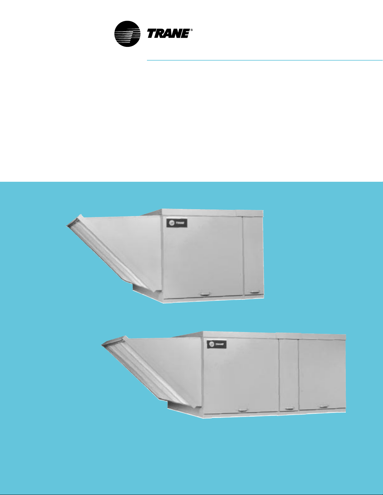
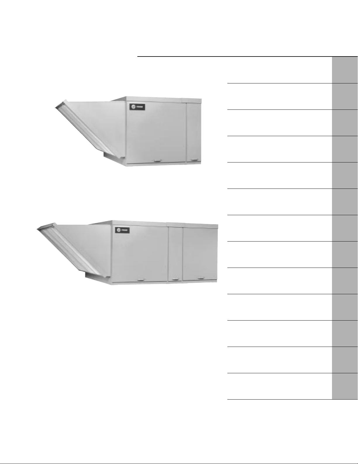
P ackaged
Air Handling
Products
For Cooling, Ventilating and
Make-Up Air Applications
Page 2

Features
and
Benefits
The Trane packaged air handling
product line is suitable for cooling,
ventilating and make-up air
applications. Unit sizes range from
1500 to 14,000 cfm (0.7-6.6 cu. m/s)
1
/2 to 1 5 hp motor capabilities.
with
Units are ETL and CSA certified to UL-
1995 standard for heating, cooling and
ventilating equipment. Units are
available in one of eight standard
arrangements. Air handling units are
suitable for commercial, institutional
and industrial applications where
external system pressure losses are as
high as three inches WC.
Arrangements are divided into two
classifications — standard and high
cfm blower types.
The standard blower unit consists of a
blower cabinet that houses the
dampers, filters and blower in one
cabinet. An optional evaporative
cooling unit with standard 8 or optional
12-inc h media may also be included.
The high cfm blower unit uses a
separate damper/filter cabinet with a Vbank filter arrangement and a blower
cabinet. An optional coil cabinet is
offered on units with a cfm range of up
to 6,300. Both standard and high cfm
blower arrangements may also include
a downturn supply air plenum, outside
air and/or return air, intake hood and a
roof curb.
All units are completely packaged, rail
mounted and wired to help assure a
smooth installation and easy start-up.
Air control options offer a similar range
of control features from manual
dampers to modulating dampers that
may include mixed air, dry bulb,
pressure sensing, enthalpy control,
DDC interface or ASHRAE Cycle control
arrangements.
Features and Benefits
ETL and CSA UL-1995 Certified.
•
Cfm ranges from 1,500 to 14,000.
•
Motor sizes up to 15 hp.
•
ODP motors with high efficiency and
•
totally enclosed options.
Draw-thru cooling coil cabinet with
•
stainless steel drain pan.
Evaporative cooling with standard 8 or
•
optional 12-inch media (203 or 305
mm).
Insulated roof curb.
•
Standard 18-gauge cabinets.
•
Standard one-inch washable filters.
•
Standard blower door safety interlock
•
switch.
Standard 24-volt circuit breaker.
•
Standard printed circuit main
•
connection board.
Wiring harnesses with stamped wire
•
numbers.
Over 40 standard air control packages.
•
©American Standard Inc. 1998
2
Page 3
Contents
Features and Benefits 2
Unit Configurations 4
Model Number Description 5
General Data 6
Performance Adjustment Factors 7
Performance Data 8
Electrical Data 14
Controls 15
Dimensional Data 17
Weights 34
Options 35
Features Summary 35
Mechanical Specifications 36
3
Page 4
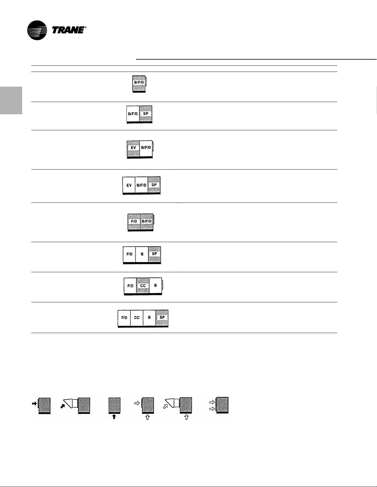
Unit Configurations
Unit T ype Standard Features
Arrangement B — — Electrical cabinet isolated from the airstream.
Air Handler with — Blower door interlock switc h with service o ver ride.
Standard Blower — Insulated Fan Section
— 1” Permanent Filters
Arrangement C — Same as Arrangement B with
Air Handler with Standard — Insulated Supply Plenum
Blower and Downflow
Supply Plenum
Arrangement D — Same as Arrangement B with
Air Handler with Standard — Evaporative Cooler
Blower and — Sealed pump motor with float valve
Evaporative Cooler — Heavy duty stainless steel water tank
— High Efficiency 8 media
— Self cleaning design
Arrangement E — Same as Arrangement D with
Air Handler with Standard — Insulated Supply Plenum
Blower, Evaporative Cooler
and Downflow
Supply Plenum
Arrangement G — — Blower door interloc k switch with service override
Air Handler with — 1” Permanent Filters
High Cfm Blower — Electrical cabinet isolated from the airstream
— Quick opening access door
— V bank filter and damper cabinet
— Fully insulated filter/damper and blower cabinet
Arrangement J — Same as Arrangement G with
Air Handler with High Cfm — Insulated Supply Plenum
Blower and Downflow
Supply Plenum
Arrangement K — Same as Arrangement G with
Air Handler with High Cfm — Coil Section
Blower and Coil Section — Mounting for 4-6 row coils
— Stainless steel drain pan with
Arrangement L — Same as Arrangement K with
Air Handler with High Cfm — Insulated Supply Plenum
Blower, Coil S ection and
Downflow Supply Plenum
Note: Motors/Air Inlet Configur ation/Air Contr ol and D amper Arrangement must be selected f or eac h unit.
Legend is as follows:
B/F/D — Standard blower/Filter/Damper
SP — Supply Plenum
EV — Evaporative Cooler
F/D — Filter/Damper
B — High cfm Blower
CC — Coil Cabinet
Air Inlet Configuration (Digit 18 of the Model Number)
1 2 3 4 5 See Note Below
Note: Horizontal outside air over return air . Specify air inlet configuration 4 or 5
and then select miscellaneous option “D” for horiz ontal return.
3
/4” tapped outlets
4
Page 5

Model Number Description
A H 0 A 20 0 A 0 D0 0 0 C F 1 0 5 H 0 P
123 45,678910,1112131415161718192021
Digit 1,2 — Unit Type
AH = Air Handling Unit
Digit 3 — Furnace T ype
0 = None
Digit 4 — Development Sequence
A = First Generation
Digit 5,6 — Unit Size
20 = 1500 - 8000 Cfm
40 = 4000 - 14000 Cfm
Digit 7 — Venting T ype
0 = None
Digit 8 — Main Pow er Supply
A = 115/60/1
B = 208/60/1
C = 230/60/1
D = 208/60/3
E = 230/60/3
F = 460/60/3
G = 575/60/3
S = Special Main Power Supply
Digit 9 — Gas Control Option
0 = No gas control option
Digit 10, 11 — Design Sequence
DO = Design Sequence
Digit 12 — Fuel Type
0 = No selection
Digit 13 — Heat Exchanger Mater ial
0 = No selection
Digit 14 — Air Handler Arrangements
B = Blower (Standard)
C = Blower (Standard) Plenum
D = Blower (Standard) Evaporative Cooler
E = Blower (Standard) Evaporative Cooler/
Plenum
G = Blower (High CFM)
J = Blower (High CFM)/Plenum
K = Blower (High CFM)/Coil Cabinet
L = Blower (High CFM)/Coil Cabinet/
Plenum
S = Special Air Handler Arrangement
Digit 15 — Motor Selection
A=1/2 HP w/contactor
B=3/4 HP w/contactor
C = 1 HP w/contactor
D=1 1/2 HP w/contactor
E = 2 HP w/contactor
F = 3 HP w/contactor
G = 5 HP w/contactor
H=1/2 HP w/magnetic starter
J=3/4 HP w/magnetic starter
K = 1 HP w/magnetic starter
L=1 1/2 HP w/magnetic star ter
N = 2 HP w/magnetic starter
P = 3 HP w/magnetic starter
Q = 5 HP w/magnetic starter
R=7 1/2 HP w/magnetic star ter
T = 10 HP w/magnetic starter
U = 15 HP w/magnetic starter
S = Special Motor
Digit 16 — Motor Speed and Starter
0 = No Selection
1 = Single Speed ODP 1800 RPM
2 = Single Speed TEFC 1800 RPM
3 = Single Speed High Efficiency ODP
1800 RPM
4 = Single Speed High Efficiency TEFC
1800 RPM
5 = 2S1W ODP 1800/900 RPM
6 = 2S2W ODP 1800/1200 RPM
S= Special Motor Speed and Starter
Digit 17 — Coil Options
0 =No cooling coil selection
A =DX coil, 4 Row, Single Circuit
B =DX coil, 4 Row, Dual Circuit
C =DX coil, 6 Row, Single Circuit
D =DX coil, 6 Row, Dual Circuit
E = Chilled Water Coil, 4 Row, Single
Circuit
G = Chilled W ater Coil, 6 R ow, Dual Circuit
S =Special coil
Digit 18 — Air Inlet Configuration
1 = Outside Air (OA) Horizontal Inlet
2 = Outside Air W/Air Hood, Horiz ontal Inlet
3 = Bottom Return Air (RA)
4 = Outside and Return Air (OA/RA)
5 = Outside and Return Air W/Air Hood
S= Special Air inlet configuration
Digit 19 — Air Contr ol and Damper
Arrangements
0 =No Selection
A =Outside Air 2 pos. Motor/ SR
B =Return Air 2 pos. Motor/ SR
C =O A/RA 2 pos SR
E = OA/RA Mod Mtr W/Mixed Air Control/
Min Pot/SR
H =OA/RA Mod Mtr W/Mixed Air Control/
SR
K =O A/RA Mod Mtr W/Min Pot/SR
M =O A/RA Mod Mtr w/Dry Bulb/Mixed Air
Control/Min Pot/SR
N = OA/RA Mod Mtr w/Enthalpy Controlled
Economizer/SR
P = OA/RA Mod Mtr W/ Space Pressure
Controller
R =O A/RA Mod Mtr W/ S-350 P
Proportional Mixed Air Control/SR
U = OA/RA MTR. W/External 0-10 VDC and
4-20 mA Analog Input/SR
(External Input)
W= ASHRAE Cycle I (OA/RA 2 pos.
w/warm-up stat/SR
X =ASHRAE Cycle II (OA/RA Mod
W/Warm-up Stat/Mixed Air/min pot/SR
Y =ASHRAE Cycle III (O A/RA Mod.
W/Warm-up Stat/Mixed Air/SR
Z = Manual Dampers
S =Special air control and damper
arrangement
Digit 20 — California Shipment
0 = Non-California Shipment
1 = California Shipment
Digit 21 — Miscellaneous Options
B =12” Evaporative Media (Celdek)
C =Moisture Eliminators
D =Horizontal Return
E = Continuous Fan Relay
F =Freezestat
H =Return Air Firestat
J =Supply Air Firestat
K =Manual Blower Switc h
N = Double Wall Construction
P = Low Leak Dampers
Q = Clogged Filter Switch
W= Interlock Relay — 24/115V Coil
SPDT10A
X =Interlock Relay — 24/115/230V Coil
DPDT 10A
Z = 8” Evaporative Media (Glasdek)
1 = 12” Evaporative Media (Glasdek)
2 = Hinged Service Access Doors
5
Page 6
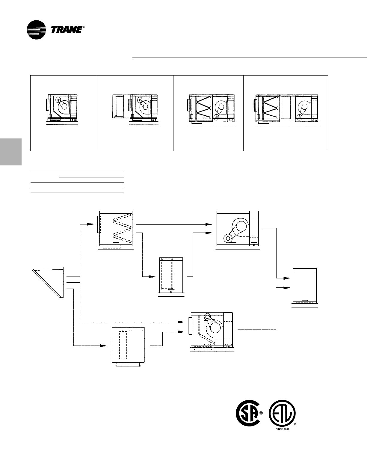
General Data
Pack aged Air Handler Arrangement Reference
Standard Blower Standard Blower W/EC-Mate High CFM Blower High CFM Blower W/Cooling
Arrang ements B, C Arrangements D , E Arrangements G, J Arrang ements K, L
Capacity 20, 40 Capacity 20, 40 Capacity 20, 40 Capacity 20, 40
20 - 1,500-6,000 CFM, 1/2-5 HP 20 - 1,500-6,000 CFM, 1/2-5 HP 20 - 3,000-8,000 CFM, 3/4-1 0 HP 20 - 3,000-4,300 CFM, 3/4-5 HP
40 - 4,000-8,000 CFM,
ESP .1-3” in WC ESP .1-3” in WC ESP .1-3” in WC ESP .1-3” in WC
Filter Data
Unit Size
Arrangement 20 40
B-E (4) 20 x 20 (6) 20 x 20
G-L (8) 20 x 20 (12) 20 x 20
1
/2-5 HP 40 - 4,000-8,000 CFM, 1/2-5 HP 40 - 5,000-14,000 CFM, 3/4-15 HP 40 - 5,000-6,300 CFM, 3/4-7 1/2 HP
Intake Hood
Damper/Filters
(High CFM)
Evaporative Cooler
(Standard)
Coil Cabinet
(High CFM)
Blower/Main Electrical
(High CFM) 0-15 HP
Dampers/Filters/Blower/Main Electrical
(Standard) 0-5 HP
Supply Plenum
6
Page 7

P erformance Adjustment Factors
Table PAF -1 — Cor r ection Factors f or Altitude
0’ 500’ 1000’ 1500’ 2000’ 2500’ 3000’ 3500’ 4000’ 4500’ 5000’ 5500’ 6000’
Temp. Barometric Pressure (In. Hg)
F 39.92 29.38 28.86 28.33 27.82 27 .31 26.82 26.32 25.84 25.36 24.9 24.43 29.98
-40 0.79 0.81 0.82 0.84 0.85 0.87 0.88 0.90 0.92 0.93 0.95 0.97 0.99
0 0.87 0.88 0.90 0.92 0.93 0.95 0.97 0.99 1.00 1.02 1.04 1.06 1.08
40 0.94 0.96 0.98 1.00 1.01 1.03 1.05 1.07 1.09 1.11 1 .13 1 .16 1.18
70 1.00 1.02 1.04 1.06 1.08 1.1 0 1.12 1.1 4 1.16 1.18 1.20 1.22 1.25
80 1.02 1.04 1.06 1.08 1.1 0 1 .12 1.1 4 1.16 1.18 1.20 1.22 1.25 1.27
100 1.06 1.08 1.1 0 1.12 1.1 4 1.16 1.18 1.20 1.22 1.25 1.27 1.29 1.32
120 1.90 1.11 1 .13 1.16 1.18 1.20 1.22 1.24 1.27 1.29 1.31 1.34 1.37
1 . Actual ESP = Duct ESP x F actor ÷ Accs. SP
2. Actual BHP = Cat. BHP ÷ Factor
3. Correct BTUH Input = Catalog BTUH Input ÷ Factor
4. Corrected BTUH Output = Corrected BTUH Input x Ef ficiency
Altitude (Feet)
Metric Conv ersion T able
Unless otherwise specified, the following conversions may be used for calculating SI unit
measurements:
1 cubic foot= 0.028 m
1 foot = 0.0305 m 1 gallon = 3.785 L
1 inch = 25.4 mm 1,000 Btu/Cu. Ft. = 37.5 MJ/m
1 psig = 6.894 kPa 1 liter/second = CFM x 0.472
1 pound = 0.453 kg 1 meter/second = FPM ¸ 196.8
1,000 Btu per hour = 0.293 kW
3
1 inch water column = 0.029 kP a
3
7
Page 8
P erformance Data
Table PD-1 — Air Handling Perf or mance Data — Arrangements B-E
Capacity CFM RPM BHP RPM BHP RPM BHP RPM BHP RPM BHP RPM BHP RPM BHP RPM BHP RPM BHP RPM BHP RPM BHP RPM BHP RPM BHP RPM BHP RPM BHP
1,500 395 0.12 530 0.19 645 0.27 750 0.35 845 0.44 930 0.54 1010 0.65 1085 0.76
2,000 435 0.22 550 0.3 655 0.4 750 0.49 835 0.59 915 0.7 995 0.81 1065 0.93 11 35 1.06
3,000 555 0.61 630 0.71 710 0.83 790 0.96 865 1.09 935 1.23 1000 1.37 1065 1.51 1125 1.66 1180 1.81 1240 1.96 1295 2.12 1350 2.28 1405 2.45 1455 2.62
20 4,000 700 1.33 750 1.47 805 1 .61 865 1.75 930 1 . 9 990 2.07 1045 2.25 11 05 2.43 1160 2.61 1210 2.8 1260 2.98 1310 3.17 1360 3.35 1405 3.54 1455 3.74
5,000 855 2.51 890 2.68 930 2.85 975 3.02 1020 3.19 1070 3.37 11 20 3.55 11 70 3.75 1220 3.96 1265 4.18 1310 4.4 1360 4.63 1400 4.86
5,500 935 3.3 965 3.49 1000 3.67 1040 3.86 1080 4.05 1120 4.24 1 165 4.43 1210 4.63 1255 4.84
6,000 10 15 4.25 1040 4.45 1075 4.65 11 05 4.85
4,000 450 0.46 565 0.64 670 0.82 760 1.0 1 845 1.22 930 1.43 1005 1.66 1075 1.9 11 40 2.15 1205 2.42
5,000 51 0 0.79 605 0.99 700 1.21 785 1.44 860 1.67 935 1 .91 1005 2.16 1070 2.42 11 35 2.69 1200 2.97
40 6,000 575 1.28 655 1.49 7 40 1.73 815 2. 885 2.28 955 2.56 1020 2.84 1085 3.12 1140 3.41 1200 3.71 1255 4.02 1315 4.34 1365 4.67 1420 5.
7,000 650 1.95 715 2.19 785 2.44 855 2.73 920 3.04 985 3.36 1045 3.68 1105 4. 11 60 4.33 1215 4.66 1270 4.99
8,000 725 2.83 780 3.1 840 3.38 905 3.67 965 3.99 1025 4.34 1080 4.71
Note: Refer to Table for Accessory Pressure Losses (Rooftop Arrangement B-E)
0.2 0.4 0.6 0.8 1 1 .2 1.4 1.6 1.8 2 2.2 2.4 2.6 2.8 3
Total External Static Pressure (Inches of Water)
Table PD-2 — Air Handling Accessory Pressure Loss Data — Arrangements B-E
Rainhood Filters Supply Evaporative Return or Outside
Capacity CFM Screen Mstr. Elim. 2” 1” 2” 1” 2” Plenum 8” 12” Damper
20 2,400 .03 .05 .09 .02 .02 .11 .06 .05 .04 .06 .05
40 4,800 .06 .09 .13 .03 .04 .18 .10 .05 .09 .13 .10
1,600 .02 .02 .05 <.01 .01 .06 .03 .02 .02 .03 .03
1,800 .02 .03 .06 <.01 .01 .07 .04 .03 .02 .03 .03
2,000 .02 .03 .07 .01 .02 .08 .04 .03 .03 .04 .04
2,200 .03 .04 .08 .01 .02 .09 .05 .04 .03 .05 .05
2,500 .04 .05 .09 .02 .03 .12 .07 .05 .04 .07 .06
3,000 .05 .07 .12 .03 .04 .16 .09 .07 .06 .10 .08
4,000 .09 .13 .17 .05 .07 .26 .16 .13 .11 .17 .15
5,000 .15 .20 .07 .1 1 .38 .23 .21 .18 .27 .23
5,500 .18 .25 .09 .1 3 .44 .28 .25 .22 .32 .28
3,200 .03 .04 .07 .01 .02 .09 .05 .02 .04 .06 .04
3,600 .04 .05 .09 .02 .02 .11 .06 .03 .05 .07 .05
4,000 .04 .06 .10 .02 .03 .13 .07 .04 .06 .09 .07
4,400 .05 .07 .11 .03 .04 .15 .09 .05 .07 .11 .08
5,000 .07 .10 .13 .03 .05 .19 .11 .06 .09 .14 .10
6,000 .10 .14 .17 .05 .07 .26 .16 .08 .14 .20 .15
7,000 .13 .19 .07 .09 .33 .21 .1 1 .18 .27 .20
8,000 .17 .24 .09 .12 .42 .26 .15 .24 .36 .26
8,500 .20 .28 .10 .14 .17 .27 .41 .30
With Throwaway Washable Pleated Air Media Air
Pressure Loss (Inches of Water)
8
Page 9

P erformance
Data
Table PD-3 — Air Handling P erfor mance Data — Arrangements G-J
Capacity CFM RPM BHP RPM BHP RPM BHP RPM BHP RPM BHP RPM BHP RPM BHP RPM BHP RPM BHP RPM BHP RPM BHP RPM BHP RPM BHP RPM BHP RPM BHP
3,000 455 0.52 495 0.6 550 0.7 610 0.82 670 0.93 730 1.06 785 1 .21 840 1.37 890 1.53 940 1.69 985 1.86 1030 2.02 1075 2.19
4,000 575 1.13 610 1 .24 645 1.35 680 1.47 720 1.61 760 1.7 6 810 1.92 855 2.07 900 2.23 940 2.4 985 2.58 1025 2.78 1070 2.99 1110 3.2 1 1 50 3.41
5,000 695 2.11 730 2.27 7 60 2.41 790 2.55 815 2.68 840 2.83 870 2.99 905 3.17 940 3.36 975 3.56 1015 3.76 1050 3.95 1085 4.15 1 1 20 4.35 1155 4.55
20 6,000 820 3.54 850 3.75 880 3.94 905 4.12 930 4.28 950 4.44 975 4.6 995 4.77 1020 4.96 1045 5.15 1070 5.36 1100 5.59 1 130 5.82 1 1 60 6.06 1190 6.3
7,000 945 5.51 975 5.78 1000 6.02 1025 6.24 1050 6.45 1070 6.64 1090 6.83 1105 7 .021125 7 .21 11 45 7.4 1 1 65 7.6 1185 7.81 1205 8.04 1225 8.28 1250 8.52
7,500 1005 6.74 1035 7 .03 1060 7.3 1085 7.54 1110 7.77 1130 7.99 1 1 50 8.19 1 1 65 8.4 11 85 8.59 1200 8.8 1215 9. 1235 9.21 1255 9.43 1270 9.66 1290 9.91
8,000 1070 8.13 1095 8.45 1125 8.74 1 145 9.01 11 70 9.27 1 1 90 9.5 1210 9.731225 9.95
5,000 405 0.67 465 0.84 540 1.03 610 1.25 675 1.5 740 1.77 800 2.04 855 2.31 905 2.59 955 2.88
6,000 470 1.08 510 1.26 570 1 .48 630 1.71 690 1.95 745 2.22 800 2.53 855 2.85 905 3.17 955 3.5
40 8,000 595 2.4 630 2.62 665 2.84 700 3.1 745 3.39 790 3.71 835 4.02 880 4.33 925 4.66 965 5.01
10,000 730 4.52 760 4.81 785 5.07 810 5.34 840 5.64 870 5.96 900 6.31 935 6.7 975 7.1 10 10 7.49 1045 7.88 1085 8.27 11 20 8.66 1 1 55 9.07 1190 9.5
12,000 860 7.64 890 8.01 915 8.35 935 8.67 960 8.99 980 9.32 1000 9.661025 10.04105010.44 108010.88 1 110 1 1.33 11 40 11.8 117012.28 120012.76 123013.23
14,000 995 1 1.97 1020 12.41 104512.83 1065 13.22 1085 13.6 1105 13.97 112014.34 114014.73
Note: Refer to T able for Accessory P ressure Losses (R oof top Arrangement G-L)
0.2 0.4 0.6 0.8 1 1 .2 1.4 1.6 1.8 2 2.2 2.4 2.6 2.8 3
T otal External Static P ressure (Inc hes of Water)
Table PD-4 — Air Handling P erfor mance Data — Arrangements K-L
Capacity CFM RPM BHP RPM BHP RPM BHP RPM BHP RPM BHP RPM BHP RPM BHP RPM BHP RPM BHP RPM BHP RPM BHP RPM BHP RPM BHP RPM BHP RPM BHP
3,000 455 0.52 495 0.6 550 0.7 610 0.82 670 0.93 730 1.06 785 1.21 840 1.37 890 1.53 940 1.69 985 1.86 1030 2.02 1075 2.19
20 4,000 575 1.13 610 1.24 645 1.35 680 1 .47 720 1 .61 760 1.7 6 810 1.92 855 2.07 900 2.23 940 2.4 985 2.58 1025 2.78 1070 2.99 1110 3.2 1 1 50 3.41
5,000 405 0.67 465 0.84 540 1.03 610 1.25 675 1. 5 740 1.77 800 2.04 855 2.31 905 2.59 955 2.88
40 6,000 470 1.08 510 1.26 570 1 .48 630 1.71 690 1 .95 745 2.22 800 2.53 855 2.85 905 3.17 955 3.5
Note: Refer to T able for Accessory Pressure Losses (Rooftop Ar rangement G-L) and Tables for Cooling Coil Data. (Roof top A r rangement K-L) Do not exceed 6,300
Cfm for units with cooling coils.
0.2 0.4 0.6 0.8 1 1 .2 1.4 1.6 1.8 2 2.2 2.4 2.6 2.8 3
T otal External Static P ressure (Inc hes of Water)
Table PD-5 — Air Handling Accessory Pressure Loss Data — Arrangements G-L
Rainhood Filters Supply Return or Outside
Capacity CFM Screen Mstr. Elim. 2” 1” 2” 1” 2” Plenum Damper
Note: Refer to T able for Cooling Coil and Table for Chilled Water Coil Pressure Losses. (Air Handler A rrangements K,L)
1,600 .02 .02 .03 <.01 <.01 .03 .01 .02 .03
1,800 .02 .03 .03 <.01 <.01 .03 .02 .03 .03
2,000 .02 .03 .04 <.01 <.0 1 .04 .02 .03 .04
2,200 .03 .04 .04 <.01 <.01 .04 .02 .04 .05
2,400 .03 .05 .05 <.01 <.01 .05 .03 .05 .05
2,500 .04 .05 .05 <.01 .0 1 .05 .03 .05 .06
20 3,000 .05 .07 .06 .01 .02 .07 .04 .07 .08
4,000 .09 .13 .09 .02 .03 .12 .07 .13 .15
5,000 .15 .20 .12 .03 .04 .17 .10 .21 .23
6,000 .21 .29 .16 .04 .06 .23 .14 .30 .33
6,500 .25 .34 .17 .05 .07 .26 .16 .35 .39
7,000 .29 .40 .19 .06 .08 .30 .18 .40 .45
7,400 .32 .45 .06 .09 .33 .20 .45 .50
3,300 .03 .04 .03 <.01 <.01 .03 .02 .03 .05
3,500 .03 .05 .03 <.01 <.01 .03 .02 .03 .05
4,000 .04 .06 .04 <.01 <.0 1 .04 .02 .04 .07
4,500 .05 .08 .05 <.01 <.01 .05 .03 .05 .08
40 5,000 .07 .10 .05 <.01 .01 .06 .03 .06 .10
6,000 .10 .14 .07 .01 .02 .08 .04 .08 .15
8,000 .17 .24 .10 .02 .03 .13 .07 .15 .26
10,000 .27 .38 .13 .03 .05 .19 .11 .23 .41
12,000 .39 .55 .17 .05 .07 .26 .16 .34 .59
14,000 .53 .75 .07 .09 .33 .21 .46 .80
With Throwaway Washable Pleated Air Air
Pressure Loss (Inches of Water)
9
Page 10

P erformance
Data
Table PD-6 — DX Cooling Coil Performance D ata (Ref . R-22) — Rooft op Arrangements K, L
Capacity based on 95 F EDB, 74 F EWB, 45 F Sat. Suction, 100 F Liquid
Unit Flow Velocity Spacing Capacity L.A.T. A.P.D. WT. Capacity L.A.T. A.P.D. WT.
Capacity (SCFM) (FPM) (FPF) (MBH) (DB/WB) In. W.C. (LBS) (MBH) (DB/WB) In. W .C. (LBS)
20 1600 217 *96 91 .1 59 / 58 0.11 84 115
40 3300 304 96 173.1 61 / 59 0.21 115 207.5 56 / 55 0.31 158
Air Face Fin 4 6
*120 99.5 56 / 56 0.12 89 1 22
2000 271 96 105.3 61 / 59 0.17 84 129.3 55 / 55 0.25 115
3000 407 96 136.1 64 / 61 0.33 84 171.4 58 / 57 0.50 115
4000 542 96 160.0 66 / 63 0.51 84 204.4 61 / 60 0.77 11 5
4400 596 96 168.6 67 / 64 0.58 84 215.7 62 / 60 0.87 11 5
4000 369 96 194.3 63 / 60 0.29 1 1 5 238.6 57 / 57 0.43 158
5000 461 96 219.9 65 / 62 0.40 1 1 5 277.9 59 / 58 0.60 158
6000 553 96 241.3 66 / 63 0.53 115 312.4 60 / 59 0.79 158
6300 581 96 247.1 67 / 63 0.56 115 321.9 61 / 60 0.84 158
144 106.4 54 / 54 0.13 95 120.8 51 / 51 0.20 130
120 117.2 58 / 57 0.18 89 138.7 53 / 53 0.27 122
144 126.6 56 / 55 0.20 95 145.3 52 / 52 0.29 130
120 154.4 61 / 59 0.36 89 186.6 56 / 56 0.54 122
144 169.8 58 / 58 0.38 95 198.1 54 / 54 0.57 130
120 184.1 63 / 61 0.55 89 224.8 58 / 58 0.82 122
144 205.2 61 / 59 0.59 95 243.3 56 / 56 0.87 130
120 194.5 64 / 62 0.63 89 238.1 59 / 59 0.94 122
144 217.7 61 / 60 0.67 95 261.2 57 / 57 1.00 130
120 191.6 58 / 57 0.22 122 224.7 54 / 54 0.33 170
144 205.9 56 / 56 0.24 130 237.6 52 / 52 0.36 182
120 216.5 60 / 58 0.31 122 260.6 55 / 55 0.46 170
144 234.1 58 / 57 0.33 130 277.7 53 / 53 0.49 182
120 246.8 62 / 60 0.43 122 306.9 56 / 56 0.65 170
144 271.9 59 / 58 0.46 130 330.3 54 / 54 0.69 182
120 273.5 63 / 61 0.56 122 348.2 58 / 57 0.85 170
144 307.7 61 / 59 0.60 130 377.9 56 / 55 0.91 182
120 281.7 64 / 62 0.60 122 359.7 58 / 57 0.91 170
144 317.7 61 / 60 0.64 130 391.3 56 / 56 0.97 182
Number of Rows
Conversions:
2119 SCFM = 1 m/s
196.8 FPM = 1 m/s
3.412 MBH = 1 kW
(F-32) 5/9 = C
1 In. W.C. = 248.8 Pa
1 LB. = 0.453 kg
Notes:
1 .) Data cer tified in accordance with ARI Standard 410.
2.) Capacity based on 95 F EDB, 74 F EWB, 45 F Sat. Suction, 100 F Liquid.
3.) Weight listed is the total weight of the dry coil.
4.) Coils denoted by an asterisk ( * ) require special pricing; consult product marketing for special coil requirements and pricing.
10
Page 11

P erformance
Data
Table PD-7 — DX Cooling Coil Performance D ata (Ref . R-22) — Rooft op Arrangements K, L
Capacity based on 80 F EDB, 67 F EWB, 45 F Sat. Suction, 100 F Liquid
Unit Flow Velocity Spacing Capacity L.A.T. A.P.D. WT. Capacity L.A.T. A.P.D. WT.
Capacity (SCFM) (FPM) (FPF) (MBH) (DB/WB) In. W.C. (LBS) (MBH) (DB/WB) In. W.C. (LBS)
20 1600 217 *96 84 1 15
40 3300 304 *96 113.2 57 / 56 0.21 1 1 5 1 58
Air Face Fin 4 6
*120 89 122
2000 271 *96 84 115
3000 407 96 88.2 59 / 58 0.33 84 112.0 56 / 55 0.50 1 15
4000 542 96 101.3 61 / 59 0.51 84 134.3 57 / 56 0.77 1 15
4400 596 96 105.6 62 / 60 0.58 84 142.1 58 / 57 0.87 1 15
4000 369 96 127.4 58 / 57 0.29 115 156.7 55 / 54 0.43 158
5000 461 96 144.9 60 / 58 0.40 115 179.0 56 / 56 0.60 158
6000 553 96 159.7 61 / 59 0.53 115 199.4 57 / 56 0.79 158
6300 581 96 163.8 61 / 59 0.56 115 205.6 58 / 57 0.84 158
*144 95 79.8 50 / 50 0.19 130
*120 89 122
144 82.2 54 / 54 0.20 95 97.7 51 / 51 0.29 130
120 97.7 58 / 57 0.36 89 123.1 54 / 54 0.53 122
144 107.5 56 / 56 0.38 95 131.8 53 / 53 0.57 130
120 116.3 59 / 58 0.54 89 149.4 55 / 55 0.82 122
144 130.5 57 / 57 0.58 95 161.7 54 / 54 0.87 130
120 123.1 60 / 58 0.62 89 158.7 56 / 55 0.94 122
144 138.6 58 / 57 0.66 95 172.3 55 / 54 1.00 130
*120 126.2 55 / 55 0.22 122 170
144 136.5 54 / 54 0.24 130 155.2 51 / 51 0.36 182
120 143.1 56 / 56 0.31 122 168.7 53 / 53 0.46 170
144 155.9 55 / 54 0.33 130 179.8 52 / 52 0.48 182
120 164.1 58 / 57 0.43 122 197.6 55 / 54 0.64 170
144 180.2 56 / 55 0.46 130 213.9 53 / 53 0.68 182
120 182.0 59 / 58 0.57 122 224.5 55 / 55 0.84 170
144 20 1.1 57 / 56 0.61 130 245.1 54 / 54 0.90 182
120 186.9 59 / 58 0.61 122 232.1 56 / 55 0.90 170
144 206.9 57 / 57 0.65 130 253.9 54 / 54 0.96 182
Number of Rows
Conversions:
2119 SCFM = 1 m/s
196.8 FPM = 1 m/s
3.412 MBH = 1 kW
(F-32) 5/9 = C
1 In. W.C. = 248.8 Pa
1 LB. = 0.453 kg
Notes:
1 .) Data cer tified in accordance with ARI Standard 410.
2.) Capacity based on 80 F EDB, 67 F EWB, 45 F Sat. Suction, 100 F Liquid.
3.) Weight listed is the total weight of the dry coil.
4.) Coils denoted by an asterisk ( * ) require special pricing; consult product marketing for special coil requirements and pricing.
Table PD-8 — Standard Conditions and Specifications — Refrigerant DX Coil
CONDITIONS
Elevation 0 Ft.
Entering Air Temperature DB: 80 F 95 F
Entering Air Temperature WB: 67 F 74 F
Suction Temperature: 45 F 45 F
Liquid Temperature: 100 F 100 F
Fouling Factor: 0 HR x FT2 x F/BTU
SPECIFICATIONS
Coil Type: DE optional DH
T ube Size:
Row Sizes: 4,6
Fin Type: Delta-Flo
Fin Size: 0.0055” Aluminum
Fin Spacing: Standard — 96, (120), 144 Fins/Ft.
Circuiting: Standard —Single
Turbulators: No
DIMENSIONAL DATA LISTING
Unit Size Finned Width Fixed Finned Length
20 30.00 34.00
40 30.00 50.00
Note:
1 . Above specification is for standard coil with standard fin spacing.
Specify fin spacing and dual circuiting.
2. Special coils — contact Product Marketing.
3. Every order requires a coil selection.
1
/2” O.D. x 0.016” TWT Copper
Optional — 72 thru 180 Fins/Ft.
Optional — Dual:
a) Intertwined
b) Face-Split
11
Page 12

Perf ormance
Data
Table PD-9 — Chilled Water Coil Performance D ata — Roof top Arrangements K, L
Capacity based on 95 F EDB, 74 F EWB, 45 EWT, 70 GPM
Unit Flow Velocity Spacing Capacity L.A.T. A.P.D. WT . Capacity L.A.T . A.P.D. WT.
Capacity (SCFM) (FPM) (FPF) (MBH) (DB/WB) In. W.C. (LBS) (MBH) (DB/WB) In. W.C. (LBS)
20 1800 254 96 109.8 58 / 56 0.12 84 131.2 52 / 52 0.18 115
40 2100 202 96 136.2 56 / 55 0.08 115 159.5 51 / 51 0.12 158
Conversions:
21 19 SCFM = 1 m/s
196.8 FPM = 1 m/s
3.412 MBH = 1 kW
(F-32) 5/9 = C
1 In. W.C. = 248.8 Pa
1 LB. = 0.453 kg
Air Face Fin 4 6
120 119.0 55 / 54 0.14 89 138.6 50 / 50 0.21 122
3000 424 96 148.1 63 / 60 0.27 84 185.5 57 / 56 0.40 115
4300 607 96 175.1 67 / 63 0.47 84 226.1 61 / 59 0.70 1 15
3500 336 96 188.4 61 / 59 0.19 115 230.8 55 / 54 0.28 158
4900 470 96 223.8 64 / 61 0.32 115 281.9 59 / 57 0.47 158
6300 605 96 250.4 67 / 63 0.46 115 321.3 61 / 60 0.68 158
144 126.3 53 / 53 0.16 95 143.9 49 / 49 0.24 130
120 163.0 60 / 58 0.31 89 199.9 55 / 54 0.46 122
144 174.9 58 / 57 0.35 95 210.8 53 / 53 0.52 130
120 195.3 64 / 61 0.52 89 247.5 58 / 57 0.78 122
144 210.8 62 / 60 0.60 95 263.2 56 / 56 0.90 130
120 146.9 54 / 53 0.09 122 167.5 49 / 49 0.14 170
144 155.0 52 / 51 0.1 1 130 172.9 48 / 48 0.16 182
120 205.7 58 / 57 0.22 122 246.5 53 / 53 0.33 170
144 219.6 56 / 55 0.25 130 258.6 51 / 51 0.37 182
120 247.4 62 / 60 0.36 122 305.8 56 / 56 0.54 170
144 265.9 60 / 58 0.41 130 323.6 55 / 54 0.61 182
120 278.8 64 / 62 0.51 122 351.4 59 / 58 0.77 170
144 300.7 62 / 61 0.59 130 373.6 57 / 57 0.89 182
Notes:
1 .) Data cer tified in accordance with ARI Standard 410.
2.) Capacity based on 95 F EDB, 74 F EWB, 45 F Sat. Suction, 100 F Liquid.
3.) Weight listed is the total weight of the dry coil.
4.) Contact product marketing for special coil requirements.
Number of Rows
Table PD-10 — Chilled Water Coil Performance D ata — Roof t op Arrangements K, L
Capacity based on 80 F EDB, 67 F EWB, 45 EWT, 70 GPM
Unit Flow Velocity Spacing Capacity L.A.T. A.P.D. WT. Capacity L.A.T. A.P.D. WT .
Capacity (SCFM) (FPM) (FPF) (MBH) (DB/WB) In. W .C. (LBS) (MBH) (DB/WB) In. W.C. (LBS)
20 1800 254 96 77.4 54 / 53 0.12 84 92.3 50 / 50 0.18 115
40 2100 202 96 95.9 53 / 52 0.08 115 112.1 49 / 49 0.12 158
Conversions:
2119 SCFM = 1 m/s
196.8 FPM = 1 m/s
3.412 MBH = 1 kW
(F-32) 5/9 = C
1 In. W.C. = 248.8 Pa
1 LB. = 0.453 kg
Air Face Fin 4 6
120 83.9 52 / 52 0.14 89 97.5 49 / 49 0.21 122
3000 424 96 104.9 58 / 56 0.27 84 131.0 53 / 53 0.40 115
4300 607 96 124.5 60 / 58 0.47 84 160.1 56 / 55 0.70 1 15
3500 336 96 133.3 56 / 55 0.19 115 162.9 52 / 52 0.28 158
4900 470 96 158.9 59 / 57 0.32 115 199.6 55 / 54 0.47 158
6300 605 96 177.7 61 / 58 0.47 1 1 5 227.4 56 / 55 0.69 158
144 89.0 51 / 50 0.16 95 1 01.2 48 / 48 0.24 130
120 115.5 56 / 55 0.31 89 141.2 52 / 51 0.47 122
144 123.7 54 / 54 0.35 95 148.6 51 / 50 0.53 130
120 138.4 58 / 57 0.53 89 174.9 54 / 54 0.79 122
144 149.2 57 / 56 0.60 95 185.9 53 / 53 0.90 130
120 103.4 51 / 51 0.09 122 11 7.7 48 / 48 0.14 170
144 109.0 50 / 49 0.11 130 121.5 47 / 47 0.16 182
120 145.5 54 / 53 0.22 122 174.0 51 / 50 0.33 170
144 155.2 53 / 52 0.25 130 182.2 49 / 49 0.37 182
120 175.2 57 / 56 0.36 122 216.1 53 / 53 0.54 170
144 188.1 55 / 55 0.41 130 228.4 52 / 52 0.61 182
120 197.5 59 / 57 0.52 122 248.5 55 / 54 0.78 170
144 212.8 57 / 56 0.59 130 263.9 54 / 53 0.89 182
Notes:
1 .) Data cer tified in accordance with ARI Standard 410.
2.) Capacity based on 80 F EDB, 67 F EWB, 45 F Sat. Suction, 100 F Liquid.
3.) Weight listed is the total weight of the dry coil.
4.) Contact product marketing for special coil requirements.
Number of Rows
12
Page 13

P erformance
Data
Table PD-11 — Standar d Conditions and Specifications — Chilled Water Coil
CONDITIONS
Elevation 0 Ft.
Entering Air Temperature DB: 80 F 95 F
Entering Air T emperature WB: 67 F 74 F
Entering Water Temperature: 45 F 45 F
Water Flow Rate: 70 GPM 70 GPM
T ube Velocity: 4 Ft./Sec.
Fouling Factor: 0 HR x FT2 x F/BTU
SPECIFICATIONS
Coil Type: W — Full Row Serpentine
T ube Size: 5/8” O.D. x 0.024” TWT Copper
Row Sizes: 4,6
Fin Type: Prima-Flo
Fin Size: 0.0075” Aluminum
Fin Spacing: Standard — 96, (120), 144 Fins/Ft.
Circuiting: Single Circuit
Drainable: Yes
T urbulators: No
DIMENSIONAL DATA LISTING
Unit Size Finned Width Fixed Finned Length
20 30.00 34.00
40 30.00 50.00
Note:
1 . Above specification is for standard coil with standard fin spacing.
2. Special coils — contact Product Marketing.
3. Every order requires a coil selection.
Optional — 80 thru 168 Fins/Ft.
Table PD-12 — Evaporative Cooling P erfor mance D ata and Pr essur e Drop — Roof t op Arrangements D,E
CFM Efficiency Efficiency 8” or 12” Deep Media in. of Water “A ” Unit Shipping Operating
Unit Size Min. Max. Min. Max. Min. Max. Ft.2 (m2) In. (mm) Min. Max. In. (mm) lb. (kg) lb. (kg)
20 1,600 5,500 77 88 88 92 9.38 31 x 43 9/16 0.03 0.20 43 3/4 166 386
40 3,200 8,500 77 86 87 92 12.92 31 x 60 0.07 0.28 60 1/4 206 509
Note:
1. These weights are for evaporative cooler only.
(cu. m/s) (cu. m/s) Range Range Face Area Size (KPa) (KPa) Width Wt. Wt.
(0.755) (2.596) (0.87) (787) (1106) (0.01) (0.05) (1 111) (75) (175)
(1.510) (4.012) (1.20) (787) (1524) (0.02) (0.07) (1530) (93) (231)
8” Saturation 12” Saturation Pressure Drop (1) (1)
Chart PD-1 — Evaporative Cooler Efficiency/A.P.D. Chart
CELdek® Evaporative Media
The Trane Evaporative Cooler uses high
efficiency CELdek
®
media. CELdek® is
made from a special cellulose paper,
impregnated with insoluble anti-rot
salts and rigidifying saturants. The cross
fluted design of the pads induces highturbulent mixing of air and water for
optimum heat and moisture transfer.
The Trane evaporative coolers are
standard with eight-inch deep media
which produce high efficiency and high
face velocities, along with a two-inch
distribution pad to disperses the water
evenly over the pads. We offer an
optional 12-inch deep media (see c har t
at right for efficiencies).
13
Page 14

Electrical Data
Air Handling Units Motor Electrical Data
Voltage 1/2 HP 3/4 HP 1 HP 1 1/2 HP 2 HP 3 HP 5 HP 7 1/2 HP 10 HP 15 HP
115/60/1 ODP 7.2 10.9 13.4 18.0 26.0 33.0 NA NA NA NA
208/60/1 ODP 4.3 6.0 6.7 9.3 11.5 16.5 NA NA NA NA
230/60/1 ODP 4.3 5.5 6.7 9.0 13.0 16.5 NA NA NA NA
208/60/3 ODP 2.8 2.6 3.2 4.8 6.2 8.4 12.2 24.0 28.0 44.9
230/60/3 ODP 2.8 2.6 3.2 4.8 6.2 8.4 12.2 21.6 26.6 40.6
460/60/3 ODP 1 .4 1.3 1.6 2.4 3.1 4.2 6.1 1 0.8 13.3 20.3
575/60/3 ODP 1 .1 1.4 1.5 1.9 2.5 3.6 5.3 8.6 10.6 15.6
1 15/60/1 TE 9.0 1 1.4 13.6 17 .6 24.6 34.0 NA NA NA NA
208/60/1 TE 3.9 4.5 6.8 8.0 12.3 17 .0 NA NA NA NA
230/60/1 TE 4.5 5.7 6.8 8.8 12.3 17 .0 NA NA NA NA
208/60/3 TE 2.1 2.8 3.4 4.8 6.4 9.4 14.0 21.8 28.7 42.6
230/60/3 TE 2.2 2.8 3.6 4.9 6.4 9.2 13.0 20.4 26.4 28.4
460/60/3 TE 1.1 1.4 1.8 2.4 3.2 4.6 6.5 10.2 13.2 19.2
575/60/3 TE 0.9 1.3 1.7 1.9 2.6 3.6 5.1 7 .6 9.6 14.4
115/60/1 HEODP 5.2 6.4 9.2 12.5 16.4 NA NA NA NA NA
208/60/1 HEODP 2.8 4.2 NA NA NA NA NA NA NA NA
230/60/1 HEODP 2.6 5.2 4.6 6.3 8.2 NA NA NA NA NA
208/60/3 HEODP 1.8 2.5 3.6 5.0 6.7 9.2 14.7 22.1 29.0 40.0
230/60/3 HEODP 1.6 2.3 2.8 3.8 5.4 8.0 12.8 19.2 25.2 36.0
460/60/3 HEODP 0.8 1 .2 1.4 1.9 2.7 4.0 6.4 9.6 25.2 18.0
575/60/3 HEODP NA NA 1.1 1.8 2.3 3.2 5.2 7.7 10.1 14.5
115/60/1 HETE 5.5 7.6 9.2 14.0 19.2 NA NA NA NA NA
208/60/1 HETE NA NA NA NA NA NA NA NA NA NA
230/60/1 HETE 2.8 3.8 4.6 7 .0 9.6 NA NA NA NA NA
208/60/3 HETE NA NA 3.2 4.6 6.2 8.8 14.7 21.4 29.0 41.2
230/60/3 HETE 4.6 6.3 3.0 4.2 5.8 8.0 12.0 18.8 25.2 37 .0
460/60/3 HETE 2.3 3.2 1.5 2..1 2.9 4.0 6.0 9.4 12.6 18.5
575/60/3 HETE NA NA 1.1 1.8 2.4 3.2 4.8 7.5 10.2 14.9
208/60/3 2S1W NA NA 3.0/1.0 4.4/1.8 6.2/3.0 9.0/3.4 15.0/6.0 21.0/7.5 29.0/9.6 NA
230/60/3 2S1W NA NA 3.0/1.0 4.4/1.8 5.9/2.9 8.0/3.3 14.0/6.2 19.5/7.5 25.0/9.3 NA
460/60/3 2S1W NA NA 1.5/0.5 2.2/1.9 3.1/1.3 3.8/1 .6 6.8/2.8 10.0/4.0 12.0/4.3 18.0/6.0
575/60/3 2S1W NA NA NA NA NA NA NA NA NA NA
115/60/1 2S2W 9.2/6.0 9.2/4.6 1 1.9/6.9 NA NA NA NA NA NA NA
208/60/1 2S2W NA 5.0/2.5 6.3/3.0 NA NA NA NA NA NA NA
230/60/1 2S2W 4.6/3.0 4.6/2.3 6.0/3.6 NA NA NA NA NA NA NA
208/60/3 2S2W 2.4/1 .6 3.0/1 .9 3.4/2.0 5.0/2.6 6.5/3.5 9.3/4.9 NA 20.0/1 1.0 27.0/14.0 NA
230/60/3 2S2W 2.1/1 .4 2.7/1.7 3.2/2.0 4.8/2.9 6.3/3.5 8.5/4.6 NA 19.0/10.0 25.0/12.5 NA
460/60/3 2S2W 1 .1/0.7 1.3/0.9 1.5/1.0 2.3/1.3 3.0/1.7 4.6/2.7 NA 9.7/5.5 12.2/7.0 NA
575/60/3 2S2W NA NA NA NA NA NA NA NA NA NA
Notes:
1. ODP = Open Drip Proof
2. TE = Totally enclosed
3. HEODP = High Efficiency Open Drip Proof
4. HETE = High Efficiency T otally Enclosed
5. 2S1W = Two Speed One Winding
6. 2S2W = Two Speed Two Winding
7. NA = Not A vailable
FLA based on NEC Ratings
14
Page 15

Controls
Air Inlet Configuration
The air inlet configuration defines the
entering air opening for the air
handling units. This selection does not
include dampers and must match the
required opening for the air control
and damper arrangement. A horiz ontal
return air feature is offered on air inlet
configurations 3 and 4.
Air Inlet Configuration
1
4
Note: Horizontal outside air over return
air. Specify air inlet configuration 4 or 5
and then select miscellaneous option
“D” for horizontal return.
Damper Options
Dampers shall be of the opposed blade
type, constructed of galvanized steel
with neoprene nylon bushings, blades
to be mechanically interloc ked.
Optional low leak outside air dampers
shall be of the opposed blade type,
construction of galvanized steel with
neoprene nylon bushings and vinyl
blade edge seals, blades to be
mechanically interloc ked.
Outside Air or Retur n Air/Two- Position
Motor/Spring Retur n
Units with outside air or return air only
shall be provided with damper, twoposition spring return damper motor
and controls. The motor shall power
the damper full open when the unit is
on and full closed when the unit is off.
2
5
3
See Note
Below
Outside Air/Return Air T w o-Position
Spring Retur n
T wo-position spring return motor with
interlocked outside and return air
dampers shall be provided. The motor
shall power either the outside air
damper full open and the return air
damper full closed or the outside air
damper full closed and the return air
damper full open in response to an
outside air temperature sensor.
(Includes an outside air thermostat that
makes on a rise in temperature and
drives the damper open.) When the unit
is off, the motor will drive the outside
air damper full closed and the return air
damper full open.
Outside Air/Return Air Modulating
Motor with Mixed Air Contr ol/
Minimum Position P otentiomet er/
Spring Retur n
Modulating motor with interlocked
outside and return air dampers shall be
provided. The motor shall modulate the
position of the outside and return air
dampers in response to a thermostatic
controller located in the mixed air
stream. Units shall also be provided
with a minimum position
potentiometer for minimum outside air
damper position.
The spring return feature drives the
outside air damper full closed and the
return air damper full open when the
unit is off.
Outside Air/Return Air Modulating
Motor with Mixed Air Temperature
Control/Spring Retur n
Modulating motor with interlocked
outside and return air dampers shall be
provided. The motor shall modulate the
position of the outside and return air
dampers in response to a thermostatic
controller located in the mixed air
stream.
The spring return feature drives the
outside air damper full closed and the
return air damper full open when the
unit is off.
Outside Air/Return Air Modulating
Motor with Minimum Position
Potentiomet er/Spr ing Retur n
Modulating motor with interlocked
outside and return air dampers shall be
provided. The motor shall position the
outside and return air dampers in
response to a manually set
potentiometer.
The spring return feature drives the
outside air damper full closed and the
return air damper full open when the
unit is off.
Outside Air/Return Air Modulating
Motor with Dry Bulb/Mixed Air
Temperature Contr ol and Minimum
Position P otentiomet er/Spr ing Retur n
Modulating motor with interlocked
outside and return air dampers shall be
provided. The motor shall modulate the
position of the outside and return air
dampers in response to a thermostatic
controller and dry bulb thermostat
located in the mixed air stream. Units
shall also be provided with a minimum
position potentiometer for minimum
outside air damper position.
The spring return feature drives the
outside air damper full open and the
return air damper full closed when the
unit is off.
Outside Air/Return Air Modulating
Motor with Enthalpy Controlled
Economizer/Spring Return
Modulating motor with spring return
and interlocked outside and return air
dampers shall be provided. The motor
shall modulate the position of the
outside and return air dampers in
response to an enthalpy controlled
economizer . When the unit is off the
motor will drive the outside air damper
full closed and the return air damper
full open.
Outside Air/Return Air Modulating
Motor with Space Pressure Contr oller
Modulating motor with spring return
and interlocked outside and return air
dampers shall be provided. The motor
shall modulate the position of the
outside and return air dampers in
response to a pressure sensor located
in the building.
15
Page 16

Controls
Outside Air/Return Air Modulating
Motor with S-350P Proportional Mix ed
Air Control/Spring Ret ur n
Modulating motor with spring return
and interlocked outside and return air
dampers shall be provided. The motor
shall modulate the position of the
outside and return air dampers in
response to a solid-state mixed air
sensor and S-350 proportional
controller. When the unit is off the
motor will drive the outside air damper
full closed and the return air damper
full open.
Outside Air/Return Air Modulating
Motor with External 4-20 mA or
0-10 VDC Analog Input/Spring Retur n
Modulating motor interlocked with
outside and return air dampers shall be
provided. The motor shall modulate the
position of the outside and return air
dampers in response to a 4-10 mA or
0-10 VDC signal supplied by an external
DDC controller.
The spring return feature drives the
outside air damper full closed and the
return air damper full open when the
unit is shut down.
ASHRAE Cycle I (Outside/Retur n Air
Two-Position with Warm-Up Stat/
Spring Retur n)
T wo-position spring return motor with
interlocked outside and return air
dampers shall be provided. The motor
shall power the outside air damper full
open after a warm-up period
determined by a minimum supply air
temperature sensor when the unit is
on, and full closed when the unit is off.
ASHRAE Cycle II (Outside Air/Return
Air Modulating Motor with Warm-Up
Stat/Mixed Air T emperatur e Controller/
Minimum Position P ot entiometer/
Spring Retur n)
Modulating motor with interlocked
outside and return air dampers shall be
provided. The motor shall modulate the
position of the outside and return air
dampers in response to a thermostatic
controller located in the mixed air
stream after a warm-up period
determined by a minimum supply air
temperature sensor. Units shall also be
provided with a minimum position
potentiometer for minimum outside air
damper position.
When the unit is off, the motor will
drive the outside air damper full closed
and the return air damper full open.
ASHRAE Cycle III (Outside Air/Return
Air Modulating Motor with Warm-Up
Thermostat/Mixed Air T emper ature
Controller/Spr ing Retur n)
Modulating motor with spring return
and interlocked outside and return air
dampers shall be provided. The motor
shall modulate the position of the
outside and return air dampers in
response to a thermostatic controller
located in the mixed airstream after a
warm-up period determined by a
minimum supply air temperature
sensor. Units shall also be provided
with a minimum position
potentiometer for minimum outside air
damper position. When the unit is of f ,
the motor will drive the outside air
damper full closed and the return air
damper full open.
Manual Dampers
Units with outside air and return air
shall be provided with manually set
outside and return air dampers.
16
Page 17

Dimensional Data
Air Intake Hood
Arrang ements B, C, D, E, G J , K, L
Unit Sizes 20, 40
DIMENSIONS ARE IN INCHES, DIMENSIONS IN
P AREN THESES ARE IN MILLIMETERS.
Model E Dimension
20 40 3/8”
40 56 7/8”
(1025)
(1445)
17
Page 18

Dimensional
Data
Over/Under Air Intak e with Hood
Arrang ements B, C, D , E, G J , K, L
Unit Sizes 20, 40
DIMENSIONS ARE IN INCHES, DIMENSIONS IN
PAREN THESES ARE IN MILLIMETERS.
Model E Dimension
20 40 3/8”
(1025)
40 56 7/8”
(1445)
18
Page 19

Dimensional
Data
Over/Under Air Intak e without Hood
Arrang ements B, C, D , E, G J , K, L
Unit Sizes 20, 40
DIMENSIONS ARE IN INCHES, DIMENSIONS IN
P AREN THESES ARE IN MILLIMETERS.
19
Page 20

Dimensional
Data
Supply Plenum Module
Arrang ement C, E, J , L
Unit Sizes 20, 40
DIMENSIONS ARE IN INCHES, DIMENSIONS IN
P AREN THESES ARE IN MILLIMETERS.
Note: The dimensions shown do not include base skid rail.
Model A J
20 43 7/8” 35”
40 60 3/8” 51”
(111 4) (889)
(1534) (1295)
20
Page 21

Model A
20 43 7/8”
40 60 3/8”
DIMENSIONS ARE IN INCHES, DIMENSIONS
IN PAREN THESES ARE IN MILLIMETERS.
(111 4)
(1534)
Dimensional
Data
Cooling Coil Module
Arrang ements K, L
Unit Sizes 20, 40
Maximum Coil Dimensions
Unit Size Cabinet Opening
20 42 1/4” (1 073)
40 58 3/4” (1492)
The coil section drain pan connection is 3/4 inc h NPT pipe thread. It is a female fit ting that just protrudes outside of the unit base
•
rail. It is located on the service side of the unit.
The drain pan is constructed of stainless steel, including the fitting. It is sloped towards the center of the pan and level across
•
the width of the unit.
P-trap required external to the unit provided by others.
•
“L” Inside Max.
Side Opening of Cooling Module
21
Page 22

Dimensional
Data
Evaporativ e Cooler Module
Arrangements D , E
Unit Sizes 20, 40
Model A
20 43 7/8”
40 60 3/8”
DIMENSIONS ARE IN INCHES, DIMENSIONS IN
P AREN THESES ARE IN MILLIMETERS.
(111 4)
(1534)
22
Page 23

Dimensional
Data
Air Handler with Standard Blower
Arrang ement B
AH0A 20, 40
DIMENSIONS ARE IN INCHES, DIMENSIONS
IN PARENTHESES ARE IN MILLIMETERS.
(Left Hand Service Access Shown)
Unit Dimensional Data
Capacity A B C G J
20 43-7/8 23-13/16 21-15/16 42-1/16 35
40 60-3/8 45-13/16 30-3/16 58-9/16 51-1/2
(1 114) (605) (557) (1068) (889)
(1534) (1 164) (767) (1487) (1308)
23
Page 24

Dimensional
Data
Air Handler with Standard Blower and Do wnflow Supply Plenum
Arrang ement C
AH0A 20, 40
DIMENSIONS ARE IN INCHES, DIMENSIONS
IN PAREN THESES ARE IN MILLIMETERS.
(Left Hand Service Access Shown)
Unit Dimensional Data
Capacity A B C G J
20 43-7/8 23-13/16 21-15/16 42-1/16 35
40 60-3/8 45-13/16 30-3/16 58-9/16 51-1/2
(1 114) (605) (557) (1068) (889)
(1534) (1 164) (767) (1487) (1308)
24
Page 25

Dimensional
Data
Air Handler with Standard Blower and Ev apor ativ e Cooler
Arrang ement D
AH0A 20, 40
DIMENSIONS ARE IN INCHES, DIMENSIONS
IN PAREN THESES ARE IN MILLIMETERS.
(Left Hand Service Access Shown)
Unit Dimensional Data
Capacity A B C J
20 43-7/8 23-13/16 21-15/16 35
40 60-3/8 45-13/16 30-3/16 51-1/2
(1 114) (605) (557) (889)
(1534) (1 164) (767) (1308)
25
Page 26

Dimensional
Data
Air Handler with Standard Blower, Evaporative Cooler and
Downflow Supply Plenum
Arrang ement E
AH0A 20, 40
DIMENSIONS ARE IN INCHES, DIMENSIONS
IN PAREN THESES ARE IN MILLIMETERS.
(Left Hand Service Access Shown)
Unit Dimensional Data
Capacity A B C J
20 43-7/8 23-13/16 21-15/16 35
40 60-3/8 45-13/16 30-3/16 51-1/2
(111 4) (605) (557) (889)
(1534) (11 64) (767) (1308)
26
Page 27

Dimensional
Data
Air Handler with High Cfm Blower
Arrang ement G
AH0A 20, 40
DIMENSIONS ARE IN INCHES, DIMENSIONS
IN PARENTHESES ARE IN MILLIMETERS.
(Left Hand Service Access Shown)
Unit Dimensional Data
Capacity A B C G J
20 43-7/8 23-13/16 21-15/16 42-1/16 35
40 60-3/8 45-13/16 30-3/16 58-9/16 51-1/2
(1 114) (605) (557) (1068) (889)
(1534) (1 164) (767) (1487) (1308)
27
Page 28

Dimensional
Data
Air Handler with High Cfm Blower and Downflo w Supply Plenum
Arrang ement J
AH0A 20, 40
DIMENSIONS ARE IN INCHES, DIMENSIONS
IN PAREN THESES ARE IN MILLIMETERS.
(Left Hand Service Access Shown)
Unit Dimensional Data
Capacity A B C G J
20 43-7/8 23-13/16 21-15/16 42-1/16 35
40 60-3/8 45-13/16 30-3/16 58-9/16 51-1/2
(111 4) (605) (557) (1068) (889)
(1534) (1 164) (767) (1487) (1308)
28
Page 29

Dimensional
Data
Air Handler with High Cfm Blower and Cooling Coil Section
Arrang ement K
AH0A 20, 40
DIMENSIONS ARE IN INCHES, DIMENSIONS
IN PAREN THESES ARE IN MILLIMETERS.
(Left Hand Service Access Shown)
Unit Dimensional Data
Capacity A B C G J
20 43-7/8 23-13/16 21-15/16 42-1/16 35
40 60-3/8 45-13/16 30-3/16 58-9/16 51-1/2
(1 114) (605) (557) (1068) (889)
(1534) (1 164) (767) (1487) (1308)
29
Page 30

Dimensional
Data
Air Handler with High Cfm Blower, Cooling Coil Section and
Downflow Supply Plenum
Arrang ement L
AH0A 20, 40
DIMENSIONS ARE IN INCHES, DIMENSIONS
IN PAREN THESES ARE IN MILLIMETERS.
(Left Hand Service Access Shown)
Unit Dimensional Data
Capacity A B C G J
20 43-7/8 23-13/16 21-15/16 42-1/16 35
40 60-3/8 45-13/16 30-3/16 58-9/16 51-1/2
(111 4) (605) (557) (1068) (889)
(1534) (1 164) (767) (1487) (1308)
30
Page 31

Dimensional
Data
Roof Curb— Air Handler
Arrangements B-L
20, 40
Capacity Rooftop
(CA) Arr. (RA) F G H J Q R
20 or 40 G 38-1/8 N/A 81-7/16 77-11/16 79-5/16 86-11/16
B,D N/A N/A 45-1/4 41-1/2 43-1/8 50-1/2
C,E 29-5/8 8-1/8 71-1/8 67-3/8 69 76-3/8
(752) (206) (1,806) (1,711) (1,753) (1,940)
(968) (2,069) (1,973) (2,015) (2,202)
J,K 37-3/16 29-3/16 107-5/16 103-9/16 105-3/16 112-9/16
(944) (7 41) (2,726) (2,630) (2,672) (2,859)
L37-1/8 55-1/4 133-1/4 129-1/2 131-1/8 138-1/2
(943) (1,403) (3,385) (3,289) (3,331) (3,518)
(1,149) (1,054) (1,095) (1,283)
Capacity
Arr. (CA) W B C
All (951) (1,046) (1,179)
20 37-7/16 41-3/16 46-7/16
40 53-15/16 57-11/16 62-15/16
(1,370) (1,465) (1,599)
DIMENSIONS ARE IN INCHES, DIMENSIONS
IN PARENTHESES ARE IN MILLIMETERS.
1 . R oof curbs ship knoc ked
down for full assembly.
2. Arrangement D and E
require a separate platform
for the evaporative cooler.
See separate drawing for
dimensional information
on the platform.
Model D E
20 35 37
(889) (940)
40 51-1/2 53-1/2
(1,308) (1,359)
SECTION Y -Y
SECTION X-X
31
Page 32

Dimensional
Data
Roof Openings —Air Handler
Arrangements B-L
20,40
➀ Roof Mounting Angle
➁ Curb End Rail Channel
➂ Screw - #10 x 5/8 Lg. Pan Hd. Type “AB”8 Req’d .
➃ Fasteners by Others
Blower/Filter/Damper or Filt er/D amper Area
Capacity (CA) B
20 4
40 5
➀ Curb Cross Brace Channel
➁ Curb Side Rail Channel
➂ Curb End Rail Channel
➃ Screw - #10 x 5/8 Lg. Pan Hd. Type “AB” 8 Req’d.
Curb Specifications
*Roof Openings
Supply Plenum Ar ea
Arrg, Cap. A
C,E 20,40 18-7/8
J 20,40 19-1/8
L 20,40 19-1/8
Capacity Dimension “B”
20 37.00 (940)
*All dimensions shown have been calculated to include a
one (1) inch clearance around return and supply ducts.
** Blower
Arrg. CA Std HI Coil Supply A
C,E 20
J 20
L 20
**Arrangements B, D, G, K, are without a supply plenum;
RA - Rooftop arrangement.
40 53.50 (1,359)
Ö
or 40 (631)
or 40 (1551)
or 40 (2211)
use the same return air dimensions for these unit roftop
openings. Refer to unit submittals for more detail.
Capacity (CA) D B
20 35 14
40 51-1/2 16
Unit Type AH
Ö
ÖÖ
24.859
Ö
61 .047
Ö
87.035
Ö
32
DIMENSIONS ARE IN INCHES, DIMENSIONS
IN PAREN THESES ARE IN MILLIMETERS.
Page 33

Dimensional
Data
Evaporative Cooler
Curb/Platform 20, 40
Curb Cap End Adaptor Supplied with the Unit
(one each end)
Unit/Curb End Rail Assembly
Unit/Base Rail Assembly
See View A
View A
T yp. (8) PLC’s.
➀ Evaporative Cooler Assembly
➁ Curb
➂1/4-20 “KEPS” Nut (8) R equired
➃1/4-20 x 5/8 Lg. Hex Hd. Bolt (8) Required
Evaporative Cooler Curb/Platf orm Mounting Assembly
33
Page 34

Weights
Table W -1 — Shipping Weights
Unit Size
Arrangement Net Ship Net Ship
B 406 408 529 621
C 509 616 649 767
D 612 725 785 909
E 715 852 905 920
G 567 680 7 64 888
J 649 786 913 928
K 652 789 865 880
L 734 896 1014 1 191
Metric Conversion — 1 lb = 0.453 kg.
Table W -4 — Mot or Weights
Voltage
115/60/1 ODP 20 25 25 40 42 80 NA NA NA NA
208/60/1 ODP 21 27 25 40 66 80 NA NA NA NA
230/60/1 ODP 21 25 25 40 42 80 NA NA NA NA
208/60/3 ODP 20 24 31 29 35 47 49 99 1 1 8 152
230/60/3 ODP 20 24 31 29 35 47 49 99 1 1 8 150
460/60/3 ODP 20 24 31 29 35 47 49 99 1 1 8 150
575/60/3 ODP 20 20 27 31 37 56 73 105 1 16 150
1 15/60/1 TE 26 30 34 41 65 74 NA NA NA NA
208/60/1 TE 27 36 39 48 65 74 NA NA NA NA
230/60/1 TE 26 30 34 41 65 74 NA NA NA NA
208/60/3 TE 18 23 28 32 36 55 65 90 123 295
230/60/3 TE 18 23 28 32 36 55 65 90 123 295
460/60/3 TE 18 23 28 32 36 55 65 90 123 295
575/60/3 TE 21 21 26 36 40 90 92 161 199 284
115/60/1 HEODP 32 33 38 58 72 NA NA NA NA NA
208/60/1 HEODP 32 30 NA NA NA NA NA NA NA NA
230/60/1 HEODP 32 33 38 58 72 NA NA NA NA NA
208/60/3 HEODP 22 25 40 44 44 83 89 139 141 213
230/60/3 HEODP 24 26 40 43 44 80 91 137 138 238
460/60/3 HEODP 24 26 40 43 44 80 91 137 138 238
575/60/3 HEODP NA NA 41 44 45 90 100 170 141 215
115/60/1 HETE 28 37 38 41 53 NA NA NA NA NA
208/60/1 HETE NA NA NA NA NA NA NA NA NA NA
230/60/1 HETE 28 37 38 41 53 NA NA NA NA NA
208/60/3 HETE NA NA 39 34 48 71 78 107 124 225
230/60/3 HETE 32 52 39 34 48 94 11 0 158 166 294
460/60/3 HETE 32 52 39 34 48 94 11 0 158 166 294
575/60/3 HETE NA NA 44 69 88 76 80 132 140 260
208/60/3 2S1W NA NA 34 38 48 66 81 125 143 NA
230/60/3 2S1W NA NA 34 38 48 66 81 125 143 NA
460/60/3 2S1W NA NA 34 38 41 58 94 125 136 218
575/60/3 2S1W NA NA NA NA NA NA NA NA NA NA
115/60/1 2S2W 23 30 37 NA NA NA NA NA NA NA
208/60/1 2S2W NA 29 36 NA NA NA NA NA NA NA
230/60/1 2S2W 23 29 36 NA NA NA NA NA NA NA
208/60/3 2S2W 27 32 44 47 67 84 NA 221 192 NA
230/60/3 2S2W 26 32 44 47 67 84 NA 221 192 NA
460/60/3 2S2W 26 33 40 44 55 67 NA 214 230 NA
575/60/3 2S2W NA NA NA NA NA NA NA NA NA NA
Notes:
1. ODP = Open Drip P roof
2. TE = Totally enclosed
3. HEODP = High Efficiency Open Drip Proof
4. HETE = High Efficiency T otally Enclosed
5. 2S1W = Two Speed One Winding
6. 2S2W = Two Speed Two Winding
7. NA = Not A vailable
8. Metric Conversion — 1 lb = 0.453 kg.
FLA based on NEC Ratings
20 40
1
/2 HP
3
/4 HP 1 HP 1 1/2 HP 2 HP 3 HP 5 HP 7 1/2 HP 10 HP 15 HP
Table W-2 — Roof Curb W eights
Unit Size
Arrangement 20 40
B 85 1 1 2
C133161
D 85 112
E133161
G140168
J 179 207
K 177 204
L 210 238
Outside Air Hood 51 63
Metric Conversion — 1 lb = 0.453 kg.
Table W-3 — Evaporative Cooler Weights
Unit Size lb. (Kg) lb. (Kg)
20 166 386
40 206 509
Metric Conversion — 1 lb = 0.453 kg.
Shipping Wt. Operating Wt.
34
Page 35

Options
Remote Control Station
(Order No. 134-0201 -01)
Wall mounted
•
Six LED status lamps
•
System on/off, fan auto/on, heat auto/
•
off, cool auto/of f , auxiliary on/off
switching and modulating damper
potentiometer mounting.
Plug-in terminal block wiring and wall
•
mounting bracket.
6 1/4” W x 3 3/4” H x 1 1/2” D
•
Seven-Day Timeclock
(Order No. 134-0201 -02)
Single pole double throw (SPDT) relay
•
output at setpoint time
Maximum of six setpoints per day
•
7 3/4” H x 5” W x 3 7/16” D
•
24-Hour Timeclock
(Order No. 134-0201 -03)
Single pole double throw (SPDT) relay
•
output at setpoint time.
Maximum 12 setpoints per day .
•
7 3/4” H x 5” W x 3 7/16” D
•
Roof Curbs
Roof curbs are available for all Trane
packaged air handlers offered in this
catalog. All curbs are shipped knoc ked
down for field assembly. Curbs are
normally available on a short lead time
basis so that they may be on the
jobsite well in advance of the units.
Curbs are 12 inches high, factoring in
the four -inc h unit base rail, o verall
height to the bottom of the rooftop
unit is actually 16 inches. R oof curbs
can be supplied with one-inch
fiberglass insulation.
Features Summary
T rane roof top pac kaged air handlers
have the following design features:
ETL and CSA UL-1995 certified.
•
Units are completely wired, tested and
•
rail-mounted with blower drives preset.
Draw-thru cooling coil cabinet
•
arrangements with stainless steel drain
pan.
Evaporative cooling arrangement with
•
standard 8 or optional 12-inch media
(203 or 305 mm).
35
Page 36

Mec hanical Specifications
Arr angements B-L
General
Units shall be completely factory
assembled, wired and test fired. Units
shall be mounted on metal rails with
lifting and anchor holes and shall be
suitable for slab or curb mounting. All
units shall be ETL or UL certified for
electrical safety in compliance with UL
1995 safety standard for heating,
ventilating and cooling equipment.
Electrical
Standard control relays shall be socket
mounted with terminal block
connections. All control wiring shall
terminate at terminal strips (single
point connection) and include an
identifying marker corresponding to
the wiring diagram. Motor and control
wiring shall be harnessed with terminal
block connections.
Casing
Casings shall be die-formed, 18-gauge
galvanized steel and finished in air-dry
enamel. Service and access panels
shall be provided through easily
removable side access panels with
captive fasteners. Fan sections and
supply plenums (when provided) shall
be insulated with fire resistant,
odorless, matte-faced one-inch glass
fiber material. Outside air hoods, when
provided, ship with a wire mesh inlet
screen.
Evaporativ e Cooler (Standard on
Arrang ement D and E only)
An evaporative cooler with 8-inch
media shall be provided. The
evaporative cooler shall be of a selfcleaning design with a stainless steel
water tank, regulated water flow and
overflow protection. The cooler shall
have a cabinet assembly of heavygauge aluminized steel with
weatherproof finish, a UL recognized
thermally protected sealed
recirculating pump motor, two-inc h
distribution pad, and corrosion
resistant PVC water distribution tubes.
Cooling Coil Section (Standard on
Arrang ement K and L only)
A cooling coil section, constructed of
galvanized steel, shall be provided with
the unit. This section shall be insulated
with fire resistant, odorless, mattefaced one-inch glass fiber material.
Fans
Centrifugal fan shall be belt-driven,
forward curved with double inlet,
statically and dynamically balanced.
The blower wheel shall be fixed on a
keyed shaft, supported with rubber
grommet on bearing only and ball
bearing secured. 7
1
/2 through 15 hp
motors are equipped with a pillow
block bearing assembly on the drive
side. An access interloc k switc h shall be
installed in the blower compartment
and will disengage the blower upon
removing the service panel. An
override shall be incorporated into the
interlock switc h for serviceability.
Filters
Filter rack shall be constructed of
galvanized steel with access through
the side service panel. Standard filters
are one-inch permanent washable type
(Arrangement B-E).
OR
Filter rack shall be of v-bank design for
minimal pressure drop and be
constructed of galvanized steel with
access through the side service panel.
Standard filters are one-inch
permanent washable type
(Arrangement G-L).
Electrical Cabinet
Electrical cabinet shall be isolated from
the airstream with a non-removable
access panel interior to the outer
service panel. There is provision in this
cabinet for component mounting, wire
routing and high voltage isolation.
Motor and control wiring shall be
harnessed with terminal block
connections.
Controls
All rooftop units shall be provided with
a low voltage circuit breaker rated for
150 percent of the units normal 24-volt
operating load.
Factory Installed Options
Motors — General
All motors shall be ball bearing type
with resilient base mount and NEMA
frame sizes from 48 to 256T. Windings
are Class “B”, 1800 rpm with service
factors of
1
/2 - 3/4 hp = 1.25 and 1 - 15 hp
= 1 .15.
Single-Speed Open Drip-proof
60 HZ/1800 RPM
Single-Phase (with contactor) —
Optional 115V , 208V and 230V motors
available in
1
/2 - 2 hp models.
Three-Phase (with contactor) —
Optional 208V , 230V and 460V motors
available in
1
/2 - 5 hp models.
Single-Phase (with magnetic starter) —
Optional 115V , 208V and 230V motors
available in
1
/2 - 3 hp models.
Three-Phase (with magnetic starter) —
Optional 208V , 230V, 460V and 575V
motors available in
1
/2 - 1 5 hp models.
Single-Speed TEFC
60HZ/1800 RPM
Single-Phase (with contactor) —
Optional 115V , 208V and 230V motors
available in
1
/2 - 1 1/2 hp models.
Single-Phase (with magnetic starter) —
Optional 115V , 208V and 230V motors
available in
1
/2 - 3 hp models.
Three-Phase (with magnetic starter) —
Optional 208V , 230V, 460V and 575V
motors available in
1
/2 - 1 5 hp models.
Single-Speed High Efficiency ODP
60 HZ/1800 RPM
Single-Phase (with contactor) —
Optional 115V and 230V motors
available in
208V motors available in
1
/2 - 1 hp models. Optional
1
/2 - 3/4 hp
models.
Single-Phase (with magnetic starter) —
Optional 115V and 230V motors
available in
208V motors available in
1
/2 - 2 hp models. Optional
1
/2 - 3/4 hp
models.
Three-Phase (with magnetic starter) —
Optional 208V , 230V and 460V motors
available in
1
/2 -1 5 hp models. Optional
575V motors available in 1 - 15 hp
models.
36
Page 37

Mec hanical
Specifications
Single-Speed High Efficiency TEFC
60 HZ/1800RPM
Single-Phase (with contactor) —
Optional 115V and 230V motors
available in
Single-Phase (with magnetic starter) —
Optional 115V and 230V motors
available in
Three-Phase (with magnetic starter) —
Optional 230V and 460V motors
available in
208V and 575V available in 1 - 15 hp
models.
T wo-Speed/One Winding Motors
(Three-Phase Only)
60 HZ/1800/900 RPM
Three-Phase (with magnetic starter) —
Optional 208V , 230V and 460V motors
available in 1 - 15 hp models.
T wo-Speed/Two Winding Motors
60 HZ/1800/1200 RPM
Single-Phase (with magnetic starter) —
Optional 115V and 230V motors
available in
208V motors available in 3/4 - 1 hp
models.
Three-Phase (with magnetic starter) —
Optional 208V and 230V motors
available in
460V motors available in 1/2 - 3 hp and
1
/2 - 10 hp models. Optional 575V
7
motors available in 7
Manual Blower Switch
Manual blower switch shall be factory
installed in the electrical cabinet.
DX or Chilled Water Cooling Coils
Available on arrangement K and L only.
A direct expansion (DX) or chilled
water coil certified by ARI shall be
provided with the unit.
Damper Options
Dampers shall be of the opposed blade
type, constructed of galvanized steel
with neoprene nylon bushings, blades
to be mechanically interloc ked.
Optional low leak outside air dampers
shall be of the opposed blade type,
construction of galvanized steel with
neoprene nylon bushings and vinyl
blade edge seals, blades to be
mechanically interloc ked.
1
/2 - 1 1/2 hp models.
1
/2 - 2 hp models.
1
/2 - 1 5 hp models. Optional
1
/2 - 1 hp models. Optional
1
/2 - 1 5 hp models. Optional
1
/2 - 10 hp models.
Outside Air or Return Air/ T wo- P osition
Motor/ Spring Return
Units with outside air or return air only
shall be provided with damper, twoposition spring return damper motor
and controls. The motor shall power the
damper full open when the unit is on
and full closed when the unit is off.
OA/RA T wo-P osition Spring R eturn
T wo-position spring return motor with
interlocked outside and return air
dampers shall be provided. The motor
shall power either the outside air
damper full open and the return air
damper full closed or the outside air
damper full closed and the return air
damper full open in response to an
outside air temperature sensor.
(Includes an outside air thermostat that
makes on a rise in temperature and
drives the damper open.) When the
unit is off, the motor will drive the
outside air damper full closed and the
return air damper full open.
OA/RA Mod Motor with Mixed Air
Control/Min. Pot/Spring Return
Modulating motor with interlocked
outside and return air dampers shall be
provided. The motor shall modulate the
position of the outside and return air
dampers in response to a thermostatic
controller located in the mixed air
stream. Units shall also be provided
with a minimum position
potentiometer for minimum outside air
damper position.
The spring return feature drives the
outside air damper full closed and the
return air damper full open when the
unit is off.
OA/RA Mod Motor with Mixed Air
Control/Spring Return
Modulating motor with interlocked
outside and return air dampers shall be
provided. The motor shall modulate the
position of the outside and return air
dampers in response to a thermostatic
controller located in the mixed air
stream.
The spring return feature drives the
outside air damper full closed and the
return air damper full open when the
unit is off.
OA/RA Mod Motor with Min P ot/
Spring Return
Modulating motor with interlocked
outside and return air dampers shall be
provided. The motor shall position the
outside and return air dampers in
response to a manually set
potentiometer.
The spring return feature drives the
outside air damper full closed and the
return air damper full open when the
unit is off.
OA/RA Mod Motor with Dry Bulb/
Mixed Air Control/Min Pot/
Spring Return
Modulating motor with interlocked
outside and return air dampers shall be
provided. The motor shall modulate the
position of the outside and return air
dampers in response to a thermostatic
controller and dry bulb thermostat
located in the mixed airstream. Units
shall also be provided with a minimum
position potentiometer for minimum
outside air damper position.
The spring return feature drives the
outside air damper full open and the
return air damper full closed when the
unit is off.
OA/RA Mod Motor with Enthalpy
Controlled Economizer/Spring Return
Modulating motor with spring return
and interlocked outside and return air
dampers shall be provided. The motor
shall modulate the position of the
outside and return air dampers in
response to an enthalpy controlled
economizer . When the unit is off, the
motor will drive the outside air damper
full closed and the return air damper
full open.
OA/RA Mod Motor with Space
Pressure Controller
Modulating motor with spring return
and interlocked outside and return air
dampers shall be provided. The motor
shall modulate the position of the
outside and return air dampers in
response to a pressure sensor located
in the building.
37
Page 38

Mec hanical
Specifications
OA/RA Mod Mtr with S-350P
Proportional Mixed Air Control/
Spring Return
Modulating motor with spring return
and interlocked outside and return air
dampers shall be provided. The motor
shall modulate the position of the
outside and return air dampers in
response to a solid-state mixed air
sensor and S-350 Proportional
controller. When the unit is off, the
motor will drive the outside air damper
full closed and the return air damper
full open.
OA/RA Mtr . with External 4-20 mA or 010 VDC Analog Input/Spring Return
Modulating motor interlocked with
outside and return air dampers shall be
provided. The motor shall modulate the
position of the outside and return air
dampers in response to a 4-10 mA or 010 VDC signal supplied by an external
DDC controller.
The spring return feature drives the
outside air damper full closed and the
return air damper full open when the
unit is shut down.
ASHRAE Cycle I (OA/RA Two- Position
with Warm-up Stat/SR)
T wo-position spring return motor with
interlocked outside and return air
dampers shall be provided. The motor
shall power the outside air damper full
open after a warm-up period
determined by a minimum supply air
temperature sensor when the unit is
on, and full closed when the unit is off.
ASHRAE Cycle II OA/RA Mod with
Warm-up Stat/Mixed Air/Min P ot/
Spring Return
Modulating motor with interlocked
outside and return air dampers shall be
provided. The motor shall modulate the
position of the outside and return air
dampers in response to a thermostatic
controller located in the mixed air
stream after a warm-up period
determined by a minimum supply air
temperature sensor. Units shall also be
provided with a minimum position
potentiometer for minimum outside air
damper position. When the unit is of f ,
the motor will drive the outside air
damper full closed and the return air
damper full open.
ASHRAE Cycle III O A/RA Mod. with
Warm-up Stat/Mixed Air/SR
Modulating motor with spring return
and interlocked outside and return air
dampers shall be provided. The motor
shall modulate the position of the
outside and return air dampers in
response to a thermostatic controller
located in the mixed airstream after a
warm-up period determined by a
minimum supply air temperature
sensor. When the unit is off, the motor
will drive the outside air damper full
closed and the return air damper full
open.
Manual Dampers
Units with outside air and return air
shall be provided with manually set
outside and return air dampers.
Additional Factory Installed Options
Firestat
If temperature reaches the setpoint, the
dampers will return to their normal
position and shut down the blower.
Manual reset.
Return Air Mounted (setpoint typically
130 F)
Supply Air Mounted (setpoint typically
150 F)
Freezestat
Unit shall be provided with a freezestat
(0-100 F) with the sensing bulb located
in the discharge airstream. Wired as an
interlock to prevent cold air disc harge.
12-inc h Evaporative Media
12-inc h media shall be provided for the
evaporative cooler.
Double Wall Construction
The construction will consist of a 24gauge inner liner wall with 1 -inc h 1½
lb. density insulation. Access doors on
the specified side will be hinged and of
the same double wall design. Double
wall is not available on the applicable
evaporative cooler and furnace
sections. Double wall construction will
be provided by the manufacturer on
applicable filter/damper, blower , coil
and plenum cabinets.
Clogged Filter Switch
A clogged filter pressure switch with
adjustable operating range and
normally open switch shall be installed
to sense increased suction pressure by
the blower due to filter obstruction.
Provision for remote indication shall be
provided by terminal block connection
points. Includes a status lamp mounted
in the electrical cabinet.
Moisture Eliminators
Provided in place of an inlet screen on
the outside air hood. Includes a
pressure switch.
Horizontal Return
Unit shall be supplied with the return
air opening at or under the outside air
opening location depending on the air
inlet configuration.
Continuous Fan Relay — 24V Coil
DPDT 10A
Relay provided with 24-volt coil and
double pole double-throw 10-amp
contacts. Plugs into the main
connection PC board in the electrical
cabinet. Included as standard on
Arrangement D and E. May also be
utilized as an exhaust fan interlock.
Interlock Relay — 24/115V Coil SPDT
10A
Relay has a selectable coil voltage of 24
or 115 volts and single-pole double
throw 10-amp contacts with LED on
indicator lamp. Relay is utilized as an
auxiliary relay.
Interlock Relay — 24/115-230V Coil
DPDT 10A
Relay has a selectable coil voltage of
24, 115 or 230-volts and double pole
double throw 10-amp contacts. Utilized
as an auxiliary relay for general
purpose duty.
Ambient Lockout
Airflow proving switch
Hinged Service Access Doors
Optional hinged doors are mounted to
the access side of the standard blower/
filter/damper cabinet and high CFM
filter/damper and blower cabinets in
leau of the standard removable access
doors. The hinged doors include dual
quick opening tool-less latc hes and full
perimeter gasketing to assure a water
tight seal and door stops to guard
against closure while open. The
remaining Duct Furnace(s), supply
plenum cabinets (if applicable) are
supplied with a standard removable
door. The coil cabinet door utilizes a
special removable vertical split door
allowing for coil access and unit
penetration for coil connections.
38
Page 39

Mec hanical
Specifications
Field Installed Accessories
Remote Control Station
Wall mounted. P rovides six LED status
lamps with System On/Off, F an Auto/
On, Heat Auto/Off , CoolAuto/Of f ,
Auxiliary On/Off switc hing and
modulating damper potentiometer
mounting. Designed for easy
installation with plug-in terminal block
wiring and wall mounting bracket.
(Auxiliary On/Off may be used with
the evaporative cooler fill and drain
kit)
Seven-Day Timeclock
Provides single-pole double-throw
(SPDT) relay output at setpoint time
with maximum six setpoints per day.
24-Hour Timeclock
Provides single-pole double-throw
(SPDT) relay output at setting time
with maximum 12 setpoints per day .
Disconnect Switch
115V Convenience Outlet
GFI (Ground Fault Convenience
Outlet) is manual reset with
weatherproof enclosure. (Requires
separate 115V power supplied.)
Roof Mounting Curb
Insulated roof curb shall be shipped
unassembled with hardware package
and gasket attac hed. Curb and rail
shall total 16 inches high and supplied
with a cross-member which allows
the isolation of the return and supply
air streams (when supplied).
Evaporative Cooler Platform
Provides mounting support for
evaporative cooler only.
Fill and Drain Kit
Includes three-way valve and relay for
automatic fill and drain for the
evaporative coolers. Optional
freezestat provides automatic shutof f
and drain upon meeting outside air
setpoint.
Optional Filters (One-inch permanent
standard)
T wo-inc h P ermanent
Two-inch Throwaway
One-inch 30 percent Pleated Media
T wo-inc h 30 percent Pleated Media
Thermostats
Low voltage room thermostat, singlestage with fan auto-on-switch and
system heat-off cool switc h
Low voltage room thermostat, singlestage with fan auto-on switch
Low voltage room thermostat, twostage with fan auto-on switch and
system off-heat-auto-cool switch
Low voltage programmable room
thermostat, two-stage with LCD
display, fan auto-switc h an system of fheat-auto-cool switch
Universal tamperproof guard for all
room thermostats
Low voltage duct thermostat, singlestage
Low voltage duct thermostat, twostage
Room thermostat, electronic
modulating control
Duct thermostat, electronic modulating
control
Duct thermostat, electronic modulating
control with override room thermostat
Evapor ative Cooler
General
An evaporative cooler with eight-inch
media shall be provided. The
evaporative cooler shall be of a selfcleaning design with a stainless steel
water tank, regulated water flow and
overflow protection. The cooler shall
have a cabinet assembly of heavygauge aluminized steel with
weatherproof finish, a UL recognized,
thermally protected sealed
recirculating pump motor, two-inc h
distribution pad, and corrosion
resistant PVC water distribution tubes.
Factory Installed Options
12-Inc h Evaporative Media
12-inc h media shall be provided for the
evaporative cooler.
Field Installed Accessor ies
Evaporative Cooler Platform
Provides mounting support for
evaporative cooler only
Fill and Drain Kit
Includes three-way valve and relay and
automatic fill and drain for the
evaporative cooler.
Freezestat
Freezestat provides automatic shutof f
and drain upon meeting outside air
setpoint.
39
Page 40

The T rane Company
2701 Wilma Rudolph Blvd.
Clarksville, TN 37040
www.trane.com
An American Standard Company
The T rane Company has a policy of continuous
product and product data improvement, it
reserves the right to change product design and
specifications without notice.
Library Product Literature
Product Section Air Handling
Product Mak e-Up Air
Model 000
Literature Type Data Sales Catalog
Sequence 4
Date February 1 998
File No. PL -AH-MU A-000-DS-4-298
Supersedes MUA -DS-4 695
Ordering No. MUA-DS-4
 Loading...