

Page 1

Assembly Instructions BBQ400
DOC035 REV C
Page 2

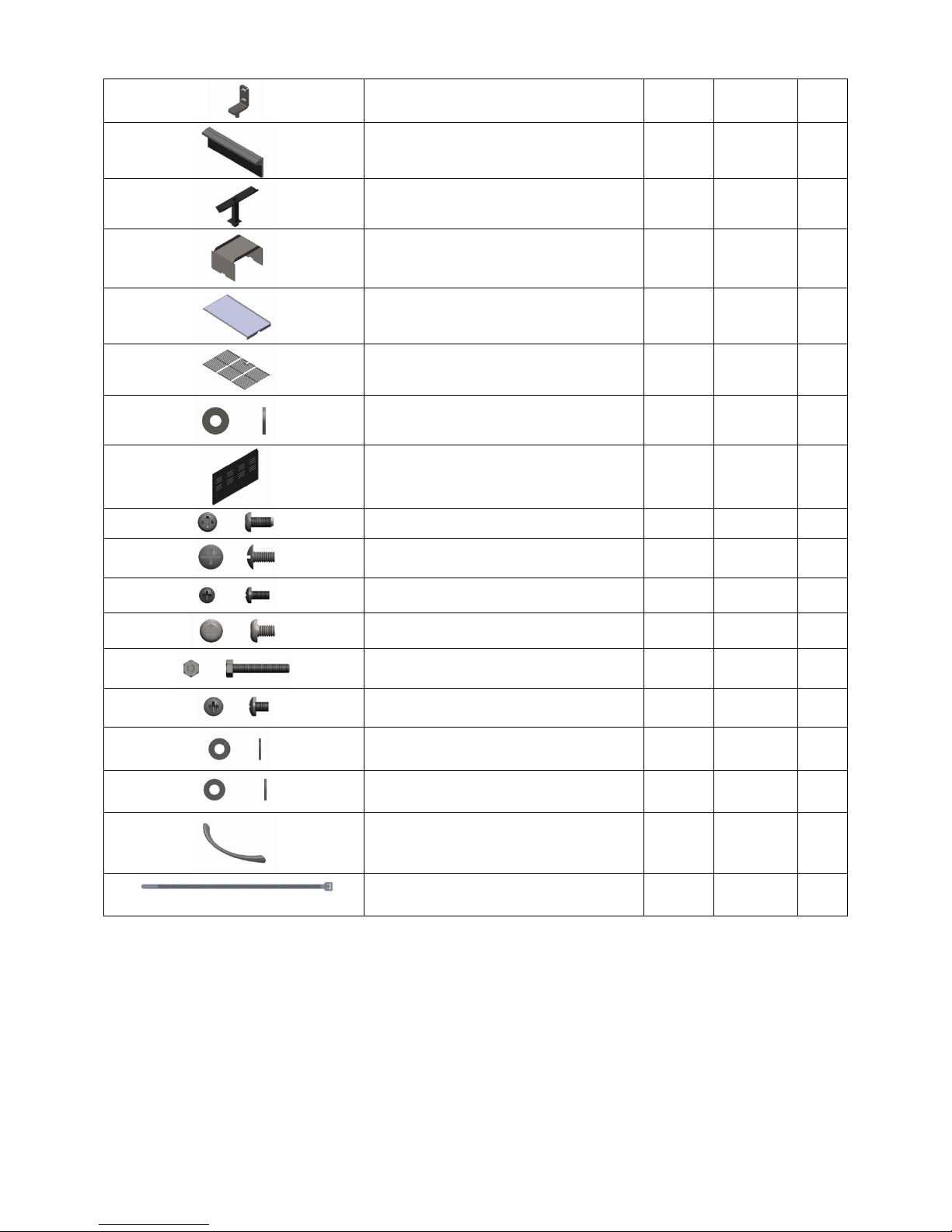
PARTS LIST
PART PREVIEW
DESCRIPTION
QTY
PART#
ID#
1/4-20 SHOULDER BOLT LONG
4
HDW154
A
WASHER 1/2OD X 1/4 ID FLAT ZINC
38
HDW072
B
TOP SECTION
1
C
1/4-20 x .625 PHILLIPS PAN HEAD
16
HDW066
D
1/4 Lock Washer Zinc
16
HDW113
E
1/4-20 x .500 Truss Head Screw Zinc
16
HDW095
F
8-32 x .500 PPHD Zinc
4
HDW245
G
Door Handle Gasket
2
INS147
H
Base Pan Assembly
1
SUB264
I
Right Panel Assembly
1
Sub267
J
Left Panel Assembly
1
SUB265
K
Swivel Caster
2
HDW051
L
Fixed Caster
2
HDW052
M
1
SUB268
N
1/4-20 SHOULDER BOLT SHORT
2
HDW155
O
Left Shelf Assembly
1
SUB267
P
Right Shelf Assembly
1
SUB278
Q
Handle
3
HDW227
R
Door Right
1
SUB274
S
Zinc
Hopper Burner Assembly
Door Left
2
1
SUB279
Page 3
Upper Hinge Assembly
2
SUB309
T
Front Panel Assembly
1
SUB260
BCA253
u
Grease Drain Assembly
1
SUB254
V
Heat Baffle
1
BCA289
W
Drip Pan
1
BCA288
X
Porcelain Grills
2
HDW093
Y
Washer 3/4 OD X 5/16 ID Zinc
8
HDW250
Z
Lower Back Panel Assembly
1
SUB266
AA
#8 X .375 Phillips Pan Head Zinc
8
HDW244
BB
1/4-20 X .500 Truss Head SST
4
HDW092
CC
8-32 X .375 PPHD SST
4
HDW097
DD
1/4-20 X .375 Phillips Pan Head Zinc
6
HDW251
EE
1/4-20 X 1.5 HEX HEAD BOLT
4
HDW156
FF
8-32 X .187 PPHD SST
2
HDW053
GG
#8 Lock Washer
2
HDW074
HH
#8 Flat Washer
2
HDW032
II
Hopper Lid Handle
1
FAB055
JJ
Wire tie
1
HDW128
KK
1
HDW094
Before assembly begins verify that you have all the correct parts from the above list of parts. The
hardware kit shown on page 3 includes all the screws, nuts, bolts, and gaskets required for assembly.
The back of the package identifies the ID# of the hardware as used in the instructions.
Tools needed for the assembly of the BBQ are:
A Phillips head screw driver, Flat head screw driver, and a 7/16 socket or nut driver or wrench.
Two people will be required to assemble the BBQ.
3
Page 4

HARDWARE KIT BACK
HARDWARE KIT FRONT
4
Page 5

1. Install fixed casters (M) onto the base stiffener
located to the right of the base pan assembly (I).
Secure using 4 each Phillips head bolt (D), lock
washer (E) and washer (B) per caster. Install
swivel casters (L) onto base stiffener located to
the left of the base pan assembly. Secure using 4
each Phillips head bolts (D), lock washer (E), and
washer(B) per caster. Install magnets by pushing
into rectangular cutouts provided.
2. Insert left panel assembly (K) onto base pan
assembly flush to the front and flush to the side.
Insert the screws (F) and washers (B) into holes
provided and secure loosely.
3. Insert right panel assembly (J) onto base pan
assembly flush to the front and flush to the side.
Insert the screws (F) and washers (B) into holes
provided and secure loosely.
5
Page 6

4. Insert lower back panel assembly (AA) onto base
pan assembly flush to the bottom and flush to
the back. Insert the 3 screws (F) and washers (B)
into the bottom holes and secure loosely. Insert
the 6 screws (B) and washers (F) into the holes
located on the inside of the back panel flange
and secure loosely.
5. Insert top section (C) of BBQ400 onto the base
section completed through steps 1-4. Insert 2
each shoulder bolts long (A) into holes provided
on right side and secure to base cabinet. Insert 2
each shoulder bolts long (A) into holes provided
on left side and secure to the base cabinet.
6. Insert 2 each shoulder bolts short (o) into holes
provided at the bottom of the back panel. Secure
to the base cabinet. At this time secure all screws
from section 4 on the inside securely.
6
Page 7

7. Before hopper installation ensure that the
connector for the temperature probe is inserted
into hole located on the right side of the hopper
mounting face. Insert hopper burner assembly
(N) onto BBQ on left side flush to the upper side
panel. From inside of firebox insert 4 each bolt
(FF) and washers (Z) into holes provided and
secure to hopper assembly. Secure hopper to
support using screw (F) and washer (B) through
support and into the end of the hopper
assembly. Plug in the temperature probe to the
mating connector from the digital temperature
controller. Wire tie (KK) the wires to the digital
probe out of the way as to not interfere with any
of the fans in the hopper area.
8. Install hopper lid handle (JJ) onto left shelf
assembly using holes for alignment. Insert lock
washer (HH) and washer (II) onto screw (GG) and
insert from inside the hopper lid into the handle
and secure. Do not over tighten. Repeat process
on other side.
9. The top front and back screws have been
installed on the grill (CC) they may need to be
loosened to allow insertion into the keyhole
cutout in the shelf. Install left shelf assembly (P)
onto the BBQ left side by inserting over the
hopper top and onto the screws with the keyhole
slot to hold in place. Secure using 2 screws (CC)
and 2 washers (Z) from the underneath side of
the shelf in 2 places. Flush the shelf front to back
and tighten all 4 screws.
7
Page 8

10. Insert 3 each screws (BB) into holes provided on
the inside of the shelf flange. Secure into the
hopper top flange to secure hopper to the shelf.
Loosen the screws for the shelf to adjust for
alignment if needed.
11. The top front and back screws have been
installed on the grill (CC) they may need to be
loosened to allow insertion into the keyhole
cutout in the shelf. Insert right shelf assembly (Q)
onto the screws using the keyhole slot to hold in
place. Install 2 each screws (CC) and washers (Z)
from the underneath side of the shelf. Center
shelf so it is flush front and back and secure to
cabinet side.
12. Insert handle (R) onto door (S) aligning with
holes provided. Insert washer (B), onto screw
(EE) and insert into the back panel of the door
into the door handle and secure. Repeat the
process in the top hole of the handle. Repeat
process on the other door.
8
Page 9

13. Insert upper door hinge (T) into hole provided on
door left. Insert the door onto the lower pin
located on the base pan. Insert screw (G) into
hinge bracket and secure to the cabinet. Repeat
the process on the right door. Adjust so the
doors are even and open without interference.
14. Insert gasket (H) onto handle (R) so it aligns.
Insert handle with gasket onto BBQ lid and align
with holes provided. Insert washer (B) onto
screw (EE) and install from the inside of the lid.
Secure into handle do not over tighten. Repeat
the process on the other hole for the handle.
15. Insert front trim part (U) onto BBQ flush side to
side and flush to the lower flange of the firebox.
Insert 2 screws (DD) into the right side of the
panel and secure to the trim base part. Repeat
the process for the screws on the left side.
9
Page 10

16. Insert grease drain assembly (V) into the inside of
the firebox and align with holes provided. Secure
using 5 screws (BB) to the right sidewall and base
of the firebox.
17. Insert heat baffle into the BBQ and insert into
the notches in the clips located at the base of the
firebox.
18. Install drip pan into BBQ with the small flange on
the bracket on the left side of the firebox. The
larger flange should go into the grease drain and
center front to back.
10
Page 11

19. Install Porcelain grill (Y) onto the BBQ inserting
the grills without the cutout onto the grill first.
You will need to tilt the grill up on the back side
and insert under flange and then down onto BBQ
surface. Keep the side grills flush to the outer
walls of the BBQ. Then insert the center grill onto
the BBQ the same way so the cutout is centered
over the probe guard. Adjust grills so that they
are touching together.
20. Insert grease bucket onto the inside of the lower
cabinet and hook onto the tab located on the
grease drain. Ensure that the bucket is centered
over the tube.
Read the instruction manual before using your Traeger BBQ400.
If you have any questions or problems contact Traeger Customer service. Contact information is located on the following
page.
11
Page 12

TRAEGER PELLET GRILLS, LLC.
9445 SW Ridder Road #310
Wilsonville, OR 97070
TRAEGER TECHNICAL SUPPORT
Available 7 Days a Week 5AM to 7PM
Pacific Time
TRAEGER PARTS DEPARTMENT
Available Weekdays 8AM to 4:30PM
Pacific Time
TRAEGER SALES/ORDER DESK
Available Weekdays 8AM to 4:30PM
Pacific Time
TOLL-FREE TELEPHONE: 1-800-872-3437
E-mail: service@traegergrills.com
Website: www.traegergrills.com
12
 Loading...