


 Loading...
ITM. / ART. 833852
OWNER’S MANUAL
BBQ07C.01
RESIDENTIAL PELLET GRILL FOR OUTDOOR USE ONLY!
“TASTE THE DIFFERENCE”
Please read this entire manual before assembly, installation of your Traeger Pellet Grill. Failure to follow these instructions could result in property damage, bodily injury or even death. Contact your local building or fire official about restrictions and installation inspection requirements in your area.
IMPORTANT, RETAIN FOR FUTURE REFERENCE: READ CAREFULLY.
If you are assembling this unit for someone else, provide this manual for the owner to read and save for future reference.
SAVE THESE INSTRUCTIONS

A MAJOR CAUSE OF FIRES IS FAILURE TO MAINTAIN REQUIRED CLEARANCES (AIR SPACES) TO COMBUSTIBLE MATERIALS. IT IS OF UTMOST IMPORTANCE THAT THIS PRODUCT BE INSTALLED ONLY IN ACCORDANCE WITH THESE INSTRUCTIONS.
DANGER! Hazardous voltage is present which can shock, burn or cause death. Disconnect the power cord before servicing the Grill unless otherwise noted in the Owner’s Manual.
DANGER! Never use or store flammable liquids near the Grill.
DANGER! Never use gasoline or lighter fluid to manually light your Grill. Use ONLY Alcohol Gel for this procedure AND according to the instructions in the Owner’s Manual.
WARNING! When operating this Grill, maintain a MINIMUM distance of 12” from the Grill to combustibles. WARNING! When operating this Grill under overhead combustibles a MINIMUM of 40 inches is required.
WARNING! Assemble and operate this Grill ONLY per the instructions in this Owner’s Manual. WARNING! This Grill is intended for OUTDOOR USE ONLY.
WARNING! Never use heating fuel pellets in the Grill, due to potential hazardous contaminants and additives that may be present.
WARNING! Use ONLY TRAEGER BRAND BBQ WOOD PELLETS, which are specifically made to work in our Grills. Traeger wood pellets are rated for 8500 BTU per LBS with an ash content of 2%. CAUTION! Always store wood pellets in a dry location, away from heat-producing appliances and other fuel containers.
CAUTION! Keep the Grill clean – See the cleaning Instructions in this Owner’s Manual. CAUTION! Do not use accessories not specified for use with this Grill.
1
INTRODUCTION
Congratulations on your purchase of this Traeger Wood Pellet Grill, Model BBQ07C.01.
With proper set-up, operation and maintenance, the Grill will provide you with delicious food and years of cooking enjoyment.
NOTE: NUMBERS FOLLOWING PART NAMES REFER TO THE COMPONENT DIAGRAM FOUND ON THE NEXT PAGE OF THIS MANUAL.
When you un-box the Grill, remove all parts from the box and inside the Grill. Remove any remaining packaging material from inside the Grill as well. Make sure you have, and can identify all of the following parts:
Qty |
Item Description |
Component Diagram Reference Number |
|
(1) |
Grill Frame Assembly------------------------------------------ |
|
1 |
(1) |
Hopper / Burner Assembly------------------------------------ |
|
3 |
(1) |
Lower Cabinet Assembly (see Exploded view)--------- |
4 |
|
(1) |
Heat Baffle-------------------------------------------------------- |
|
5 |
(1) |
Grease Drain Pan---------------------------------------------- |
|
6 |
(1) |
Warming Shelf---------------------------------------------------- |
|
7 |
(1) |
Porcelain Grill---------------------------------------------------- |
|
8 |
(1) |
Chrome Door Handle ------------------------------------------ |
|
19 |
(1) |
Chimney Cap Assembly --------------------------------------- |
|
22 |
(1) |
Flue Pipe --------------------------------------------------------- |
|
23 |
(1) |
Grease Bucket -------------------------------------------------- |
|
24 |
(1) |
Hardware Kit------------------------------------------------------ |
|
NA |
You will need to complete the assembly which includes:
1)Assemble lower Cabinet (4) and mount cabinet to grill frame (1).
2)Attaching the Chrome Door Handle (19) to the Door (20).
3)Attaching the Flue Pipe (23) to the Grill Frame Assembly (1).
4)Mounting the Chimney Cap Assembly (22).
5)Positioning the Heat Baffle (5) over the Hopper assembly (3).
6)Positioning the Grease Drain Pan (6) over the Heat Baffle (5).
7)Positioning the Porcelain Grill (8) and Warming Shelf (7).
8)Hanging the Grease Bucket (24).
TOOLS SUPPLIED FOR ASSEMBLY
(2) Open end wrenches.
(1) Hex key (Allen Wrench).
Tools you will need that are not supplied: 5/8 open end wrench.
Record your date of purchase here:_____________________________________________
Record your serial number here:________________________________________________
2

BBQ07C.01 COMPONENT LIST
HOPPER ASSEMBLY EXPLODED VIEW
3
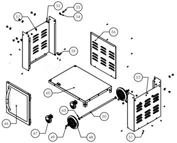
LOWER CABINET EXPLODED VIEW
BBQ07C.01 PARTS LIST
Item |
Qty |
Description |
P/N |
Item |
Qty |
Description |
P/N |
1 |
1 |
Grill Frame Assembly |
SUB743 |
32 |
1 |
Nut 6-32 Nylock Zinc |
HDW111 |
2 |
1 |
Heat Shield Assembly |
SUB750 |
33 |
1 |
Screw 6-32 x .75 Socket Hd |
HDW116 |
3 |
1 |
Hopper Burner Assembly |
SUB745 |
34 |
1 |
Auger Tube Bushing |
BRN109 |
4 |
1 |
Lower Cabinet Assembly |
SUB747 |
35 |
1 |
Auger Drive Motor ETL |
BRN250 |
5 |
1 |
Heat Baffle |
BCA726 |
36 |
1 |
Hopper Lid Assembly |
SUB730 |
6 |
1 |
Drip Pan |
BCA070 |
37 |
1 |
Hopper Guard |
BCA707 |
7 |
1 |
Warming Shelf |
HDW299 |
38 |
1 |
Hopper Assembly CC |
SUB279 |
8 |
1 |
Porcelain Grill |
HDW195 |
39 |
1 |
Hopper Bottom Cover |
BCA297 |
9 |
4 |
Bolt 1/4-20 x .75 Hex Zinc |
HDW137 |
40 |
1 |
DIGITAL CONTROL W/SDC |
BAC283 |
10 |
6 |
Washer .250 Flat |
HDW130 |
41 |
10 |
Screw 6-32 x .500 S-Tap SST |
HDW285 |
11 |
2 |
Bolt 1/4-20 x .500 Hex SST |
HDW287 |
42 |
1 |
Power Cord 8’ Nema 120v |
ELE203 |
12 |
4 |
Washer .250 Flat SST |
HDW292 |
43 |
1 |
Strain Relief |
ELE210 |
13 |
2 |
Nut 1/4-20 Hex SST |
HDW289 |
44 |
1 |
Screw 8-32 x .375 S-tap |
HDW114 |
14 |
4 |
Screw 8-32 x .50 PPHD SST |
HDW286 |
45 |
1 |
Draft Inducer Fan Assy ETL |
FAN250 |
15 |
1 |
Right Door Pivot Assembly |
HDW085 |
46 |
1 |
Cabinet Door Assembly |
SUB751 |
16 |
1 |
Left Door Pivot Assembly |
HDW086 |
47 |
2 |
3” Caster W/O Brake Black |
HDW295 |
17 |
2 |
Bolt 1/4-20 x .310 Hex Zinc |
HDW088 |
48 |
2 |
Wheel 6” Black |
HDW294 |
18 |
1 |
7” RTD Sensor |
BAC194 |
49 |
2 |
Acorn Nut .375-16 SST |
HDW293 |
19 |
1 |
12” Chrome Handle |
HDW227 |
50 |
1 |
Wheel Axle |
FAB119 |
20 |
1 |
Door Assembly |
SUB744 |
51* |
18 |
Screw 8-32 x PPHD SST |
HDW282 |
21 |
1 |
Flue Pipe Gasket |
INS145 |
52 |
1 |
Right Panel Assembly |
SUB740 |
22 |
1 |
Chimney Cap Assembly |
SUB732 |
53 |
14 |
Bolt 5/16-18 x Socket SST |
HDW277 |
23 |
1 |
Flue Pipe Assembly |
FAB309 |
54 |
14 |
Washer .312 Flat SST Black |
HDW278 |
24 |
1 |
Grease Bucket |
HDW152 |
55 |
14 |
Nut 5/16-18 Hex SST Black |
HDW279 |
25 |
1 |
Burner Box Assembly |
SUB002 |
56 |
1 |
Body Back Panel |
BCA735 |
26 |
1 |
Fire Pot Assembly 7 Hole CC |
SUB725 |
57 |
1 |
Left Panel Assembly |
SUB741 |
27 |
1 |
Burner Gasket |
INS144 |
59 |
2 |
Door Catch Magnet |
HDW297 |
28 |
1 |
Hot Rod (Ignitor) |
BAC199 |
60 |
1 |
Bottom Pan Assembly |
SUB748 |
29 |
8 |
Screw #8 x .5 Hex S-Tap |
HDW119 |
63 |
4 |
Washer Nylon 9/16 ID x 1.0 OD |
HDW312 |
30 |
1 |
3/8 x 3/16 Thick Gasket |
BRN900 |
|
|
|
|
31 |
1 |
Auger Assembly 07E |
SUB005 |
|
|
|
|
51*= There is an extra screw in the packaging only 17 are needed for the assembly.
4
SECTION ONE: ASSEMBLY INSTRUCTIONS
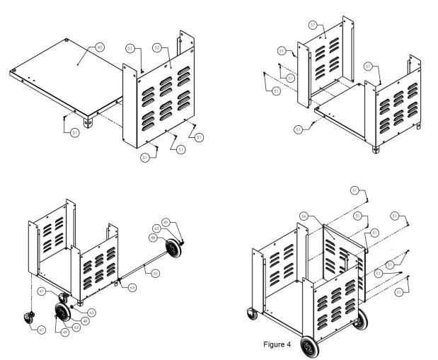
LOWER CABINET ASSEMBLY:
1)Insert the right panel assembly (52) onto the bottom pan assembly (60) flush to the sides and bottom. Secure using 5 8-32 screws (51). See Figure 1.
2)Insert left panel assembly (57) onto bottom pan assembly (60) flush to the sides and flush to the bottom. Secure using 5 8-32 screws (51). See Figure 2.
3)Install casters into tubes located on the bottom of the assembly. Insert the axle rod into holes on bottom pan assembly (60) then insert 2 nylon washers (63) one on both ends of the axle (50). Insert 2 wheels (48) onto axle. Secure using 2 nylon washers (63) and 2 5/6-18 acorn nuts (49). A 5/8” wrench (not included) will be needed to secure the nuts. Do not over tighten acorn nuts (49). See
Figure 3.
4)Remove the 2 lower screws on the back that hold the sides to the base pan. These will be reinserted after the next step. Insert cabinet back onto assembly with the flange facing up and align with holes in the sides. Secure using 7 screws
(including 2 of the previous lower screws) (51). See Figure 4.
Figure 1 |
Figure 2 |
Figure 3
5
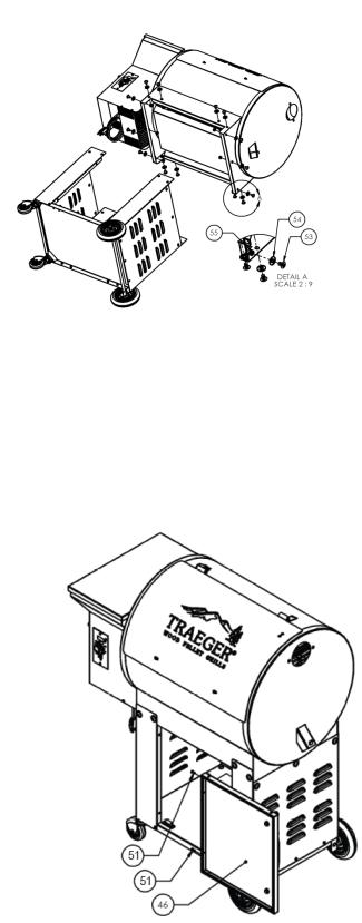
LOWER CABINET TO BODY ASSEMBLY:
Lay the grill body (1) onto its back. Insert the lower cabinet onto the grill frame body
(1) until the holes for the fasteners align. Then insert the 5/16-18 bolt (53) onto the washer (54) and insert into the right front of the lower cabinet. Then from the inside of the cabinet insert 5/16-18 nut (55) onto the bolt and hand tighten. Repeat this process until all 8 sets of fasteners are installed. Then stand up the grill assembly.
This will require 2 people to do this step. After the grill is upright then tighten the fasteners with the wrench and Hex Key (Allen Wrench) driver provided.
After you complete this step please remove the Styrofoam supports for the heat deflector. Do not use the grill with the Styrofoam in place.
LOWER CABINET DOOR ASSEMBLY:
1.To install door first ensure that the hinges of the door are open. Then place the door onto the frame of the cabinet so the hole in the hinge aligns with the hole in the cabinet. Then insert 8-32 screw (51) and thread into cabinet hand tight. Repeat the process on the lower hinge.
2.Then you will need to tighten the screws for the doors and adjust the doors and magnets until the door closes securely.
6
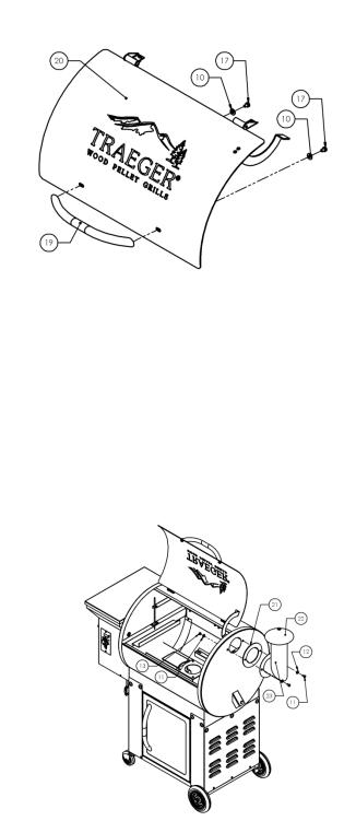
ATTACHING THE CHROME DOOR HANDLE:
1)Insert the bolt (17), flat washer (18) into the slot in the door and thread into the handle (19). Repeat the process on the other side.
2)Do not over tighten the bolts to the handle
ATTACHING THE FLUE PIPE AND CHIMNEY CAP ASSEMBLY:
1)Align the holes in the Flue Pipe (23) with the holes in the Flue Pipe Gasket (21), which fits between the right end of the Grill and the Flue Pipe (23). From the
Hardware Kit, place SST Flat Washers (12) on two of the 1/2” long Hex Head Bolts (11) and insert the Bolts through the holes in the Flue Pipe (23) and the Flue Pipe Gasket (21).Align the Bolts with the corresponding holes in the Grill.
Place a SST Flat Washer (12) on each Bolt inside the Grill and secure with SST
Hex Nuts (13) using the Wrench supplied.
2)Screw the Chimney Cap Assembly (22) into the Bracket in the top of the Flue Pipe. Hand-tighten the cap to the desired height.
NOTE: If at this point you are ready to start your Grill, refer to the INITIAL FIRING INSTRUCTIONS: in Section Two of this manual or on a separate sheet in the Pellet Hopper before proceeding with further assembly.
7
Loading...