


Bbq075.04

OWNER’S MANUAL
BBQ075.04
RESIDENTIAL PELLET GRILL
FOR OUTDOOR USE ONLY!
“TASTE THE DIFFERENCE”
Please read this entire manual before assembly, installation of your Traeger Pellet Grill.
Failure to follow these instructions could result in property damage, bodily injury or even
death. Contact your local building or fire official about restrictions and installation
inspection requirements in your area.
SAVE THESE INSTRUCTIONS
A MAJOR CAUSE OF FIRES IS FAILURE TO
MAINTAIN REQUIRED CLEARENCES (AIR
SPACES) TO COMBUSTIBLES MATERIALS. IT IS
OF UTMOST IMPORTANCE THAT THIS PRODUCT
BE INSTALLED ONLY IN ACCORDANCE WITH
THESE INSTRUCTIONS.
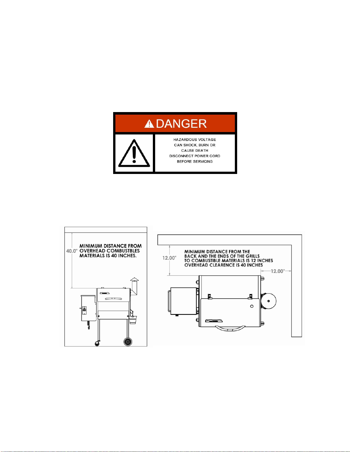
DANGER! Hazardous voltage is present which can shock, burn or cause death. Disc onnec t the power
cord before servicing the Grill unless otherwise noted in the Owner’s Manual.
DANGER! Never use or store flammable liquids near the Grill.
DANGER! Never use gasoline or lighter fluid to manually light your Grill. Use ONLY Alcohol Gel for this
procedure AND according to the instructions in the Owner’s Manual.
WARNING! When operating this Grill, maintain a MINIMUM distance of 12” from the Grill to combustibles.
WARNING! When operating this Grill under overhead combustibles a MINIMUM of 40 inches is required.
WARNING! Assemble and operate this Grill ONLY per the instructions in this Owner’s Manual.
WARNING! This Grill is intended for OUTDOOR USE ONLY.
WARNING! Never use heating fuel pellets in the Grill, due to potential hazardous contaminants and
additives that may be present.
WARNING! Use ONLY TRAEGER BRAND BBQ WOOD PELLETS, which are specifically made to work
in our Grills. Traeger wood pellets are rated for 8500 BTU per LBS with an ash content of 2%.
CAUTION! Always store wood pellets in a dry location, away from heat-producing appliances and other
fuel containers.
CAUTION! Keep the Grill clean – See the cleaning Instructions in this Owner’s Manual.
CAUTION! Do not use accessories not specified for use with this Grill.

INTRODUCTION
Congratulations on your purchase of this Traeger Wood Pellet Grill, Model BBQ075.04.
With proper set-up, operation and maintenance, the Grill will provide you with delicious
food and years of cooking enjoyment.
NOTE: NUMBERS FOLLOWING PART NAMES REFER TO THE COMPONENT
DIAGRAM FOUND NEAR THE END OF THIS MANUAL.
When you un-box the Grill, remove all parts from the box and inside the Grill. Remove any
remaining packaging material from inside the Grill as well. Make sure you have, and can
identify all of the following parts:
Qty Item Description Component Diagram Reference Number
(1) Grill Frame Assembly------------------------------------------ 2
(1) Hopper / Burner Assembly------------------------------------ 20
(2) Caster Leg Assemblies---------------------------------------- 99
(2) Wheel Le g Assemblies---------------------------------------- 104
(1) Porcelain Grill---------------------------------------------------- 147
(1) Grease Drain Pan----------------------------------------------- 141
(1) Heat Baffle-------------------------------------------------------- 140
(1) Flue Pipe---------------------------------------------------------- 113
(1) Chimney Cap Assembly--------------------------------------- 119
(1) Chrome Door Handle------------------------------------------- 143
(1) Grease Bucket---------------------------------------------------- 112
(1) Hardware Kit------------------------------------------------------ NA
You will need to complete the assembly which includes:
1) Mounting the Caster Leg Assemblies (99) and the Wheel Leg Assemblies (104) to the
Grill.
2) Attaching the Chrome Door Handle (143) to the Door (80).
3) Attaching the Flue Pipe (113) to the Gr ill Frame Assembly (2).
4) Mounting the Chimney Cap Assembly (119).
5) Positioning the Heat Baffle (140) over the Hopper assembly (20).
6) Positioning the Grease Drain Pan (141) over the Heat Baffle (140).
7) Positioning the Porcelain Grill (147) on the Grill Supports.
8) Hanging the Grease Bucket (112).
TOOLS ARE SUPPLIED FOR ASSEMBLY
(2) Open end wrenches (I)
(1) Hex key (Allen Wrench) (H)
Follow these step-by-step instructions and you’ll be cooking in no time!
Record your date of purchase here:_____________________________________________
Record your serial number here:_____________________________________________
SECTION ONE: ASSEMBLY INSTRUCTIONS
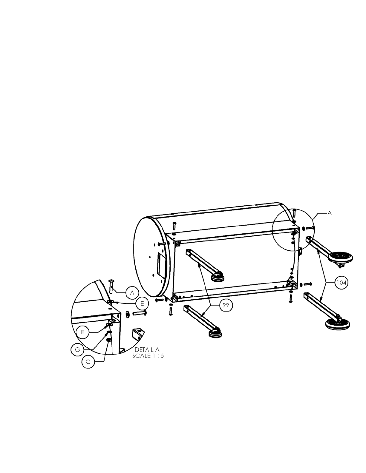
MOUNTING THE LEGS:
1) Carefully lay the Grill on its back on a non-abrasive surface.
2) Use the Black Bolts (A), Washers (E, G ) and Nuts (C) supplied in the hardware
kit to install the Caster Leg Assemblies (99) on the left end of the Grill and the
Wheel Leg Assemblies (104) on the right end of the Grill, as shown in the upper
diagram below. The Nuts (C) on the Wheel Leg Assemblies (104) should go
toward the center of the Grill. You may need to rotate the Grill toward the back to
accommodate the Leg Assemblies (99 & 104) on the rear of the Grill. Leave the
Nuts loose during this step.
3) Set the Grill upright to level and then tighten all Nuts.
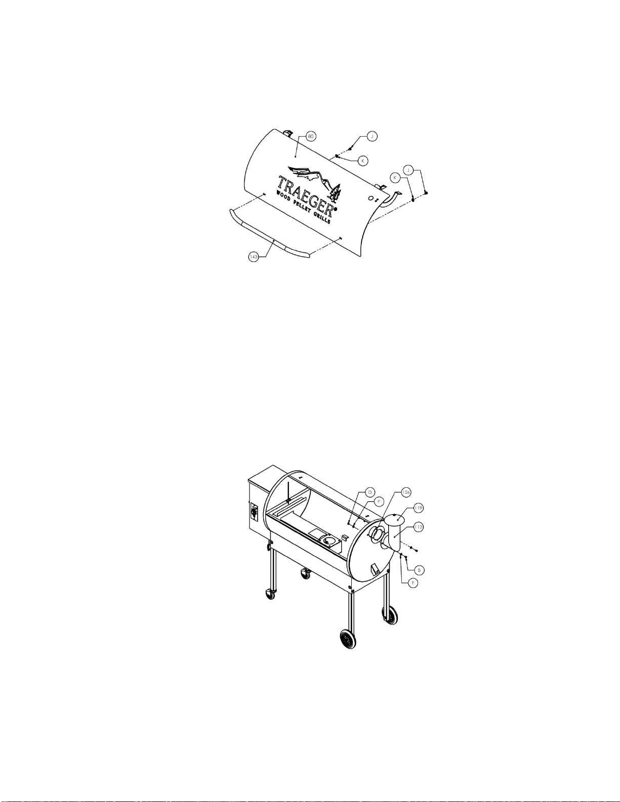
ATTACHING THE CHROME DOOR HANDLE:
1) Insert the bol t (J ), fla t washer (K) into the slot in the door (80) and thread into the
handle (143). Repeat the process on the other side.
2) Do not over tighten the bolts to the handle
ATTACHING THE FLUE PIPE AND CHIMN EY CAP ASSEMBLY:
1) Align the holes in the Flue Pipe (113) with the holes in the Flue Pipe Gasket
(126), which fits between the right end o f the Gri l l and the Flue Pipe (113). From
the Hardware Kit, place Zinc Flat Washers (F) on two of the 1/2” long Hex Head
Bolts (B) and insert the Bolts through the holes in the Flue Pipe (113) and the
Flue Pipe Gasket (126).Align the Bolts with the corresponding holes in the Grill.
Place a Zinc Flat Washer (F) on each Bolt inside the Grill and secure with Zinc
Hex Nuts (D) using the Wrench supplied.
2) Screw the Chimney Cap Assembly (119) into the Bracket in the top of the Flue
Pipe. Hand tighten the cap to the desired height.
NOTE: If at this point you are ready to start your Grill, refer to the INITIAL FIRING
INSTRUCTIONS in Section Two of this manual or on a separate sheet in the Pellet
Hopper before proceeding with further assembly.

WARNING!
Many parts of the Grill will become very hot during operation. Care must be taken
to avoid burns, both during operation and afterwards, while the Grill is still hot. It
should never be left unattended when young children are present. Never move
the Grill when it is operating. Let it thoroughly cool before moving or attempting
to transport.
POSITIONING THE HEAT BAFFLE:
1) Position The Heat Ba ffl e (140) directly over the Firepot on the locating brackets
found on the inside walls of the Grill. The notched legs of the Heat Baffle (140)
should be facing downward to fit onto the locating brackets.
POSITIONING THE GREASE DRAIN PAN:
1) Position the Grease Drain Pan (141) so that the Short Lip end hooks over the
Grease Drain Pan Support on the left side of the Grill. The Long Lip end should
rest in the V-Shaped Grease Drain located inside the Grill on the right.
RECOMMENDATION for ease of clean-up: Line the Grease Drain Pan (141) with
Heavy duty aluminum foil. Be sure the edges and ends of the foil are tight against
the bottom of the Grease Drain Pan (141).
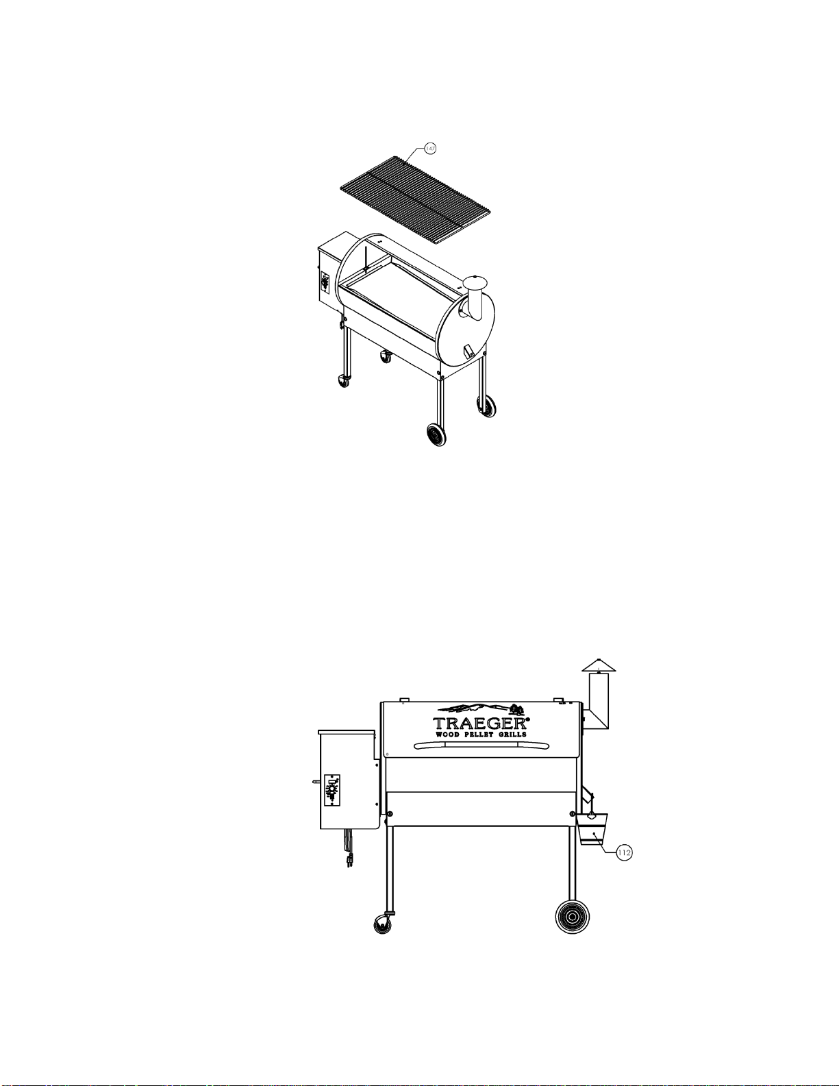
POSITIONING THE PORCELAIN GRILL:
1) Position the Porcelain Grill (147) on the Grill Supports that run the length of the
cooking area.
HANGING THE GREASE BUCKET:
1) Locate the Grease Drain Tube, extending from the Grill below the Smoke Stack
on the right end. Hang the Grease Bucket (112) on the Bucket Hook.
 Loading...