

Page 1

User Guide
JetStream 52-Port Gigabit Stackable L3 Managed Switch
T3700G-52TQ
REV1.0.0
1910011776
Page 2

COPYRIGHT & TRADEMARKS
Specifications are subject to change without notice. is a registered trademark of
TP-Link Technologies Co., Ltd. Other brands and product names are trademarks or registered
trademarks of their respective holders.
No part of the specifications may be reproduced in any form or by any means or used to make
any derivative such as translation, transformation, or adaptation without permission from
TP-Link Technologies Co., Ltd. Copyright © 2017 TP-Link Technologies Co., Ltd. All rights
reserved.
http://www.tp-link.com
FCC STATEMENT
This equipment has been tested and found to comply with the limits for a Class A digital device,
pursuant to part 15 of the FCC Rules. These limits are designed to provide reasonable
protection against harmful interference when the equipment is operated in a commercial
environment. This equipment generates, uses, and can radiate radio frequency energy and, if
not installed and used in accordance with the instruction manual, may cause harmful
interference to radio communications. Operation of this equipment in a residential area is likely
to cause harmful interference in which case the user will be required to correct the interference
at his own expense.
This device complies with part 15 of the FCC Rules. Operation is subject to the following two
conditions:
1) This device may not cause harmful interference.
2) This device must accept any interference received, including interference that may
cause undesired operation.
Any changes or modifications not expressly approved by the party responsible for compliance
could void the user’s authority to operate the equipment.
CE Mark Warning
This is a class A product. In a domestic environment, this product may cause radio interference,
in which case the user may be required to take adequate measures.
Industry Canada Statement
CAN ICES-3 (A)/NMB-3(A)
I
Page 3

Продукт сертифіковано згідно с правилами системи УкрСЕПРО на відповідність вимогам
нормативних документів та вимогам, що передбачені чинними законодавчими актами
України.
Safety Information
When product has power button, the power button is one of the way to shut off the
product; When there is no power button, the only way to completely shut off power is to
disconnect the product or the power adapter from the power source.
Don’t disassemble the product, or make repairs yourself. You run the risk of electric shock
and voiding the limited warranty. If you need service, please contact us.
Avoid water and wet locations.
安全諮詢及注意事項
●請使用原裝電源供應器或只能按照本產品注明的電源類型使用本產品。
●清潔本產品之前請先拔掉電源線。請勿使用液體、噴霧清潔劑或濕布進行清潔。
●注意防潮,請勿將水或其他液體潑灑到本產品上。
●插槽與開口供通風使用,以確保本產品的操作可靠並防止過熱,請勿堵塞或覆蓋開口。
●請勿將本產品置放於靠近熱源的地方。除非有正常的通風,否則不可放在密閉位置中。
●請不要私自打開機殼,不要嘗試自行維修本產品,請由授權的專業人士進行此項工作。
此為甲類資訊技術設備,于居住環境中使用時,可能會造成射頻擾動,在此種情況下,使用者會被
要求採取某些適當的對策。
この装置は、クラス A 情報技術装置です。この装置を家庭環境で使用すると電波妨害を引き起こ
すことがあります。この場合には使用者が適切な対策を講ずるよう要求されることがあります。
VCCI-A
II
Page 4

Symbol
Explanation
the choice to give his product to a competent recycling
organization or to the retailer when he buys a new electrical or
electronic equipment.
Explanation of the symbols on the product label
AC voltage
Indoor use only
RECYCLING
This product bears the selective sorting symbol for Waste electrical
and electronic equipment (WEEE). This means that this product must
be handled pursuant to European directive 2012/19/EU in order to be
recycled or dismantled to minimize its impact on the environment.
User has
III
Page 5

CONTENTS
Package Contents ........................................................................................................................... 1
Chapter 1 About This Guide ........................................................................................................... 2
1.1 Intended Readers .......................................................................................................... 2
1.2 Conventions .................................................................................................................. 2
1.3 Overview of This Guide.................................................................................................. 3
Chapter 2 Introduction ................................................................................................................... 8
2.1 Overview of the Switch .................................................................................................. 8
2.2 Appearance Description ............................................................................................... 8
2.2.1 Front Panel .......................................................................................................... 8
2.2.2 Rear Panel ......................................................................................................... 10
Chapter 3 Login to the Switch ..................................................................................................... 12
3.1 Login ............................................................................................................................ 12
3.2 Configuration ............................................................................................................... 12
Chapter 4 System ........................................................................................................................ 14
4.1 System Info .................................................................................................................. 14
4.1.1 System Summary ............................................................................................. 14
4.1.2 Device Description ........................................................................................... 16
4.1.3 System Time ..................................................................................................... 17
4.1.4 Daylight Saving Time ........................................................................................ 18
4.1.5 System IPv6 ...................................................................................................... 19
4.1.6 Management Port IPv4 ..................................................................................... 22
4.1.7 Management Port IPv6 ..................................................................................... 23
4.2 User Management ....................................................................................................... 24
4.2.1 User Table ......................................................................................................... 25
4.2.2 User Config ....................................................................................................... 25
4.3 System Tools ............................................................................................................... 26
4.3.1 Boot Config ....................................................................................................... 26
4.3.2 Config Restore .................................................................................................. 27
4.3.3 Config Backup .................................................................................................. 28
4.3.4 Firmware Upgrade ............................................................................................ 29
4.3.5 System Reboot ................................................................................................. 29
4.3.6 System Reset .................................................................................................... 30
4.4 Access Security ........................................................................................................... 30
IV
Page 6

4.4.1 Access Control ................................................................................................. 30
4.4.2 HTTP Config ...................................................................................................... 31
4.4.3 HTTPS Config ................................................................................................... 32
4.4.4 SSH Config ........................................................................................................ 35
4.4.5 Telnet Config .................................................................................................... 39
4.5 SDM Template ............................................................................................................. 39
4.5.1 SDM Template Config ...................................................................................... 39
Chapter 5 Stack ............................................................................................................................ 41
5.1 Stack Management ..................................................................................................... 47
5.1.1 Stack Info .......................................................................................................... 48
5.1.2 Stack Config ..................................................................................................... 49
5.1.3 Auto Copy Software ......................................................................................... 51
5.2 Application Example for Stack .................................................................................... 52
Chapter 6 Switching ..................................................................................................................... 53
6.1 Port ............................................................................................................................... 53
6.1.1 Port Config ........................................................................................................ 53
6.1.2 Port Mirror ......................................................................................................... 54
6.1.3 Port Security ..................................................................................................... 57
6.1.4 Protected Ports ................................................................................................ 58
6.1.5 Loopback Detection ......................................................................................... 59
6.1.6 Default Settings ................................................................................................ 62
6.2 LAG............................................................................................................................... 62
6.2.1 LAG Table .......................................................................................................... 63
6.2.2 Static LAG ......................................................................................................... 65
6.2.3 LACP Config ..................................................................................................... 66
6.2.4 Default Settings ................................................................................................ 67
6.3 Traffic Monitor ............................................................................................................. 68
6.3.1 Traffic Summary ............................................................................................... 68
6.3.2 Traffic Statistics ................................................................................................ 69
6.4 MAC Address ............................................................................................................... 71
6.4.1 Address Table ................................................................................................... 71
6.4.2 Static Address .................................................................................................. 73
6.4.3 Dynamic Address ............................................................................................. 74
6.4.4 Filtering Address .............................................................................................. 76
V
Page 7

Chapter 7 VLAN ............................................................................................................................ 78
7.1 802.1Q VLAN ............................................................................................................... 79
7.1.1 VLAN Config ..................................................................................................... 81
7.1.2 Port Config ........................................................................................................ 82
7.2 Application Example for 802.1Q VLAN ....................................................................... 84
7.3 MAC VLAN ................................................................................................................... 86
7.4 Application Example for MAC VLAN ........................................................................... 87
7.5 Protocol VLAN ............................................................................................................. 88
7.5.1 Protocol Group Table ....................................................................................... 89
7.5.2 Protocol Group ................................................................................................. 90
7.5.3 Protocol Template ............................................................................................ 90
7.6 Application Example for Protocol VLAN ..................................................................... 91
7.7 VLAN VPN .................................................................................................................... 93
7.7.1 VLAN-VPN Config ............................................................................................. 94
7.7.2 Default Settings ................................................................................................ 95
7.8 GVRP ............................................................................................................................ 95
7.8.1 GVRP Config ..................................................................................................... 97
7.8.2 Default Settings ................................................................................................ 98
7.9 Private VLAN ................................................................................................................ 98
7.9.1 PVLAN Config ................................................................................................. 100
7.9.2 Port Config ...................................................................................................... 101
7.10 Application Example for Private VLAN...................................................................... 102
Chapter 8 Spanning Tree ........................................................................................................... 105
8.1 STP Config .................................................................................................................. 111
8.1.1 STP Config ...................................................................................................... 111
8.1.2 STP Summary ................................................................................................. 113
8.2 Port Config .................................................................................................................. 113
8.3 MSTP Instance ............................................................................................................ 11 6
8.3.1 Region Config ................................................................................................. 117
8.3.2 Instance Config............................................................................................... 117
8.3.3 Instance Port Config ....................................................................................... 118
8.4 STP Security .............................................................................................................. 121
8.4.1 Port Protect .................................................................................................... 121
8.5 Application Example for MSTP Function .................................................................. 124
VI
Page 8

Chapter 9 Multicast .................................................................................................................... 129
9.1 IGMP Snooping .......................................................................................................... 131
9.1.1 Snooping Config ............................................................................................. 133
9.1.2 Port Config ...................................................................................................... 134
9.1.3 VLAN Config ................................................................................................... 135
9.1.4 Querier Config ................................................................................................ 137
9.1.5 Profile Config .................................................................................................. 139
9.2 MLD Snooping ........................................................................................................... 141
9.2.1 Snooping Config ............................................................................................. 142
9.2.2 Port Config ...................................................................................................... 144
9.2.3 VLAN Config ................................................................................................... 145
9.2.4 Querier Config ................................................................................................ 146
9.2.5 Profile Config .................................................................................................. 148
9.3 MVR ............................................................................................................................ 150
9.3.1 MVR Config ..................................................................................................... 150
9.3.2 Interface Config .............................................................................................. 151
9.3.3 Member Config ............................................................................................... 153
9.3.4 Traffic .............................................................................................................. 154
9.4 Multicast Table .......................................................................................................... 155
9.4.1 Summary ......................................................................................................... 155
9.4.2 Static Config ................................................................................................... 156
9.4.3 IGMP Snooping ............................................................................................... 158
9.4.4 MLD Snooping ................................................................................................ 158
9.4.5 SSM Groups .................................................................................................... 159
9.4.6 SSM Entries .................................................................................................... 160
9.4.7 SSM Status ..................................................................................................... 161
Chapter 10 Routing ...................................................................................................................... 163
10.1 Interface ..................................................................................................................... 163
10.2 Routing Table ............................................................................................................. 166
10.3 Static Routing ............................................................................................................ 167
10.3.1 Static Routing ................................................................................................. 167
10.3.2 Application Example for Static Routing ......................................................... 168
10.4 DHCP Server .............................................................................................................. 169
10.4.1 DHCP Server ................................................................................................... 175
VII
Page 9

10.4.2 Pool Setting .................................................................................................... 177
10.4.3 DHCP Options Set .......................................................................................... 179
10.4.4 Binding Table .................................................................................................. 180
10.4.5 Packet Statistics ............................................................................................. 181
10.4.6 Application Example for DHCP Server and Relay .......................................... 182
10.5 DHCP Relay ................................................................................................................ 184
10.5.1 Global Config .................................................................................................. 186
10.5.2 DHCP Server ................................................................................................... 188
10.6 Proxy ARP .................................................................................................................. 189
10.6.1 Proxy ARP ....................................................................................................... 189
10.6.2 Local Proxy ARP ............................................................................................. 190
10.6.3 Application Example for Proxy ARP ............................................................... 191
10.7 ARP ............................................................................................................................. 191
10.7.1 ARP Table ........................................................................................................ 191
10.7.2 Static ARP ....................................................................................................... 192
10.8 RIP .............................................................................................................................. 193
10.8.1 Basic Config .................................................................................................... 197
10.8.2 Interface Config .............................................................................................. 199
10.8.3 Application Example for RIP ........................................................................... 200
10.9 OSPF .......................................................................................................................... 201
10.9.1 Process ........................................................................................................... 219
10.9.2 Basic ................................................................................................................ 220
10.9.3 Network ........................................................................................................... 222
10.9.4 Interface .......................................................................................................... 223
10.9.5 Area ................................................................................................................. 228
10.9.6 Area Aggregation ........................................................................................... 230
10.9.7 Virtual Link ...................................................................................................... 231
10.9.8 Route Redistribution ....................................................................................... 233
10.9.9 Neighbor Table ............................................................................................... 234
10.9.10 Link State Database ....................................................................................... 236
10.9.11 Application Example for OSPF ....................................................................... 237
10.10 VRRP .......................................................................................................................... 238
10.10.1 Basic Config .................................................................................................... 242
10.10.2 Advanced Config ............................................................................................ 245
VIII
Page 10

10.10.3 Virtual IP Config .............................................................................................. 246
10.10.4 Track Config ................................................................................................... 248
10.10.5 Virtual Router Statistics .................................................................................. 249
10.10.6 Application Example for VRRP ....................................................................... 251
Chapter 11 Multicast Routing ...................................................................................................... 253
11.1 Global Config ............................................................................................................. 254
11.1.1 Global Config .................................................................................................. 254
11.1.2 Mroute Table ................................................................................................... 255
11.2 IGMP ........................................................................................................................... 256
11.2.1 Global Config .................................................................................................. 260
11.2.2 Interface Config .............................................................................................. 261
11.2.3 Interface State ................................................................................................ 262
11.2.4 Multicast Group Table .................................................................................... 263
11.2.5 Application Example for IGMP ........................................................................ 264
11.3 PIM DM ....................................................................................................................... 266
11.3.1 PIM DM Interface ............................................................................................ 271
11.3.2 PIM DM Neighbor ............................................................................................ 271
11.3.3 Application Example for PIM DM .................................................................... 273
11.4 PIM SM ....................................................................................................................... 274
11.4.1 PIM SM Interface ............................................................................................ 280
11.4.2 PIM SM Neighbor ............................................................................................ 281
11.4.3 BSR .................................................................................................................. 281
11.4.4 RP .................................................................................................................... 283
11.4.5 RP Mapping ..................................................................................................... 285
11.4.6 RP Info ............................................................................................................. 285
11.4.7 PIM SSM .......................................................................................................... 286
11.4.8 Packet Statistics ............................................................................................. 287
11.4.9 Application Example for PIM SM .................................................................... 288
11.5 Static Mroute ............................................................................................................. 290
11.5.1 Static Mroute Config ...................................................................................... 291
11.5.2 Application Example for Static Mroute .......................................................... 292
Chapter 12 QoS ............................................................................................................................ 295
12.1 Class of Service ......................................................................................................... 298
12.1.1 Trust Mode ...................................................................................................... 298
IX
Page 11

12.1.2 Port Priority ..................................................................................................... 298
12.1.3 802.1P/CoS to Queue Mapping ..................................................................... 300
12.1.4 DSCP to Queue Mapping................................................................................ 301
12.1.5 Schedule Mode ............................................................................................... 303
12.2 DiffServ ...................................................................................................................... 304
12.2.1 Global .............................................................................................................. 304
12.2.2 Class Summary ............................................................................................... 306
12.2.3 Class Config .................................................................................................... 306
12.2.4 Policy Summary .............................................................................................. 309
12.2.5 Policy Config ................................................................................................... 310
12.2.6 Service Config ................................................................................................ 312
12.3 Bandwidth Control ..................................................................................................... 313
12.3.1 Rate Limit ........................................................................................................ 313
12.3.2 Storm Control ................................................................................................. 314
12.4 Voice VLAN ................................................................................................................ 315
12.4.1 Global Config .................................................................................................. 316
12.4.2 Port Config ...................................................................................................... 316
12.4.3 OUI Config ....................................................................................................... 317
12.5 Auto VoIP ................................................................................................................... 318
12.5.1 Auto VoIP Config ............................................................................................ 318
Chapter 13 ACL ............................................................................................................................ 321
13.1 Time-Range ............................................................................................................... 321
13.1.1 Time-Range Summary .................................................................................... 321
13.2 ACL Config ................................................................................................................. 323
13.2.1 ACL Summary ................................................................................................. 323
13.2.2 ACL Create...................................................................................................... 324
13.2.3 MAC ACL ......................................................................................................... 324
13.2.4 Standard-IP ACL ............................................................................................. 326
13.2.5 Extend-IP ACL ................................................................................................. 327
13.3 ACL Binding ............................................................................................................... 329
13.3.1 Binding Table .................................................................................................. 330
13.3.2 Port Binding .................................................................................................... 331
13.3.3 VLAN Binding .................................................................................................. 332
Chapter 14 Network Security ...................................................................................................... 334
X
Page 12

14.1 IP-MAC Binding .......................................................................................................... 334
14.1.1 Binding Table .................................................................................................. 334
14.1.2 Manual Binding................................................................................................ 335
14.2 DHCP Snooping ......................................................................................................... 336
14.2.1 Global Config .................................................................................................. 339
14.2.2 Port Config ...................................................................................................... 341
14.3 ARP Inspection .......................................................................................................... 342
14.3.1 ARP Detect ...................................................................................................... 345
14.3.2 ARP Defend ..................................................................................................... 346
14.3.3 ARP Statistics ................................................................................................. 347
14.4 IP Source Guard ......................................................................................................... 348
14.5 DoS Defend ............................................................................................................... 349
14.5.1 DoS Defend ..................................................................................................... 350
14.6 802.1X ........................................................................................................................ 351
14.6.1 Global Config .................................................................................................. 355
14.6.2 Port Config ...................................................................................................... 355
14.7 AAA ............................................................................................................................ 358
14.7.1 RADIUS Server Config .................................................................................... 359
14.7.2 TACACS+ Server Config ................................................................................ 359
14.7.3 Authentication Method List Config ................................................................ 360
14.7.4 Application Authentication List Config .......................................................... 362
14.7.5 802.1X Authentication Server Config ............................................................ 363
14.7.6 Default Settings .............................................................................................. 363
Chapter 15 SNMP ......................................................................................................................... 365
15.1 SNMP Config ............................................................................................................. 367
15.1.1 Global Config .................................................................................................. 367
15.1.2 SNMP View ...................................................................................................... 368
15.1.3 SNMP Group ................................................................................................... 369
15.1.4 SNMP User ...................................................................................................... 371
15.1.5 SNMP Community .......................................................................................... 372
15.2 Notification ................................................................................................................ 375
15.2.1 Notification Config .......................................................................................... 375
15.2.2 Traps Config ................................................................................................... 378
15.3 RMON ......................................................................................................................... 380
XI
Page 13

15.3.1 History ............................................................................................................. 381
15.3.2 Event ............................................................................................................... 382
15.3.3 Alarm ............................................................................................................... 383
Chapter 16 LLDP .......................................................................................................................... 385
16.1 Basic Config ............................................................................................................... 388
16.1.1 Global Config .................................................................................................. 388
16.1.2 Port Config ...................................................................................................... 389
16.2 Device Info ................................................................................................................. 391
16.2.1 Local Info ........................................................................................................ 391
16.2.2 Neighbor Info .................................................................................................. 392
16.3 Device Statistics ........................................................................................................ 393
16.4 LLDP-MED ................................................................................................................. 395
16.4.1 Global Config .................................................................................................. 395
16.4.2 Port Config ...................................................................................................... 396
16.4.3 Local Info ........................................................................................................ 398
16.4.4 Neighbor Info .................................................................................................. 399
Chapter 17 Maintenance.............................................................................................................. 401
17.1 System Monitor ......................................................................................................... 401
17.1.1 CPU Monitor .................................................................................................... 401
17.1.2 Memory Monitor ............................................................................................. 402
17.2 Log ............................................................................................................................. 402
17.2.1 Log Table ........................................................................................................ 403
17.2.2 Local Log ........................................................................................................ 404
17.2.3 Remote Log .................................................................................................... 405
17.2.4 Backup Log ..................................................................................................... 406
17.3 Device Diagnose........................................................................................................ 407
17.3.1 Cable Test ....................................................................................................... 407
17.4 Network Diagnose ..................................................................................................... 408
17.4.1 Ping ................................................................................................................. 408
17.4.2 Tracert............................................................................................................. 409
Appendix A: Glossary .................................................................................................................. 410
XII
Page 14

Package Contents
The following items should be found in your box:
One T3700G-52TQ switch
One Power Cord
One Console Cable
One USB Cable
One Power Supply Module Slot Cover
Two mounting brackets and other fittings
Installation Guide
Resource CD for T3700G-52TQ switch, including:
• This User Guide
• The Command Line Interface Guide
• SNMP Mibs
• 802.1X Client Software and its User Guide
• Other Helpful Information
Note:
Make sure that the package contains the above items. If any of the listed items are damaged or
missing, please contact your distributor.
1
Page 15

Symbol
Description
Note:
device.
Tips:
of your device.
Chapter 1 About This Guide
This User Guide contains information for setup and management of T3700G-52TQ switch.
Please read this guide carefully before operation.
1.1 Intended Readers
This Guide is intended for network managers familiar with IT concepts and network
terminologies.
1.2 Conventions
When using this guide, please notice that features of the switch may vary slightly depending on
the model and software version you have, and on your location, language, and Internet service
provider. All screenshots, images, parameters and descriptions documented in this guide are
used for demonstration only.
The information in this document is subject to change without notice. Every effort has been
made in the preparation of this document to ensure accuracy of the contents, but all
statements, information, and recommendations in this document do not constitute the
warranty of any kind, express or implied. Users must take full responsibility for their application
of any products.
In this Guide the following conventions are used:
The switch or T3700G-52TQ mentioned in this Guide stands for T3700G-52TQ JetStream
52-Port Gigabit Stackable L3 Managed Switch without any explanation.
Menu Name→Submenu Name→Tab page indicates the menu structure. System→System
Info→System Summary means the System Summary page under the System Info menu
option that is located under the System menu.
Bold font indicates a button, a toolbar icon, menu or menu item.
Symbols in this Guide:
Ignoring this type of note might result in a malfunction or damage to the
This format indicates important information that helps you make better use
More Info:
The latest software, management app and utility can be found at Download Center at
http://www.tp-link.com/support.
2
Page 16

Chapter
Introduction
Chapter 1 About This Guide
Introduces the guide structure and conventions.
ance of
T3700G-52TQ switch.
page.
This module is used to configure system properties of the
System Info: Configure the description, system time and
: Configure the user name and password
SDM Template: Manage the hardware TCAM resources.
the Auto Copy Software
function.
MAC Address: Configure the address table of the switch.
The Installation Guide (IG) can be found where you find this guide or inside the package of
the switch.
Specifications can be found on the product page at
A Technical Support Forum is provided for you to discuss our products at
http://forum.tp-link.com
Our Technical Support contact information can be found at the Contact Technical Support
page at
http://www.tp-link.com/support
.
.
http://www.tp-link.com.
1.3 Overview of This Guide
Chapter 2 Introduction Introduces the features, application and appear
Chapter 3 Login to the Switch Introduces how to log on to T3700G-52TQ Web management
Chapter 4 System
switch. Here mainly introduces:
network parameters of the switch.
User Management
for users to manage the switch with a certain access level.
System Tools: Manage the configuration file of the switch.
Access Security: Provide different security measures for the
user to enhance the configuration management security.
Chapter 5 Stack This module is used to configure the stack properties of the
switch. Here mainly introduces:
Stack Info: View the detailed information of the stack.
Stack Config: Configure the current stack.
Auto Copy Software: Configure
Chapter 6 Switching This module is used to configure basic functions of the switch.
Here mainly introduces:
Port: Configure the basic features for the port.
LAG: Configure Link Aggregation Group. LAG is to combine a
number of ports together to make a single high-bandwidth
data path.
Traffic Monitor: Monitor the traffic of each port
3
Page 17

Chapter
Introduction
Chapter 7 VLAN
This module is used to configure VLANs to control broadcast in
VLAN VPN: VLAN VPN allows the packets with VLAN tags of
private networks to be encapsulated with VLAN tags of
public networks at the network access terminal of the
allows the switch to automatically add or
remove the VLANs via the dynamic VLAN registration
information and propagate the local VLAN registration
Designed to save VLAN resources of uplink
separation and to save VLAN resources of uplink devices.
STP Config: Configure and view the global settings of
STP Security: Configure protection function to prevent
devices from any malicious attack against STP features.
of the
IGMP Snooping: Configure global parameters of IGMP
Snooping function, port properties, VLAN and multicast
MLD Snooping: Configure global parameters of MLD
Snooping function, port properties, VLAN and multicast
Configure the Multicast VLAN Registration (MVR)
Multicast Table: View different types of multicast table.
LANs. Here mainly introduces:
802.1Q VLAN: Configure port-based VLAN.
MAC VLAN: Configure MAC-based VLAN without changing
the 802.1Q VLAN configuration.
Protocol VLAN: Create VLANs in application layer to make
some special data transmitted in the specified VLAN.
Internet Service Provider.
GVRP: GVRP
information to other switches, without having to individually
configure each VLAN.
Private VLAN:
devices and decrease broadcast. Private VLAN mainly used
in campus or enterprise networks to achieve user layer-2-
Chapter 8 Spanning Tree This module is used to configure spanning tree function of the
switch. Here mainly introduces:
spanning tree function.
Port Config: Configure CIST parameters of ports.
MSTP Instance: Configure MSTP instances.
Chapter 9 Multicast This module is used to configure multicast function
switch. Here mainly introduces:
VLAN.
VLAN.
MVR:
feature.
4
Page 18

Chapter
Introduction
Configure and view different types of interfaces:
to assign IP
RIP is an interior gateway
protocol using UDP data packets to exchange routing
VRRP: Configure the Virtual Router Redundant Protocol.
multicast routing
Static Mroute: Configure the static multicast routing
features.
This module is used to configure QoS function to provide
priorities, port priority, 802.1P
transmission of voice traffic
Chapter 10 Routing The module is used to configure several IPv4 unicast routing
protocols. Here mainly introduces:
Interface:
VLAN, loopback and routed port.
Routing table: Displays the routing information summary.
Static Routing: Configure and view static routes.
DHCP Server: Configure the DHCP feature
parameters to specified devices.
DHCP Relay: Configure the DHCP relay feature.
Proxy ARP: Configure the Proxy ARP feature to enable hosts
on the same network but isolated at layer 2 to communicate
with each other.
ARP: Displays the ARP information.
RIP: Configure the RIP feature.
information.
OSPF: Configure the Open Shortest Path protocol.
Chapter 11 Multicast Routing This module is used to configure several
protocols for multicast data forwarding. Here mainly introduces:
Global Config:
IGMP: Configure the IGMP features.
PIM DM: Configure the PIM DM features.
PIM SM: Configure the PIM SM features.
Chapter 12 QoS
different quality of service for various network applications and
requirements. Here mainly introduces:
Class of Service: Configure
priority and DSCP priority.
DiffServ: Configure classes, policies and services to allow
traffic to be classified into streams and given certain QoS
treatment.
Bandwidth Control: Configure rate limit feature to control the
traffic rate on each port; configure storm control feature to
filter broadcast, multicast and UL frame in the network.
Voice VLAN: Configure voice VLAN to transmit voice data
stream within the specified VLAN.
Auto VoIP: Configure the Auto VoIP feature to prioritize the
5
Page 19

Chapter
Introduction
Chapter 13 ACL
This module is used to configure match rules and process
r packets in order to control the
access of the illegal users to the network. Here mainly
to a port/VLAN to take its effect
on a specific port/VLAN.
This module is used to configure the multiple protection
DHCP Snooping: DHCP Snooping functions to monitor the
server, and record the IP address, MAC address, VLAN and
the Host for automatic
802.1X: Configure common access control mechanism for
LAN ports to solve mainly authentication and security
AAA: Configure the authentication, authorization and
accounting features.
management frame to monitor and maintain the network
Notification: Configure notification function for the
efficiently.
This module is used to configure LLDP function to provide
Device Info: View the LLDP information of the local device
Device Statistics: View the LLDP statistics of the local device
Chapter 14 Network Security
policies of packets to filte
introduces:
Time-Range: Configure the effective time for ACL rules.
ACL Config: Configure the ACL rules.
ACL Binding: Bind the ACL
measures for the network security. Here mainly introduces:
IP-MAC Binding: Bind the IP address, MAC address, VLAN ID
and the connected Port number of the Host together.
process of the Host obtaining the IP address from DHCP
the connected Port number of
binding.
ARP Inspection: Configure ARP inspection feature to prevent
the network from ARP attacks.
IP Source Guard: Configure IP source guard feature to filter
IP packets in the LAN.
DoS Defend: Configure DoS defend feature to prevent DoS
attack.
problems.
Chapter 15 SNMP This module is used to configure SNMP function to provide a
devices. Here mainly introduces:
SNMP Config: Configure global settings of SNMP function.
management station to monitor and process the events.
RMON: Configure RMON function to monitor network more
Chapter 16 LLDP
information for SNMP applications to simplify troubleshooting.
Here mainly introduces:
Basic Config: Configure the LLDP parameters of the device.
and its neighbors
6
Page 20

Chapter
Introduction
Chapter 17 Maintenance
This module is used to assemble the commonly used system
destination is reachable and
the account of router hops from the switch to the
destination.
Appendix A Glossary
Lists the glossary used in this manual.
tools to manage the switch. Here mainly introduces:
System Monitor: Monitor the memory and CPU of the switch.
Log: View and configure the system log function.
Device Diagnose: Including Cable Test and Loopback. Cable
Test tests the connection status of the cable connected to
the switch; and Loopback tests if the port of the switch and
the connected device are available.
Network Diagnose: Test if the
Return to CONTENTS
7
Page 21
LED
Status
Indication
The power supply module connected to the
The power supply module connected to the
corresponding power slot works improperly.
The corresponding power slot is not connected to any
The power supply module connected to the
The power supply module connected to the
The corresponding power slot is not connected to any
Chapter 2 Introduction
Thanks for choosing the T3700G-52TQ JetStream 52-Port Gigabit Stackable L3 Managed
Switch!
2.1 Overview of the Switch
T3700G-52TQ is an L3 managed switch that features advanced L3 routing, 10Gbps wire-speed,
physical stacking and removable power supply module and fan module, designed to meet the
needs of convergence layer. T3700G-52TQ is ideal for large businesses, campuses or SMB
networks requiring an outstanding, reliable and affordable 10 Gigabit solution.
T3700G-52TQ supports stacking of up to 8 units, thus providing flexible scalability and
protective redundancy for your networks. Moreover, aiming to better protect your network,
T3700G-52TQ supports 2 power supply modules. T3700G-52TQ can fully implement resilient
scalable networks due to its advanced features such as OSPF, VRRP, IGMP and PIM DM/SM.
2.2 Appearance Description
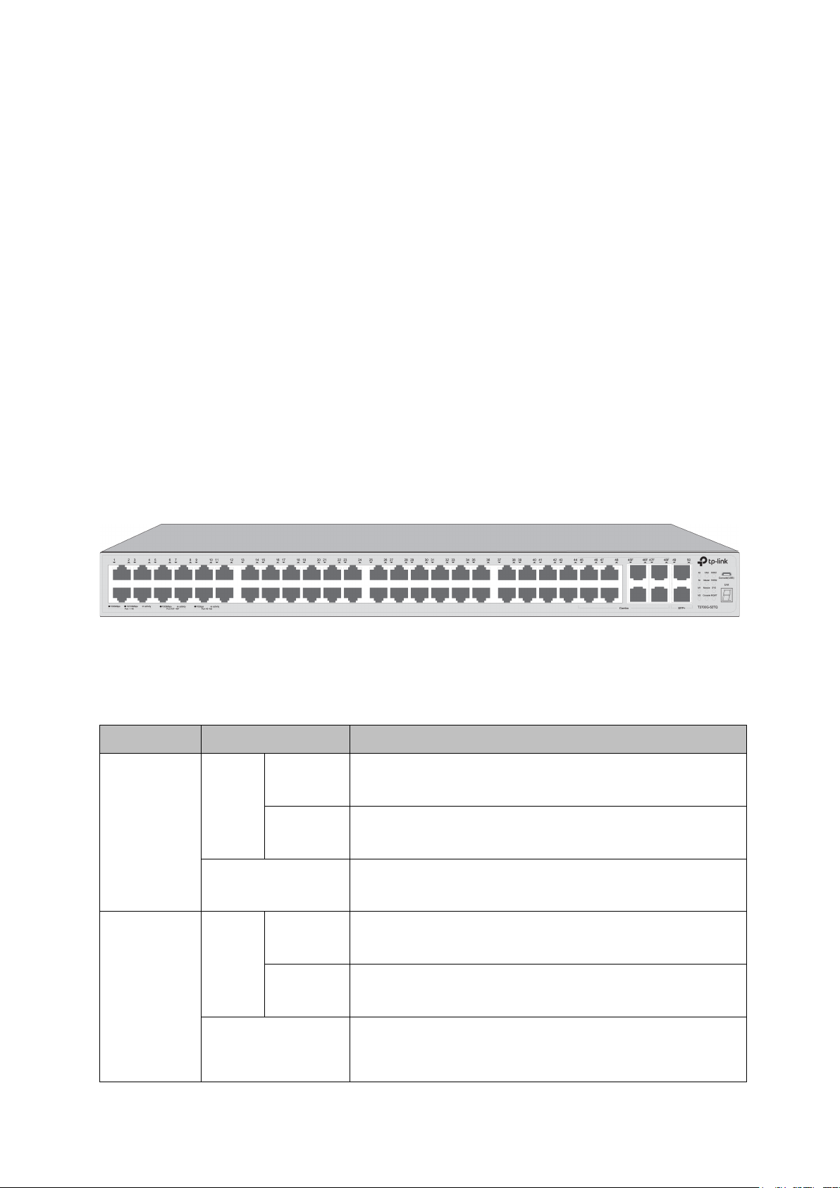
2.2.1 Front Panel
Figure 2-1 Front Panel
The following parts are located on the front panel of the switch:
LEDs
PWR1
Green
On
Yellow
Off
corresponding power slot works properly.
power supply module.
Green
On
PWR2
Yellow
Off
corresponding power slot works properly.
corresponding power slot works improperly.
power supply module.
8
Page 22

LED
Status
Indication
SYS
Flashing (green)
The switch works properly.
On/Off
The switch works improperly.
A 1000Mbps device is connected to the corresponding
Flashing
Data is being transmitted or received.
A 10/100Mbps device is connected to the
Flashing
Data is being transmitted or received.
Off
No device is connected to the corresponding port.
Green
The fan module works properly.
Yellow
The fan module works improperly.
Off
No fan module is connected to the switch.
The switch works as master in the stack system, or does
not join any stack system.
Off
An Interface Card is connected to the switch and works
properly.
An Interface Card is connected to the switch, but works
improperly.
Off
No Interface Card is connected to the switch.
On(green)
Data is being transmitted or received.
No data being transmitted or received for more than 6
minutes.
A 1000Mbps device is connected to the corresponding
Flashing
Data is being transmitted or received.
A 10/100Mbps device is connected to the
Flashing
Data is being transmitted or received.
Off
No device is connected to the corresponding port.
A 10Gbps device is connected to the corresponding
Flashing
Data is being transmitted or received.
Off
No device is connected to the corresponding port.
MGMT
FAN
Master
Green
Yellow
On(green)
On
On
On
port, but no activity.
corresponding port, but no activity.
The switch works as member in the stack system.
Module
Console
Link/Act
(Port 1-48)
49, 50
On(yellow)
Green
Yellow
Green
Off
On
On
On
port, but no activity.
corresponding port, but no activity.
port, but no activity.
9
Page 23
LED
Status
Indication
A 10Gbps device is connected to the corresponding
1. No Interface Card is connected.
No device is connected to the corresponding port
On
Green
Flashing
M1, M2
Off
10/100/1000Mbps RJ45 Ports: Port 1-48 designed to connect to the device with a
bandwidth of 10Mbps, 100Mbps or 1000Mbps. Each has a corresponding Link/Act LED.
SFP Port: Port 45F-48F, designed to install the SFP transceiver. These four SFP transceiver
slots are shared with the associated RJ45 ports. The associated two ports are referred as a
“Combo” port, which means they cannot be used simultaneously, otherwise only RJ45 port
works. The SFP ports support 1000M SFP module connection only.
SFP+ Port: Port 49-50, designed to install the 10Gbps SFP+ transceiver or SFP+ cables.
T3700G-52TQ also provides an interface card slot on the rear panel to install the expansion
card (TX432 of TP-Link for example). If TX432 is installed, you get another two 10Gbps
SFP+ ports.
port of the Interface Card, but no activity.
Data is transmitting or received.
2.
of the Interface Card.
Micro-USB Console Port: Designed to connect with the USB port of a computer for
monitoring and configuring the switch. The switch has an RJ-45 console port and a
micro-USB console port available. Console input is active on only one console port at a time.
By default, the micro-USB connector takes precedence over the RJ-45 connector.
Unit ID LED: Designed to display the stack Unit ID of the switch. For the switch that does
not join any stack system, it displays its default Unit ID. To modify the default unit number,
please logon to the GUI of the switch and go to Stack→Stack Management→Stack Config
page.
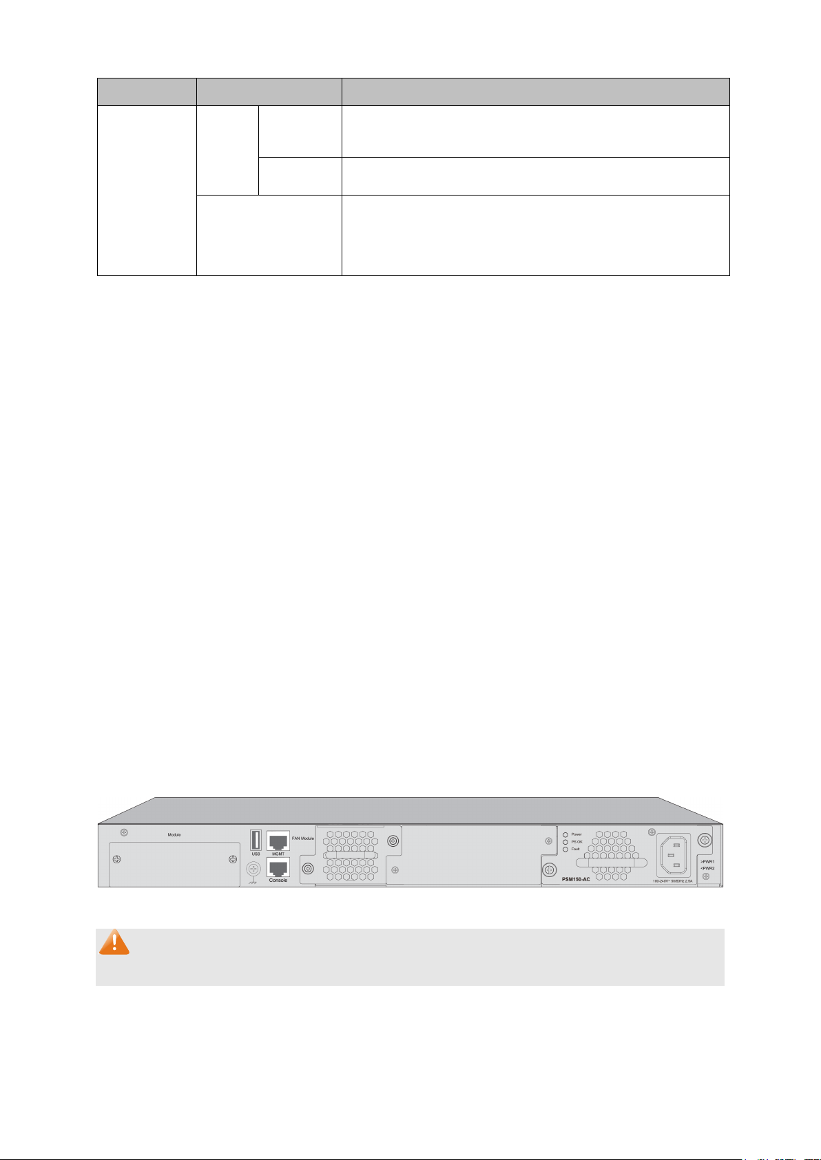
2.2.2 Rear Panel
The rear panel of T3700G-52TQ is shown as the following figure.
Figure 2-2 Rear Panel (1)
Note:
The Interface Card Slot and Power Supply Module2 are shipped with protective covers.
Interface Card Slot: Designed to extend the interfaces. You can select an Interface Card
(TX432 of TP-Link for example) for your switch if needed.
10
Page 24
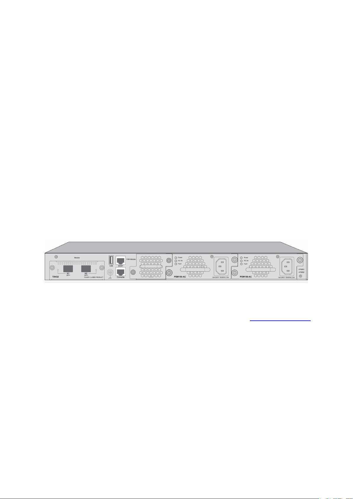
Grounding Terminal: T3700G-52TQ already comes with Lightning Protection Mechanism.
You can also ground the switch through the PE (Protecting Earth) cable of AC cord or with
Ground Cable. For detailed information, please refer to Installation Guide.
USB 2.0 Interface: USB 2.0 interface is used to connecting peripheral equipment.
Management Port: Designed to connect to the device with a bandwidth of 10Mbps,
100Mbps or 1000Mbps. It has a corresponding MGMT LED on the front panel. You need
assign an IP address for the port to manage the switch.
RJ-45 Console Port: Designed to connect with the serial port of a computer or terminal for
monitoring and configuring the switch. The switch has an RJ-45 console port and a
micro-USB console port available. Console input is active on only one console port at a time.
By default, the micro-USB connector takes precedence over the RJ-45 connector.
Power Supply Module 1/2: One AC Power Supply Module PSM150-AC has been installed in
the switch. The malfunctioned PSM150-AC can be replaced with a TP-Link power supply
module of the same model. Its input voltage is 100-240V~ 50/60Hz.
The AC Power Supply Module is fully hot swappable, helping to ensure no system
interruption during installation or replacement. For how to install/remove the Power Supply
Module, please refer to Installation Guide.
With all the protective covers removed, and the Interface Card (TX432) & Power Supply Module
(PSM150-AC) inserted, the rear panel of T3700G-52TQ is shown as the following figure.
Figure 2-3 Rear Panel (2)
Return to CONTENTS
11
Page 25
Chapter 3 Login to the Switch
3.1 Login
1) To access the configuration utility, open a web-browser and type in the default address
http://192.168.0.1 in the address field of the browser, then press the Enter key.
Figure 3-1 Web-browser
Tips:
To log in to the switch, the IP address of your PC should be set in the same subnet addresses
of the switch. The IP address is 192.168.0.x ("x" is any number from 2 to 254), Subnet Mask is
255.255.255.0.
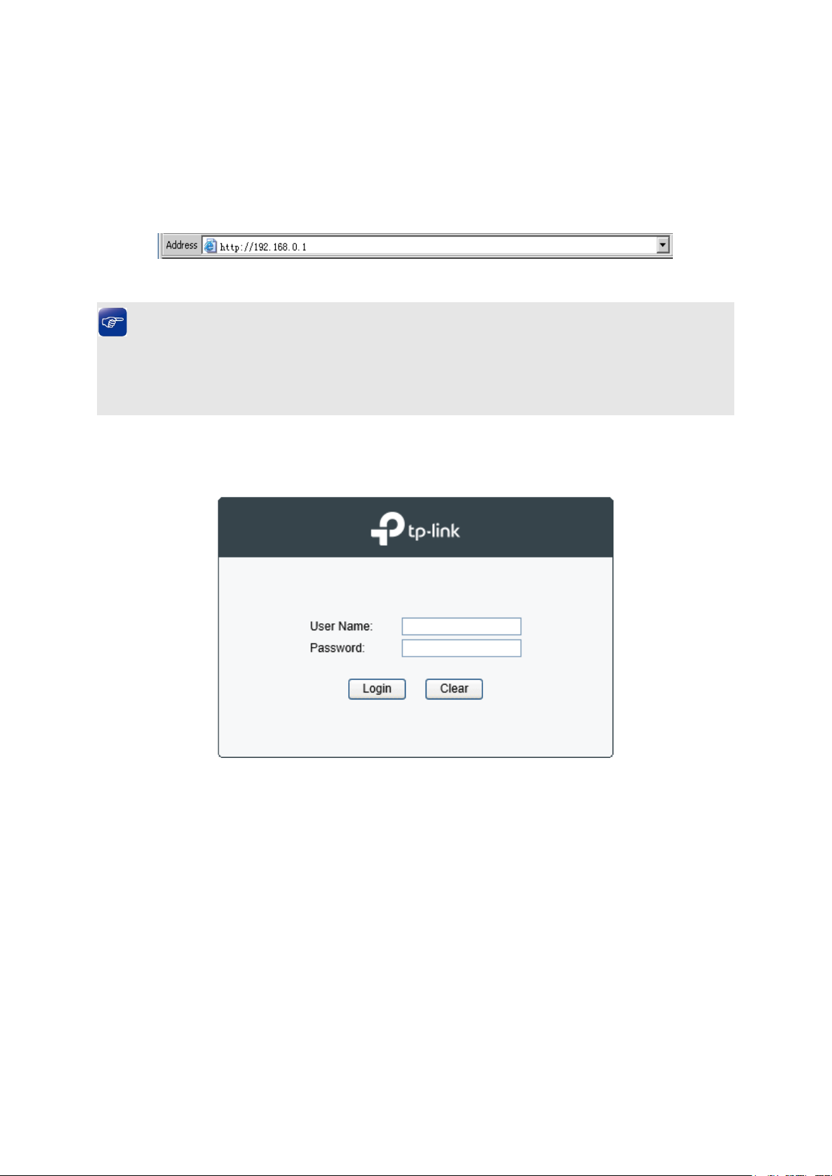
2) After a moment, a login window will appear, as shown in Figure 3-2. Enter admin for the User
Name and Password, both in lower case letters. Then click the Login button or press the
Enter key.
Figure 3-2 Login
3.2 Configuration
After a successful login, the main page will appear as Figure 3-3, and you can configure the
function by clicking the setup menu on the left side of the screen.
12
Page 26
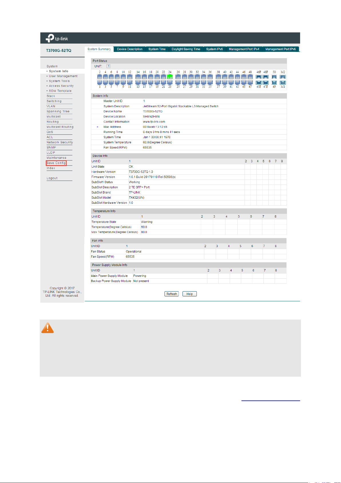
Figure 3-3 Main Setup-Menu
Note:
Clicking Apply can only make the new configurations effective before the switch is rebooted. If
you want to keep the configurations effective even the switch is rebooted, please click Save
Config. You are suggested to click Save Config before cutting off the power or rebooting the
switch to avoid losing the new configurations.
Return to CONTENTS
13
Page 27

Chapter 4 System
The System module is mainly for system configuration of the switch, including five submenus:
System Info, User Management, System Tools, Access Security and SDM Template.
4.1 System Info
The System Info, mainly for basic properties configuration, can be implemented on System
Summary, Device Description, System Time, Daylight Saving Time, System IPv6,
Management Port IPv4 and Management Port IPv6 pages.
4.1.1 System Summary
On this page you can view the port connection status and the system information.
The port status diagram shows the working status of 44 10/100/1000Mbps RJ45 ports, 4
1000Mbps SFP ports and 4 10000Mbps SFP+ ports of the switch. Ports 45, 46, 47 and 48 are
Combo ports with SFP ports labeled 45F, 46F, 47F and 48F.
14
Page 28
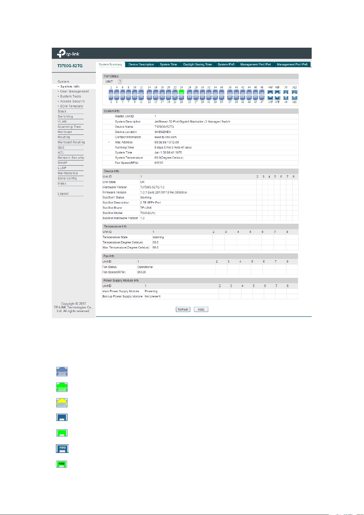
Indicates the 1000Mbps port is not connected to a device.
Indicates the 1000Mbps port is at the speed of 10Mbps or 100Mbps.
Indicates the SFP port is at the speed of 1000Mbps.
Indicates the SFP+ port is at the speed of 10000Mbps.
Choose the menu System → System Info → System Summary to load the following page.
Port Status
UNIT:
Indicates the SFP+ port is not connected to a device.
Figure 4-1 System Summary
Select the unit ID of the desired member in the stack.
Indicates the 1000Mbps port is at the speed of 1000Mbps.
Indicates the SFP port is not connected to a device.
15
Page 29
Port:
Displays the port number of the switch.
Type:
Displays the type of the port.
Rate:
Displays the maximum transmission rate of the port.
Status:
Displays the connection status of the port.
Select Rx to display the bandwidth utilization of receiving
packets on this port.
Select Tx to display the bandwidth utilization of sending packets
on this port.
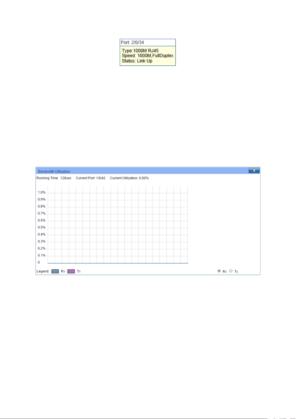
When the cursor moves on the port, the detailed information of the port will be displayed.
Figure 4-2 Port Information
Port Info
Click a port to display the bandwidth utilization on this port. The actual rate divided by
theoretical maximum rate is the bandwidth utilization.
Figure 4-3 displays the bandwidth
utilization monitored every four seconds. Monitoring the bandwidth utilization on each port
facilitates you to monitor the network traffic and analyze the network abnormities.
Figure 4-3 Bandwidth Utilization
Bandwidth Utilization
Rx:
Tx:
4.1.2 Device Description
On this page you can configure the description of the switch, including device name, device
location and system contact.
Choose the menu System→ System Info→ Device Description to load the following page.
16
Page 30
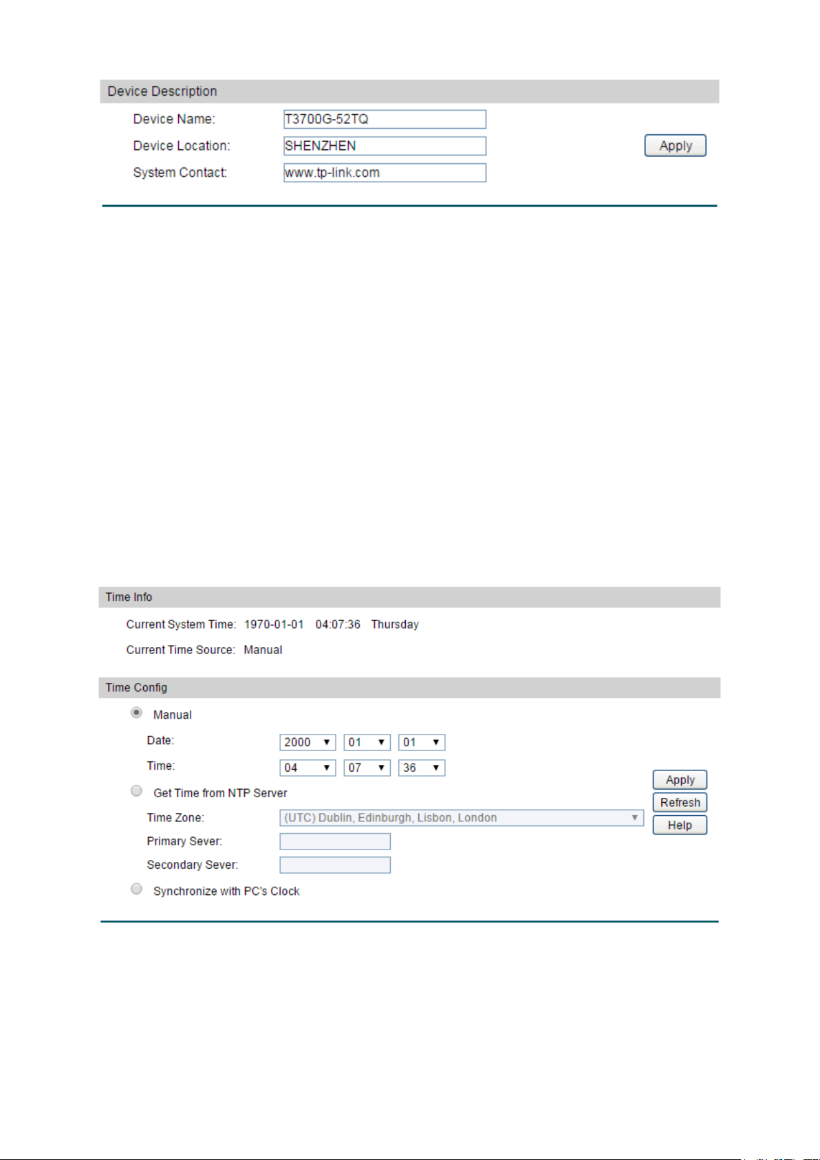
Device Name:
Enter the name of the switch.
Device Location:
Enter the location of the switch.
System Contact:
Enter your contact information.
Current System Time:
Displays the current date and time of the switch.
Figure 4-4 Device Description
The following entries are displayed on this screen:
Device Description
4.1.3 System Time
System Time is the time displayed while the switch is running. On this page you can configure the
system time and the settings here will be used for other time-based functions like ACL.
You can manually set the system time, get UTC automatically if it has connected to an NTP
server or synchronize with PC’s clock as the system time.
Choose the menu System → System Info →System Time to load the following page.
The following entries are displayed on this screen:
Time Info
Figure 4-5 System Time
17
Page 31

Current Time Source:
Displays the current time source of the switch.
When this option is selected, you can set the date and time
manually.
Get Time from NTP
When this option is selected, you can configure the time zone
nd the IP Address for the NTP Server. The switch will get
ddress for
ng time from NTP
server.
clock is
utilized.
Time Config
Manual:
Server:
a
UTC automatically if it has connected to an NTP Server.
Time Zone: Select your local time.
Primary/Secondary NTP Server: Enter the IP a
the NTP Server.
Update Rate: Specify the rate fetchi
Synchronize with
When this option is selected, the administrator PC’s
PC’S Clock:
Note:
1. The system time will be restored to the default when the switch is restarted and you need to
reconfigure the system time of the switch.
2. When Get Time from NTP Server is selected and no time server is configured, the switch will
get time from the time server of the Internet if it has connected to the Internet.
4.1.4 Daylight Saving Time
Here you can configure the Daylight Saving Time of the switch.
Choose the menu System → System Info → Daylight Saving Time to load the following page.
Figure 4-6 Daylight Saving Time
18
Page 32

DST Status:
Enable or disable DST.
USA: Second Sunday in March, 02:00 ~ First Sunday in
Europe: Last Sunday in March, 01:00 ~ Last Sunday in
October, 01:00.
ST configuration in recurring mode. This
Offset: Specify the time adding in minutes when Daylight
Start/End Time: Select starting time and ending time of
Daylight Saving Time.
T configuration in Date mode. This
Offset: Specify the time adding in minutes when Daylight
Start/End Time: Select starting time and ending time of
Daylight Saving Time.
The following entries are displayed on this screen:
DST Config
Predefined Mode: Select a predefined DST configuration:
November, 02:00.
Recurring Mode: Specify the D
configuration is recurring in use:
Saving Time comes.
Date Mode: Specify the DS
configuration is one-off in use:
Saving Time comes.
Note:
When the DST is disabled, the predefined mode, recurring mode and date mode cannot be
configured.
4.1.5 System IPv6
On this page you can configure IPv6 address on the switch and login the switch through the
address to access the IPv6 applications. Internet Protocol Version 6 (IPv6), also called IP next
generation (IPng), is designed by the Internet Engineering Task Force (IETF) as the successor to
Internet Protocol Version 4 (IPv4). The significant difference between IPv6 and IPv4 is that IPv6
increases the IP address size from 32 bits to 128 bits.
Choose the menu System → System Info → System IPv6 to load the following page.
19
Page 33

IPv6:
Enable or disable IPv6 function globally on the switch.
Choose the interface ID to set IPv6 function. You can set
interface type as VLAN Port or Routed Port.
When this option is selected, the switch will
generate a link-local address automatically.
Link-local Address:
Enter a link-local address.
Figure 4-7 System IPv6
The following entries are displayed on this screen:
Gobal Config
Interface:
Link-local Address Config
Config Mode: Select the link-local address configuration mode.
Manual: When this option is selected, you should assign
a link-local address manually.
Auto:
20
Page 34

local address may be newly
local address is duplicate.
It is illegal to access the switch using the IPv6 address
(including link-local and global address).
Enable global address
auto configuration via
When this option is enabled, the switch automatically
configures a global address and other information according
configuration parameters
from the received RA (Router Advertisement) message.
Enable global address
auto configuration via
DHCPv6 Server:
When this option is enabled, the system will try to obtain the
You can select the global address format according to your
64: Indicates that you only need to specify an
64: Indicates that you have to specify an intact
global address.
64, please input the address
prefix here, otherwise, please input an intact IPv6 address
here.
Select the desired entry to delete or modify the
corresponding global address.
Global Address:
Modify the global address.
Prefix Length:
Modify the prefix length of the global address.
Indicates that the corresponding address is
Indicates that the corresponding address is
created automatically using the RA message or obtained
from the DHCPv6 Server.
Preferred Lifetime:
Displays the preferred time of the global address.
Status: Displays the status of the link-local address.
Normal: Indicates that the link-local address is normal.
Try: Indicates that the link-
configured.
Repeat: Indicates that the link-
Global Address Autoconfig via RA Message
RA message:
Global Address Autoconfig via DHCPv6 Server
to the address prefix and other
global address from the DHCPv6 Server.
Add a Global Address Manually
Address Format:
requirements.
EUI-
address prefix, and then the system will create a global
address automatically.
Not EUI-
Global Address: When selecting the mode of EUI-
Global Address Table
Select:
Type:
Displays the configuration mode of the global address.
Manual:
configured manually.
Auto:
21
Page 35

Valid Lifetime:
Displays the valid time of the global address.
icates that the global address may be newly
Indicates that the corresponding address is
duplicate. It is illegal to access the switch using this
address.
Specify IPv4 Address allocate mode of the management port.
DHCP: Allocated through DHCP.
ID (Option 61) is used by DHCP clients to
specify their unique identifier. This value is expected to be
unique for all clients in an administrative domain.
Specify the IP address of the interface when the
Management Port Configuration Protocol is None.
Specify the Subnet Mask of the interface when the
Management Port Configuration Protocol is None.
Status:
Displays the status of the global address.
Normal: Indicates that the global address is normal.
Try: Ind
configured.
Repeat:
4.1.6 Management Port IPv4
The Management Port is a dedicated Ethernet port for out-of-band management of the device.
Traffic on this port is segregated from operational network traffic on the switch ports and
cannot be switched or routed to the operational network. Use this page to configure network
information on the management port.
Choose the menu System → System Info → Management Port IPv4 to load the following page.
Figure 4-8 Management Port IPv4
The following entries are displayed on this screen:
IPv4 Protocol Configuration
IPv4 Protocol:
None: Setup manually.
DHCP Client-ID: The DHCP Client-
IP Address:
Subnet Mask:
22
Page 36

Specify the Gateway of the interface when the Management
Port Configuration Protocol is None.
Select:
Select the interfaces to modify or delete.
nt port.
DHCP: Allocated through DHCP.
Specify the IP address of the interface when the
Management Port Configuration Protocol is None.
Specify the Subnet Mask of the interface when the
Management Port Configuration Protocol is None.
Specify the Gateway of the interface when the Management
Port Configuration Protocol is None.
Status:
Displays interface current working status: up or down.
Gateway:
IPv4 Address List
IPv4 Protocol: Specify IPv4 Address allocate mode of the manageme
None: Setup manually.
IP Address:
Subnet Mask:
Gateway:
4.1.7 Management Port IPv6
The Management Port is a dedicated Ethernet port for out-of-band management of the device.
Traffic on this port is segregated from operational network traffic on the switch ports and
cannot be switched or routed to the operational network. Use this page to configure IPv6
network information on the management port.
Choose the menu System → System Info → Management Port IPv6 to load the following page.
Figure 4-9 Management Port IPv6
23
Page 37

Enable or disable IPv6 function globally on the management
port.
Specify IPv6 network information allocate mode of the
DHCP: Allocated through DHCP.
(if enabled)
when sending messages to the DHCPv6 server.
Choose whether to allow to enable the IPv6 stateless
address autoconfiguration mode via the RA message on the
management port.
You can select the IPv6 address format according to your
64: Indicates that you only need to specify an
n intact
IPv6 address.
64, please input the address
prefix here, otherwise, please input an intact IPv6 address
here.
IPv6 Gateway:
Choose whether to set the IPv6 Gateway Address.
Address:
Select:
Select the interfaces to modify or delete.
IPv6 Address Type:
Displays IPv6 Address type: Link Local, Global or Router.
IPv6 Prefix:
Displays the IPv6 prefix.
Prefix Length:
Displays the prefix length of IPv6 Address.
The following entries are displayed on this screen:
IPv6 Configuration
IPv6:
IPv6 Protocol:
management port.
None: Setup manually.
DHCPv6 Client DUID: The client identifier used by the DHCPv6 client
AutoConfig:
Add a IPv6 Address
Address Format:
requirements.
EUI-
address prefix, and then the system will create a IPv6
address automatically.
Not EUI-64: Indicates that you have to specify a
IPV6 Address: When selecting the mode of EUI-
IPv6 Gateway Configuration
IPv6 Gateway
IPv6 Address List
Please input the IPv6 gateway address here.
4.2 User Management
User Management functions to configure the user name and password for users to log on to
the Web management page with a certain access level so as to protect the settings of the
switch from being randomly changed.
24
Page 38

User Name:
Create a name for users’ login.
Guest only can view the settings without the right to
Admin can edit, modify and view all the settings of
different functions.
The User Management function can be implemented on User Table and User Config pages.
4.2.1 User Table
On this page you can view the information about the current users of the switch.
Choose the menu System → User Management → User Table to load the following page.
Figure 4-10 User Table
4.2.2 User Config
On this page you can configure the access level of the user to log on to the Web management
page. The switch provides two access levels: Guest and Admin. The guest only can view the
settings without the right to configure the switch; the admin can configure all the functions of
the switch. The Web management pages contained in this guide are subject to the admin’s login
without any explanation.
Choose the menu System → User Management → User Config to load the following page.
Figure 4-11 User Config
The following entries are displayed on this screen:
User Info
Access Level: Select the access level to login.
Guest:
edit and modify.
Admin:
25
Page 39

Password:
Type a password for users’ login.
Confirm Password:
Retype the password.
Select the desired entry to delete the corresponding user
The current user information
cannot be deleted.
User Name
and Access Level:
button of the desired entry, and you can edit the
corresponding user information. After modifying the settings,
button to make the modification
effective.
User Table
Select:
information. It is multi-optional.
User ID,
Operation:
Displays the current user ID, user name and access level.
Click the Edit
please click the Apply
4.3 System Tools
The System Tools function, allowing you to manage the configuration file of the switch, can be
implemented on Boot Config, Config Restore, Config Backup, Firmware Upgrade, System
Reboot and System Reset pages.
4.3.1 Boot Config
On this page you can configure the boot file and the configuration file of the switch. When the
switch is powered on, it will start up with the startup image. If the startup fails, the switch will try
to start up with the backup image. If this startup fails too, the switch will changes to bootutil
state, in which circumstance the switch’s Web interface is unavailable and you can enter into
the bootutil menu of the switch through the console connection.
When the startup process is finished, the switch will read the startup-config file. If it fails, the
switch will try to read the backup-config file. If it fails too, the switch will be restored to factory
settings.
Choose the menu System → System Tools → Boot Config to load the following page.
26
Page 40

Select:
Select the unit(s).
Unit:
Displays the unit ID.
Image:
Next Startup Image:
Select the next startup image.
Backup Image:
Select the backup boot image.
Image Name:
The name of the image.
Flash Version:
The flash version of the image.
Software Version:
The software version of the image.
Figure 4-12 Boot Config
The following entries are displayed on this screen:
Boot Table
Current Startup
Image Table
Displays the current startup image.
4.3.2 Config Restore
On this page you can upload a backup configuration file to restore your switch to this previous
configuration.
Choose the menu System → System Tools → Config Restore to load the following page.
27
Page 41

It will take effect after the switch automatically reboots.
button to save the current configuration as a
u are suggested to take this measure
before upgrading.
Figure 4-13 Config Restore
The following entries are displayed on this screen:
Config Restore
Import: Click the Import button to restore the backup configuration file.
Note:
1. It will take a few minutes to restore the configuration. Please wait without any operation.
2. To avoid any damage, please don’t power down the switch while being restored.
3. After the configuration file is restored successfully, the device will reboot to make the
configuration change effective.
4. Wrong uploaded configuration file may cause the switch unmanaged.
4.3.3 Config Backup
On this page you can download the current configuration of the specified unit in the stack and
save it as a file to your computer for your future configuration restore.
Choose the menu System → System Tools → Config Backup to load the following page.
Figure 4-14 Config Backup
The following entries are displayed on this screen:
Config Backup
Export: Click the Export
file to your computer. Yo
28
Page 42

Note:
1. It will take a few minutes to backup the configuration. Please wait without any operation.
2. Check the checkbox to copy running-config to startup-config before exporting the
startup-config.
4.3.4 Firmware Upgrade
The switch system can be upgraded via the Web management page. To upgrade the system is
to get more functions and better performance. Go to http://www.tp-link.com
updated firmware.
Choose the menu System → System Tools → Firmware Upgrade to load the following page.
to download the
Figure 4-15 Firmware Upgrade
Note:
1. Don’t interrupt the upgrade.
2. Upgrading the firmware will only upgrade the backup image.
3. You are suggested to backup the configuration before upgrading.
4. Please select the proper software version matching with your hardware to upgrade.
5. To avoid damage, please don't turn off the device while upgrading.
6. After upgrading, the device will reboot automatically.
4.3.5 System Reboot
On this page you can reboot the specified unit switch in the stack and return to the login page.
Please save the current configuration before rebooting to avoid losing the configuration
unsaved
Choose the menu System → System Tools → System Reboot to load the following page.
29
Page 43

Figure 4-16 System Reboot
Note:
To avoid damage, please don't turn off the device while rebooting.
4.3.6 System Reset
On this page you can reset the specified unit in the stack to the default. All the settings will be
cleared after the switch is reset.
Choose the menu System → System Tools → System Reset to load the following page.
Figure 4-17 System Reset
Note:
The System Reset option will restore the configuration to default and your current settings will
be lost.
4.4 Access Security
Access Security provides different security measures for the remote login so as to enhance
the configuration management security. It can be implemented on Access Control, HTTP
Config, HTTPS Config, SSH Config and Telnet Config pages.
4.4.1 Access Control
On this page you can control the users logging on to the Web management page to enhance
the configuration management security. The definitions of Admin and Guest refer to
Management. This function only applies to Web, SNMP, Telnet, SSL and SSH.
Choose the menu System → Access Security → Access Control to load the following page.
4.2 User
30
Page 44

Select the control mode for users to log on to the Web
range of the users
Select this option to limit the MAC Address of
managing the switch.
Access Interface:
Select the interface for Access Control to apply.
These fields can be available for configuration only when
range
you set here are allowed for managing the switch.
The field can be available for configuration only when
based mode is selected. Only the user with this MAC
Address you set here is allowed for managing the switch.
ion only when
based mode is selected. Only the users connected to
these ports you set here are allowed for managing the switch.
Figure 4-18 Access Control
The following entries are displayed on this screen:
Access Control Config
Control Mode:
management page.
Disable: Select to disable Access Control function.
IP-based: Select this option to limit the IP-
for managing the switch.
MAC-based:
the users for managing the switch.
Port-based: Select this option to limit the ports for
IP Address& Mask:
IP-based mode is selected. Only the users within the IP-
MAC Address:
MAC-
Port: The field can be available for configurat
Port-
4.4.2 HTTP Config
With the help of HTTP (Hyper Text Transfer Protocol), you can manage the switch through a
standard browser. The standards development of HTTP was coordinated by the Internet
Engineering Task Force and the World Wide Web Consortium.
On this page you can configure the HTTP function.
31
Page 45

HTTP:
Enable or disable the HTTP function on the switch.
Hard Timeout:
Configure hard timeout of HTTP sessions.
Soft Timeout:
Configure soft timeout of HTTP sessions.
Maximum Sessions:
Configure maximum allowable number of HTTP sessions.
Choose the menu System → Access Security → HTTP Config to load the following page.
Figure 4-19 HTTP Config
The following entries are displayed on this screen
Global Config
Session Config
:
4.4.3 HTTPS Config
SSL (Secure Sockets Layer), a security protocol, is to provide a secure connection for the
application layer protocol (e.g. HTTP) communication based on TCP. SSL is widely used to
secure the data transmission between the Web browser and servers. It is mainly applied
through ecommerce and online banking.
SSL mainly provides the following services:
1. Authenticate the users and the servers based on the certificates to ensure the data are
transmitted to the correct users and servers;
2. Encrypt the data transmission to prevent the data being intercepted;
3. Maintain the integrality of the data to prevent the data being altered in the transmission.
Adopting asymmetrical encryption technology, SSL uses key pair to encrypt/decrypt
information. A key pair refers to a public key (contained in the certificate) and its corresponding
private key. By default the switch has a certificate (self-signed certificate) and a corresponding
private key. The Certificate/Key Download function enables the user to replace the default key
pair.
After SSL is effective, you can log on to the Web management page via https://192.168.0.1
the first time you use HTTPS connection to log into the switch with the default certificate, you
will be prompted that “The security certificate presented by this website was not issued by a
. For
32
Page 46

HTTPS:
Enable or disable the HTTPS function on the switch.
trusted certificate authority” or “Certificate Errors”. Please add this certificate to trusted
certificates or continue to this website.
The switch also supports HTTPS connection for IPv6. After configuring an IPv6 address (for
example, 3001::1) for the switch, you can log on to the switch’s Web management page via
https://[3001::1].
On this page you can configure the HTTPS function.
Choose the menu System → Access Security → HTTPS Config to load the following page.
The following entries are displayed on this screen
Global Config
Figure 4-20 HTTPS Config
:
33
Page 47

isable Secure Sockets Layer Version 3.0. By default,
it’s enabled.
isable Transport Layer Security Version 1.0. By
default, it’s enabled.
bit encryption and
MD5 for message digest. By default, it’s enabled.
bit encryption and
SHA for message digest. By default, it’s enabled.
CBC for message
ryption and SHA for message digest. By
default, it’s enabled.
CBC
for message encryption and SHA for message
digest. By default, it’s enabled.
Hard Timeout:
Configure hard timeout of HTTP sessions.
Soft Timeout:
Configure soft timeout of HTTP sessions.
Maximum Sessions:
Configure maximum allowable number of HTTP sessions.
The status of SSL certificate and key file (PEM Encoded) on the
device, which might be Present or Absent.
to download to the switch. The
certificate must be BASE64 encoded.
Select the desired key to download to the switch. The key must
be BASE64 encoded.
SSL Version 3: Enable or d
TLS Version 1: Enable or d
CipherSuite Config
RSA_WITH_RC4_128_MD5: Key exchange with RC4 128-
RSA_WITH_RC4_128_SHA: Key exchange with RC4 128-
RSA_WITH_DES_CBC_SHA: Key exchange with DES-
enc
RSA_WITH_3DES_EDE_CBC_SHA: Key exchange with 3DES and DES-EDE3-
Session Config
Certificate and Key Management
You can get the status of the DSA and RSA keys, which can also be generated or deleted
here with the Generate and Delete buttons.
Certificate and Key:
Certificate Download
Certificate File: Select the desired certificate
Key Download
Key File:
Note:
1. HTTPS function can not be enabled until the SSL certificate and key are present.
2. The SSL certificate and key downloaded must match each other; otherwise the HTTPS
connection will not work.
34
Page 48

3. To establish a secured connection using https, please enter https:// into the URL field of
the browser.
4. It may take more time for https connection than that for http connection, because https
connection involves authentication, encryption and decryption etc.
4.4.4 SSH Config
As stipulated by IETF (Internet Engineering Task Force), SSH (Secure Shell) is a security
protocol established on application and transport layers. SSH-encrypted-connection is similar
to a telnet connection, but essentially the old telnet remote management method is not safe,
because the password and data transmitted with plain-text can be easily intercepted. SSH can
provide information security and powerful authentication when you log on to the switch
remotely through an insecure network environment. It can encrypt all the transmission data and
prevent the information in a remote management being leaked.
Comprising server and client, SSH has two versions, V1 and V2 which are not compatible with
each other. In the communication, SSH server and client can auto-negotiate the SSH version
and the encryption algorithm. After getting a successful negotiation, the client sends
authentication request to the server for login, and then the two can communicate with each
other after successful authentication. This switch supports SSH server and you can log on to
the switch via SSH connection using SSH client software.
SSH key can be downloaded into the switch. If the key is successfully downloaded, the
certificate authentication will be preferred for SSH access to the switch.
35
Page 49

SSH:
Enable or disable SSH function.
Protocol V1:
Enable or disable SSH V1 to be the supported protocol.
Protocol V2:
Enable or disable SSH V2 to be the supported protocol.
Specify the idle timeout time. The system will automatically
release the connection when the time is up. The default time is
120 seconds.
Specify the maximum number of the connections to the SSH
ection will be established when the number
of the connections reaches the maximum number you set. The
default value is 5.
Choose the menu System → Access Security → SSH Config to load the following page.
Figure 4-21 SSH Config
The following entries are displayed on this screen
Global Config
Idle Timeout:
Max Connect:
server. No new conn
:
36
Page 50

CBC algorithm of
SSH.
CBC algorithm of
SSH.
CBC algorithm of
SSH.
CBC algorithm of
SSH.
CBC algorithm of
SSH.
3DES-CBC:
Select the checkbox to enable the 3DES-CBC algorithm of SSH.
ithm of
SSH.
MD5 algorithm of
SSH.
which might be Present or Absent.
2 RSA key file (PEM Encoded)
on the device, which might be Present or Absent.
file to
the switch.
Select the type of SSH Key to download. The switch supports
two types: SSH-2 RSA/DSA and SSH-1 RSA.
Please ensure the key length of the downloaded file is in the
range of 512 to 3072 bits.
button to download the desired key file to
the switch.
Encryption Algorithm
Configure SSH encryption algorithms.
AES128-CBC:
Select the checkbox to enable the AES128-
AES192-CBC: Select the checkbox to enable the AES192-
AES256-CBC: Select the checkbox to enable the AES256-
Blowfish-CBC: Select the checkbox to enable the Blowfish-
Cast128-CBC: Select the checkbox to enable the Cast128-
Data Integrity Algorithm
Configure SSH data integrity algorithms.
HMAC-SHA1:
Select the checkbox to enable the HMAC-SHA1 algor
HMAC-MD5: Select the checkbox to enable the HMAC-
Key Management
You can get the status of the DSA and RSA keys, which can also be generated or deleted
here with the Generate and Delete buttons.
DSA:
The status of SSH-2 DSA key file (PEM Encoded) on the device,
RSA: The status of SSH-1 RSA or SSH-
Download: Click the Download button to download the desired key
Key Download
Key Type:
Key File:
Download: Click the Download
37
Page 51

Note:
1. It will take a long time to download the key file. Please wait without any operation.
2. After the Key File is downloaded, the user's original key of the same type will be replaced.
Application Example for SSH:
Network Requirements
1. Log on to the switch via password authentication using SSH and the SSH function is
enabled on the switch.
2. PuTTY client software is recommended.
Configuration Procedure
1. Open the software to log on to the interface of PuTTY. Enter the IP address of the switch
into Host Name field; keep the default value 22 in the Port field; select SSH as the
Connection type.
38
Page 52

Telnet:
Enable or disable Telnet function globally on the switch.
2. Click the Open button in the above figure to log on to the switch. Enter the login user name
and password, and then you can continue to configure the switch.
4.4.5 Telnet Config
On this page you can enable or disable Telnet function globally on the switch.
Choose the menu System → Access Security → Telnet Config to load the following page.
Figure 4-22 Access Control
The following entries are displayed on this screen:
Global Config
4.5 SDM Template
SDM (Switch Database Management) provides different templates for users to efficiently
manage the hardware TCAM resources. Users can select the appropriate template according
to the application environment.
4.5.1 SDM Template Config
On this page you can configure and view the SDM templates on the switch.
39
Page 53

ID:
template that will become active after a
reboot.
Configure the SDM template that will become active after the
next reboot.
SDM Template:
Displays the template name.
IPv4 Address Resolution
Protocol (ARP) cache for routing interfaces.
IPv4 Unicast Routes:
The maximum number of IPv4 unicast forwarding table entries.
The maximum number of next hops that can be installed in the
IPv4 and IPv6 unicast forwarding tables.
The maximum number of IPv4 multicast forwarding table
entries.
The maximum number of IPv6 multicast forwarding table
entries.
Choose the menu System → SDM Template → SDM Template Config to load the following
page.
Figure 4-23 SDM Template Config
Select Options
Current Template
Displays the SDM template currently in use.
Next Template ID: Displays the SDM
Select Next
Template:
Template Table
ARP Entries: The maximum number of entries in the
ECMP Next Hops:
IPv4 Multicast
Routes:
IPv6 Multicast
Routes:
Return to CONTENTS
40
Page 54

Chapter 5 Stack
The stack technology is to connect multiple stackable devices through their stack ports,
forming a stack which works as a unified system and presents as a single entity to the network
in Layer 2 and Layer 3 protocols. It enables multiple devices to collaborate and be managed as
a whole, which improves the performance and simplifies the management of the devices
efficiently.
Advantages
The stack delivers the following benefits:
1. Simplified management. After stack establishment, the user can log in the stack system
through any stack ports of stackable devices, and manage it as a single device. You only
need to configure the stack system once instead of operating repetitive configuration on
multiple devices. Various ways such as CONSOLE, SNMP, TELNET and WEB are available
for users to manage the stack.
2. High reliability. The stack is highly reliable in following aspects:
1) The stack system is comprised of multiple devices among which one member device
works as the stack master to take charge of the operation, management and
maintenance of the stack, while the other stack members process services and keep a
copy configuration file in accordance with the master for providing backup
simultaneously. Once the stack master becomes unavailable, the remaining stack
members elect a new master among themselves instantly and automatically, which can
ensure uninterrupted services and furthermore making 1:N backup feasible. Due to the
real-time configuration and data synchronization being strictly executed, the new
master can take over the previous master to manage and maintain the stack system
smoothly without affecting its normal operation.
2) Distributed LACP (Link Aggregation Control Protocol) supports link aggregation across
devices. Since the whole stack system presents as a single device on the network,
external devices can implement LACP with the stack system by connecting to several
stack member devices simultaneously. Among the links between the stack system and
external devices, load distribution and backup can be realized to increase the reliability
of the stack system and to simplify dramatically the network topology as Figure 5-1
shows.
41
Page 55

Figure 5-1 Distributed LACP
In a ring connected stack, it can still operate normally by transforming into a daisy
chained stack when link failure occurs, which further ensures the normal operation of
load distribution and backup across devices and links as Figure 5-2 shows.
Figure 5-2 Load Distribution and Backup across Devices
3. Network scalability. Each member device in the stack system is able to process protocol
packets and forward data individually, which enables you to increase the port number and
bandwidth of the stack system by adding new member devices. The users are free to add
or remove stack members without affecting the normal running of the stack, which enables
them to protect the existed resources furthest during network upgrades.
42
Page 56

Application Diagram
Figure 5-3 Application Diagram
Stack Introduction
1. Stack Elements
1) Stack Role
Each device in the stack system is called stack member. Each stack member processes
services packets and plays a role which is either master or member in the stack system.
The differences between master and member are described as below:
• Master: Indicates the device is responsible for managing the entire stack system.
• Member: Indicates the device provides backup for the master. If the master fails, the
stack will elect a new master from the remaining members to succeed the previous
master.
2) Stack Event
Stack event indicates the global events which might happen during stack operation
process, with two options:
• Merge: It occurs when two independent stacks merge into one stack because of stack
link establishment, as shown in the following figure:
Figure 5-4 Stack Merge
43
Page 57

When stack merge occurs, the previous masters compete to be the new master. The
stack members of the defeated stack will join the winner stack as a member to form a
new stack. Master will assign Unit Number to the newly joined members and compare
their configuration files. The members with different configurations files with the master
will download the configuration files of the master and re-configure.
• Split: It occurs when stack splits into two or more stacks because of stack link failures,
as shown in the following figure:
Figure 5-5 Stack Split
After stack partition occurs, each newly established stack elects their own new master
and use the MAC address of the master as its stack MAC address. However, stack
partition probably brings about routing and forwarding problems on the network since
the partitioned stacks keep operating with the previous IP address by default, which
results in same IP address being reused in the same LAN.
2. Operation Procedure
Stack management involves these four stages: Connecting the stack members, Topology
collection, Master election, and Stack management and maintenance.
1) Connecting the stack members
To establish a stack, please physically connect the stack ports of the member devices with
cables. The stack ports of T3700G-52TQ can be used for stack connection or as normal
Ethernet Gigabit port. When you want to establish a stack, the stack mode of the related
ports should be configured as "Enable". If the stack mode of the port is "Disable", then the
port will work as a normal Ethernet port.
Stack typically adopts a daisy chain topology or ring topology as shown in Figure 5-6:
Figure 5-6 Stack Connect Topology
44
Page 58

• The daisy chain topology is mainly used in a network where member devices are
distributively located.
• The ring topology is more reliable than the daisy chain topology. In a daisy chained
stack, link failure can cause stack split. While in a ring connected stack, the system is
able to operate normally with a new daisy chained topology.
Note:
Establish a stack of ring or daisy chain topology with eight T3700G-52TQ switches at most.
2) Topology Collection
Each member in the stack collects the topology of the whole stack by exchanging stack
discovery packets with its neighbors. Discovery packet carries topology information
including stack port connection status, unit number, priorities, MAC addresses, etc.
Each member keeps a local record of the known topology information. When the device
initializes, it only possesses the record of its own topology information. Periodically the
stack members send out their known topology information through the stack ports to its
neighbors. When the neighbors receive the information, they will update their local
topology information. After a period of time of broadcasting and updating information, all
the stack members can collect the complete topology information (known as topology
convergence).
Then the switch enters the master election stage.
3) Master Election
After all members have obtained topology information (known as topology convergence),
the stack enters the master election stage. A stack always has one stack master, while the
other stack members are members. Master election determines the stack role of the stack
members.
Master election is held each time the topology changes, for example, when stack merge or
split occurs, or the stack or the current master is reset.
The master is elected based on the following rules and in the order listed:
1. The switch that is currently the stack master.
2. The switch with the highest stack member priority value.
3. The switch with the lowest MAC address.
After master election, the stack forms and enters into stack management and
maintenance stage.
Note:
1. The priority value ranges from 1 to 15. The higher the value is, the more likely the
member will be elected as the master. By default, the member priority of the switch is 5.
We recommend you manually assign the highest priority value to the switch that you
prefer to be the stack master before stack establishment.
2. The switch is non-preemptible when it joins the stack in cold-start mode, and the
process is illustrated as bellow: the switch has no stack role at its start, and it sends out
45
Page 59

discovery messages to collect the topology of the current stack system. After the
topology collection, the switch obtains its role according to the rules above. The switch
will become stack member if there is already a master in the stack. The master will
resume its role even if the newly joined switch has a higher priority.
4) Stack Management and Maintenance
After the stack is established, all the stack members are integrated into a virtual device in
the network and managed by the master. The following section briefly introduces the
concepts and rules involved in stack management stage.
• Unit Number: When the stack is running, unit number is used to identify and manage
member devices. Unit number is unique in a stack system. The factory default unit
number of switch is 1. In order to keep its uniqueness, before establishing stack you are
kindly recommended to prepare a unit number assignment scheme and then manually
configure it on each member device.
During unit number assignment process, the master prioritizes the member devices
already carrying manually assigned unit number. If the unit number has not been used
by other stack members the member device will keep it. Otherwise, the unit number is
configured based on the following rules and in the order listed:
1. The device which was managed by the current master before the configuration will
resume its unit number.
2. The device with manually assigned unit number is prior to the device whose unit
number assignment mode is “Auto”.
3. The device with the highest stack member priority value.
4. The device with the lowest MAC address.
Note:
1. You can get the current unit number of the switch from the unit number LED on the
front panel of the switch.
2. When the stack is running, if you want to change the unit number manually, only the
unit numbers which have not been occupied by the other member devices are
available for you to choose from.
• Port Number Format:
The format of port number should be Unit Number/Slot Number/Port Number. Among
them:
(1) Unit Number: The default unit number of the switch is 1. If a device has joined
stack system, the unit number which the device possesses in the stack system
will be kept using as its unit number after the device leaves the stack system.
(2) Slot Number: Indicates the number of the slot the interface card is in. For
T3700G-52TQ, the front panel ports belong to slot 0. Slot number starting from 1
each represents an interface card slot.
(3) Physical Port Number: The physical port number on the switch which can be
obtained through the front panel of the switch.
46
Page 60

For instance: Port number 2/0/3 indicates the physical port3 on the switch whose unit
number is 2.
• Configuration Files Application Rules: It includes global configuration and interface
configuration two parts.
(1) The global configurations of all stack members are the same. Besides, each
member device keeps pace with the global configuration of the master device
which enables the stack system to work just like a single entity in the network. The
stack system adopts the following methods to ensure the synchronization of
global configuration files:
When the stack initializes, the master device will compare the configuration files
of each stack member and reconfigure the device whose global configuration is
different from its own, so as to ensure the global configuration of the stack
members are exactly the same.
When the stack is work normally, any global configuration of users will be
recorded to the current configuration files of master and then be synchronized to
the other members in the stack.
(2) Each stack member only saves the configuration of its own ports. Even when user
sets the configuration for all ports, the configuration will also be saved and
implemented only on the related stack member which the ports belong to.
• Stack Maintenance
Stack maintenance mainly functions to monitor the join and leave of member devices,
collect the new topology at any times and maintain the current topology.
When the stack is operating normally, packets are transmitted constantly between
stack members. The switch can quickly judge the link status of the stack port via
monitoring the response of the packets. When the switch detects the link status
changes, it will recollect system topology and update topology database to ensure the
normal operation of the stack.
The events that will change the link status of the stack port which thus affecting the
system topology include: stack member failure or leave, new member's coming, link
failure or failure recovery, etc.
When the master switch fails, the stack system elects a new master from the remaining
members to succeed the previous master.
5.1 Stack Management
Before configuring the stack, we highly recommend you to prepare the configuration planning
with a clear set of the role and function of each member device. Some configuration needs
device reboot to take effect, so you are kindly recommended to configure the stack at first,
next connect the devices physically after powering off them, then you can power them on and
the devices will join the stack automatically. After stack is established, users can log in the
stack system through any member devices to configure and manage it.
The stack management can be implemented on Stack Info, Stack Config and Auto Copy
Software pages.
47
Page 61

Synchronization:
Displays the status of the Auto Copy Software function.
status of the Auto Copy Software
function.
5.1.1 Stack Info
On this page you can view the basic parameters of the stack function. Choose the menu Stack
→ Stack Management → Stack Info to load the following page.
Configuration Procedure:
View the basic parameters of the stack function.
Entry Description:
Auto Copy Software
SNMP Trap status: Displays the SNMP trap
Figure 5-7 Stack Info
48
Page 62

Allow Downgrade: Displays t
he status of allowing downgrade of the new members
in the Auto Copy Software function.
UNIT:
Displays the unit number of the switch.
the stack role of the switch in the stack. There are two
options: Master and Member.
Displays the member priority of the switch. The higher the value
is, the more likely the member will be elected as the master.
State:
Displays the state of the switch.
MAC Address
Displays the unique identification of the switch.
Device Type:
Type:
Switch Description:
Displays the description of the switch.
Version:
Displays the current software version of the switch.
SFS Last Attempt
Status:
Up Time:
Displays the system up time of the switch.
Stack Port:
Displays the stack port number.
Type:
Displays the transceiver type of the stack port
Product Name:
Displays the transceiver product name of the stack port.
Mode:
Mode:
Link Status:
Displays the link status of the stack port.
Link Speed:
Displays the link speed of the stack port.
on the stack
port.
Stack Member Info
Role: Displays
Priority:
Preconfigured
Plugged-in Device
Stack Port Info:
Configured Stack
Displays the device type of the pre-configured switch.
Displays the device type of the plugged-in switch.
Displays the status of the last stack firmware synchronization.
Displays the configured mode of the stack port.
Running Stack
Displays the running mode of the stack port.
Neighbor: Displays the unit id of the switch directly linked
5.1.2 Stack Config
On this page you can configure the basic parameters of the stack function.
Choose the menu Stack → Stack Management → Stack Config to load the following page.
49
Page 63

Master:
Set the switch as master.
Standby Member:
Set the switch as standby member.
Unit ID:
Configure the switch number of the provisioned switch.
Device Type:
Configure the switch type of the provisioned switch.
Unit ID:
Displays the switch number of the provisioned switch.
Role:
Displays the role of the switch in the stack: master or member.
Standby Status:
Displays the standby status of the switch.
Figure 5-8 Stack Config
Configuration Procedure:
1) Set the role of a specified switch in the stack.
2) Configure the provisioned member switch.
3) Configure the Unit ID and Priority for the Stack Member.
4) Configure the SFP+ port’s stacking feature.
Entry Description:
Role Config
Provision Info
Stack Member Config
50
Page 64

New Unit ID:
Configure a new unit number of the switch.
Priority: Con
figure the priority used in master election. Large first. The
priority change will not take effect until next election.
Device Type:
in Device
Type:
State:
Displays the state of the switch.
Version:
Displays the software version of the switch.
Select:
Select the SFP+ port.
Stack Port:
Displays the ports that can be configured as stack ports.
Mode :
Mode:
stack port at
the moment.
Link Status:
Displays the link status of the stack port.
Link Speed (Gb/s):
Displays the link speed of the stack port.
Neighbor:
The unit id of the switch directly links on the stack port.
Synchronization:
Enable or disable the Auto Copy Software function.
Preconfigured
Plugged-
Stack Port Config
Configured Stack
Running Stack
Displays the switch type of the provisioned switch.
Displays the device type of the plugged-in switch.
Configure the SFP+ port to be an Ethernet port or a stack port.
Displays whether the port is an Ethernet port or a
5.1.3 Auto Copy Software
To resolve the code mismatch in stack attaching, the new members will copy software from the
master.
Choose the menu Stack → Stack Management → Auto Copy Software to load the following
page.
Figure 5-9 Auto Copy Software
Configuration Procedure:
View and configure the Auto Copy Software function.
Entry Description:
51
Page 65

able SNMP trap of the Auto Copy Software
function.
able downgrade of the new members in the Auto
able, the member’s
software version is allowed to downgrade when copying
software from the master.
Step
Operation
Description
Config section.
respectively in Stack Member Config section.
Configure the role of
C, D as Member in Role Config section.
function.
SNMP Trap status: Enable or dis
Allow Downgrade: Enable or dis
Copy Software function. If you choose en
5.2 Application Example for Stack
Network Requirements
Establish a stack of ring topology with four T3700G-52TQ switches.
Network Diagram
Configuration Procedure
Configure switch A, B, C and D before physically connecting them:
1 Configure stack mode. Required. On Stack Management → Stack Config page,
configure the port’s stack mode as "Stack" in Stack Port
2 Configure unit ID. Optional. On Stack Management → Stack Config page,
configure the unit ID of switch A, B, C and D as 1, 2, 3 and 4
3
the switch in the stack.
4 Configure the Auto
Copy Software
Optional. On Stack Management → Stack Config page,
configure the role of switch A as Master, the role of switch B,
Optional. On Stack Management → Auto Copy Software
page, enable Auto Copy Software function.
Connect the switches:
Connect switch A, B, C and D as the network diagram shows, and then power the switches on
to establish a stack.
52
Return to CONTENTS
Page 66

UNIT:
to configure
LAGs.
Type:
indicates an Ethernet port,
and Sfp indicates a fiber port.
Chapter 6 Switching
Switching module is used to configure the basic functions of the switch, including four
submenus: Port, LAG, Traffic Monitor and MAC Address.
6.1 Port
The Port function, allowing you to configure the basic features for the port, is implemented on
the Port Config, Port Mirror, Port Security, Protected Ports and Loopback Detection pages.
6.1.1 Port Config
On this page, you can configure port status, speed mode, duplex mode, flow control and jumbo
frames for ports.
Choose the menu Switching→Port→Port Config to load the following page.
Configuration Procedure:
Select and configure your desired ports or LAGs. Then click Apply to make the settings
effective.
Entry Description:
Figure 6-1 Port Config
Click 1 to configure physical ports. Click LAGS
Displays the port type. Copper
53
Page 67

Description:
Give a port description for identification.
Status: With this option enabled, the port forwards packets normally.
d packets. By
default, it is enabled.
Speed:
Auto
is selected, the port autonegotiates speed mode with the
. This value is
ne support
autonegotiation.
Duplex: Select the appropriate duplex mode for the port. There are
. When Auto is selected, the
port autonegotiates duplex mode with the connected device.
The default setting is Auto.
Flow Con
With this option enabled, the switch synchronizes the data
transmission speed with the peer device, thus avoiding the
packet loss caused by congestion. By default, it is disabled.
Jumbo With this option properly configured, the port can send jumbo
rames. The default MTU (Maximum Transmission Unit) size
for frames received and sent on all ports is 1518 bytes. You
bytes, thus allowing the
port to send jumbo frames.
LAG:
Displays the LAG which the port belongs to.
Otherwise, the port discards all the receive
Select the appropriate speed mode for the port. When
connected device. The default setting is Auto
recommended if both ends of the li
three options: Half, Full and Auto
trol:
f
can specify the MTU size up to 13312
Note:
1. The switch cannot be managed through the disabled port. Please enable the port which is
used to manage the switch.
2. The parameters of the port members in a LAG should be set as the same.
3. We recommend that you set the ports on both ends of a link as the same speed and
duplex mode.
6.1.2 Port Mirror
This function allows the switch to forward packet copies of the monitored ports to a specific
monitoring port. Then you can analyze the copied packets to monitor network traffic and
troubleshoot network problems.
54
Page 68

Choose the menu Switching→Port→Port Mirror to load the following page.
Figure 6-2 Mirror Session List
The above page displays a mirror session, and no more session can be created. Click Edit to
configure the mirror session on the following page.
55
Page 69

Session:
Displays session number.
Destination Port:
m the port panel as the
mirroring port.
Ingress:
With this option enabled, the packets received by the monitored
port will be copied to the monitoring port. By default, it is
disabled.
Egress:
ort
will be copied to the monitoring port. By default, it is disabled.
Figure 6-3 Port Mirror Config
Configuration Procedure:
1) In the Destination Port section, specify a monitoring port for the mirror session, and click
Apply.
2) In the Source Port section, select one or multiple monitored ports for configuration. The
set the parameters and click Apply to make the settings effective.
Entry Description:
Input or select a physical port fro
With this option enabled, the packets sent by the monitored p
56
Page 70

LAG:
Displays the LAG number which the port belongs to.
Note:
1. The member port of a LAG cannot be set as a monitoring port or monitored port.
2. A port cannot be set as the monitoring port and monitored port at the same time.
6.1.3 Port Security
You can use this feature to limit the number of MAC addresses that can be learned on each
port, thus preventing the MAC address table from being exhausted by the attack packets.
Choose the menu Switching→Port→Port Security to load the following page.
Configuration Procedure:
1) Select one or multiple ports for security configuration.
2) Specify the maximum number of the MAC addresses that can be learned on the port, and
then select the learn mode of the MAC addresses.
3) Select the status of the port security feature.
4) Click Apply to make the settings effective.
Figure 6-4 Port Security
57
Page 71

Entry Description:
Max Learned MAC:
reaches the limit, the port will stop learning.
Learned Num:
Displays the number of MAC addresses that have been
learned on the port.
Learn Mode:
The learned MAC addresses are out of the
switch is rebooted.
Status:
default, it is disabled.
Select the Learn Mode for the port.
Enable or disable the port security feature on the port. By
Specify the maximum number of MAC addresses that can be
learned on the port. When the learned MAC address number
• Dynamic: The switch will delete the MAC addresses that
are not used or updated within the aging time. It is the
default setting.
• Static:
influence of the aging time and can only be deleted
manually. The learned entries will be cleared after the
Note:
1. Port Security cannot be enabled on the member port of a LAG, and the port with Port
Security enabled cannot be added to a LAG.
2. On one port, Port Security and 802.1X cannot be enabled at the same time.ort Security
function is disabled when the 802.1X function is enabled.
6.1.4 Protected Ports
This feature is used to restrict the communication between the specific ports. A port that is a
member of a protected ports group is a protected port. Protected ports in the same protected
ports group cannot forward traffic to each other, even if they are in the same VLAN. But the
protected ports can forward traffic to the unprotected ports and the ports that are in a different
group.
Choose the menu Switching→Port→Port Isolation to load the following page.
The above page displays the information of protected ports groups. Click Edit to configure the
group on the following page.
Figure 6-5 Port Isolation Config
58
Page 72

Group:
Displays the ID of the group for configuration.
Group Name:
Give a group name for identification.
Protected ports in the same group cannot forward traffic to
ts can forward traffic to the unprotected ports and the ports
that are in a different group.
Configuration Procedure:
Select and configure your desired ports or LAGs. Then click Apply to make the settings
effective.
Entry Description:
Protected Ports: Select member ports in this group.
each other, even if they are in the same VLAN. But the protected
por
6.1.5 Loopback Detection
Loopback Detection allows the switch to detect loops in the network. When a loop is detected
on a port, the switch will display an alert on the management interface and further block the
corresponding port according to your configurations.
59
Page 73

Status:
The value ranges from 1 to 1000 seconds and the default value
is 30 seconds.
Choose the menu Switching → Port → Loopback Detection to load the following page.
Figure 6-7 Loopback Detection Config
Configuration Procedure:
1) In the Global Config section, enable loopback detection and configure the global
parameters. Then click Apply to make the settings effective.
2) In the Port Config section, select one or multiple ports for configuration. Then set the
parameters and click Apply to make the settings effective.
3) View the loopback detection information on this page.
Entry Description:
Global Config
LoopbackDetection
Enable loopback detection globally.
Detection Interval: Set the interval of sending loopback detection packets.
60
Page 74

Automatic
Set the recovery time globally, after which the blocked port in
Auto Recovery mode can automatically recover to normal
It should be integral times of detection interval. The value
ranges from 1-100 and is 3 by default
Status:
With this option enabled, the switch refreshes the web timely. By
default, it is disabled.
Interval:
If you enabled web refresh, set the refresh interval between 3
and 100 seconds. The default value is 6 seconds.
Status:
Enable loopback detection for the port.
Select the operation mode when a loopback is detected on the
In addition to displaying alerts, the switch will
block the port on which the loop is detected.
as the operation mode, you also need
The blocked port will automatically recover to normal
atic recovery time. It is the default
You need to manually release the blocked port.
Click the Recovery button to release the selected port.
Loop Status:
Displays whether a loop is detected on the port.
Block Status:
Displays whether the port is blocked.
LAG:
Displays the LAG number the port belongs to.
Recovery Time:
Web Refresh
Web Refresh
Port Config
Operation Mode:
status.
port:
Alert: The switch will display alerts. It is the default setting.
Port based:
Recovery Mode: If you select Port Based
to configure the recovery mode for the blocked port:
Auto:
status after the autom
setting.
Manual:
Note:
1. Recovery Mode is not selectable when Alert is chosen in Operation Mode.
2. To avoid broadcast storm, we recommend that you enable storm control before loopback
detection is enabled.
61
Page 75

6.1.6 Default Settings
Feature Default Settings
Port Config Type: Copper
Status: Enable
Speed: Auto
Duplex: Auto
Flow Control: Disable
Jumbo: 1518
Port Mirror Ingress: Disable
Egress: Disable
Port Security Max Learned MAC: 1024
Learned Num: 0
Learned Mode: Dynamic
Status: Disable
Loopback Detection Loopback Detection Status: Disable
Detection Interval: 30 seconds
Automatic Recovery Time: 3 detection times
Web Refresh Status: Disable
Web Refresh Interval: 6 seconds
Port Status: Disable
Operation mode: Alert
Recovery mode: Auto
6.2 LAG
Return to CONTENTS
With the LAG (Link Aggregation Group) function, you can aggregate multiple physical ports into
a logical interface to increase link bandwidth and configure the backup ports to enhance the
connection reliability. You can configure LAG in two ways:
• Static LAG: The member ports are manually added to the LAG.
• LACP (Link Aggregation Control Protocol): The switch uses LACP to implement dynamic
link aggregation and disaggregation by exchanging LACP packets with its partner. LACP
extends the flexibility of the LAG configuration.
62
Page 76

For the functions like IGMP Snooping, 802.1Q VLAN, MAC VLAN, Protocol VLAN, VLAN-VPN,
GVRP, Voice VLAN, STP, QoS, DHCP Snooping and Flow-Control, the member pot of a LAG
follows the configuration of the LAG but not its own. The configurations of the port can take
effect only after it leaves the LAG.
The port which is enabled with Port Security, Port Mirror, MAC Address Filtering or 802.1X
cannot be added to LAG, and the member port of a LAG cannot be enabled with these
functions.
The configuration guidelines are as follows:
• Ensure that both ends of the aggregation link work in the same LAG mode. For example, if
the local end works in LACP mode, the peer end should be set as LACP mode.
• Ensure that devices on both ends of the aggregation link use the same number of physical
ports with the same speed, duplex, jumbo and flow control mode.
• A port cannot be added to more than one LAG at the same time.
• LACP does not support half-duplex links.
• One static LAG supports up to eight member ports. All the member ports share the traffic
evenly. If an active link fails, the other active links share the traffic evenly.
• One LACP LAG supports more than eight member ports, but at most eight of them can be
active. Using LACP protocol, the switches negotiate parameters and determine the active
ports. When an active link fails, the link with the highest priority among the inactive links will
replace the faulty link and start to forward data.
• LAG (Link Aggregation Group) is to combine a number of ports together to make a single
high-bandwidth data path, so as to implement the traffic load sharing among the member
ports in the group and to enhance the connection reliability.
Tips:
1. Calculate the bandwidth for a LAG: If a LAG consists of the four ports in the speed of
1000Mbps Full Duplex, the whole bandwidth of the LAG is up to 8000Mbps (2000Mbps * 4)
because the bandwidth of each member port is 2000Mbps counting the up-linked speed
of 1000Mbps and the down-linked speed of 1000Mbps.
2. The traffic load of the LAG will be balanced among the ports according to the Aggregate
Arithmetic. If the connections of one or several ports are broken, the traffic of these ports
will be transmitted on the normal ports, so as to guarantee the connection reliability.
6.2.1 LAG Table
On this page, you can view the information of the current LAG of the switch and configure the
Load-balancing Algorithm.
63
Page 77

Hash Algorithm:
: The computation is based on the
source and destination IP addresses of the packets.
Select:
Select the desired LAG. It is multi-optional.
Group Number:
Displays the LAG number.
Description:
Displays the description of LAG.
Member:
Displays the LAG member.
Choose the menu Switching→LAG→LAG Table to load the following page.
Figure 6-8 LAG Table
Configuration Procedure:
In the Global Config section, select the load-balancing algorithm. Click Apply to make the
settings effective.
In LAG Table, view the information of the current LAG .
Entry Description:
Select the Hash Algorithm, based on which the switch
can choose the port to send the received packets. In
this way, different data flows are forwarded on different
physical links to implement load balancing. There are six
options:
• SRC MAC: The computation is based on the source
MAC addresses of the packets.
• DST MAC
destination MAC addresses of the packets.
• SRC MAC+DST MAC: The computation is based on
the source and destination MAC addresses of the
packets.
• SRC IP: The computation is based on the source IP
addresses of the packets.
• DST IP: The computation is based on the
destination IP addresses of the packets.
• SRC IP+DST IP: The computation is based on the
LAG Table
64
Page 78

Op
Click Detail to get the detailed information of the LAG.
Group Number:
Select a Group Number for the LAG.
Description:
Displays the description of the LAG for identification.
eration: Click Edit to modify the settings of the LAG.
Click the Detail button for the detailed information of your selected LAG.
Figure 6-9 Detail Information
6.2.2 Static LAG
On this page, you can manually configure the LAG. The LACP feature is disabled for the
member ports of the manually added Static LAG.
Choose the menu Switching→LAG→Static LAG to load the following page.
Figure 6-10 Static LAG Config
Configuration Procedure:
Select and configure your desired ports or LAGs. Then click Apply.
Entry Description:
65
Page 79

UNIT:
Select the unit ID of the desired member in the stack.
Member Port:
Select the port as the LAG member. Clearing all the ports
of the LAG will delete this LAG.
Member Port
Tips:
1. Load-balancing algorithm is effective only for outgoing traffic. If the data stream is not well
shared by each link, you can change the algorithm of the outgoing interface.
2. Please properly choose the load-balancing algorithm to avoid data stream transferring
only on one physical link. For example, if the destination device of the packets is a server
with the fixed MAC address and IP address, you can set the algorithm as “SRC MAC+SRC
IP” to allow the switch to determine the forwarding port based on the source MAC
addresses and source IP addresses of the received packets.
6.2.3 LACP Config
On this page, you can configure the LACP feature of the switch.
Choose the menu Switching→LAG→LACP Config to load the following page.
Figure 6-11 LACP Config
Configuration Procedure:
1) In the LAG Config section, select a LAG for configuration.
66
Page 80

System Priority:
Specify the system priority for the switch. A smaller value means a
To keep active ports consistent at both ends, you can set the
be higher than that of the other device.
The device with higher priority will determine its active ports, and
the other device can select its active ports according to the
selection result of the device with higher priority. If the two ends
ystem priority value, the end with a smaller MAC
address has the higher priority.
Admin Key:
an Admin Key. The valid value ranges from 1 to 64.
Port Priority:
Specify the Port Priority. A smaller value means a higher port
value, the port with a smaller port number has the higher priority.
Mode:
In LACP, the switch uses LACPDU (Link Aggregation Control
ct active ports and form the
aggregation link. The LACP mode determines whether the port
: The port will not send LACPDU before receiving the
Active: The port will take the initiative to send LACPDU.
Status:
Enable the LACP function of the port. By default, it is disabled.
LAG:
Displays the LAG number which the port belongs to.
2) In the Member Port section, select the member ports for the LAG. It is multi-optional.
3) Click Apply.
Entry Description:
higher priority.
priority of one device to
have the same s
Specify the Admin Key which you can regard as the group number
of the LAG.
Note that the group number of other static LAGs cannot be set as
priority.
The port with higher priority in an LAG will be selected as the
active port to forward data. If two ports have the same priority
Select the LACP mode for the port.
Protocol Data Unit) to negotiate the parameters with the peer end.
In this way, the two ends sele
will take the initiative to send the LACPDU. There are two modes:
Passive
LACPDU from the peer end.
6.2.4 Default Settings
Feature Default Settings
Global Config Hash Algorithm: SRC MAC + DST MAC
67
Page 81

Auto Refresh:
With this potion enabled, the switch refreshes the web timely.
LACP System Priority: 32768
Admin Key: 0
Port Priority: 0
Mode: Passive
Status: Disable
6.3 Traffic Monitor
The Traffic Monitor function, monitoring the traffic of each port, is implemented on the Traffic
Summary and Traffic Statistics pages.
6.3.1 Traffic Summary
Traffic Summary screen displays the traffic information of each port, which facilitates you to
monitor the traffic and analyze the network abnormity.
Choose the menu Switching→Traffic Monitor→Traffic Summary to load the following page.
Figure 6-12 Traffic Summary
Configuration Procedure:
1) To get the real-time traffic summary, enable auto refresh in the Auto Refresh section, or
click Refresh at the bottom of the page.
2) In the Traffic Summary section, click 1 to show the information of the physical ports, and
click LAGS to show the information of the LAGs.
Entry Description:
Auto Refresh
68
Page 82

Refresh Rate:
Specify the refresh interval in seconds.
Port:
Displays the port number.
Packets Rx:
Displays the number of packets received on the port. Error
packets are not counted in.
Packets Tx:
Displays the number of packets transmitted on the port.
Octets Rx:
ays the number of octets received on the port. Error octets
are counted in.
Octets Tx:
Displays the number of octets transmitted on the port.
Statistics:
button to view the detailed traffic statistics of
the port.
Traffic Summary
Displ
Click the Statistics
6.3.2 Traffic Statistics
Traffic Statistics screen displays the detailed traffic information of each port, which facilitates
you to monitor the traffic and locate faults promptly.
Choose the menu Switching→Traffic Monitor→Traffic Statistics to load the following page.
Figure 6-13 Traffic Statistics
69
Page 83

Auto Refresh:
Allows you to Enable/Disable refreshing the Traffic Summary
automatically.
Refresh Rate:
Enter a value in seconds to specify the refresh interval.
Received:
Displays the details of the packets received on the port.
Sent:
Displays the details of the packets transmitted on the port.
Broadcast:
received or
sent on the port. Error frames are not counted in.
Multicast:
Displays the number of good multicast packets received or
sent on the port. Error frames are not counted in.
Unicast:
Displays the number of good unicast packets received or
sent on the port. Error frames are not counted in.
Jumbo
Displays the number of jumbo frames received or sent on the
port.
Alignment Errors:
Displays the number of the received packets that have a bad
integral octet
ment Error) and have a bad FCS with an integral octet
(CRC Error). The length of the packet is between 64 bytes
and 1518 bytes.
UndersizePkts:
Displays the number of the received packets (excluding error
packets) that are less than 64 bytes long.
Pkts64O
Displays the number of the received packets (including error
packets) that are 64 bytes long.
Pkts65to127Octets:
Displays the number of the received packets (including error
packets) that are between 65 and 127 bytes long.
Pkts128to255Octets:
lays the number of the received packets (including error
packets) that are between 128 and 255 bytes long.
Pkts256to511Octets:
Displays the number of the received packets (including error
packets) that are between 256 and 511 bytes long.
Configuration Procedure:
1) To get the real-time traffic summary, enable auto refresh in the Auto Refresh section, or
click Refresh at the bottom of the page.
2) In the Traffic Summary section, click 1 to show the information of the physical ports, and
click LAGS to show the information of the LAGs.
Entry Description:
Auto Refresh
Statistics
Displays the number of good broadcast packets
Frame Check Sequence (FCS) with a non(Align
ctets:
Disp
70
Page 84

Pkts512to1023Oct
Displays the number of the received packets (including error
packets) that are between 512 and 1023 bytes long.
PktsOver1023Octets:
Displays the number of the received packets (including error
packets) that are more than 1023 bytes long.
Collisions:
Displays the number of collisions experienced by a port
during packet transmissions.
(if the configuration is
saved)
Relationship between the
dress and
The bound MAC address
be learned by the
other ports in the same
VLAN.
The bound MAC address
can be learned by the other
ports in the same VLAN.
Address Table
configuring
ets:
6.4 MAC Address
The main function of the switch is forwarding the packets to the correct ports based on the
destination MAC address of the packets. Address Table contains the port-based MAC address
information, which is the base for the switch to forward packets quickly. The entries in the
Address Table can be updated by auto-learning or configured manually. Most entries are
generated and updated by auto-learning. In the stable networks, the static MAC address
entries can facilitate the switch to reduce broadcast packets and enhance the efficiency of
packets forwarding remarkably. The address filtering feature allows the switch to filter the
undesired packets and forbid its forwarding so as to improve the network security.
The types and the features of the MAC Address Table are listed as the following:
Type Configuration Way
Static
Address Table
Dynamic
Address Table
Filtering
This function includes four submenus: Address Table, Static Address, Dynamic Address and
Filtering Address.
Manually
configuring
Automatically
learning
Manually
Table 6-1 Types and features of Address Table
Aging
out
No Yes
Yes No
No Yes -
Being kept after reboot
bound MAC ad
the port
cannot
6.4.1 Address Table
On this page, you can view all the information of the Address Table.
Choose the menu Switching→MAC Address→Address Table to load the following page.
71
Page 85

MAC Address:
Enter the MAC address of your desired entry.
VLAN ID:
Enter the VLAN ID of your desired entry.
Port:
aggregation number
of your desired entry.
Type:
This option allows the address table to display all the
This option allows the address table to display the
address table to display the
This option allows the address table to display the
filtering address entries only.
UNIT:
Select the unit ID of the desired member in the stack.
UNIT:
Select the unit ID of the desired member in the stack.
Figure 6-14 Address Table
The following entries are displayed on this screen:
Search Option
Select the corresponding port number or link-
Select the type of your desired entry.
All:
address entries.
Static:
static address entries only.
Dynamic: This option allows the
dynamic address entries only.
Filtering:
Address Table
72
Page 86

MAC Address:
Displays the MAC address learned by the switch.
VLAN ID:
Displays the corresponding VLAN ID of the MAC address.
Port:
aggregation
number of the MAC address.
Type:
Displays the Type of the MAC address.
Aging Status:
Displays the Aging status of the MAC address.
MAC Address:
Enter the static MAC Address to be bound.
VLAN ID:
Enter the corresponding VLAN ID of the MAC address.
UNIT:
Select the unit ID of the desired member in the stack.
Displays the corresponding port number or link-
6.4.2 Static Address
The static address table maintains the static address entries which can be added or removed
manually, independent of the aging time. In the stable networks, the static MAC address entries
can facilitate the switch to reduce broadcast packets and remarkably enhance the efficiency of
packets forwarding without learning the address. The static MAC address learned by the port
with Port Security enabled in the static learning mode will be displayed in the Static Address
Table.
Choose the menu Switching→MAC Address→Static Address to load the following page.
Figure 6-15 Static Address
The following entries are displayed on this screen:
Create Static Address
73
Page 87

Port:
Select a port to be bound.
Search Option:
down list and click the
button to find your desired entry in the Static Address
Port: Enter the Port number of your desired entry.
UNIT:
Select the unit ID of the desired member in the stack.
Select: Select the entry to delete or modify the corresponding port
number. It is multi-optional.
MAC Address:
Displays the static MAC Address.
VLAN ID:
Displays the corresponding VLAN ID of the MAC address.
Port: Displays the corresponding Port number of the MAC address. Here
you can modify the port number to which the MAC address is
bound. The new port should be in the same VLAN.
Type:
Displays the Type of the MAC address.
Aging Status:
Displays the Aging Status of the MAC address.
Search Option
Select a Search Option from the pull-
Static Address Table
Search
Table.
• MAC: Enter the MAC address of your desired entry.
• VLAN ID: Enter the VLAN ID number of your desired entry.
•
Note:
1. If the corresponding port number of the MAC address is not correct, or the connected port
(or the device) has been changed, the switch cannot forward the packets correctly. Please
reset the static address entry appropriately.
2. If the MAC address of a device has been added to the Static Address Table, connecting
the device to another port will cause its address not to be recognized dynamically by the
switch. Therefore, please ensure the entries in the Static Address Table are correct and
valid.
3. The MAC address in the Static Address Table cannot be added to the Filtering Address
Table or bound to a port dynamically.
6.4.3 Dynamic Address
The dynamic address can be generated by the auto-learning mechanism of the switch. The
Dynamic Address Table can update automatically by auto-learning or the MAC address aging
out mechanism.
To fully utilize the MAC address table, which has a limited capacity, the switch adopts an aging
mechanism for updating the table. That is, the switch removes the MAC address entries related
to a network device if no packet is received from the device within the aging time.
74
Page 88

Auto Aging:
Allows you to Enable/Disable the Auto Aging feature.
Aging Time:
Enter the Aging Time for the dynamic address.
Search Option:
Search
of your
desired entry.
UNIT:
Select the unit ID of the desired member in the stack.
Select:
elect the entry to delete the dynamic address or to bind the MAC
address to the corresponding port statically. It is multi-optional.
MAC Address:
Displays the dynamic MAC Address.
VLAN ID:
Displays the corresponding VLAN ID of the MAC address.
On this page, you can configure the dynamic MAC address entry.
Choose the menu Switching→MAC Address→Dynamic Address to load the following page.
Figure 6-16 Dynamic Address
The following entries are displayed on this screen:
Aging Config
Search Option
Select a Search Option from the pull-down list and click the
button to find your desired entry in the Dynamic Address Table.
• MAC: Enter the MAC address of your desired entry.
• VLAN ID: Enter the VLAN ID number of your desired entry.
• Port: Enter the Port number or link-aggregation number
Dynamic Address Table
S
75
Page 89

Port:
aggregation
number of the MAC address.
Type:
Displays the Type of the MAC address.
Aging Status:
Displays the Aging Status of the MAC address.
Bind:
ed
entry to the corresponding port statically.
MAC Address:
Enter the MAC Address to be filtered.
VLAN ID:
Enter the corresponding VLAN ID of the MAC address.
Displays the corresponding port number or link-
Click the Bind button to bind the MAC address of your select
Tips:
Setting aging time properly helps implement effective MAC address aging. The aging time that
is too long or too short results in a decrease of the switch performance. If the aging time is too
long, excessive invalid MAC address entries maintained by the switch may fill up the MAC
address table. This prevents the MAC address table from updating with network changes in
time. If the aging time is too short, the switch may remove valid MAC address entries. This
decreases the forwarding performance of the switch. It is recommended to keep the default
value.
6.4.4 Filtering Address
The filtering address is to forbid the undesired packets to be forwarded. The filtering address
can be added or removed manually, independent of the aging time. The filtering MAC address
allows the switch to filter the packets which includes this MAC address as the source address
or destination address, so as to guarantee the network security. The filtering MAC address
entries act on all the ports in the corresponding VLAN.
Choose the menu Switching→MAC Address→Filtering Address to load the following page.
Figure 6-17 Filtering Address
The following entries are displayed on this screen:
Create Filtering Address
76
Page 90

Search Option:
Search
VLAN ID: Enter the VLAN ID number of your desired entry.
Select:
s. It is
multi-optional.
MAC Address:
Displays the filtering MAC Address.
VLAN ID:
Displays the corresponding VLAN ID.
Port:
Here the symbol “__” indicates no specified port.
Type:
Displays the Type of the MAC address.
Aging Status:
Displays the Aging Status of the MAC address.
Search Option
Select a Search Option from the pull-down list and click the
Filtering Address Table
Select the entry to delete the corresponding filtering addres
button to find your desired entry in the Filtering Address Table.
• MAC Address: Enter the MAC address of your desired entry.
•
Note:
1. The MAC address in the Filtering Address Table cannot be added to the Static Address
Table or bound to a port dynamically.
2. This MAC address filtering function is not available if the 802.1X feature is enabled.
Return to CONTENTS
77
Page 91

Chapter 7 VLAN
The traditional Ethernet is a data network communication technology basing on CSMA/CD
(Carrier Sense Multiple Access/Collision Detect) via shared communication medium. Through
the traditional Ethernet, the overfull hosts in LAN will result in serious collision, flooding
broadcasts, poor performance or even breakdown of the Internet. Though connecting the
LANs through switches can avoid the serious collision, the flooding broadcasts cannot be
prevented, which will occupy plenty of bandwidth resources, causing potential serious security
problems.
A Virtual Local Area Network (VLAN) is a network topology configured according to a logical
scheme rather than the physical layout. The VLAN technology is developed for switches to
control broadcast in LANs. By creating VLANs in a physical LAN, you can divide the LAN into
multiple logical LANs, each of which has a broadcast domain of its own. Hosts in the same
VLAN communicate with one another as if they are in a LAN. However, hosts in different VLANs
cannot communicate with one another directly. Therefore, broadcast packets are limited in a
VLAN. Hosts in the same VLAN communicate with one another via Ethernet whereas hosts in
different VLANs communicate with one another through the Internet devices such as Router,
the Layer3 switch, etc. The following figure illustrates a VLAN implementation.
Figure 7-1 VLAN implementation
Compared with the traditional Ethernet, VLAN enjoys the following advantages.
(1) Broadcasts are confined to VLANs. This decreases bandwidth utilization and improves
network performance.
(2) Network security is improved. VLANs cannot communicate with one another directly.
That is, a host in a VLAN cannot access resources in another VLAN directly, unless
routers or Layer 3 switches are used.
(3) Network configuration workload for the host is reduced. VLAN can be used to group
specific hosts. When the physical position of a host changes within the range of the
VLAN, you need not to change its network configuration.
78
Page 92

A VLAN can span across multiple switches, or even routers. This enables hosts in a VLAN to be
dispersed in a looser way. That is, hosts in a VLAN can belong to different physical network
segment. This switch supports three ways, namely, 802.1Q VLAN, MAC VLAN and Protocol
VLAN, to classify VLANs. VLAN tags in the packets are necessary for the switch to identify
packets of different VLANs. The switch can analyze the received untagged packets on the port
and match the packets with the MAC VLAN, Protocol VLAN and 802.1Q VLAN in turn. If a
packet is matched, the switch will add a corresponding VLAN tag to it and forward it in the
corresponding VLAN.
7.1 802.1Q VLAN
VLAN tags in the packets are necessary for the switch to identify packets of different VLANs.
The switch works at the data link layer in OSI model and it can identify the data link layer
encapsulation of the packet only, so you can add the VLAN tag field into the data link layer
encapsulation for identification.
In 1999, IEEE issues the IEEE 802.1Q protocol to standardize VLAN implementation, defining
the structure of VLAN-tagged packets. IEEE 802.1Q protocol defines that a 4-byte VLAN tag is
encapsulated after the destination MAC address and source MAC address to show the
information about VLAN.
As shown in the following figure, a VLAN tag contains four fields, including TPID (Tag Protocol
Identifier), Priority, CFI (Canonical Format Indicator), and VLAN ID.
Figure 7-2 Format of VLAN Tag
(1) TPID: TPID is a 16-bit field, indicating that this data frame is VLAN-tagged. By default, it
is 0x8100.
(2) Priority: Priority is a 3-bit field, referring to 802.1p priority. Refer to section “QoS & QoS
profile” for details.
(3) CFI: CFI is a 1-bit field, indicating whether the MAC address is encapsulated in the
standard format in different transmission media. This field is not described in detail in
this chapter.
(4) VLAN ID: VLAN ID is a 12-bit field, indicating the ID of the VLAN to which this packet
belongs. It is in the range of 0 to 4,095. Generally, 0 and 4,095 is not used, so the field is
in the range of 1 to 4,094.
VLAN ID identifies the VLAN to which a packet belongs. When the switch receives an
un-VLAN-tagged packet, it will encapsulate a VLAN tag with the default VLAN ID of the inbound
port for the packet, and the packet will be assigned to the default VLAN of the inbound port for
transmission.
In this User Guide, the tagged packet refers to the packet with VLAN tag whereas the untagged
packet refers to the packet without VLAN tag, and the priority-tagged packet refers to the
packet with VLAN tag whose VLAN ID is 0.
79
Page 93

Receiving Packets
Untagged Packets
Tagged Packets
If the VID of packet is the
port, the packet will be
If the VID of packet is not
me as the PVID of
the port, the packet will
be dropped.
The packet will be forwarded
If the VID of packet is
allowed by the port, the
If the VID of packet is
forbidden by the port,
If the arriving packet’s VLAN tag
is the same as the port’s PVID,
the packet will be forwarded
after removing its VLAN tag,
otherwise the packet will be
forwarded with its current VLAN
Link Types of ports
When creating the 802.1Q VLAN, you should set the link type for the port according to its
connected device. The link types of port including the following three types:
(1) ACCESS: The ACCESS port can be added in a single VLAN, and the egress rule of the
port is UNTAG. The PVID is same as the current VLAN ID. If the ACCESS port is added to
another VLAN, it will be removed from the current VLAN automatically.
(2) TRUNK: The TRUNK port can be added in multiple VLANs. The egress rule of the port is
UNTAG if the arriving packet’s VLAN tag is the same as the port’s PVID, otherwise the
egress rule is TAG. The TRUNK port is generally used to connect the cascaded network
devices for it can receive and forward the packets of multiple VLANs.
(3) GENERAL: The GENERAL port can be added in multiple VLANs and set various egress
rules according to the different VLANs. The default egress rule is UNTAG. The PVID can
be set as the VID number of any valid VLAN.
PVID
PVID (Port Vlan ID) is the default VID of the port. When the switch receives an un-VLAN-tagged
packet, it will add a VLAN tag to the packet according to the PVID of its received port and
forward the packets.
When creating VLANs, the PVID of each port, indicating the default VLAN to which the port
belongs, is an important parameter with the following two purposes:
(1) When the switch receives an un-VLAN-tagged packet, it will add a VLAN tag to the
packet according to the PVID of its received port
(2) PVID determines the default broadcast domain of the port, i.e. when the port receives
UL packets or broadcast packets, the port will broadcast the packets in its default
VLAN.
Different packets, tagged or untagged, will be processed in different ways, after being received
by ports of different link types, which is illustrated in the following table.
Port Type
Access
When untagged
packets are
received, the port will
add the default VLAN
tag, i.e. the PVID of
the ingress port, to
the packets.
Trunk
Forwarding Packets
same as the PVID of the
received.
after removing its VLAN tag.
the sa
packet will be received.
80
Page 94

the packet will be
tag.
If the egress rule of port is TAG,
packet will be forwarded with
If the egress rule of port is
UNTAG, the packet will be
forwarded after removing its
VLAN tag.
multi-optional.
VLAN ID:
Displays the ID number of VLAN.
Name:
Displays the user-defined name of VLAN.
Members:
Displays the port members in the VLAN.
Detail: Click to get the information of VLAN.
dropped.
the
its current VLAN tag.
General
Table 7-1 Relationship between Port Types and VLAN Packets Processing
IEEE 802.1Q VLAN function is implemented on the VLAN Config and Port Config pages.
7.1.1 VLAN Config
On this page, you can view the current created 802.1Q VLAN.
Choose the menu VLAN→802.1Q VLAN→VLAN Config to load the following page.
Figure 7-3 VLAN Table
To ensure the normal communication of the factory switch, the default VLAN of all ports is set
to VLAN1.
The following entries are displayed on this screen:
VLAN Table
Select:
Operation:
Select the desired entry to delete the corresponding VLAN. It is
Allows you to view or modify the information for each entry.
• Edit: Click to modify the settings of VLAN.
•
Click Edit button to modify the settings of the corresponding VLAN. Click Create button to
create a new VLAN.
81
Page 95

VLAN ID:
Enter the ID number of VLAN.
Name:
Displays the user-defined name of VLAN.
or
GENERAL.
UNIT:
Select the unit ID of the desired member in the stack.
Tagged port:
Displays the tagged port which is TRUNK or GENERAL.
Figure 7-4 Create or Modify 802.1Q VLAN
The following entries are displayed on this screen:
VLAN Info
Untagged port: Displays the untagged port which is ACCESS, TRUNK
7.1.2 Port Config
Before creating the 802.1Q VLAN, please acquaint yourself with all the devices connected to
the switch in order to configure the ports properly.
Choose the menu VLAN→802.1Q VLAN→Port Config to load the following page.
82
Page 96

Select:
Port:
The ACCESS port can be added in a single VLAN,
egress rule of the port is UNTAG. The PVID is same
as the current VLAN ID. If the current VLAN is deleted, the
et’s
VLAN tag is the same as the port’s PVID, otherwise the
The PVID can be set as the VID number
The GENERAL port can be added in multiple
VLANs and set various egress rules according to the
The default egress rule is UNTAG. The
PVID can be set as the VID number of any valid VLAN.
PVID:
Enter the PVID number of the port.
Figure 7-5 802.1Q VLAN – Port Config
The following entries are displayed on this screen:
VLAN Port Config
UNIT:
Select the unit ID of the desired member in the stack.
Select the desired port for configuration. It is multi-optional.
Displays the port number.
Link Type:
Select the Link Type from the pull-down list for the port.
• ACCESS:
and the
PVID will be set to 1 by default.
• TRUNK: The TRUNK port can be added in multiple VLANs.
The egress rule of the port is UNTAG if the arriving pack
egress rule is TAG.
of any valid VLAN.
• GENERAL:
different VLANs.
83
Page 97

LAG:
Displays the LAG to which the port belongs.
button to view the information of the VLAN to
which the port belongs.
VLAN ID:
VLAN Name:
Operation:
Allows you to remove the port from the current VLAN.
Step
Operation
Description
port.
the link type for the port basing on its connected device.
LAN. Meanwhile, specify its
member ports.
button to modify/view the information of
the corresponding VLAN.
clicking the Delete button.
VLAN: Click the Detail
Click the Detail button to view the information of the corresponding VLAN.
Figure 7-6 View the Current VLAN of Port
The following entries are displayed on this screen:
VLAN of Port
Displays the ID number of VLAN.
Displays the user-defined description of VLAN.
Configuration Procedure:
1 Set the link type for
2 Create VLAN. Required. On the VLAN→802.1Q VLAN→VLAN Config page,
3 Modify/View VLAN. Optional. On the VLAN→802.1Q VLAN→VLAN Config page,
4 Delete VLAN Optional. On the VLAN→802.1Q VLAN→VLAN Config page,
Required. On the VLAN→802.1Q VLAN→Port Config page, set
click the Create button to create a VLAN. Enter the VLAN ID
and the description for the V
click the Edit/Detail
select the desired entry to delete the corresponding VLAN by
7.2 Application Example for 802.1Q VLAN
Network Requirements
Switch A is connecting to PC A and Server B;
Switch B is connecting to PC B and Server A;
PC A and Server A is in the same VLAN;
84
Page 98

Step
Operation
Description
Configure the
ports
the link type of Port 2, Port 3 and Port 4 as ACCESS, TRUNK and
ACCESS respectively
VLAN with its VLAN ID as 10, owning Port 2 and Port 3.
VLAN with its VLAN ID as 20, owning Port 3 and Port 4.
Step
Operation
Description
Configure the
ports
the link type of Port 7, Port 6 and Port 8 as ACCESS, TRUNK and
ACCESS respectively.
VLAN with its VLAN ID as 10, owning Port 6 and Port 8.
VLAN with its VLAN ID as 20, owning Port 6 and Port 7.
PC B and Server B is in the same VLAN;
PCs in the two VLANs cannot communicate with each other.
Network Diagram
Configuration Procedure
Configure switch A
1
Required. On VLAN→802.1Q VLAN→Port Config page, configure
Link Type of the
2
3
Configure switch B
1
Create VLAN10 Required. On VLAN→802.1Q VLAN→VLAN Config page, create a
Create VLAN20 Required. On VLAN→802.1Q VLAN→VLAN Config page, create a
Required. On VLAN→802.1Q VLAN→Port Config page, configure
Link Type of the
2
3
Create VLAN10 Required. On VLAN→802.1Q VLAN→VLAN Config page, create a
Create VLAN20 Required. On VLAN→802.1Q VLAN→VLAN Config page, create a
85
Page 99

MAC Address:
Enter the MAC address.
of the 802.1Q VLANs the ingress port belongs to.
7.3 MAC VLAN
MAC VLAN technology is the way to classify VLANs according to the MAC addresses of Hosts.
A MAC address corresponds to a single VLAN ID. For the device in a MAC VLAN, if its MAC
address is bound to VLAN, the device can be connected to another member port in this VLAN
and still takes its member role effect without changing the configuration of VLAN members.
The packet in MAC VLAN is processed in the following way:
1. When receiving an untagged packet, the switch matches the packet with the current MAC
VLAN. If the packet is matched, the switch will add a corresponding MAC VLAN tag to it. If
no MAC VLAN is matched, the switch will add a tag to the packet according to the PVID of
the received port. Thus, the packet is assigned automatically to the corresponding VLAN
for transmission.
2. When receiving tagged packet, the switch will process it basing on the 802.1Q VLAN. If the
received port is the member of the VLAN to which the tagged packet belongs, the packet
will be forwarded normally. Otherwise, the packet will be discarded.
3. If the MAC address of a Host is classified into 802.1Q VLAN, please set its connected port
of switch to be a member of this 802.1Q VLAN so as to ensure the packets forwarded
normally.
Choose the menu VLAN→MAC VLAN to load the following page.
Figure 7-7 Create and View MAC VLAN
Configuration Procedure:
Specify a MAC address and a VLAN ID. Then click Create to make the settings effective.
Entry Description:
VLAN ID: Enter the ID number of the MAC VLAN. This VLAN should be one
86
Page 100

Step
Operation
Description
Configure the
ports
link type of Port 11 and Port 12 as GENERAL and TRUNK
respectively.
page, create a
VLAN with its VLAN ID as 10, owning Port 11 and Port 12, and
configure the egress rule of Port 11 as Untag.
page, create a
VLAN with its VLAN ID as 20, owning Port 11 and Port 12, and
configure the egress rule of Port 11 as Untag.
7.4 Application Example for MAC VLAN
Network Requirements
Switch A and switch B are connected to meeting room A and meeting room B respectively,
and the two rooms are for all departments;
Notebook A and Notebook B, special for meeting room, are of two different departments;
The two departments are in VLAN10 and VLAN20 respectively. The two notebooks can
just access the server of their own departments, that is, Server A and Server B, in the two
meeting rooms;
The MAC address of Notebook A is 00-19-56-8A-4C-71, Notebook B’s MAC address is
00-19-56-82-3B-70.
Network Diagram
Configuration Procedure
Configure switch A
1
Required. On VLAN→802.1Q VLAN→Port Config page, configure the
Link Type of the
2 Create VLAN10 Required. On VLAN→802.1Q VLAN→VLAN Config
3 Create VLAN20 Required. On VLAN→802.1Q VLAN→VLAN Config
87
 Loading...