

Page 1

User Guide
JetStream 28-Port Gigabit Stackable L3 Managed Switch
T3700G-28TQ
REV2.0.0
1910011991
Page 2

COPYRIGHT & TRADEMARKS
Specifications are subject to change without notice. is a registered trademark of
TP-Link Technologies Co., Ltd. Other brands and product names are trademarks or registered
trademarks of their respective holders.
No part of the specifications may be reproduced in any form or by any means or used to make
any derivative such as translation, transformation, or adaptation without permission from
TP-Link Technologies Co., Ltd. Copyright © 2016 TP-Link Technologies Co., Ltd. All rights
reserved.
http://www.tp-link.com
FCC STATEMENT
This equipment has been tested and found to comply with the limits for a Class A digital device,
pursuant to part 15 of the FCC Rules. These limits are designed to provide reasonable
protection against harmful interference when the equipment is operated in a commercial
environment. This equipment generates, uses, and can radiate radio frequency energy and, if
not installed and used in accordance with the instruction manual, may cause harmful
interference to radio communications. Operation of this equipment in a residential area is likely
to cause harmful interference in which case the user will be required to correct the interference
at his own expense.
This device complies with part 15 of the FCC Rules. Operation is subject to the following two
conditions:
1) This device may not cause harmful interference.
2) This device must accept any interference received, including interference that may
cause undesired operation.
Any changes or modifications not expressly approved by the party responsible for compliance
could void the user’s authority to operate the equipment.
CE Mark Warning
This is a class A product. In a domestic environment, this product may cause radio interference,
in which case the user may be required to take adequate measures.
Industry Canada Statement
CAN ICES-3(A)/NMB-3(A)
Page 3

Symbol
Explanation
This product bears the selective sorting symbol for Waste electrical and
pursuant to European directive 2012/19/EU in order to be recycled or
to the retailer when he buys a new electrical or electronic equipment.
Продукт сертифіковано згідно с правилами системи УкрСЕПРО на відповідність вимогам
нормативних документів та вимогам, що передбачені чинними законодавчими актами
України.
Safety Information
When product has power button, the power button is one of the way to shut off the
product; When there is no power button, the only way to completely shut off power is to
disconnect the product or the power adapter from the power source.
Don’t disassemble the product, or make repairs yourself. You run the risk of electric shock
and voiding the limited warranty. If you need service, please contact us.
Avoid water and wet locations.
安全諮詢及注意事項
●請使用原裝電源供應器或只能按照本產品注明的電源類型使用本產品。
●清潔本產品之前請先拔掉電源線。請勿使用液體、噴霧清潔劑或濕布進行清潔。
●注意防潮,請勿將水或其他液體潑灑到本產品上。
●插槽與開口供通風使用,以確保本產品的操作可靠並防止過熱,請勿堵塞或覆蓋開口。
●請勿將本產品置放於靠近熱源的地方。除非有正常的通風,否則不可放在密閉位置中。
●請不要私自打開機殼,不要嘗試自行維修本產品,請由授權的專業人士進行此項工作。
此為甲類資訊技術設備,于居住環境中使用時,可能會造成射頻擾動,在此種情況下,使用者會被
要求採取某些適當的對策。
Explanation of the symbols on the product label
AC voltage
Indoor use only
RECYCLING
electronic equipment (WEEE). This means that this product must be handled
dismantled to minimize its impact on the environment.
User has the choice to give his product to a competent recycling organization or
Page 4

CONTENTS
Package Contents ........................................................................................................................... 1
Chapter 1 About This Guide ........................................................................................................... 2
1.1 Intended Readers .......................................................................................................... 2
1.2 Conventions .................................................................................................................. 2
1.3 Overview of This Guide.................................................................................................. 3
Chapter 2 Introduction ................................................................................................................... 8
2.1 Overview of the Switch .................................................................................................. 8
2.2 Appearance Description ............................................................................................... 8
2.2.1 Front Panel .......................................................................................................... 8
2.2.2 Rear Panel ......................................................................................................... 11
Chapter 3 Login to the Switch ..................................................................................................... 12
3.1 Login ............................................................................................................................ 12
3.2 Configuration ............................................................................................................... 12
Chapter 4 System ........................................................................................................................ 14
4.1 System Info .................................................................................................................. 14
4.1.1 System Summary ............................................................................................. 14
4.1.2 Device Description ........................................................................................... 16
4.1.3 System Time ..................................................................................................... 17
4.1.4 Daylight Saving Time ........................................................................................ 18
4.2 User Management ....................................................................................................... 19
4.2.1 User Table ......................................................................................................... 19
4.2.2 User Config ....................................................................................................... 20
4.3 System Tools ............................................................................................................... 21
4.3.1 Boot Config ....................................................................................................... 21
4.3.2 Config Restore .................................................................................................. 22
4.3.3 Config Backup .................................................................................................. 23
4.3.4 Firmware Upgrade ............................................................................................ 24
4.3.5 System Reboot ................................................................................................. 24
4.3.6 System Reset .................................................................................................... 25
4.4 Access Security ........................................................................................................... 25
4.4.1 Access Control ................................................................................................. 25
4.4.2 SSL Config ........................................................................................................ 27
4.4.3 SSH Config ........................................................................................................ 28
I
Page 5

Chapter 5 Stack ............................................................................................................................ 35
5.1 Stack Management ..................................................................................................... 41
5.1.1 Stack Info .......................................................................................................... 42
5.1.2 Stack Config ..................................................................................................... 43
5.1.3 Switch Renumber ............................................................................................. 44
5.2 Application Example for Stack .................................................................................... 45
Chapter 6 Switching ..................................................................................................................... 47
6.1 Port ............................................................................................................................... 47
6.1.1 Port Config ........................................................................................................ 47
6.1.2 Port Mirror ......................................................................................................... 48
6.1.3 Port Security ..................................................................................................... 51
6.1.4 Port Isolation ..................................................................................................... 53
6.1.5 Loopback Detection ......................................................................................... 54
6.2 LAG............................................................................................................................... 56
6.2.1 LAG Table .......................................................................................................... 57
6.2.2 Static LAG ......................................................................................................... 58
6.2.3 LACP Config ..................................................................................................... 59
6.3 Traffic Monitor ............................................................................................................. 61
6.3.1 Traffic Summary ............................................................................................... 61
6.3.2 Traffic Statistics ................................................................................................ 62
6.4 MAC Address ............................................................................................................... 64
6.4.1 Address Table ................................................................................................... 65
6.4.2 Static Address .................................................................................................. 67
6.4.3 Dynamic Address ............................................................................................. 69
6.4.4 Filtering Address .............................................................................................. 70
Chapter 7 VLAN ............................................................................................................................ 72
7.1 802.1Q VLAN ............................................................................................................... 73
7.1.1 VLAN Config ..................................................................................................... 75
7.1.2 Port Config ........................................................................................................ 76
7.2 Application Example for 802.1Q VLAN ....................................................................... 78
7.3 MAC VLAN ................................................................................................................... 80
7.3.1 MAC VLAN ........................................................................................................ 80
7.3.2 Port Enable ........................................................................................................ 81
7.4 Application Example for MAC VLAN ........................................................................... 82
II
Page 6

7.5 Protocol VLAN ............................................................................................................. 84
7.5.1 Protocol Group Table ....................................................................................... 84
7.5.2 Protocol Group ................................................................................................. 85
7.5.3 Protocol Template ............................................................................................ 86
7.6 Application Example for Protocol VLAN ..................................................................... 87
7.7 VLAN VPN .................................................................................................................... 89
7.7.1 VPN Config ........................................................................................................ 90
7.7.2 Port Enable ........................................................................................................ 91
7.7.3 VLAN Mapping .................................................................................................. 91
7.8 GVRP ............................................................................................................................ 94
7.9 Private VLAN ................................................................................................................ 97
7.9.1 PVLAN Config ................................................................................................... 99
7.9.2 Port Config ...................................................................................................... 100
7.10 Application Example for Private VLAN...................................................................... 101
Chapter 8 Spanning Tree ........................................................................................................... 104
8.1 STP Config ................................................................................................................. 109
8.1.1 STP Config ...................................................................................................... 109
8.1.2 STP Summary ................................................................................................. 111
8.2 Port Config .................................................................................................................. 112
8.3 MSTP Instance ............................................................................................................ 11 4
8.3.1 Region Config ................................................................................................. 114
8.3.2 Instance Config............................................................................................... 115
8.3.3 Instance Port Config ....................................................................................... 116
8.4 STP Security ............................................................................................................... 118
8.4.1 Port Protect .................................................................................................... 118
8.4.2 TC Protect ....................................................................................................... 121
8.5 Application Example for STP Function ..................................................................... 121
Chapter 9 Multicast .................................................................................................................... 126
9.1 IGMP Snooping .......................................................................................................... 128
9.1.1 Snooping Config ............................................................................................. 130
9.1.2 Port Config ...................................................................................................... 130
9.1.3 VLAN Config ................................................................................................... 132
9.1.4 Multicast VLAN ............................................................................................... 133
9.1.5 Querier Config ................................................................................................ 135
III
Page 7

9.2 Application Example for Multicast VLAN .................................................................. 137
9.3 Multicast IP ................................................................................................................ 139
9.3.1 Multicast IP Table ........................................................................................... 139
9.3.2 Static Multicast IP ........................................................................................... 140
9.4 Multicast Filter ........................................................................................................... 141
9.4.1 Profile Config .................................................................................................. 141
9.4.2 Profile Binding ................................................................................................. 143
9.5 Packet Statistics ........................................................................................................ 145
Chapter 10 Routing ...................................................................................................................... 148
10.1 Interface ..................................................................................................................... 148
10.2 Routing Table ............................................................................................................. 151
10.3 Static Routing ............................................................................................................ 151
10.3.1 Static Routing ................................................................................................. 151
10.3.2 Application Example for Static Routing ......................................................... 152
10.4 DHCP Server .............................................................................................................. 154
10.4.1 DHCP Server ................................................................................................... 161
10.4.2 Pool Setting .................................................................................................... 162
10.4.3 Manual Binding................................................................................................ 163
10.4.4 Binding Table .................................................................................................. 164
10.4.5 Packet Statistics ............................................................................................. 165
10.4.6 Application Example for DHCP Server and Relay .......................................... 166
10.5 DHCP Relay ................................................................................................................ 168
10.5.1 Global Config .................................................................................................. 170
10.5.2 DHCP Server ................................................................................................... 171
10.6 Proxy ARP .................................................................................................................. 172
10.6.1 Proxy ARP ....................................................................................................... 173
10.6.2 Application Example for Proxy ARP ............................................................... 174
10.7 ARP ............................................................................................................................. 175
10.8 RIP .............................................................................................................................. 175
10.8.1 Basic Config .................................................................................................... 179
10.8.2 Interface Config .............................................................................................. 181
10.8.3 RIP Database................................................................................................... 182
10.8.4 Application Example for RIP ........................................................................... 182
10.9 OSPF .......................................................................................................................... 183
IV
Page 8

10.9.1 Process ........................................................................................................... 202
10.9.2 Basic ................................................................................................................ 203
10.9.3 Network ........................................................................................................... 205
10.9.4 Interface .......................................................................................................... 206
10.9.5 Area ................................................................................................................. 210
10.9.6 Area Aggregation ........................................................................................... 213
10.9.7 Virtual Link ...................................................................................................... 214
10.9.8 Route Redistribution ....................................................................................... 215
10.9.9 ASBR Aggregation .......................................................................................... 216
10.9.10 Neighbor Table ............................................................................................... 218
10.9.11 Link State Database ....................................................................................... 220
10.9.12 Application Example for OSPF ....................................................................... 221
10.10 VRRP .......................................................................................................................... 222
10.10.1 Basic Config .................................................................................................... 226
10.10.2 Advanced Config ............................................................................................ 229
10.10.3 Virtual IP Config .............................................................................................. 230
10.10.4 Track Config ................................................................................................... 231
10.10.5 Virtual Router Statistics .................................................................................. 232
10.10.6 Application Example for VRRP ....................................................................... 234
Chapter 11 Multicast Routing ...................................................................................................... 237
11.1 Global Config ............................................................................................................. 238
11.1.1 Global Config .................................................................................................. 238
11.1.2 Mroute Table ................................................................................................... 239
11.2 IGMP ........................................................................................................................... 240
11.2.1 Interface Config .............................................................................................. 244
11.2.2 Interface State ................................................................................................ 245
11.2.3 Static Multicast Config ................................................................................... 246
11.2.4 Multicast Group Table .................................................................................... 248
11.2.5 Profile Binding ................................................................................................. 249
11.2.6 Packet Statistics ............................................................................................. 251
11.2.7 Application Example for IGMP ........................................................................ 252
11.3 PIM DM ....................................................................................................................... 253
11.3.1 PIM DM Interface ............................................................................................ 258
11.3.2 PIM DM Neighbor ............................................................................................ 259
V
Page 9

11.3.3 Application Example for PIM DM .................................................................... 260
11.4 PIM SM ....................................................................................................................... 262
11.4.1 PIM SM Interface ............................................................................................ 268
11.4.2 PIM SM Neighbor ............................................................................................ 269
11.4.3 BSR .................................................................................................................. 269
11.4.4 RP .................................................................................................................... 271
11.4.5 RP Mapping ..................................................................................................... 272
11.4.6 RP Info ............................................................................................................. 273
11.4.7 Application Example for PIM SM .................................................................... 274
11.5 Static Mroute ............................................................................................................. 275
11.5.1 Static Mroute Config ...................................................................................... 276
11.5.2 Static Mroute Table ........................................................................................ 277
11.5.3 Application Example for Static Mroute .......................................................... 278
Chapter 12 QoS ............................................................................................................................ 281
12.1 DiffServ ...................................................................................................................... 284
12.1.1 Port Priority ..................................................................................................... 284
12.1.2 Schedule Mode ............................................................................................... 285
12.1.3 802.1P Priority ................................................................................................ 286
12.1.4 DSCP Priority .................................................................................................. 287
12.2 Bandwidth Control ..................................................................................................... 289
12.2.1 Rate Limit ........................................................................................................ 289
12.2.2 Storm Control ................................................................................................. 290
12.3 Voice VLAN ................................................................................................................ 291
12.3.1 Global Config .................................................................................................. 293
12.3.2 Port Config ...................................................................................................... 294
12.3.3 OUI Config ....................................................................................................... 295
Chapter 13 ACL ............................................................................................................................ 298
13.1 Time-Range ............................................................................................................... 298
13.1.1 Time-Range Summary .................................................................................... 298
13.1.2 Time-Range Create ........................................................................................ 299
13.1.3 Holiday Config ................................................................................................ 300
13.2 ACL Config ................................................................................................................. 301
13.2.1 ACL Summary ................................................................................................. 301
13.2.2 ACL Create...................................................................................................... 301
VI
Page 10

13.2.3 MAC ACL ......................................................................................................... 302
13.2.4 Standard-IP ACL ............................................................................................. 303
13.2.5 Extend-IP ACL ................................................................................................. 303
13.3 Policy Config .............................................................................................................. 305
13.3.1 Policy Summary .............................................................................................. 305
13.3.2 Policy Create ................................................................................................... 306
13.3.3 Action Create .................................................................................................. 306
13.4 Policy Binding ............................................................................................................ 307
13.4.1 Binding Table .................................................................................................. 307
13.4.2 Port Binding .................................................................................................... 309
13.4.3 VLAN Binding .................................................................................................. 309
13.5 Application Example for ACL .................................................................................... 310
Chapter 14 Network Security ...................................................................................................... 313
14.1 IP-MAC Binding .......................................................................................................... 313
14.1.1 Binding Table .................................................................................................. 313
14.1.2 Manual Binding................................................................................................ 315
14.1.3 ARP Scanning ................................................................................................. 316
14.2 DHCP Snooping ......................................................................................................... 318
14.2.1 Global Config .................................................................................................. 321
14.2.2 Port Config ...................................................................................................... 323
14.3 ARP Inspection .......................................................................................................... 324
14.3.1 ARP Detect ...................................................................................................... 327
14.3.2 ARP Defend ..................................................................................................... 329
14.3.3 ARP Statistics ................................................................................................. 331
14.4 IP Source Guard ......................................................................................................... 332
14.5 DoS Defend ............................................................................................................... 333
14.5.1 DoS Defend ..................................................................................................... 334
14.6 802.1X ........................................................................................................................ 335
14.6.1 Global Config .................................................................................................. 339
14.6.2 Port Config ...................................................................................................... 340
14.6.3 Radius Server .................................................................................................. 342
Chapter 15 SNMP ......................................................................................................................... 344
15.1 SNMP Config ............................................................................................................. 346
15.1.1 Global Config .................................................................................................. 346
VII
Page 11

15.1.2 SNMP View ...................................................................................................... 347
15.1.3 SNMP Group ................................................................................................... 348
15.1.4 SNMP User ...................................................................................................... 350
15.1.5 SNMP Community .......................................................................................... 351
15.2 Notification ................................................................................................................ 354
15.3 RMON ......................................................................................................................... 355
15.3.1 Statistics ......................................................................................................... 356
15.3.2 History ............................................................................................................. 357
15.3.3 Event ............................................................................................................... 358
15.3.4 Alarm ............................................................................................................... 359
Chapter 16 LLDP .......................................................................................................................... 361
16.1 Basic Config ............................................................................................................... 365
16.1.1 Global Config .................................................................................................. 365
16.1.2 Port Config ...................................................................................................... 366
16.2 Device Info ................................................................................................................. 367
16.2.1 Local Info ........................................................................................................ 367
16.2.2 Neighbor Info .................................................................................................. 368
16.3 Device Statistics ........................................................................................................ 369
16.4 LLDP-MED ................................................................................................................. 370
16.4.1 Global Config .................................................................................................. 371
16.4.2 Port Config ...................................................................................................... 372
16.4.3 Local Info ........................................................................................................ 375
16.4.4 Neighbor Info .................................................................................................. 376
Chapter 17 Maintenance.............................................................................................................. 378
17.1 System Monitor ......................................................................................................... 378
17.1.1 CPU Monitor .................................................................................................... 378
17.1.2 Memory Monitor ............................................................................................. 379
17.2 Log ............................................................................................................................. 380
17.2.1 Log Table ........................................................................................................ 381
17.2.2 Local Log ........................................................................................................ 382
17.2.3 Remote Log .................................................................................................... 383
17.2.4 Backup Log ..................................................................................................... 383
17.3 Device Diagnostics .................................................................................................... 384
17.3.1 Cable Test ....................................................................................................... 384
VIII
Page 12

17.3.2 Loopback ........................................................................................................ 385
17.4 Network Diagnostics ................................................................................................. 386
17.4.1 Ping ................................................................................................................. 386
17.4.2 Tracert............................................................................................................. 387
Chapter 18 System Maintenance via FTP ................................................................................... 388
Appendix A: Specifications ......................................................................................................... 394
Appendix B: Glossary ................................................................................................................... 396
IX
Page 13

Package Contents
The following items should be found in your box:
One T3700G-28TQ switch
One Power Cord
One Console Cable
One Power Supply Module Slot Cover
Two mounting brackets and other fittings
Installation Guide
Resource CD for T3700G-28TQ switch, including:
• This User Guide
• The Command Line Interface Guide
• SNMP Mibs
• 802.1X Client Software and its User Guide
• Other Helpful Information
Note:
Make sure that the package contains the above items. If any of the listed items are damaged or
missing, please contact your distributor.
1
Page 14

Symbol
Description
Note:
lt in a malfunction or damage to the
device.
Tips:
your device.
Chapter 1 About This Guide
This User Guide contains information for setup and management of T3700G-28TQ switch.
Please read this guide carefully before operation.
1.1 Intended Readers
This Guide is intended for network managers familiar with IT concepts and network
terminologies.
1.2 Conventions
When using this guide, please notice that features of the switch may vary slightly depending on
the model and software version you have, and on your location, language, and Internet service
provider. All screenshots, images, parameters and descriptions documented in this guide are
used for demonstration only.
The information in this document is subject to change without notice. Every effort has been
made in the preparation of this document to ensure accuracy of the contents, but all
statements, information, and recommendations in this document do not constitute the
warranty of any kind, express or implied. Users must take full responsibility for their application
of any products.
In this Guide the following conventions are used:
The switch or the device mentioned in this Guide stands for T3700G-28TQ JetStream
28-Port Gigabit Stackable L3 Managed Switch without any explanation.
Menu Name→Submenu Name→Tab page indicates the menu structure. System→System
Info→System Summary means the System Summary page under the System Info menu
option that is located under the System menu.
Bold font indicates a button, a toolbar icon, menu or menu item.
Symbols in this Guide:
Ignoring this type of note might resu
This format indicates important information that helps you make better use of
More Info:
The latest software, management app and utility can be found at Download Center at
http://www.tp-link.com/support.
2
Page 15

Chapter
Introduction
Chapter 1 About This Guide
Introduces the guide structure and conventions.
Introduces the features, application and appearance of
T3700G-28TQ switch.
page.
This module is used to configure system properties of the
System Info: Configure the description, system time and
: Configure the user name and password
user to enhance the configuration management security.
Switch Renumber: Configure the stack member’s unit ID.
MAC Address: Configure the address table of the switch.
The Installation Guide (IG) can be found where you find this guide or inside the package of
the switch.
Specifications can be found on the product page at
A Technical Support Forum is provided for you to discuss our products at
http://forum.tp-link.com
Our Technical Support contact information can be found at the Contact Technical Support
page at
http://www.tp-link.com/support
.
.
http://www.tp-link.com.
1.3 Overview of This Guide
Chapter 2 Introduction
Chapter 3 Login to the Switch Introduces how to log on to T3700G-28TQ Web management
Chapter 4 System
switch. Here mainly introduces:
network parameters of the switch.
User Management
for users to manage the switch with a certain access level.
System Tools: Manage the configuration file of the switch.
Access Security: Provide different security measures for the
Chapter 5 Stack This module is used to configure the stack properties of the
switch. Here mainly introduces:
Stack Info: View the detailed information of the stack.
Stack Config: Configure the current stack.
Chapter 6 Switching This module is used to configure basic functions of the switch.
Here mainly introduces:
Port: Configure the basic features for the port.
LAG: Configure Link Aggregation Group. LAG is to combine a
number of ports together to make a single high-bandwidth
data path.
Traffic Monitor: Monitor the traffic of each port
3
Page 16

Chapter
Introduction
VLAN VPN: VLAN VPN allows the packets with VLAN tags of
private networks to be encapsulated with VLAN tags of
public networks at the network access terminal of the
ly add or
remove the VLANs via the dynamic VLAN registration
information and propagate the local VLAN registration
Designed to save VLAN resources of uplink
separation and to save VLAN resources of uplink devices.
STP Config: Configure and view the global settings of
igure protection function to prevent
devices from any malicious attack against STP features.
This module is used to configure multicast function of the
igure global parameters of IGMP
Snooping function, port properties, VLAN and multicast
of the switch, which facilitates you to monitor the IGMP
Querier: Configure the switch to act as an IGMP Snooping
Querier.
Chapter 7 VLAN This module is used to configure VLANs to control broadcast in
LANs. Here mainly introduces:
802.1Q VLAN: Configure port-based VLAN.
MAC VLAN: Configure MAC-based VLAN without changing
the 802.1Q VLAN configuration.
Protocol VLAN: Create VLANs in application layer to make
some special data transmitted in the specified VLAN.
Internet Service Provider.
GVRP: GVRP allows the switch to automatical
information to other switches, without having to individually
configure each VLAN.
Private VLAN:
devices and decrease broadcast. Private VLAN mainly used
in campus or enterprise networks to achieve user layer-2-
Chapter 8 Spanning Tree This module is used to configure spanning tree function of the
switch. Here mainly introduces:
spanning tree function.
Port Config: Configure CIST parameters of ports.
MSTP Instance: Configure MSTP instances.
STP Security: Conf
Chapter 9 Multicast
switch. Here mainly introduces:
IGMP Snooping: Conf
VLAN.
Multicast IP: Configure multicast IP table.
Multicast Filter: Configure multicast filter feature to restrict
users ordering multicast programs.
Packet Statistics: View the multicast data traffic on each port
messages in the network.
4
Page 17

Chapter
Introduction
Configure and view different types of interfaces:
to assign IP
RIP is an interior gateway
protocol using UDP data packets to exchange routing
VRRP: Configure the Virtual Router Redundant Protocol.
multicast routing
Static Mroute: Configure the static multicast routing
features.
function to provide
stream within the specified VLAN so as to ensure the
transmission priority of voice data stream and voice quality.
Chapter 10 Routing The module is used to configure several IPv4 unicast routing
protocols. Here mainly introduces:
Interface:
VLAN, loopback and routed port.
Routing table: Displays the routing information summary.
Static Routing: Configure and view static routes.
DHCP Server: Configure the DHCP feature
parameters to specified devices.
DHCP Relay: Configure the DHCP relay feature.
Proxy ARP: Configure the Proxy ARP feature to enable hosts
on the same network but isolated at layer 2 to communicate
with each other.
ARP: Displays the ARP information.
RIP: Configure the RIP feature.
information.
OSPF: Configure the Open Shortest Path protocol.
Chapter 11 Multicast Routing This module is used to configure several
protocols for multicast data forwarding. Here mainly introduces:
Global Config:
IGMP: Configure the IGMP features.
PIM DM: Configure the PIM DM features.
PIM SM: Configure the PIM SM features.
Chapter 12 QoS This module is used to configure QoS
different quality of service for various network applications and
requirements. Here mainly introduces:
DiffServ: Configure priorities, port priority, 802.1P priority and
DSCP priority.
Bandwidth Control: Configure rate limit feature to control the
traffic rate on each port; configure storm control feature to
filter broadcast, multicast and UL frame in the network.
Voice VLAN: Configure voice VLAN to transmit voice data
5
Page 18

Chapter
Introduction
Chapter 13 ACL
This module is used to configure match rules and process
policies of packets to filter packets in order to control the
e mainly
Policy Binding: Bind the policy to a port/VLAN to take its
effect on a specific port/VLAN.
This module is used to configure the multiple protection
802.1X: Configure common access control mechanism for
LAN ports to solve mainly authentication and security
problems.
intain the network
Notification: Configure notification function for the
efficiently.
This module is used to configure LLDP function to provide
Device Info: View the LLDP information of the local device
Device Statistics: View the LLDP statistics of the local device
Chapter 14 Network Security
access of the illegal users to the network. Her
introduces:
Time-Range: Configure the effective time for ACL rules.
ACL Config: ACL rules.
Policy Config: Configure operation policies.
measures for the network security. Here mainly introduces:
IP-MAC Binding: Bind the IP address, MAC address, VLAN ID
and the connected Port number of the Host together.
ARP Inspection: Configure ARP inspection feature to prevent
the network from ARP attacks.
IP Source Guard: Configure IP source guard feature to filter
IP packets in the LAN.
DoS Defend: Configure DoS defend feature to prevent DoS
attack.
Chapter 15 SNMP This module is used to configure SNMP function to provide a
management frame to monitor and ma
devices. Here mainly introduces:
SNMP Config: Configure global settings of SNMP function.
management station to monitor and process the events.
RMON: Configure RMON function to monitor network more
Chapter 16 LLDP
information for SNMP applications to simplify troubleshooting.
Here mainly introduces:
Basic Config: Configure the LLDP parameters of the device.
and its neighbors
6
Page 19

Chapter
Introduction
ommonly used system
Diagnostics: Including Cable Test and Loopback.
onnection status of the cable
the account of router hops from the switch to the
destination.
Maintenance via FTP
Introduces how to download firmware of the switch via FTP
function.
Appendix A Specifications
Lists the hardware specifications used in this manual.
Appendix B Glossary
Lists the glossary used in this manual.
Chapter 17 Maintenance This module is used to assemble the c
tools to manage the switch. Here mainly introduces:
System Monitor: Monitor the memory and CPU of the switch.
Log: View and configure the system log function.
Device
Cable Test tests the c
connected to the switch; and Loopback tests if the port of
the switch and the connected device are available.
Network Diagnostics: Test if the destination is reachable and
Chapter 18 System
Return to CONTENTS
7
Page 20
Chapter 2 Introduction
Thanks for choosing the T3700G-28TQ JetStream 28-Port Gigabit Stackable L3 Managed
Switch!
2.1 Overview of the Switch
T3700G-28TQ is TP-Link’s JetStream layer 3 stackable switch, supporting up to 4 SFP+ slots.
T3700G-28TQ is ideal for large enterprises, campuses or SMB networks requiring an
outstanding, reliable and affordable 10 Gigabit solution. T3700G-28TQ supports stacking of up
to 8 units, thus providing flexible scalability and protective redundancy for your networks.
Moreover, aiming to better protect your network, T3700G-28TQ’s main power is removable,
with the help of TP-Link’s RPS, administrators can easily change its main power if it encounters
some problems without shutting down the switch. This feature enables your network to really
enjoy the benefit of uninterrupted operation.
2.2 Appearance Description
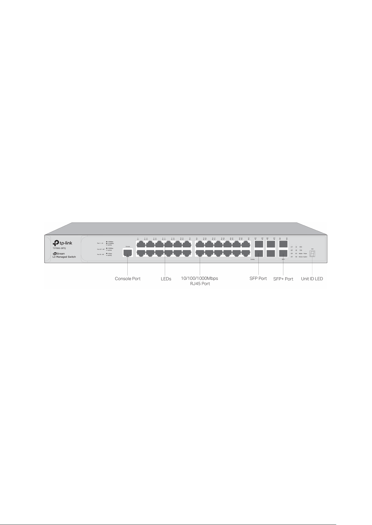
2.2.1 Front Panel
Figure 2-1 Front Panel
The following parts are located on the front panel of the switch:
Console Port: Designed to connect with the serial port of a computer or terminal for
monitoring and configuring the switch.
8
Page 21

LEDs
LED
Status
Indication
On
The switch is powered on
Off
Flashing
Flashing
The switch works properly
On/Off
The switch works improperly
Both the built-in power supply and the redundant power
supply work properly
The built-in power supply works improperly, but the
redundant power supply works properly
The switch is not connected to any redundant power
supply
Green
All the fans work properly
Yellow
Not all the fans work properly
The switch works as master in the stack system, or does
not join any stack system
Off
The switch works as member in the stack system
An Interface Card is connected to the switch and works
properly
An Interface Card is connected to the switch, but works
improperly
Off
No Interface Card is connected to the switch
A 1000Mbps device is connected to the corresponding
Flashing
Data is being transmitted or received
A 10/100Mbps device is connected to the corresponding
Flashing
Data is being transmitted or received
An SFP transceiver is connected to the corresponding
A 1000Mbps device is connected to the corresponding
An SFP transceiver is connected to the corresponding
e, or no SFP
PWR
System
RPS
FAN
Master
The switch is powered off or power supply is abnormal
Power supply is abnormal
Green
On
Yellow
Off
On
Module
Link/Act
(Port 1-24)
21F-24F
On(green)
Flashing(yellow)
On
Green
On
Yellow
On
Flashing
port, but no activity
port, but no activity
port, and it is connected to a device, but no activity
port and transmitting data
Off
port, but it is not connected to a devic
transceiver is connected
9
Page 22

LED
Status
Indication
On
An SFP+ transceiver/cable is connected to the
corresponding port, and it is connected to a 10Gbps
A 10Gbps device is connected to the corresponding port
and transmitting data
An SFP+ transceiver/cable is connected to the
An SFP+ transceiver/cable is connected to the
it is
connected to a 10Gbps device, but no activity
A 10Gbps device is connected to the corresponding port
An SFP+ transceiver/cable is connected to the
but it is not
device, but no activity
25, 26
Flashing
Off
corresponding port, but it is not connected to a device, or
no SFP+ transceiver/cable is connected
On
Flashing
corresponding port of the Interface Card, and
of the Interface Card and transferring data
M1, M2
corresponding port of the Interface Card,
Off
connected to a device, or no SFP+ transceiver/cable is
connected to the Interface Card, or no Interface Card is
connected
10/100/1000Mbps RJ45 Ports: Port 1-24, designed to connect to a device with the
bandwidth of 10Mbps, 100Mbps or 1000Mbps. Each has a corresponding
10/100/1000Mbps LED.
SFP Ports: Port 21F-24F, designed to install the SFP transceiver. These four SFP
transceiver slots are shared with the associated RJ45 ports. The associated two ports are
referred as a “Combo” port, which means they cannot be used simultaneously, otherwise
only RJ45 port works.
SFP+ Ports: Port 25-26, designed to install the 10Gbps SFP+ transceiver/cable.
T3700G-28TQ also provides an interface card slot on the rear panel to install the expansion
card (TX432 of TP-Link for example). If TX432 is installed, you get another two 10Gbps SFP+
ports.
Unit ID LED: Designed to display the stack unit number of the switch. For the switch that
does not join any stack system, it displays its default unit number. To modify the default unit
number, please logon to the GUI of the switch and go to Stack→Stack
Management→Switch Renumber page.
10
Page 23
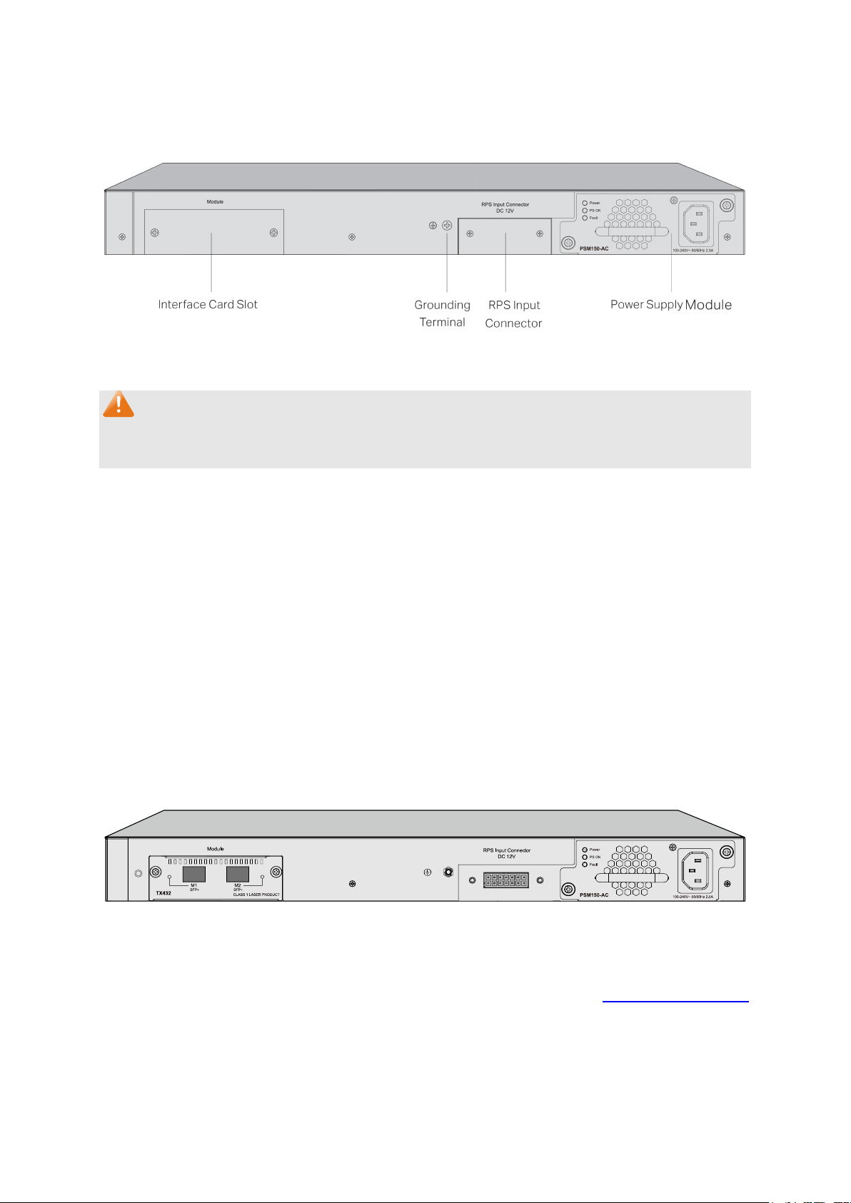
2.2.2 Rear Panel
The rear panel of T3700G-28TQ is shown as the following figure.
Figure 2-2 Rear Panel (1)
Note:
The Interface Card Slot, RPS Input Connector and AC Power Supply Module Slot are shipped
with protective covers.
Interface Card Slot: Designed to extend the interfaces. You can select an Interface Card
(TX432 of TP-Link for example) for your switch if needed.
Grounding Terminal: T3700G-28TQ already comes with Lightning Protection Mechanism.
You can also ground the switch through the PE (Protecting Earth) cable of AC cord or with
Ground Cable. For detailed information, please refer to Installation Guide.
RPS Input Connector: Provides an interface to connect the RPS (Redundant Power Supply).
You can select an RPS (RPS150 of TP-Link for example) for your switch if needed.
Power Supply Module Slot: Provides an interface to install the Power Supply Module. An
AC Power Supply Module PSM150-AC is provided with the switch.
With all the protective covers removed, and the Interface Card (TX432) & Power Supply Module
(PSM150-AC) inserted, the rear panel of T3700G-28TQ is shown as the following figure.
Figure 2-3 Rear Panel (2)
Return to CONTENTS
11
Page 24
Chapter 3 Login to the Switch
3.1 Login
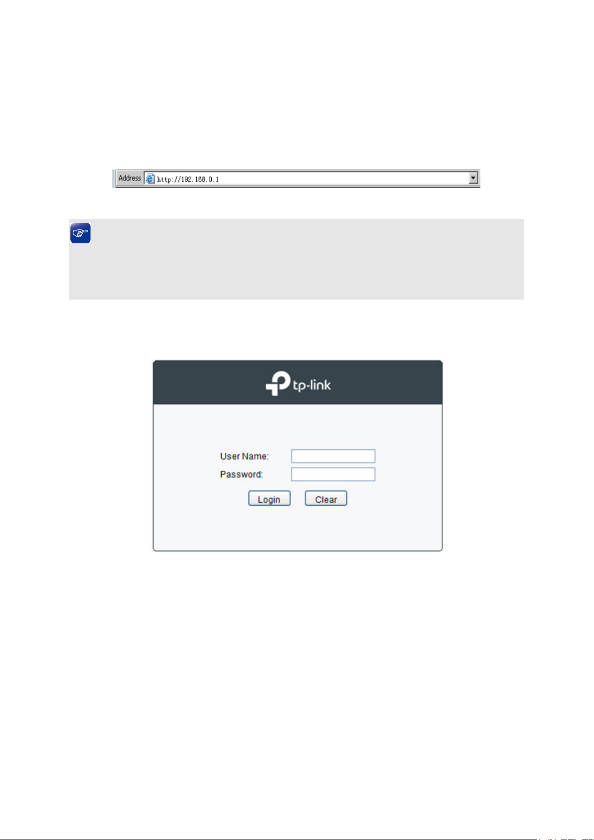
1) To access the configuration utility, open a web-browser and type in the default address
http://192.168.0.1 in the address field of the browser, then press the Enter key.
Figure 3-1 Web-browser
Tips:
To log in to the switch, the IP address of your PC should be set in the same subnet addresses
of the switch. The IP address is 192.168.0.x ("x" is any number from 2 to 254), Subnet Mask is
255.255.255.0.
2) After a moment, a login window will appear, as shown in Figure 3-2. Enter admin for the User
Name and Password, both in lower case letters. Then click the Login button or press the
Enter key.
Figure 3-2 Login
3.2 Configuration
After a successful login, the main page will appear as Figure 3-3, and you can configure the
function by clicking the setup menu on the left side of the screen.
12
Page 25
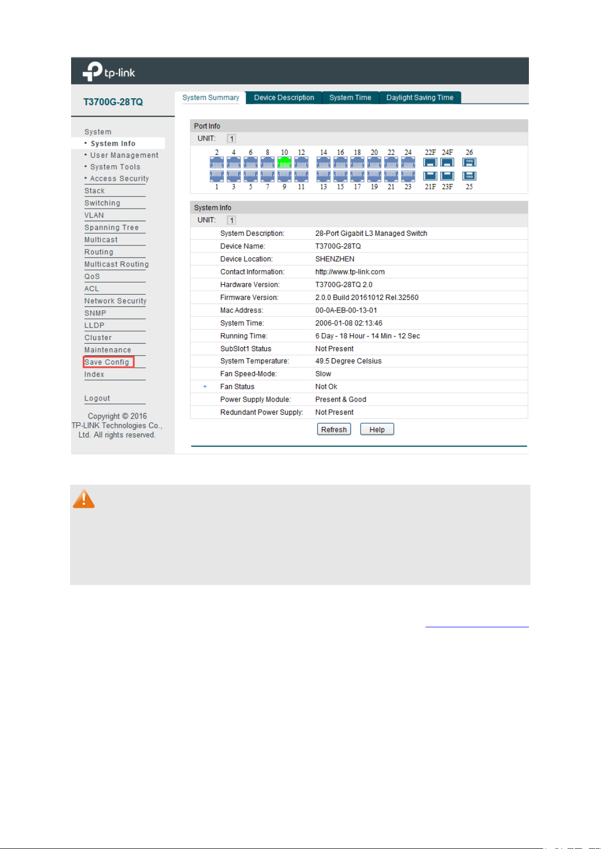
Figure 3-3 Main Setup-Menu
Note:
Clicking Apply can only make the new configurations effective before the switch is rebooted. If
you want to keep the configurations effective even the switch is rebooted, please click Save
Config. You are suggested to click Save Config before cutting off the power or rebooting the
switch to avoid losing the new configurations.
Return to CONTENTS
13
Page 26
Chapter 4 System
The System module is mainly for system configuration of the switch, including four submenus:
System Info, User Management, System Tools and Access Security.
4.1 System Info
The System Info, mainly for basic properties configuration, can be implemented on System
Summary, Device Description, System Time and Daylight Saving Time pages.
4.1.1 System Summary
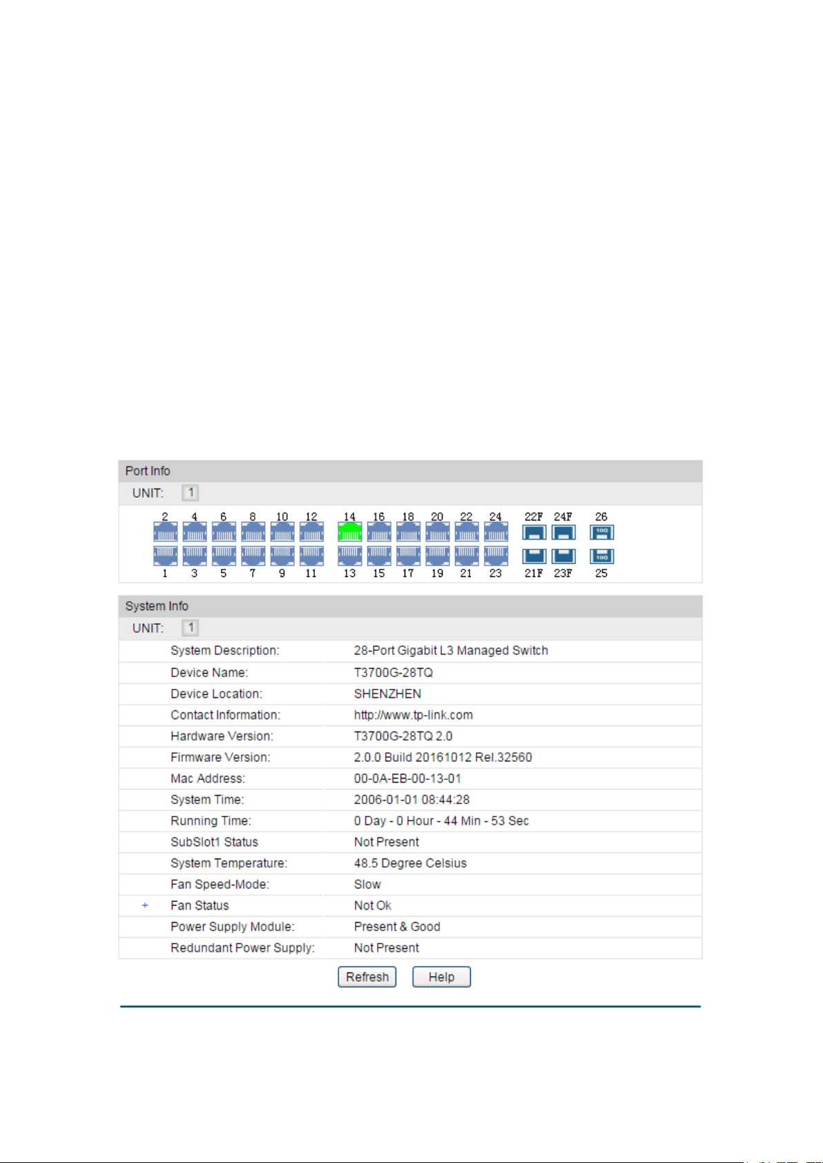
On this page you can view the port connection status and the system information.
The port status diagram shows the working status of 24 10/100/1000Mbps RJ45 ports, 4
1000Mbps SFP ports and 2 10000Mbps SFP ports of the switch. Ports 27T and 28T are Combo
ports with SFP ports labeled 27F and 28F.
Choose the menu System → System Info → System Summary to load the following page.
Figure 4-1 System Summary
14
Page 27
Select the unit ID of the desired member in the stack.
Indicates the 1000Mbps port is at the speed of 1000Mbps.
Indicates the SFP port is not connected to a device.
Indicates the SFP+ port is not connected to a device.
Indicates the SFP+ port is at the speed of 1000Mbps.
Port:
Displays the port number of the switch.
Type:
Displays the type of the port.
Rate:
Displays the maximum transmission rate of the port.
Status:
Displays the connection status of the port.
Port Status
UNIT:
Indicates the 1000Mbps port is not connected to a device.
Indicates the 1000Mbps port is at the speed of 10Mbps or 100Mbps.
Indicates the SFP port is at the speed of 1000Mbps.
Indicates the SFP+ port is at the speed of 10000Mbps.
When the cursor moves on the port, the detailed information of the port will be displayed.
Figure 4-2 Port Information
Port Info
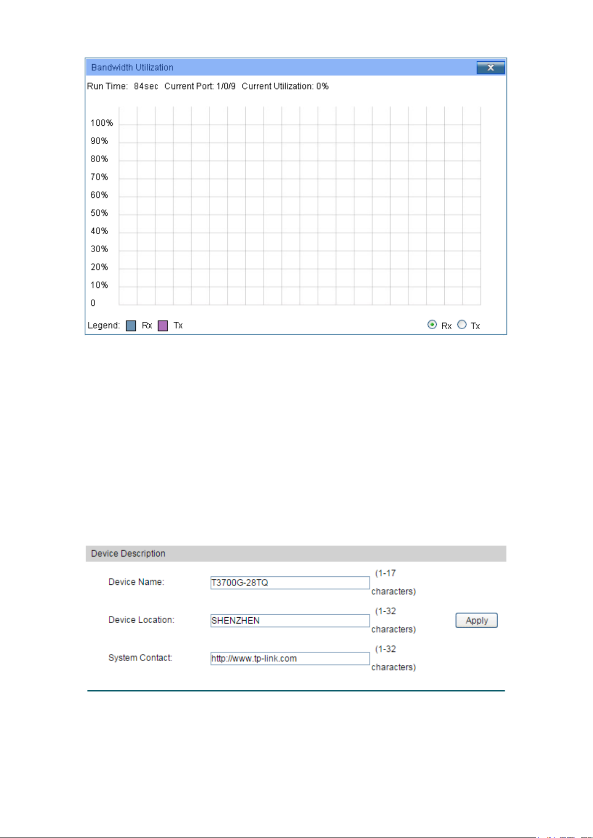
Click a port to display the bandwidth utilization on this port. The actual rate divided by
theoretical maximum rate is the bandwidth utilization.
Figure 4-3 displays the bandwidth
utilization monitored every four seconds. Monitoring the bandwidth utilization on each port
facilitates you to monitor the network traffic and analyze the network abnormities.
15
Page 28
Select Rx to display the bandwidth utilization of receiving
packets on this port.
Select Tx to display the bandwidth utilization of sending packets
on this port.
Figure 4-3 Bandwidth Utilization
Bandwidth Utilization
Rx:
Tx:
4.1.2 Device Description
On this page you can configure the description of the switch, including device name, device
location and system contact.
Choose the menu System → System Info → Device Description to load the following page.
Figure 4-4 Device Description
The following entries are displayed on this screen:
16
Page 29
Device Name:
Enter the name of the switch.
Device Location:
Enter the location of the switch.
System Contact:
Enter your contact information.
Current System Time:
Displays the current date and time of the switch.
Current Time Source:
Displays the current time source of the switch.
When this option is selected, you can set the date and time
manually.
Device Description
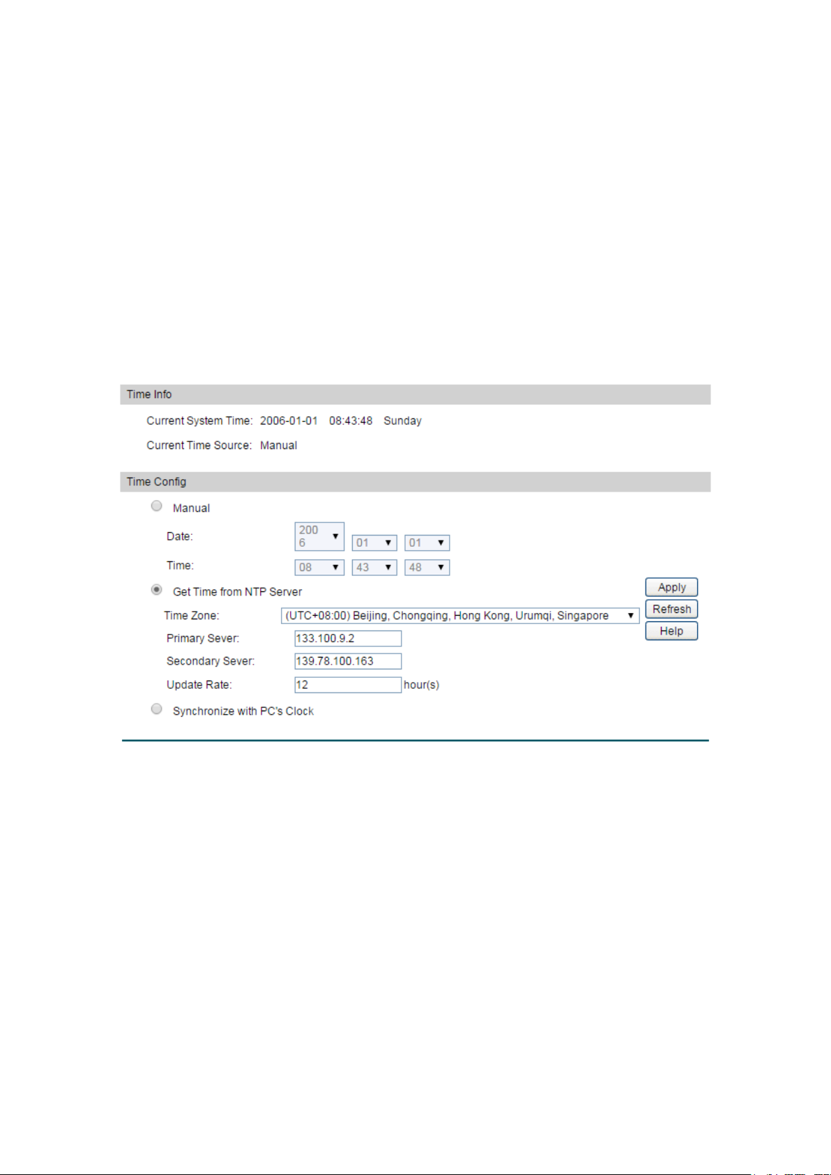
4.1.3 System Time
System Time is the time displayed while the switch is running. On this page you can configure the
system time and the settings here will be used for other time-based functions like ACL.
You can manually set the system time, get UTC automatically if it has connected to an NTP
server or synchronize with PC’s clock as the system time.
Choose the menu System → System Info → System Time to load the following page.
Figure 4-5 System Time
The following entries are displayed on this screen:
Time Info
Time Config
Manual:
17
Page 30
Get Time from NTP
Server:
When this option is selected, you can configure the time zone
and the IP Address for the NTP Server. The switch will get
ddress for
Specify the rate fetching time from NTP
server.
clock is
utilized.
DST Status:
Enable or Disable DST.
UTC automatically if it has connected to an NTP Server.
Time Zone: Select your local time.
Primary/Secondary NTP Server: Enter the IP a
the NTP Server.
Update Rate:
Synchronize with
When this option is selected, the administrator PC’s
PC’S Clock:
Note:
1. The system time will be restored to the default when the switch is restarted and you need to
reconfigure the system time of the switch.
2. When Get Time from NTP Server is selected and no time server is configured, the switch will
get time from the time server of the Internet if it has connected to the Internet.
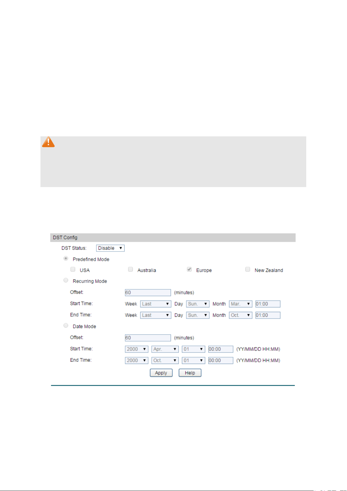
4.1.4 Daylight Saving Time
Here you can configure the Daylight Saving Time of the switch.
Choose the menu System → System Info → Daylight Saving Time to load the following page.
Figure 4-6 Daylight Saving Time
The following entries are displayed on this screen:
DST Config
18
Page 31

USA: Second Sunday in March, 02:00 ~ First Sunday in
lia: First Sunday in October, 02:00 ~ First Sunday
Europe: Last Sunday in March, 01:00 ~ Last Sunday in
New Zealand: Last Sunday in September, 02:00 ~ First
Sunday in April, 03:00.
tion in recurring mode. This
Offset: Specify the time adding in minutes when Daylight
Start/End Time: Select starting time and ending time of
Daylight Saving Time.
ion in Date mode. This
Offset: Specify the time adding in minutes when Daylight
Start/End Time: Select starting time and ending time of
Daylight Saving Time.
Predefined Mode: Select a predefined DST configuration:
November, 02:00.
Austra
in April, 03:00.
October, 01:00.
Recurring Mode: Specify the DST configura
configuration is recurring in use:
Saving Time comes.
Date Mode: Specify the DST configurat
configuration is one-off in use:
Saving Time comes.
Note:
1. When the DST is disabled, the predefined mode, recurring mode and date mode cannot be
configured.
2. When the DST is enabled, the default daylight saving time is of Europe in predefined mode.
4.2 User Management
User Management functions to configure the user name and password for users to log on to
the Web management page with a certain access level so as to protect the settings of the
switch from being randomly changed.
The User Management function can be implemented on User Table and User Config pages.
4.2.1 User Table
On this page you can view the information about the current users of the switch.
Choose the menu System → User Management → User Table to load the following page.
19
Page 32

User Name:
Create a name for users’ login.
Admin can edit, modify and view all the settings of
Guest only can view the settings without the right to
edit and modify.
User Status:
Select Enable/Disable the user configuration.
Password:
Type a password for users’ login.
Confirm Password:
Retype the password.
Figure 4-7 User Table
4.2.2 User Config
On this page you can configure the access level of the user to log on to the Web management
page. The switch provides two access levels: Guest and Admin. The guest only can view the
settings without the right to configure the switch; the admin can configure all the functions of
the switch. The Web management pages contained in this guide are subject to the admin’s login
without any explanation.
Choose the menu System → User Management → User Config to load the following page.
Figure 4-8 User Config
The following entries are displayed on this screen:
User Info
Access Level: Select the access level to login.
Admin:
different functions.
Guest:
20
Page 33

Cipher: Displays the password with ciphertext .
Select the desired entry to delete the corresponding user
optional The current user information
cannot be deleted.
User ID, Name,
Access Level and
status:
Displays the current user ID, user name, access level and user
button of the desired entry, and you can edit the
corresponding user information. After modifying the settings,
button to make the modification
er
information cannot be modified.
Password Display
Mode:
User Table
Select password display mode:
Admin: Displays the password with plaintext in configure file.
Select:
information. It is multi-
status.
Operation: Click the Edit
please click the Modify
effective. Access level and user status of the current us
4.3 System Tools
The System Tools function, allowing you to manage the configuration file of the switch, can be
implemented on Boot Config, Config Restore, Config Backup, Firmware Upgrade, System
Reboot and System Reset pages.
4.3.1 Boot Config
On this page you can configure the boot file and the configuration file of the switch. When the
switch is powered on, it will start up with the startup image. If the startup fails, the switch will try
to start up with the backup image. If this startup fails too, the switch will changes to bootutil
state, in which circumstance the switch’s Web interface is unavailable and you can enter into
the bootutil menu of the switch through the console connection.
When the startup process is finished, the switch will read the startup-config file. If it fails, the
switch will try to read the backup-config file. If it fails too, the switch will be restored to factory
settings.
Choose the menu System → System Tools → Boot Config to load the following page.
21
Page 34

Select:
Select the unit(s).
Unit:
Displays the unit ID.
nt Startup
Image:
Next Startup Image:
Select the next startup image.
Backup Image:
Select the backup boot image.
Current Startup
Config:
Next Startup
Config:
Backup Config:
Input the backup config filename.
Restore:
Set the boot parameter to default.
Figure 4-9 Boot Config
The following entries are displayed on this screen:
Boot Table
Curre
Displays the current startup image.
Displays the current startup config filename.
Input the next startup config filename.
4.3.2 Config Restore
On this page you can upload a backup configuration file to restore your switch to this previous
configuration.
Choose the menu System → System Tools → Config Restore to load the following page.
22
Page 35

it in the stack to restore it to a backup
configuration.
It will take effect after the switch automatically reboots.
Select the desired unit in the stack to backup its configuration
file.
Figure 4-10 Config Restore
The following entries are displayed on this screen:
Config Restore
Target Unit: Select the desired un
Import: Click the Import button to restore the backup configuration file.
Note:
1. It will take a few minutes to restore the configuration. Please wait without any operation.
2. To avoid any damage, please don’t power down the switch while being restored.
3. After being restored, the current settings of the switch will be lost. Wrong uploaded
configuration file may cause the switch unmanaged.
4.3.3 Config Backup
On this page you can download the current configuration of the specified unit in the stack and
save it as a file to your computer for your future configuration restore.
Choose the menu System → System Tools → Config Backup to load the following page.
Figure 4-11 Config Backup
The following entries are displayed on this screen:
Config Backup
Target Unit:
23
Page 36

button to save the current configuration as a
file to your computer. You are suggested to take this measure
before upgrading.
Export: Click the Export
Note:
It will take a few minutes to backup the configuration. Please wait without any operation.
4.3.4 Firmware Upgrade
The switch system can be upgraded via the Web management page. To upgrade the system is
to get more functions and better performance. Go to http://www.tp-link.com
updated firmware.
Choose the menu System→System Tools→Firmware Upgrade to load the following page.
to download the
Figure 4-12 Firmware Upgrade
Note:
1. Don’t interrupt the upgrade.
2. Please select the proper software version matching with your hardware to upgrade.
3. To avoid damage, please don't turn off the device while upgrading.
4. After upgrading, the device will reboot automatically.
5. You are suggested to backup the configuration before upgrading.
4.3.5 System Reboot
On this page you can reboot the specified unit switch in the stack and return to the login page.
Please save the current configuration before rebooting to avoid losing the configuration
unsaved
Choose the menu System→System Tools→System Reboot to load the following page.
Figure 4-13 System Reboot
24
Page 37

Note:
To avoid damage, please don't turn off the device while rebooting.
4.3.6 System Reset
On this page you can reset the specified unit in the stack to the default. All the settings will be
cleared after the switch is reset.
Choose the menu System→System Tools→System Reset to load the following page.
Figure 4-14 System Reset
Note:
After the system is reset, the switch will be reset to the default and all the settings will be
cleared.
4.4 Access Security
Access Security provides different security measures for the remote login so as to enhance
the configuration management security. It can be implemented on Access Control, SSL Config
and SSH Config pages.
4.4.1 Access Control
On this page you can control the users logging on to the Web management page to enhance
the configuration management security. The definitions of Admin and Guest refer to
Management. This function only applies to Web, SNMP, Telnet, SSL and SSH.
Choose the menu System→Access Security→Access Control to load the following page.
4.2 User
25
Page 38

Select the control mode for users to log on to the Web
range of the users
Select this option to limit the MAC Address of
Port-based: Select this option to limit the ports for login.
These fields can be available for configuration only when
range
you set here are allowed for login.
The field can be available for configuration only when
Only the user with this MAC
Address you set here is allowed for login.
The field can be available for configuration only when
based mode is selected. Only the users connected to
these ports you set here are allowed for login.
If you do nothing with the Web management page within the
timeout time, the system will log out automatically. If you want
to reconfigure, please login again.
Figure 4-15 Access Control
The following entries are displayed on this screen:
Access Control Config
Control Mode:
management page.
IP-based: Select this option to limit the IP-
for login.
MAC-based:
the users for login.
IP Address& Mask:
IP-based mode is selected. Only the users within the IP-
MAC Address:
MAC-based mode is selected.
Port:
Port-
Session Config
Session Timeout:
26
Page 39

Number Control:
Select Enable/Disable the Number Control function.
Enter the maximum number of the users logging on to the Web
management page as Admin.
Enter the maximum number of the users logging on to the Web
management page as Guest.
Access User Number
Admin Number:
Guest Number:
4.4.2 SSL Config
SSL (Secure Sockets Layer), a security protocol, is to provide a secure connection for the
application layer protocol (e.g. HTTP) communication based on TCP. SSL is widely used to
secure the data transmission between the Web browser and servers. It is mainly applied
through ecommerce and online banking.
SSL mainly provides the following services:
1. Authenticate the users and the servers based on the certificates to ensure the data are
transmitted to the correct users and servers;
2. Encrypt the data transmission to prevent the data being intercepted;
3. Maintain the integrality of the data to prevent the data being altered in the transmission.
Adopting asymmetrical encryption technology, SSL uses key pair to encrypt/decrypt
information. A key pair refers to a public key (contained in the certificate) and its corresponding
private key. By default the switch has a certificate (self-signed certificate) and a corresponding
private key. The Certificate/Key Download function enables the user to replace the default key
pair.
After SSL is effective, you can log on to the Web management page via https://192.168.0.1
. For
the first time you use HTTPS connection to log into the switch with the default certificate, you
will be prompted that “The security certificate presented by this website was not issued by a
trusted certificate authority” or “Certificate Errors”. Please add this certificate to trusted
certificates or continue to this website.
On this page you can configure the SSL function.
27
Page 40

SSL:
Select Enable/Disable the SSL function on the switch.
Select the desired certificate to download to the switch. The
certificate must be BASE64 encoded.
Select the desired SSL Key to download to the switch. The key
must be BASE64 encoded.
Choose the menu System→Access Security→SSL Config to load the following page.
Figure 4-16 SSL Config
The following entries are displayed on this screen:
Global Config
Certificate Download
Certificate File:
Key Download
Key File:
Note:
1. The SSL certificate and key downloaded must match each other; otherwise the HTTPS
connection will not work.
2. The SSL certificate and key downloaded will not take effect until the switch is rebooted.
3. To establish a secured connection using https, please enter https:// into the URL field of
the browser.
4. It may take more time for https connection than that for http connection, because https
connection involves authentication, encryption and decryption etc.
4.4.3 SSH Config
As stipulated by IFTF (Internet Engineering Task Force), SSH (Secure Shell) is a security
protocol established on application and transport layers. SSH-encrypted-connection is similar
to a telnet connection, but essentially the old telnet remote management method is not safe,
because the password and data transmitted with plain-text can be easily intercepted. SSH can
provide information security and powerful authentication when you log on to the switch
remotely through an insecure network environment. It can encrypt all the transmission data and
prevent the information in a remote management being leaked.
28
Page 41

SSH:
Select Enable/Disable SSH function.
Protocol V1:
Select Enable/Disable SSH V1 to be the supported protocol.
Protocol V2:
Select Enable/Disable SSH V2 to be the supported protocol.
Specify the idle timeout time. The system will automatically
t time is
120 seconds.
Specify the maximum number of the connections to the SSH
server. No new connection will be established when the number
of the connections reaches the maximum number you set. The
default value is 5.
Select the type of SSH Key to download. The switch supports
three types: SSH-1 RSA, SSH-2 RSA and SSH-2 DSA.
Comprising server and client, SSH has two versions, V1 and V2 which are not compatible with
each other. In the communication, SSH server and client can auto-negotiate the SSH version
and the encryption algorithm. After getting a successful negotiation, the client sends
authentication request to the server for login, and then the two can communicate with each
other after successful authentication. This switch supports SSH server and you can log on to
the switch via SSH connection using SSH client software.
SSH key can be downloaded into the switch. If the key is successfully downloaded, the
certificate authentication will be preferred for SSH access to the switch.
Choose the menu System→Access Security→SSH Config to load the following page.
Figure 4-17 SSH Config
The following entries are displayed on this screen:
Global Config
Idle Timeout:
release the connection when the time is up. The defaul
Max Connect:
Key Download
Key Type:
29
Page 42

Key File:
Select the desired key file to download.
button to down the desired key file to the
switch.
Download: Click the Download
Note:
1. Please ensure the key length of the downloaded file is in the range of 256 to 3072 bits.
2. After the Key File is downloaded, the user’s original key of the same type will be replaced.
The wrong uploaded file will result in the SSH access to the switch via Password
authentication.
Application Example 1 for SSH:
Network Requirements
1. Log on to the switch via password authentication using SSH and the SSH function is
enabled on the switch.
2. PuTTY client software is recommended.
Configuration Procedure
1. Open the software to log on to the interface of PuTTY. Enter the IP address of the switch
into Host Name field; keep the default value 22 in the Port field; select SSH as the
Connection type.
30
Page 43

2. Click the Open button in the above figure to log on to the switch. Enter the login user name
and password, and then you can continue to configure the switch.
Application Example 2 for SSH:
Network Requirements
1. Log on to the switch via key authentication using SSH and the SSH function is enabled on
the switch.
2. PuTTY client software is recommended.
Configuration Procedure
1. Select the key type and key length, and generate SSH key.
Note:
1. The key length is in the range of 256 to 3072 bits.
2. During the key generation, randomly moving the mouse quickly can accelerate the key
generation.
31
Page 44

2. After the key is successfully generated, please save the public key and private key to the
computer.
3. On the Web management page of the switch, download the public key file saved in the
computer to the switch.
Note:
1. The key type should accord with the type of the key file.
2. The SSH key downloading cannot be interrupted.
32
Page 45

4. After the public key is downloaded, please log on to the interface of PuTTY and enter the IP
address for login.
5. Click Browse to download the private key file to SSH client software and click Open.
33
Page 46

After successful authentication, please enter the login user name. If you log on to the switch
without entering password, it indicates that the key has been successfully downloaded.
Note:
Following the steps above, you have already entered the User EXEC Mode of the switch.
However, to configure the switch, you need a password to enter the Privileged EXEC Mode first.
For a switch with factory settings, the Privileged EXEC Mode password can only be configured
through the console connection. For how to configure the Privileged EXEC Mode password,
please refer to the 1.1.2 Configuring the Privileged EXEC Mode Password in CLI Reference
Guide.
Return to CONTENTS
34
Page 47

Chapter 5 Stack
The stack technology is to connect multiple stackable devices through their StackWise ports,
forming a stack which works as a unified system and presents as a single entity to the network
in Layer 2 and Layer 3 protocols. It enables multiple devices to collaborate and be managed as
a whole, which improves the performance and simplifies the management of the devices
efficiently.
Advantages
The stack delivers the following benefits:
1. Simplified management. After stack establishment, the user can log in the stack system
through any StackWise ports of stackable devices, and manage it as a single device. You
only need to configure the stack system once instead of operating repetitive configuration
on multiple devices. Various ways such as CONSOLE, SNMP, TELNET and WEB are
available for users to manage the stack.
2. High reliability. The stack is highly reliable in following aspects:
1) The stack system is comprised of multiple devices among which one member device
works as the stack master to take charge of the operation, management and
maintenance of the stack, while the other stack members process services and keep a
copy configuration file in accordance with the master for providing backup
simultaneously. Once the stack master becomes unavailable, the remaining stack
members elect a new master among themselves instantly and automatically, which can
ensure uninterrupted services and furthermore making 1:N backup feasible. Due to the
real-time configuration and data synchronization being strictly executed, the new
master can take over the previous master to manage and maintain the stack system
smoothly without affecting its normal operation.
2) Distributed LACP (Link Aggregation Control Protocol) supports link aggregation across
devices. Since the whole stack system presents as a single device on the network,
external devices can implement LACP with the stack system by connecting to several
stack member devices simultaneously. Among the links between the stack system and
external devices, load distribution and backup can be realized to increase the reliability
of the stack system and to simplify dramatically the network topology as Figure 5-1
shows.
35
Page 48

Figure 5-1 Distributed LACP
In a ring connected stack, it can still operate normally by transforming into a daisy
chained stack when link failure occurs, which further ensures the normal operation of
load distribution and backup across devices and links as Figure 5-2 shows.
Figure 5-2 Load Distribution and Backup across Devices
3. Network scalability. Each member device in the stack system is able to process protocol
packets and forward data individually, which enables you to increase the port number and
bandwidth of the stack system by adding new member devices. The users are free to add
or remove stack members without affecting the normal running of the stack, which enables
them to protect the existed resources furthest during network upgrades.
36
Page 49

Application Diagram
Figure 5-3 Application Diagram
Stack Introduction
1. Stack Elements
1) Stack Role
Each device in the stack system is called stack member. Each stack member processes
services packets and plays a role which is either master or member in the stack system.
The differences between master and member are described as below:
• Master: Indicates the device is responsible for managing the entire stack system.
• Member: Indicates the device provides backup for the master. If the master fails, the
stack will elect a new master from the remaining members to succeed the previous
master.
2) Stack Event
Stack event indicates the global events which might happen during stack operation
process, with two options:
• Merge: It occurs when two independent stacks merge into one stack because of stack
link establishment, as shown in the following figure:
Figure 5-4 Stack Merge
37
Page 50

When stack merge occurs, the previous masters compete to be the new master. The
stack members of the defeated stack will join the winner stack as a member to form a
new stack. Master will assign Unit Number to the newly joined members and compare
their configuration files. The members with different configurations files with the master
will download the configuration files of the master and re-configure.
• Split: It occurs when stack splits into two or more stacks because of stack link failures,
as shown in the following figure:
Figure 5-5 Stack Split
After stack partition occurs, each newly established stack elects their own new master
and use the MAC address of the master as its stack MAC address. However, stack
partition probably brings about routing and forwarding problems on the network since
the partitioned stacks keep operating with the previous IP address by default, which
results in same IP address being reused in the same LAN.
2. Operation Procedure
Stack management involves these four stages: Connecting the stack members, Topology
collection, Master election, and Stack management and maintenance.
1) Connecting the stack members
To establish a stack, please physically connect the stack ports of the member devices with
cables. The stack ports of T3700-28TQ can be used for stack connection or as normal
Ethernet Gigabit port. When you want to establish a stack, the stack mode of the related
ports should be configured as "Enable". If the stack mode of the port is "Disable", then the
port will work as a normal Ethernet port.
Stack typically adopts a daisy chain topology or ring topology as shown in Figure 5-6:
Figure 5-6 Stack Connect Topology
38
Page 51

• The daisy chain topology is mainly used in a network where member devices are
distributively located.
• The ring topology is more reliable than the daisy chain topology. In a daisy chained
stack, link failure can cause stack split. While in a ring connected stack, the system is
able to operate normally with a new daisy chained topology.
Note:
Establish a stack of ring or daisy chain topology with eight T3700-28TQ switches at most.
2) Topology Collection
Each member in the stack collects the topology of the whole stack by exchanging stack
discovery packets with its neighbors. Discovery packet carries topology information
including stack port connection status, unit number, priorities, MAC addresses, etc.
Each member keeps a local record of the known topology information. When the device
initializes, it only possesses the record of its own topology information. Periodically the
stack members send out their known topology information through the stack ports to its
neighbors. When the neighbors receive the information, they will update their local
topology information. After a period of time of broadcasting and updating information, all
the stack members can collect the complete topology information (known as topology
convergence).
Then the switch enters the master election stage.
3) Master Election
After all members have obtained topology information (known as topology convergence),
the stack enters the master election stage. A stack always has one stack master, while the
other stack members are members. Master election determines the stack role of the stack
members.
Master election is held each time the topology changes, for example, when stack merge or
split occurs, or the stack or the current master is reset.
The master is elected based on the following rules and in the order listed:
1. The switch that is currently the stack master.
2. The switch with the highest stack member priority value.
3. The switch with the lowest MAC address.
After master election, the stack forms and enters into stack management and
maintenance stage.
Note:
1. The priority value ranges from 1 to 15. The higher the value is, the more likely the
member will be elected as the master. By default, the member priority of the switch is 5.
We recommend you manually assign the highest priority value to the switch that you
prefer to be the stack master before stack establishment.
2. The switch is non-preemptible when it joins the stack in cold-start mode, and the
process is illustrated as bellow: the switch has no stack role at its start, and it sends out
39
Page 52

discovery messages to collect the topology of the current stack system. After the
topology collection, the switch obtains its role according to the rules above. The switch
will become stack member if there is already a master in the stack. The master will
resume its role even if the newly joined switch has a higher priority.
4) Stack Management and Maintenance
After the stack is established, all the stack members are integrated into a virtual device in
the network and managed by the master. The following section briefly introduces the
concepts and rules involved in stack management stage.
• Unit Number: When the stack is running, unit number is used to identify and manage
member devices. Unit number is unique in a stack system. The factory default unit
number of switch is 1. In order to keep its uniqueness, before establishing stack you are
kindly recommended to prepare a unit number assignment scheme and then manually
configure it on each member device.
During unit number assignment process, the master prioritizes the member devices
already carrying manually assigned unit number. If the unit number has not been used
by other stack members the member device will keep it. Otherwise, the unit number is
configured based on the following rules and in the order listed:
1. The device which was managed by the current master before the configuration will
resume its unit number.
2. The device with manually assigned unit number is prior to the device whose unit
number assignment mode is “Auto”.
3. The device with the highest stack member priority value.
4. The device with the lowest MAC address.
Note:
1. You can get the current unit number of the switch from the unit number LED on the
front panel of the switch.
2. When the stack is running, if you want to change the unit number manually, only the
unit numbers which have not been occupied by the other member devices are
available for you to choose from.
• Port Number Format:
The format of port number should be Unit Number/Slot Number/Port Number. Among
them:
(1) Unit Number: The default unit number of the switch is 1. If a device has joined
stack system, the unit number which the device possesses in the stack system
will be kept using as its unit number after the device leaves the stack system.
(2) Slot Number: Indicates the number of the slot the interface card is in. For
T3700G-28TQ, the front panel ports belong to slot 0. Slot number starting from 1
each represents an interface card slot.
(3) Physical Port Number: The physical port number on the switch which can be
obtained through the front panel of the switch.
40
Page 53

For instance: Port number 2/0/3 indicates the physical port3 on the switch whose unit
number is 2.
• Configuration Files Application Rules: It includes global configuration and interface
configuration two parts.
(1) The global configurations of all stack members are the same. Besides, each
member device keeps pace with the global configuration of the master device
which enables the stack system to work just like a single entity in the network. The
stack system adopts the following methods to ensure the synchronization of
global configuration files:
When the stack initializes, the master device will compare the configuration files
of each stack member and reconfigure the device whose global configuration is
different from its own, so as to ensure the global configuration of the stack
members are exactly the same.
When the stack is work normally, any global configuration of users will be
recorded to the current configuration files of master and then be synchronized to
the other members in the stack.
(2) Each stack member only saves the configuration of its own ports. Even when user
sets the configuration for all ports, the configuration will also be saved and
implemented only on the related stack member which the ports belong to.
• Stack Maintenance
Stack maintenance mainly functions to monitor the join and leave of member devices,
collect the new topology at any times and maintain the current topology.
When the stack is operating normally, packets are transmitted constantly between
stack members. The switch can quickly judge the link status of the stack port via
monitoring the response of the packets. When the switch detects the link status
changes, it will recollect system topology and update topology database to ensure the
normal operation of the stack.
The events that will change the link status of the stack port which thus affecting the
system topology include: stack member failure or leave, new member's coming, link
failure or failure recovery, etc.
When the master switch fails, the stack system elects a new master from the remaining
members to succeed the previous master.
5.1 Stack Management
Before configuring the stack, we highly recommend you to prepare the configuration planning
with a clear set of the role and function of each member device. Some configuration needs
device reboot to take effect, so you are kindly recommended to configure the stack at first,
next connect the devices physically after powering off them, then you can power them on and
the devices will join the stack automatically. After stack is established, users can log in the
stack system through any member devices to configure and manage it.
The stack management can be implemented on Stack Info, Stack Config and Switch
Renumber pages.
41
Page 54

Stack Name:
Displays the name of the stack.
Displays the current MAC address of the stack which usually is
the MAC address of the master switch. The stack uses it to
communicate with other devices.
Displays the current topology type of the stack. There are two
s: Line and Ring. Line represents chain type connection
and Ring indicates ring type connection.
Stack Auth Mode:
Displays the authentication mode used in stack creation.
Switch#:
Displays the unit number of the member switch.
the stack role of the member switch in the stack. There
are two options: Master and Member.
MAC Address:
Displays the MAC address of the member switch.
Displays the member priority of the member switch. The higher
likely the member will be elected as the
master.
Version:
Displays the current firmware version of the member switch.
5.1.1 Stack Info
On this page you can view the basic parameters of the stack function. Choose the menu Stack
Management→Stack Info to load the following page.
Figure 5-7 Stack Info
The following entries are displayed on this screen:
Stack Config
Stack MAC:
Stack Topo:
option
Stack Member Info
Role: Displays
Priority:
the value is, the more
42
Page 55

Status:
Displays the stack status of the member switch.
Stack Port:
Displays the stack port number.
Status:
Displays the stack port status.
Displays the MAC address of the switch which is directly
connecting to the stack port.
Enter the name of the stack. The length of this field should be
ers. After the stack is established, the name of
master determines the stack name.
Stack Port Info:
Neighbor:
5.1.2 Stack Config
On this page you can configure the basic parameters of the stack function.
Choose the menu Stack Management→Stack Config to load the following page.
Figure 5-8 Stack Config
The following entries are displayed on this screen:
Stack Config
Stack Name:
1-30 charact
43
Page 56

Select the authentication mode used in stack creation. There
ted in stack
: Indicates simple plain text authentication mode is
: Indicates MD5 authentication mode is adopted in stack
creation.
n
if the Stack Auth Mode is "Simple" or "MD5".
Retype the authentication password which should be the same
with above.
Switch#:
The unit number of the switch.
Role:
The role of the switch in the stack as Master or Member.
MAC Address:
The unique identification of the switch.
The priority for the stack member. The priority ranges from 1 to
affect the current stack master. The new priority helps
determine which stack member is elected as the new stack
master when the current stack master or the switch stack
resets.
Stack Port:
Select the desired switch port. It is multi-optional.
Allows you to Enable/Disable the stack feature of the specified
port.
Stack Auth Mode:
are three options: "None", "Simple" and "MD5".
• None: Indicates no authentication mode is adop
creation.
• Simple
adopted in stack creation.
• MD5
Stack Auth Key: Enter the authentication password used in stack authenticatio
Input Again:
Stack Priority Config
Priority:
15. The new priority value takes effect immediately but does not
Stack Port Config
Status:
5.1.3 Switch Renumber
In a stack system, unit number is implemented to identify and manage the member device. Unit
number is unique in a stack system. Unit number can be assigned automatically by stack
system or manually configured by users. On this page, you can configure the unit number of
member switch.
Choose the menu Stack Management→Switch Renumber to load the following page.
Figure 5-9 Switch Renumber
44
Page 57

Select:
Select the desired entry. It is multi-optional.
Current Unit:
Displays the current unit number of the member switch.
Auto: With this option selected, the member switch will be
ed, the member switch will be
assigned this unit number if it has not been used by the other
members, otherwise the member switch will be assigned a
Only the unused unit number
is available for you to choose from.
Role:
The role of the device in a stack.
MAC Address:
Displays the MAC address of the member switch.
Step
Operation
Description
port name.
configure the stack name.
Configure stack
Config table.
password.
Configure the
switch priority.
configure the switch priority in the Stack Priority Config table.
number.
Switch Renumber
page, configure the unit number of the switch.
The following entries are displayed on this screen:
Switch Renumber
Designated Unit: Configure the unit number of the member switch.
•
assigned a free unit number automatically.
• 0-7: With this option select
free unit number automatically.
Configuration Procedure:
1 Configure the stack
2
port mode.
3 Configure
authentication
Optional. On Stack→Stack Management→Stack Config page,
Required. On Stack→Stack Management→Stack Config page,
configure the stack port status as “Enable” in the Stack Port
Optional. On Stack→Stack Management→Stack Config page,
select the Stack Auth Mode and configure the Stack Auth Key.
mode and
authentication
4
5 Configure the unit
Optional. On Stack→Stack Management→Stack Config page,
Optional. On Stack→Stack Management→
5.2 Application Example for Stack
Network Requirements
Establish a stack of ring topology with four T3700-28TQ switches.
45
Page 58

Step
Operation
Description
Configure the stack
name.
configure the stack name.
Configure stack port
mode.
configure the stack port status as "Enable".
authentication mode
and authentication
password.
select the Stack Auth Mode and configure the Stack Auth
configure the unit number of switch A, B, C and D as 1, 2, 3
and 4 respectively.
Network Diagram
Configuration Procedure
Configure switch A, B, C and D before physically connecting them:
1
2
3 Configure
Optional. On Stack Management→Stack Config page,
Required. On Stack Management→Stack Config page,
Optional. On Stack Management→Stack Config page,
Key.
4 Configure unit number Optional. On Stack Management→Stack Renumber page,
Connect the switches:
Connect switch A, B, C and D as the network diagram shows, and then power the switches on
to establish a stack.
Return to CONTENTS
46
Page 59

UNIT:
Select the unit ID of the desired member in the stack.
Select:
Select the desired port for configuration. It is multi-optional.
Chapter 6 Switching
Switching module is used to configure the basic functions of the switch, including four
submenus: Port, LAG, Traffic Monitor and MAC Address.
6.1 Port
The Port function, allowing you to configure the basic features for the port, is implemented on
the Port Config, Port Mirror, Port Security, Port Isolation and Loopback Detection pages.
6.1.1 Port Config
On this page, you can configure the basic parameters for the ports. When the port is disabled, the
packets on the port will be discarded. Disabling the port which is vacant for a long time can
reduce the power consumption effectively. And you can enable the port when it is in need.
The parameters will affect the working mode of the port, please set the parameters appropriate
to your needs.
Choose the menu Switching→Port→Port Config to load the following page.
Figure 6-1 Port Config
The following entries are displayed on this screen.
Port Config
47
Page 60

Port:
Type:
Displays the port medium.
Description:
Give a description to the port for identification.
Status: Allows you to Enable/Disable the port. When Enable is
selected, the port can forward the packets normally.
Speed: Select the Speed mode for the port. The device connected to
the switch should be in the same Speed and Duplex mode
with the switch. When 'Auto' is selected, the Speed mode will
be determined by auto negotiation.
Duplex: Select the Duplex mode for the port. When 'Auto' is selected,
the Duplex mode will be determined by auto negotiation.
Flow Control:
Allows you to Enable/Disable the Flow Control feature. When
an synchronize the
speed with its peer to avoid the packet loss caused by
congestion.
LAG:
Displays the LAG number which the port belongs to.
Displays the port number.
Flow Control is enabled, the switch c
Note:
1. The switch cannot be managed through the disabled port. Please enable the port which is
used to manage the switch.
2. The parameters of the port members in a LAG should be set as the same.
6.1.2 Port Mirror
Port Mirror, the packets obtaining technology, functions to forward copies of packets from
one/multiple ports (mirrored port) to a specific port (mirroring port). Usually, the mirroring port
is connected to a data diagnose device, which is used to analyze the mirrored packets for
monitoring and troubleshooting the network.
Choose the menu Switching→Port→Port Mirror to load the following page.
48
Page 61

Session:
This column displays the mirror session number.
Destination:
This column displays the mirroring port.
Mode:
This column displays the mirror mode.
Source:
This column displays the mirrored ports.
Operation:
", or
clear the mirror session configuration by clicking the "Clear".
Figure 6-2 Mirror Session List
The following entries are displayed on this screen.
Mirror Session List
You can configure the mirror session by clicking the "Edit
Click Edit button to modify the settings of the corresponding session in the following page.
Click Clear button to clear the configuration of the corresponding session.
49
Page 62

Session:
Displays session number.
Destination Port:
Input or select a physical port from the port panel as the
mirroring port.
Select:
Select the desired port as a mirrored port. It is multi-optional.
Figure 6-3 Port Mirror Config
The following entries are displayed on this screen.
Mirror Session
Destination Port
Source Port
50
Page 63

Port:
Displays the port number.
Ingress:
Select Enable/Disable the Ingress feature. When the Ingress is
enabled, the incoming packets received by the mirrored port will
be copied to the mirroring port.
Egress:
Select Enable/Disable the Egress feature. When the Egress is
enabled, the outgoing packets sent by the mirrored port will be
copied to the mirroring port.
LAG: Displays the LAG number which the port belongs to. The LAG
cannot be selected as the mirrored port or mirroring
port.
member
Note:
1. The LAG member cannot be selected as the mirroring port.
2. A port cannot be set as the mirrored port and the mirroring port simultaneously.
3. The Port Mirror function can span the multiple VLANs.
6.1.3 Port Security
MAC Address Table maintains the mapping relationship between the port and the MAC
address of the connected device, which is the base of the packet forwarding. The capacity of
MAC Address Table is fixed. MAC Address Attack is the attack method that the attacker takes
to obtain the network information illegally. The attacker uses tools to generate the cheating
MAC address and quickly occupy the MAC Address Table. When the MAC Address Table is full,
the switch will broadcast the packets to all the ports. At this moment, the attacker can obtain
the network information via various sniffers and attacks. When the MAC Address Table is full,
the packets traffic will flood to all the ports, which results in overload, lower speed, packets
drop and even breakdown of the system.
Port Security is to protect the switch from the malicious MAC Address Attack by limiting the
maximum number of MAC addresses that can be learned on the port. The port with Port
Security feature enabled will learn the MAC address dynamically. When the learned MAC
address number reaches the maximum, the port will stop learning. Thereafter, the other
devices with the MAC address unlearned cannot access to the network via this port.
51
Page 64

UNIT:
Select the unit ID of the desired member in the stack.
Select:
multi-optional.
Port:
Max Learned MAC:
learned on the port.
Learned Num:
Displays the number of MAC addresses that have been
learned on the port.
Learn Mode:
Permanent: When Permanent mode is selected, the
Choose the menu Switching→Port→Port Security to load the following page.
Figure 6-4 Port Security
The following entries are displayed on this screen:
Port Security
Select the desired port for Port Security configuration. It is
Displays the port number.
Specify the maximum number of MAC addresses that can be
Select the Learn Mode for the port.
• Dynamic: When Dynamic mode is selected, the learned
MAC address will be deleted automatically after the aging
time.
• Static: When Static mode is selected, the learned MAC
address will be out of the influence of the aging time and
can only be deleted manually. The learned entries will be
cleared after the switch is rebooted.
•
52
Page 65

learned MAC address will be out of the influence of the
entries will be saved even the switch is rebooted.
Status:
Select Enable/Disable the Port Security feature for the port.
UNIT:
Select the unit ID of the desired member in the stack.
Port:
Display the port number.
Forward Portlist:
Display the forward list.
aging time and can only be deleted manually. The learned
Note:
1. The Port Security function is disabled for the LAG port member. Only the port is removed
from the LAG, will the Port Security function be available for the port.
2. The Port Security function is disabled when the 802.1X function is enabled.
6.1.4 Port Isolation
Port Isolation provides a method of restricting traffic flow to improve the network security by
forbidding the port to forward packets to the ports that are not on its forward portlist.
Choose the menu Switching→Port→Port Isolation to load the following page.
Figure 6-5 Port Isolation Config
The following entries are displayed on this screen:
Port Isolation List
53
Page 66

UNIT:
Select the unit ID of the desired member in the stack.
Port:
Select the port number to set its forward list. It is multi-optional.
Forward Portlist:
Select the port that to be forwarded to. It is multi-optional.
Click the Edit button to configure the port isolation list in the following page:
Figure 6-6 Port Isolation Config
Port Isolation Config
Click the Back button to go back to the port isolation list.
6.1.5 Loopback Detection
With loopback detection feature enabled, the switch can detect loops using loopback
detection packets. When a loop is detected, the switch will display an alert or further block the
corresponding port according to the port configuration.
54
Page 67

Status:
r disable Loopback Detection function
globally.
Set a Loopback Detection interval between 1 and 1000
seconds. By default, it’s 30 seconds.
Time after which the blocked port would automatically recover
. It can be set as integral times of detection
interval.
Web Refresh
Status:
Interval:
Set a web refresh interval between 3 and 100 seconds. By
default, it is 6 seconds.
Choose the menu Switching → Port → Loopback Detection to load the following page.
Figure 6-7 Loopback Detection Config
The following entries are displayed on this screen:
Global Config
LoopbackDetection
Here you can enable o
Detection Interval:
Automatic
Recovery Time:
to normal status
Here you can enable or disable web automatic refresh.
Web Refresh
55
Page 68

Select the desired port for Loopback Detection configuration. It
is multi-optional.
Port:
Displays the port number.
Status:
Enable or disable Loopback Detection function for the port.
When a loop is detected, display an alert and
block the port.
the mode how the blocked port recovers to normal
ically removed after
Manual: Block status only can be removed manually.
Loop Status:
Displays the port status whether a loopback is detected.
Block Status:
Displays the port status about block or unblock.
LAG:
Displays the LAG number the port belongs to.
Recover:
Manually remove the block status of selected ports.
Port Config
Select:
Operation Mode: Select the mode how the switch processes the detected loops.
Alert: When a loop is detected, display an alert.
Port based:
Recovery Mode: Select
status.
Auto: Block status can be automat
recovery time.
Note:
1. Recovery Mode is not selectable when Alert is chosen in Operation Mode.
2. Loopback Detection must coordinate with storm control.
6.2 LAG
LAG (Link Aggregation Group) is to combine a number of ports together to make a single
high-bandwidth data path, so as to implement the traffic load sharing among the member ports
in the group and to enhance the connection reliability.
For the member ports in an aggregation group, their basic configuration must be the same. The
basic configuration includes STP, QoS, GVRP, VLAN, port attributes, MAC Address Learning
mode and other associated settings. More details are explained below:
If the ports, which are enabled for the IGMP, IGMP Snooping, GVRP, 802.1Q VLAN, Voice
VLAN, STP, QoS, Port Isolation, DHCP Snooping and Port Configuration (Speed, Flow
Control), are in a LAG, their configurations should be the same.
The ports, which are enabled for the Port Security, Port Mirror, MAC Address Filtering,
Static MAC Address Binding, 802.1X Authentication, IP Source Guard, half-duplex and
Routed Port cannot be added to the LAG.
It’s not suggested to add the ports with ARP Inspection and DoS Defend enabled to the
LAG.
56
Page 69

Hash Algorithm:
destination IP addresses of the packets.
Select:
Select the desired LAG. It is multi-optional.
Group Number:
Displays the LAG number here.
If the LAG is needed, you are suggested to configure the LAG function here before configuring
the other functions for the member ports.
Tips:
1. Calculate the bandwidth for a LAG: If a LAG consists of the four ports in the speed of
1000Mbps Full Duplex, the whole bandwidth of the LAG is up to 8000Mbps (2000Mbps * 4)
because the bandwidth of each member port is 2000Mbps counting the up-linked speed
of 1000Mbps and the down-linked speed of 1000Mbps.
2. The traffic load of the LAG will be balanced among the ports according to the Aggregate
Arithmetic. If the connections of one or several ports are broken, the traffic of these ports
will be transmitted on the normal ports, so as to guarantee the connection reliability.
Depending on different aggregation modes, aggregation groups fall into two types: Static LAG
and LACP Config. The LAG function is implemented on the LAG Table, Static LAG and LACP
Config configuration pages.
6.2.1 LAG Table
On this page, you can view the information of the current LAG of the switch.
Choose the menu Switching→LAG→LAG Table to load the following page.
Figure 6-8 LAG Table
The following entries are displayed on this screen:
Global Config
Select the applied scope of aggregate hash arithmetic,
which results in choosing a port to transfer the packets.
• SRC MAC + DST MAC: When this option is selected,
the Aggregate Arithmetic will apply to the source and
destination MAC addresses of the packets.
• SRC IP + DST IP: When this option is selected, the
Aggregate Arithmetic will apply to the source and
LAG Table
57
Page 70

Description:
Displays the description of LAG.
Member:
Displays the LAG member.
Operation:
Detail: Click to get the information of the LAG.
Allows you to view or modify the information for each LAG.
• Edit: Click to modify the settings of the LAG.
•
Click the Detail button for the detailed information of your selected LAG.
Figure 6-9 Detail Information
6.2.2 Static LAG
On this page, you can manually configure the LAG. The LACP feature is disabled for the
member ports of the manually added Static LAG.
Choose the menu Switching→LAG→Static LAG to load the following page.
Figure 6-10 Static LAG Config
58
Page 71

Group Number:
Select a Group Number for the LAG.
Description:
Displays the description of the LAG for identification.
UNIT:
Select the unit ID of the desired member in the stack.
Member Port:
Select the port as the LAG member. Clearing all the ports
of the LAG will delete this LAG.
The following entries are displayed on this screen:
LAG Config
Member Port
Tips:
1. The LAG can be deleted by clearing its all member ports.
2. A port can only be added to a LAG. If a port is the member of a LAG or is dynamically
aggregated as the LACP member, the port number will be displayed in gray and cannot be
selected.
6.2.3 LACP Config
LACP (Link Aggregation Control Protocol) is defined in IEEE802.3ad/802.1ax and enables the
dynamic link aggregation and disaggregation by exchanging LACP packets with its partner. The
switch can dynamically group similarly configured ports into a single logical link, which will
highly extend the bandwidth and flexibly balance the load.
With the LACP feature enabled, the port will notify its partner of the system priority, system
MAC, port priority, port number and operation key (operation key is determined by the physical
properties of the port, upper layer protocol and admin key). The device with higher priority will
lead the aggregation and disaggregation. System priority and system MAC decide the priority
of the device. The smaller the system priority, the higher the priority of the device is. With the
same system priority, the device owning the smaller system MAC has the higher priority. The
device with the higher priority will choose the ports to be aggregated based on the port priority,
port number and operation key. Only the ports with the same operation key can be selected
into the same aggregation group. In an aggregation group, the port with smaller port priority will
be considered as the preferred one. If the two port priorities are equal, the port with smaller
port number is preferred. After an aggregation group is established, the selected ports can be
aggregated together as one port to transmit packets.
On this page, you can configure the LACP feature of the switch.
59
Page 72

System Priority:
priority and
MAC address constitute the system identification (ID). A lower
system priority value indicates a higher system priority. When
exchanging information between systems, the system with higher
ongs to, and the
system with lower priority adds the proper links to the link
aggregation according to the selection of its partner.
UNIT:
Select the unit ID of the desired member in the stack.
Select:
Select the desired port for LACP configuration. It is multi-optional.
Port:
Displays the port number.
Admin Key:
aggregation group must have the same Admin Key.
Port Priority:
Specify a Port Priority for the port. This value determines the
Choose the menu Switching→LAG→LACP Config to load the following page.
Figure 6-11 LACP Config
The following entries are displayed on this screen:
Global Config
Specify the system priority for the switch. The system
priority determines which link aggregation a link bel
LACP Config
Specify an Admin Key for the port. The member ports in a dynamic
60
Page 73

priority of the port to be selected as the dynamic aggregation
group member. The port with smaller Port Priority will be
equal; the port with smaller port number is preferred.
Mode:
Specify LACP mode for your selected port.
Status:
Enable/Disable the LACP feature for your selected port.
LAG:
Displays the LAG number which the port belongs to.
considered as the preferred one. If the two port priorities are
6.3 Traffic Monitor
The Traffic Monitor function, monitoring the traffic of each port, is implemented on the Traffic
Summary and Traffic Statistics pages.
6.3.1 Traffic Summary
Traffic Summary screen displays the traffic information of each port, which facilitates you to
monitor the traffic and analyze the network abnormity.
Choose the menu Switching→Traffic Monitor→Traffic Summary to load the following page.
Figure 6-12 Traffic Summary
61
Page 74

Auto Refresh:
g the Traffic Summary
automatically.
Refresh Rate:
Enter a value in seconds to specify the refresh interval.
UNIT:
Select the unit ID of the desired member in the stack.
Port Select:
ing port
based on the port number you entered.
Port:
Displays the port number.
Packets Rx:
Displays the number of packets received on the port. The error
packets are not counted in.
Packets Tx:
Displays the number of packets transmitted on the port.
Octets Rx:
Displays the number of octets received on the port. The error
octets are counted in.
Octets Tx:
Displays the number of octets transmitted on the port.
Statistics:
button to view the detailed traffic statistics of
the port.
The following entries are displayed on this screen:
Auto Refresh
Allows you to Enable/Disable refreshin
Traffic Summary
Click the Select button to quick-select the correspond
Click the Statistics
6.3.2 Traffic Statistics
Traffic Statistics screen displays the detailed traffic information of each port, which facilitates
you to monitor the traffic and locate faults promptly.
62
Page 75

Auto Refresh:
eshing the Traffic Summary
automatically.
Refresh Rate:
Enter a value in seconds to specify the refresh interval.
UNIT:
Select the unit ID of the desired member in the stack.
Port Select:
ding port
based on the port number you entered.
Choose the menu Switching→Traffic Monitor→Traffic Statistics to load the following page.
Figure6-13 Traffic Statistics
The following entries are displayed on this screen:
Auto Refresh
Allows you to Enable/Disable refr
Port Select
Click the Select button to quick-select the correspon
63
Page 76

Port:
button to view the
traffic statistics of the corresponding port.
Received:
Displays the details of the packets received on the port.
Sent:
Displays the details of the packets transmitted on the port.
Broadcast:
Displays the number of good broadcast packets received or
transmitted on the port. The error frames are not counted in.
Multicast:
Displays the number of good multicast packets received or
transmitted on the port. The error frames are not counted in.
Unicast:
Displays the number of good unicast packets received or
transmitted on the port. The error frames are not counted in.
Alignment Errors:
have a bad
integral octet
(Alignment Error) and have a bad FCS with an integral octet
(CRC Error). The length of the packet is between 64 bytes and
1518 bytes.
UndersizePkts:
ts (excluding error
packets) that are less than 64 bytes long.
Pkts64Octets:
Displays the number of the received packets (including error
packets) that are 64 bytes long.
Pkts65to127Octets:
Displays the number of the received packets (including error
packets) that are between 65 and 127 bytes long.
Pkts128to255Octets:
Displays the number of the received packets (including error
packets) that are between 128 and 255 bytes long.
Pkts256to511Octets:
ror
packets) that are between 256 and 511 bytes long.
Pkts512to1023Octets:
Displays the number of the received packets (including error
packets) that are between 512 and 1023 bytes long.
PktsOver1023Octets:
cluding error
packets) that are more than 1023 bytes long.
Collisions:
Displays the number of collisions experienced by a port during
packet transmissions.
Statistics
Enter a port number and click the Select
Displays the number of the received packets that
Frame Check Sequence (FCS) with a non-
Displays the number of the received packe
Displays the number of the received packets (including er
Displays the number of the received packets (in
6.4 MAC Address
The main function of the switch is forwarding the packets to the correct ports based on the
destination MAC address of the packets. Address Table contains the port-based MAC address
information, which is the base for the switch to forward packets quickly. The entries in the
64
Page 77

(if the configuration is
saved)
Relationship between the
bound MAC address and
The bound MAC address
be learned by the
other ports in the same
VLAN.
The bound MAC address
can be learned by the other
ports in the same VLAN.
Address Table
configuring
Address Table can be updated by auto-learning or configured manually. Most entries are
generated and updated by auto-learning. In the stable networks, the static MAC address
entries can facilitate the switch to reduce broadcast packets and enhance the efficiency of
packets forwarding remarkably. The address filtering feature allows the switch to filter the
undesired packets and forbid its forwarding so as to improve the network security.
The types and the features of the MAC Address Table are listed as the following:
Type Configuration Way
Static
Address Table
Dynamic
Address Table
Filtering
This function includes four submenus: Address Table, Static Address, Dynamic Address and
Filtering Address.
Manually
configuring
Automatically
learning
Manually
Table 6-1 Types and features of Address Table
Aging
out
No Yes
Yes No
No Yes -
Being kept after reboot
the port
cannot
6.4.1 Address Table
On this page, you can view all the information of the Address Table.
Choose the menu Switching→MAC Address→Address Table to load the following page.
65
Page 78

MAC Address:
Enter the MAC address of your desired entry.
VLAN ID:
Enter the VLAN ID of your desired entry.
Port:
aggregation number
of your desired entry.
Type:
lay all the
This option allows the address table to display the
This option allows the address table to display the
e to display the
filtering address entries only.
UNIT:
Select the unit ID of the desired member in the stack.
Figure 6-14 Address Table
The following entries are displayed on this screen:
Search Option
Select the corresponding port number or link-
Select the type of your desired entry.
All: This option allows the address table to disp
address entries.
Static:
static address entries only.
Dynamic:
dynamic address entries only.
Filtering: This option allows the address tabl
Address Table
66
Page 79

UNIT:
Select the unit ID of the desired member in the stack.
MAC Address:
Displays the MAC address learned by the switch.
VLAN ID:
Displays the corresponding VLAN ID of the MAC address.
Port:
aggregation
number of the MAC address.
Type:
Displays the Type of the MAC address.
Aging Status:
Displays the Aging status of the MAC address.
Displays the corresponding port number or link-
6.4.2 Static Address
The static address table maintains the static address entries which can be added or removed
manually, independent of the aging time. In the stable networks, the static MAC address entries
can facilitate the switch to reduce broadcast packets and remarkably enhance the efficiency of
packets forwarding without learning the address. The static MAC address learned by the port
with Port Security enabled in the static learning mode will be displayed in the Static Address
Table.
Choose the menu Switching→MAC Address→Static Address to load the following page.
Figure 6-15 Static Address
67
Page 80

MAC Address:
Enter the static MAC Address to be bound.
VLAN ID:
Enter the corresponding VLAN ID of the MAC address.
UNIT:
Select the unit ID of the desired member in the stack.
Port:
Select a port to be bound.
Search Option:
ick the
button to find your desired entry in the Static Address
Port: Enter the Port number of your desired entry.
UNIT:
Select the unit ID of the desired member in the stack.
Select: Select the entry to delete or modify the corresponding port
number. It is multi-optional.
MAC Address:
Displays the static MAC Address.
VLAN ID:
Displays the corresponding VLAN ID of the MAC address.
Port: Displays the corresponding Port number of the MAC address. Here
you can modify the port number to which the MAC address is
bound. The new port should be in the same VLAN.
Type:
Displays the Type of the MAC address.
Aging Status:
Displays the Aging Status of the MAC address.
The following entries are displayed on this screen:
Create Static Address
Search Option
Select a Search Option from the pull-down list and cl
Search
Table.
• MAC: Enter the MAC address of your desired entry.
• VLAN ID: Enter the VLAN ID number of your desired entry.
•
Static Address Table
Note:
1. If the corresponding port number of the MAC address is not correct, or the connected port
(or the device) has been changed, the switch cannot forward the packets correctly. Please
reset the static address entry appropriately.
2. If the MAC address of a device has been added to the Static Address Table, connecting
the device to another port will cause its address not to be recognized dynamically by the
switch. Therefore, please ensure the entries in the Static Address Table are correct and
valid.
3. The MAC address in the Static Address Table cannot be added to the Filtering Address
Table or bound to a port dynamically.
68
Page 81

Auto Aging:
Allows you to Enable/Disable the Auto Aging feature.
Aging Time:
Enter the Aging Time for the dynamic address.
Search Option:
Search
of your
desired entry.
6.4.3 Dynamic Address
The dynamic address can be generated by the auto-learning mechanism of the switch. The
Dynamic Address Table can update automatically by auto-learning or the MAC address aging
out mechanism.
To fully utilize the MAC address table, which has a limited capacity, the switch adopts an aging
mechanism for updating the table. That is, the switch removes the MAC address entries related
to a network device if no packet is received from the device within the aging time.
On this page, you can configure the dynamic MAC address entry.
Choose the menu Switching→MAC Address→Dynamic Address to load the following page.
Figure 6-16 Dynamic Address
The following entries are displayed on this screen:
Aging Config
Search Option
Select a Search Option from the pull-down list and click the
button to find your desired entry in the Dynamic Address Table.
• MAC: Enter the MAC address of your desired entry.
• VLAN ID: Enter the VLAN ID number of your desired entry.
• Port: Enter the Port number or link-aggregation number
69
Page 82

UNIT:
Select the unit ID of the desired member in the stack.
Select:
amic address or to bind the MAC
address to the corresponding port statically. It is multi-optional.
MAC Address:
Displays the dynamic MAC Address.
VLAN ID:
Displays the corresponding VLAN ID of the MAC address.
Port:
aggregation
number of the MAC address.
Type:
Displays the Type of the MAC address.
Aging Status:
Displays the Aging Status of the MAC address.
Bind:
button to bind the MAC address of your selected
entry to the corresponding port statically.
Dynamic Address Table
Select the entry to delete the dyn
Displays the corresponding port number or link-
Click the Bind
Tips:
Setting aging time properly helps implement effective MAC address aging. The aging time that
is too long or too short results in a decrease of the switch performance. If the aging time is too
long, excessive invalid MAC address entries maintained by the switch may fill up the MAC
address table. This prevents the MAC address table from updating with network changes in
time. If the aging time is too short, the switch may remove valid MAC address entries. This
decreases the forwarding performance of the switch. It is recommended to keep the default
value.
6.4.4 Filtering Address
The filtering address is to forbid the undesired packets to be forwarded. The filtering address
can be added or removed manually, independent of the aging time. The filtering MAC address
allows the switch to filter the packets which includes this MAC address as the source address
or destination address, so as to guarantee the network security. The filtering MAC address
entries act on all the ports in the corresponding VLAN.
Choose the menu Switching→MAC Address→Filtering Address to load the following page.
70
Page 83

MAC Address:
Enter the MAC Address to be filtered.
VLAN ID:
Enter the corresponding VLAN ID of the MAC address.
Search Option:
Search
VLAN ID: Enter the VLAN ID number of your desired entry.
Select: Select the entry to delete the corresponding filtering address. It is
multi-optional.
MAC Address:
Displays the filtering MAC Address.
VLAN ID:
Displays the corresponding VLAN ID.
Port:
Here the symbol “__” indicates no specified port.
Type:
Displays the Type of the MAC address.
Aging Status:
Displays the Aging Status of the MAC address.
Figure 6-17 Filtering Address
The following entries are displayed on this screen:
Create Filtering Address
Search Option
Select a Search Option from the pull-down list and click the
button to find your desired entry in the Filtering Address Table.
• MAC Address: Enter the MAC address of your desired entry.
•
Filtering Address Table
Note:
1. The MAC address in the Filtering Address Table cannot be added to the Static Address
Table or bound to a port dynamically.
2. This MAC address filtering function is not available if the 802.1X feature is enabled.
71
Return to CONTENTS
Page 84

Chapter 7 VLAN
The traditional Ethernet is a data network communication technology basing on CSMA/CD
(Carrier Sense Multiple Access/Collision Detect) via shared communication medium. Through
the traditional Ethernet, the overfull hosts in LAN will result in serious collision, flooding
broadcasts, poor performance or even breakdown of the Internet. Though connecting the
LANs through switches can avoid the serious collision, the flooding broadcasts cannot be
prevented, which will occupy plenty of bandwidth resources, causing potential serious security
problems.
A Virtual Local Area Network (VLAN) is a network topology configured according to a logical
scheme rather than the physical layout. The VLAN technology is developed for switches to
control broadcast in LANs. By creating VLANs in a physical LAN, you can divide the LAN into
multiple logical LANs, each of which has a broadcast domain of its own. Hosts in the same
VLAN communicate with one another as if they are in a LAN. However, hosts in different VLANs
cannot communicate with one another directly. Therefore, broadcast packets are limited in a
VLAN. Hosts in the same VLAN communicate with one another via Ethernet whereas hosts in
different VLANs communicate with one another through the Internet devices such as Router,
the Layer3 switch, etc. The following figure illustrates a VLAN implementation.
Figure 7-1 VLAN implementation
Compared with the traditional Ethernet, VLAN enjoys the following advantages.
(1) Broadcasts are confined to VLANs. This decreases bandwidth utilization and improves
network performance.
(2) Network security is improved. VLANs cannot communicate with one another directly.
That is, a host in a VLAN cannot access resources in another VLAN directly, unless
routers or Layer 3 switches are used.
(3) Network configuration workload for the host is reduced. VLAN can be used to group
specific hosts. When the physical position of a host changes within the range of the
VLAN, you need not to change its network configuration.
72
Page 85

A VLAN can span across multiple switches, or even routers. This enables hosts in a VLAN to be
dispersed in a looser way. That is, hosts in a VLAN can belong to different physical network
segment. This switch supports three ways, namely, 802.1Q VLAN, MAC VLAN and Protocol
VLAN, to classify VLANs. VLAN tags in the packets are necessary for the switch to identify
packets of different VLANs. The switch can analyze the received untagged packets on the port
and match the packets with the MAC VLAN, Protocol VLAN and 802.1Q VLAN in turn. If a
packet is matched, the switch will add a corresponding VLAN tag to it and forward it in the
corresponding VLAN.
7.1 802.1Q VLAN
VLAN tags in the packets are necessary for the switch to identify packets of different VLANs.
The switch works at the data link layer in OSI model and it can identify the data link layer
encapsulation of the packet only, so you can add the VLAN tag field into the data link layer
encapsulation for identification.
In 1999, IEEE issues the IEEE 802.1Q protocol to standardize VLAN implementation, defining
the structure of VLAN-tagged packets. IEEE 802.1Q protocol defines that a 4-byte VLAN tag is
encapsulated after the destination MAC address and source MAC address to show the
information about VLAN.
As shown in the following figure, a VLAN tag contains four fields, including TPID (Tag Protocol
Identifier), Priority, CFI (Canonical Format Indicator), and VLAN ID.
Figure 7-2 Format of VLAN Tag
(1) TPID: TPID is a 16-bit field, indicating that this data frame is VLAN-tagged. By default, it
is 0x8100.
(2) Priority: Priority is a 3-bit field, referring to 802.1p priority. Refer to section “QoS & QoS
profile” for details.
(3) CFI: CFI is a 1-bit field, indicating whether the MAC address is encapsulated in the
standard format in different transmission media. This field is not described in detail in
this chapter.
(4) VLAN ID: VLAN ID is a 12-bit field, indicating the ID of the VLAN to which this packet
belongs. It is in the range of 0 to 4,095. Generally, 0 and 4,095 is not used, so the field is
in the range of 1 to 4,094.
VLAN ID identifies the VLAN to which a packet belongs. When the switch receives an
un-VLAN-tagged packet, it will encapsulate a VLAN tag with the default VLAN ID of the inbound
port for the packet, and the packet will be assigned to the default VLAN of the inbound port for
transmission.
In this User Guide, the tagged packet refers to the packet with VLAN tag whereas the untagged
packet refers to the packet without VLAN tag, and the priority-tagged packet refers to the
packet with VLAN tag whose VLAN ID is 0.
Link Types of ports
73
Page 86

Receiving Packets
Untagged Packets
Tagged Packets
When untagged
packets are
tag, i.e. the PVID of
the ingress port, to
If the VID of packet is the
port, the packet will be
If the VID of packet is not
the same as the PVID of
the port, the packet will
be dropped.
et will be forwarded
If the VID of packet is
allowed by the port, the
If the VID of packet is
forbidden by the port,
the packet will be
If the arriving packet’s VLAN tag
the port’s PVID,
the packet will be forwarded
after removing its VLAN tag,
otherwise the packet will be
forwarded with its current VLAN
tag.
When creating the 802.1Q VLAN, you should set the link type for the port according to its
connected device. The link types of port including the following three types:
(1) ACCESS: The ACCESS port can be added in a single VLAN, and the egress rule of the
port is UNTAG. The PVID is same as the current VLAN ID. If the ACCESS port is added to
another VLAN, it will be removed from the current VLAN automatically.
(2) TRUNK: The TRUNK port can be added in multiple VLANs. The egress rule of the port is
UNTAG if the arriving packet’s VLAN tag is the same as the port’s PVID, otherwise the
egress rule is TAG. The TRUNK port is generally used to connect the cascaded network
devices for it can receive and forward the packets of multiple VLANs.
(3) GENERAL: The GENERAL port can be added in multiple VLANs and set various egress
rules according to the different VLANs. The default egress rule is UNTAG. The PVID can
be set as the VID number of any valid VLAN.
PVID
PVID (Port Vlan ID) is the default VID of the port. When the switch receives an un-VLAN-tagged
packet, it will add a VLAN tag to the packet according to the PVID of its received port and
forward the packets.
When creating VLANs, the PVID of each port, indicating the default VLAN to which the port
belongs, is an important parameter with the following two purposes:
(1) When the switch receives an un-VLAN-tagged packet, it will add a VLAN tag to the
packet according to the PVID of its received port
(2) PVID determines the default broadcast domain of the port, i.e. when the port receives
UL packets or broadcast packets, the port will broadcast the packets in its default
VLAN.
Different packets, tagged or untagged, will be processed in different ways, after being received
by ports of different link types, which is illustrated in the following table.
Port Type
Forwarding Packets
same as the PVID of the
Access
received.
The pack
after removing its VLAN tag.
received, the port will
add the default VLAN
the packets.
Trunk
is the same as
packet will be received.
74
Page 87

dropped.
If the egress rule of port is TAG,
the packet will be forwarded with
ess rule of port is
UNTAG, the packet will be
forwarded after removing its
VLAN tag.
multi-optional.
VLAN ID:
Displays the ID number of VLAN.
Name:
Displays the user-defined name of VLAN.
Members:
Displays the port members in the VLAN.
Detail: Click to get the information of VLAN.
its current VLAN tag.
General
If the egr
Table 7-1 Relationship between Port Types and VLAN Packets Processing
IEEE 802.1Q VLAN function is implemented on the VLAN Config and Port Config pages.
7.1.1 VLAN Config
On this page, you can view the current created 802.1Q VLAN.
Choose the menu VLAN→802.1Q VLAN→VLAN Config to load the following page.
Figure 7-3 VLAN Table
To ensure the normal communication of the factory switch, the default VLAN of all ports is set
to VLAN1.
The following entries are displayed on this screen:
VLAN Table
Select:
Operation:
Select the desired entry to delete the corresponding VLAN. It is
Allows you to view or modify the information for each entry.
• Edit: Click to modify the settings of VLAN.
•
Click Edit button to modify the settings of the corresponding VLAN. Click Create button to
create a new VLAN.
75
Page 88

VLAN ID:
Enter the ID number of VLAN.
Name:
Displays the user-defined name of VLAN.
or
GENERAL.
UNIT:
Select the unit ID of the desired member in the stack.
Tagged port:
Displays the tagged port which is TRUNK or GENERAL.
Figure 7-4 Create or Modify 802.1Q VLAN
The following entries are displayed on this screen:
VLAN Info
Untagged port: Displays the untagged port which is ACCESS, TRUNK
7.1.2 Port Config
Before creating the 802.1Q VLAN, please acquaint yourself with all the devices connected to
the switch in order to configure the ports properly.
Choose the menu VLAN→802.1Q VLAN→Port Config to load the following page.
76
Page 89

UNIT:
Select:
Port:
The ACCESS port can be added in a single VLAN,
egress rule of the port is UNTAG. The PVID is same
as the current VLAN ID. If the current VLAN is deleted, the
et’s
VLAN tag is the same as the port’s PVID, otherwise the
The PVID can be set as the VID number
The GENERAL port can be added in multiple
VLANs and set various egress rules according to the
The default egress rule is UNTAG. The
PVID can be set as the VID number of any valid VLAN.
PVID:
Enter the PVID number of the port.
Figure 7-5 802.1Q VLAN – Port Config
The following entries are displayed on this screen:
VLAN Port Config
Select the unit ID of the desired member in the stack.
Select the desired port for configuration. It is multi-optional.
Displays the port number.
Link Type:
Select the Link Type from the pull-down list for the port.
• ACCESS:
and the
PVID will be set to 1 by default.
• TRUNK: The TRUNK port can be added in multiple VLANs.
The egress rule of the port is UNTAG if the arriving pack
egress rule is TAG.
of any valid VLAN.
• GENERAL:
different VLANs.
77
Page 90

LAG:
Displays the LAG to which the port belongs.
button to view the information of the VLAN to
which the port belongs.
VLAN ID:
VLAN Name:
Operation:
Allows you to remove the port from the current VLAN.
Step
Operation
Description
port.
the link type for the port basing on its connected device.
LAN. Meanwhile, specify its
member ports.
button to modify/view the information of
the corresponding VLAN.
clicking the Delete button.
VLAN: Click the Detail
Click the Detail button to view the information of the corresponding VLAN.
Figure 7-6 View the Current VLAN of Port
The following entries are displayed on this screen:
VLAN of Port
Displays the ID number of VLAN.
Displays the user-defined description of VLAN.
Configuration Procedure:
1 Set the link type for
2 Create VLAN. Required. On the VLAN→802.1Q VLAN→VLAN Config page,
3 Modify/View VLAN. Optional. On the VLAN→802.1Q VLAN→VLAN Config page,
4 Delete VLAN Optional. On the VLAN→802.1Q VLAN→VLAN Config page,
Required. On the VLAN→802.1Q VLAN→Port Config page, set
click the Create button to create a VLAN. Enter the VLAN ID
and the description for the V
click the Edit/Detail
select the desired entry to delete the corresponding VLAN by
7.2 Application Example for 802.1Q VLAN
Network Requirements
Switch A is connecting to PC A and Server B;
Switch B is connecting to PC B and Server A;
PC A and Server A is in the same VLAN;
78
Page 91

Step
Operation
Description
Configure the
ports
the link type of Port 2, Port 3 and Port 4 as ACCESS, TRUNK and
ACCESS respectively
VLAN with its VLAN ID as 10, owning Port 2 and Port 3.
VLAN with its VLAN ID as 20, owning Port 3 and Port 4.
Step
Operation
Description
Configure the
ports
the link type of Port 7, Port 6 and Port 8 as ACCESS, TRUNK and
ACCESS respectively.
VLAN with its VLAN ID as 10, owning Port 6 and Port 8.
VLAN with its VLAN ID as 20, owning Port 6 and Port 7.
PC B and Server B is in the same VLAN;
PCs in the two VLANs cannot communicate with each other.
Network Diagram
Configuration Procedure
Configure switch A
1
Required. On VLAN→802.1Q VLAN→Port Config page, configure
Link Type of the
2
3
Configure switch B
1
Create VLAN10 Required. On VLAN→802.1Q VLAN→VLAN Config page, create a
Create VLAN20 Required. On VLAN→802.1Q VLAN→VLAN Config page, create a
Required. On VLAN→802.1Q VLAN→Port Config page, configure
Link Type of the
2
3
Create VLAN10 Required. On VLAN→802.1Q VLAN→VLAN Config page, create a
Create VLAN20 Required. On VLAN→802.1Q VLAN→VLAN Config page, create a
79
Page 92

MAC Address:
Enter the MAC address.
Description:
Give a description to the MAC address for identification.
the 802.1Q VLANs the ingress port belongs to.
7.3 MAC VLAN
MAC VLAN technology is the way to classify VLANs according to the MAC addresses of Hosts.
A MAC address corresponds to a single VLAN ID. For the device in a MAC VLAN, if its MAC
address is bound to VLAN, the device can be connected to another member port in this VLAN
and still takes its member role effect without changing the configuration of VLAN members.
The packet in MAC VLAN is processed in the following way:
1. When receiving an untagged packet, the switch matches the packet with the current MAC
VLAN. If the packet is matched, the switch will add a corresponding MAC VLAN tag to it. If
no MAC VLAN is matched, the switch will add a tag to the packet according to the PVID of
the received port. Thus, the packet is assigned automatically to the corresponding VLAN
for transmission.
2. When receiving tagged packet, the switch will process it basing on the 802.1Q VLAN. If the
received port is the member of the VLAN to which the tagged packet belongs, the packet
will be forwarded normally. Otherwise, the packet will be discarded.
3. If the MAC address of a Host is classified into 802.1Q VLAN, please set its connected port
of switch to be a member of this 802.1Q VLAN so as to ensure the packets forwarded
normally.
7.3.1 MAC VLAN
On this page, you can create MAC VLAN and view the current MAC VLANs in the table.
Choose the menu VLAN→MAC VLAN to load the following page.
Figure 7-7 Create and View MAC VLAN
The following entries are displayed on this screen:
Create MAC VLAN
VLAN ID: Enter the ID number of the MAC VLAN. This VLAN should be one of
80
Page 93

Select:
Select the desired entry. It is multi-optional.
MAC Address:
Displays the MAC address.
Description:
Displays the user-defined description of the MAC address.
VLAN ID:
Displays the corresponding VLAN ID of the MAC address.
Operation:
the Modify button to apply your settings.
Step
Operation
Description
port.
the link type for the port basing on its connected device.
button to create a VLAN. Enter the VLAN ID and the
description for the VLAN. Meanwhile, specify its member ports.
For the device in a MAC VLAN, it’s required to set its connected
port of switch to be a member of this VLAN so as to ensure the
normal communication.
ports for MAC
and enable the desired ports for MAC VLAN feature.
MAC VLAN Table
Click the Edit button to modify the settings of the entry. And click
7.3.2 Port Enable
On this page, you can enable the port for the MAC VLAN feature. Only the port is enabled, can
the configured MAC VLAN take effect.
Choose the menu VLAN→MAC VLAN→Port Enable to load the following page.
Figure 7-8 Enable Port for MAC VLAN
UNIT:
Select the unit ID of the desired member in the stack.
Select your desired port for MAC VLAN function. All the ports are disabled for MAC VLAN
function by default.
Configuration Procedure:
1 Set the link type for
2 Create VLAN. Required. On the VLAN→802.1Q VLAN→VLAN Config page, click
3 Create MAC VLAN. Required. On the VLAN→MAC VLAN page, create the MAC VLAN.
Required. On the VLAN→802.1Q VLAN→Port Config page, set
the Create
4 Select your desired
Required. On the VLAN→MAC VLAN→Port Enable page, select
81
Page 94

Step
Operation
Description
VLAN feature.
Step
Operation
Description
Configure the
ports
link type of Port 11 and Port 12 as GENERAL and TRUNK
respectively.
page, create a
VLAN with its VLAN ID as 10, owning Port 11 and Port 12, and
configure the egress rule of Port 11 as Untag.
7.4 Application Example for MAC VLAN
Network Requirements
Switch A and switch B are connected to meeting room A and meeting room B respectively,
and the two rooms are for all departments;
Notebook A and Notebook B, special for meeting room, are of two different departments;
The two departments are in VLAN10 and VLAN20 respectively. The two notebooks can just
access the server of their own departments, that is, Server A and Server B, in the two
meeting rooms;
The MAC address of Notebook A is 00-19-56-8A-4C-71, Notebook B’s MAC address is
00-19-56-82-3B-70.
Network Diagram
Configuration Procedure
Configure switch A
1
Required. On VLAN→802.1Q VLAN→Port Config page, configure the
Link Type of the
2 Create VLAN10 Required. On VLAN→802.1Q VLAN→VLAN Config
82
Page 95

Step
Operation
Description
page, create a
VLAN with its VLAN ID as 20, owning Port 11 and Port 12, and
configure the egress rule of Port 11 as Untag.
Configure MAC
VLAN 10
the MAC address as 00-19-56-8A-4C-71.
Configure MAC
VLAN 20
the MAC address as 00-19-56-82-3B-70.
enable Port 11 and Port 12 for MAC VLAN feature.
Step
Operation
Description
Configure the
ports
ERAL and TRUNK
respectively.
page, create a
VLAN with its VLAN ID as 10, owning Port 21 and Port 22, and
configure the egress rule of Port 21 as Untag.
page, create a
VLAN with its VLAN ID as 20, owning Port 21 and Port 22, and
configure the egress rule of Port 21 as Untag.
Configure MAC
VLAN 10
the MAC address as 00-19-56-8A-4C-71.
Configure MAC
VLAN 20
the MAC address as 00-19-56-82-3B-70.
enable Port 21 and Port 22 for MAC VLAN feature.
Step
Operation
Description
Configure the
ports
of Port 4 and Port 5 as ACCESS.
page, create a
VLAN with its VLAN ID as 10, owning Port 2, Port 3 and Port 5,
3
Create VLAN20
Required. On VLAN→802.1Q VLAN→VLAN Config page, create a
3 Create VLAN20 Required. On VLAN→802.1Q VLAN→VLAN Config
4
5
On VLAN→MAC VLAN→MAC VLAN page, create MAC VLAN10 with
On VLAN→MAC VLAN→MAC VLAN page, create MAC VLAN10 with
6 Port Enable Required. On the VLAN→MAC VLAN→Port Enable page, select and
Configure switch B
1
Link Type of the
Required. On VLAN→802.1Q VLAN→Port Config page, configure the
link type of Port 21 and Port 22 as GEN
2 Create VLAN10 Required. On VLAN→802.1Q VLAN→VLAN Config
3 Create VLAN20 Required. On VLAN→802.1Q VLAN→VLAN Config
4
5
On VLAN→MAC VLAN→MAC VLAN page, create MAC VLAN10 with
On VLAN→MAC VLAN→MAC VLAN page, create MAC VLAN10 with
6 Port Enable Required. On the VLAN→MAC VLAN→Port Enable page, select and
Configure switch C
1
Link Type of the
Required. On VLAN→802.1Q VLAN→Port Config page, configure the
link type of Port 2 and Port 3 as GENERAL, and configure the link type
2 Create VLAN10 Required. On VLAN→802.1Q VLAN→VLAN Config
83
Page 96

VLAN with its VLAN ID as 20, owning Port 2, Port 3 and Port 4,
Protocol Type
Type value
ARP
0x0806
IP
0x0800
MPLS
0x8847/0x8848
IPX
0x8137
IS-IS
0x8000
LACP
0x8809
802.1X
0x888E
7.5 Protocol VLAN
Protocol VLAN is another way to classify VLANs basing on network protocol. Protocol VLANs
can be sorted by IP, IPX, DECnet, AppleTalk, Banyan and so on. Through the Protocol VLANs,
the broadcast domain can span over multiple switches and the Host can change its physical
position in the network with its VLAN member role always effective. By creating Protocol
VLANs, the network administrator can manage the network clients basing on their actual
applications and services effectively.
This switch can classify VLANs basing on the common protocol types listed in the following
table. Please create the Protocol VLAN to your actual need.
Table 7-2 Protocol types in common use
The packet in Protocol VLAN is processed in the following way:
1. When receiving an untagged packet, the switch matches the packet with the current
Protocol VLAN. If the packet is matched, the switch will add a corresponding Protocol
VLAN tag to it. If no Protocol VLAN is matched, the switch will add a tag to the packet
according to the PVID of the received port. Thus, the packet is assigned automatically to
the corresponding VLAN for transmission.
2. When receiving tagged packet, the switch will process it basing on the 802.1Q VLAN. If the
received port is the member of the VLAN to which the tagged packet belongs, the packet
will be forwarded normally. Otherwise, the packet will be discarded.
3. If the Protocol VLAN is created, please set its enabled port to be the member of
corresponding 802.1Q VLAN so as to ensure the packets forwarded normally.
7.5.1 Protocol Group Table
On this page, you can create Protocol VLAN and view the information of the current defined
Protocol VLANs.
84
Page 97

Select:
Select the desired entry. It is multi-optional.
Protocol Name:
Displays the protocol of the protocol group.
VLAN ID:
Displays the corresponding VLAN ID of the protocol.
Member:
Displays the member of the protocol group.
Operate
the Apply button to apply your settings.
Protocol Name:
Select the defined protocol template.
VLAN ID:
f the Protocol VLAN. This VLAN should be
one of the 802.1Q VLANs the ingress port belongs to.
Choose the menu VLAN→Protocol VLAN→Protocol Group Table to load the following page.
Figure 7-9 Create Protocol VLAN
The following entries are displayed on this screen:
Protocol Group Table
: Click the Edit button to modify the settings of the entry. And click
7.5.2 Protocol Group
On this page, you can configure the Protocol Group.
Choose the menu VLAN→Protocol VLAN→Protocol Group to load the following page.
Figure 7-10 Enable Protocol VLAN for Port
Protocol Group Config
Enter the ID number o
85
Page 98

UNIT:
Select the unit ID of the desired member in the stack.
Protocol Name:
Give a name for the Protocol Template.
Frame Type:
Select a Frame Type for the Protocol Template.
Ether Type:
Enter the Ethernet protocol type field in the protocol template.
DSAP:
Enter the DSAP field when selected LLC.
SSAP:
Enter the SSAP field when selected LLC.
Select:
Select the desired entry. It is multi-optional.
ID
Displays the Protocol Template ID.
Protocol Name:
Displays the Protocol Name.
Protocol Type:
Displays the Protocol type.
Protocol Group Member
7.5.3 Protocol Template
The Protocol Template should be created before configuring the Protocol VLAN. By default, the
switch has defined the IP Template, ARP Template, RARP Template, etc. You can add more
Protocol Template on this page.
Choose the menu VLAN→Protocol VLAN→Protocol Template to load the following page.
Figure 7-11 Create and View Protocol Template
The following entries are displayed on this screen:
Create Protocol Template
Protocol Template Table
86
Page 99

Step
Operation
Description
set the link type for the port basing on its connected
device.
VLAN ID and the description for the VLAN. Meanwhile,
specify its member ports.
configuring Protocol VLAN.
and enter the
Meanwhile, enable
protocol VLAN for ports.
the information of the corresponding VLAN.
corresponding VLAN by clicking the Delete button.
Note:
The Protocol Template bound to VLAN cannot be deleted.
Configuration Procedure:
1 Set the link type for port. Required. On the VLAN→802.1Q VLAN→Port Config page,
2 Create VLAN. Required. On the VLAN→802.1Q VLAN→VLAN Config
page, click the Create button to create a VLAN. Enter the
3 Create Protocol Template. Required. On the VLAN→Protocol VLAN→Protocol
Template page, create the Protocol Template before
4 Create Protocol VLAN. Required. On the VLAN→Protocol VLAN→Protocol
Group page, select the protocol name
VLAN ID to create a Protocol VLAN.
5 Modify/View VLAN. Optional. On the VLAN→Protocol VLAN→Protocol
Group Table page, click the Edit button to modify/view
6 Delete VLAN. Optional. On the VLAN→Protocol VLAN→Protocol
Group Table page, select the desired entry to delete the
7.6 Application Example for Protocol VLAN
Network Requirements
Department A is connected to the company LAN via Port12 of switch A;
Department A has IP host and AppleTalk host;
IP host, in VLAN10, is served by IP server while AppleTalk host is served by AppleTalk
server;
Switch B is connected to IP server and AppleTalk server.
87
Page 100

Network Diagram
Step
Operation
Description
Configure the
ports
link type of Port 11 and Port 13 as ACCESS, and configure the link
type of Port 12 as GENERAL.
page, create a
h its VLAN ID as 10, owning Port 12 and Port 13, and
configure the egress rule of Port 12 as Untag.
page, create a
VLAN with its VLAN ID as 20, owning Port 11 and Port 12, and
configure the egress rule of Port 12 as Untag.
Step
Operation
Description
Configure the
ports
link type of Port 4 and Port 5 as ACCESS, and configure the link type
of Port 3 as GENERAL.
page, create a
the egress rule of Port 3 as Untag.
Configuration Procedure
Configure switch A
1
Required. On VLAN→802.1Q VLAN→Port Config page, configure the
Link Type of the
2 Create VLAN10 Required. On VLAN→802.1Q VLAN→VLAN Config
VLAN wit
3 Create VLAN20 Required. On VLAN→802.1Q VLAN→VLAN Config
Configure switch B
1
Required. On VLAN→802.1Q VLAN→Port Config page, configure the
Link Type of the
2 Create VLAN10 Required. On VLAN→802.1Q VLAN→VLAN Config
VLAN with its VLAN ID as 10, owning Port 3 and Port 4, and configure
88
 Loading...