

Page 1
T3700G-28TQ
JetStream 28-Port Gigabit Stackable L3
Managed Switch
REV1.0.0
1910010948
Page 2

COPYRIGHT & TRADEMARKS
Specifications are subject to change without notice. is a registered trademark of
TP-LINK TECHNOLOGIES CO., LTD. Other brands and product names are trademarks or
registered trademarks of their respective holders.
No part of the specifications may be reproduced in any form or by any means or used to make any
derivative such as translation, transformation, or adaptation without permission from TP-LINK
TECHNOLOGIES CO., LTD. Copyright © 2014 TP-LINK TECHNOLOGIES CO., LTD. All rights
reserved.
http://www.tp-link.com
FCC STATEMENT
This equipment has been tested and found to comply with the limits for a Class A digital device,
pursuant to part 15 of the FCC Rules. These limits are designed to provide reasonable protection
against harmful interference when the equipment is operated in a commercial environment. This
equipment generates, uses, and can radiate radio frequency energy and, if not installed and used
in accordance with the instruction manual, may cause harmful interference to radio
communications. Operation of this equipment in a residential area is likely to cause harmful
interference in which case the user will be required to correct the interference at his own expense.
This device complies with part 15 of the FCC Rules. Operation is subject to the following two
conditions:
1) This device may not cause harmful interference.
2) This device must accept any interference received, including interference that may cause
undesired operation.
Any changes or modifications not expressly approved by the party responsible for compliance
could void the user’s authority to operate the equipment.
CE Mark Warning
This is a class A product. In a domestic environment, this product may cause radio interference, in
which case the user may be required to take adequate measures.
Продукт сертифіковано згідно с правилами системи УкрСЕПРО на відповідність вимогам
нормативних документів та вимогам, що передбачені чинними законодавчими актами
України.
I II
Page 3

afety Information
S
When product has power
When there is no power button, the only way to completely shut off power is to disconnect the
product or the power adapter from the power source.
Don’t disassemble the product, or make repairs yourse
voiding the limited warranty. If you need service, please contact us.
Avoid water and wet locations.
his product can be used in the following countries:
T
AT BG BY CA CZ
ES FI FR GB GR HU IE IT
LT LV MT NL NO PL PT RO
RU SE SK TR UA
button, the power button is one of the way to shut off the product;
lf. You run the risk of electric shock and
DE DK EE
Page 4

CONTENTS
Package Contents .......................................................................................................................... 1
Chapter 1 About This Guide ......................................................................................................... 2
1.1 Intended Readers .........................................................................................................2
1.2 Conventions..................................................................................................................2
1.3 Overview of This Guide ................................................................................................2
Chapter 2 Introduction ..................................................................................................................7
2.1 Overview of the Switch .................................................................................................7
2.2 Main Features...............................................................................................................7
2.3 Appearance Description ...............................................................................................8
2.3.1 Front Panel ........................................................................................................8
2.3.2 Rear Panel ....................................................................................................... 10
Chapter 3 Login to the Switch ..................................................................................................... 12
3.1 Login...........................................................................................................................12
3.2 Configuration ..............................................................................................................12
Chapter 4 System .......................................................................................................................14
4.1 System Info................................................................................................................. 14
4.1.1 System Summary.............................................................................................14
4.1.2 Device Description ...........................................................................................16
4.1.3 System Time ....................................................................................................17
4.1.4 Daylight Saving Time .......................................................................................18
4.2 User Management ......................................................................................................19
4.2.1 User Table ........................................................................................................ 19
4.2.2 User Config ...................................................................................................... 19
4.3 System Tools ..............................................................................................................21
4.3.1 Boot Config ......................................................................................................21
4.3.2 Config Restore .................................................................................................22
4.3.3 Config Backup..................................................................................................22
4.3.4 Firmware Upgrade ...........................................................................................23
4.3.5 System Reboot ................................................................................................24
4.3.6 System Reset...................................................................................................24
4.4 Access Security .......................................................................................................... 24
4.4.1 Access Control.................................................................................................24
4.4.2 SSL Config....................................................................................................... 26
4.4.3 SSH Config ......................................................................................................27
Chapter 5 Stack ..........................................................................................................................33
5.1 Stack Management.....................................................................................................39
I
Page 5

5.1.1 Stack Info .........................................................................................................39
5.1.2 Stack Config.....................................................................................................40
5.1.3 Switch Renumber.............................................................................................41
5.2 Application Example for Stack .................................................................................... 42
Chapter 6 Switching....................................................................................................................44
6.1 Port .............................................................................................................................44
6.1.1 Port Config ....................................................................................................... 44
6.1.2 Port Mirror ........................................................................................................ 45
6.1.3 Port Security ....................................................................................................47
6.1.4 Port Isolation .................................................................................................... 49
6.2 LAG ............................................................................................................................50
6.2.1 LAG Table ........................................................................................................51
6.2.2 Static LAG........................................................................................................52
6.2.3 LACP Config .................................................................................................... 53
6.3 Traffic Monitor.............................................................................................................55
6.3.1 Traffic Summary...............................................................................................55
6.3.2 Traffic Statistics ................................................................................................57
6.4 MAC Address..............................................................................................................59
6.4.1 Address Table ..................................................................................................59
6.4.2 Static Address ..................................................................................................61
6.4.3 Dynamic Address .............................................................................................62
6.4.4 Filtering Address ..............................................................................................64
Chapter 7 VLAN..........................................................................................................................66
7.1 802.1Q VLAN..............................................................................................................67
7.1.1 VLAN Config ....................................................................................................68
7.1.2 Port Config ....................................................................................................... 70
7.2 Application Example for 802.1Q VLAN .......................................................................72
7.3 MAC VLAN .................................................................................................................73
7.3.1 MAC VLAN.......................................................................................................73
7.3.2 Port Enable ......................................................................................................74
7.4 Application Example for MAC VLAN...........................................................................75
7.5 Protocol VLAN ............................................................................................................ 77
7.5.1 Protocol Group Table .......................................................................................77
7.5.2 Protocol Group.................................................................................................78
7.5.3 Protocol Template ............................................................................................79
7.6 Application Example for Protocol VLAN...................................................................... 80
7.7 VLAN VPN..................................................................................................................82
II
Page 6

7.7.1 VPN Config ......................................................................................................83
7.7.2 Port Enable ......................................................................................................83
7.7.3 VLAN Mapping.................................................................................................84
7.8 GVRP .........................................................................................................................86
7.9 Private VLAN .............................................................................................................. 89
7.9.1 PVLAN Config..................................................................................................91
7.9.2 Port Config ....................................................................................................... 92
7.10 Application Example for Private VLAN........................................................................93
Chapter 8 Spanning Tree............................................................................................................96
8.1 STP Config ...............................................................................................................101
8.1.1 STP Config.....................................................................................................101
8.1.2 STP Summary................................................................................................103
8.2 Port Config................................................................................................................103
8.3 MSTP Instance .........................................................................................................105
8.3.1 Region Config ................................................................................................ 105
8.3.2 Instance Config ..............................................................................................106
8.3.3 Instance Port Config.......................................................................................107
8.4 STP Security............................................................................................................. 109
8.4.1 Port Protect .................................................................................................... 109
8.4.2 TC Protect...................................................................................................... 111
8.5 Application Example for STP Function ..................................................................... 112
Chapter 9 Multicast ................................................................................................................... 116
9.1 IGMP Snooping ........................................................................................................ 118
9.1.1 Snooping Config ............................................................................................ 119
9.1.2 Port Config ..................................................................................................... 120
9.1.3 VLAN Config .................................................................................................. 121
9.1.4 Multicast VLAN ..............................................................................................123
9.1.5 Querier Config................................................................................................125
9.2 Application Example for Multicast VLAN...................................................................127
9.3 Multicast IP ...............................................................................................................129
9.3.1 Multicast IP Table ........................................................................................... 129
9.3.2 Static Multicast IP........................................................................................... 129
9.4 Multicast Filter...........................................................................................................131
9.4.1 Profile Config .................................................................................................131
9.4.2 Profile Binding................................................................................................132
9.5 Packet Statistics........................................................................................................133
Chapter 10 Routing.....................................................................................................................135
III
Page 7

10.1 Interface....................................................................................................................135
10.2 Routing Table ............................................................................................................ 138
10.3 Static Routing............................................................................................................138
10.4 DHCP Server ............................................................................................................ 139
10.4.1 DHCP Server .................................................................................................145
10.4.2 Pool Setting....................................................................................................147
10.4.3 Manual Binding ..............................................................................................148
10.4.4 Binding Table .................................................................................................148
10.4.5 Packet Statistics............................................................................................. 149
10.5 DHCP Relay .............................................................................................................150
10.5.1 Global Config .................................................................................................152
10.5.2 DHCP Server .................................................................................................153
10.6 Proxy ARP ................................................................................................................154
10.7 ARP .......................................................................................................................... 156
10.8 RIP............................................................................................................................157
10.8.1 Basic Config...................................................................................................160
10.8.2 Interface Config..............................................................................................162
10.8.3 RIP Database.................................................................................................163
10.8.4 Application Example for RIP ..........................................................................164
10.9 OSPF........................................................................................................................165
10.9.1 Process..........................................................................................................182
10.9.2 Basic .............................................................................................................. 182
10.9.3 Network..........................................................................................................185
10.9.4 Interface.........................................................................................................186
10.9.5 Area ............................................................................................................... 189
10.9.6 Area Aggregation ...........................................................................................191
10.9.7 Virtual Link .....................................................................................................192
10.9.8 Route Redistribution ......................................................................................194
10.9.9 ASBR Aggregation ......................................................................................... 195
10.9.10 Neighbor Table...............................................................................................196
10.9.11 Link State Database.......................................................................................197
10.10 VRRP........................................................................................................................198
10.10.1 Basic Config...................................................................................................202
10.10.2 Advanced Config............................................................................................204
10.10.3 Virtual IP Config .............................................................................................205
10.10.4 Track Config................................................................................................... 206
10.10.5 Virtual Router Statistics..................................................................................208
IV
Page 8

Chapter 11 Multicast Routing...................................................................................................... 210
11.1 Global Config ............................................................................................................ 211
11.1.1 Global Config .................................................................................................211
11.1.2 Mroute Table ..................................................................................................211
11.2 IGMP ........................................................................................................................213
11.2.1 Interface Config.............................................................................................. 217
11.2.2 Interface State................................................................................................ 218
11.2.3 Static Multicast Config....................................................................................219
11.2.4 Multicast Group Table ....................................................................................221
11.2.5 Profile Binding................................................................................................222
11.2.6 Packet Statistics............................................................................................. 224
11.3 PIM DM.....................................................................................................................224
11.3.1 PIM DM Interface ...........................................................................................229
11.3.2 PIM DM Neighbor ..........................................................................................230
11.4 PIM SM.....................................................................................................................231
11.4.1 PIM SM Interface ...........................................................................................236
11.4.2 PIM SM Neighbor...........................................................................................237
11.4.3 BSR ...............................................................................................................238
11.4.4 RP .................................................................................................................. 239
11.4.5 RP Mapping ...................................................................................................240
11.4.6 RP Info ...........................................................................................................241
11.5 Static Mroute.............................................................................................................242
11.5.1 Static Mroute Config.......................................................................................243
11.5.2 Static Mroute Table.........................................................................................244
Chapter 12 QoS.......................................................................................................................... 245
12.1 DiffServ.....................................................................................................................248
12.1.1 Port Priority ....................................................................................................248
12.1.2 Schedule Mode..............................................................................................249
12.1.3 802.1P Priority ...............................................................................................250
12.1.4 DSCP Priority................................................................................................. 251
12.2 Bandwidth Control ....................................................................................................253
12.2.1 Rate Limit.......................................................................................................253
12.2.2 Storm Control ................................................................................................. 254
12.3 Voice VLAN ..............................................................................................................255
12.3.1 Global Config .................................................................................................257
12.3.2 Port Config.....................................................................................................258
12.3.3 OUI Config .....................................................................................................259
V
Page 9

Chapter 13 ACL..........................................................................................................................261
13.1 Time-Range .............................................................................................................. 261
13.1.1 Time-Range Summary...................................................................................261
13.1.2 Time-Range Create........................................................................................262
13.1.3 Holiday Config................................................................................................263
13.2 ACL Config ...............................................................................................................263
13.2.1 ACL Summary................................................................................................264
13.2.2 ACL Create ....................................................................................................264
13.2.3 MAC ACL .......................................................................................................265
13.2.4 Standard-IP ACL ............................................................................................265
13.2.5 Extend-IP ACL ...............................................................................................266
13.3 Policy Config............................................................................................................. 268
13.3.1 Policy Summary.............................................................................................268
13.3.2 Policy Create..................................................................................................268
13.3.3 Action Create .................................................................................................269
13.4 Policy Binding ...........................................................................................................270
13.4.1 Binding Table .................................................................................................270
13.4.2 Port Binding ...................................................................................................271
13.4.3 VLAN Binding.................................................................................................272
13.5 Application Example for ACL ....................................................................................273
Chapter 14 Network Security...................................................................................................... 275
14.1 IP-MAC Binding ........................................................................................................275
14.1.1 Binding Table .................................................................................................275
14.1.2 Manual Binding ..............................................................................................276
14.1.3 ARP Scanning................................................................................................278
14.2 DHCP Snooping .......................................................................................................279
14.2.1 Global Config .................................................................................................282
14.2.2 Port Config.....................................................................................................284
14.3 ARP Inspection ......................................................................................................... 285
14.3.1 ARP Detect ....................................................................................................288
14.3.2 ARP Defend...................................................................................................289
14.3.3 ARP Statistics ................................................................................................290
14.4 IP Source Guard....................................................................................................... 291
14.5 DoS Defend ..............................................................................................................293
14.5.1 DoS Defend ...................................................................................................294
14.6 802.1X ......................................................................................................................294
14.6.1 Global Config .................................................................................................298
VI
Page 10

14.6.2 Port Config.....................................................................................................300
14.6.3 Radius Server ................................................................................................301
Chapter 15 SNMP.......................................................................................................................303
15.1 SNMP Config............................................................................................................305
15.1.1 Global Config .................................................................................................305
15.1.2 SNMP View....................................................................................................306
15.1.3 SNMP Group..................................................................................................306
15.1.4 SNMP User....................................................................................................308
15.1.5 SNMP Community..........................................................................................310
15.2 Notification................................................................................................................312
15.3 RMON.......................................................................................................................313
15.3.1 Statistics.........................................................................................................314
15.3.2 History............................................................................................................315
15.3.3 Event..............................................................................................................316
15.3.4 Alarm .............................................................................................................316
Chapter 16 LLDP........................................................................................................................ 319
16.1 Basic Config .............................................................................................................322
16.1.1 Global Config .................................................................................................322
16.1.2 Port Config.....................................................................................................323
16.2 Device Info................................................................................................................324
16.2.1 Local Info ....................................................................................................... 324
16.2.2 Neighbor Info .................................................................................................326
16.3 Device Statistics........................................................................................................327
16.4 LLDP-MED ...............................................................................................................328
16.4.1 Global Config .................................................................................................329
16.4.2 Port Config.....................................................................................................330
16.4.3 Local Info ....................................................................................................... 332
16.4.4 Neighbor Info .................................................................................................333
Chapter 17 Cluster......................................................................................................................335
17.1 NDP ..........................................................................................................................336
17.1.1 Neighbor Info .................................................................................................336
17.1.2 NDP Summary...............................................................................................337
17.1.3 NDP Config....................................................................................................338
17.2 NTDP........................................................................................................................339
17.2.1 Device Table ..................................................................................................339
17.2.2 NTDP Summary............................................................................................. 341
17.2.3 NTDP Config.................................................................................................. 342
VII VIII
Page 11

17.3 Cluster ......................................................................................................................343
17.3.1 Cluster Summary ...........................................................................................343
17.3.2 Cluster Config ................................................................................................346
17.3.3 Member Config ..............................................................................................349
17.3.4 Cluster Topology ............................................................................................350
17.4 Application Example for C
Chapter 18 Maintenance ............................................................................................................354
18.1 System Monitor......................................................................................................... 354
18.1.1 CPU Monitor ..................................................................................................354
18.1.2 Memory Monitor.............................................................................................355
18.2 Log............................................................................................................................356
18.2.1 Log Table .......................................................................................................357
18.2.2 Local Log .......................................................................................................358
18.2.3 Remote Log ...................................................................................................359
18.2.4 Backup Log....................................................................................................359
18.3 Device Diagnostics ...................................................................................................360
18.3.1 Cable Test ......................................................................................................360
18.3.2 Loopback .......................................................................................................361
18.4 Network Diagnostics ................................................................................................. 362
18.4.1 Ping................................................................................................................362
luster Function .................................................................352
18.4.2 Tracert............................................................................................................ 363
Chapter 19 System Maintenance via FTP .................................................................................. 364
Appendix A: Specifications .........................................................................................................370
Appendix B: Configuring the PCs ............................................................................................... 372
Appendix C: 802.1X Client Software ..........................................................................................374
Appendix D: Glossary.................................................................................................................382
Page 12

Package Contents
The following items should be found in your box:
One T3700G-28TQ switch
One PSM150-AC
One Power Cord
One Console Cable
Two mounting brackets and other fittings
Installation Guide
Resource CD for T3700G-28TQ switch, including:
This User Guide
The Command Line Interface Guide
Other Helpful Information
Note:
Make sure that the package contains the above items. If any of the listed items are damaged or
missing, please contact your distributor.
1
Page 13
Chapter 1 About This Guide
This User Guide contains information for setup and management of T3700G-28TQ switch. Please
read this guide carefully before operation.
1.1 Intended Readers
This Guide is intended for network managers familiar with IT concepts and network terminologies.
1.2 Conventions
In this Guide the following conventions are used:
The switch or T3700G-28TQ mentioned in this Guide stands for T3700G-28TQ JetStream
28-Port Gigabit Stackable L3 Managed Switch without any explanation.
Menu Name→Submenu Name→Tab page indicates the menu structure. System→System
Info→System Summary means the System Summary page under the System Info menu
option that is located under the System menu.
Bold font indicates a button, a toolbar icon, menu or menu item.
Symbols in this Guide:
Symbol Description
Ignoring this type of note might result in a malfunction or damage to the
Note:
Tips:
device.
This format indicates important information that helps you make better use of
your device.
1.3 Overview of This Guide
Chapter Introduction
Chapter 1 About This Guide Introduces the guide structure and conventions.
Chapter 2 Introduction Introduces the features, application and appearance of
T3700G-28TQ switch.
Chapter 3 Login to the Switch Introduces how to log on to T3700G-28TQ Web management
page.
2
Page 14

Chapter Introduction
Chapter 4 System This module is used to configure system properties of the switch.
Here mainly introduces:
System Info: Configure the description, system time and
network parameters of the switch.
User Management: Configure the user name and password for
users to manage the switch with a certain access level.
System Tools: Manage the configuration file of the switch.
Access Security: Provide different security measures for the
user to enhance the configuration management security.
Chapter 5 Stack This module is used to configure the stack properties of the
switch. Here mainly introduces:
Stack Info: View the detailed information of the stack.
Stack Config: Configure the current stack.
Switch Renumber: Configure the stack member’s unit ID.
Chapter 6 Switching This module is used to configure basic functions of the switch.
Here mainly introduces:
Port: Configure the basic features for the port.
LAG: Configure Link Aggregation Group. LAG is to combine a
number of ports together to make a single high-bandwidth data
path.
Traffic Monitor: Monitor the traffic of each port
MAC Address: Configure the address table of the switch.
Chapter 7 VLAN This module is used to configure VLANs to control broadcast in
LANs. Here mainly introduces:
802.1Q VLAN: Configure port-based VLAN.
MAC VLAN: Configure MAC-based VLAN without changing
the 802.1Q VLAN configuration.
Protocol VLAN: Create VLANs in application layer to make
some special data transmitted in the specified VLAN.
VLAN VPN: VLAN VPN allows the packets with VLAN tags of
private networks to be encapsulated with VLAN tags of public
networks at the network access terminal of the Internet Service
Provider.
GVRP: GVRP allows the switch to automatically add or remove
the VLANs via the dynamic VLAN registration information and
propagate the local VLAN registration information to other
switches, without having to individually configure each VLAN.
Private VLAN: Designed to save VLAN resources of uplink
devices and decrease broadcast. Private VLAN mainly used in
campus or enterprise networks to achieve user layer-2separation and to save VLAN resources of uplink devices.
3
Page 15

Chapter Introduction
Chapter 8 Spanning Tree This module is used to configure spanning tree function of the
switch. Here mainly introduces:
STP Config: Configure and view the global settings of
spanning tree function.
Port Config: Configure CIST parameters of ports.
MSTP Instance: Configure MSTP instances.
STP Security: Configure protection function to prevent devices
from any malicious attack against STP features.
Chapter 9 Multicast This module is used to configure multicast function of the switch.
Here mainly introduces:
IGMP Snooping: Configure global parameters of IGMP
Snooping function, port properties, VLAN and multicast VLAN.
Multicast IP: Configure multicast IP table.
Multicast Filter: Configure multicast filter feature to restrict
users ordering multicast programs.
Packet Statistics: View the multicast data traffic on each port of
the switch, which facilitates you to monitor the IGMP messages
in the network.
Querier: Configure the switch to act as an IGMP Snooping
Querier.
Chapter 10 Routing The module is used to configure several IPv4 unicast routing
protocols. Here mainly introduces:
Interface: Configure and view different types of interfaces:
VLAN, loopback and routed port.
Routing table: Displays the routing information summary.
Static Routing: Configure and view static routes.
DHCP Server: Configure the DHCP feature to assign IP
parameters to specified devices.
DHCP Relay: Configure the DHCP relay feature.
Proxy ARP: Configure the Proxy ARP feature to enable hosts
on the same network but isolated at layer 2 to communicate
with each other.
ARP: Displays the ARP information.
RIP: Configure the RIP feature. RIP is an interior gateway
protocol using UDP data packets to exchange routing
information.
OSPF: Configure the Open Shortest Path protocol.
VRRP: Configure the Virtual Router Redundant Protocol.
Chapter 11 Multicast Routing This module is used to configure several multicast routing
protocols for multicast data forwarding. Here mainly introduces:
Global Config:
IGMP: Configure the IGMP features.
PIM DM: Configure the PIM DM features.
PIM SM: Configure the PIM SM features.
Static Mroute: Configure the static multicast routing features.
4
Page 16

Chapter Introduction
Chapter 12 QoS This module is used to configure QoS function to provide different
quality of service for various network applications and
requirements. Here mainly introduces:
DiffServ: Configure priorities, port priority, 802.1P priority and
DSCP priority.
Bandwidth Control: Configure rate limit feature to control the
traffic rate on each port; configure storm control feature to filter
broadcast, multicast and UL frame in the network.
Voice VLAN: Configure voice VLAN to transmit voice data
stream within the specified VLAN so as to ensure the
transmission priority of voice data stream and voice quality.
Chapter 13 ACL This module is used to configure match rules and process policies
of packets to filter packets in order to control the access of the
illegal users to the network. Here mainly introduces:
Time-Range: Configure the effective time for ACL rules.
ACL Config: ACL rules.
Policy Config: Configure operation policies.
Policy Binding: Bind the policy to a port/VLAN to take its effect
on a specific port/VLAN.
Chapter 14 Network Security This module is used to configure the multiple protection measures
for the network security. Here mainly introduces:
IP-MAC Binding: Bind the IP address, MAC address, VLAN ID
and the connected Port number of the Host together.
ARP Inspection: Configure ARP inspection feature to prevent
the network from ARP attacks.
IP Source Guard: Configure IP source guard feature to filter IP
packets in the LAN.
DoS Defend: Configure DoS defend feature to prevent DoS
attack.
802.1X: Configure common access control mechanism for
LAN ports to solve mainly authentication and security
problems.
Chapter 15 SNMP This module is used to configure SNMP function to provide a
management frame to monitor and maintain the network devices.
Here mainly introduces:
SNMP Config: Configure global settings of SNMP function.
Notification: Configure notification function for the
management station to monitor and process the events.
RMON: Configure RMON function to monitor network more
efficiently.
Chapter 16 LLDP This module is used to configure LLDP function to provide
information for SNMP applications to simplify troubleshooting.
Here mainly introduces:
Basic Config: Configure the LLDP parameters of the device.
Device Info: View the LLDP information of the local device and
its neighbors
Device Statistics: View the LLDP statistics of the local device
5
Page 17

Chapter Introduction
Chapter 17 Cluster This module is used to configure cluster function to centrally
manage the scattered devices in the network. Here mainly
introduces:
NDP: Configure NDP function to get the information of the
directly connected neighbor devices.
NTDP: Configure NTDP function for the commander switch to
collect NDP information.
Cluster: Configure cluster function to establish and maintain cluster.
Chapter 18 Maintenance This module is used to assemble the commonly used system
tools to manage the switch. Here mainly introduces:
System Monitor: Monitor the memory and CPU of the switch.
Log: View and configure the system log function.
Device Diagnostics: Including Cable Test and Loopback. Cable
Test tests the connection status of the cable connected to the
switch; and Loopback tests if the port of the switch and the
connected device are available.
Network Diagnostics: Test if the destination is reachable and
the account of router hops from the switch to the destination.
Chapter 19 System
Maintenance via FTP
Introduces how to download firmware of the switch via FTP
function.
Appendix A Specifications Lists the glossary used in this manual.
Appendix B Configure the PCs Introduces how to configure the PCs.
Appendix C 802.1X Client
Software
Introduces how to use 802.1X Client Software provided for
authentication.
Appendix D Glossary Lists the glossary used in this manual.
Return to CONTENTS
6
Page 18

Chapter 2 Introduction
Thanks for choosing the T3700G-28TQ JetStream 28-Port Gigabit Stackable L3 Managed Switch!
2.1 Overview of the Switch
T3700G-28TQ is TP-LINK’s JetStream layer 3 stackable switch, supporting up to 4 SFP+ slots.
T3700G-28TQ is ideal for large enterprises, campuses or SMB networks requiring an outstanding,
reliable and affordable 10 Gigabit solution. T3700G-28TQ supports stacking of up to 8 units, thus
providing flexible scalability and protective redundancy for your networks. Moreover, aiming to
better protect your network, T3700G-28TQ’s main power is removable, with the help of TP-LINK’s
RPS, administrators can easily change its main power if it encounters some problems without
shutting down the switch. This feature enables your network to really enjoy the benefit of
uninterrupted operation.
2.2 Main Features
Advanced Layer 3 Features
+ Supports abundant Layer 3 routing protocols such as Static Routing, RIP v1/v2, OSPF v2
and PIM SM/PIM DM.
+ Provides many useful Layer 3 features such as DHCP Server, VRRP and ARP Proxy which
enable your network to meet the more extended applications.
Physical Stacking Technology
+ True Physical Stacking technology supports up to 8 units’ physical stacking.
+ Whole stacking system can provides up to 8*128Gbps Switching Capacity.
+ Supports distributed Link Aggregation for active-active connections.
Removable Power Supply Module and RPS
+ Removable design Power Supply Module enables easily power change when it encounters
failure.
+ Hot-swappable Redundant Power Supply (RPS) minimizes downtime, letting your system
really enjoy the uninterrupted operation.
Resiliency and Availability
+ Link aggregation (LACP) increases aggregated bandwidth, optimizing the transport of
business critical data.
+ IEEE 802.1s Multiple Spanning Tree provides high link availability in multiple VLAN
environments.
+ Multicast snooping automatically prevents flooding of IP multicast traffic.
+ Root Guard protects root bridge from malicious attack or configuration mistakes.
+ Stack technology provides redundant links across the switch stack.
Layer 2 Switching
+ GVRP (GARP VLAN Registration Protocol) allows automatic learning and dynamic
assignment of VLANs.
+ Supports up to 4K VLANs simultaneously (out of 4K VLAN IDs).
Quality of Service
7
Page 19
+ Supports L2/L3 granular CoS with 8 priority queues per port.
+ Rate limiting confines the traffic flow accurately according to the preset value.
Security
+ Supports multiple industry standard user authentication methods such as 802.1x, RADIUS.
+ IP Source Guard prevents IP spoofing attacks.
+ Dynamic ARP Inspection blocks ARP packets from unauthorized hosts, preventing
man-in-the-middle attacks.
+ L2/L3/L4 Access Control Lists restrict untrusted access to the protected resource.
+ Provides SSHv1/v2, SSL 2.0/3.0 and TLS v1 for access encryption.
Manageability
+ IP Clustering provides high scalability and easy Single-IP-Management.
+ Supports Telnet, CLI, SNMP v1/v2c/v3, RMON and web access.
+ Port Mirroring enables monitoring selected ingress/egress traffic.
+ DHCP relay for forwarding User Datagram Protocol (UDP) broadcasts.
+ DHCP server for automatic assignment of IP addresses and other DHCP options to IP hosts.
2.3 Appearance Description
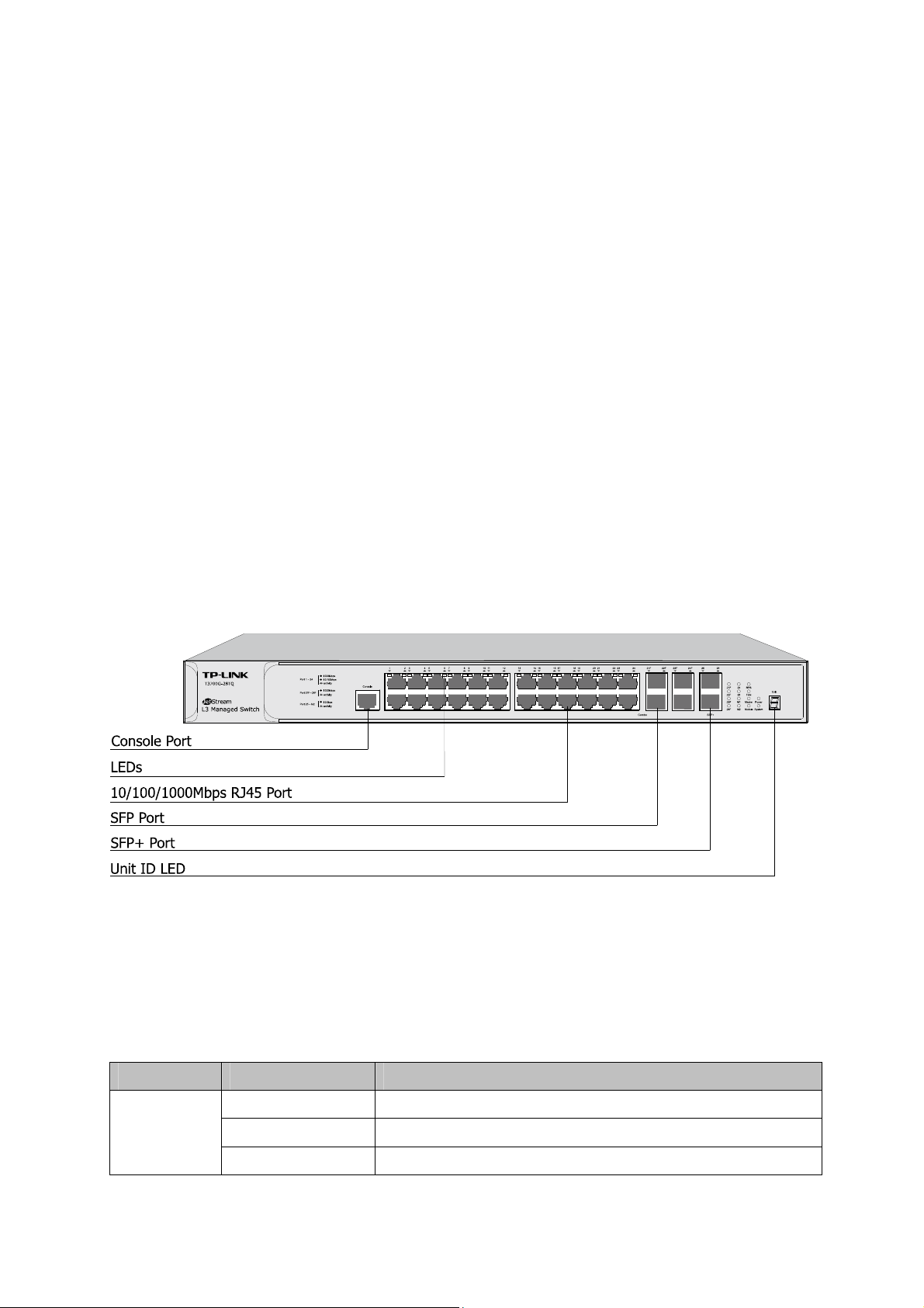
2.3.1 Front Panel
Figure 2-1 Front Panel
The following parts are located on the front panel of the switch:
Console Port: Designed to connect with the serial port of a computer or terminal for monitoring
and configuring the switch.
LEDs
LED Status Indication
On The switch is powered on.
PWR
Off The switch is powered off or power supply is abnormal.
Flashing Power supply is abnormal.
8
Page 20

LED Status Indication
System
RPS
FAN
Master
Module
Flashing The switch works properly.
On/Off The switch works improperly.
Both the built-in power supply and the redundant power
Green
supply work properly
On
Yellow
The built-in power supply works improperly, but the
redundant power supply works properly
Off The switch is not connected to any redundant power supply
Green All the fans work properly
Yellow Not all the fans work properly
On
The switch works as master in the stack system, or does not
join any stack system
Off The switch works as slave in the stack system
On(green)
Flashing(yellow)
An Interface Card is connected to the switch and works
properly
An Interface Card is connected to the switch, but works
improperly
Link/Act
(Port 1-24)
21F-24F
Green
Yellow
Flashing
Off No Interface Card is connected to the switch
A 1000Mbps device is connected to the corresponding port,
On
Flashing
but no activity
Data is being transmitted or received
A 10/100Mbps device is connected to the corresponding
On
Flashing
port, but no activity
Data is being transmitted or received
An SFP transceiver is connected to the corresponding port,
On
and it is connected to a device, but no activity
A 1000Mbps device is connected to the corresponding port
and transmitting data
An SFP transceiver is connected to the corresponding port,
Off
but it is not connected to a device, or no SFP transceiver is
connected
An SFP+ transceiver/cable is connected to the
On
corresponding port, and it is connected to a 10Gbps device,
but no activity
25, 26
Flashing
Off
A 10Gbps device is connected to the corresponding port
and transmitting data
An SFP+ transceiver/cable is connected to the
corresponding port, but it is not connected to a device, or no
SFP+ transceiver/cable is connected
9
Page 21
LED Status Indication
An SFP+ transceiver/cable is connected to the
On
corresponding port of the Interface Card, and it is connected
to a 10Gbps device, but no activity
Flashing
M1, M2
Off
10/100/1000Mbps RJ45 Ports: Port 1-24, designed to connect to a device with the bandwidth
of 10Mbps, 100Mbps or 1000Mbps. Each has a corresponding 10/100/1000Mbps LED.
SFP Ports: Port 21F-24F, designed to install the SFP transceiver. These four SFP transceiver
slots are shared with the associated RJ45 ports. The associated two ports are referred as a
“Combo” port, which means they cannot be used simultaneously, otherwise only RJ45 port
works.
SFP+ Ports: Port 25-26, designed to install the 10Gbps SFP+ transceiver/cable.
T3700G-28TQ also provides an interface card slot on the rear panel to install the expansion
card (TX432 of TP-LINK for example). If TX432 is installed, you get another two 10Gbps SFP+
A 10Gbps device is connected to the corresponding port of
the Interface Card and transferring data
An SFP+ transceiver/cable is connected to the
corresponding port of the Interface Card, but it is not
connected to a device, or no SFP+ transceiver/cable is
connected to the Interface Card, or no Interface Card is
connected
ports.
Unit ID LED: Designed to display the stack unit number of the switch. For the switch that does
not join any stack system, it displays its default unit number. To modify the default unit number,
please logon to the GUI of the switch and go to Stack→Stack Management→Switch
Renumber page.
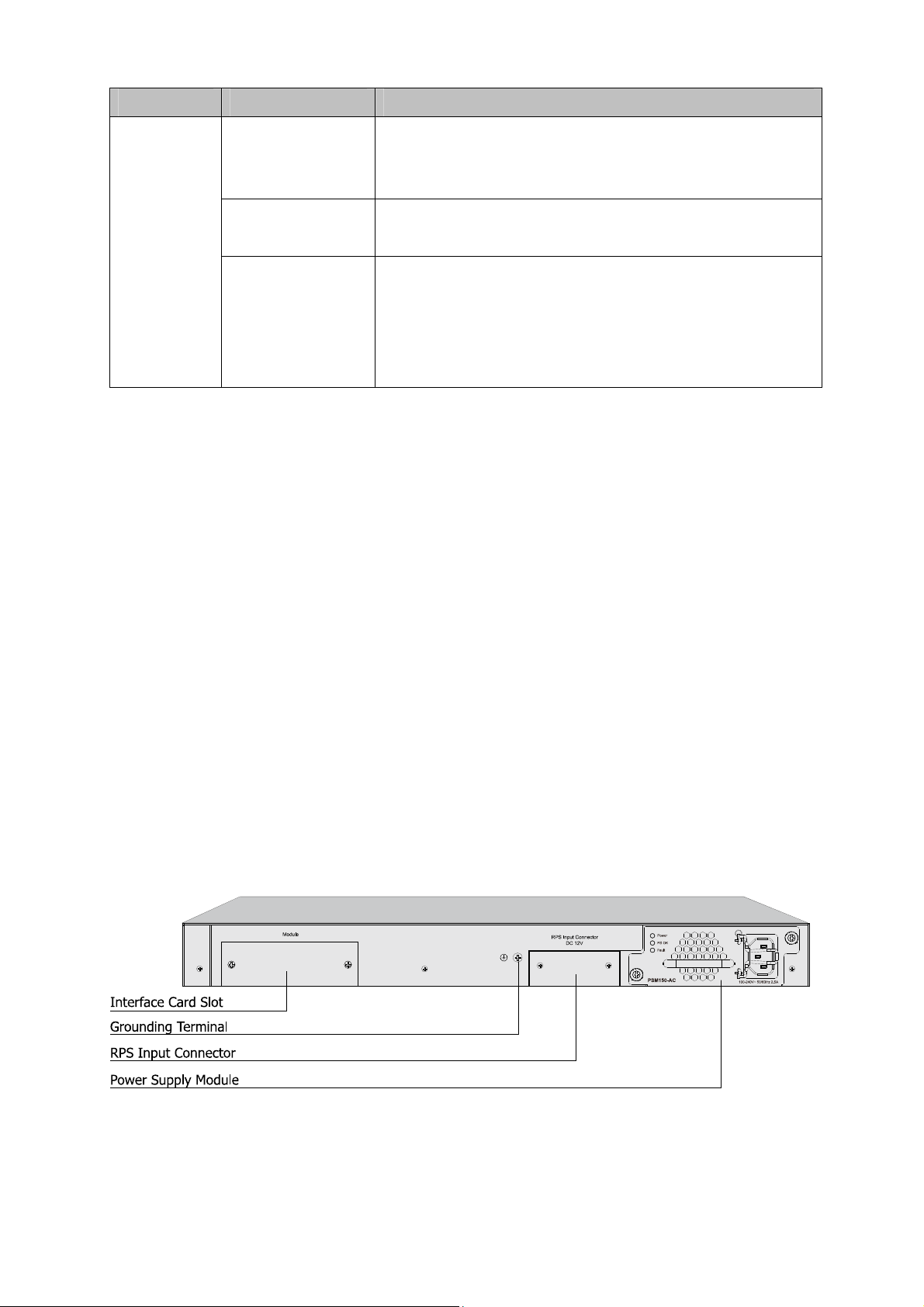
2.3.2 Rear Panel
The rear panel of T3700G-28TQ is shown as the following figure.
Figure 2-2 Rear Panel (1)
10
Page 22
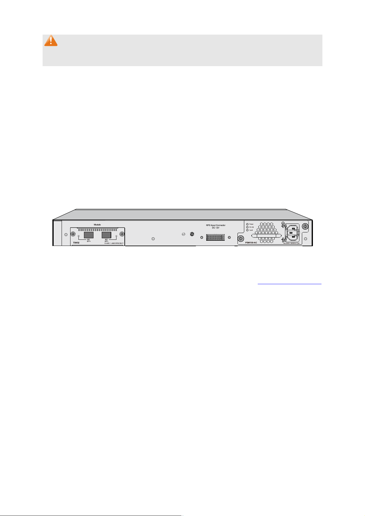
Note:
The Interface Card Slot, RPS Input Connector and AC Power Supply Module Slot are shipped with
protective covers.
Interface Card Slot: Designed to extend the interfaces. You can select an Interface Card
(TX432 of TP-LINK for example) for your switch if needed.
Grounding Terminal: T3700G-28TQ already comes with Lightning Protection Mechanism. You
can also ground the switch through the PE (Protecting Earth) cable of AC cord or with Ground
Cable. For detailed information, please refer to Installation Guide.
RPS Input Connector: Provides an interface to connect the RPS (Redundant Power Supply).
You can select an RPS (RPS150 of TP-LINK for example) for your switch if needed.
Power Supply Module Slot: Provides an interface to install the Power Supply Module. An
AC Power Supply Module PSM150-AC is provided with the switch.
With all the protective covers removed, and the Interface Card (TX432) & Power Supply Module
(PSM150-AC) inserted, the rear panel of T3700G-28TQ is shown as the following figure.
Figure 2-3 Rear Panel (2)
Return to CONTENTS
11
Page 23
Chapter 3 Login to the Switch
3.1 Login
1) To access the configuration utility, open a web-browser and type in the default address
http://192.168.0.1 in the address field of the browser, then press the Enter key.
Figure 3-1 Web-browser
Tips:
To log in to the switch, the IP address of your PC should be set in the same subnet addresses of
the switch. The IP address is 192.168.0.x ("x" is any number from 2 to 254), Subnet Mask is
255.255.255.0. For the detailed instructions as to how to do this, please refer to Appendix B.
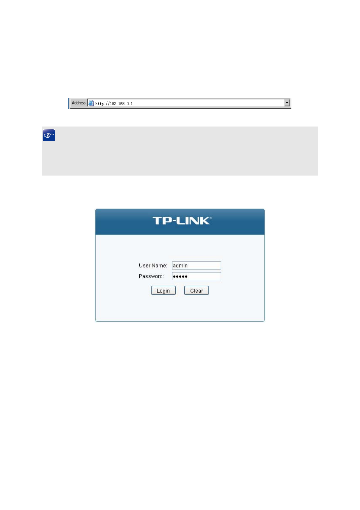
2) After a moment, a login window will appear, as shown in Figure 3-2. Enter admin for
Name and Password, both in lower case letters. Then click the Login button or press the Enter
key.
Figure 3-2 Login
the User
3.2 Configuration
After a successful login, the main page will appear as Figure 3-3, and you can configure the
function by clicking the setup menu on the left side of the screen.
12
Page 24
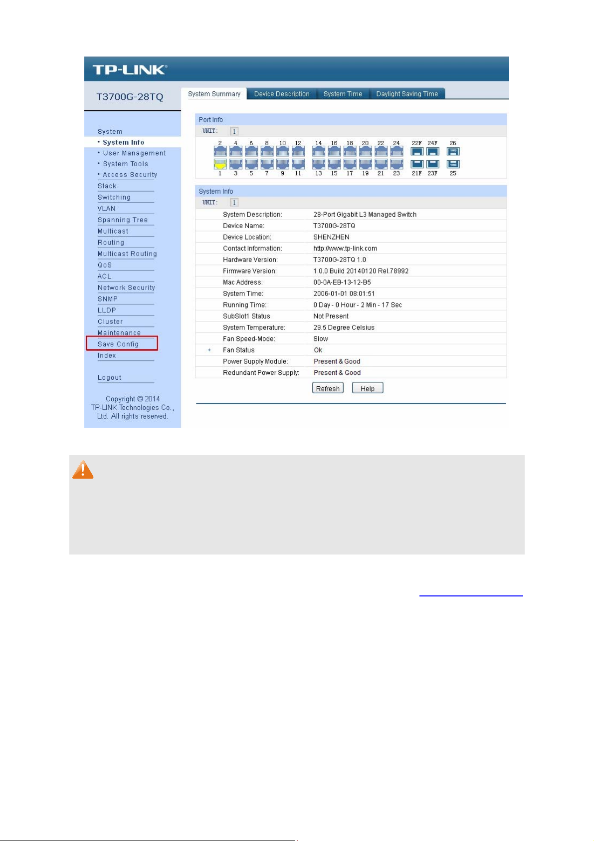
Figure 3-3 Main Setup-Menu
Note:
Clicking Apply can only make the new configurations effective before the switch is rebooted. If
you want to keep the configurations effective even the switch is rebooted, please click Save
Config. You are suggested to click Save Config before cutting off the power or rebooting the
switch to avoid losing the new configurations.
Return to CONTENTS
13
Page 25
Chapter 4 System
The System module is mainly for system configuration of the switch, including four submenus:
System Info, User Management, System Tools and Access Security.
4.1 System Info
The System Info, mainly for basic properties configuration, can be implemented on System
Summary, Device Description, System Time and Daylight Saving Time pages.
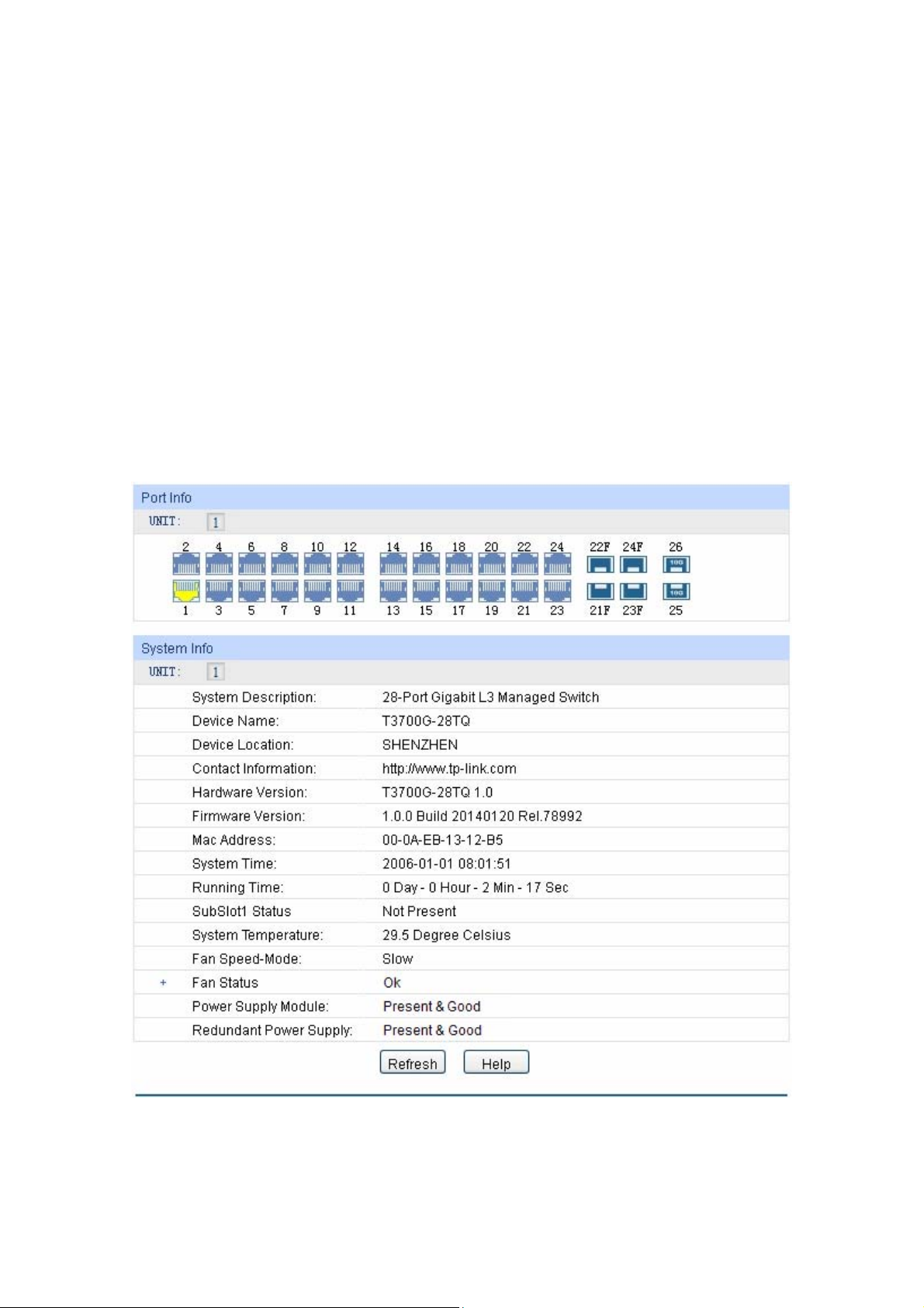
4.1.1 System Summary
On this page you can view the port connection status and the system information.
The port status diagram shows the working status of 24 10/100/1000Mbps RJ45 ports, 4
1000Mbps SFP ports and 2 10000Mbps SFP ports of the switch. Ports 27T and 28T are Combo
ports with SFP ports labeled 27F and 28F.
Choose the menu System → System Info → System Summary to load the following page.
Port Status
UNIT:
Figure 4-1 System Summary
Select the unit ID of the desired member in the stack.
14
Page 26
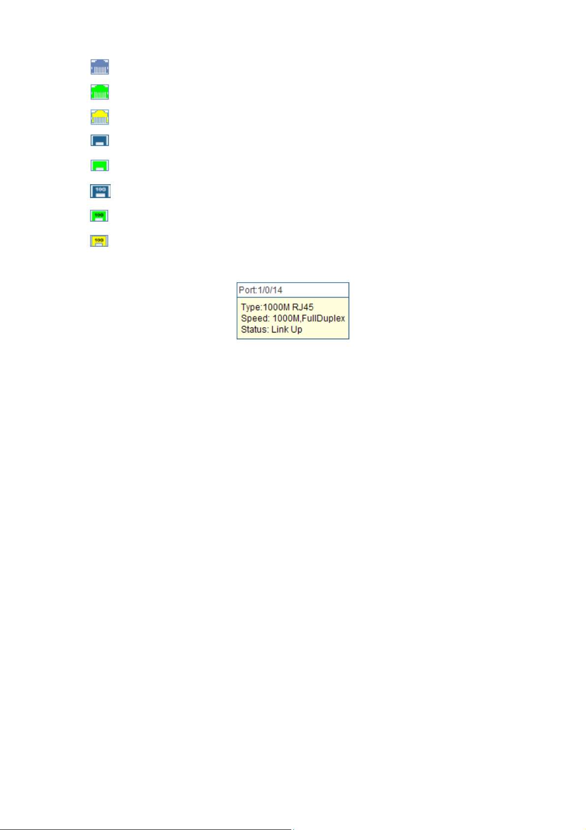
Indicates the 1000Mbps port is not connected to a device.
Indicates the 1000Mbps port is at the speed of 1000Mbps.
Indicates the 1000Mbps port is at the speed of 10Mbps or 100Mbps.
Indicates the SFP port is not connected to a device.
Indicates the SFP port is at the speed of 1000Mbps.
Indicates the SFP+ port is not connected to a device.
Indicates the SFP+ port is at the speed of 10000Mbps.
Indicates the SFP+ port is at the speed of 1000Mbps.
When the cursor moves on the port, the detailed information of the port will be displayed.
Figure 4-2 Port Information
Port Info
Port: Displays the port number of the switch.
Typ e : Displays the type of the port.
Rate: Displays the maximum transmission rate of the port.
Status: Displays the connection status of the port.
Click a port to display the bandwidth utilization on this port. The actual rate divided by theoretical
maximum rate is the bandwidth utilization.
Figure 4-3 displays the bandwidth utilization monitored
every four seconds. Monitoring the bandwidth utilization on each port facilitates you to monitor the
network traffic and analyze the network abnormities.
15
Page 27
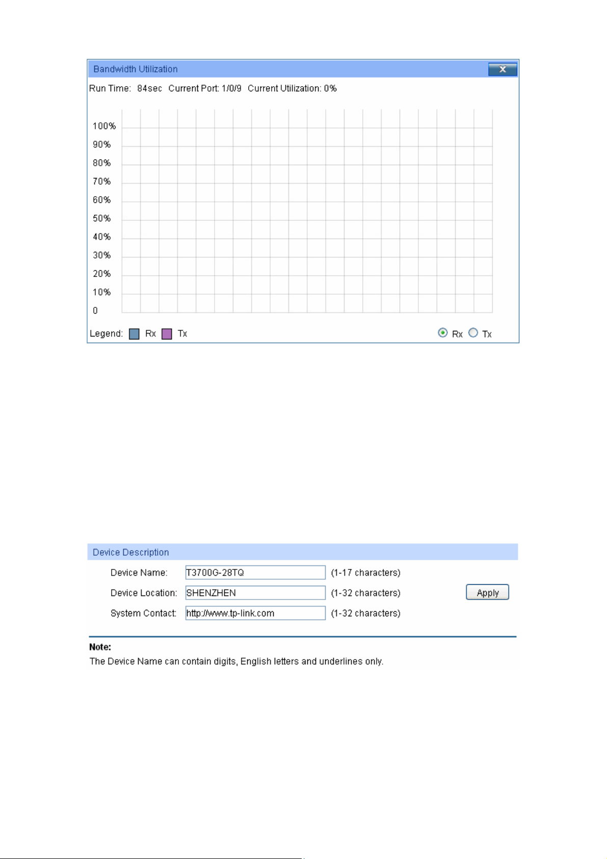
Figure 4-3 Bandwidth Utilization
Bandwidth Utilization
Rx: Select Rx to display the bandwidth utilization of receiving packets
on this port.
Tx: Select Tx to display the bandwidth utilization of sending packets
on this port.
4.1.2 Device Description
On this page you can configure the description of the switch, including device name, device location
and system contact.
Choose the menu System → System Info → Device Description to load the following page.
Figure 4-4 Device Description
The following entries are displayed on this screen:
Device Description
Device Name: Enter the name of the switch.
Device Location: Enter the location of the switch.
16
Page 28
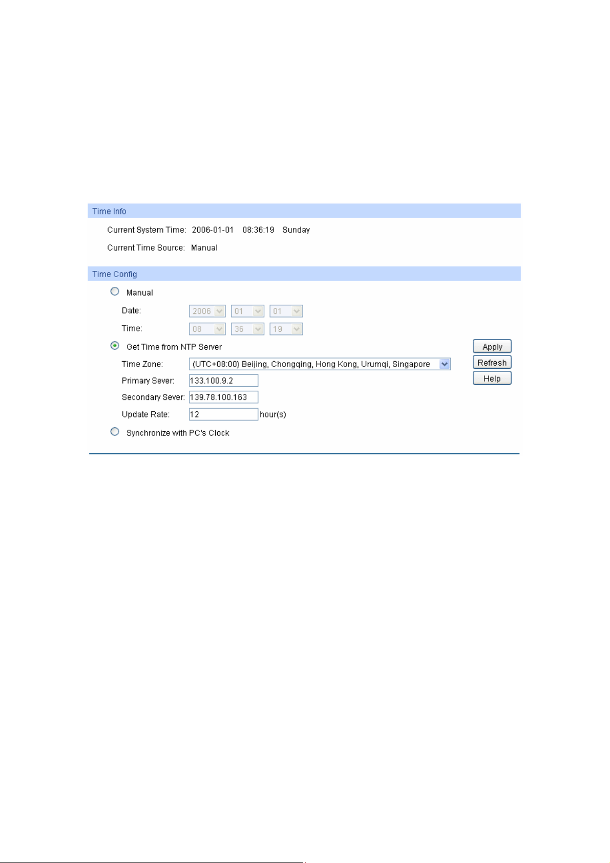
ystem Contact: Enter your contact information.
S
4.1.3 System Time
System Time is the time displayed while the switch is running. On this page you can configure the
system time and the settings here will be used for other time-based functions like ACL.
You can manually set the system time, get UTC automatically if it has connected to an NTP server
or synchronize with PC’s clock as the system time.
Choose the menu System → System Info → System Time to load the following page.
Figure 4-5 System Time
The following entries are displayed on this screen:
Time Info
Current System Time: Displays the current date and time of the switch.
Current Time Source: Displays the current time source of the switch.
Time Config
Manual: When this option is selected, you can set the date and time
manually.
Get Time from NTP
Server:
When this option is selected, you can configure the time zone
and the IP Address for the NTP Server. The switch will get UTC
automatically if it has connected to an NTP Server.
Time Zone: Select your local time.
Primary/Secondary NTP Server: Enter the IP address for
the NTP Server.
Update Rate: Specify the rate fetching time from NTP
server.
Synchronize with
PC’S Clock:
When this option is selected, the administrator PC’s clock is
utilized.
17
Page 29
Note:
1. The system time will be restored to the default when the switch is restarted and you need to
reconfigure the system time of the switch.
2. When Get Time from NTP Server is selected and no time server is configured, the switch will
get time from the time server of the Internet if it has connected to the Internet.
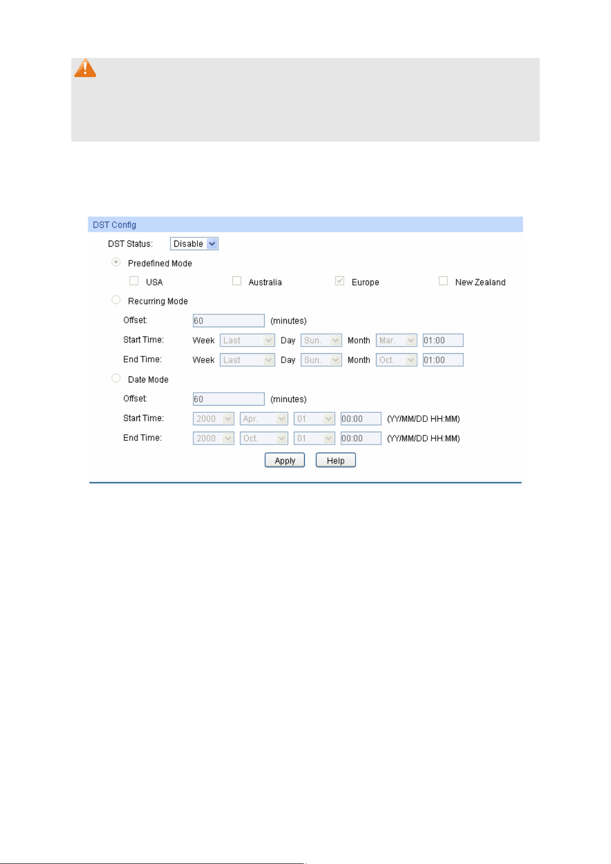
4.1.4 Daylight Saving Time
Here you can configure the Daylight Saving Time of the switch.
Choose the menu System → System Info → Daylight Saving Time to load the following page.
Figure 4-6 Daylight Saving Time
The following entries are displayed on this screen:
DST Config
DST Status: Enable or Disable DST.
Predefined Mode: Select a predefined DST configuration:
USA: Second Sunday in March, 02:00 ~ First Sunday in
November, 02:00.
Australia: First Sunday in October, 02:00 ~ First Sunday in
April, 03:00.
Europe: Last Sunday in March, 01:00 ~ Last Sunday in
October, 01:00.
New Zealand: Last Sunday in September, 02:00 ~ First
Sunday in April, 03:00.
18
Page 30
Recurring Mode: S
pecify the DST configuration in recurring mode. This
configuration is recurring in use:
Offset: Specify the time adding in minutes when Daylight
Saving Time comes.
Start/End Time: Select starting time and ending time of
Daylight Saving Time.
Date Mode: Specify the DST configuration in Date mode. This configuration
is one-off in use:
Offset: Specify the time adding in minutes when Daylight
Saving Time comes.
Start/End Time: Select starting time and ending time of
Daylight Saving Time.
Note:
1. When the DST is disabled, the predefined mode, recurring mode and date mode cannot be
configured.
2. When the DST is enabled, the default daylight saving time is of Europe in predefined mode.
4.2 User Management
User Management functions to configure the user name and password for users to log on to the
Web management page with a certain access level so as to protect the settings of the switch from
being randomly changed.
The User Management function can be implemented on User Table and User Config pages.
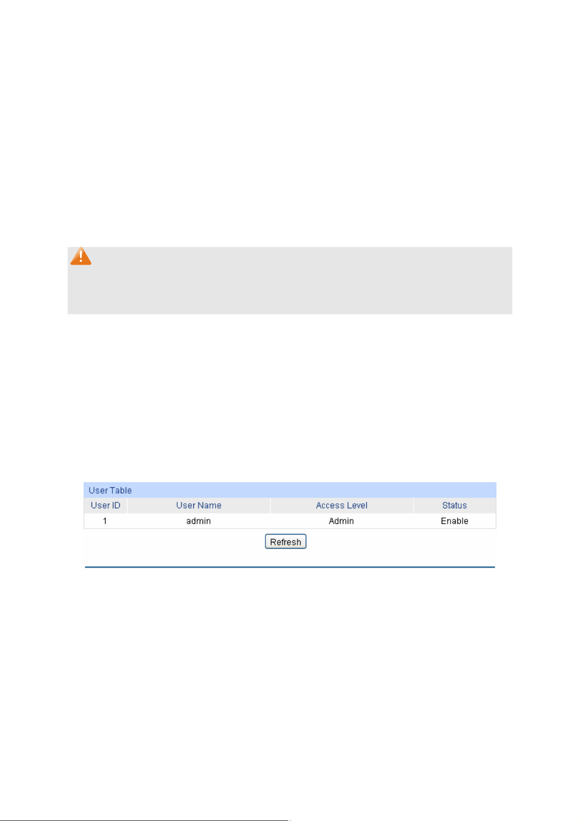
4.2.1 User Table
On this page you can view the information about the current users of the switch.
Choose the menu System → User Management → User Table to load the following page.
Figure 4-7 User Table
4.2.2 User Config
On this page you can configure the access level of the user to log on to the Web management
page. The switch provides two access levels: Guest and Admin. The guest only can view the
settings without the right to configure the switch; the admin can configure all the functions of the
switch. The Web management pages contained in this guide are subject to the admin’s login without any
explanation.
Choose the menu System → User Management → User Config to load the following page.
19
Page 31

Figure 4-8 User Config
The following entries are displayed on this screen:
User Info
User Name: Create a name for users’ login.
Access Level: Select the access level to login.
Admin: Admin can edit, modify and view all the settings of
different functions.
Guest: Guest only can view the settings without the right to
edit and modify.
User Status: Select Enable/Disable the user configuration.
Password: Type a password for users’ login.
Confirm Password: Retype the password.
Password Display
Mode:
Select password display mode:
Admin: Displays the password with plaintext in configure file.
Cipher: Displays the password with ciphertext .
User Table
Select: Select the desired entry to delete the corresponding user
information. It is multi-optional The current user information can’t
be deleted.
User ID, Name,
Access Level and
Displays the current user ID, user name, access level and user
status.
status:
20
Page 32

Operation:
Click the Edit button of the desired entry, and you can edit the
corresponding user information. After modifying the settings,
please click the Modify button to make the modification effective.
Access level and user status of the current user information can’t
be modified.
4.3 System Tools
The System Tools function, allowing you to manage the configuration file of the switch, can be
implemented on Boot Config, Config Restore, Config Backup, Firmware Upgrade, System
Reboot and System Reset pages.
4.3.1 Boot Config
On this page you can configure the boot file and the configuration file of the switch. When the
switch is powered on, it will start up with the startup image. If it fails, it will try to start up with the
backup image. If this fails too, you will enter into the bootutil menu of the switch.
When the startup process is finished, the switch will read the startup-config file. If it fails, the switch
will try to read the backup-config file. If it fails too, the switch will be restored to factory settings.
Choose the menu System → System Tools → Boot Config to load the following page.
Figure 4-9 Boot Config
The following entries are displayed on this screen:
Boot Table
Select: Select the unit(s).
Unit: Displays the unit ID.
Current Startup
Image:
Next Startup Image: Select the next startup image.
Displays the current startup image.
21
Page 33

Backup Image: Select the backup boot image.
Current S
Config:
Next Startup
Config:
Backup Config: Input the backup config filename.
Restore: Set the boot parameter to default.
tartup
Displays the current startup config filename.
Input the next startup config filename.
4.3.2 Config Restore
On this page you can upload a backup configuration file to restore your switch to this previous
configuration.
Choose the menu System → System Tools → Config Restore to load the following page.
Figure 4-10 Config Restore
The following entries are displayed on this screen:
Config Restore
Target Unit: Select the desired unit in the stack to restore it to a backup
configuration.
Import: Click the Import button to restore the backup configuration file. It
will take effect after the switch automatically reboots.
Note:
1. It will take a few minutes to restore the configuration. Please wait without any operation.
2. To avoid any damage, please don’t power down the switch while being restored.
3. After being restored, the current settings of the switch will be lost. Wrong uploaded
configuration file may cause the switch unmanaged.
4.3.3 Config Backup
On this page you can download the current configuration of the specified unit in the stack and save
it as a file to your computer for your future configuration restore.
Choose the menu System → System Tools → Config Backup to load the following page.
22
Page 34

Figure 4-11 Config Backup
The following entries are displayed on this screen:
Config Backup
Export: Click the Export button to save the current configuration as a file
to your computer. You are suggested to take this measure before
upgrading.
Note:
It will take a few minutes to backup the configuration. Please wait without any operation.
4.3.4 Firmware Upgrade
The switch system can be upgraded via the Web management page. To upgrade the system is to
get more functions and better performance. Go to http://www.tp-link.com to download the updated
firmware.
Choose the menu System→System Tools→Firmware Upgrade to load the following page.
Figure 4-12 Firmware Upgrade
Note:
1. Don’t interrupt the upgrade.
2. Please select the proper software version matching with your hardware to upgrade.
3. To avoid damage, please don't turn off the device while upgrading.
23
Page 35

4. After upgrading, the device will reboot automatically.
5. You are suggested to backup the configuration before upgrading.
4.3.5 System Reboot
On this page you can reboot the specified unit switch in the stack and return to the login page.
Please save the current configuration before rebooting to avoid losing the configuration un
Choose the menu System→System Tools→System Reboot to load the following page.
Figure 4-13 System Reboot
saved
Note:
To avoid damage, please don't turn off the device while rebooting.
4.3.6 System Reset
On this page you can reset the
cleared after the switch is reset.
Choose the menu System→System Tools→System Reset to load the following page.
Note:
After the system is reset, the switch will be reset to the default and all the settings will be cleared.
specified unit in the st
Figure 4-14 System Reset
ack to the default. All the settings will be
4.4 Access Security
Access Security provides different security measures for the remote login so as to enhance the
configuration manage
SSH Config pages.
4.4.1 Access Control
On this page you can control the users logging on to the Web management page to enhance the
configuration management security. The definitions of Admin and Guest r
Management. This function only applies to Web, SNMP, Telnet, SSL and SSH.
ment security. It can be implemented on Access Control, SSL Config and
to 4.2 User
efer
24
Page 36

Choose the menu System→Access Security→Access Control to load the following page.
Figure 4-15 Access Control
The following entries are displayed on this screen:
Access Control Config
Control Mode: Select the control mode for users to log on to the Web
management page.
IP-based: Select this option to limit the IP-range of the users
for login.
MAC-based: Select this option to limit the MAC Address of
the users for login.
Port-based: Select this option to limit the ports for login.
IP Address& Mask:
These fields can be available for configuration only when
IP-based mode is selected. Only the users within the IP-range
you set here are allowed for login.
MAC Address: The field can be available for configuration only when MAC-based
mode is selected. Only the user with this MAC Address you set
here is allowed for login.
Port: The field can be available for configuration only when Port-based
mode is selected. Only the users connected to these ports you
set here are allowed for login.
Session Config
Session Timeout: If you do nothing with the Web management page within the
timeout time, the system will log out automatically. If you want to
reconfigure, please login again.
Access User Number
Number Control: Select Enable/Disable the Number Control function.
25
Page 37

Admin Number: Enter the maximum num
management page as Admin.
Guest Number: Enter the maximum number of the users logging on to the Web
management page as Guest.
ber of the users logging on to the Web
4.4.2 SSL Config
SSL (Secure Sockets Layer), a security protocol, is to provide a secure connection for the
application layer protocol (e.g. HTTP) communication based on TCP. SSL is widely used to secure
the data transmission between the Web browser and servers. It is mainly applied through
ecommerce and online banking.
SSL mainly provides the following services:
1. Authenticate the users and the servers based on the certificates to ensure the data are
transmitted to the correct users and servers;
2. Encrypt the data transmission to prevent the data being intercepted;
3. Maintain the integrality of the data to prevent the data being altered in the transmission.
Adopting asymmetrical encryption technology, SSL uses key pair to encrypt/decrypt information. A
key pair refers to a public key (contained in the certificate) and its corresponding private key. By
default the switch has a certificate (self-signed certificate) and a corresponding private key. The
Certificate/Key Download function enables the user to replace the default key pair.
After SSL is effective, you can log on to the Web management page via https://192.168.0.1
the first time you use HTTPS connection to log into the switch with the default certificate, you will
be prompted that “The security certificate presented by this website was not issued by a trusted
certificate authority” or “Certificate Errors”. Please add this certificate to trusted certificates or
continue to this website.
On this page you can configure the SSL function.
Choose the menu System→Access Security→SSL Config to load the following page.
. For
Figure 4-16 SSL Config
The following entries are displayed on this screen:
26
Page 38

Global Config
SSL: Select Enable/Disable the SSL function on the switch.
Certificate Download
Certificate File: Select the desired certificate to download to the switch. The
certificate must be BASE64 encoded.
Key Download
Key File: Select the desired SSL Key to download to the switch. The key
must be BASE64 encoded.
Note:
1. The SSL certificate and key downloaded must match each other; otherwise the HTTPS
connection will not work.
2. The SSL certificate and key downloaded will not take effect until the switch is rebooted.
3. To establish a secured connection using https, please enter https:// into the URL field of the
browser.
4. It may take more time for https connection than that for http connection, because https
connection involves authentication, encryption and decryption etc.
4.4.3 SSH Config
As stipulated by IFTF (Internet Engineering Task Force), SSH (Secure Shell) is a security protocol
established on application and transport layers. SSH-encrypted-connection is similar to a telnet
connection, but essentially the old telnet remote management method is not safe, because the
password and data transmitted with plain-text can be easily intercepted. SSH can provide
information security and powerful authentication when you log on to the switch remotely through
an insecure network environment. It can encrypt all the transmission data and prevent the
information in a remote management being leaked.
Comprising server and client, SSH has two versions, V1 and V2 which are not compatible with
each other. In the communication, SSH server and client can auto-negotiate the SSH version and
the encryption algorithm. After getting a successful negotiation, the client sends authentication
request to the server for login, and then the two can communicate with each other after successful
authentication. This switch supports SSH server and you can log on to the switch via SSH
connection using SSH client software.
SSH key can be downloaded into the switch. If the key is successfully downloaded, the certificate
authentication will be preferred for SSH access to the switch.
Choose the menu System→Access Security→SSH Config to load the following page.
27
Page 39
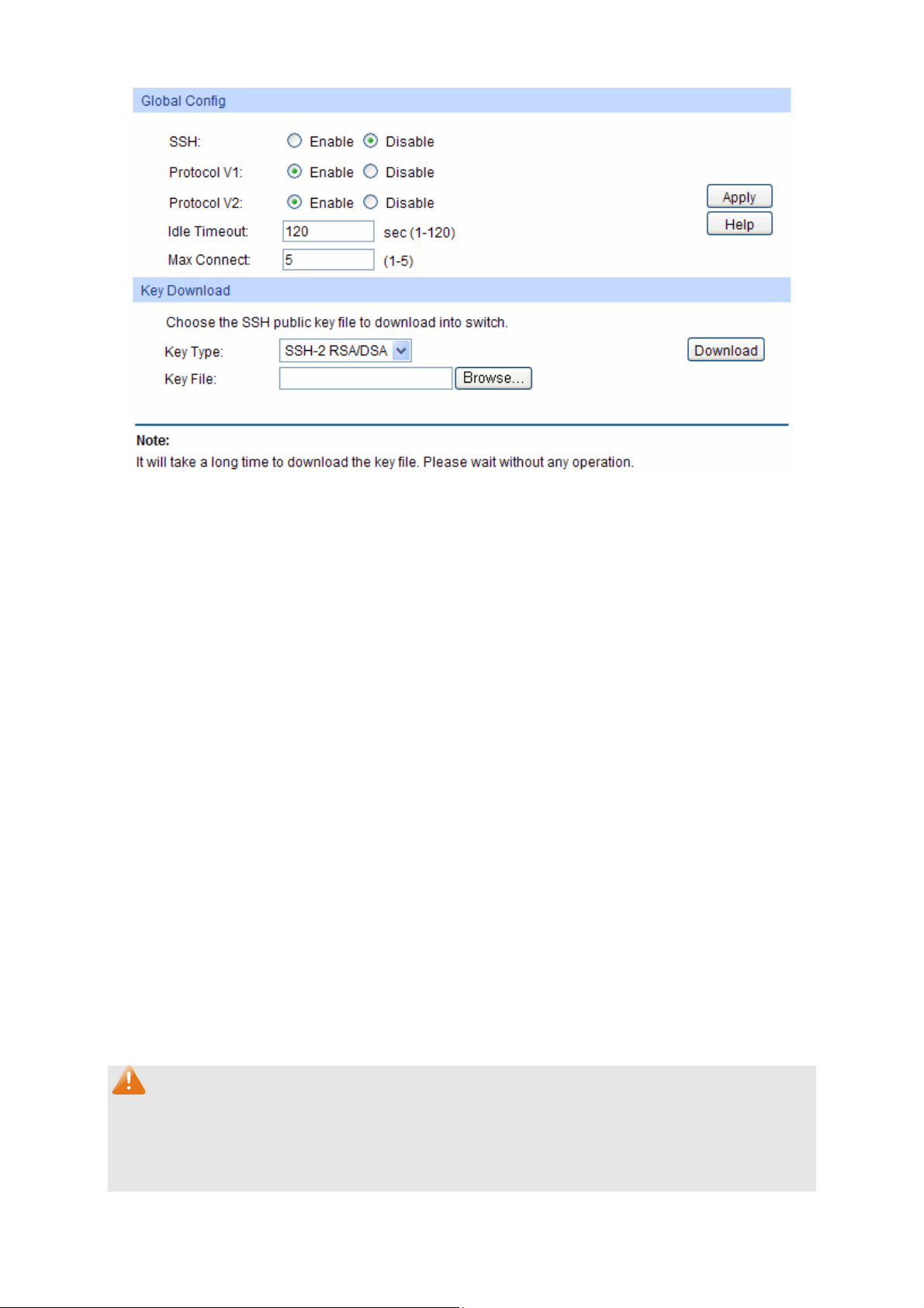
Figure 4-17 SSH Config
The following entries are displayed on this screen:
Global Config
SSH: Select Enable/Disable SSH function.
Protocol V1: Select Enable/Disable SSH V1 to be the supported protocol.
Protocol V2: Select Enable/Disable SSH V2 to be the supported protocol.
Idle Timeout: Specify the idle timeout time. The system will automatically
release the connection when the time is up. The default time is
500 seconds.
Max Connect: Specify the maximum number of the connections to the SSH
server. No new connection will be established when the number
of the connections reaches the maximum number you set. The
default value is 5.
Key Download
Key Type: Select the type of SSH Key to download. The switch supports
three types: SSH-1 RSA, SSH-2 RSA and SSH-2 DSA.
Key File: Select the desired key file to download.
Download: Click the Download button to down the desired key file to the
switch.
Note:
1. Please ensure the key length of the downloaded file is in the range of 256 to 3072 bits.
2. After the Key File is downloaded, the user’s original key of the same type will be replaced.
The wrong uploaded file will result in the SSH access to the switch via Password
authentication.
28
Page 40

Application Example 1 for SSH:
Network Requirements
1. Log on to the switch via password authentication using SSH and the SSH function is enabled
on the switch.
2. PuTTY client software is recommended.
Configuration Procedure
1. Open the software to log on to the interface of PuTTY. Enter the IP address of the switch into
Host Name field; keep the default value 22 in the Port field; select SSH as the Connection
type.
2. Click the Open button in the above figure to log on to the switch. Enter the login user name and
password, and then you can continue to configure the switch.
Application Example 2 for SSH:
Network Requirements
1. Log on to the switch via key authentication using SSH and the SSH function is enabled on the
switch.
2. PuTTY client software is recommended.
29
Page 41
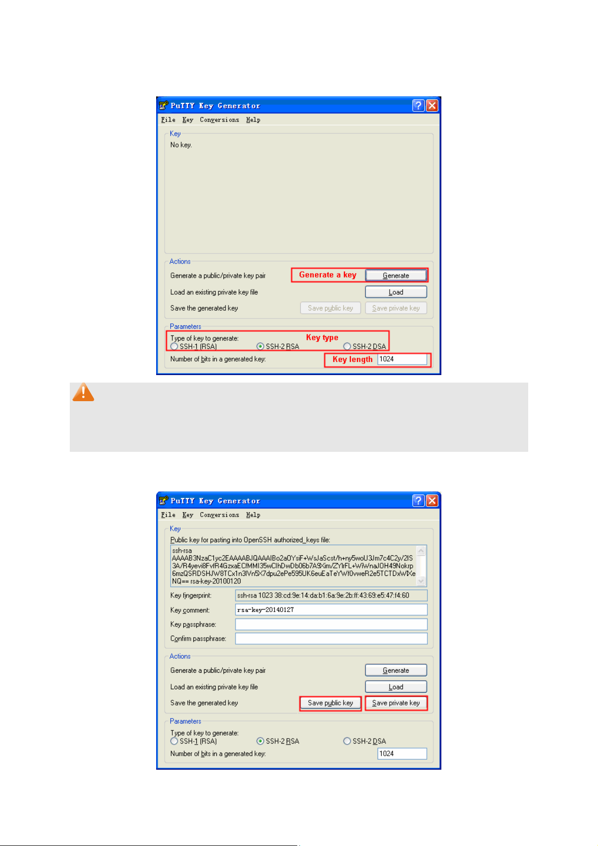
Configuration Procedure
1. Select the key type and key length, and generate SSH key.
Note:
1. The key length is in the range of 256 to 3072 bits.
2. During the key generation, randomly moving the mouse quickly can accelerate the key
generation.
2. After the key is successfully generated, please save the public key and private key to the
computer.
30
Page 42

3. On the Web management page of the switch, download the public key file saved in the
computer to the switch.
Note:
1. The key type should accord with the type of the key file.
2. The SSH key downloading can not be interrupted.
4. After the public key is downloaded, please log on to the interface of PuTTY and enter the IP
address for login.
5. Click Browse to download the private key file to SSH client software and click Open.
31
Page 43
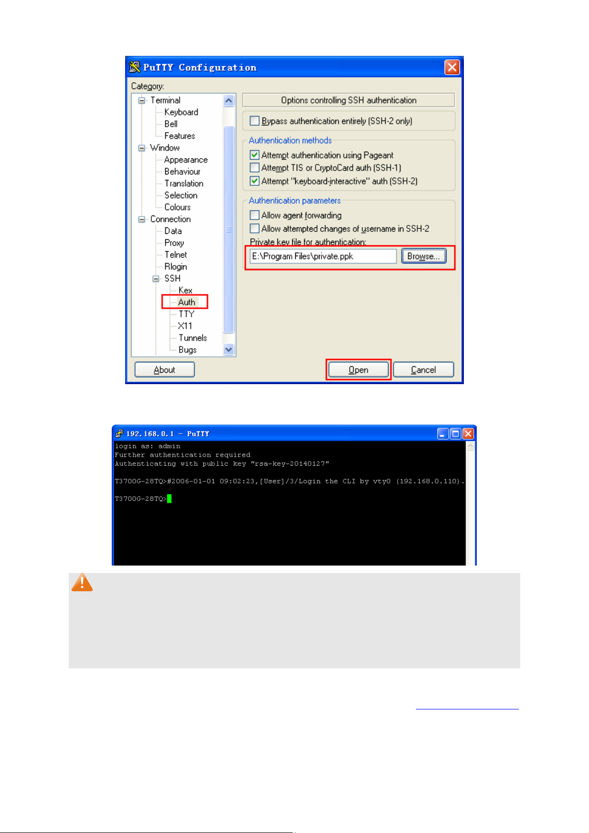
After successful authentication, please enter the login user name. If you log on to the switch
without entering password, it indicates that the key has been successfully downloaded.
Note:
Following the steps above, you have already entered the User EXEC Mode of the switch. However,
to configure the switch, you need a password to enter the Privileged EXEC Mode first. For a switch
with factory settings, the Privileged EXEC Mode password can only be configured through the
console connection. For how to configure the Privileged EXEC Mode password, please refer to the
1.1.2 Configuring the Privileged EXEC Mode Password in CLI Reference Guide.
32
Return to CONTENTS
Page 44

Chapter 5 Stack
The stack technology is to connect multiple stackable devices through their StackWise ports,
forming a stack which works as a unified system and presents as a single entity to the network in
Layer 2 and Layer 3 protocols. It enables multiple devices to collaborate and be managed as a
whole, which improves the performance and simplifies the management of the devices efficiently.
Advantages
The stack delivers the following benefits:
1. Simplified management. After stack establishment, the user can log in the stack system
through any StackWise ports of stackable devices, and manage it as a single device. You only
need to configure the stack system once instead of operating repetitive configuration on
multiple devices. Various ways such as CONSOLE, SNMP, TELNET and WEB are available
for users to manage the stack.
2. High reliability. The stack is highly reliable in following aspects:
1) The stack system is compromised of multiple devices among which one member device
works as the stack master to take charge of the operation, management and maintenance
of the stack, while the other stack members process services and keep a copy
configuration file in accordance with the master for providing backup simultaneously.
Once the stack master becomes unavailable, the remaining stack members elect a new
master among themselves instantly and automatically, which can ensure uninterrupted
services and furthermore making 1:N backup feasible. Due to the real-time configuration
and data synchronization being strictly executed, the new master can take over the
previous master to manage and maintain the stack system smoothly without affecting its
normal operation.
2) Distributed LACP (Link Aggregation Control Protocol) supports link aggregation across
devices. Since the whole stack system presents as a single device on the network,
external devices can implement LACP with the stack system by connecting to several
stack member devices simultaneously. Among the links between the stack system and
external devices, load distribution and backup can be realized to increase the reliability of
the stack system and to simplify dramatically the network topology as Figure 5-1 shows.
Figure 5-1 Distributed LACP
33
Page 45

In a ring connected stack, it can still operate normally by transforming into a daisy
chained stack when link failure occurs, which further ensures the normal operation of load
distribution and backup across devices and links as Figure 5-2 shows.
Figure 5-2 Load Distribution and Backup across Devices
3. Network scalability. Each member device in the stack system is able to process protocol
packets and forward data individually, which enables you to increase the port number and
bandwidth of the stack system by adding new member devices. The users are free to add or
remove stack members without affecting the normal running of the stack, which enables them
to protect the existed resources furthest during network upgrades.
Application Diagram
Figure 5-3 Application Diagram
34
Page 46

Stack Introduction
1. Stack Elements
1) Stack Ro le
Each device in the stack system is called stack member. Each stack member processes
services packets and plays a role which is either master or slave in the stack system. The
differences between master and slave are described as below:
Master: Indicates the device is responsible for managing the entire stack system.
Slave: Indicates the device provides backup for the master. If the master fails, the stack
will elect a new master from the remaining slaves to succeed the previous master.
2) Stack Event
Stack event indicates the global events which might happen during stack operation process,
with two options:
Merge: It occurs when two independent stacks merge into one stack because of stack link
establishment, as shown in the following figure:
Figure 5-4 Stack Merge
When stack merge occurs, the previous masters compete to be the new master. The stack
members of the defeated stack will join the winner stack as a slave to form a new stack.
Master will assign Unit Number to the newly joined members and compare their
configuration files. The members with different configurations files with the master will
download the configuration files of the master and re-configure.
Split: It occurs when stack splits into two or more stacks because of stack link failures, as
shown in the following figure:
Figure 5-5 Stack Split
After stack partition occurs, each newly established stack elects their own new master and
use the MAC address of the master as its stack MAC address. However, stack partition
probably brings about routing and forwarding problems on the network since the
partitioned stacks keep operating with the previous IP address by default, which results in
same IP address being reused in the same LAN.
2. Operation Procedure
Stack management involves these four stages: Connecting the stack members, Topology
collection, Master election, and Stack management and maintenance.
35
Page 47

1)
Connecting the stack members
To establish a stack, please physically connect the stack ports of the member devices with
cables. The stack ports of T3700-28TQ can be used for stack connection or as normal
Ethernet Gigabit port. When you want to establish a stack, the stack mode of the related ports
should be configured as "Enable". If the stack mode of the port is "Disable", then the port will
work as a normal Ethernet port.
Stack typically adopts a daisy chain topology or ring topology as shown in Figure 5-6:
Figure 5-6 Stack Connect Topology
The daisy chain topology is mainly used in a network where member devices are
distributively located.
The ring topology is more reliable than the daisy chain topology. In a daisy chained stack,
link failure can cause stack split. While in a ring connected stack, the system is able to
operate normally with a new daisy chained topology.
Note:
Establish a stack of ring or daisy chain topology with eight T3700-28TQ switches at most.
2) Topology Collection
Each member in the stack collects the topology of the whole stack by exchanging stack
discovery packets with its neighbors. Discovery packet carries topology information including
stack port connection status, unit number, priorities, MAC addresses, etc.
Each member keeps a local record of the known topology information. When the device
initializes, it only possesses the record of its own topology information. Periodically the stack
members send out their known topology information through the stack ports to its neighbors.
When the neighbors receive the information, they will update their local topology information.
After a period of time of broadcasting and updating information, all the stack members can
collect the complete topology information (known as topology convergence).
Then the switch enters the master election stage.
3) Master Election
After all members have obtained topology information (known as topology convergence), the
stack enters the master election stage. A stack always has one stack master, while the other
stack members are slaves. Master election determines the stack role of the stack members.
36
Page 48

Master election is held each time the topology changes, for example, when stack merge or
split occurs, or the stack or the current master is reset.
The master is elected based on the following rules and in the order listed:
1. The switch that is currently the stack master.
2. The switch with the highest stack member priority value.
3. The switch with the lowest MAC address.
After master election, the stack forms and enters into stack management and maintenance
stage.
Note:
1. The priority value ranges from 1 to 15. The higher the value is, the more likely the member
will be elected as the master. By default, the member priority of the switch is 5. We
recommend you manually assign the highest priority value to the switch that you prefer to
be the stack master before stack establishment.
2. The switch is non-preemptible when it joins the stack in cold-start mode, and the process
is illustrated as bellow: the switch has no stack role at its start, and it sends out discovery
messages to collect the topology of the current stack system. After the topology collection,
the switch obtains its role according to the rules above. The switch will become stack
slave if there is already a master in the stack. The master will resume its role even if the
newly joined switch has a higher priority.
4) Stack Management and Maintenance
After the stack is established, all the stack members are integrated into a virtual device in the
network and managed by the master. The following section briefly introduces the concepts
and rules involved in stack management stage.
Unit Number: When the stack is running, unit number is used to identify and manage
member devices. Unit number is unique in a stack system. The factory default unit number
of switch is 1. In order to keep its uniqueness, before establishing stack you are kindly
recommended to prepare a unit number assignment scheme and then manually configure
it on each member device.
During unit number assignment process, the master prioritizes the member devices
already carrying manually assigned unit number. If the unit number has not been used by
other stack members the member device will keep it. Otherwise, the unit number is
configured based on the following rules and in the order listed:
1. The device which was managed by the current master before the configuration will
resume its unit number.
2. The device with manually assigned unit number is prior to the device whose unit
number assignment mode is “Auto”.
3. The device with the highest stack member priority value.
4. The device with the lowest MAC address.
Note:
1. You can get the current unit number of the switch from the unit number LED on the
front panel of the switch.
2. When the stack is running, if you want to change the unit number manually, only the
unit numbers which have not been occupied by the other member devices are
available for you to choose from.
37
Page 49

Port Number Format:
The format of port number should be Unit Number/Slot Number/Port Number. Among
them:
(1) Unit Number: The default unit number of the switch is 1. If a device has joined stack
system, the unit number which the device possesses in the stack system will be kept
using as its unit number after the device leaves the stack system.
(2) Slot Number: Indicates the number of the slot the interface card is in. For
T3700G-28TQ, the front panel ports belong to slot 0. Slot number starting from 1
each represents an interface card slot.
(3) Physical Port Number: The physical port number on the switch which can be
obtained through the front panel of the switch.
For instance: Port number 2/0/3 indicates the physical port3 on the switch whose unit
number is 2.
Configuration Files Application Rules: It includes global configuration and interface
configuration two parts.
(1) The global configurations of all stack members are the same. Besides, each member
device keeps pace with the global configuration of the master device which enables
the stack system to work just like a single entity in the network. The stack system
adopts the following methods to ensure the synchronization of global configuration
files:
When the stack initializes, the master device will compare the configuration files of
each stack member and reconfigure the device whose global configuration is
different from its own, so as to ensure the global configuration of the stack members
are exactly the same.
When the stack is work normally, any global configuration of users will be recorded
to the current configuration files of master and then be synchronized to the other
members in the stack.
(2) Each stack member only saves the configuration of its own ports. Even when user
sets the configuration for all ports, the configuration will also be saved and
implemented only on the related stack member which the ports belong to.
Stack Maintenance
Stack maintenance mainly functions to monitor the join and leave of member devices,
collect the new topology at any times and maintain the current topology.
When the stack is operating normally, packets are transmitted constantly between stack
members. The switch can quickly judge the link status of the stack port via monitoring the
response of the packets. When the switch detects the link status changes, it will recollect
system topology and update topology database to ensure the normal operation of the
stack.
The events that will change the link status of the stack port which thus affecting the system
topology include: stack member failure or leave, new member's coming, link failure or
failure recovery, etc.
When the master switch fails, the stack system elects a new master from the remaining
members to succeed the previous master.
38
Page 50

5.1 Stack Management
Before configuring the stack, we highly recommend you to prepare the configuration planning with
a clear set of the role and function of each member device. Some configuration needs device
reboot to take effect, so you are kindly recommended to configure the stack at first, next connect
the devices physically after powering off them, then you can power them on and the devices will
join the stack automatically. After stack is established, users can log in the stack system through
any member devices to configure and manage it.
The stack management can be implemented on Stack Info, Stack Config and Switch Renumber
pages.
5.1.1 Stack Info
On this page you can view the basic parameters of the stack function. Choose the menu Stack
Management→Stack Info to load the following page.
Figure 5-7 Stack Info
The following entries are displayed on this screen:
Stack Config
Stack Name:
Stack MAC:
Stack Topo: Displays the current topology type of the stack. There are two
Stack Auth Mode:
Stack Member Info
Switch#: Displays the unit number of the member switch.
Displays the name of the stack.
Displays the current MAC address of the stack which usually is the
MAC address of the master switch. The stack uses it to
communicate with other devices.
options: Line and Ring. Line represents chain type connection and
Ring indicates ring type connection.
Displays the authentication mode used in stack creation.
39
Page 51

Role: Displays
the stack role of the member switch in the stack. There
are two options: Master and Slave.
MAC Address:
Displays the MAC address of the member switch.
Priority: Displays the member priority of the member switch. The higher the
value is, the more likely the member will be elected as the master.
Version: Displays the current firmware version of the member switch.
Status: Displays the stack status of the member switch.
Stack Port Info:
Stack Port: Displays the stack port number.
Status:
Displays the stack port status.
Neighbor: Displays the MAC address of the switch which is directly
connecting to the stack port.
5.1.2 Stack Config
On this page you can configure the basic parameters of the stack function.
Choose the menu Stack Management→Stack Config to load the following page.
Figure 5-8 Stack Config
The following entries are displayed on this screen:
40
Page 52

Stack Config
Stack Name:
Enter the name of the stack. The length of this field should be 1-30
characters. After the stack is established, the name of master
determines the stack name.
Stack Auth Mode:
Select the authentication mode used in stack creation. There are
three options: "None", "Simple" and "MD5".
None: Indicates no authentication mode is adopted in stack
creation.
Simple: Indicates simple plain text authentication mode is
adopted in stack creation.
MD5: Indicates MD5 authentication mode is adopted in stack
creation.
Stack Auth Key: Enter the authentication password used in stack authentication if
the Stack Auth Mode is "Simple" or "MD5".
Input Again: Retype the authentication password which should be the same
with above.
Stack Priority Config
Switch#:
Role:
The unit number of the switch.
The role of the switch in the stack as Master or Slave.
MAC Address: The unique identification of the switch.
Priority: The priority for the stack member. The priority ranges from 1 to 15.
The new priority value takes effect immediately but does not affect
the current stack master. The new priority helps determine which
stack member is elected as the new stack master when the
current stack master or the switch stack resets.
Stack Port Config
Stack Port:
Select the desired switch port. It is multi-optional.
Status: Allows you to Enable/Disable the stack feature of the specified
port.
5.1.3 Switch Renumber
In a stack system, unit number is implemented to identify and manage the member device. Unit
number is unique in a stack system. Unit number can be assigned automatically by stack system
or manually configured by users. On this page, you can configure the unit number of member
switch.
Choose the menu Stack Management→Switch Renumber to load the following page.
41
Page 53
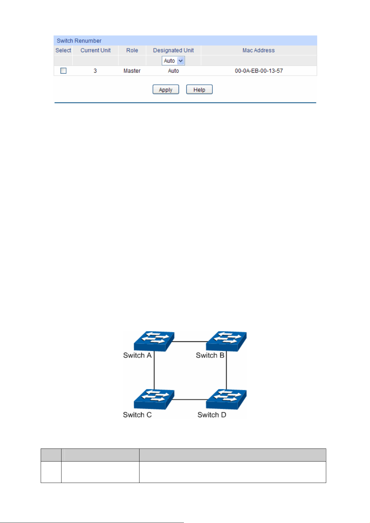
Figure 5-9 Switch Renumber
The following entries are displayed on this screen:
Switch Renumber
Select: Select the desired entry. It is multi-optional.
Current Unit: Displays the current unit number of the member switch.
Designated Unit: Configure the unit number of the member switch.
Auto: With this option selected, the member switch will be
assigned a free unit number automatically.
0-7: With this option selected, the member switch will be
assigned this unit number if it has not been used by the other
members, otherwise the member switch will be assigned a free
unit number automatically. Only the unused unit number is
available for you to choose from.
Role: The role of the device in a stack.
MAC Address:
Displays the MAC address of the member switch.
5.2 Application Example for Stack
Network Requirements
Establish a stack of ring topology with four T3700-28TQ switches.
Network Diagram
Configuration Procedure
Configure switch A, B, C and D before physically connecting them:
Step Operation Description
1 Configure the stack
name.
Optional. On Stack Management→Stack Config page,
configure the stack name.
42
Page 54

Step Operation Description
2 Configure stack port
mode.
3 Configure authentication
mode and authentication
Required. On Stack Management→Stack Config page,
configure the stack port status as "Enable".
Optional. On Stack Management→Stack Config page, select
the Stack Auth Mode and configure the Stack Auth Key.
password.
4 Configure unit number Optional. On Stack Management→Stack Renumber page,
configure the unit number of switch A, B, C and D as 1, 2, 3
and 4 respectively.
Connect the switches:
Connect switch A, B, C and D as the network diagram shows, and then power the switches on to
establish a stack.
Return to CONTENTS
43
Page 55

Chapter 6 Switching
Switching module is used to configure the basic functions of the switch, including four submenus:
Port, LAG, Traffic Monitor and MAC Address.
6.1 Port
The Port function, allowing you to configure the basic features for the port, is implemented on the
Port Config, Port Mirror, Port Security and Port Isolation pages.
6.1.1 Port Config
On this page, you can configure the basic parameters for the ports. When the port is disabled, the
packets on the port will be discarded. Disabling the port which is vacant for a long time can reduce
the power consumption effectively. And you can enable the port when it is in need.
The parameters will affect the working mode of the port, please set the parameters appropriate to
your needs.
Choose the menu Switching→Port→Port Config to load the following page.
Figure 6-1 Port Config
The following entries are displayed on this screen.
Port Config
UNIT: Select the unit ID of the desired member in the stack.
Select: Select the desired port for configuration. It is multi-optional.
Port:
Typ e :
Displays the port number.
Displays the port medium.
44
Page 56

Description:
Status: Allows you to Enable/Disable the port. When Enable is
Speed: Select the Speed mode for the port. The device connected to
Duplex: Select the Duplex mode for the port. When 'Auto' is selected,
Flow Control: Allows you to Enable/Disable the Flow Control feature. When
LAG: Displays the LAG number which the port belongs to.
Note:
1. The switch can not be managed through the disabled port. Please enable the port which is
used to manage the switch.
Give a description to the port for identification.
selected, the port can forward the packets normally.
the switch should be in the same Speed and Duplex mode with
the switch. When 'Auto' is selected, the Speed mode will be
determined by auto negotiation
the Duplex mode will be determined by auto negotiation.
Flow Control is enabled, the switch can synchronize the speed
with its peer to avoid the packet loss caused by congestion.
.
2. The parameters of the port members in a LAG should be set as the same.
6.1.2 Port Mirror
Port Mirror, the packets obtaining technology, functions to forward copies of packets from
one/multiple ports (mirrored port) to a specific port (mirroring port). Usually, the mirroring port is
connected to a data diagnose device, which is used to analyze the mirrored packets for monitoring
and troubleshooting the network.
Choose the menu Switching→Port→Port Mirror to load the following page.
Figure 6-2 Mirror Session List
45
Page 57

r
The following entries are displayed on this screen.
Mirror Session List
Session: This column displays the mirror session number.
Destination: This column displays the mirroring port.
Mode: This column displays the mirror mode.
Source: This column displays the mirrored ports.
Operation: You can configure the mirror session by clicking the "Edit", or clea
the mirror session configuration by clicking the "Clear".
Click Edit button to modify the settings of the corresponding session in the following page. Click
Clear button to clear the configuration of the corresponding session.
Figure 6-3 Port Mirror Config
46
Page 58

The following entries are displayed on this screen.
Mirror Session
Session: Displays session number.
Destination Port
Destination Port: Input or select a physical port from the port panel as the mirroring
port.
Source Port
Select: Select the desired port as a mirrored port. It is multi-optional.
Port: Displays the port number.
Ingress: Select Enable/Disable the Ingress feature. When the Ingress is
enabled, the incoming packets received by the mirrored port will be
copied to the mirroring port.
Egress: Select Enable/Disable the Egress feature. When the Egress is
enabled, the outgoing packets sent by the mirrored port will be
copied to the mirroring port.
LAG: Displays the LAG number which the port belongs to. The LAG
member cannot be selected as the mirrored port or mirroring port.
Note:
1. The LAG member can not be selected as the mirrored port or mirroring port.
2. A port can not be set as the mirrored port and the mirroring port simultaneously.
3. The Port Mirror function can take effect span the multiple VLANs.
6.1.3 Port Security
MAC Address Table maintains the mapping relationship between the port and the MAC address of
the connected device, which is the base of the packet forwarding. The capacity of MAC Address
Table is fixed. MAC Address Attack is the attack method that the attacker takes to obtain the
network information illegally. The attacker uses tools to generate the cheating MAC address and
quickly occupy the MAC Address Table. When the MAC Address Table is full, the switch will
broadcast the packets to all the ports. At this moment, the attacker can obtain the network
information via various sniffers and attacks. When the MAC Address Table is full, the packets
traffic will flood to all the ports, which results in overload, lower speed, packets drop and even
breakdown of the system.
Port Security is to protect the switch from the malicious MAC Address Attack by limiting the
maximum number of MAC addresses that can be learned on the port. The port with Port Security
feature enabled will learn the MAC address dynamically. When the learned MAC address number
reaches the maximum, the port will stop learning. Thereafter, the other devices with the MAC
address unlearned can not access to the network via this port.
Choose the menu Switching→Port→Port Security to load the following page.
47
Page 59
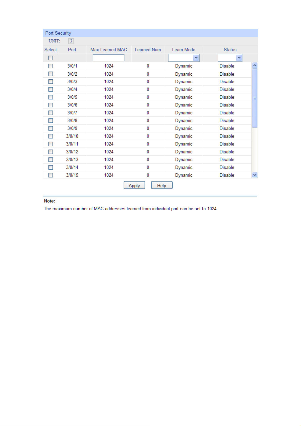
Figure 6-4 Port Security
The following entries are displayed on this screen:
Port Security
UNIT: Select the unit ID of the desired member in the stack.
Select: Select the desired port for Port Security configuration. It is
multi-optional.
Port: Displays the port number.
Max Learned MAC: Specify the maximum number of MAC addresses that can be
learned on the port.
Learned Num: Displays the number of MAC addresses that have been learned
on the port.
Learn Mode: Select the Learn Mode for the port.
Dynamic: When Dynamic mode is selected, the learned
MAC address will be deleted automatically after the aging
time.
Static: When Static mode is selected, the learned MAC
address will be out of the influence of the aging time and can
only be deleted manually. The learned entries will be cleared
after the switch is rebooted.
Permanent: When Permanent mode is selected, the
learned MAC address will be out of the influence of the
48
Page 60

aging time and can only be deleted manually. The learned
entries will be saved even the switch is rebooted.
Status: Select Enable/Disable the Port Security feature for the port.
Note:
1. The Port Security function is disabled for the LAG port member. Only the port is removed from
the LAG, will the Port Security function be available for the port.
2. The Port Security function is disabled when the 802.1X function is enabled.
6.1.4 Port Isolation
Port Isolation provides a method of restricting traffic flow to improve the network security by
forbidding the port to forward packets to the ports that are not on its forward portlist.
Choose the menu Switching→Port→Port Isolation to load the following page.
Figure 6-5 Port Isolation Config
The following entries are displayed on this screen:
Port Isolation List
UNIT: Select the unit ID of the desired member in the stack.
Port: Display the port number.
Forward Portlist: Display the forward list.
Click the Edit button to configure the port isolation list in the following page:
49
Page 61

Figure 6-6 Port Isolation Config
Port Isolation Config
UNIT: Select the unit ID of the desired member in the stack.
Port: Select the port number to set its forward list. It is multi-optional.
Forward Portlist: Select the port that to be forwarded to. It is multi-optional.
Click the Back button to go back to the port isolation list.
6.2 LAG
LAG (Link Aggregation Group) is to combine a number of ports together to make a single
high-bandwidth data path, so as to implement the traffic load sharing among the member ports in
the group and to enhance the connection reliability.
For the member ports in an aggregation group, their basic configuration must be the same. The
basic configuration includes STP, QoS, GVRP, VLAN, port attributes, MAC Address Learning
mode and other associated settings. The further explains are as following:
If the ports, which are enabled for the IGMP, IGMP Snooping, GVRP, 802.1Q VLAN, Voice
VLAN, STP, QoS, Port Isolation, DHCP Snooping and Port Configuration (Speed, Flow
Control), are in a LAG, their configurations should be the same.
The ports, which are enabled for the Port Security, Port Mirror, MAC Address Filtering,
Static MAC Address Binding, 802.1X Authentication, IP Source Guard, half-duplex and
Routed Port can not be added to the LAG.
It’s not suggested to add the ports with ARP Inspection and DoS Defend enabled to the
LAG.
50
Page 62
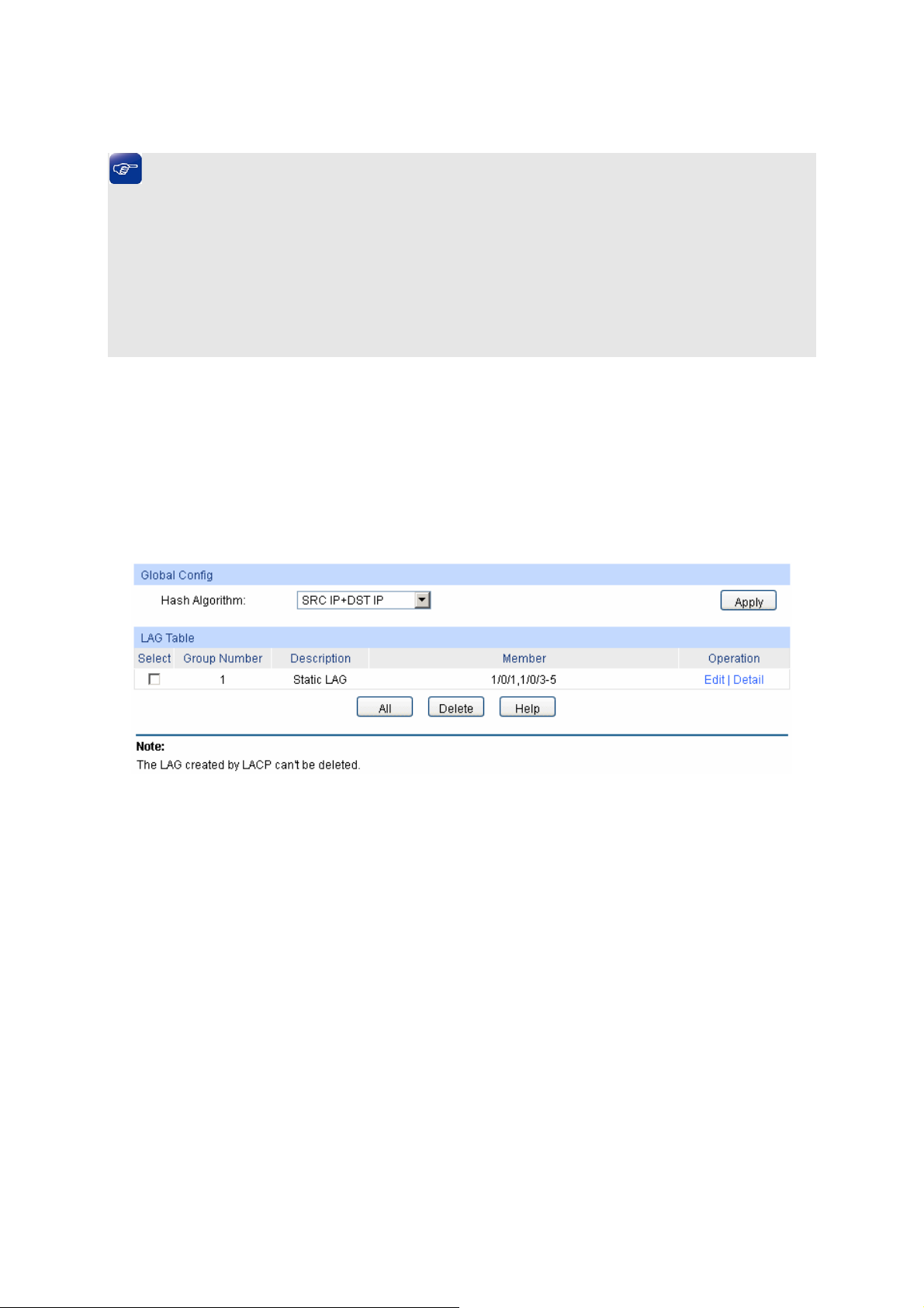
If the LAG is
needed, you are suggested to configure the LAG function here before configuring the
other functions for the member ports.
Tips:
1. Calculate the bandwidth for a LAG: If a LAG consists of the four ports in the speed of
1000Mbps Full Duplex, the whole bandwidth of the LAG is up to 8000Mbps (2000Mbps * 4)
because the bandwidth of each member port is 2000Mbps counting the up-linked speed of
1000Mbps and the down-linked speed of 1000Mbps.
2. The traffic load of the LAG will be balanced among the ports according to the Aggregate
Arithmetic. If the connections of one or several ports are broken, the traffic of these ports will
be transmitted on the normal ports, so as to guarantee the connection reliability.
Depending on different aggregation modes, aggregation groups fall into two types: Static LAG
and LACP Config. The LAG function is implemented on the LAG Table, Static LAG and LACP
Config configuration pages.
6.2.1 LAG Table
On this page, you can view the information of the current LAG of the switch.
Choose the menu Switching→LAG→LAG Table to load the following page.
Figure 6-7 LAG Table
The following entries are displayed on this screen:
Global Config
Hash Algorithm: Select the applied scope of aggregate hash arithmetic,
which results in choosing a port to transfer the packets.
SRC MAC + DST MAC: When this option is selected,
the Aggregate Arithmetic will apply to the source and
destination MAC addresses of the packets.
SRC IP + DST IP: When this option is selected, the
Aggregate Arithmetic will apply to the source and
destination IP addresses of the packets.
LAG Table
Select: Select the desired LAG. It is multi-optional.
Group Number: Displays the LAG number here.
Description: Displays the description of LAG.
51
Page 63
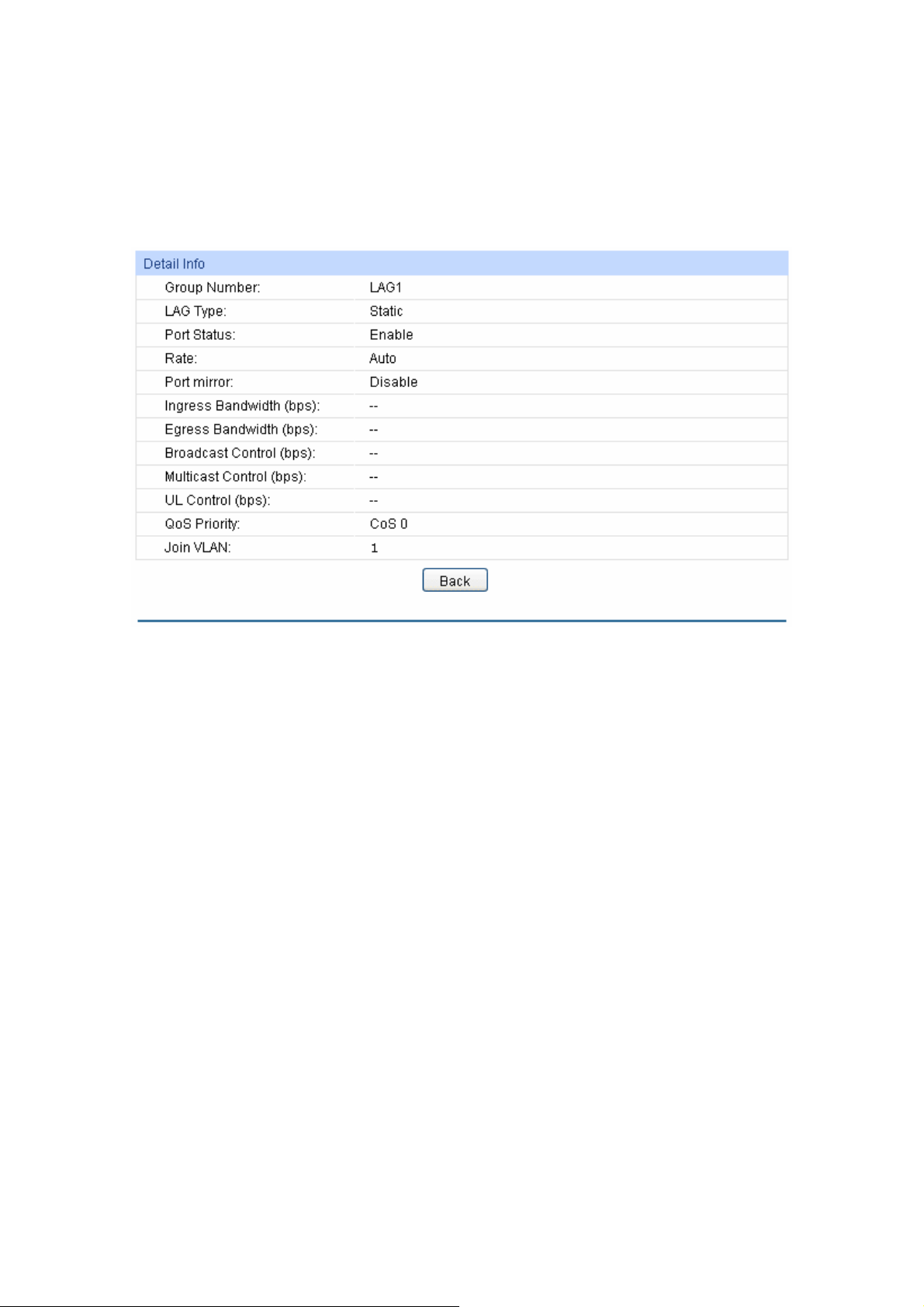
Member: Displays the LAG member
Operation: Allows you to view or modify the information for each LAG.
Edit: Click to modify the settings of the LAG.
Detail: Click to get the information of the LAG.
Click the Detail button for the detailed information of your selected LAG.
.
Figure 6-8 Detail Information
6.2.2 Static LAG
On this page, you can manually configure the LAG. The LACP feature is disabled for the member
ports of the manually added Static LAG.
Choose the menu Switching→LAG→Static LAG to load the following page.
52
Page 64

f
Figure 6-9 Static LAG Config
The following entries are displayed on this screen:
LAG Config
Group Number: Select a Group Number for the LAG.
Description: Displays the description of the LAG for identification.
Member Port
UNIT: Select the unit ID of the desired member in the stack.
Member Port: Select the port as the LAG member. Clearing all the ports o
the LAG will delete this LAG.
Tips:
1. The LAG can be deleted by clearing its all member ports.
2. A port can only be added to a LAG. If a port is the member of a LAG or is dynamically
aggregated as the LACP member, the port number will be displayed in gray and can not be
selected.
6.2.3 LACP Config
LACP (Link Aggregation Control Protocol) is defined in IEEE802.3ad/802.1ax and enables the
dynamic link aggregation and disaggregation by exchanging LACP packets with its partner. The
switch can dynamically group similarly configured ports into a single logical link, which will highly
extend the bandwidth and flexibly balance the load.
With the LACP feature enabled, the port will notify its partner of the system priority, system MAC,
port priority, port number and operation key (operation key is determined by the physical
properties of the port, upper layer protocol and admin key). The device with higher priority will lead
the aggregation and disaggregation. System priority and system MAC decide the priority of the
device. The smaller the system priority, the higher the priority of the device is. With the same
53
Page 65

system priority, the device owning the smaller system MAC has the higher priority. The device with
the higher priority will choose the ports to be aggregated based on the port priority, port number
and operation key. Only the ports with the same operation key can be selected into the same
aggregation group. In an aggregation group, the port with smaller port priority will be considered
as the preferred one. If the two port priorities are equal, the port with smaller port number is
preferred. After an aggregation group is established, the selected ports can be aggregated
together as one port to transmit packets.
On this page, you can configure the LACP feature of the switch.
Choose the menu Switching→LAG→LACP Config to load the following page.
Figure 6-10 LACP Config
The following entries are displayed on this screen:
Global Config
System Priority: Specify the system priority for the switch. The system priority and
MAC address constitute the system identification (ID). A lower system
priority value indicates a higher system priority. When exchanging
information between systems, the system with higher priority
determines which link aggregation a link belongs to, and the system
with lower priority adds the proper links to the link aggregation
according to the selection of its partner.
LACP Config
UNIT: Select the unit ID of the desired member in the stack.
54
Page 66

Select: Select the desired port for LACP
Port: Displays the port number.
Admin Key: Specify an Admin Key for the port. The member ports in a dynamic
aggregation group must have the same Admin Key.
Port Priority: Specify a Port Priority for the port. This value determines the priority
of the port to be selected as the dynamic aggregation group
member. The port with smaller Port Priority will be considered as the
preferred one. If the two port priorities are equal; the port with
smaller port number is preferred.
Mode: Specify LACP mode for your selected port.
Status: Enable/Disable the LACP feature for your selected port.
LAG: Displays the LAG number which the port belongs to.
configuration. It is multi-optional.
6.3 Traffic Monitor
The Traffic Monitor function, monitoring the traffic of each port, is implemented on the Traffic
Summary and Traffic Statistics pages.
6.3.1 Traffic Summary
Traffic Summary screen displays the traffic information of each port, which facilitates you to
monitor the traffic and analyze the network abnormity.
Choose the menu Switching→Traffic Monitor→Traffic Summary to load the following page.
55
Page 67

r
Figure6-11 Traffic Summary
The following entries are displayed on this screen:
Auto Refresh
Auto Refresh: Allows you to Enable/Disable refreshing the Traffic Summary
automatically.
Refresh Rate: Enter a value in seconds to specify the refresh interval.
Traffic Summary
UNIT: Select the unit ID of the desired member in the stack.
Port Select: Click the Select button to quick-select the corresponding port based
on the port number you entered.
Port: Displays the port number.
Packets Rx: Displays the number of packets received on the port. The erro
packets are not counted in.
Packets Tx: Displays the number of packets transmitted on the port.
Octets Rx: Displays the number of octets received on the port. The error octets
are counted in.
56
Page 68

s Tx: Displays the number of octets transmitted on the port.
Octet
Statistics: Click the Statistics button to view the detailed traffic statistics of the
port.
6.3.2 Traffic Statistics
Traffic Statistics screen displays the detailed traffic information of each port, which facilitates you to
monitor the traffic and locate faults promptly.
Choose the menu Switching→Traffic Monitor→Traffic Statistics to load the following page.
Figure6-12 Traffic Statistics
The following entries are displayed on this screen:
Auto Refresh
Auto Refresh: Allows you to Enable/Disable refreshing the Traffic Summary
automatically.
57
Page 69

r
r
r
r
r
r
sh Rate: Enter a value in seconds to specify the refresh interval.
Refre
Port Select
UNIT: Select the unit ID of the desired member in the stack.
Port Select: Click the Select button to quick-select the corresponding port
based on the port number you entered.
Statistics
Port: Enter a port number and click the Select button to view the traffic
statistics of the corresponding port.
Received: Displays the details of the packets received on the port.
Sent: Displays the details of the packets transmitted on the port.
Broadcast: Displays the number of good broadcast packets received o
transmitted on the port. The error frames are not counted in.
Multicast: Displays the number of good multicast packets received o
transmitted on the port. The error frames are not counted in.
Unicast: Displays the number of good unicast packets received or
transmitted on the port. The error frames are not counted in.
Alignment Errors: Displays the number of the received packets that have a bad
Frame Check Sequence (FCS) with a non-integral octet
(Alignment Error) and have a bad FCS with an integral octet
(CRC Error). The length of the packet is between 64 bytes and
1518 bytes.
UndersizePkts: Displays the number of the received packets (excluding erro
packets) that are less than 64 bytes long.
Pkts64Octets: Displays the number of the received packets (including erro
packets) that are 64 bytes long.
Pkts65to127Octets: Displays the number of the received packets (including error
packets) that are between 65 and 127 bytes long.
Pkts128to255Octets: Displays the number of the received packets (including erro
packets) that are between 128 and 255 bytes long.
Pkts256to511Octets: Displays the number of the received packets (including error
packets) that are between 256 and 511 bytes long.
Pkts512to1023Octets: Displays the number of the received packets (including erro
packets) that are between 512 and 1023 bytes long.
PktsOver1023Octets: Displays the number of the received packets (including error
packets) that are more than 1023 bytes long.
Collisions: Displays the number of collisions experienced by a port during
packet transmissions.
58
Page 70

6.4 MAC Address
The main function of the switch is forwarding the packets to the correct ports based on the
destination MAC address of the packets. Address Table contains the port-based MAC address
information, which is the base for the switch to forward packets quickly. The entries in the Address
Table can be updated by auto-learning or configured manually. Most the entries are generated and
updated by auto-learning. In the stable networks, the static MAC address entries can facilitate the
switch to reduce broadcast packets and enhance the efficiency of packets forwarding remarkably.
The address filtering feature allows the switch to filter the undesired packets and forbid its
forwarding so as to improve the network security.
The types and the features of the MAC Address Table are listed as the following:
Being kept after reboot
Typ e Configuration Way Aging out
Static
Address Table
Dynamic
Address Table
Filtering
Address Table
This function includes four submenus: Address Table, Static Address, Dynamic Address and
Filtering Address.
Manually configuring No Yes The bound MAC
Automatically
learning
Manually configuring No Yes -
Table 6-1 Types and features of Address Table
Yes No The bound MAC
(if the configuration is
saved)
Relationship between
the bound MAC
address and the port
address can not be
learned by the other
ports in the same
VLAN.
address can be learned
by the other ports in the
same VLAN.
6.4.1 Address Table
On this page, you can view all the information of the Address Table.
Choose the menu Switching→MAC Address→Address Table to load the following page.
59
Page 71

f
Figure 6-13 Address Table
The following entries are displayed on this screen:
Search Option
MAC Address: Enter the MAC address of your desired entry.
VLAN ID: Enter the VLAN ID of your desired entry.
Port: Select the corresponding port number or link-aggregation number o
your desired entry.
Typ e : Select the type of your desired entry.
All: This option allows the address table to display all the
address entries.
Static: This option allows the address table to display the static
address entries only.
Dynamic: This option allows the address table to display the
dynamic address entries only.
Filtering: This option allows the address table to display the
filtering address entries only.
UNIT: Select the unit ID of the desired member in the stack.
Address Table
UNIT: Select the unit ID of the desired member in the stack.
MAC Address: Displays the MAC address learned by the switch.
60
Page 72

r
VLAN ID: Displays the correspondi
Port: Displays the corresponding port number or link-aggregation numbe
of the MAC address.
Typ e : Displays the Type of the MAC address.
Aging Status: Displays the Aging status of the MAC address.
ng VLAN ID of the MAC address.
6.4.2 Static Address
The static address table maintains the static address entries which can be added or removed
manually, independent of the aging time. In the stable networks, the static MAC address entries
can facilitate the switch to reduce broadcast packets and remarkably enhance the efficiency of
packets forwarding without learning the address. The static MAC address learned by the port with
Port Security enabled in the static learning mode will be displayed in the Static Address Table.
Choose the menu Switching→MAC Address→Static Address to load the following page.
Figure 6-14 Static Address
The following entries are displayed on this screen:
Create Static Address
MAC Address: Enter the static MAC Address to be bound.
VLAN ID: Enter the corresponding VLAN ID of the MAC address.
UNIT: Select the unit ID of the desired member in the stack.
61
Page 73

Port: Select a port to be bound.
Search Option
Search Option: Select a Search Option from the pull-down list and click the Search
button to find your desired entry in the Static Address Table.
MAC: Enter the MAC address of your desired entry.
VLAN ID: Enter the VLAN ID number of your desired entry.
Port: Enter the Port number of your desired entry.
Static Address Table
UNIT: Select the unit ID of the desired member in the stack.
Select: Select the entry to delete or modify the corresponding port number. It
is multi-optional.
MAC Address: Displays the static MAC Address.
VLAN ID: Displays the corresponding VLAN ID of the MAC address.
Port: Displays the corresponding Port number of the MAC address. Here
you can modify the port number to which the MAC address is bound.
The new port should be in the same VLAN.
Typ e : Displays the Type of the MAC address.
Aging Status: Displays the Aging Status of the MAC address.
Note:
1. If the corresponding port number of the MAC address is not correct, or the connected port (or
the device) has been changed, the switch can not be forward the packets correctly. Please
reset the static address entry appropriately.
2. If the MAC address of a device has been added to the Static Address Table, connecting the
device to another port will cause its address not to be recognized dynamically by the switch.
Therefore, please ensure the entries in the Static Address Table are correct and valid.
3. The MAC address in the Static Address Table can not be added to the Filtering Address Table
or bound to a port dynamically.
4. This static MAC address bound function is not available if the 802.1X feature is enabled.
6.4.3 Dynamic Address
The dynamic address can be generated by the auto-learning mechanism of the switch. The
Dynamic Address Table can update automatically by auto-learning or the MAC address aging out
mechanism.
To fully utilize the MAC address table, which has a limited capacity, the switch adopts an aging
mechanism for updating the table. That is, the switch removes the MAC address entries related to
a network device if no packet is received from the device within the aging time.
On this page, you can configure the dynamic MAC address entry.
Choose the menu Switching→MAC Address→Dynamic Address to load the following page.
62
Page 74
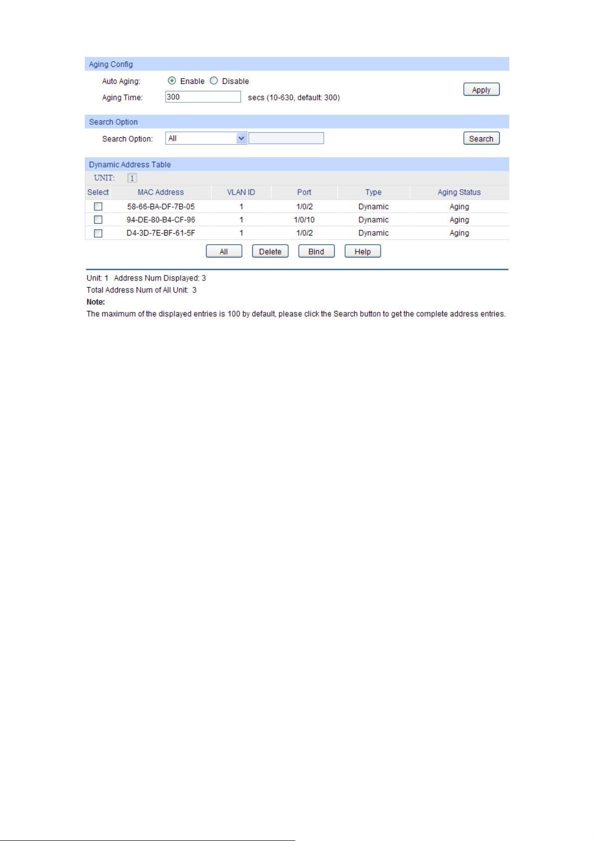
r
r
Figure 6-15 Dynamic Address
The following entries are displayed on this screen:
Aging Config
Auto Aging: Allows you to Enable/Disable the Auto Aging feature.
Aging Time: Enter the Aging Time for the dynamic address.
Search Option
Search Option: Select a Search Option from the pull-down list and click the Search
button to find your desired entry in the Dynamic Address Table.
MAC: Enter the MAC address of your desired entry.
VLAN ID: Enter the VLAN ID number of your desired entry.
Port: Enter the Port number or link-aggregation number of you
desired entry.
Dynamic Address Table
UNIT: Select the unit ID of the desired member in the stack.
Select: Select the entry to delete the dynamic address or to bind the MAC
address to the corresponding port statically. It is multi-optional.
MAC Address: Displays the dynamic MAC Address.
VLAN ID: Displays the corresponding VLAN ID of the MAC address.
Port: Displays the corresponding port number or link-aggregation numbe
of the MAC address.
Typ e : Displays the Type of the MAC address.
Aging Status: Displays the Aging Status of the MAC address.
63
Page 75
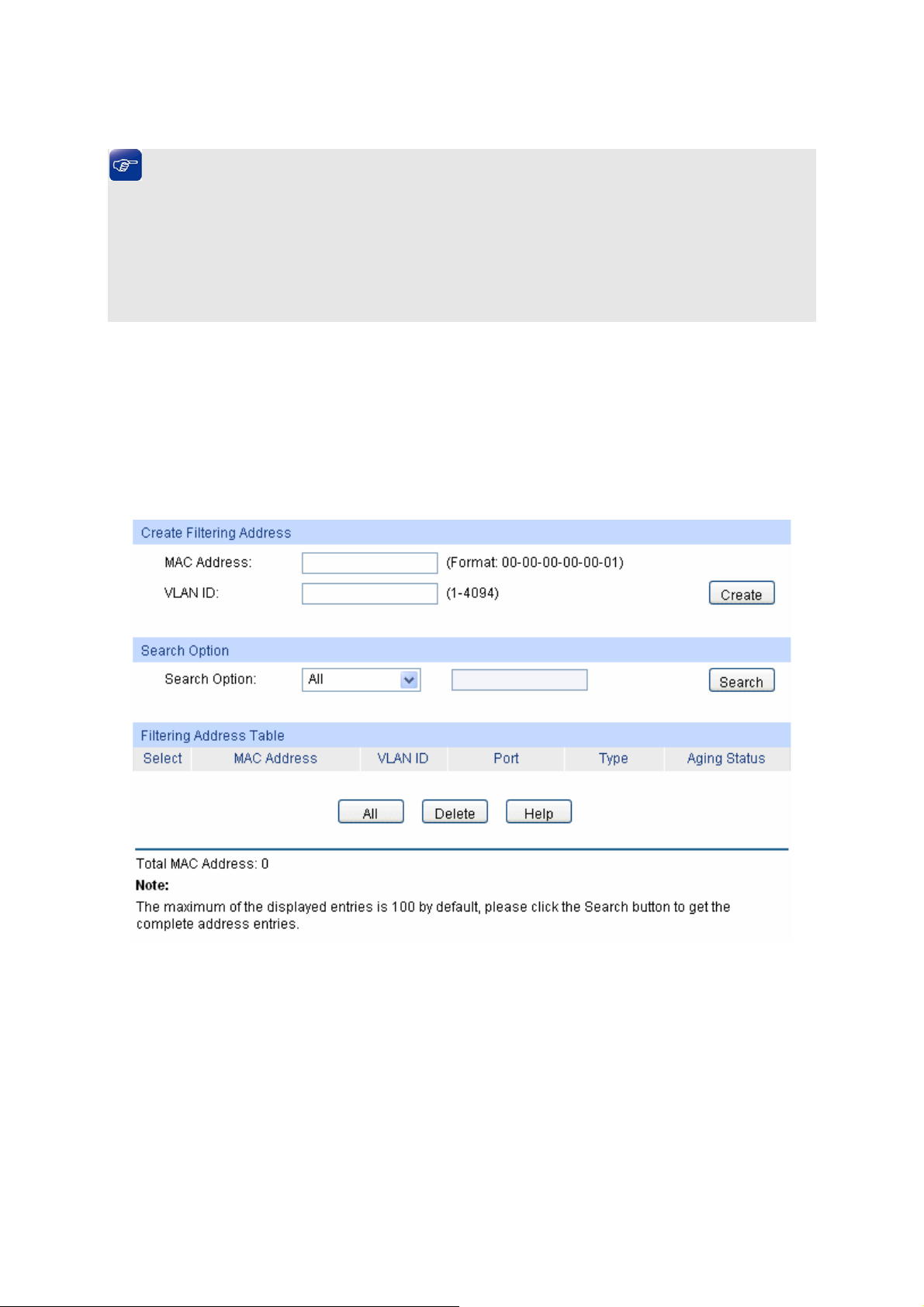
Bind: C
lick the Bind button to bind the MAC address of your selected entry
to the corresponding port statically.
Tips:
Setting aging time properly helps implement effective MAC address aging. The aging time that is
too long or too short results decreases the performance of the switch. If the aging time is too long,
excessive invalid MAC address entries maintained by the switch may fill up the MAC address table.
This prevents the MAC address table from updating with network changes in time. If the aging time
is too short, the switch may remove valid MAC address entries. This decreases the forwarding
performance of the switch. It is recommended to keep the default value.
6.4.4 Filtering Address
The filtering address is to forbid the undesired packets to be forwarded. The filtering address can
be added or removed manually, independent of the aging time. The filtering MAC address allows
the switch to filter the packets which includes this MAC address as the source address or
destination address, so as to guarantee the network security. The filtering MAC address entries
act on all the ports in the corresponding VLAN.
Choose the menu Switching→MAC Address→Filtering Address to load the following page.
Figure 6-16 Filtering Address
The following entries are displayed on this screen:
Create Filtering Address
MAC Address: Enter the MAC Address to be filtered.
VLAN ID: Enter the corresponding VLAN ID of the MAC address.
Search Option
Search Option: Select a Search Option from the pull-down list and click the Search
button to find your desired entry in the Filtering Address Table.
64 65
Page 76

MAC Address: Enter the MAC address of your desired entry.
VLAN ID: Enter the VLAN ID number of your desired entry.
Filtering Address Table
Select: Select the entry to delete the corresponding filtering address. It is
multi-optional.
MAC Address: Displays the filtering MAC Address.
VLAN ID: Displays the corresponding VLAN ID.
Port: Here the symbol “__” indicates no specified port.
Typ e : Displays the Type of the MAC address.
Aging Status: Displays the Aging Status of the MAC address.
Note:
1. The MAC address in the Filtering Address Table can not be added to the Static Address Table
or bound to a port dynamically.
2. This MAC address filtering function is not available if the 802.1X feature is enabled.
Return to CONTENTS
Page 77
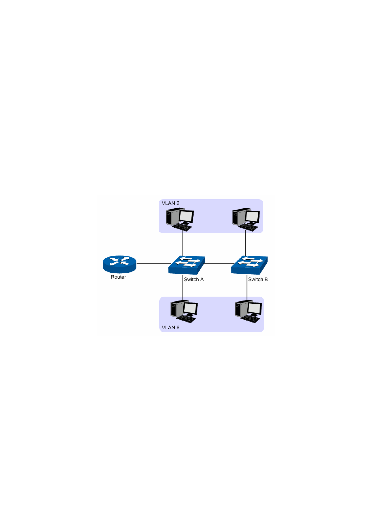
Chapter 7 VLAN
The traditional Ethernet is a data network communication technology basing on CSMA/CD (Carrier
Sense Multiple Access/Collision Detect) via shared communication medium. Through the
traditional Ethernet, the overfull hosts in LAN will result in serious collision, flooding broadcasts,
poor performance or even breakdown of the Internet. Though connecting the LANs through
switches can avoid the serious collision, the flooding broadcasts can not be prevented, which will
occupy plenty of bandwidth resources, causing potential serious security problems.
A Virtual Local Area Network (VLAN) is a network topology configured according to a logical
scheme rather than the physical layout. The VLAN technology is developed for switches to control
broadcast in LANs. By creating VLANs in a physical LAN, you can divide the LAN into multiple
logical LANs, each of which has a broadcast domain of its own. Hosts in the same VLAN
communicate with one another as if they are in a LAN. However, hosts in different VLANs cannot
communicate with one another directly. Therefore, broadcast packets are limited in a VLAN. Hosts
in the same VLAN communicate with one another via Ethernet whereas hosts in different VLANs
communicate with one another through the Internet devices such as Router, the Layer3 switch, etc.
The following figure illustrates a VLAN implementation.
Figure 7-1 VLAN implementation
Compared with the traditional Ethernet, VLAN enjoys the following advantages.
(1) Broadcasts are confined to VLANs. This decreases bandwidth utilization and improves
network performance.
(2) Network security is improved. VLANs cannot communicate with one another directly. That
is, a host in a VLAN cannot access resources in another VLAN directly, unless routers or
Layer 3 switches are used.
(3) Network configuration workload for the host is reduced. VLAN can be used to group
specific hosts. When the physical position of a host changes within the range of the VLAN,
you need not to change its network configuration.
A VLAN can span across multiple switches, or even routers. This enables hosts in a VLAN to be
dispersed in a looser way. That is, hosts in a VLAN can belong to different physical network
segment. This switch supports three ways, namely, 802.1Q VLAN, MAC VLAN and Protocol VLAN,
to classify VLANs. VLAN tags in the packets are necessary for the switch to identify packets of
different VLANs. The switch can analyze the received untagged packets on the port and match the
66
Page 78
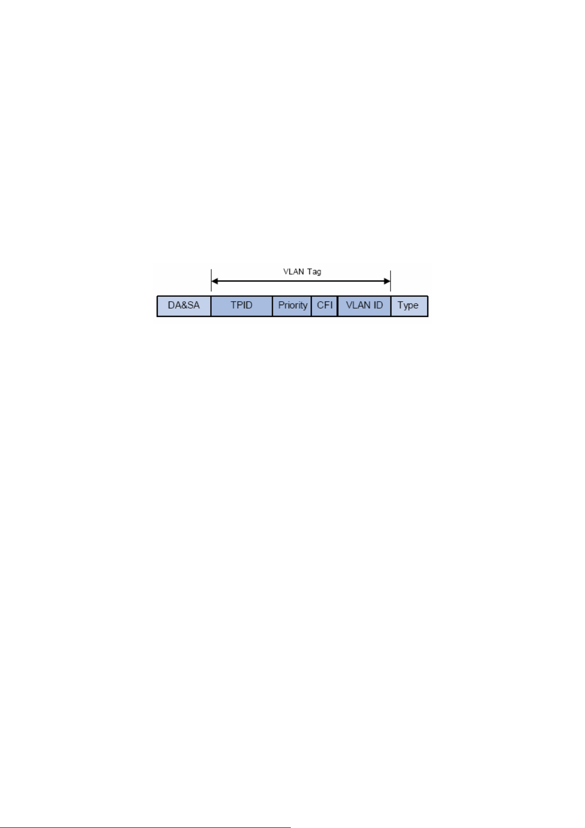
ackets with the MAC VLAN, Protocol VLAN and 802.1Q VLAN in turn. If a packet is matched, the
p
switch will add a corresponding VLAN tag to it and forward it in the corresponding VLAN.
7.1 802.1Q VLAN
VLAN tags in the packets are necessary for the switch to identify packets of different VLANs. The
switch works at the data link layer in OSI model and it can identify the data link layer encapsulation
of the packet only, so you can add the VLAN tag field into the data link layer encapsulation for
identification.
In 1999, IEEE issues the IEEE 802.1Q protocol to standardize VLAN implementation, defining the
structure of VLAN-tagged packets. IEEE 802.1Q protocol defines that a 4-byte VLAN tag is
encapsulated after the destination MAC address and source MAC address to show the information
about VLAN.
As shown in the following figure, a VLAN tag contains four fields, including TPID (Tag Protocol
Identifier), Priority, CFI (Canonical Format Indicator), and VLAN ID.
Figure 7-2 Format of VLAN Tag
(1) TPID: TPID is a 16-bit field, indicating that this data frame is VLAN-tagged. By default, it is
0x8100.
(2) Priority: Priority is a 3-bit field, referring to 802.1p priority. Refer to section “QoS & QoS
profile” for details.
(3) CFI: CFI is a 1-bit field, indicating whether the MAC address is encapsulated in the
standard format in different transmission media. This field is not described in detail in this
chapter.
(4) VLAN ID: VLAN ID is a 12-bit field, indicating the ID of the VLAN to which this packet
belongs. It is in the range of 0 to 4,095. Generally, 0 and 4,095 is not used, so the field is in
the range of 1 to 4,094.
VLAN ID identifies the VLAN to which a packet belongs. When the switch receives an
un-VLAN-tagged packet, it will encapsulate a VLAN tag with the default VLAN ID of the inbound
port for the packet, and the packet will be assigned to the default VLAN of the inbound port for
transmission.
In this User Guide, the tagged packet refers to the packet with VLAN tag whereas the untagged
packet refers to the packet without VLAN tag, and the priority-tagged packet refers to the packet
with VLAN tag whose VLAN ID is 0.
Link Types of ports
When creating the 802.1Q VLAN, you should set the link type for the port according to its
connected device. The link types of port including the following three types:
(1) ACCESS: The ACCESS port can be added in a single VLAN, and the egress rule of the
port is UNTAG. The PVID is same as the current VLAN ID. If the ACCESS port is added to
another VLAN, it will be removed from the current VLAN automatically.
(2) TRUNK: The TRUNK port can be added in multiple VLANs. The egress rule of the port is
UNTAG if the arriving packet’s VLAN tag is the same as the port’s PVID, otherwise the
egress rule is TAG. The TRUNK port is generally used to connect the cascaded network
devices for it can receive and forward the packets of multiple VLANs.
67
Page 79

(3) GENERAL: The GENERAL
port can be added in multiple VLANs and set various egress
rules according to the different VLANs. The default egress rule is UNTAG. The PVID can
be set as the VID number of any valid VLAN.
PVID
PVID (Port Vlan ID) is the default VID of the port. When the switch receives an un-VLAN-tagged
packet, it will add a VLAN tag to the packet according to the PVID of its received port and forward
the packets.
When creating VLANs, the PVID of each port, indicating the default VLAN to which the port
belongs, is an important parameter with the following two purposes:
(1) When the switch receives an un-VLAN-tagged packet, it will add a VLAN tag to the packet
according to the PVID of its received port
(2) PVID determines the default broadcast domain of the port, i.e. when the port receives UL
packets or broadcast packets, the port will broadcast the packets in its default VLAN.
Different packets, tagged or untagged, will be processed in different ways, after being received by
ports of different link types, which is illustrated in the following table.
Receiving Packets
Port Type
Forwarding Packets
Untagged Packets Tagged Packets
If the VID of packet is the
same as the PVID of the
port, the packet will be
Access
received.
If the VID of packet is not
The packet will be forwarded after
removing its VLAN tag.
the same as the PVID of
the port, the packet will
pped. be dro
If the VID of packet is
allowed by the port, the
If the arriving packet’s VLAN tag
is the same as the port’s PVID,
the packet will be forwarded after
removing its VLAN tag, otherwise
acket will be forwarded with
the p
its current VLAN tag.
Trunk
When untagged
packets are received,
the port will add the
default VLAN tag, i.e.
the PVID of the
ingress port, to the
packets.
packet will be received.
If the VID of packet is
forbidden by the port, the
packet will be dropped.
General
If the egress rule of port is TAG,
the packet will be forwarded with
its current VLAN tag.
If the egress rule of port is
UNTAG, the packet will be
forwarded after removing its
VLAN tag.
Table 7-1 Relationship between Port Types and VLAN Packets Processing
IEEE 802.1Q VLAN function is implemented on the VLAN Config and Port Config pages.
7.1.1 VLAN Config
On this page, you can view the current created 802.1Q VLAN.
Choose the menu VLAN→802.1Q VLAN→VLAN Config to load the following page.
68
Page 80

Figure 7-3 VLAN Table
To ensure the normal communication of the factory switch, the default VLAN of all ports is set to
VLAN1.
The following entries are displayed on this screen:
VLAN Table
Select:
Select the desired entry to delete the corresponding VLAN. It is
multi-optional.
VLAN ID:
Name:
Members:
Operation:
Displays the ID number of VLAN.
Displays the user-defined name of VLAN.
Displays the port members in the VLAN.
Allows you to view or modify the information for each entry.
Edit: Click to modify the settings of VLAN.
Detail: Click to get the information of VLAN.
Click Edit button to modify the settings of the corresponding VLAN. Click Create button to create a
new VLAN.
Figure 7-4 Create or Modify 802.1Q VLAN
69
Page 81

e following entries are displayed on this screen:
Th
VLAN Info
VLAN ID: Enter the ID number of VLAN.
Name: Displays the user-defined name of VLAN.
Untagged port: Displays the untagged port which is ACCESS, TRUNK or
GENERAL.
UNIT: Select the unit ID of the desired member in the stack.
Tagged port: Displays the tagged port which is TRUNK or GENERAL.
7.1.2 Port Config
Before creating the 802.1Q VLAN, please acquaint yourself with all the devices connected to the
switch in order to configure the ports properly.
Choose the menu VLAN→802.1Q VLAN→Port Config to load the following page.
Figure 7-5 802.1Q VLAN – Port Config
The following entries are displayed on this screen:
VLAN Port Config
UNIT:
Select:
Port:
Select the unit ID of the desired member in the stack.
Select the desired port for configuration. It is multi-optional.
Displays the port number.
70
Page 82

Link Type:
Select the Link Type from the pull-down list for the port.
ACCESS: The ACCESS port can be added in a single VLAN,
and the egress rule of the port is UNTAG. The PVID is same
as the current VLAN ID. If the current VLAN is deleted, the
PVID will be set to 1 by default.
TRUNK: The TRUNK port can be added in multiple VLANs.
The egress rule of the port is UNTAG if the arriving packet’s
VLAN tag is the same as the port’s PVID, otherwise the
egress rule is TAG. The PVID can be set as the VID number
of any valid VLAN.
GENERAL: The GENERAL port can be added in multiple
VLANs and set various egress rules according to the different
VLANs. The default egress rule is UNTAG. The PVID can be
set as the VID number of any valid VLAN.
PVID: Enter the PVID number of the port.
LAG: Displays the LAG to which the port belongs.
VLAN: Click the Detail button to view the information of the VLAN to
which the port belongs.
Click the Detail button to view the information of the corresponding VLAN.
Figure 7-6 View the Current VLAN of Port
The following entries are displayed on this screen:
VLAN of Port
VLAN ID:
VLAN Name:
Displays the ID number of VLAN.
Displays the user-defined description of VLAN.
Operation: Allows you to remove the port from the current VLAN.
Configuration Procedure:
Step Operation Description
1 Set the link type for
port.
2 Create VLAN. Required. On the VLAN→802.1Q VLAN→VLAN Config page,
Required. On the VLAN→802.1Q VLAN→Port Config page, set
the link type for the port basing on its connected device.
click the Create button to create a VLAN. Enter the VLAN ID and
the description for the VLAN. Meanwhile, specify its member
ports.
3 Modify/View VLAN. Optional. On the VLAN→802.1Q VLAN→VLAN Config page,
click the Edit/Detail button to modify/view the information of the
corresponding VLAN.
71
Page 83

Step Operation Description
4 Delete VLAN Optional. On the VLAN→802.1Q VLAN→VLAN Config page,
select the desired entry to delete the corresponding VLAN by
clicking the Delete button.
7.2 Application Example for 802.1Q VLAN
Network Requirements
Switch A is connecting to PC A and Server B;
Switch B is connecting to PC B and Server A;
PC A and Server A is in the same VLAN;
PC B and Server B is in the same VLAN;
PCs in the two VLANs cannot communicate with each other.
Network Diagram
Configuration Procedure
Configure switch A
Step Operation Description
1 Configure the
Link Type of the
ports
Required. On VLAN→802.1Q VLAN→Port Config page, configure
the link type of Port 2, Port 3 and Port 4 as ACCESS, TRUNK and
ACCESS respectively
2 Create VLAN10 Required. On VLAN→802.1Q VLAN→VLAN Config page, create a
VLAN with its VLAN ID as 10, owning Port 2 and Port 3.
3 Create VLAN20 Required. On VLAN→802.1Q VLAN→VLAN Config page, create a
VLAN with its VLAN ID as 20, owning Port 3 and Port 4.
72
Page 84

Configure switch B
Step Operation Description
1 Configure the
Link Type of the
ports
2 Create VLAN10 Required. On VLAN→802.1Q VLAN→VLAN Config page, create a
3 Create VLAN20 Required. On VLAN→802.1Q VLAN→VLAN Config page, create a
Required. On VLAN→802.1Q VLAN→Port Config page, configure
the link type of Port 7, Port 6 and Port 8 as ACCESS, TRUNK and
ACCESS respectively.
VLAN with its VLAN ID as 10, owning Port 6 and Port 8.
VLAN with its VLAN ID as 20, owning Port 6 and Port 7.
7.3 MAC VLAN
MAC VLAN technology is the way to classify VLANs according to the MAC addresses of Hosts. A
MAC address corresponds to a single VLAN ID. For the device in a MAC VLAN, if its MAC address
is bound to VLAN, the device can be connected to another member port in this VLAN and still
takes its member role effect without changing the configuration of VLAN members.
The packet in MAC VLAN is processed in the following way:
1. When receiving an untagged packet, the switch matches the packet with the current MAC
VLAN. If the packet is matched, the switch will add a corresponding MAC VLAN tag to it. If no
MAC VLAN is matched, the switch will add a tag to the packet according to the PVID of the
received port. Thus, the packet is assigned automatically to the corresponding VLAN for
transmission.
2. When receiving tagged packet, the switch will process it basing on the 802.1Q VLAN. If the
received port is the member of the VLAN to which the tagged packet belongs, the packet will
be forwarded normally. Otherwise, the packet will be discarded.
3. If the MAC address of a Host is classified into 802.1Q VLAN, please set its connected port of
switch to be a member of this 802.1Q VLAN so as to ensure the packets forwarded normally.
7.3.1 MAC VLAN
On this page, you can create MAC VLAN and view the current MAC VLANs in the table.
Choose the menu VLAN→MAC VLAN to load the following page.
Figure 7-7 Create and View MAC VLAN
73
Page 85

e following entries are displayed on this screen:
Th
Create MAC VLAN
MAC Address: Enter the MAC address.
Description: Give a description to the MAC address for identification.
VLAN ID: Enter the ID number of the MAC VLAN. This VLAN should be one of
the 802.1Q VLANs the ingress port belongs to.
MAC VLAN Table
Select: Select the desired entry. It is multi-optional.
MAC Address: Displays the MAC address.
Description: Displays the user-defined description of the MAC address.
VLAN ID: Displays the corresponding VLAN ID of the MAC address.
Operation: Click the Edit button to modify the settings of the entry. And click the
Modify button to apply your settings.
7.3.2 Port Enable
On this page, you can enable the port for the MAC VLAN feature. Only the port is enabled, can the
configured MAC VLAN take effect.
Choose the menu VLAN→MAC VLAN→Port Enable to load the following page.
Figure 7-8 Enable Port for MAC VLAN
UNIT:
Select your desired port for MAC VLAN function. All the ports are disabled for MAC VLAN function
by default.
Configuration Procedure:
Select the unit ID of the desired member in the stack.
Step Operation Description
1 Set the link type for
port.
Required. On the VLAN→802.1Q VLAN→Port Config page, set
the link type for the port basing on its connected device.
2 Create VLAN. Required. On the VLAN→802.1Q VLAN→VLAN Config page,
click the Create button to create a VLAN. Enter the VLAN ID and
the description for the VLAN. Meanwhile, specify its member ports.
74
Page 86

Step Operation Description
3 Create MAC VLAN. Required. On the VLAN→MAC VLAN page, create the MAC VLAN.
For the device in a MAC VLAN, it’s required to set its connected port
of switch to be a member of this VLAN so as to ensure the normal
communication.
4 Select your desired
ports for MAC VLAN
Required. On the VLAN→MAC VLAN→Port Enable page, select
and enable the desired ports for MAC VLAN feature.
feature.
7.4 Application Example for MAC VLAN
Network Requirements
Switch A and switch B are connected to meeting room A and meeting room B respectively, and
the two rooms are for all departments;
Notebook A and Notebook B, special for meeting room, are of two different departments;
The two departments are in VLAN10 and VLAN20 respectively. The two notebooks can just
access the server of their own departments, that is, Server A and Server B, in the two meeting
rooms;
The MAC address of Notebook A is 00-19-56-8A-4C-71, Notebook B’s MAC address is
00-19-56-82-3B-70.
Network Diagram
Configuration Procedure
Configure switch A
Step Operation Description
1 Configure the
Link Type of the
Required. On VLAN→802.1Q VLAN→Port Config page, configure the
link type of Port 11 and Port 12 as GENERAL and TRUNK respectively.
ports
75
Page 87

Step Operation Description
2 Create VLAN10 Required. On VLAN→802.1Q VLAN→VLAN Config page, create a
VLAN with its VLAN ID as 10, owning Port 11 and Port 12, and
configure the egress rule of Port 11 as Untag.
3 Create VLAN20 Required. On VLAN→802.1Q VLAN→VLAN Config page, create a
VLAN with its VLAN ID as 20, owning Port 11 and Port 12, and
configure the egress rule of Port 11 as Untag.
4 Configure MAC
VLAN 10
5 Configure MAC
VLAN 20
On VLAN→MAC VLAN→MAC VLAN page, create MAC VLAN10 with
the MAC address as 00-19-56-8A-4C-71.
On VLAN→MAC VLAN→MAC VLAN page, create MAC VLAN10 with
the MAC address as 00-19-56-82-3B-70.
6 Port Enable Required. On the VLAN→MAC VLAN→Port Enable page, select and
enable Port 11 and Port 12 for MAC VLAN feature.
Configure switch B
Step Operation Description
1 Configure the
Link Type of the
Required. On VLAN→802.1Q VLAN→Port Config page, configure the
link type of Port 21 and Port 22 as GENERAL and TRUNK respectively.
ports
2 Create VLAN10 Required. On VLAN→802.1Q VLAN→VLAN Config page, create a
VLAN with its VLAN ID as 10, owning Port 21 and Port 22, and
configure the egress rule of Port 21 as Untag.
3 Create VLAN20 Required. On VLAN→802.1Q VLAN→VLAN Config page, create a
VLAN with its VLAN ID as 20, owning Port 21 and Port 22, and
configure the egress rule of Port 21 as Untag.
4 Configure MAC
VLAN 10
5 Configure MAC
VLAN 20
On VLAN→MAC VLAN→MAC VLAN page, create MAC VLAN10 with
the MAC address as 00-19-56-8A-4C-71.
On VLAN→MAC VLAN→MAC VLAN page, create MAC VLAN10 with
the MAC address as 00-19-56-82-3B-70.
6 Port Enable Required. On the VLAN→MAC VLAN→Port Enable page, select and
enable Port 21 and Port 22 for MAC VLAN feature.
Configure switch C
Step Operation Description
1 Configure the
Link Type of the
ports
Required. On VLAN→802.1Q VLAN→Port Config page, configure the
link type of Port 2 and Port 3 as GENERAL, and configure the link type
of Port 4 and Port 5 as ACCESS.
2 Create VLAN10 Required. On VLAN→802.1Q VLAN→VLAN Config page, create a
VLAN with its VLAN ID as 10, owning Port 2, Port 3 and Port 5,
3 Create VLAN20 Required. On VLAN→802.1Q VLAN→VLAN Config page, create a
VLAN with its VLAN ID as 20, owning Port 2, Port 3 and Port 4,
76
Page 88

7.5 Protocol VLAN
Protocol VLAN is another way to classify VLANs basing on network protocol. Protocol VLANs can
be sorted by IP, IPX, DECnet, AppleTalk, Banyan and so on. Through the Protocol VLANs, the
broadcast domain can span over multiple switches and the Host can change its physical position
in the network with its VLAN member role always effective. By creating Protocol VLANs, the
network administrator can manage the network clients basing on their actual applications and
services effectively.
This switch can classify VLANs basing on the common protocol types listed in the following table.
Please create the Protocol VLAN to your actual need.
Protocol Type Type value
ARP 0x0806
IP 0x0800
MPLS 0x8847/0x8848
IPX 0x8137
IS-IS 0x8000
LACP 0x8809
802.1X 0x888E
Table 7-2 Protocol types in common use
The packet in Protocol VLAN is processed in the following way:
1. When receiving an untagged packet, the switch matches the packet with the current Protocol
VLAN. If the packet is matched, the switch will add a corresponding Protocol VLAN tag to it. If
no Protocol VLAN is matched, the switch will add a tag to the packet according to the PVID of
the received port. Thus, the packet is assigned automatically to the corresponding VLAN for
transmission.
2. When receiving tagged packet, the switch will process it basing on the 802.1Q VLAN. If the
received port is the member of the VLAN to which the tagged packet belongs, the packet will
be forwarded normally. Otherwise, the packet will be discarded.
3. If the Protocol VLAN is created, please set its enabled port to be the member of
corresponding 802.1Q VLAN so as to ensure the packets forwarded normally.
7.5.1 Protocol Group Table
On this page, you can create Protocol VLAN and view the information of the current defined
Protocol VLANs.
Choose the menu VLAN→Protocol VLAN→Protocol Group Table to load the following page.
77
Page 89

Figure 7-9 Create Protocol VLAN
The following entries are displayed on this screen:
Protocol Group Table
Select: Select the desired entry. It is multi-optional.
Protocol Name: Displays the protocol of the protocol group.
VLAN ID: Displays the corresponding VLAN ID of the protocol.
Member: Displays the member of the protocol group.
Operate: Click the Edit button to modify the settings of the entry. And click the
Apply button to apply your settings.
7.5.2 Protocol Group
On this page, you can configure the Protocol Group.
Choose the menu VLAN→Protocol VLAN→Protocol Group to load the following page.
Figure 7-10 Enable Protocol VLAN for Port
Protocol Group Config
Protocol Name: Select the defined protocol template.
VLAN ID: Enter the ID number of the Protocol VLAN. This VLAN should be one
of the 802.1Q VLANs the ingress port belongs to.
Protocol Group Member
UNIT: Select the unit ID of the desired member in the stack.
78
Page 90
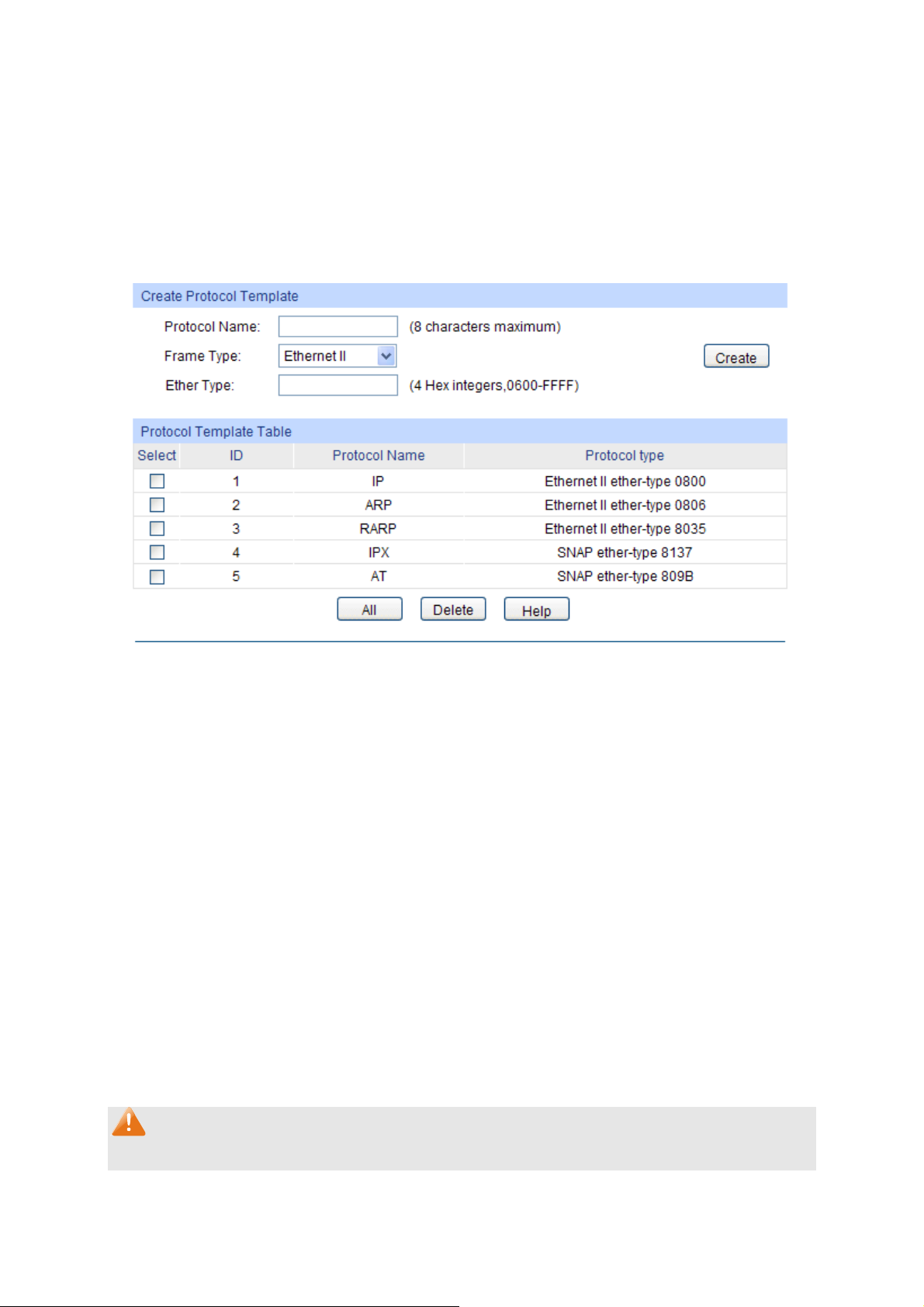
7.5.3 Protocol Template
The Protocol Template should be created before configuring the Protocol VLAN. By default, the
switch has defined the IP Template, ARP Template, RARP Template, etc. You can add more
Protocol Template on this page.
Choose the menu VLAN→Protocol VLAN→Protocol Template to load the following page.
Figure 7-11 Create and View Protocol Template
The following entries are displayed on this screen:
Create Protocol Template
Protocol Name: Give a name for the Protocol Template.
Frame Type: Select a Frame Type for the Protocol Template.
Ether Type: Enter the Ethernet protocol type field in the protocol template.
DSAP: Enter the DSAP field when selected LLC.
SSAP: Enter the SSAP field when selected LLC.
Protocol Template Table
Select: Select the desired entry. It is multi-optional.
ID Displays the Protocol Template ID.
Protocol Name: Displays the Protocol Name.
Protocol Type: Displays the Protocol type.
Note:
The Protocol Template bound to VLAN can not be deleted.
79
Page 91

Configuration Procedure:
Step Operation Description
1 Set the link type for port. Required. On the VLAN→802.1Q VLAN→Port Config page,
set the link type for the port basing on its connected device.
2 Create VLAN. Required. On the VLAN→802.1Q VLAN→VLAN Config
page, click the Create button to create a VLAN. Enter the
VLAN ID and the description for the VLAN. Meanwhile,
specify its member ports.
3 Create Protocol Template. Required. On the VLAN→Protocol VLAN→Protocol
Template page, create the Protocol Template before
configuring Protocol VLAN.
4 Create Protocol VLAN. Required. On the VLAN→Protocol VLAN→Protocol
Group page, select the protocol name and enter the VLAN
ID to create a Protocol VLAN. Meanwhile, enable protocol
VLAN for ports.
5 Modify/View VLAN. Optional. On the VLAN→Protocol VLAN→Protocol
Group Table page, click the Edit button to modify/view the
information of the corresponding VLAN.
6 Delete VLAN. Optional. On the VLAN→Protocol VLAN→Protocol
Group Table page, select the desired entry to delete the
corresponding VLAN by clicking the Delete button.
7.6 Application Example for Protocol VLAN
Network Requirements
Department A is connected to the company LAN via Port12 of switch A;
Department A has IP host and AppleTalk host;
IP host, in VLAN10, is served by IP server while AppleTalk host is served by AppleTalk server;
Switch B is connected to IP server and AppleTalk server.
80
Page 92

Network Diagram
Configuration Procedure
Configure switch A
Step Operation Description
5 Configure the
Link Type of the
ports
Required. On VLAN→802.1Q VLAN→Port Config page, configure the
link type of Port 11 and Port 13 as ACCESS, and configure the link type
of Port 12 as GENERAL.
6 Create VLAN10 Required. On VLAN→802.1Q VLAN→VLAN Config page, create a
VLAN with its VLAN ID as 10, owning Port 12 and Port 13, and
configure the egress rule of Port 12 as Untag.
7 Create VLAN20 Required. On VLAN→802.1Q VLAN→VLAN Config page, create a
VLAN with its VLAN ID as 20, owning Port 11 and Port 12, and
configure the egress rule of Port 12 as Untag.
Configure switch B
Step Operation Description
1 Configure the
Link Type of the
ports
Required. On VLAN→802.1Q VLAN→Port Config page, configure the
link type of Port 4 and Port 5 as ACCESS, and configure the link type of
Port 3 as GENERAL.
2 Create VLAN10 Required. On VLAN→802.1Q VLAN→VLAN Config page, create a
VLAN with its VLAN ID as 10, owning Port 3 and Port 4, and configure
the egress rule of Port 3 as Untag.
3 Create VLAN20 Required. On VLAN→802.1Q VLAN→VLAN Config page, create a
VLAN with its VLAN ID as 20, owning Port 3 and Port 5, and configure
the egress rule of Port 3 as Untag.
81
Page 93

Step Operation Description
4 Create Protocol
Tem pl at e
5 Create Protocol
VLAN 10
6 Create Protocol
VLAN 20
Required. On VLAN→Protocol VLAN→Protocol Template page,
configure the protocol template practically. E.g. the Ether Type of IP
network packets is 0800 and that of AppleTalk network packets is 809B.
On VLAN→Protocol VLAN→Protocol Group page, create protocol
VLAN 10 with Protocol as IP. Select and enable Port 3, Port 4 and Port
5 for Protocol VLAN feature.
On VLAN→Protocol VLAN→Protocol Group page, create protocol
VLAN 20 with Protocol as AppleTalk. Select and enable Port 3, Port 4
and Port 5 for Protocol VLAN feature.
7.7 VLAN VPN
With the increasing application of the Internet, the VPN (Virtual Private Network) technology is
developed and used to establish the private network through the operators’ backbone networks.
VLAN-VPN (Virtual Private Network) function, the implement of a simple and flexible Layer 2 VPN
technology, allows the packets with VLAN tags of private networks to be encapsulated with VLAN
tags of public networks at the network access terminal of the Internet Service Provider. And these
packets will be transmitted with double-tag across the public networks.
The VLAN-VPN function provides you with the following benefits:
(1) Provides simple Layer 2 VPN solutions for small-sized LANs or intranets.
(2) Saves public network VLAN ID resource.
(3) You can have VLAN IDs of your own, which is independent of public network VLAN IDs.
(4) When the network of the Internet Service Provider is upgraded, the user’s network with a
relative independence can still work normally without changing the current configurations.
In addition, the switch supports the feature to adjust the TPID Values of VLAN VPN Packets. TPID
(Tag Protocol Identifier) is a field of the VLAN tag. IEEE 802.1Q specifies the value of TPID to be
0x8100. This switch adopts the default value of TPID (0x8100) defined by the protocol. Other
manufacturers use other TPID values (such as 0x9100 or 0x9200) in the outer tags of VLAN-VPN
packets. To be compatible with devices coming from other manufacturers, this switch can adjust
the TPID values of VLAN-VPN packets globally. You can configure TPID values by yourself. When
a port receives a packet, this port will replace the TPID value in the outer VLAN tag of this packet
with the user-defined value and then send the packet again. Thus, the VLAN-VPN packets sent to
the public network can be recognized by devices of other manufacturers.
The position of the TPID field in an Ethernet packet is the same as the position of the protocol type
field in the packet without VLAN Tag. Thus, to avoid confusion happening when the switch
forwards or receives a packet, you must not configure the following protocol type values listed in
the following table as the TPID value.
Protocol type Valu e
ARP 0x0806
IP 0x0800
MPLS 0x8847/0x8848
IPX 0x8137
IS-IS 0x8000
82
Page 94
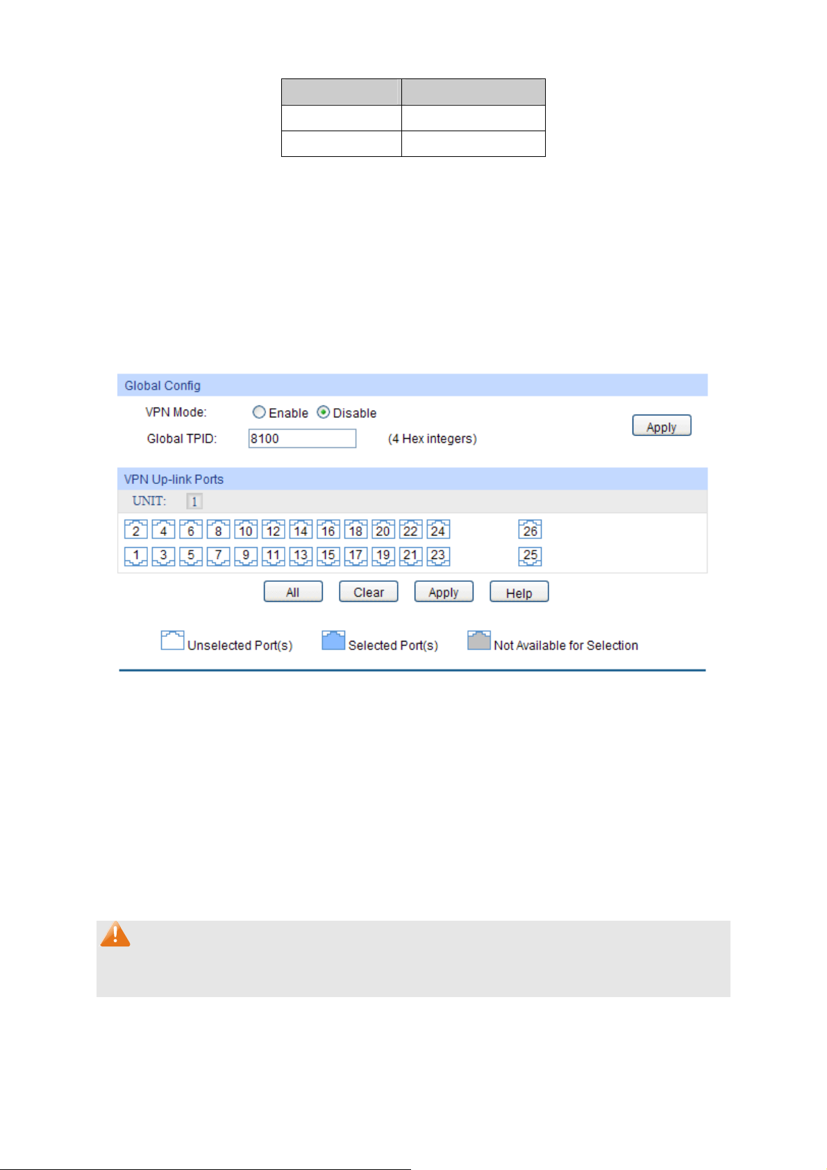
Protocol type Valu e
LACP 0x8809
802.1X 0x888E
Table 7-3 Values of Ethernet frame protocol type in common use
This VLAN VPN function is implemented on the VPN Config, VLAN Mapping and Port Enable
pages.
7.7.1 VPN Config
This page allows you to enable the VPN function, adjust the global TPID for VLAN-VPN packets
and enable the VPN up-link port. When VPN mode is enabled, the switch will add a tag to the
received tagged packet basing on the VLAN mapping entries.
Choose the menu VLAN→VLAN VPN→VPN Config to load the following page.
Figure 7-12 VPN Global Config
The following entries are displayed on this screen:
Global Config
VPN Mode: Allows you to Enable/Disable the VLAN-VPN function.
Global TPID: Enter the global TPID (Tag protocol identifier).
VPN Up-link Ports
Unit: Select the unit ID of the desired member in the stack.
VPN Up-link ports: Select the desired port as the VPN Up-link port.
Note:
If VPN mode is enabled, please create VLAN Mapping entries on the VLAN Mapping function
page.
7.7.2 Port Enable
On this page, you can enable the port for the VLAN Mapping function. Only the port is enabled,
can the configured VLAN Mapping function take effect.
83
Page 95
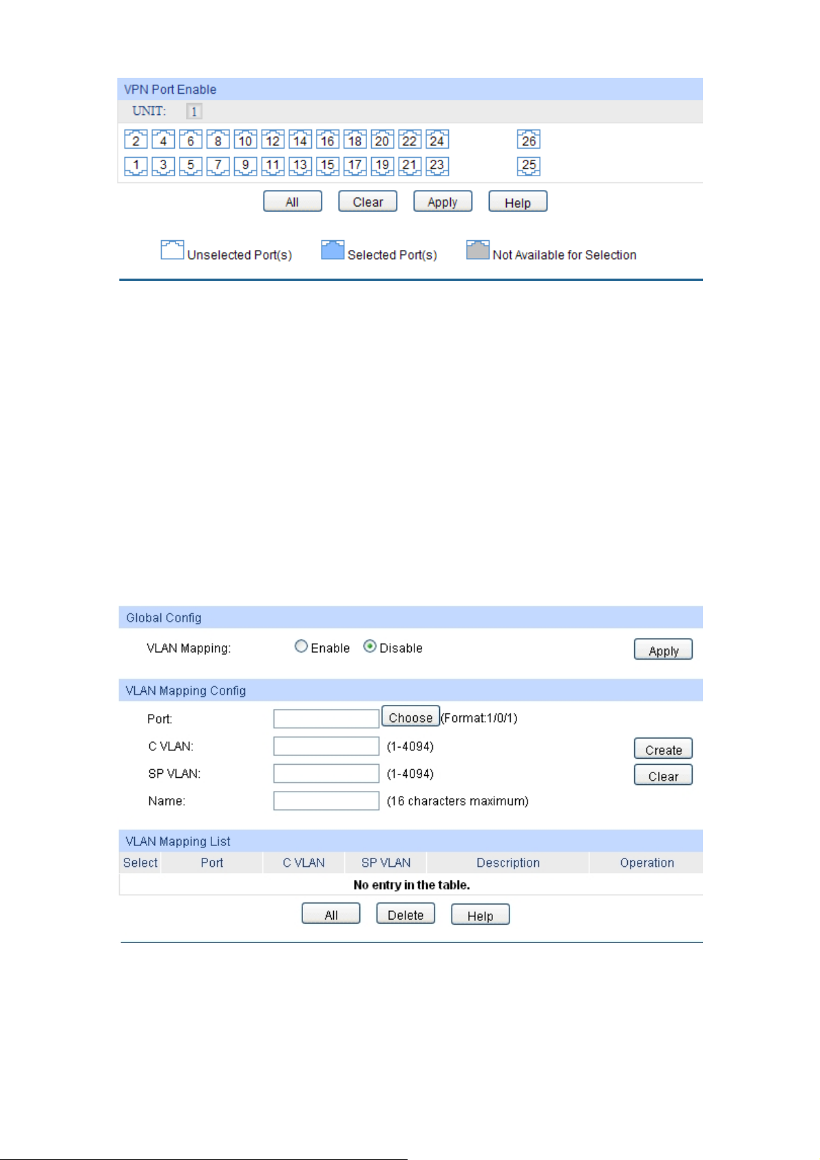
Figure 7-13 Enable Port for VLAN Mapping
VPN Port Enable
UNIT: Select the unit ID of the desired member in the stack.
Select your desired port for VLAN Mapping function. All the ports are disabled for VLAN Mapping
function by default.
7.7.3 VLAN Mapping
VLAN Mapping function allows the VLAN TAG of the packets to be replaced with the new VLAN
TAG according to the VLAN Mapping entries. And these packets can be forwarded in the new
VLAN. If VLAN VPN function is enabled, a received packet already carrying a VLAN tag will be
tagged basing on the VLAN Mapping entries and becomes a double-tagged packet to be
forwarded in the new VLAN.
Choose the menu VLAN→VLAN VPN→VLAN Mapping to load the following page.
Figure 7-14 Create VLAN Mapping Entry
The following entries are displayed on this screen:
Global Config
VLAN Mapping: Enable/Disable the VLAN mapping function.
84
Page 96

VLAN Mapping Config
Port: Select/Input the port number.
C VLAN: Enter the ID number of the Customer VLAN. C VLAN refers to the
VLAN to which the packet received by switch belongs.
SP VLAN: Enter the ID number of the Service Provider VLAN.
Name: Give a name to the VLAN Mapping entry or leave it blank.
VLAN Mapping List
Select: Select the desired entry to delete the corresponding VLAN
Mapping entry. It is multi-optional.
Operation: Click the Edit button to modify the settings of the entry.
Click Edit to display the following figure:
Figure 7-15 VLAN Mapping Entry Config
Modify the SP VLAN and name of the selected entry and click Edit to apply.
Note:
When VPN mode is globally enabled, VPN function takes effect on all ports. If VPN mode is
disabled, VLAN Mapping function can be enabled by selecting your desired port on this Port
Enable page.
Configuration Procedure of VLAN VPN Function:
Step Operation Description
1 Enable VPN mode. Required. On the VLAN→VLAN VPN→VPN Config page,
enable the VPN mode.
2 Configure the global TPID. Optional. On the VLAN→VLAN VPN→VPN Config page,
configure the global TPID basing on the devices connected
to the up-link port.
85
Page 97

Step Operation Description
3 Set the VPN up-link port. Required. On the VLAN→VLAN VPN→VPN Config page,
specify the desired port to be the VPN up-link port. It’s
required to set the port connected to the backbone
networks to be up-link port.
4 Create VLAN Mapping
entries.
5 Create SP (Service
Provider) VLAN.
Required. On the VLAN→VLAN VPN→VLAN Mapping
page, configure the VLAN Mapping entries basing on the
actual application.
Optional. On the VLAN→802.1Q VLAN page, create the
SP VLAN. For the steps of creating VLAN, please refer to
802.1Q VLAN
.
Configuration Procedure of VLAN Mapping Function:
Step Operation Description
1 Create VLAN Mapping
entries.
2 Enable VLAN Mapping
function for port.
3 Create SP (Service
Provider) VLAN
Required. On the VLAN→VLAN VPN→VLAN Mapping
page, configure the VLAN Mapping entries basing on the
actual application.
Required. On the VLAN→VLAN VPN→Port Enable page,
enable VLAN Mapping function for the ports.
Optional. On the VLAN→802.1Q VLAN page, create the
SP VLAN. For the steps of creating VLAN, please refer to
802.1Q VLAN
.
7.8 GVRP
GVRP (GARP VLAN Registration Protocol) is an implementation of GARP (generic attribute
registration protocol). GVRP allows the switch to automatically add or remove the VLANs via the
dynamic VLAN registration information and propagate the local VLAN registration information to
other switches, without having to individually configure each VLAN.
GARP
GARP provides the mechanism to assist the switch members in LAN to deliver, propagate and
register the information among the members. GARP itself does not work as the entity among the
devices. The application complied with GARP is called GARP implementation, and GVRP is the
implementation of GARP. When GARP is implemented on a port of device, the port is called
GARP entity.
The information exchange between GARP entities is completed by messages. GARP defines the
messages into three types: Join, Leave and LeaveAll.
Join Message: When a GARP entity expects other switches to register certain attribute
information of its own, it sends out a Join message. And when receiving the Join message
from the other entity or configuring some attributes statically, the device also sends out a Join
message in order to be registered by the other GARP entities.
Leave Message: When a GARP entity expects other switches to deregister certain attribute
information of its own, it sends out a Leave message. And when receiving the Leave message
from the other entity or deregistering some attributes statically, the device also sends out a
Leave message.
86
Page 98

LeaveAll Message: Once a GARP entity starts up, it starts the LeaveAll timer. After the timer
times out, the GARP entity sends out a LeaveAll message. LeaveAll message is to deregister
all the attribute information so as to enable the other GARP entities to re-register attribute
information of their own.
Through message exchange, all the attribute information to be registered can be propagated to all
the switches in the same switched network.
The interval of GARP messages is controlled by timers. GARP defines the following timers:
Hold Timer: When a GARP entity receives a piece of registration information, it does not send
out a Join message immediately. Instead, to save the bandwidth resources, it starts the Hold
timer, puts all registration information it receives before the timer times out into one Join
message and sends out the message after the timer times out.
Join Timer: To transmit the Join messages reliably to other entities, a GARP entity sends
each Join message two times. The Join timer is used to define the interval between the two
sending operations of each Join message.
Leave Timer: When a GARP entity expects to deregister a piece of attribute information, it
sends out a Leave message. Any GARP entity receiving this message starts its Leave timer,
and deregisters the attribute information if it does not receives a Join message again before
the timer times out.
LeaveAll Timer: Once a GARP entity starts up, it starts the LeaveAll timer, and sends out a
LeaveAll message after the timer times out, so that other GARP entities can re-register all the
attribute information on this entity. After that, the entity restarts the LeaveAll timer to begin a
new cycle.
GVRP
GVRP, as an implementation of GARP, maintains dynamic VLAN registration information and
propagates the information to other switches by adopting the same mechanism of GARP.
After the GVRP feature is enabled on a switch, the switch receives the VLAN registration
information from other switches to dynamically update the local VLAN registration information,
including VLAN members, ports through which the VLAN members can be reached, and so on.
The switch also propagates the local VLAN registration information to other switches so that all the
switching devices in the same switched network can have the same VLAN information. The VLAN
registration information includes not only the static registration information configured locally, but
also the dynamic registration information, which is received from other switches.
In this switch, only the port with TRUNK link type can be set as the GVRP application entity to
maintain the VLAN registration information. GVRP has the following three port registration modes:
Normal, Fixed, and Forbidden.
Normal: In this mode, a port can dynamically register/deregister a VLAN and propagate the
dynamic/static VLAN information.
Fixed: In this mode, a port cannot register/deregister a VLAN dynamically. It only propagates
static VLAN information. That is, the port in Fixed mode only permits the packets of its static
VLAN to pass.
87
Page 99

Forbidden: In this mode, a port cann
ot register/deregister VLANs. It only propagates VLAN 1
information. That is, the port in Forbidden mode only permits the packets of the default VLAN
(namely VLAN 1) to pass.
Choose the menu VLAN→GVRP→GVRP Config to load the following page.
Figure 7-16 GVRP Config
Note:
If the GVRP feature is enabled for a member port of LAG, please ensure all the member ports of
this LAG are set to be in the same status and registration mode.
The following entries are displayed on this screen:
Global Config
GVRP: Allows you to Enable/Disable the GVRP function.
Port Config
Unit: Select the unit ID of the desired member in the stack.
Select: Select the desired port for configuration. It is multi-optional.
Port: Displays the port number.
Status: Enable/Disable the GVRP feature for the port. The port type should
be set to TRUNK before enabling the GVRP feature.
88
Page 100

Registration
Mode:
LeaveAll Timer: Once the LeaveAll Timer is set, the port with GVRP enabled can send
Join Timer: To guarantee the transmission of the Join messages, a GARP port
Leave Timer: Once the Leave Timer is set, the GARP port receiving a Leave
Select the R
Normal: In this mode, a port can dynamically register/deregister
a VLAN and propagate the dynamic/static VLAN information.
Fixed: In this mode, a port cannot register/deregister a VLAN
dynamically. It only propagates static VLAN information.
Forbidden: In this mode, a port cannot register/deregister
VLANs. It only propagates VLAN 1 information.
a LeaveAll message after the timer times out, so that other GARP
ports can re-register all the attribute information. After that, the
LeaveAll timer will start to begin a new cycle. The LeaveAll Timer
ranges from 1000 to 30000 centiseconds.
sends each Join message two times. The Join Timer is used to define
the interval between the two sending operations of each Join
message. The Join Timer ranges from 20 to 1000 centiseconds.
message will start its Leave timer, and deregister the attribute
information if it does not receive a Join message again before the
timer times out. The Leave Timer ranges from 60 to 3000
centiseconds.
egistration Mode for the port.
LAG: Displays the LAG to which the port belongs.
Note:
LeaveAll Timer >= 10* Leave Timer, Leave Timer >= 2*Join Timer
Configuration Procedure:
Step Operation Description
1 Set the link type for port. Required. On the VLAN→802.1Q VLAN→Port Config
page, set the link type of the port to be TRUNK.
2 Enable GVRP function. Required. On the VLAN→GVRP page, enable GVRP
function.
3 Configure the registration
mode and the timers for the
port.
Required. On the VLAN→GVRP page, configure the
parameters of ports basing on actual applications.
7.9 Private VLAN
Private VLANs, designed to save VLAN resources of uplink devices and decrease broadcast, are
sets of VLAN pairs that share a common primary identifier. To guarantee user information security,
the ease with which to manage and account traffic for service providers, in campus network,
service providers usually require that each individual user is Layer-2 separated. VLAN feature can
solve this problem. However, as stipulated by IEEE 802.1Q protocol, a device can only support up
to 4094 VLANs. If a service provider assigns one VLAN per user, the VLANs will be far from
enough; as a result, the number of users this service provider can support is limited.
89
 Loading...