

Page 1

Business Networking Solution
Installation Guide
JetStream 24-Port Gigabit Stackable Smart Switch
with 4 10GE SFP+ Slots
T1700G-28TQ
Page 2

Page 3
About this Installation Guide
This Installation Guide describes the hardware characteristics, installation methods and the
points that should be attended to during the installation. This Installation Guide is structured as
follows:
Chapter 1 Introduction.
This chapter describes the external components of the switch.
Chapter 2 Installation.
This chapter illustrates how to install the switch.
Chapter 3 Lightning Protection.
This chapter illustrates how to prevent lightning damage.
Chapter 4 Connection.
This chapter illustrates how to do the physical connection of the switch.
Chapter 5 Configuration.
This chapter instructs you to configure the switch via Web Interface and CLI commands.
Appendix A Troubleshooting.
Appendix B Specifications.
Audience
This Installation Guide is for:
Network Engineer Network Administrator
Conventions
• The figures in Chapter 2 to Chapter 4 are for demonstration purposes only. Your switch may differ
in appearance from that depicted.
• This Guide uses the specific formats to highlight special messages. The following table lists the
notice icons that are used throughout this guide.
Remind to be careful. A caution indicates a potential which may result in device damage.
Remind to take notice. The note contains the helpful information for a better use of the
product.
Related Document
The User Guide and CLI Reference Guide of the product are provided on the resource CD. To
obtain the latest product information, please visit the official website: http://www.tp-link.com
IAbout this Installation Guide
Page 4

JetStream 24-Port Gigabit Stackable Smart Switch with 4 10GE SFP+ Slots
Contents
Chapter 1 Introduction ——————————— 01
1.1 Product Overview ...........................................................01
1.2 Appearance .......................................................................01
Chapter 2 Installation ——————————— 04
2.1 Package Contents ..........................................................04
2.2 Safety Precautions .........................................................04
2.3 Installation Tools ..............................................................06
2.4 Product Installation ........................................................07
2.5 Stacking Using SFP+ Port ............................................08
Chapter 3 Lightning Protection ——————— 10
3.1 Cabling Reasonably........................................................10
3.2 Connect to Ground .........................................................12
Chapter 4 Connection ——————————— 16
4.1 Ethernet Port ....................................................................16
4.2 SFP+ Port ...........................................................................16
4.3 Verify Installation .............................................................16
4.4 Power On ............................................................................17
4.5 Initialization ........................................................................17
II
Chapter 5 Conguration —————————— 18
5.1 Congure the Switch via GUI ......................................18
5.2 Congure the Switch Using CLI .................................19
Appendix A Troubleshooting ———————— 21
Appendix B Specications ————————— 22
Contents
Page 5
JetStream 24-Port Gigabit Stackable Smart Switch with 4 10GE SFP+ Slots
Chapter 1 Introduction
1.1 Product Overview
TP-LINK Gigabit Smart Switch, designed for workgroups and departments, provides
wire-speed performance and abundant L2 management features. It provides a variety
of service features and multiple powerful functions with high security.
The EIA-standardized framework and smar t configuration capacity can provide flexible
solutions for a variable scale of networks. QoS and IGMP snooping/filtering optimize
voice and video application. Link aggregation increases aggregated bandwidth,
optimizing the transport of business critical data. SNMP, RMON, WEB and CLI Login bring abundant management policies. TP-LINK Gigabit Smart Switch integrates
multiple functions with excellent performance, and is friendly to manage, which can
fully meet the need of the users demanding higher networking per formance.
T1700G-28TQ also supports stacking of up to 6 units, thus providing flexible scalabilit y
and protective redundancy for your networks.
1.2 Appearance
■
Front Panel
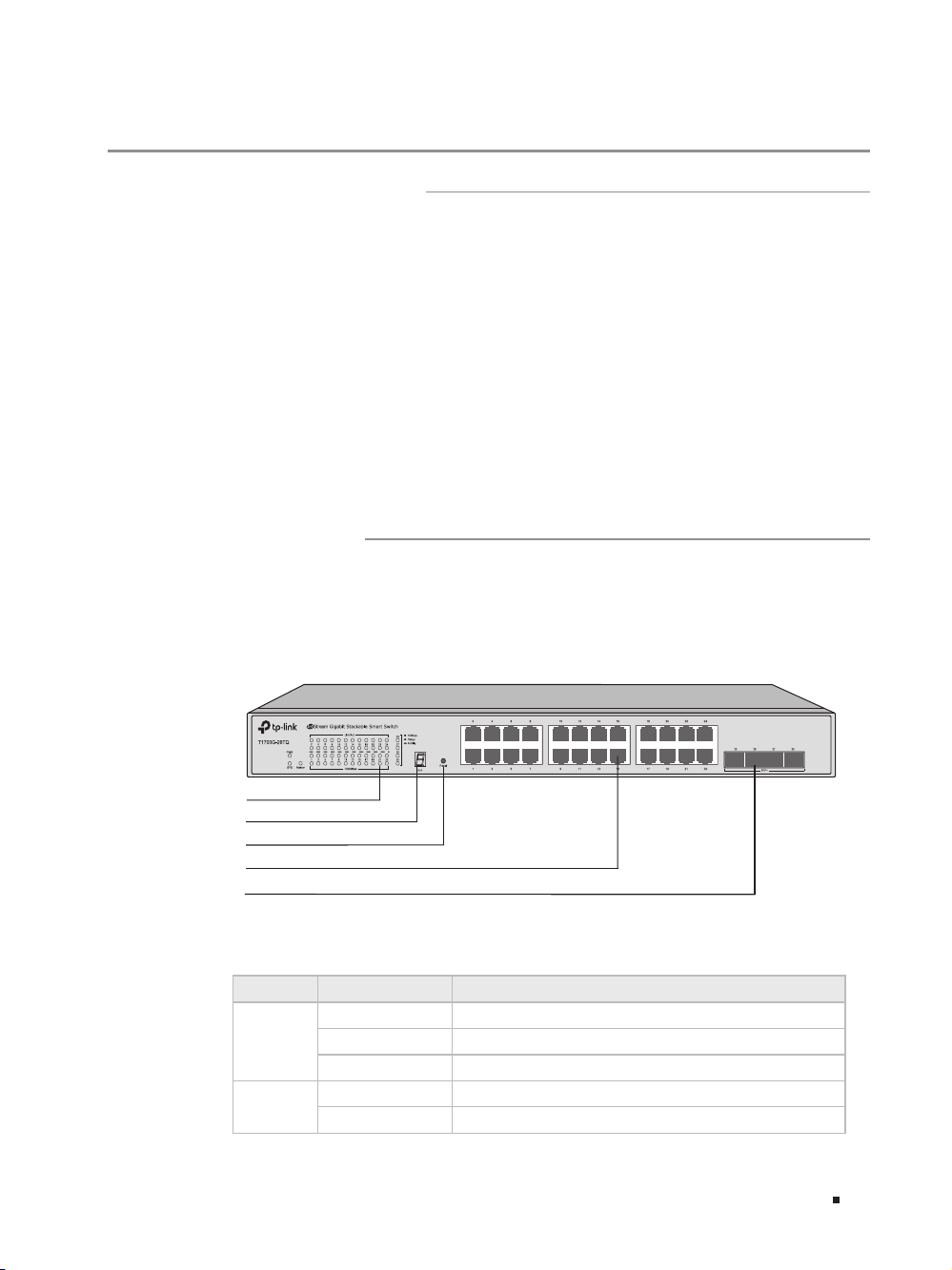
The front panel of T1700G-28TQ is shown as the following figure.
Figu re 1-1 Front Panel of T1700G-28TQ
LEDs
Unit ID LED
Reset
10/100/1000Mbps RJ45 Port
SFP+ Port
LEDs
LED Status Indication
On The switch is powered on
PWR
SYS
Off The switch is powered of f
Flashing
Flashing The switch is working normally
On/Off The switch is working abnormally
Power supply is abnormal
01Introduction
Page 6

JetStream 24-Port Gigabit Stackable Smart Switch with 4 10GE SFP+ Slots
LED Status Indication
The switch works as master in the stack system, or
does not join any stack system
There is a device connected to the corresponding
port but no activity
Data is being transmitted or received
A 1000Mbps device is connected to the corresponding
port
A 10/100Mbps device or no device is connected to the
corresponding port
A 10Gbps device is connected to the corresponding port,
but no activity
Data is being transmitted or received
A 1000Mbps device is connected to the corresponding
port, but no activity
Data is being transmitted or received
No device is connected to the corresponding port
Master
Link/Act
1000Mbps
25-28
On
Off The switch works as stack member in the stack system
On
Flashing
Off No device is connected to the corresponding port
On
Off
Green
Yellow
Off
On
Flashing
On
Flashing
Unit ID LED
Designed to display the stack Unit ID of the switch. For the switch that does not join
any stack system, it displays its default Unit ID. To modify the default unit number,
please logon to the GUI of the switch and go to Stack→Stack Management→Stack
Config page and configure the New Unit ID. The new Unit ID will take effect after you
reboot the switch.
Reset
Press this button for 5 seconds or above to reset the software setting back to
factory default settings.
10/100/1000Mbps RJ45 Port
Designed to connect to the device with a bandwidth of 10Mbps, 100Mbps or
1000Mbps. Each has a corresponding Link/Act LED and a 1000Mbps LED.
SFP+ Port
Port 25-28, designed to install the 1Gbps SFP transceiver, 10Gbps SFP+ transceiver
or SFP+ cable.
Port Feature
Model 10/10 0/1000Mbps RJ45 Port SFP+ Port
T1700G-28TQ 24 4
02 Introduction
Page 7
JetStream 24-Port Gigabit Stackable Smart Switch with 4 10GE SFP+ Slots
■
Rear Panel
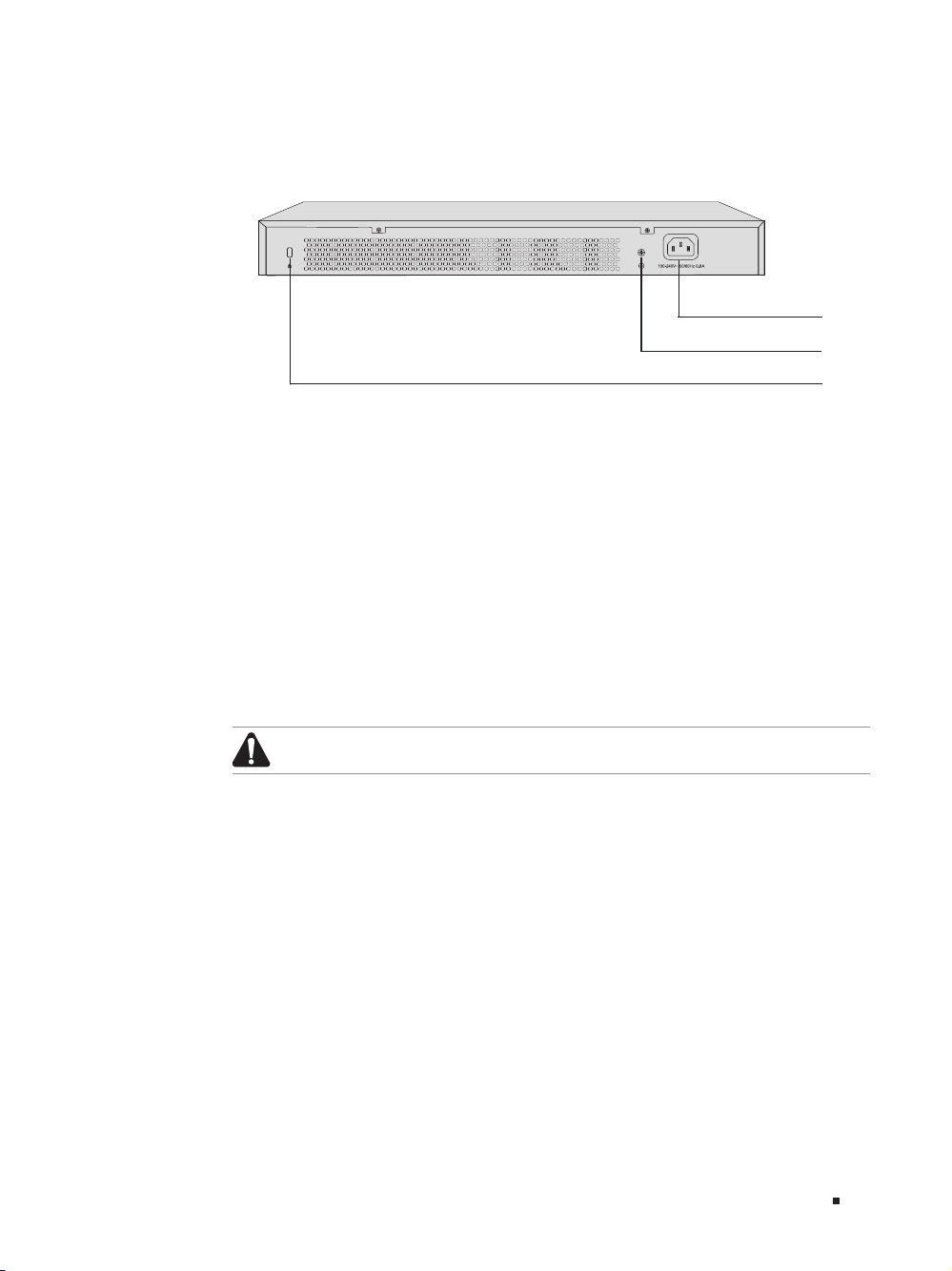
The rear panel of T1700G-28TQ is shown as the following figure.
Figu re 1-2 Rear Panel of T1700G -28TQ
Power Socket
Grounding Terminal
Kensi ngton Securit y Slot
Kensington Security Slot
Secure the lock (not provided) into the security slot to prevent the device from being
stolen.
Grounding Terminal
The switch already comes with lightning protection mechanism. You can also ground
the switch through the PE (Protecting Earth) cable of AC cord or with Ground Cable.
For detailed information, please refer to Chapter 3 Lightning Protection.
Power Socket
Connect the female connector of the power cord here, and the male connector to
the AC (Alternating Current) power outlet. Please make sure the voltage of the power
supply meets the requirement of the input voltage.
Caution:
Please use the provided power cord.
03Introduction
Page 8
JetStream 24-Port Gigabit Stackable Smart Switch with 4 10GE SFP+ Slots
Chapter 2 Installation
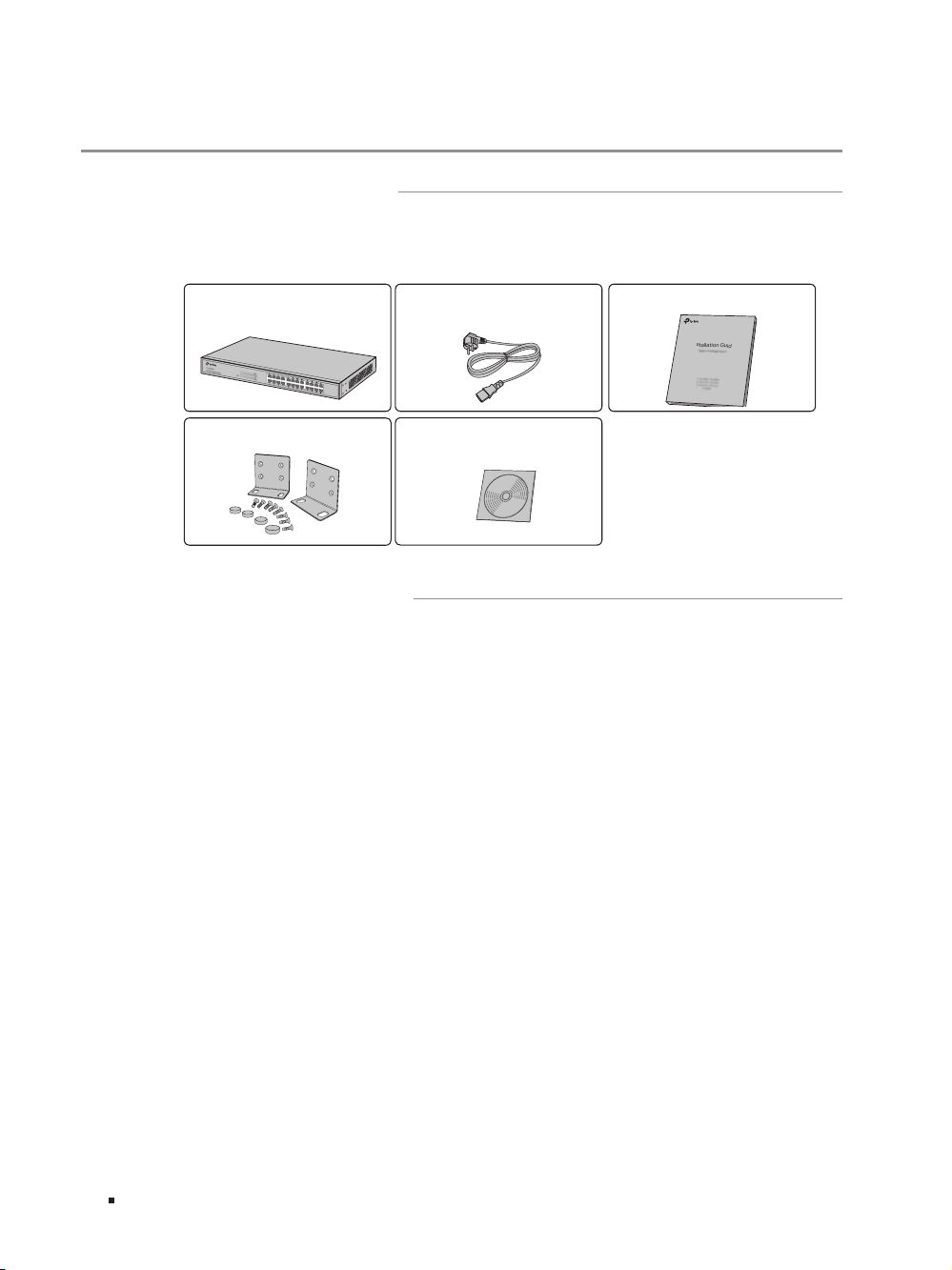
2.1 Package Contents
Make sure that the package contains the following items. If any of the listed items is
damaged or missing, please contact your distributor.
One Switch
Two mounting brackets, eight
One Power Cord
One Resource CD
This Installation Guide
Business Networking Solution
Installation Guide
screws and four feet
2.2 Safety Precautions
To avoid any device damage and bodily injury caused by improper use, please observe
the following rules.
■
Safety Precautions
■
Keep the power off during the installation.
■
Wear an ESD-preventive wrist strap, and make sure that the wrist strap has a good skin
contact and is well grounded.
■
Use only the power cord provided with the switch.
■
Make sure that the supply voltage matches the specifications indicated on the rear
panel of the switch.
■
Ensure the vent hole is well ventilated and unblocked.
■
Do not open or remove the cover of the switch.
■
Before cleaning the device, cut off the power supply. Do not clean it by the waterish
cloth, and never use any other liquid cleaning method.
04 Installation
Page 9
JetStream 24-Port Gigabit Stackable Smart Switch with 4 10GE SFP+ Slots
40℃
■
Site Requirements
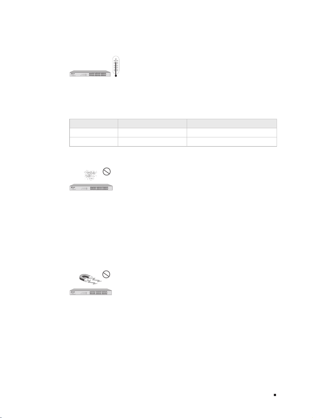
Temperature/Humidity
0℃
Please keep a proper temperature and humidity in the equipment room. Too high/low
humidity may lead to bad insulation, electricity leakage, mechanical propert y changes
and corrosions. Too high temperature may accelerate aging of the insulation materials
and can thus significantly shorten the service life of the device. For normal temperature
and humidity of the device, please check the following table.
Environment Temperature Humidity
Operating 0℃ to 40
Storage -40℃ to 70
℃
℃
10% to 90%RH Non-condensing
5% to 90%RH Non-condensing
Clearness
The dust accumulated on the switch can be absorbed by static electricity and result
in poor contact of metal contact points. Some measures have been taken for the
device to prevent static electricity, but too strong static electricity can cause deadly
damage to the electronic elements on the internal circuit board. To avoid the effect of
static electricity on the operation of the Switch, please attach much importance to the
following items:
■
Dust the device regularly, and keep the indoor air clean.
■
Keep the device well grounded and ensure static electricity has been transferred.
Electromagnetic Interference
Electronic elements including capacitance and inductance on the device can be
affected by external interferences, such as conducted emission by capacitance
coupling, inductance coupling, and impedance coupling. To decrease the interferences,
please make sure to take the following measures:
■
Use the power supply that can effectively filter interference from the power grid.
■
Keep the device far from high-frequency, strong-current devices, such as radio
transmitting station.
■
Use electromagnetic shielding when necessary.
05Installation
Page 10

JetStream 24-Port Gigabit Stackable Smart Switch with 4 10GE SFP+ Slots
Lightening Protection
Extremely high voltage currents can be produced instantly when lightning occurs and
the air in the electric discharge path can be instantly heated up to 20,000℃. As this
instant current is strong enough to damage electronic devices, more effective lightning
protection measures should be taken.
■
Ensure the rack and device are well earthed.
■
Make sure the power socket has a good contact with the ground.
■
Keep a reasonable cabling system and avoid induced lightning.
■
Use the signal SPD (Surge Protective Device) when wiring outdoor.
Note:
For detailed lightning protection measures, please refer to Chapter 3 Lightning
Protection.
Installation Site
When installing the device on a rack or a flat workbench, please note the following
items:
■
The rack or workbench is flat and stable, and sturdy enough to support the weight of
5.5kg at least.
■
The rack or workbench has a good ventilation system. The equipment room is well
ventilated.
■
The rack is well grounded. Keep the power socket less than 1.5 meters away from the
device.
2.3 Installation Tools
■
Phillips screwdriver
■
ESD-preventive wrist wrap
■
Cables
06 Installation
Note:
These tools are not provided with our product. If needed, please self purchase
them.
Page 11

JetStream 24-Port Gigabit Stackable Smart Switch with 4 10GE SFP+ Slots
2.4 Product Installation
■
Desktop Installation
To install the device on the desktop, please follow the steps:
1. Set the device on a flat surface strong enough to support the entire weight of the
device with all fittings.
2. Remove the adhesive backing papers from the rubber feet.
3. Turnover the device and attach the supplied rubber feet to the recessed areas on
the bottom at each corner of the device.
Figu re 2-1 Desktop Installation
Feet
Bottom of the Device
Notch
■
Rack Installation
To install the device in an EIA standard-sized, 19-inch rack, follow the instructions
described below:
1. Check the grounding and stability of the rack.
2. Secure the supplied rack-mounting brackets to each side of the device with supplied
screws, as illustrated in the following figure.
Figu re 2-2 Bracket Installation
Rack-mounting Bracket
Screw
07Installation
Page 12

JetStream 24-Port Gigabit Stackable Smart Switch with 4 10GE SFP+ Slots
3. After the brackets are attached to the device, use suitable screws (not provided) to
secure the brackets to the rack, as illustrated in the following figure.
Figu re 2-3 Rack Installation
Caution:
■
Please set 5 to 10cm gaps around the device for air circulation.
■
Please avoid any heavy thing placed on the device.
■
Please mount devices in sequence from the bottom to top of the rack and ensure
a certain clearance between devices for the purpose of heat dissipation.
2.5 Stacking Using SFP+ Port
Rack
You can connect up to 6 switches to form a stack with a single management IP address.
Follow the steps below to connect the switches and configure the stack ports, then the
switches will automatically elect a master unit and establish a stack. Once the stack
is established, you can use any port of any switch in the stack to manage the stack
system.
Any SFP+ ports (Port 25-28) on the front panel can be used for stacking. Port 25-26
belong to Stack Port Group 0 and Port 27-28 belong to Stack Port Group 1. Since stack
capability cannot be enabled in the two groups simultaneously, you can enable stack
feature in either Group 0 or Group 1.
Here is an example of a recommended configuration that uses three rack-mounted
switches to form a full-ring stack.
Conguration and Connection
1. Log on to the GUI of each switch, go to Stack→Stack Management→Stack Cong
page to enable the Stack Capability of port 25 and 26 (port 1/0/25 and 1/0/26 on the
GUI). Remember to click Apply after the configuration.
2. Power off the switches, and then use the 10G SFP+ cable (TXC432-CU1M/TXC432CU3M of TP-LINK for example) to connect each switch to the next in a cascade.
Finally, connect the last switch in the stack to the first switch, thus forming a ring
topology as Figure 2-4 shows. The ring topology system provides redundancy and
resiliency to the stack.
08 Installation
Page 13

JetStream 24-Port Gigabit Stackable Smart Switch with 4 10GE SFP+ Slots
25 26
SFP+
27 28
Figu re 2-4 Stac king Using SF P+ Port
SFP+ cable
Power On Sequence of the Stack Switches
Since the sequence in which the switches are first powered on might affect the switch
that becomes the stack master, please consider the following guidelines before
powering on the switches in the stack:
1. If you want a particular switch to become the stack master, power on this switch
first. After 1 minute, power on the other switches in the stack. That earliest startup
switch will remain the stack master until the next master re-election.
2. If you have no preference as to which switch becomes the stack master, power on all
the switches in the stack within 1 minute. The switches will participate in a election
to select a master. The Master LED of the selected switch will be on. The switches
powered on after 1 minutes don' t participate in the election, and they will become
member switches.
3. You can access to any member of the stack via Web/SSH/Telnet connection, thus to
manage all the switches in the stack.
For more information about stack topology and master election, please refer to "Stack"
chapter in the User Guide on the Resource CD.
Caution:
In the process of using TP-LINK SFP+ Cables, please never bend them into a
radius of 45mm (1.77 inch) or less, because it may permanently damage the SFP+
Cables.
09Installation
Page 14

JetStream 24-Port Gigabit Stackable Smart Switch with 4 10GE SFP+ Slots
Chapter 3 Lightning Protection
3.1 Cabling Reasonably
In the actual network environment, you may need cable outdoors and indoors, and
the requirements for cabling outdoors and indoors are different. A reasonable cabling
system can decrease the damage of induced lightning to devices.
Note:
It's not recommended using Ethernet cables outdoors. When cabling outdoors,
please use a signal lightning arrester.
■
Requirements for Cabling Outdoors
■
Aerial cabling without safeguard is not allowed.
■
It’s not allowed cabling down the building to connect network devices in different
floors.
■
Outdoor cables should be buried and paved to the indoor through basement. A piece of
steel wire should be paved underground along the pipe and connected to the lightning
protection terminal of the building for shielding. Before connecting the cable to the
device, install a signal lightning arrester on the corresponding port.
■
When an aerial cable is set up, the cable should be through a metal pipe (15m long
at least) before coming into the building. The two ends of this metal pipe should be
grounded. Before connecting the cable to the device, install a signal lightning arrester
on the corresponding port.
■
It’s not necessary to pave STP cables through pipes. The shielded layer of STP cable
should be well grounded. Before connecting the cable to the device, install a signal
lightning arrester on the corresponding port.
10 Lightning Protection
Page 15

JetStream 24-Port Gigabit Stackable Smart Switch with 4 10GE SFP+ Slots
■
Requirements for Cabling Indoors
When cabling indoors, keep a certain distance away from the devices that may cause
high-frequency interferences, such as down-conductor cable, powerline, power
transformer and electromotor.
■
The main cable should be paved in the metal raceway of the access shaft. When
cabling, keep the loop area formed by the cable itself as small as possible.
■
Requirements for the distance between Ethernet cable and other pipelines are shown
in the table.
Ethernet Cable
Other Pipelines
Min Parallel Net Length
L (mm)
Min Parallel-overlapping
Net Height H (mm)
Down-conductor 1000 300
PE 50 20
Service pipe 150 20
Compressed air pipe 150 20
Thermal pipe (not wrapped) 500 500
Thermal pipe (wrapped) 300 300
Gas pipe 300 20
The two diagrams below demonstrate parallel net length and parallel-overlapping
net height.
Note:
The above minimum net length/height is required when metal raceway is not
used. If any requirements cannot be met, you can add a steel tube or metal
raceway for shielding.
■
Requirements for the distance between Ethernet cable and high-power electric devices
are in following tables.
Cable Pave Way
Min Parallel
Length (mm)
Parallel cabling 130
<2kVA
powerline
One is in the grounded metal raceway or metal pipe 70
The both are in the grounded metal raceway or
metal pipe
10
11Lightning Protection
Page 16

JetStream 24-Port Gigabit Stackable Smart Switch with 4 10GE SFP+ Slots
Cable Pave Way
Parallel cabling 300
2 to 5kVA
powerline
>5kVA
powerline
Device Min Distance (m)
Switch case 1.00
Transformer room 2.00
Elevator tower 2.00
Air-conditioner room 2.00
One is in the grounded metal raceway or metal pipe 150
The both are in the grounded metal raceway or
metal pipe
Parallel cabling 600
One is in the grounded metal raceway or metal pipe 300
The both are in the grounded metal raceway or
metal pipe
Min Parallel
Length (mm)
80
150
3.2 Connect to Ground
Connecting the device to ground is to quickly release the lightning over-voltage and
over-current of the device, which is also a necessar y measure to protect the body from
electric shock.
In different environments, the device may be grounded differently. The following
will instruct you to connect the device to the ground in two ways, connecting to the
grounding bar or connecting to the ground via the power cord. Please connect the
device to ground in the optimum way according to your specific operation environment.
Note: For the device without grounding terminal, please refer to the first way
Connecting to the Ground via the Power Supply only.
■
Connecting to the Ground via the Power Supply
If the device is installed in the normal environment, the device can be grounded via the
PE (Protecting Earth) cable of the AC power supply as shown in the following figure.
12 Lightning Protection
Page 17

JetStream 24-Port Gigabit Stackable Smart Switch with 4 10GE SFP+ Slots
Switch (Rear Panel)
AC Power Cord (with PE cable)
Ground Cable
Grounding Bar
Figu re 3-1 Connecting to the Ground
Note:
■
The figure is to illustrate the application and principle. The power plug you get from
the package and the socket in your situation will comply with the regulation in your
country, so they may differ from the figure above.
■
If you intend to connect the device to the ground via the PE (Protecting Earth)
cable of AC power cord, please make sure the PE (Protecting Earth) cable in the
electrical outlet is well grounded in advance.
■
Connecting to the Ground via the Grounding Terminal
Use the grounding bar
If the device is installed in the Equipment Room, where a grounding bar is available, you
are recommended to connect the device to the grounding bar as shown in the following
figure.
Figu re 3-2 Connecting to the Grounding Bar
Switch (Rear Panel)
Grounding Terminal
Note:
The grounding bar and the ground cable are not provided with our product. If
needed, please self purchase them.
13Lightning Protection
Page 18

JetStream 24-Port Gigabit Stackable Smart Switch with 4 10GE SFP+ Slots
Grounding Bar Ground Cable
Equipotential Bonding
Equipotential Bonding is the practice of intentionally electrically connecting all earthed
systems to the same grounding grid or connecting the grounding grids of all the
earthed systems together through the ground or overground metal so as to create
an earthed equipotential zone. When lightning occurs, the high voltage produced by
lightning current in all systems will meanwhile exist in their ground cables, and thus all
ground cables have the same electrical potential and basically eliminate the electric
strikes between the systems.
The figure below illustrates how to practice equipotential bonding in a net work.
Figure 3-3 Equipotential Bonding
When equipotential bonding, please note that the cable should be copper wrapped
Kelly with its area being 6mm2 at least. The shorter cable the better, and use a
grounding bar to establish an equipotential bonding point.
Note:
The equipotential bonding cable and ground cable are not provided with our
product. If needed, please self purchase it.
Use Lightning Arrester
Power lightning arrester and signal lightning arrester are used for lighting protection.
Power lightning arrester is used for limiting the voltage surge due to a lightning. If an
outdoor AC power cord should be directly connected to the device, please use a power
lightning arrester.
14 Lightning Protection
Grounding Terminal Equipotential Bonding Cable
Page 19

JetStream 24-Port Gigabit Stackable Smart Switch with 4 10GE SFP+ Slots
Note:
Power lightning arrester is not provided with our product. If needed, please self
purchase it.
Signal lightning arrester is used to protect RJ45 ports of the device from lightning.
When cabling outdoors, please install a signal lightning arrester before connecting the
cable to the device.
When purchasing or using a signal lightning arrester, please observe the following
rules:
■
The port rate of the signal lightning arrester should match the rate of the desired port
on the device. If it is not matched, this signal lighting arrester will not work. Purchase a
standard lightning arrester.
■
Install signal lightning arrester near the protected device and connect it to the ground
via a shorter ground cable.
Figure 3-4 Equipotential Bonding
Ethernet CableEquipotential Bonding CableGrounding Terminal
Signal Lightning Arrester Device
Note:
Signal lightning arrester is not provided with our product. If needed, please self
purchase it.
15Lightning Protection
Page 20

JetStream 24-Port Gigabit Stackable Smart Switch with 4 10GE SFP+ Slots
Chapter 4 Connection
4.1 Ethernet Port
Connect a Ethernet port of the switch to the computer by RJ45 cable as the following
figure shows.
Figu re 4-1 Conn ecting th e RJ45 Port
RJ45 Port
4.2 SFP+ Port
Connect an SFP/SFP+ transceiver or an SFP+ cable to the SFP+ port. Make sure the
SFP+ module minimum bend radius is met when using the SFP+ cable.
The SFP+ ports support 10G connection by default. If you are using a gigabit SFP
module, please configure the speed of the corresponding SFP+ port as 1000M.
Figu re 4-2 I nserti ng the SFP+ Mo dule
SFP+ Port
SFP+ Transceiver
RJ45 Cable
4.3 Verify Installation
After completing the installation, please verify the following items:
■
There are 5 to 10cm of clearance around the sides of the device for ventilation and the
air flow is adequate.
■
The voltage of the power supply meets the requirement of the input voltage of the device.
16 Connection
Page 21

JetStream 24-Port Gigabit Stackable Smart Switch with 4 10GE SFP+ Slots
■
The power socket, device and rack are well grounded.
■
The device is correctly connected to other network devices.
4.4 Power On
Plug in the negative connector of the provided power cord into the power socket of the
device, and the positive connector into a power outlet as the following figure shows.
Figu re 4-3 C onnecti ng to Power Sup ply
2
1
Note:
The gure is to illustrate the application and principle. The power plug you get
from the package and the socket in your situation will comply with the regulation
in your countr y, so they may dier from the gure above.
4.5 Initialization
After the device is powered on, it begins the Power-On Self-Test. A series of tests
run automatically to ensure the device functions properly. During this time, its LED
indicators will respond in the following order:
1. The PWR LED lights on all the time. The SYS LED and the LED indicators of all the
ports keep off.
2. After over one minute, the LED indicators of all the ports will flash momentarily and
then turn off.
3. A few seconds later, the SYS LED indicator will flash, which represents a successful
initialization.
17Connection
Page 22

JetStream 24-Port Gigabit Stackable Smart Switch with 4 10GE SFP+ Slots
Chapter 5 Configuration
5.1 Configure the Switch via GUI
1. To access the GUI of the switch, open a web browser and type the default
management address http://192.168.0.1 in the address field of the browser, then
press the Enter key.
Figu re 5-1 Web Browser
Note: To log on to the GUI of the switch, the IP address of your PC should be set in
the same subnet addresses of the switch. The IP address is 192.168.0.x ("x" is any
number from 2 to 254), Subnet Mask is 255.255.255.0.
For the detailed instructions as to how to do this, please refer to Appendix B in the
User Guide on the Resource CD.
2. Enter admin for the default User Name and Password, both in lower case letters.
Then click the Login button or press the Enter key.
Figu re 5-2 Login
18 Conguration
Page 23

JetStream 24-Port Gigabit Stackable Smart Switch with 4 10GE SFP+ Slots
3. After a successful login, the main page will appear as the following figure, and you
can configure the function by clicking the setup menu on the left side of the screen.
Figu re 5-3 Main P age of the Switch
5.2 Configure the Switch Using CLI
You can log on to the switch and access the CLI by Logging on to the switch remotely
by a Telnet connection through an Ethernet port.
connection, please take the following steps:
1. Make sure the switch and the PC are in the same LAN.
2. Click Start and type in cmd in the Search programs and files window and press the
Enter button.
Figu re 5-4 Open t he Run window
To log on to the switch by a Telnet
19Conguration
Page 24

JetStream 24-Port Gigabit Stackable Smart Switch with 4 10GE SFP+ Slots
3. Type telnet 192.168.0.1 in the command prompt shown as Figure 5-5, and press the
Enter button.
Figu re 5-5 Conn ecting to the Switch
4. Type the default user name and password (both of them are admin), then press the
Enter button so as to enter User EXEC Mode.
Figu re 5-6 Enter into the User EXEC Mod e
For detailed CLI configuration instructions, please refer to the CLI Reference Guide on
the resource CD.
20 Conguration
Page 25

JetStream 24-Port Gigabit Stackable Smart Switch with 4 10GE SFP+ Slots
Appendix A Troubleshooting
What could I do if I forgot the username and password of the switch?
Q1.
Press the Reset button for at least 5 seconds to reset the system. The system will be reset
to the factory default settings, and the default login user name and password are both
admin.
Why does the PWR LED work abnormally?
Q2.
The PWR LED should be lit up when the power system works normally. If the PWR LED
worked abnormally, please take the following steps:
1. Make sure that the power cable is connected properly, and the power contact is normal.
2. Make sure the voltage of the power supply meets the requirement of the input voltage of
the switch.
What could I do if I could not access the web-based conguration page?
Q3.
You are recommended to check the following items:
1. Check every port LED on the switch and make sure the cable is installed properly.
2. Try another port on the switch and make sure the cable meets the requirement and works
normally.
3. Turn off the power. After a while, turn on the power again.
4. Make sure the IP address of your PC is set within the subnet of the switch.
5. If you still cannot access the configuration page, please restore the switch to its factory
defaults. Then the computer's IP address should be set as 192.168.0.x ("x" is any number
from 2 to 254) and subnet mask as 255.255.255.0.
21Appendix A Troubleshooting
Page 26

JetStream 24-Port Gigabit Stackable Smart Switch with 4 10GE SFP+ Slots
Appendix B Specifications
Item Content
IEEE802.3i, IEEE802.3u, IEEE802.3ab, IEEE802.3ad, IEEE802.3ae, IEEE802.3z,
Standards
IEEE802.3x, IEEE802.1p, IEEE802.1q, IEEE802.1x, IEEE802.1d, IEEE802.1s,
IEEE802.1w
10Base-T 2-pair UTP/STP of Cat. 3 or above (maximum 100m)
100Base-TX 2-pair UTP/STP of Cat. 5 or above (maximum 100m)
1000Base-T 4-pair UTP/STP of Cat. 5e and Cat. 6 or above (maximum 100m)
1000Base-SX MMF SFP Module
Transmission Medium
Transfer Method Store-and-Forward
MAC Address Learning Automatically learning, automatically aging
Frame Forward Rate
LEDs PWR, SYS, Master, Link/Act, 1000M, 25, 26, 27, 28, Unit ID LED
Operating Temperature 0℃ to 40℃ (32℉ ~104℉)
Storage Temperature -40℃ to 70℃ (-40℉~158℉)
Operating Humidity 10% to 90%RH Non-condensing
Storage Humidity 5% to 90%RH Non-condensing
1000Base-LX MMF or SMF SFP Module
100 0B as e- LX10 SMF SFP Module
100 0B as e- BX10 SMF SFP Module
10GBASE-SR MMF SFP+ Transceiver
10GBASE-LR SMF SFP+ Transceiver
10Base-T: 14881pps/Port
100Base-Tx: 148810pps/Port
1000Base-T: 1488095pps/Port
1000Base-X: 1488095pps/Port
10GBASE-SR:14880952pps/Port
10GBASE-LR:14880952pps/Port
Appendix B Specications
22
Page 27

FCC STATEMENT
This equipment has been tested and found to comply with the limits for a Class A digital device,
pursuant to part 15 of the FCC Rules. These limits are designed to provide reasonable protection
against harmful interference when the equipment is operated in a commercial environment. This
equipment generates, uses, and can radiate radio frequency energy and, if not installed and used in
accordance with the instruction manual, may cause harmful interference to radio communications.
Operation of this equipment in a residential area is likely to cause harmful interference in which case
the user will be required to correct the interference at his own expense.
This device complies with part 15 of the FCC Rules. Operation is subject to the following two
conditions:
1) This device may not cause harmful interference.
2) This device must accept any interference received, including interference that may cause
undesired operation.
Any changes or modifications not expressly approved by the party responsible for compliance could
void the user’s authority to operate the equipment.
CE Mark Warning
This is a Class A product. In a domestic environment, this product may cause radio interference, in
which case the user may be required to take adequate measures.
Продукт сертифіковано згідно с правилами системи УкрСЕПРО на відповідність вимогам
нормативних документів та вимогам, що передбачені чинними законодавчими актами України.
EU declaration of conformity
TP-Link hereby declares that the device is in compliance with the essential requirements and other
relevant provisions of directives 2014/30/EU, 2014/35/EU, 2009/125/EC and 2011/65/EU.
The original EU declaration of conformity may be found at http://www.tp-link.com/en/ce
Safety Information
• Keep the device away from water, fire, humidity or hot environments.
• Do not attempt to disassemble, repair, or modify the device.
• Do not use damaged charger or USB cable to charge the device.
• Do not use any other chargers than those recommended
Industry Canada Statement
CAN ICES-3 (A)/NMB-3(A)
Page 28

For technical support and other information, please visit
http://www.tp-link.com/support, or simply scan the QR code.
The products of TP-Link partly contain software code developed by third parties, including software code subject to the GNU General Public License (“GPL”).
As applicable, the terms of the GPL and any information on obtaining access to the respective GPL Code used in TP-Link products are available to you in
GPL-Code-Centre under (http://www.tp-link.com/en/support/gpl/). The respective programs are distributed WITHOUT ANY WARRANTY and are subject to the
copyrights of one or more authors. For details, see the GPL Code and other terms of the GPL.
© 2017 TP-Link
7106507677
REV2.0.1
 Loading...