

Page 1
7106508813 REV2.1.0
©
2020 TP-Link
Installation Guide
Business Networking S olution
AC Power Supply Module
Chapter 1 Introduction
1.1 Overview of the Product
The PSM150-AC is an AC-input and DC-output power supply
module. It can convert the input voltage to 12 Volts with the
maximum output power of 75 Watts. The power supply
module is fully hot swappable, helping to ensure no system
interruption during installation or replacement. PSM150-AC is
applicable to multiple TP-Link switch models.
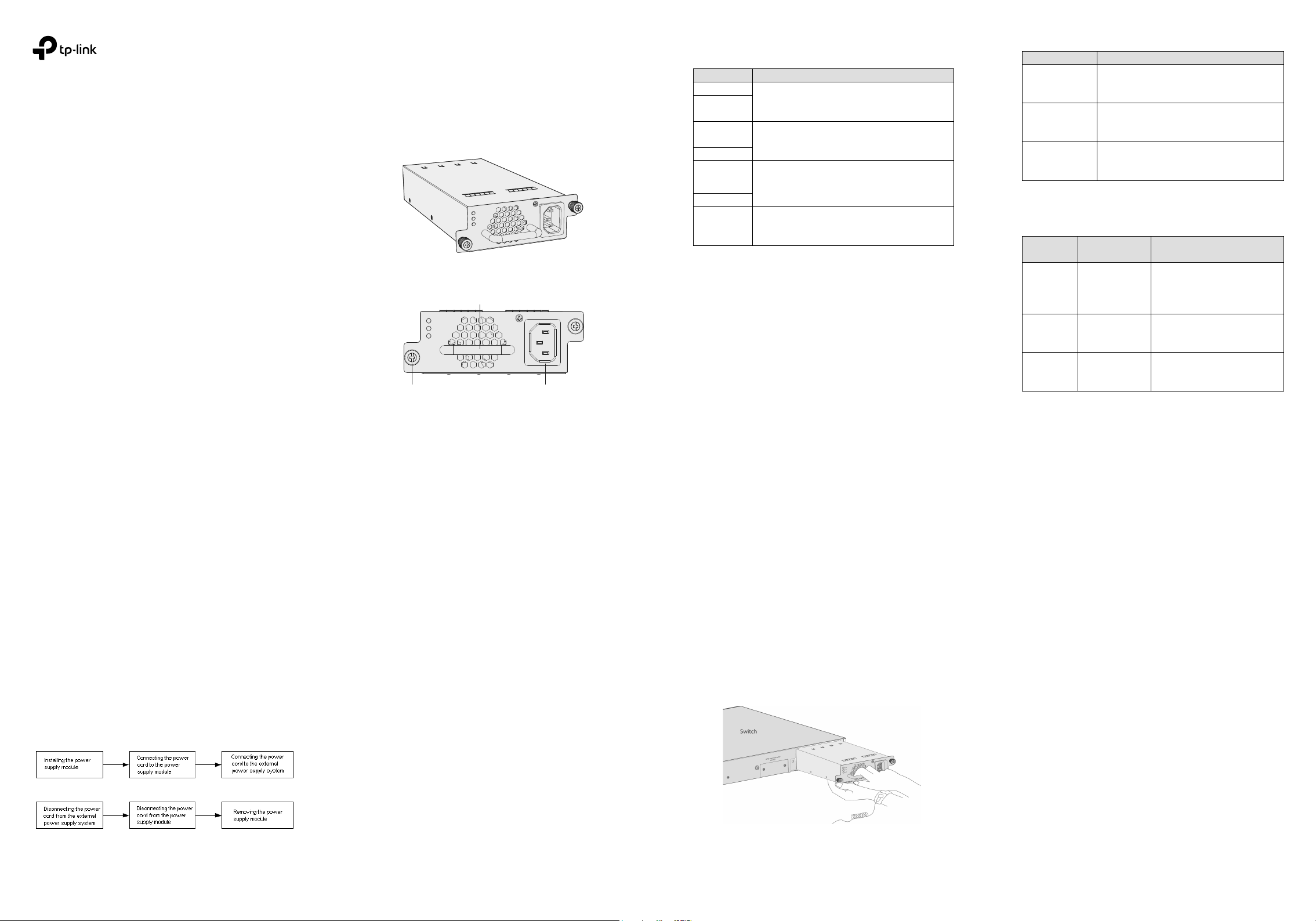
Figure 1-1 Appearance of PSM150-AC
Power
PS OK
Fault
PSM150-AC
100-240~50/60Hz 1.8A
Fastening Screw
AC power input jack
Power supply module handle
Figure 1-2 Front Panel of PSM150-AC
Power
PS OK
Fault
PSM150-AC
100-240~50/60Hz 1.8A
1.2 Description of LEDs
There are three LEDs on the front panel of PSM150-AC.
LED Status
Description
Power On
Power supply module is powered on and running well, but not
supplying power to the switch.
PS OK Off
Fault Off
Power On
PS OK On
Power supply module is powered on and running well, and
supplying power to the switch.
Fault Off
Power On
Fault On
The circuit has faults, such as output over-voltage, output
under-voltage, output over-current, output short circuit,
hot-swap control failure (note 1) or fan fault.
PS OK Off
Power Off
PS OK Off
Fault Off
AC power off or power supply fault.
Table 1-1 LED Status
Note:
• Hot-swap control function will be checked when
PSM150-AC is powered on but has not been inserted into
the switch. If the Fault LED is on under this condition,
please do not insert PSM150-AC into the switch,
otherwise the power supply module or the powered
devices may be damaged.
• The failure of output over-voltage or over-current may
cause the power LED to flash.
1.3 Description of Features
Feature
Description
Protection function
Includes output over-voltage protection, output
under-voltage protection, output short circuit protection
and output over-current protection .
Redundant backup
Supports dual power modules combining in p arallel to
implement 1+1 redundancy for uninterruptible power
supply.
Hot Swappable
In the case of 1+1 redundant power supply system, the
PSM150-AC can be plugged out or plugged in without
shutting down the switch.
Table 1-2 Features of PSM150-AC
When the power module reverts to the protected state, its
recovery characteristics are shown in Table 1-3.
Protection
function
Protective
action
Recovery characteristics
Output
over-voltage &
under-voltage
protection
Power supply module
locked and cut-off
supply
The power supply can not recover
automatically.
Output short
circuit
protection
Power supply module
locked and cut-off
supply
Power supply module reverts into the
auto-retry mode. It can recover
automatically when the fault is cleared.
Output
over-current
protection
Power supply module
locked and cut-off
supply
Power supply module reverts into the
auto-retry mode. It can recover
automatically when the fault is cleared.
Table 1-3 Protection Functions of PSM150-AC
Note: When the power supply module is locked or auto-retry
continually, you can try the following steps to restore the
device.
1. Disconnect the power cord from the external power
supply system.
2. Disconnect the power cord from the power supply
module.
3. Remove the power supply module from the switch.
4. Insert the power supply module again.
5. Connect the power cord to the power supply module
again.
6. Connect the other end of the power cord to the external
supply system.
Chapter 2 Installation
The process of installation and removal of the power supply
module is illustrated in Figure 2-1 and Figure 2-2.
Figure 2-1 The Installation Process
Figure 2-2 The Removal Process
Note: For safety considerations, the above process are
recommended by TP-Link, however, PSM150-AC can also
support installation or removal when the AC power supply is
on.
2.1 Safety Information
To avoid damage to the power supply module and the
equipment and bodily injury, please observe the following
notes:
• When you install and remove the power supply module,
please wear an ESD-preventive wrist strap, and make sure
that it has good skin contact and is well grounded.
• Before installing the power supply module, make sure that
the voltage of external power supply system is the same
with the voltage marked in the power supply module, and
the output voltage of the power supply module is the
same with the required voltage of the powered devices in
order to prevent damaging the power supply module or
the powered devices.
• Do not touch any exposed wires or terminals to avoid
bodily injury.
• Do not place the power module in a humid place or let the
liquid into the power supply module.
• If there is a failure inside the module, please contact
service personnel, instead of opening the housing of the
module.
2.2 Tools for Installation
• Straight screwdriver
• Philips screwdriver
• ESD-preventive wrist strap
2.3 Installing & Removing the Power Supply Module
• Installing the Power Supply Module
1. Wear an ESD-preventive wrist strap, and make sure that it
has good skin contact and is well grounded.
2. Grip the handle of the module with one hand, and hold the
bottom of the module using your other hand. Gently push
the module in along the slot guide rail until the module is
flush with the switch, as shown in Figure 2-3.
Figure 2-3 Install Power Supply Module
3. Tighten the captive screws with a Phillips screwdriver to
fix the power supply module in place.
• Removing the Power Supply Module
1. Wear an ESD-preventive wrist strap, and make sure that it
has good skin contact and is well grounded.
2. Remove the power cord from the external power supply
system and the power module.
3. Use a Phillips screwdriver to loosen the captive screws at
both sides of the power supply module until all spring
pressure is released.
4. Pull the handle with one hand towards you along the guide
rails, and hold the bottom of the module using your other
hand, until it completely comes out of the switch chassis.
Note:
When installing or removing a power supply module, pay
attention to the following points:
• Make sure that the power supply module is set correctly
in the operation of installation.
• Do not use too much force in the installation. If resistance
is encountered or positions of the power supply module
appear larger during installation, you must first remove
the module and then reinstall the module.
• If screws cannot be tighten, it may be due to the power
supply module is not installed properly. Please check
carefully.
Page 2
• In order to better protect the power supply module during
removal, it is recommended that you package it in an
antistatic bag.
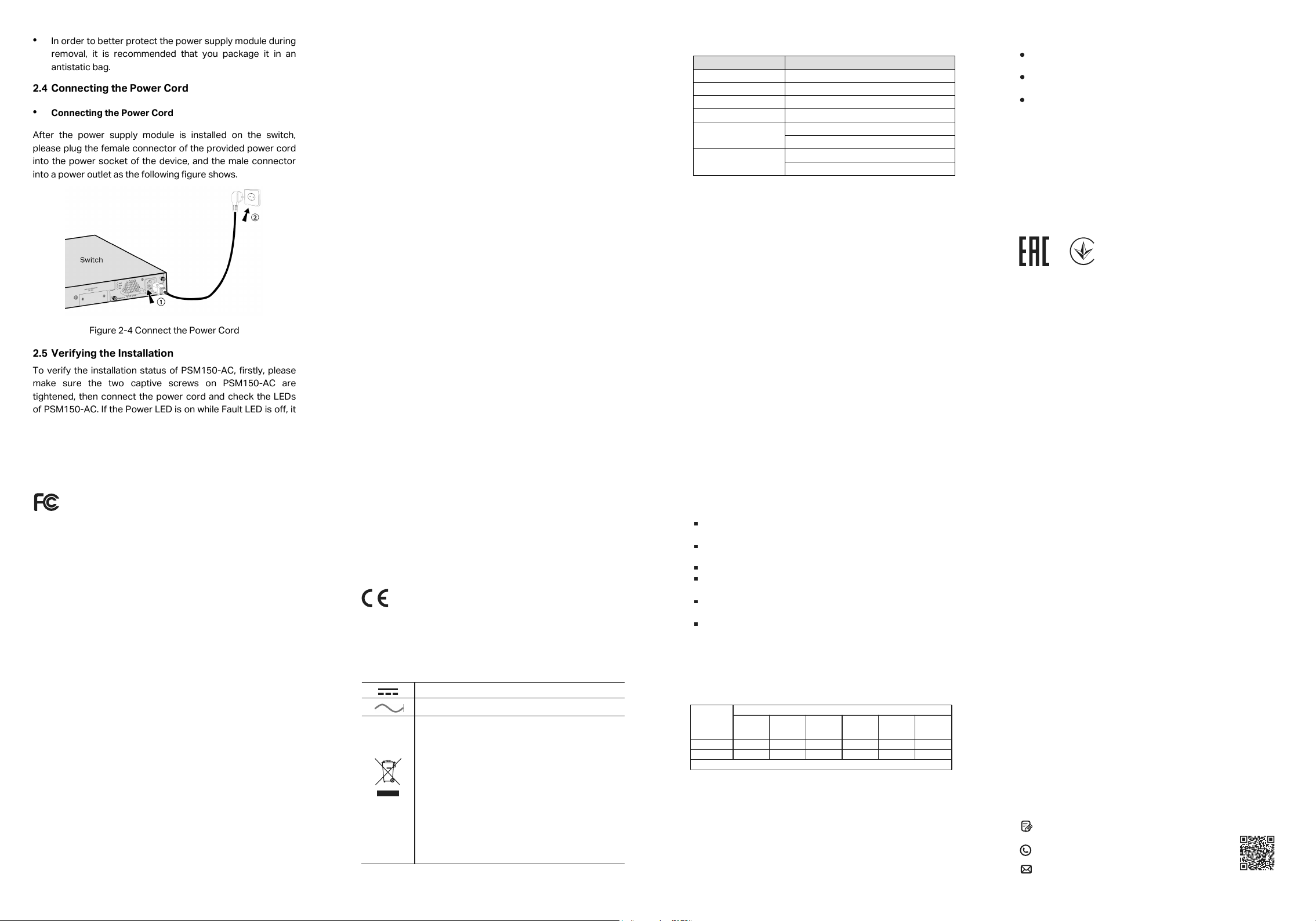
2.4 Connecting the Power Cord
• Connecting the Power Cord
After the power supply module is installed on the switch,
please plug the female connector of the provided power cord
into the power socket of the device, and the male connector
into a power outlet as the following figure shows.
Figure 2-4 Connect the Power Cord
2.5 Verifying the Installation
To verify the installation status of PSM150-AC, firstly, please
make sure the two captive screws on PSM150-AC are
tightened, then connect the power cord and check the LEDs
of PSM150-AC. If the Power LED is on while Fault LED is off, it
indicates that the AC power input is good and the device is
working properly, and the installation of PSM150-AC has been
successful.
Appendix: Specifications
Item
Specification
AC Power Input
100 V–240 V ~ 50/60 Hz
Output Voltage
12 VDC
Output Current
6.25 A (Maximum)
Output Power
75 W (Maximum)
Temperature
Operation : 0°C to 40°C (32 to 104°F)
Storage: -40°C to 70°C (-40 to 158°F)
Humidity
Operation : 20% to 90% RH Non-condensing
Storage: 10% to 95% RH Non-condensing
Safety Information
Keep the device away from water, re, humidity or hot
environments.
Do not attempt to disassemble, repair, or modify the device. If
you need service, please contact us.
Avoid using this product during an electrical storm. There may
be a remote risk of electric shock from lightning.
EU Declaration of Conformity
TP-Link hereby declares that the device is in compliance with
the essential requirements and other relevant provisions of
directives 2014/30/EU, 2014/35/EU, 2009/125/EC, 2011/65/EU
and (EU)2015/863.
The original EU declaration of conformity may be found at
https://www.tp-link.com/en/ce.
CAN ICES-3 (A)/NMB-3(A)
Industry Canada Statement
この装置は、クラスA情報技術装置です。この装置を家庭環境
で使用すると電波妨害を引き起こすことがあります。この場合
には使用者が適切な対策を講ずるよう要求されることがありま
す。 VCCI-A
FCC compliance information statement
This equipment has been tested and found to comply with the
limits for a Class A digital device, pursuant to part 15 of the FCC
Rules. These limits are designed to provide reasonable
protection against harmful interference when the equipment is
operated in a commercial environment. This equipment
generates, uses, and can radiate radio frequency energy and, if
not installed and used in accordance with the instruction
manual, may cause harmful interference to radio
communications. Operation of this equipment in a residential
area is likely to cause harmful interference in which case the
user will be required to correct the interference at his own
expense.
Product Name: AC Power Supply Module
Model Number: PSM150-AC
Responsible party:
TP-Link USA Corporation, d/b/a TP-Link North America, Inc.
Address: 145 South State College Blvd. Suite 400, Brea, CA
92821
Website: https://www.tp-link.com/us/
Tel: +1 626 333 0234
Fax: +1 909 527 6803
E-mail: sales.usa@tp-link.com
We, TP-Link USA Corporation, has determined that the
equipment shown as above has been shown to comply with the
applicable technical standards, FCC part 15. There is no
unauthorized change is made in the equipment and the
equipment is properly maintained and operated.
Issue Date: 2020/04/29
This is a class A product. In a domestic environment, this
product may cause radio interference, in which case the user
may be required to take adequate measures.
CE Mark Warning
This device complies with part 15 of the FCC Rules. Operation is
subject to the following two conditions:
1) This device may not cause harmful interference.
2) This device must accept any interference received, including
interference that may cause undesired operation.
Any changes or modications not expressly approved by the
party responsible for compliance could void the user’s authority
to operate the equipment.
Explanation of the symbols on the product label
DC voltage
RECYCLING
This product bears the selective sorting symbol
for Waste electrical and electronic equipment
(WEEE). This means that this product must be
handled pursuant to European directive
2012/19/EU in order to be recycled or
dismantled to minimize its impact on the
environment.
User has the choice to give his product to a
competent recycling organization or to the
retailer when he buys a new electrical or
electronic equipment.
AC voltage
BSMI Notice
安全諮詢及注意事項
請使用原裝電源供應器或只能按照本產品注明的電源類型
使用本產品。
清潔本產品之前請先拔掉電源線。請勿使用液體、噴霧清潔
劑或濕布進行清潔。
注意防潮,請勿將水或其他液體潑灑到本產品上。
插槽與開口供通風使用,以確保本產品的操作可靠並防止過
熱,請勿堵塞或覆蓋開口。
請勿將本產品置放於靠近熱源的地方。除非有正常的通風,
否則不可放在密閉位置中。
請不要私自拆開機殼或自行維修,如產品有故障請與原廠或
代理商聯繫。
此為甲類資訊技術設備,于居住環境中使用時,可能會造成射
頻擾動,在此種情況下,使用者會被要求採取某些適當的對策。
限用物質含有情況標示聲明書
產品元件名稱
PCB
外殼
產品元件名稱
PCB
外殼
限用物質及其化學符號
備考: "○"系指該項限用物質之百分比含量未超出百分比含量基準值。
鉛
Pb
○
○
鎘
Cd
○
○
汞
Hg
○
○
六價鉻
Cr
+6
○
○
多溴聯苯
PBB
○
○
多
溴二苯醚
PBDE
○
○
For technical support and other information, please visit
https://www.tp-link.com/support, or simply scan the QR code.
If you have any suggestions or needs on the product guides,
welcome to email techwriter@tp-link.com.cn.
To ask questions, find answers, and communicate with TP-Link
users or engineers, please visit https://community.tp-link.com
to join TP-Link Community.
 Loading...