

Page 1

User Guide
For TP-Link Pharos Series Products
CPE210 / CPE220 / CPE510 / CPE520 / CPE605 / CPE610
WBS210 / WBS510
1910012554 REV 3.1.0
March 2019
Page 2

CONTENTS
About this User Guide ......................................................................................................... 1
Overview ................................................................................................................................. 2
1 Operation Modes ........................................................................................................... 3
1.1 Access Point ................................................................................................................................................ 4
1.2 Client ............................................................................................................................................................... 5
1.3 Repeater (Range Extender) .................................................................................................................... 6
1.4 Bridge ............................................................................................................................................................. 7
1.5 AP Router ...................................................................................................................................................... 7
1.6 AP Client Router (WISP Client) .............................................................................................................. 8
2 Quick Start ....................................................................................................................... 9
2.1 Check the System Requirements ......................................................................................................10
2.2 Log In to the Device ................................................................................................................................10
2.3 Set Up the Wireless Network ...............................................................................................................11
Access Point .................................................................................................................................................. 12
Client ............................................................................................................................................................... 16
Repeater (Range Extender) ...................................................................................................................... 19
Bridge ............................................................................................................................................................... 23
AP Router ........................................................................................................................................................ 27
AP Client Router (WISP Client) ................................................................................................................ 32
3 Monitor the Network ..................................................................................................38
3.1 View the Device Information ................................................................................................................39
3.2 View the Wireless Settings ...................................................................................................................39
3.3 View Wireless Signal Quality................................................................................................................40
3.4 View Radio Status ....................................................................................................................................41
3.5 View the LAN Settings ............................................................................................................................43
3.6 View the WAN Settings ..........................................................................................................................43
Page 3

3.7 Monitor Throughput ................................................................................................................................44
3.8 Monitor Stations .......................................................................................................................................44
3.9 Monitor Interfaces ...................................................................................................................................45
3.10 Monitor ARP Table ...................................................................................................................................46
3.11 Monitor Routes .........................................................................................................................................46
3.12 Monitor DHCP Clients .............................................................................................................................47
3.13 Monitor Dynamic WAN ...........................................................................................................................47
4 Configure the Network .............................................................................................. 49
4.1 Configure WAN Parameters .................................................................................................................50
4.2 Configure LAN Parameters ..................................................................................................................57
Access Point/Client/Repeater/Bridge Mode ..................................................................................... 57
AP Router/AP Client Router Mode ......................................................................................................... 60
4.3 Configure Management VLAN ............................................................................................................62
4.4 Configure the Forwarding Feature ....................................................................................................62
4.5 Configure the Security Feature ..........................................................................................................66
4.6 Configure Access Control ....................................................................................................................69
4.7 Configure Static Routing .......................................................................................................................70
4.8 Configure Bandwidth Control ..............................................................................................................71
4.9 Configure IP & MAC Binding .................................................................................................................73
5 Configure the Wireless Parameters ..................................................................... 75
5.1 Configure Basic Wireless Parameters .............................................................................................76
5.2 Configure Wireless Client Parameters ............................................................................................78
5.3 Configure Wireless AP Parameters ...................................................................................................82
5.4 Configure Multi-SSID ..............................................................................................................................88
5.5 Configure Wireless MAC Filtering .....................................................................................................90
5.6 Configure Advanced Wireless Parameters ....................................................................................91
6 Manage the Device ..................................................................................................... 94
6.1 Manage System Logs .............................................................................................................................95
Page 4

6.2 Specify the Miscellaneous Parameters ...........................................................................................96
6.3 Configure Ping Watch Dog ...................................................................................................................97
6.4 Configure Dynamic DNS ........................................................................................................................98
6.5 Configure Web Server............................................................................................................................99
6.6 Configure SNMP Agent ....................................................................................................................... 100
6.7 Configure SSH Server ......................................................................................................................... 102
6.8 Configure RSSI LED Thresholds ...................................................................................................... 102
7 Configure the System ............................................................................................. 104
7.1 Configure Device Information .......................................................................................................... 105
7.2 Configure Location Information ...................................................................................................... 105
7.3 Configure User Account ..................................................................................................................... 105
7.4 Configure Time Settings .................................................................................................................... 106
7.5 Update Firmware ................................................................................................................................... 108
7.6 Configure Other Settings ................................................................................................................... 109
8 Use the System Tools ............................................................................................. 110
8.1 Configure Ping ....................................................................................................................................... 111
8.2 Configure Traceroute .......................................................................................................................... 111
8.3 Test Speed .............................................................................................................................................. 112
8.4 Survey ....................................................................................................................................................... 113
8.5 Analyze Spectrum ................................................................................................................................. 115
Page 5

About this User Guide
This User Guide contains information for setup and management of TP-Link Pharos series
products. Please read this guide carefully before operation.
When using this guide, please notice that features of the product may vary slightly depending on
the model and software version you have, and on your location, language, and internet service
provider. All screenshots, images, parameters and descriptions documented in this guide are used
for demonstration only.
Some models featured in this guide may be unavailable in your country or region. For local sales
information, visit
The information in this document is subject to change without notice. Every effort has been made
in the preparation of this document to ensure the accuracy of the contents, but all statements,
information, and recommendations in this document do not constitute the warranty of any kind,
express or implied. Users must take full responsibility for their application of any products.
http://www.tp-link.com
.
Convention
Unless otherwise noted, the introduction in this guide takes CPE510 as an example.
More Info
The latest software, management app and utility can be found at Download Center at
https://www.tp-link.com/support
The Quick Installation Guide can be found where you find this guide or inside the package of the
product.
Specifications can be found on the product page at
.
https://www.tp-link.com
.
Our Technical Support contact information can be found at the Contact Technical Support page at
https://www.tp-link.com/support
To ask questions, find answers, and communicate with TP-Link users or engineers, please visit
https://community.tp-link.com
.
to join TP-Link Community.
1
Page 6

Overview
is TP-Link's next generation outdoor product series dedicated to long-distance
outdoor wireless networking solutions.
is a powerful Web-based operating system, which is integrated into all Pharos series
products.
New features of Pharos series products are listed as follows:
• Provides User-friendly UI design.
• TP-Link Pharos MAXtream (Time-Division-Multiple-Access) technology improves product
performance in throughput, capacity and latency, which are ideal for point-to-multipoint
applications.
• Supports multiple operation modes: Access Point, Client, Repeater (Range Extender), Bridge, AP
Router and AP Client Router (WISP Client).
• Provides system-level optimization for long-distance wireless transmission.
• Supports selectable bandwidth of 5/10/20/40MHz.
• Supports easy antenna alignment with Wireless Signal Indicators on Web interface.
• Provides Throughput Monitor, Spectrum Analyzer, Speed Test and Ping tools.
• Supports discovery and management via Pharos Control application.
2
Page 7

1
The Pharos series products support six operation modes to satisfy user’s diversified
network requirements. This chapter introduces typical usage scenarios of different
modes, including:
1.1 Access Point
1.2 Client
1.3 Repeater (Range Extender)
1.4 Bridge
1.5 AP Router
1.6 AP Client Router (WISP Client)
Operation Modes
3
Page 8
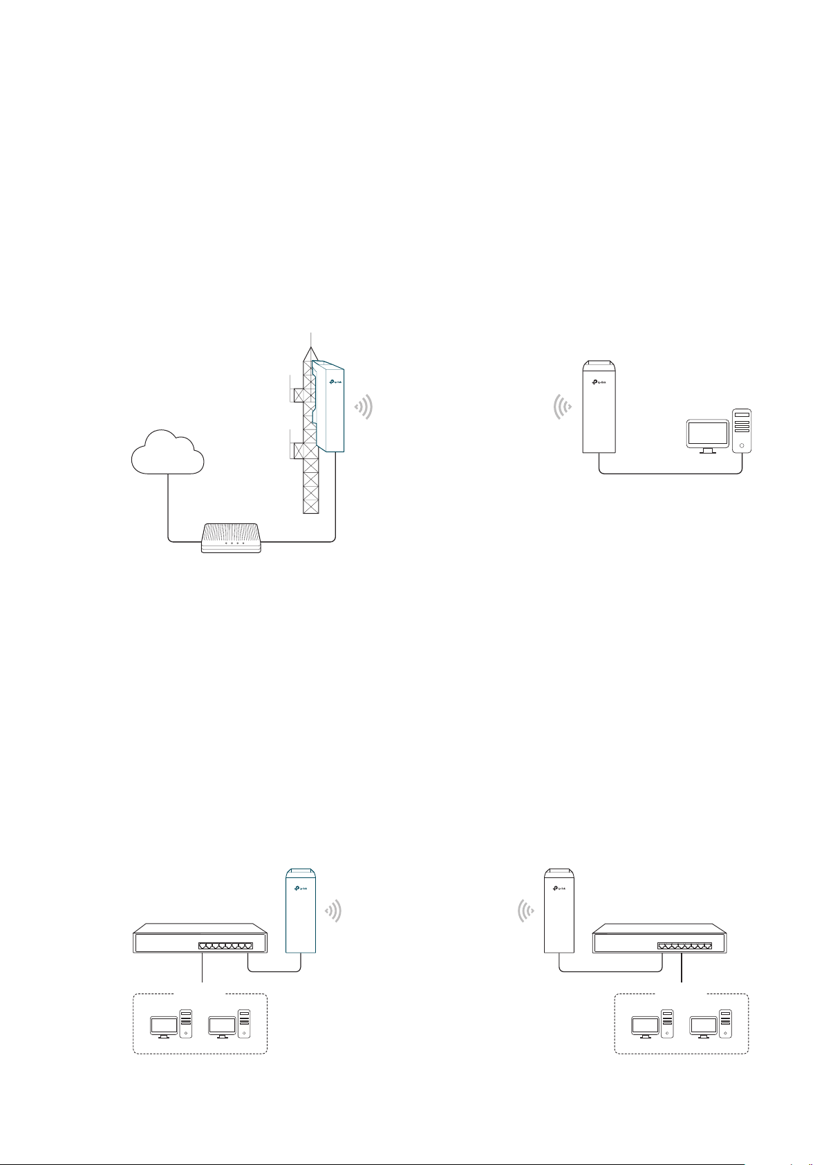
1.1 Access Point
In AP mode, the device acts as a central hub and provides wireless access point for
wireless clients, thus the AP mode is applicable to the following three scenarios.
Meanwhile, Multi-SSID function can be enabled in this mode, providing up to four wireless
networks with different SSIDs and passwords.
Scenario 1
Access Point
LAN: 192.168.7.2
Internet
Router
LAN: 192.168.7.1
AP Client Router
LAN: 192.168.0.254
WAN: Dynamic IP
Network requirements: Establish the network coverage in the remote areas without long-
distance cabling.
The device in the network: In the adjacent town covered by wired network, ISP (Internet
Service Provider) can put up a device in AP mode to access the internet and transform
wired signal into wireless one. In the remote area, users can put up a device in AP Client
Router mode to access the wireless network.
Advantages: Transmit data wirelessly across a long distance and reduce the cabling cost.
Scenario 2
Access Point Client
LAN: 192.168.0.254 LAN: 192.168.0.2
Switch
Oce Oce
4
Switch
Page 9

Network requirements: Combine two separate office networks into one.
The device in the network: The device in AP mode connects to one office network
and creates a wireless network. The device in Client mode connects to the other office
network and the wireless network.
Advantages: Establish a point-to-point WLAN across a long distance to achieve the
connectivity between two networks and avoid the cabling trouble.
Scenario 3
Internet
Network requirements: Establish wireless network coverage in the campus, community,
industrial park or public place to provide wireless access for users.
The device in the network: With the access to campus wired network or other wired local
area networks, the device in AP mode provides the wireless access for wireless clients,
such as smart phones, laptops and tablets to connect to the network.
Advantages: Enrich the access ways of local area network and extend the network
coverage.
1.2 Client
Wired Local
Area Network
Access Point
Laptop/Tablet/Smartphone
For the device in Client mode, the most common usage scenario is point-to-point
networking. The device is used to transform wireless signal into wired one.
Access Point
LAN: 192.168.0.254
Switch
Oce Oce
5
Client
LAN: 192.168.0.2
Switch
Page 10
Network requirements: Help the wired devices to connect to the wireless network.
The device in the network: In Client mode, the device actually serves as a wireless adapter
to receive the wireless signal from root AP or Station. In this case, wired devices can
access the wireless network by connecting to the device in Client mode.
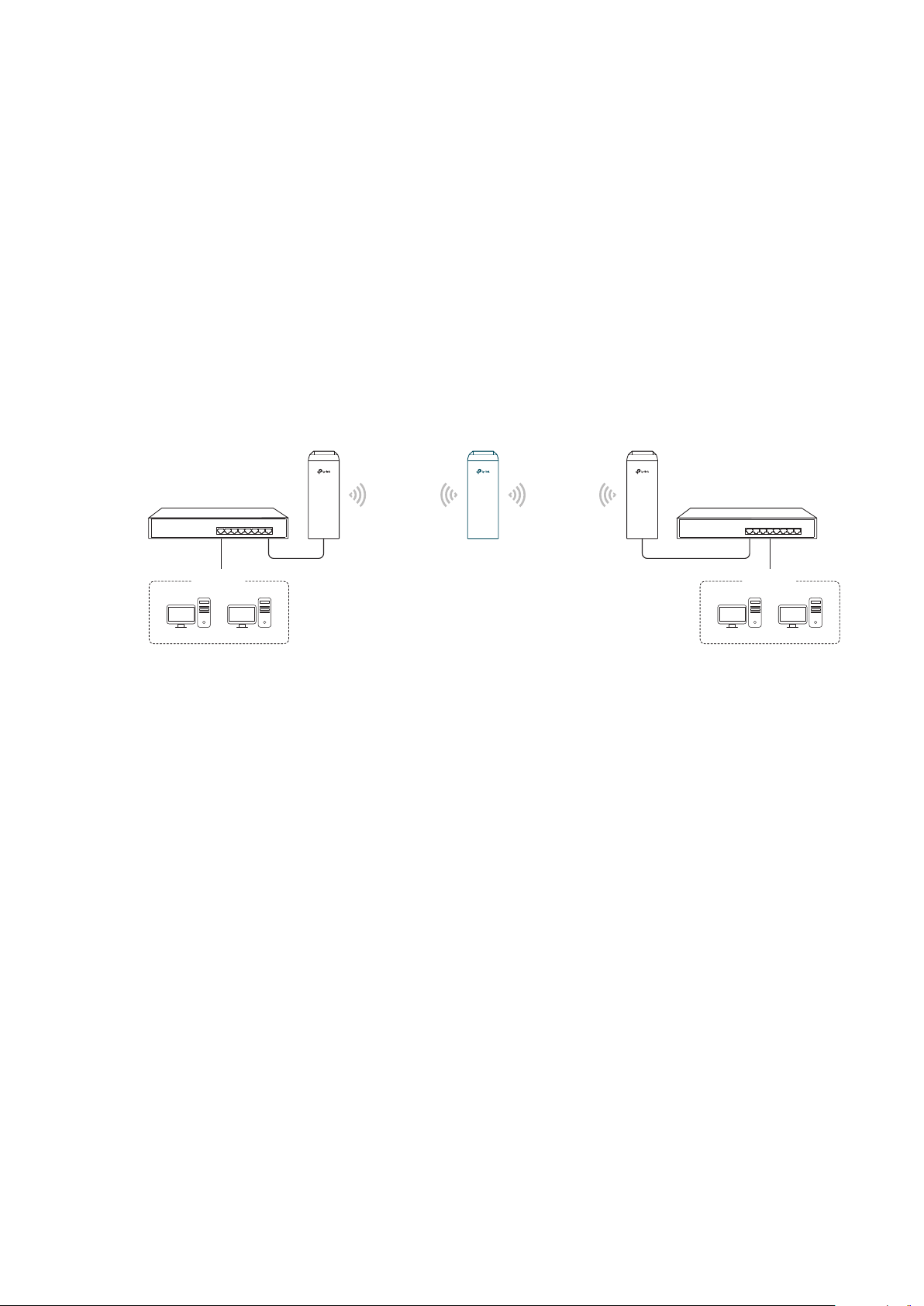
1.3 Repeater (Range Extender)
The device in Repeater mode can extend wireless coverage of an existing wireless
network. The SSID and encryption type of the device should be the same as those of the
root AP.
Access Point Client
LAN: 192.168.0.254
Switch
Oce Oce
SSID: abc
Repeater
LAN: 192.168.0.2 LAN: 192.168.0.3
SSID: abc
Switch
Network requirements: Repeat wireless signal and extend the wireless network coverage.
The device in the network: If you want to combine two networks via wireless connection
but the distance is beyond the networks’ wireless coverage range, you can put one or
more devices in Repeater mode along the path to repeat the wireless signal and extend
the wireless transmission range.
6
Page 11
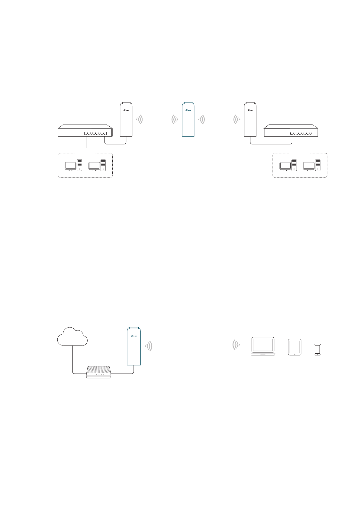
1.4 Bridge
The device in Bridge mode can extend wireless coverage of an existing wireless network.
The SSID and encryption type of the device can be different from those of root AP.
Access Point Client
LAN: 192.168.0.254
Switch
Oce Oce
SSID: abc
Bridge
LAN: 192.168.0.2 LAN: 192.168.0.3
SSID: 123
Switch
Network requirements: Extend the wireless network to eliminate the wireless signal-blind
areas. Users can use different SSID and encryption type from those of the root AP device
to access the network.
The device in the network: Similar to the Repeater mode, the Bridge mode is used to
enhance the exiting wireless signal. However, the difference is that the extended wireless
network has its own SSID and encryption type different from those of root AP.
1.5 AP Router
The device in AP Router mode serves as a normal home wireless router but provides a
wider wireless network range.
Internet
Modem
Network requirements: Establish the wireless network coverage in the campus,
community, industrial park or other public places and so on.
The device in the network: The device in AP Router mode connects to root ADSL/Cable
AP Router
Laptop/Tablet/Smartphone
7
Page 12

Modem for internet access. Meanwhile, it creates a wireless network for the wireless
clients to connect to the internet.
Note:
In this mode, the device cannot be managed directly through the port connected to ADSL/Cable
Modem. To manage the device, you can connect the management host to the device wirelessly or
via the other LAN port.
1.6 AP Client Router (WISP Client)
In AP Client Router mode, the device access the internet provided by WISP (Wireless
Internet Service Provider) through wireless connection. For the downstream clients, the
device serves as a normal home wireless router. It can provide wired connection and
wireless connection simultaneously.
AP Client Router
WISP
LAN: 192.168.0.254
WAN: Dynamic IP
WISP’s network
User Network
Network requirements: Get internet service from WISP.
The device in the network: The device in Client Router Mode connects to WISP wirelessly
for internet service. It provides both wired access and wireless access for the clients.
8
Page 13

2
This chapter introduces how to quickly build a wireless network in different operation
modes. Follow the steps below:
2.1 Check the System Requirements
2.2 Log In to the Device
2.3 Set Up the Wireless Network
Quick Start
9
Page 14
2.1 Check the System Requirements
Operating System:
Microsoft Windows XP, Windows Vista, Windows 7, Windows 8, Windows 10, Linux, or
Mac OS X.
Web Browser
Google Chrome, Safari, Firefox, and Apple Safari. IE browsers are not recommended.
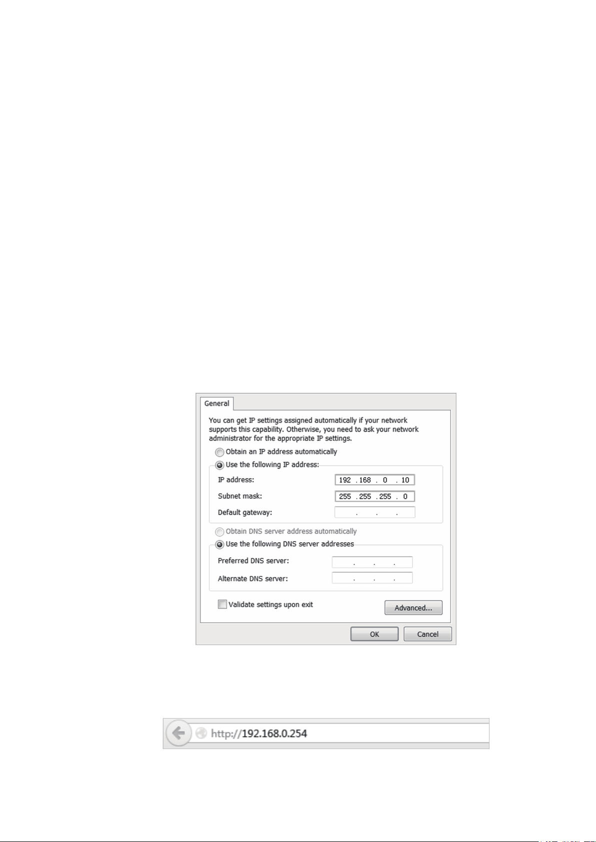
2.2 Log In to the Device
Before configuring the device, you need to access the PharOS configuration interface.
Follow the steps below:
1. Connect your PC to the device.
2. Set the IP address of your PC as static IP address on 192.168.0.X subnet (X ranges from
2 to 253, e.g.192.168.0.10).
3. Launch a web browser on and enter the management IP address of the device
(192.168.0.254 by default) in the address bar to load the login page of the PharOS
configuration interface.
10
Page 15
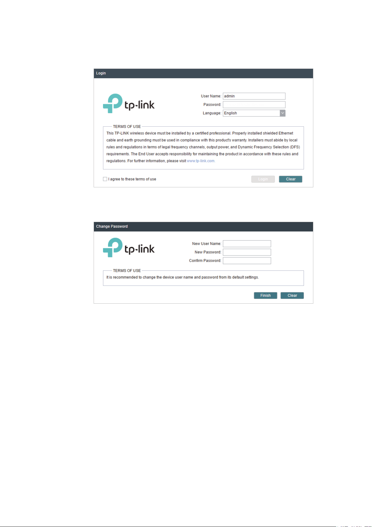
4. Use admin for both of
User Name
and
Password
. Select the appropriate language from
the Language drop-down list. Read and agree the terms of use, then click
5. Create a new username and password for network security. Click
PharOS.
Login
Finish
to log in to the
.
2.3 Set Up the Wireless Network
You can use the Quick Setup wizard to quickly configure your device step by step. Choose
the suitable operation mode according to your network environment and follow the step-
by-step instructions.
11
Page 16
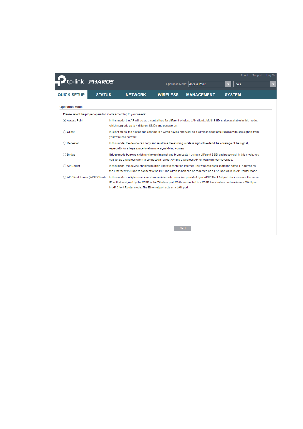
Access Point
Follow the steps below to configure the device as Access Point mode:
1. Go to the QUICK SETUP page, select
Access Point
and click
Next
.
12
Page 17
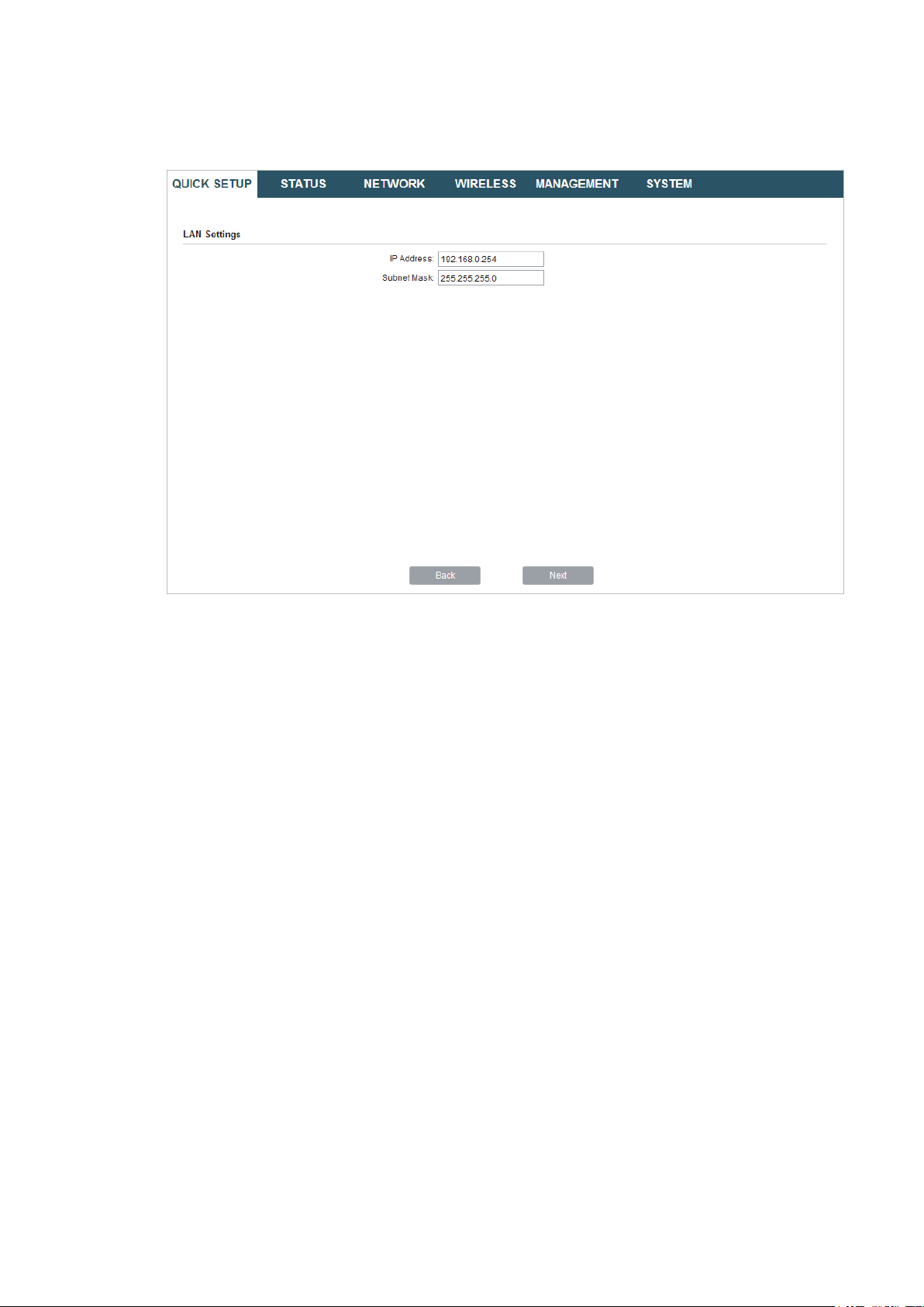
2. In the LAN Settings section, specify the LAN IP address and the Subnet Mask for the
device. Then, click
Next
.
13
Page 18
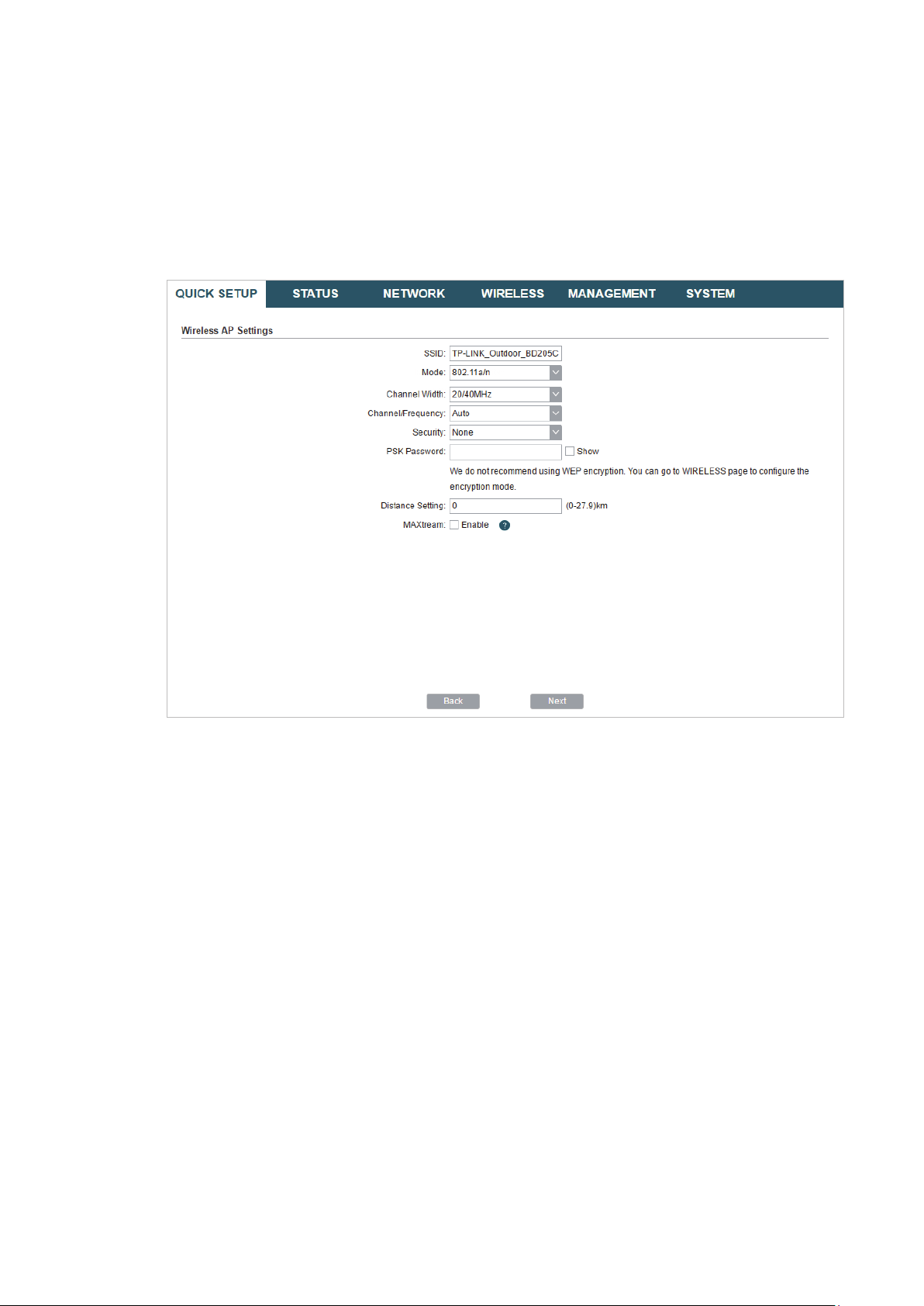
3. In the Wireless AP Settings section, specify the basic wireless parameters to create a
wireless network. Click
Next
.
Tips:
It is recommended to specify
·
You can keep the default settings or specify the parameters according to your need. For details,
·
refer to
5. Configure the Wireless Parameters
Security
as WPA-PSK/WPA2-PSK for the network security.
.
14
Page 19
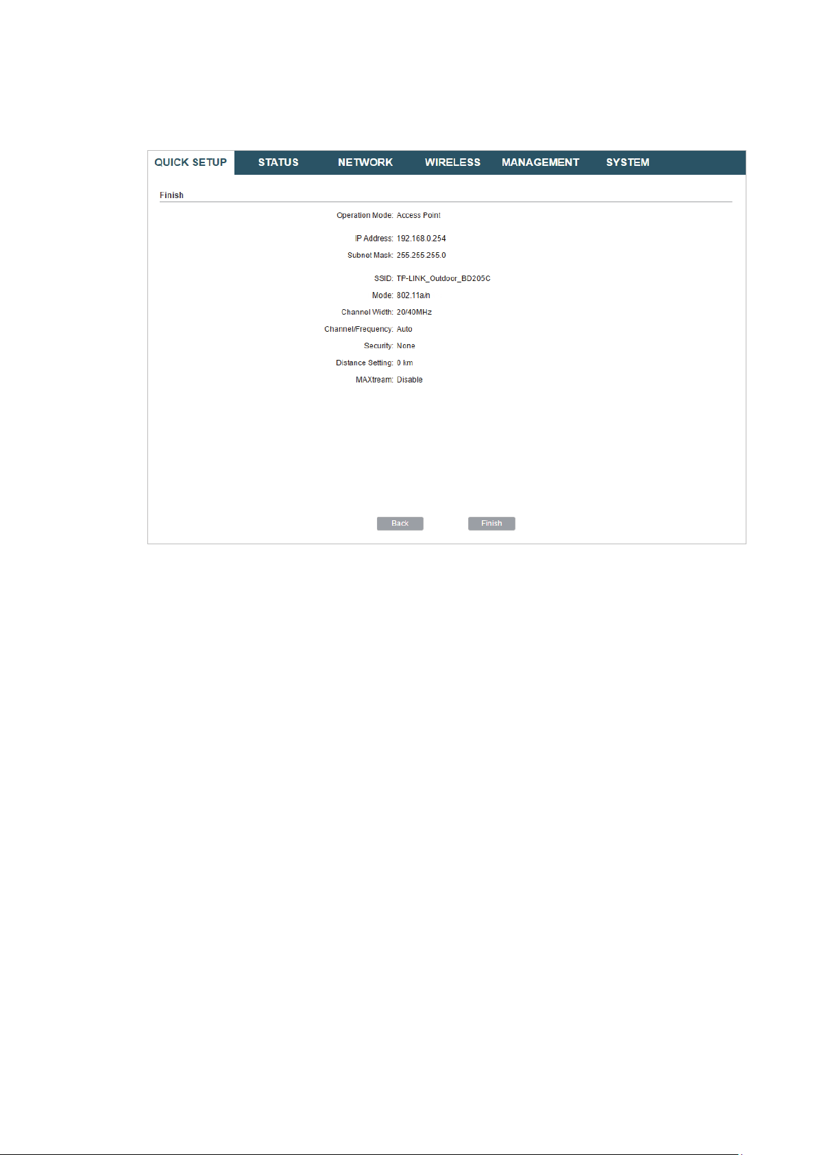
4. In the Finish section, review the configurations and click
setup.
Finish
to complete the quick
5. Connect the device according to your network topology and use it normally.
15
Page 20
Client
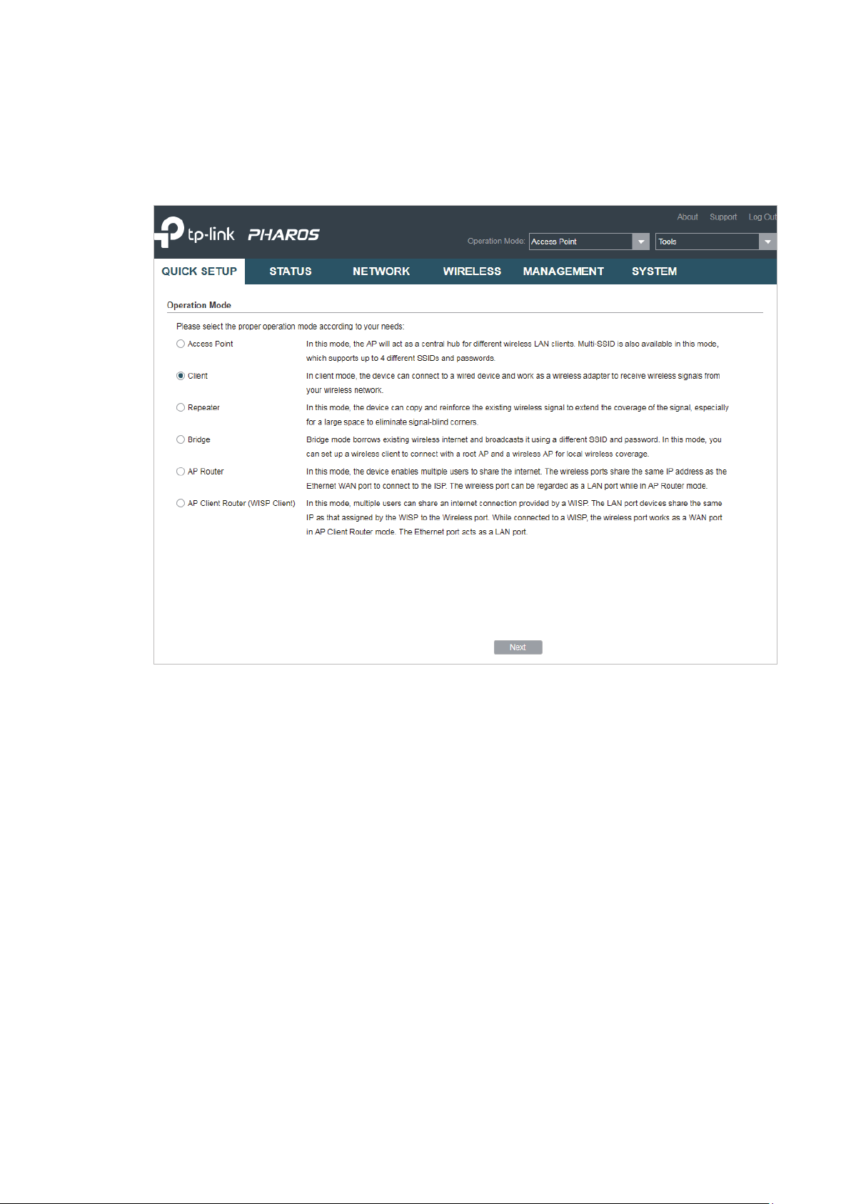
Follow the steps below to configure the device as Client mode:
1. Go to the QUICK SETUP page, select
Client
and click
Next
.
16
Page 21
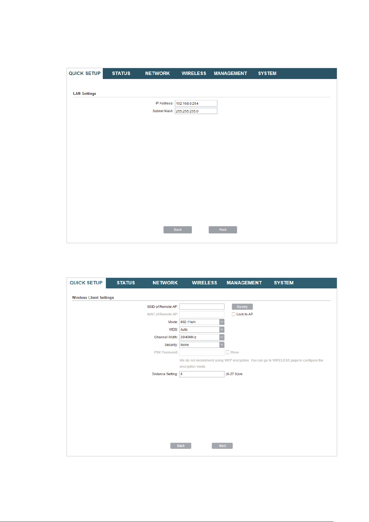
2. In the LAN Settings section, specify the LAN IP Address and the Subnet Mask for the
device. Then, click
Next
.
3. In the Wireless Client Settings section, click
network.
Survey
to search for the upstream wireless
4. Select the desired wireless network and click
17
Connect
.
Page 22
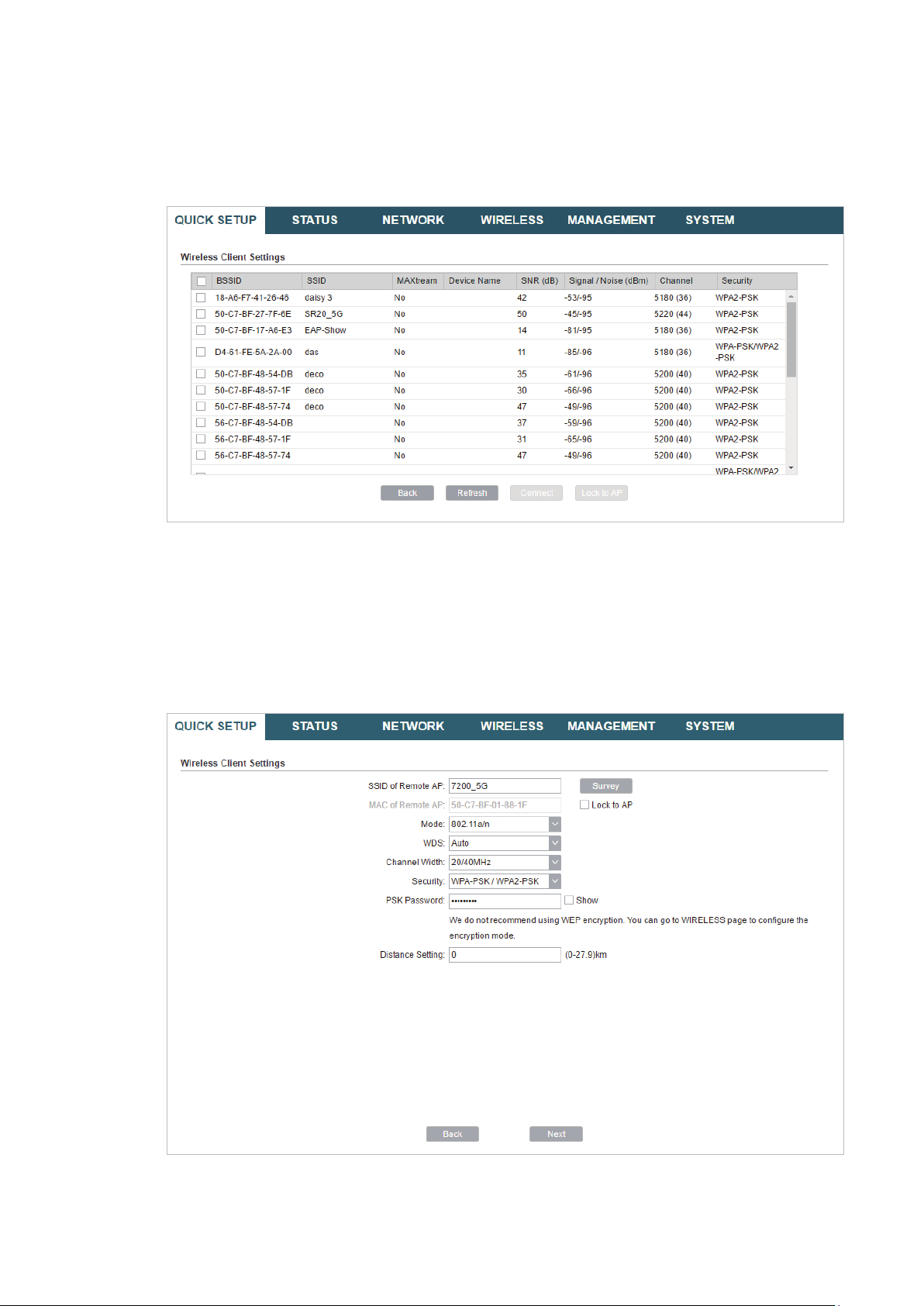
Tips:
There may be two or more networks with the same SSID in the AP list. Click
the SSID and AP simultaneously, which can make the device connect to the specific AP next
time.
Lock to AP
to select
5. In the Wireless Client Settings section, specify the wireless parameters to connect to
the specified wireless network. Click
Next
.
Note:
Make sure that
Other parameters set in this page and those of the upstream wireless network should be
compatible with each other. For details, refer to
Security
and
PSK Password
are the same as the upstream wireless network’s.
5. Configure the Wireless Parameters
.
18
Page 23
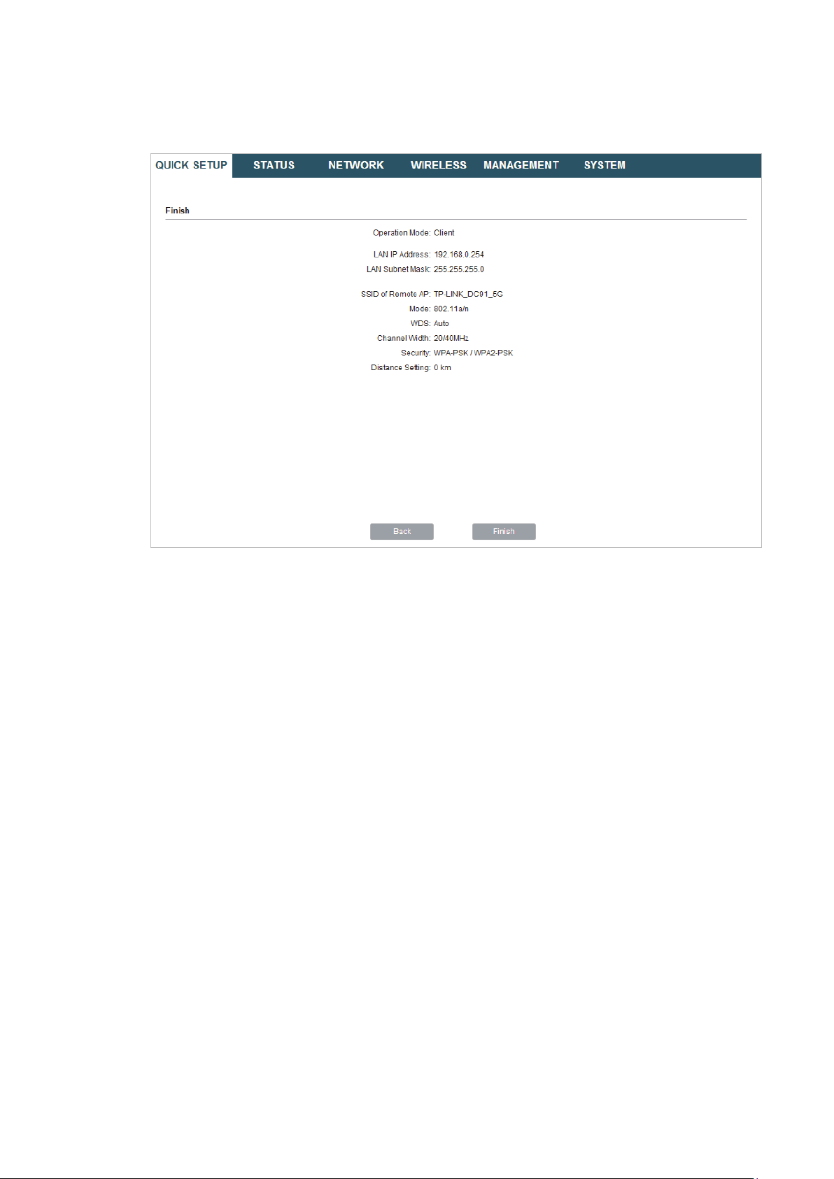
6. In the Finish section, review the configurations and click
setup.
Finish
to complete the quick
7. Connect the device according to your network topology and use it normally.
Repeater (Range Extender)
Follow the steps below to configure the device as Repeater (Range Extender) mode:
19
Page 24
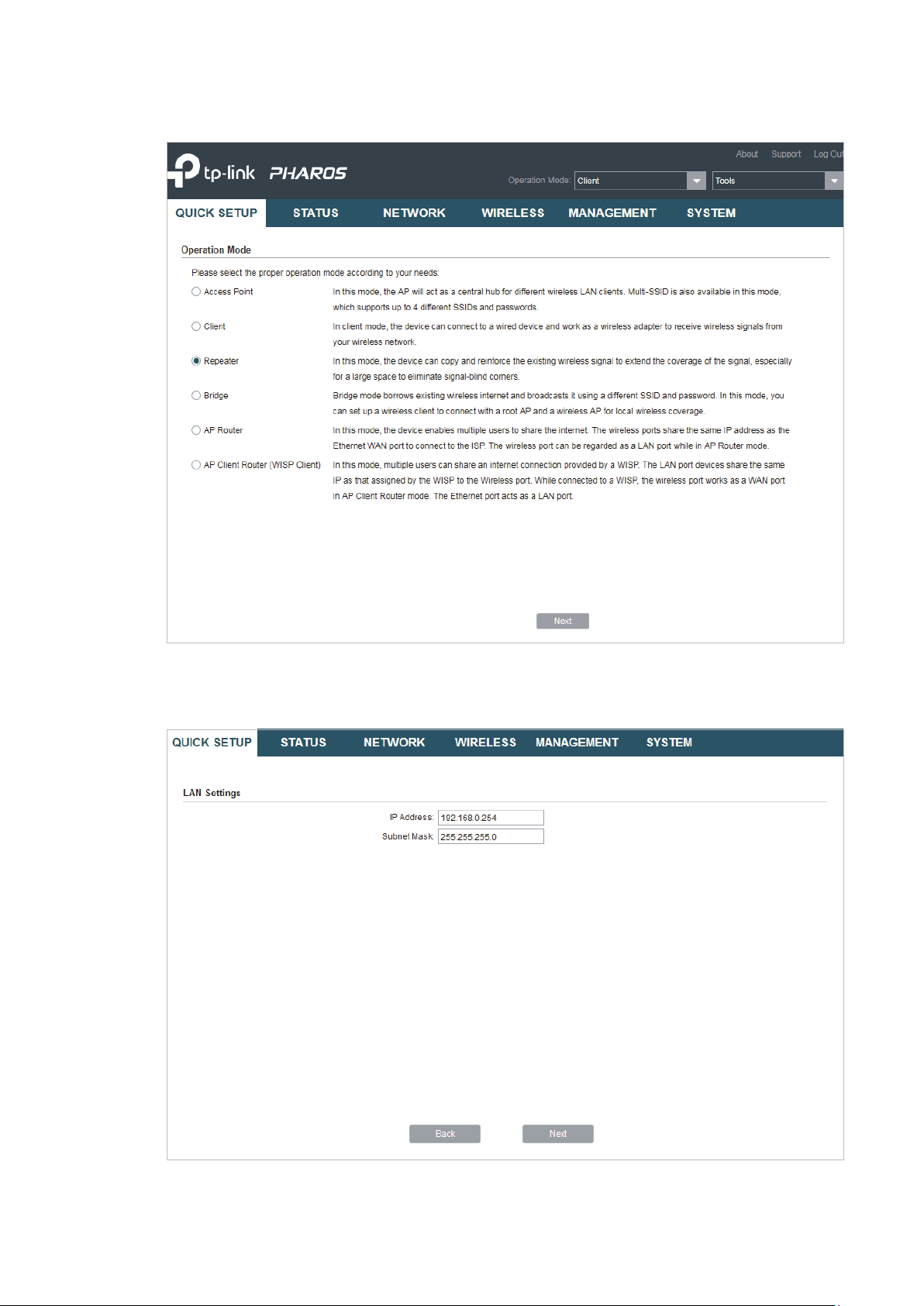
1. Go to the QUICK SETUP page, select
Repeater
and click
Next
.
2. In the LAN Settings section, specify the LAN IP address and the Subnet Mask for the
device. Then, click
Next
.
20
Page 25
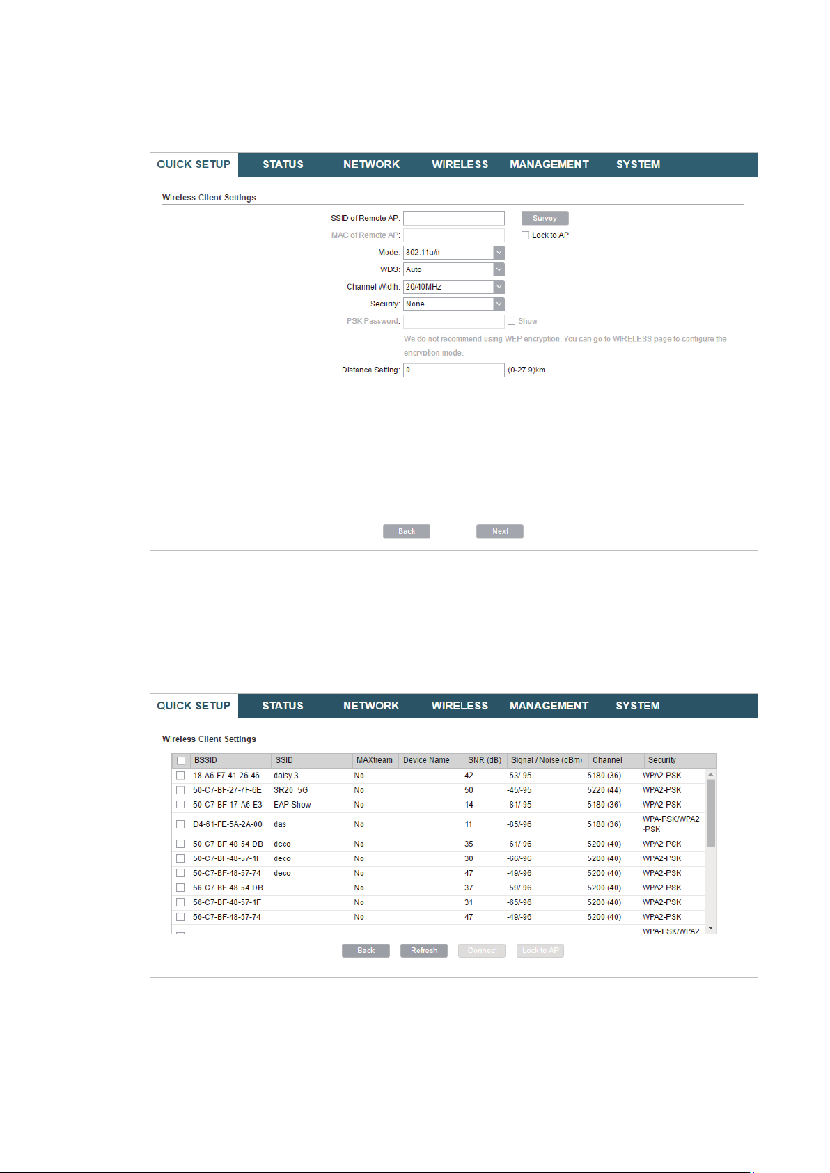
3. In the Wireless Client Settings section, click
network.
Survey
to search for the upstream wireless
4. Select the desired wireless network and click
Connect
.
Tips:
There may be two or more networks with the same SSID in the AP list. Click
the SSID and AP simultaneously, which can make the device connect to the specific AP next
time.
Lock to AP
to select
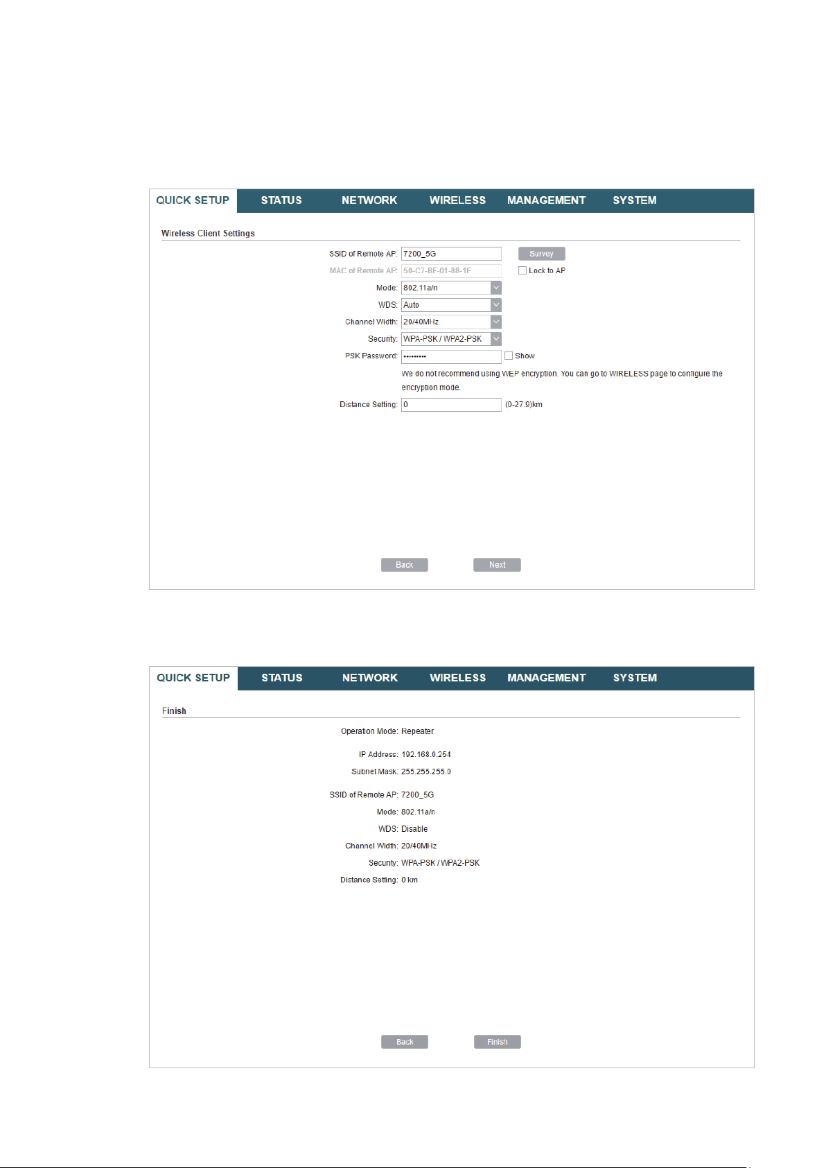
5. In the Wireless Client Settings section, specify the wireless parameters to connect to
the specified wireless network. Click
Next
21
.
Page 26
Note:
Make sure that
Other parameters set in this page and those of the upstream wireless network should be
compatible with each other. For details, refer to
Security
and
PSK Password
are the same as the upstream wireless network’s.
5. Configure the Wireless Parameters
.
6. In the Finish section, review the configurations and click
setup.
Finish
to complete the quick
22
Page 27
7. Connect the device according to your network topology and use it normally.
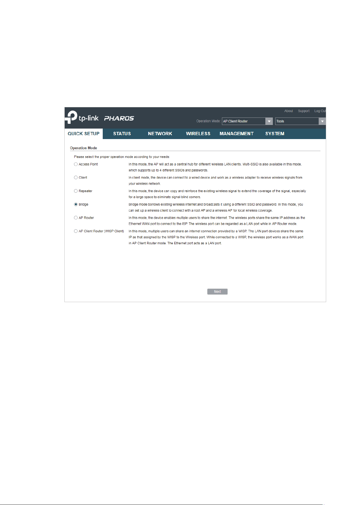
Bridge
Follow the steps below to configure the device as Bridge mode:
1. Go to the QUICK SETUP page, select
Bridge
and click
Next
.
23
Page 28
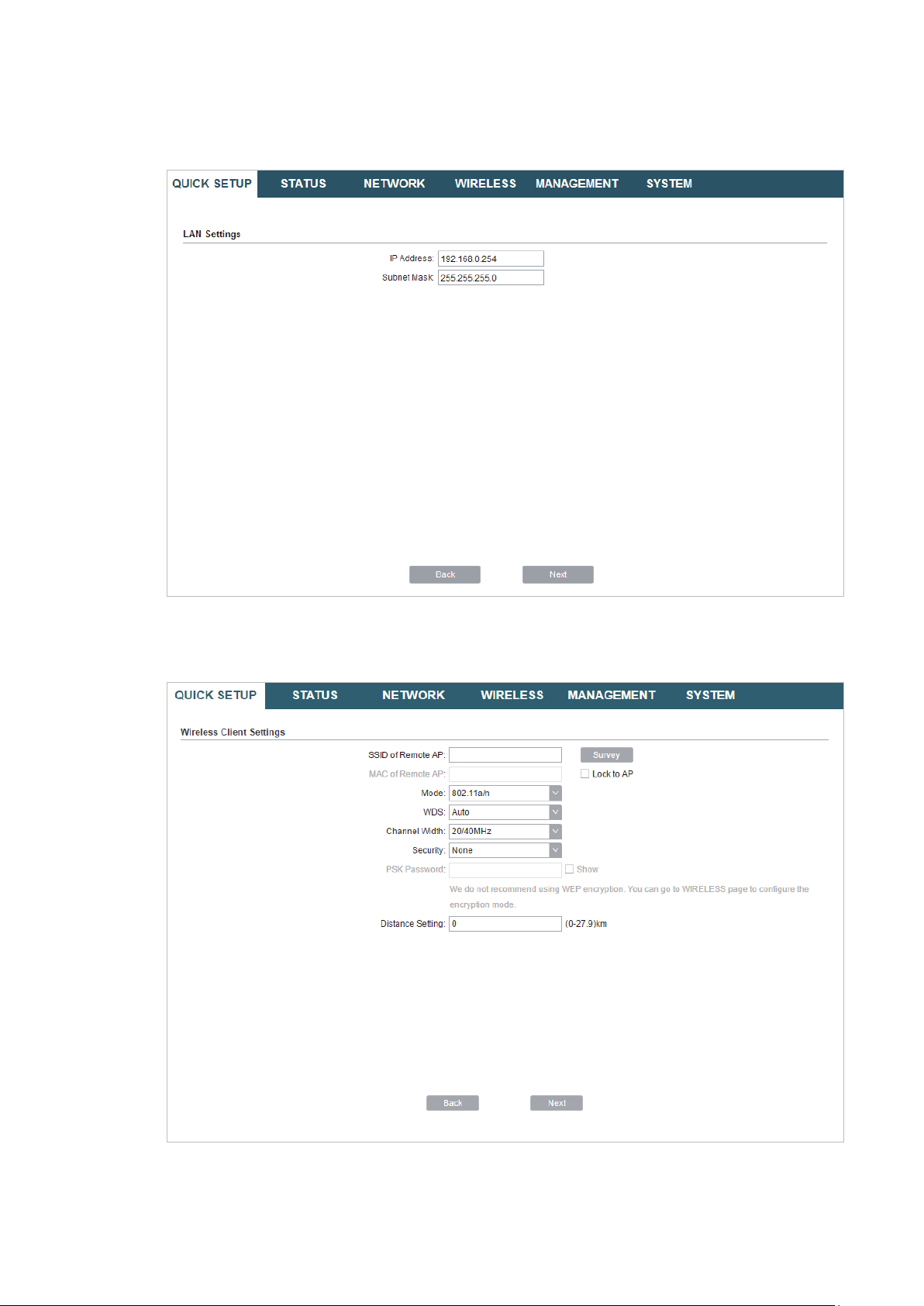
2. In the LAN Settings section, specify the LAN IP address and the Subnet Mask for the
device. Then, click
Next
.
3. In the Wireless Client Settings section, click
network.
Survey
to search for the upstream wireless
4. Select the desired wireless network and click
24
Connect
.
Page 29
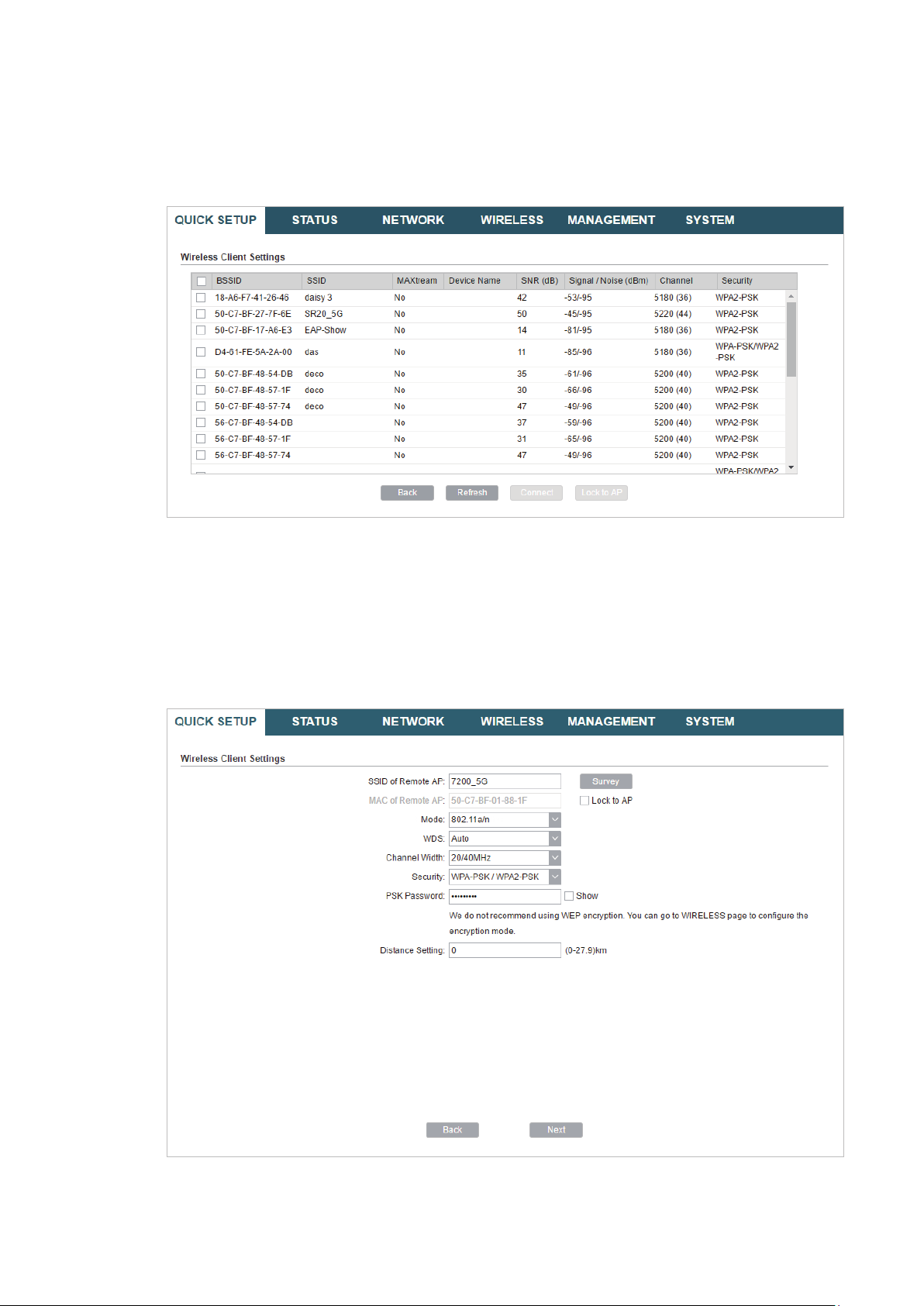
Tips:
There may be two or more networks with the same SSID in the AP list. Click
the SSID and AP simultaneously, which can make the device connect to the specific AP next
time.
Lock to AP
to select
5. In the Wireless Client Settings section, specify the wireless parameters to connect to
the specified wireless network. Click
Next
.
Note:
Make sure that the
Other parameters set in this page and those of the upstream wireless network should be
compatible with each other. For details, refer to
Security
and
PSK Password
are the same as the upstream wireless network’s.
5. Configure the Wireless Parameters
.
25
Page 30
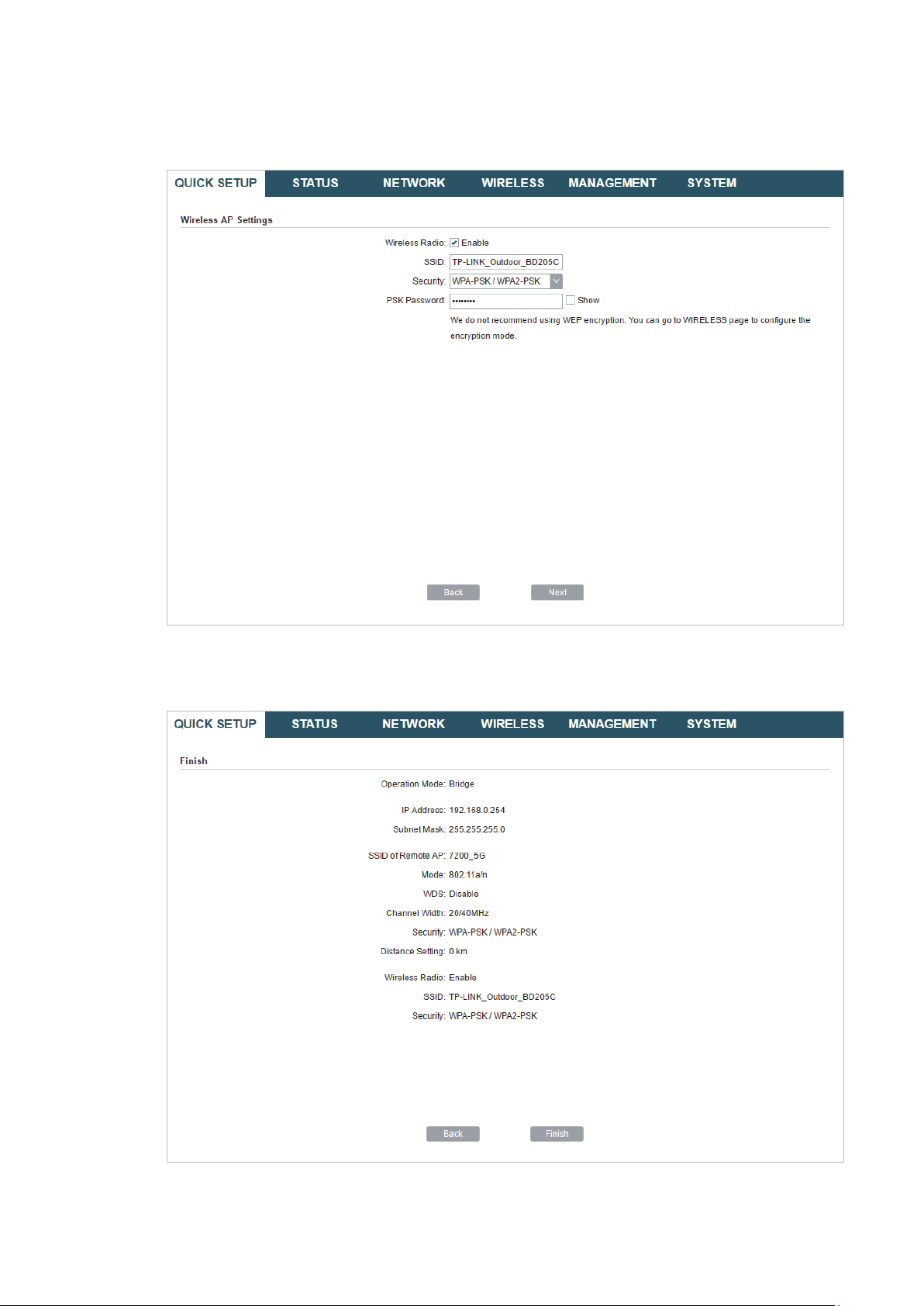
6. In the Wireless AP Settings section, specify the parameters to create a new wireless
network for the downstream clients. Click
Next
.
7. In the Finish section, review the configurations and click
setup.
Finish
to complete the quick
8. Connect the device according to your network topology and use it normally.
26
Page 31

AP Router
Follow the steps below to configure the device as AP Router mode:
1. Go to the QUICK SETUP page, select
AP Router
and click
Next
.
27
Page 32

2. In the WAN Connection Type section, specify the connection type according to your
need and click
Next
.
The device supports three types of the WAN connection, including
and
Static IP
. You can contact with your ISP to confirm your WAN connection type.
PPPoE, Dynamic IP
28
Page 33

PPPoE
Select
PPPoE
and click
Next
, then the following page will appear. In the WAN Settings
section, specify the parameters that are provided by your ISP and click
Next
.
Dynamic IP
Select
Dynamic IP
and click
Next
. In this type, the device will obtain a WAN connection
automatically without any WAN configurations.
29
Page 34

Static IP
Select
Static IP
and click
Next
, then the following page will appear. In the WAN Settings
section, specify the parameters that are provided by your ISP and click
Next
.
3. In the Wireless AP Settings section, specify the basic wireless parameters to create a
wireless network. Click
Next
.
30
Page 35

Tips:
It is recommended to specify
·
You can keep the default settings or specify the parameters according to your need. For details,
·
refer to
5. Configure the Wireless Parameters
Security
as WPA-PSK/WPA2-PSK for the network security.
.
4. In the Finish section, review the configurations and click
setup.
Finish
to complete the quick
31
Page 36

5. Connect the device according to your network topology and use it normally.
AP Client Router (WISP Client)
Follow the steps below to configure the device as AP Client Router (WISP Client) mode:
1. Go to the QUICK SETUP page, select
AP Client Router (WISP Client)
and click
Next
.
32
Page 37

2. In the WAN Connection Type section, choose the connection type according to your
need and click
Next
.
The device supports types,
PPPoE, Dynamic IP
and
Static IP
for the WAN connection.
You can contact with your ISP to confirm your WAN connection type.
33
Page 38

PPPoE
Select
PPPoE
and click
Next
, then the following page will appear. In the WAN Settings
section, specify the parameters that are provided by your ISP and click
Next
.
Dynamic IP
Select
Dynamic IP
and click
Next
. In this type, the device will obtain a WAN connection
automatically without any WAN configurations.
34
Page 39

Static IP
Select
Static IP
and click
Next
, then the following page will appear. In the WAN Settings
section, specify the parameters that are provided by your ISP and click
Next
.
3. In the Wireless Client Settings section, click
network.
Survey
to search for the upstream wireless
35
Page 40

4. Select the desired wireless network and click
Connect
.
Tips:
There may be two or more networks with the same SSID in the AP list. Click
the SSID and AP simultaneously, which can make the device connect to the specific AP next
time.
Lock to AP
to select
5. In the Wireless Client Settings section, specify the wireless parameters to connect to
the specified wireless network. Click
Next
.
Note:
Make sure that
Other parameters set in this page and those of the upstream wireless network should be
compatible with each other. For details, refer to
Security
and
PSK Password
are the same as the upstream wireless network’s.
5. Configure the Wireless Parameters
.
36
Page 41

6. In the Wireless AP Settings section, specify the parameters to create a new wireless
network for the downstream clients. Click
Next
.
7. In the Finish section, review the configurations and click
setup.
Finish
to complete the quick
8. Connect the device according to your network topology and use it normally.
37
Page 42

3
This chapter introduces how to monitor the running status and statistics of the wireless
network, including:
3.1 View the Device Information
3.2 View the Wireless Settings
3.3 View Wireless Signal Quality
3.4 View Radio Status
3.5 View the LAN Settings
3.6 View the WAN Settings
3.7 Monitor Throughput
3.8 Monitor Stations
Monitor the Network
3.9 Monitor Interfaces
3.10 Monitor ARP Table
3.11 Monitor Routes
3.12 Monitor DHCP Clients
3.13 Monitor Dynamic WAN
38
Page 43

3.1 View the Device Information
Go to the STATUS page. In the Device Information section, you can view the basic
information of the device. To configure the device information, refer to
System
.
Device Name Displays the name of the device. By default, it is the product model.
Device Model Displays the product model and the hardware version of the device.
Firmware
Version
System Time Displays the current system time.
Displays the current firmware version of the device.
7. Configure the
Uptime Displays the running time of the device.
CPU Displays the CPU occupancy.
Memory Displays the memory occupancy.
3.2 View the Wireless Settings
Go to the STATUS page. In the Wireless Settings section, you can view the parameters
of the wireless network created by the device. To configure the parameters, refer to
Configure the Wireless Parameters
.
5.
39
Page 44

MAXtream Displays the status of the MAXtream function. This function is only available
in Access Point mode and AP Router mode. MAXtream is a TP-Link
proprietary technology. It is based on TDMA (Time Division Multiple Access)
so that data streams are transmitted in their own time slots. MAXtream aims
to maximize throughput and minimize latency. “Hidden nodes” problem can
also be eliminated with MAXtream enabled.
Note:
MAXtream Technology is only compatible with Pharos series products.
Working with products from other manufacturer will cause network fault.
Channel/
Frequency
Channel Width Displays the channel width which is currently used by the device.
IEEE802.11
Mode
Max TX Rate Displays the maximum data rate of the device during the sending of the
Transmit Power Displays the transmit power which is currently used by the device.
Distance Displays the wireless coverage distance. In the coverage of the device, the
Displays the channel and frequency which are currently used by the device.
Displays the IEEE802.11 protocol currently used by the device.
wireless packets.
clients can be placed to get good wireless performance.
3.3 View Wireless Signal Quality
Go to the STATUS page. In the Wireless Signal Quality section, you can view the current
signal quality of the upstream wireless network. It is only applicable for the Client, Repeater
(Range Extender), Bridge and AP Client Router (WISP Client) modes.
Signal Strength
(Horizontal/
Vertical)
Noise Strength Displays the received environmental noise from wireless interference on
Displays the received wireless signal strength of the root AP.
the operating frequency.
40
Page 45

SNR Displays the Signal to Noise Ratio (SNR) of the device. SNR refers to
the power ratio between the received wireless signal strength and the
environmental noise strength. The larger SNR value is, the better network
performance the device can provide.
Transmit CCQ Displays the wireless Client Connection Quality (CCQ). CCQ refers to the
ratio of effective transmission bandwidth and the actual total bandwidth. It
reflects the quality of the actual link. A larger value means a better utilization
of the bandwidth.
3.4 View Radio Status
Go to the STATUS page. In the Radio Status section, you can view the radio status of the
device.
AP Displays the status of the wireless AP function. With this enabled, the
device can provide a wireless network for the clients. By default, it is
enabled in Access Point, Repeater, Bridge, AP Router and AP Client Router
modes and disabled in Client mode.
MAC Address Displays the MAC address of the wireless interface connected to the
clients.
SSID Displays the wireless network name (SSID) created by the device.
41
Page 46

Security Mode Displays the security mode you’ve selected for your wireless network.
There are three security modes: WPA-PSK, WPA and WEP. None means
that no security mode is selected and all the hosts are allowed to access
the wireless network directly.
Connected
Displays the number of the connected stations.
Stations
Client Displays the status of the wireless client function. With this function
enabled, the device can connect to the root AP through wireless
connection. By default, it is enabled in Client, Repeater, Bridge and AP Client
Router modes and disabled in Access Point and AP Router modes.
MAC Address Displays the MAC address of the wireless interface connected to the root
AP.
Security Mode Displays the security mode you’ve selected for your wireless network.
There are three security modes: WPA-PSK, WPA and WEP. The security
mode which is set on the device should be the same as that on the root AP.
WDS Displays the status of the WDS (Wireless Distribution System) function.
WDS is a communication system among multiple wireless networks . It is
established between APs through wireless connection. WDS is used during
the connection process between the device and the root AP.
Enable: Forward data frames using four address fields.
Disable: Forward data frames using three address fields.
Auto: The device automatically negotiates the wireless data frame structure
(three or four address fields) with the root AP. The selection of Auto is
recommended.
Root AP BSSID Displays the BSSID (Basic Service Set ID) of the root AP. BSSID is used to
identify a BSS. Each BSS has its own BSSID. The BSSID is decided by the
manufacturers, and it is usually related to the device’s MAC address.
Root AP SSID Displays the wireless network name of the root AP.
TX Rate Displays the data rate of the device during the sending of the wireless
packets.
RX Rate Displays the data rate of the device during the receiving of the wireless
packets.
Connection
Displays the amount of time the device has been connected to the root AP.
Time
42
Page 47

3.5 View the LAN Settings
Go to the STATUS page. In the LAN section, you can view the LAN information of the
device. To configure the LAN settings, refer to
MAC Address Displays the LAN port MAC address of the device.
IP Address Displays the LAN port IP address of the device.
Subnet Mask Displays the subnet mask of the LAN.
Port Displays the current status of the LAN Ethernet port connections and the
Maximum transmission rate of the plugged port.
4. Configure the Network
.
3.6 View the WAN Settings
Go to the STATUS page. In the WAN section, you can view the WAN information of the
device. To configure the LAN settings, refer to
Connection
Type
MAC Address Displays the MAC address of the wireless interface connected to the root
Displays the connection type of the device.
AP.
4. Configure the Network
.
IP Address Displays the IP address of the wireless interface connected to the root AP.
43
Page 48

Subnet Mask Displays the subnet mask of the wireless interface connected to the root
AP.
Default
Gateway
DNS Server Displays the DNS server.
Displays the default gateway.
3.7 Monitor Throughput
Go to the STATUS page. In the Monitor section, select
the current data traffic of specified interfaces including LAN, WAN and BRIDGE.
Throughput
and you can monitor
3.8 Monitor Stations
Go to the STATUS page. In the Monitor section, select
information of all the stations that are connected to the device.
MAC Address Displays the MAC address of the station.
Device Name Displays the device name of the station.
Associated
SSID
Signal/Noise
(dBm)
Displays the SSID that the station is connected to.
Displays the signal strength and the noise strength of the wireless network.
The values of Chain0 and Chain1 can be displayed separately and can be
displayed unitedly.
Stations
and you can monitor the
44
Page 49

CCQ (%) Displays the wireless Client Connection Quality (CCQ). CCQ refers to the
ratio of effective transmission bandwidth and the actual total bandwidth. It
reflects the quality of the actual link. A larger value means a better utilization
of the bandwidth.
Negotiate Rate
(Mbps)
Data TX/RX
(kbps)
Distance (km) Displays the distance between the device and the station.
IP Address Displays the IP address of the station.
Connection
Time
Auto Refresh Enable or disable Auto Refresh. With this feature enabled, the table will
Displays the station’s data rates of the last transmitted packets.
Displays the station’s average data rates of the transmitted and received
packets over the connection time.
Displays the connection duration.
refresh automatically.
3.9 Monitor Interfaces
Go to the STATUS page. In the Monitor section, select
relevant information of the interfaces.
Interfaces
and you can monitor the
Interface Displays the interface of the device.
MAC Displays the MAC address of the interface.
IP Address Displays the IP address of the interface.
MTU Displays the Maximum Transmission Unit (MTU) of the interface. It is the
maximum packet size (in bytes) that the interface can transmit.
RX packets Displays the total amount of packets received by the interface after the
device is powered on.
RX Bytes Displays the total amount of data (in bytes) received by the interface after
the device is powered on.
45
Page 50

TX packets Displays the total amount of packets sent by the interface after the device
is powered on.
TX Bytes Displays the total amount of data (in bytes) sent by the interface after the
device is powered on.
Auto Refresh Enable or disable Auto Refresh. With this feature enabled, the table will
refresh automatically.
3.10 Monitor ARP Table
Go to the STATUS page. In the Monitor section, select
ARP (Address Resolution Protocol) information recorded by the device.
ARP is used to associate each IP address to the unique hardware MAC address of each
device on the network.
IP Address Displays the IP address of the corresponding ARP entry.
MAC Displays the MAC address of the corresponding ARP entry.
Interface Displays the interface connected to the device.
ARP Table
and you can monitor the
Auto Refresh Enable or disable Auto Refresh. With this feature enabled, the table will
refresh automatically.
3.11 Monitor Routes
Go to the STATUS page. In the Monitor section, select
routing entries recorded by the device.
Routing table is used for the device to decide the interface to forward the packets.
46
Routes
and you can monitor the
Page 51

Destination Displays the IP address of the destination device or destination network.
Gateway Displays the IP address of the appropriate gateway.
SubnetMask Displays the Subnet Mask of the destination network.
Interface Displays the interface that the destination device is on.
Auto Refresh Enable or disable Auto Refresh. With this feature enabled, the table will
refresh automatically.
3.12 Monitor DHCP Clients
Go to the STATUS page. In the Monitor section, select
DHCP Clients
and you can monitor
the information of all the DHCP clients.
Client Name Displays the device name of the client.
MAC Address Displays the MAC address of the client.
Assigned IP Displays the IP address that the device assigned to the client.
Lease Time Displays the time that the client leased. When the time expires, the clients
will request to renew the lease automatically.
Auto Refresh Enable or disable Auto Refresh. With this feature enabled, the table will
refresh automatically.
3.13 Monitor Dynamic WAN
Note:
Dynamic WAN submenu is only available in AP Router mode and AP client Router (WISP client) mode
when the WAN connection type is PPPoE, PPTP, L2TP or Dynamic.
47
Page 52

Go to the STATUS page. In the Monitor section, select
the WAN connection status of the device.
Status Displays the status of the WAN connection.
IP Address Displays the IP address of the WAN.
Subnet Mask Displays the subnet mask of the WAN.
Dynamic WAN
and you can monitor
Gateway IP Displays the gateway address of the device.
Primary DNS Displays the primary DNS of the device.
Secondary DNS Displays the secondary DNS of the device.
Connection
UPtime
Obtain Click
Release Click
Auto Refresh Enable or disable Auto Refresh. With this feature enabled, the table will
Displays the time that the latest WAN connection lasts.
Obtain
Release
refresh automatically.
to obtain the WAN IP address from the upstream device.
to release the WAN IP address.
48
Page 53

4
This chapter introduces how to configure the network parameters and the advanced
features, including:
4.1 Configure WAN Parameters
4.2 Configure LAN Parameters
4.3 Configure Management VLAN
4.4 Configure the Forwarding Feature
4.5 Configure the Security Feature
4.6 Configure Access Control
4.7 Configure Static Routing
4.8 Configure Bandwidth Control
Congure the Network
4.9 Configure IP & MAC Binding
49
Page 54

4.1 Configure WAN Parameters
Note:
WAN submenu is only available in AP Router mode and AP client Router (WISP client) mode.
WAN submenu is used to create the WAN connection and configure the related advanced
parameters.
Go to the Network page. In the WAN section, configure the WAN parameters of the device.
Follow the steps below to configure the WAN parameters:
1. Select the connection type according to your need. The device supports five types:
Static, Dynamic, PPPoE, L2TP, and PPTP.
Static
This connection type uses a permanent, fixed (static) IP address that is assigned by
your ISP. In this type, you should fill in the IP address, Netmask, Gateway IP, and DNS IP
address manually, which are assigned by your ISP.
IP address Enter the IP address provided by your ISP.
50
Page 55

Netmask Enter the netmask provided by your ISP. Normally use 255.255.255.0.
Gateway IP Enter the gateway IP address provided by your ISP.
Primary DNS Enter the DNS IP address provided by your ISP.
Secondary DNS Enter alternative DNS IP address if your ISP provides it.
MTU Size The normal MTU (Maximum Transmission Unit) value for most Ethernet
networks is 1500 Bytes. For some ISPs you need to modify the MTU. But
this is rarely required, and should not be done unless you are sure it is
necessary for your ISP connection.
WAN MAC
Address
Your PC's MAC
Address
Dynamic
Specify the MAC address of WAN interface. This field displays the
current MAC address of the WAN port. If your ISP requires that you
register the MAC address, enter the correct MAC address into this
field. The format for the MAC Address is XX-XX-XX-XX-XX-XX (X is
any hexadecimal digit). Click
address of WAN port to the factory default value.
Displays the MAC address of the PC that is managing the router. Some
ISPs require that you should register the MAC address of your PC. If the
MAC address is required, you can click
MAC address the same as your management PC’s MAC address.
Restore Factory MAC
Clone PC’s MAC
to restore the MAC
to set the WAN
For this connection, your ISP uses a DHCP server to assign your router an IP address
for connecting to the internet. You don’t need to configure any parameters.
MTU Size Specify the MTU size. The normal MTU (Maximum Transmission Unit)
value for most Ethernet networks is 1500 Bytes. For some ISPs you need
to modify the MTU. But this is rarely required, and should not be done
unless you are sure it is necessary for your ISP connection.
51
Page 56

Use These DNS
Servers
Primary DNS Enter the DNS IP address provided by your ISP.
Secondary DNS Enter another DNS IP address provided by your ISP.
If your ISP gives you one or two DNS IP addresses, select Use These
DNS Servers and enter the Primary DNS and Secondary DNS into the
correct fields. Otherwise, the DNS servers will be assigned from ISP
dynamically.
WAN MAC
Address
Your PC’s MAC
Address
PPPoE
Specify the WAN MAC address. This field displays the current MAC
address of the WAN port. If your ISP binds the MAC address of your
previous computer/router, enter the correct MAC address into this
field. The format for the MAC Address is XX-XX-XX-XX-XX-XX (X is
any hexadecimal digit). Click
address of WAN port to the factory default value.
Displays the MAC address of the PC that is managing the router. Some
ISPs require that you should register the MAC address of your PC. If the
MAC address is required, you can click
MAC address the same as your management PC’s MAC address.
Restore Factory MAC
Clone PC’s MAC
to restore the MAC
to set the WAN
If your ISP delivers internet through phone line and provides you with username and
password, you should choose this type. Under this condition, you should fill in both User
Name and Password that the ISP supplied. Note that these fields are case-sensitive.
User Name Enter the User Name that is provided by your ISP.
52
Page 57

Password Enter the Password that is provided by your ISP.
Connection
Mode
Select the Connection Mode.
On Demand
·
You can configure the device to disconnect your internet connection
after a specified period of inactivity (Idle Time). If your internet
connection has been terminated due to inactivity, Connection on
Demand enables the device to automatically re-establish your
connection when you attempt to access the internet again. The
default Idle Time is 15 minutes. If your internet connection is
expected to remain active all the time, enter 0 in the Idle Time field.
Users those pay by time for their internet access can choose this
mode to save their internet-access fee.
Automatic
·
Connect automatically after the device is disconnected. Users those
are charged a flat monthly fee can choose this mode.
Time-based
·
You can configure the device to make it connect or disconnect based
on time. Enter the start time in From (HH:MM) for connecting and end
time in To (HH:MM) for disconnecting. Users those need to control
the time period of internet access can choose this mode.
Manual
·
You can configure the device to make it connect or disconnect
manually. After a specified period of inactivity (Idle Time), the device
will disconnect your internet connection, and you must click
Connect
manually to access the internet again. If your internet connection
is expected to remain active all the times, enter 0 in the Idle Time
field. Otherwise, enter the desired Idle Time in minutes you wish to
use. Users charged by time for their internet access can choose this
mode to save their internet-access fee.
53
Page 58

Second
Connection
If your ISP provides an extra Connection type such as Dynamic/Static
IP to connect to a local area network, you can activate this secondary
connection.
Disable: The Secondary Connection is disabled by default, so there is
PPPoE connection only. This is recommended.
Dynamic IP: Use dynamic IP address to connect to the local area
network provided by ISP.
Static IP: Use static IP address to connect to the local area network
provided by ISP.
MTU Size Specify the MTU size. The default MTU (Maximum Transmission Unit)
size is 1480 bytes, which is usually appropriate. For some ISPs, you need
modify the MTU. This should not be done unless your ISP told you to.
Service Name Specify the Service Name provided by your ISP. Please keep it empty if
your ISP doesn't provide the name.
AC Name Specify the AC Name provided by your ISP. Please keep it empty if your
ISP doesn't provide the name.
Detect Internal Specify the Detect Interval. The default value is 0. You can input the
value between 0 and 120. The device will detect Access Concentrator
online every interval seconds. If the value is 0, it means not detecting.
Use ISPspecified IP
If your service provider provides you with an IP address along with the
user name and password, Enable "Use ISP-specified IP" and enter the IP
address.
Use These DNS
Servers
If the ISP provides a DNS server IP address for you, Enable Use These
DNS Server, and fill the Primary DNS and Secondary DNS fields below.
Otherwise, the DNS servers will obtain automatically from ISP.
WAN MAC
Address
Specify the WAN MAC address. This field displays the current MAC
address of the WAN port. If your ISP binds the MAC address of your
previous computer/router, enter the correct MAC address into this
field. The format for the MAC Address is XX-XX-XX-XX-XX-XX (X is
any hexadecimal digit). Click
Restore Factory MAC
to restore the MAC
address of WAN port to the factory default value.
Your PC's MAC
Address
Displays the MAC address of the PC that is managing the router. You
can click
Clone PC’s MAC
to set the WAN MAC address the same as
your management PC’s MAC address.
Restore to
Factory MAC
Click this button to restore the WAN MAC address as factory MAC
address.
Clone PC's MAC Click this button to set the WAN MAC address as PC’s MAC address.
54
Page 59

L2TP/PPTP
If your ISP supplies internet access through L2TP or PPTP, it will provide the following
parameters. The configurations of L2TP and PPTP are the same, and the following
introduction takes L2TP as an example.
Specify the parameters below and click
Server IP/Name Enter the server IP address or the domain name provided by your ISP.
User Name Enter the User Name provided by your ISP. This field is case-sensitive.
Password Enter the Password provided by your ISP. This field is case-sensitive.
Connect
:
55
Page 60

Connection
Mode
Select the Connection Mode.
On Demand
·
You can configure the device to disconnect your internet connection
after a specified period of inactivity (Idle Time). If your internet
connection has been terminated due to inactivity, Connection on
Demand enables the device to automatically re-establish your
connection when you attempt to access the internet again. The
default Idle Time is 15 minutes. If your internet connection is
expected to remain active all the time, enter 0 in the Idle Time field.
Users those pay by time for their internet access can choose this
mode to save their internet-access fee.
Automatic
·
Connect automatically after the device is disconnected. Users those
are charged a flat monthly fee can choose this mode.
Manual
·
You can configure the device to make it connect or disconnect
manually. After a specified period of inactivity (Idle Time), the device
will disconnect your internet connection, and you must click
Connect
manually to access the internet again. If your internet connection
is expected to remain active all the times, enter 0 in the Idle Time
field. Otherwise, enter the desired Idle Time in minutes you wish to
use. Users charged by time for their internet access can choose this
mode to save their internet-access fee.
Second
Connection
If your ISP provides a Connection type such as Dynamic/Static IP
to connect to a local area network, you can activate this secondary
connection.
Dynamic IP: Use dynamic IP address to connect to the local area
network provided by ISP.
Static IP: Use static IP address to connect to the local area network
provided by ISP.
MTU Size Specify the MTU size. The normal MTU (Maximum Transmission Unit)
value for most Ethernet networks is 1500 Bytes. For some ISPs you need
to modify the MTU. But this is rarely required, and should not be done
unless you are sure it is necessary for your ISP connection.
56
Page 61

WAN MAC
Address
Specify the WAN MAC address. This field displays the current MAC
address of the WAN port. If your ISP requires that you register the MAC
address, enter the correct MAC address into this field. The format for
the MAC Address is XX-XX-XX-XX-XX-XX (X is any hexadecimal digit).
Click
Restore Factory MAC
the factory default value.
to restore the MAC address of WAN port to
Your PC's MAC
Address
2. Click
Apply
, then click
Displays the MAC address of the PC that is managing the router. Some
ISPs require that you should register the MAC address of your PC. If the
MAC address is required, you can click
MAC address the same as your management PC’s MAC.
Save
.
4.2 Configure LAN Parameters
LAN submenu is used to configure the LAN parameters for the device and the clients.
Access Point/Client/Repeater/Bridge Mode
Go to the Network page. In the LAN section, configure the following parameters.
Clone PC’s MAC
to set the WAN
Follow the steps below to configure the LAN parameters:
1. Select the connection type according to your need. The device supports two types:
Static and Dynamic.
57
Page 62

Static
IP address Enter the LAN IP address of your device. By default, it is 192.168.0.254.
Note:
When you change the LAN IP address in the Network tab, you should log
in with the new IP address and save the settings for the configuration
change to take effect. Otherwise the configuration will be lost after the
reboot.
Netmask Enter the Netmask provided by your ISP. Normally use 255.255.255.0.
Gateway IP Enter the gateway IP address for your device.
Primary DNS Enter the primary DNS IP address provided by your ISP. Please consult
your ISP if you don’t know the DNS value. The factory default setting is
0.0.0.0.
Secondary DNS Enter the secondary DNS IP address of alternative DNS server if your
ISP two DNS servers. The factory default setting is 0.0.0.0.
MTU Size Specify the MTU size. The normal MTU (Maximum Transmission Unit)
value for most Ethernet networks is 1500 Bytes. For some ISPs you need
to modify the MTU. But this is rarely required, and should not be done
unless you are sure it is necessary for your ISP connection.
IGMP Proxy Enable or disable IGMP (Internet Group Management Protocol) Proxy.
IGMP proxy is used to process the multicast stream in the netwok. It
normally works for IPTV service.
58
Page 63

DHCP Server Enable or disable the DHCP server function. With this function enabled,
the build-in DHCP server will assign IP address to the clients connected
to the device.
Start IP Address Specify the first IP address of the IP address pool. By default, it is
192.168.0.100.
End IP Address Specify the last IP address of the IP address pool. By default, it is
192.168.0.199.
Default
Gateway
Default Domain (Optional) Specify the domain name for the DHCP server.
Primary DNS Enter the DNS IP address for the LAN. By default,it is 0.0.0.0.
Secondary DNS Enter the IP address of alternative DNS server if there are two DNS
Lease Time Enter the amount time of the leased IP address assigned by the DHCP
Address
Reservation
Specify the gateway IP address for the LAN network. By default, it is
192.168.0.254.
servers. By default, it is 0.0.0.0.
server. When the time expires, the clients will request to renew the lease
automatically.
Enable Address Reservation and you can specify a reserved IP address
for a PC on the local area network, so the PC will always obtain the same
IP address each time when it starts up. Reserved IP addresses could be
assigned to servers that require permanent IP settings.
Dynamic
To configure Address Reservation:
Add
Click
entry, then click
, specify the MAC address and the IP address. Enable this
Save
.
59
Page 64

Fallback IP Enable or disable the Fallback IP. When the device doesn’t find DHCP
server, it will use the fallback IP as the LAN IP address.
DHCP Fallback
IP
DHCP Fallback
Mask
Primary DNS Enter the DNS IP address for the LAN. By default, it is 0.0.0.0.
Secondary DNS Enter the IP address of alternative DNS server if there are two DNS
IGMP Proxy Enable or disable IGMP (Internet Group Management Protocol) Proxy.
2. Click
Apply
, then click
Specify the fallback IP for the device. By default, it is 192.168.0.254.
Specify the fallback netmask for the device.
servers. By default, it is 0.0.0.0.
IGMP proxy is used to process the multicast stream in the network. It
normally works for IPTV service.
Save
.
AP Router/AP Client Router Mode
Go to the Network page. In the LAN section, configure the following parameters.
1. For LAN connection type, the device only supports Static.
60
Page 65

IP address Enter the LAN IP address of your device. By default, it is 192.168.0.254.
Note:
When you change the LAN IP address in the Network tab, you should log
in with the new IP address and save the settings for the configuration
change to take effect. Otherwise the configuration will be lost after the
reboot.
Netmask Enter the Netmask provided by your ISP. Normally use 255.255.255.0.
IGMP Proxy Enable or disable IGMP (Internet Group Management Protocol) Proxy.
IGMP proxy is used to process the multicast stream in the netwok. It
normally works for IPTV service.
DHCP Server Enable or disable the DHCP server function. With this function enabled,
the build-in DHCP server will assign IP address to the clients connected
to the device.
Start IP Address Specify the first IP address of the IP address pool. By default, it is
192.168.0.100.
End IP Address Specify the last IP address of the IP address pool. By default, it is
192.168.0.199.
Default
Gateway
Specify the gateway IP address for the LAN network. By default, it is
192.168.0.254.
Default Domain (Optional) Specify the domain name for the DHCP server.
Primary DNS Enter the DNS IP address for the LAN. By default,it is 0.0.0.0.
Secondary DNS Enter the IP address of alternative DNS server if there are two DNS
servers. By default, it is 0.0.0.0.
Lease Time Enter the amount time of the leased IP address assigned by the DHCP
server. When the time expires, the clients will request to renew the lease
automatically.
61
Page 66

Address
Reservation
Enable Address Reservation and you can specify a reserved IP address
for a PC on the local area network, so the PC will always obtain the same
IP address each time when it starts up. Reserved IP addresses could be
assigned to servers that require permanent IP settings.
To configure Address Reservation:
Add
Click
entry, then click
, specify the MAC address and the IP address. Enable this
Save
.
2. Click
Apply
, then click
Save
.
4.3 Configure Management VLAN
Management VLAN provides a safer way for you to manage the device. With Management
VLAN enabled, only the hosts in the management VLAN can manage the device. Since
most hosts cannot process VLAN tags, connect the management host to the network via
a switch, and set up correct VLAN settings to ensure the communication between the host
and the device in the management VLAN.
Go to the Network page. In the Management VLAN Interfaces section, enable the
Management VLAN function, specify
VLAN ID
and click
Apply
. Then click
Save
.
Management
VLAN
VLAN ID Specify the Management VLAN ID. The valid values are from 2 to 4094.
Enable or disable the Management VLAN function. By default, it is disabled.
4.4 Configure the Forwarding Feature
Note:
Forwarding submenu is only available in AP Router mode and AP client Router (WISP client) mode.
The IP address used on the internet is public IP address, while IP address used on local
area network is private IP address. The hosts using private IP addresses cannot access
the internet directly and vice versa.
62
Page 67

The hosts using private IP addresses visit internet through NAT (Network Address
Translation) technology. NAT can transfer private IP addresses into public IP addresses to
realize the communication from internal hosts to external hosts.
If the hosts on the internet want to visit the hosts on local area network, the forwarding
function should be used, including DMZ, Virtual server, Port triggering and UPnP.
Go to the Network page. In the Forwarding section, configure the following parameters
and click
DMZ Enable or disable the DMZ function. DMZ (Demilitarized Zone) specifically
DMZ IP Specify the IP address of the local host network device. The DMZ host
Apply
. Then click
allows one computer/device behind NAT to become “demilitarized”, so all
packets from the external network are forwarded to this computer/device.
The demilitarized host is exposed to the wide area network, which can
realize the unlimited bidirectional communication between internal hosts
and external hosts.
device will be completely exposed to the external network. Any PC that was
used for a DMZ must have a static or reserved IP Address because its IP
Address may change when using the DHCP function.
Save
.
ALG Select the type of ALG to enable the corresponding feature. Common
NAT only translates the address of packets at network layer and the port
number at transport layer but cannot deal with the packets with embedded
source/destination information in the application layer. Application layer
gateway (ALG) can deal with protocols with embedded source/destination
information in the application payload. Some protocols such as FTP, TFTP,
H323 and RTSP require ALG (Application Layer Gateway) support to pass
through NAT.
FTP ALG: Allows FTP clients and servers to transfer data across NAT.
TFTP ALG: Allows TFTP clients and servers to transfer data across NAT.
H323 ALG: Allows Microsoft NetMeeting clients to communicate across
NAT.
RTSP ALG: Allows some media player clients to communicate with some
streaming media servers across NAT.
63
Page 68

Virtual Server Enable or disable Virtual Server. Virtual servers can be used for setting up
public services on your local area network, such as DNS, Email and FTP. A
virtual server is defined as a service port, and all requests from the internet
to this service port will be redirected to the LAN server. Virtual Server
function not only makes the users from internet visit the local area network,
but also keeps network security within the intranet as other services are
still invisible from internet. The LAN server must have a static or reserved
IP Address because its IP Address may change when using the DHCP
function.
To configure Virtual Server:
Add
Click
Save
, specify the following parameters and
.
Enable
the entry. Click
IP: Enter the IP Address of the PC providing the service application.
Internal Port: Enter the Internal Port number of the PC running the service
application. You can leave it blank if the Internal Port is the same as the
Service Port, or enter a specific port number.
Service Port: Enter the numbers of external Service Port. You can type a
service port or a range of service ports (the format is XXX – YYY, XXX is the
start port, YYY is the end port). Internet users send request to the port for
services.
Protocol: Choose the one of the protocols used for this application: TCP,
UDP, or TCP/UDP.
64
Page 69

Port Trigger Enable or disable port trigger. Due to the existence of the firewall, some
applications such as online games, video conferences, VoIPs and P2P
downloads need the device to configure the forwarding to work properly,
and these applications require multiple ports connection, for single-port
virtual server cannot meet the demand. Port trigger function comes at this
time. When an application initiates a connection to the trigger port, all the
incoming ports will open for subsequent connections.
To configure port trigger:
Add
Click
Save
, specify the following parameters and
.
Enable
the entry. Click
Incoming Port: Enter the incoming port for incoming traffic. The port or
port range is used by the remote system when it responds to the outgoing
request. A response to one of these ports will be forwarded to the PC that
triggered this rule. You can input at most 5 groups of ports (or port section).
Every group of ports must be set apart with “,”. For example, 2000-2038,
2050-2051, 2085, 3010-3030.
Trigger Port: Enter the trigger port for outgoing traffic. An outgoing
connection using this port will “Trigger” this rule.
Protocol: Choose the one of the protocols used for this application: TCP,
UDP, or TCP/UDP.
65
Page 70

UPnP Enable or disable UPnP. If you use applications such as multiplayer
gaming, peer-to-peer connections, or real-time communications such
as instant messaging or remote assistance (a feature in Windows XP),
you should enable the UPnP function. The Universal Plug and Play (UPnP)
function allows the devices, such as internet computers, to access the
local host resources or devices as needed. Host in the local area network
can automatically open the corresponding ports on a router, and make
the application of external host access the resources of the internal host
through the opened ports. Therefore, the functions limited to the NAT
can work properly. Compared to virtual server and port triggering, the
application of UPnP doesn’t need manual settings. It is more convenient for
some applications required unfixed ports.
App Description: Displays the description provided by the application in
the UPnP request.
External Port: Displays the external port number that the router opened for
the service application.
Protocol: Displays which type of protocol is opened.
Internal Port: Displays the internal service port number of the local host
running the service application.
IP Address: Displays the IP address of the local host which initiates the
UPnP request.
Status: Enabled means that port is still active. Otherwise, the port is
inactive.
4.5 Configure the Security Feature
Note:
Security submenu is only available in AP Router mode and AP client Router (WISP client) mode.
Stateful Packet Inspection (SPI) is a firewall that keeps track of the state of network
connections (such as TCP streams, UDP communication) traveling across it. The firewall
is programmed to distinguish legitimate packets for different types of connections. Only
packets matching a known active connection will be allowed to pass through by the
firewall and others will be rejected. SPI Firewall is enabled by factory default.
66
Page 71

1. Go to the Network page. In the Security > Basic section, configure the following
parameters and click
SPI Firewall Check the Enable box to use the SPI Firewall function. If forwarding
Ping Select and enable the ping forbidden function.
Apply
.
rules are enabled at the same time, the device will give priority to meet
forwarding rules.
WAN Ping Forbidden: Enable or disable this function. With this option
enabled, the device will not reply the ping request originates from
internet. By default, it is disabled.
LAN Ping Forbidden: Enable or disable this function. With this option
enabled, the device will not reply the ping request originates from local
network.
VPN Select and enable the VPN function.
A VPN is created by establishing a virtual point-to-point connection
through the use of dedicated connections, virtual tunneling protocols, or
traffic encryptions. Through VPN you can access your private network
over internet. A virtual private network connection across the internet
is similar to a wide area network (WAN) link between sites. From a user
perspective, the extended network resources are accessed in the same
way as resources available within the private network. When hosts in the
local area network want to visit the remote virtual private network using
virtual tunneling protocols, the corresponding VPN protocol should be
enabled.
PPTP Passthrough: PPTP (Point-to-Point Tunneling Protocol) allows
the Point-to-Point Protocol (PPP) to be tunneled through an IP (Internet
Protocol) network. Check the box to allow PPTP tunnels to pass through
the Device.
L2TP Passthrough: L2TP (Layer Two Tunneling Protocol) is the method
used to enable Point-to-Point connections via the internet on the Layer
Two level. Check the box to allow L2TP tunnels to pass through the
Device.
IPSec Passthrough: IPSec (Internet Protocol Security) is a suite of
protocols for ensuring private, secure communications over IP (Internet
Protocol) networks, through the use of cryptographic security services.
Check the box to allow IPSec tunnels to pass through the Device.
67
Page 72

2. In the Security > Advanced Settings section, configure the following parameters and
click
Apply
.
DoS Protection Enable the DoS Protection and specify the parameters.
DoS (Denial of Service) Attack is to occupy the network bandwidth
maliciously by the network attackers or the evil programs sending a
lot of service requests to the Host, which incurs an abnormal service
or even breakdown of the network. With DoS Protection function
enabled, the device can analyze the specific fields of the IP packets
and distinguish the malicious DoS attack packets. Upon detecting the
packets, the device will discard the illegal packets directly and limit the
transmission rate of the legal packets if the over legal packets may
incur a breakdown of the network. The hosts sending these packets will
be added into the
types of DoS attack such as ICMP_FLOOD, UDP_FLOOD and TCP_SYN_
FLOOD.
Blocked DoS Host
List. The device can defend a few
Packets Statistics Interval: Select a value between 5 and 60 seconds
from the drop-down list. The default value is 10. The value indicates the
time interval of the packets statistics. The result of the statistic is used
for analysis by ICMP-Flood, UDP Flood and TCP-SYN Flood.
ICMP_FLOOD Attack Filter: Enter a value between 5 and 3600. The
default value is 50. When the current ICMP-FLOOD Packets number
is beyond the set value, the device will start up the blocking function
immediately.
UDP_FLOOD Attack Filter: Enter a value between 5 and 3600. The
default value is 500. When the current UPD-FLOOD Packets number
is beyond the set value, the device will start up the blocking function
immediately.
TCP_SYN_FLOOD Attack Filter: Enter a value between 5 and 3600.
The default value is 50. When the current TCP-SYN-FLOOD Packets
numbers is beyond the set value, the Device will start up the blocking
function immediately.
68
Page 73

Blocked DoS
Host List
Click
Blocked DoS Host List
including host IP and host MAC. Click
Click
Clear
to release all the blocked hosts. If you want to release one or
some of the blocked hosts, select them and Click
to display the blocked DoS host table
Refresh
to renewal the table list.
Unlock
.
3. Click
Save
.
4.6 Configure Access Control
Note:
Access Control submenu is only available in AP Router mode and AP client Router (WISP client)
mode.
The function can be used to control the internet activities of hosts in the local area
network. For example, the online time limit and the specified web stations to visit can be
controlled by the filtering policy.
1. Go to the Network page. In the Access Control section, enable Access Control and
select the Filtering Policy.
Access Control Enable or disable Access Control.
Filtering Policy Select the filtering policy according to your need.
Allow the packets specified by any enabled access control policy to
pass through the Device: The hosts listed below are allowed to access
the internet under the rules. While others are forbidden to access.
Deny the packets specified by any enabled access control policy
to pass through the Device: The hosts listed below are forbidden to
access the internet under the rules. While others are allowed to access.
69
Page 74

2. Click
Add
and create the filtering entries.
Enable Enable or disable the desired entry.
Protocol Choose one of the protocols from the drop-down list used for the target,
any of IP, TCP, UDP, or ICMP.
Host IP Enter the IP address or address range of the hosts that you need to
control, for example 192.168.0.12-192.168.0.25.
Target IP Enter the IP address or address range of the targets that you need to
control, for example 192.168.3.12-192.168.3.25.
Target Port Specify the port or port range for the target when protocol is TCP or
UDP.
Days of a week Specify the days in which the rules take effect.
Time Enter the time rule in HH:MM-HH:MM format, the default value is 00:00-
24:00.
3. Click
Save
and click
Apply
, then click
Save
4.7 Configure Static Routing
Note:
Static Routing submenu is only available in AP Router mode and AP client Router (WISP client)
mode.
A static route is a pre-determined path that network information must travel to reach a
specific host or network. If static route is used properly in the network, it can decrease the
network overhead and improve the speed of forwarding packets.
Static routing is generally suitable for simple network environment, in which users clearly
understand the topology of the network so as to set the routing information correctly.
.
When the network topology is complicated and users are not so familiar with the
topology structure, this function should be used with caution or under the guidance of the
experienced administrator.
70
Page 75

1. Go to the Network page. In the Static Routing section, click
Add
and specify the
following parameters.
Enable Enable or disable the desired entry.
Target Network IPEnter the Target Network IP, the address of the network or host to be
visited. The IP address cannot be on the same network segment with the
device’s WAN or LAN port.
Netmask Specify the netmask for the desired entry.
Gateway IP Enter the Gateway IP, the address of the gateway that allows for contact
between the Device and the network or host
2. Click
Save
and click
Apply
, then click
Save
.
4.8 Configure Bandwidth Control
Note:
Bandwidth Control submenu is only available in AP Router mode and AP client Router (WISP client)
mode.
Bandwidth control function is used to control the internet bandwidth in the local area
network. In the case of insufficient bandwidth resources, enable the function to make the
device allocate reasonable bandwidth to the clients and achieve the purpose of efficient
use of the existing bandwidth. Via IP bandwidth control function, you can set the upper
and lower limit in the bandwidth of the computer network and guarantee a smooth sharing
network.
71
Page 76

1. Go to the Network page. In the Bandwidth Control section, enable the Bandwidth
Control function.
Total Ingress
Bandwidth
Total Egress
Bandwidth
2. Click
Add
and specify the following parameters.
Enable Enable or disable the desired entry.
IP Range Enter the IP Range of the target hosts which need to be controlled of
Port Range Enter the Port Range through which the target hosts visit external server,
Specify the upper bandwidth for receiving packets from the WAN port.
The maximum value is 100,000kbps.
Specify the upper bandwidth for sending packets from the WAN port.
The maximum value is 100,000kbps.
bandwidth, for example 192.168.0.12-192.168.0.25.
for example 1-63258.
Protocol Choose one of the protocols used for this application: TCP, UDP, or TCP/
UDP.
Ingress Min
(kbps)
Ingress Max
(kbps)
Egress Min
(kbps)
Specify the minimum ingress bandwidth for the desired entry.
Specify the maximum ingress bandwidth for the desired entry.
Specify the minimum egress bandwidth for the desired entry.
72
Page 77

Egress Max
(kbps)
Specify the maximum egress bandwidth for the desired entry.
3. Click
Save
and click
Apply
, then click
Save
.
4.9 Configure IP & MAC Binding
We can effectively prevent ARP attack and IP embezzlement by enabling the IP&MAC
binding. Within the local network, the device transmits IP packets to the certain target
identified by the MAC address. Therefore, the IP and MAC address should be one-to-
one correspondence and their corresponding relations are maintained by the ARP
table. ARP attack can use forged information to renewal the ARP table, and destroy
the corresponding relations between IP and MAC addresses, which would prevent the
communication between the device and the corresponding host. When the IP&MAC
Binding function is enabled, the IP and MAC relations in the ARP table won’t be expired and
renewed automatically, which effectively prevents the ARP attack.
Some functions such as access control and bandwidth control, are based on the IP
addresses to identify the access clients. The network administrator can allocate every
client a static IP, according to which he makes the access and bandwidth rules to control
the clients’ online behavior and the bandwidth they’ve used. Some illegal users may
change the IP address in order to get higher internet access. Enabling IP & MAC binding
function can effectively prevent the IP embezzlement.
Note:
After IP & MAC binding function is enabled, the IP bound to the MAC cannot be used by other MACs.
However this MAC can use other IPs within the same segment, which are not bounded by other
MACs, to access the network.
1. Go to the Network page. In the IP & MAC Binding section, click
Add
and specify the IP
address and MAC address.
Tips:
Click
Import
entries are disabled by default. You can select the desired entries and click
to quick import the entries in ARP table to IP & MAC Binding table. The imported
Edit
to enable it.
73
Page 78

IP Enter the IP address that you want to bind with the MAC address.
MAC Enter the MAC address that you want to bind with the IP address.
2. Enable the desired entry and click
Save
. Click
Apply
, then click
Save
.
74
Page 79

5
This chapter introduces how to configure the parameters of the wireless network,
including:
5.1 Configure Basic Wireless Parameters
5.2 Configure Wireless Client Parameters
5.3 Configure Wireless AP Parameters
5.4 Configure Multi-SSID
5.5 Configure Wireless MAC Filtering
5.6 Configure Advanced Wireless Parameters
Congure the Wireless Parameters
75
Page 80

5.1 Configure Basic Wireless Parameters
This section allows you to configure wireless basic parameters, such as 802.11 mode,
Transmit Power, and data rates.
Go to the Wireless Page. In the Basic Wireless Settings section, configure the basic
wireless settings and click
Mode Select the protocol standard used in the wireless network. With a frequency
band of 2.4GHz, CPE210/CPE220/WBS210 supports five wireless modes:
802.11b, 802.11g, 802.11n, 802.11b/g and 802.11b/g/n. We recommend
you to set the mode as 11b/g/n mixed, and all of 802.11b, 802.11g and
802.11n wireless stations can connect to the device. CPE605/ CPE610/
CPE510/CPE520/WBS510 has a frequency band of 5GHz, supporting
802.11a, 802.11n and 802.11a/n modes. We recommend you to set the
mode as 11a/n, allowing both 802.11a and 802.11n wireless stations to
access the device.
Apply
. Then click
Save
.
Channel Width Select the channel width of this device. Options include 5MHz, 8MHz,
10MHz, 20MHz, 30MHz, 40MHz and 20/40MHz (the device automatically
selects 20MHz/40MHz, and 20MHz will be used if 40MHz is not available).
You can select corresponding channel width according to whether their
devices support it. According to IEEE 802.11n standard, using a channel
width of 40MHz can increase wireless throughput. However, you may need
choose lower bandwidth due to the following reasons:
Increase the available number of channels within the limited total bandwidth.
To avoid interference from overlapping channels occupied by other devices
in the environment.
Lower bandwidth can concentrate higher transmit power, increasing
stability of wireless links over long distances.
Subject to the channel width of root AP in Client/ Bridge/ Repeater/ Client
Router operation modes.
Max TX Rate Set the maximum transmit data rate.
76
Page 81

Channel/
Frequency
Select appropriate channel used by this device to improve wireless
performance. 1/2412MHz refers to Channel 1 and the frequency is
2412MHz. This setting is only available in Access Point mode and AP Router
mode.
CPE210/CPE220/WBS210 is a device with a frequency of 2.4GHz and
CPE605/CPE610/CPE510/CPE520/WBS510 has a frequency of 5GHz.
We highly recommend that you use the
Spectrum Analysis
tool to select a
proper channel.
Antenna Gain Antenna Gain is only available in WBS products. Enter the antenna gain
value according to the antennas and the value ranges from 0 to 30dBi. It
can work together with the transmit power to improve the transmit signal
quality.
Transmit Power Specify the transmit power of the device. You can use the slider or manually
enter the transmit power value. For WBS210 and WBS510, the maximum
transmit power varies according to the antenna gain value.
Note:
In most scenarios, it is unnecessary to select the maximum transmit power.
Selecting larger transmit power than your need may cause interference
to neighborhood. Also it consumes more power and will reduce longevity
of the device. Select appropriate transmit power to achieve the best
performance. You can use the
Speed Test
tool to find the best performance
MAXtream Enable or disable the MAXtream function. This function is only available
in Access Point mode and AP Router mode. MAXtream is a TP-Link
proprietary technology. It is based on TDMA (Time Division Multiple Access)
so that data streams are transmitted in their own time slots. MAXtream aims
to maximize throughput and minimize latency. “Hidden nodes” problem can
also be eliminated with MAXtream enabled.
Note:
MAXtream Technology is only compatible with Pharos series products.
Working with products from other manufacturer will cause network fault.
MAXtream
Station Mode
MAXtream Station Mode is available in Client mode, Bridge mode and AP
Client Router mode with the wireless AP settings disabled.
Auto Adjust: The device will choose the MAXtream station mode
automatically.
Latency First: Set the MAXtream station mode as Latency First and the time
sensitive stream such as VoIP will take precedence in MAXtream system.
Throughput First: Set the MAXtream station mode as Throughput First
and the stream that needs high throughput such as online games will take
precedence in MAXtream system.
77
Page 82

5.2 Configure Wireless Client Parameters
Note:
Wireless Client Settings submenu is only available in Client, Repeater, Bridge and AP client Router
(WISP client) mode.
In this section, you can configure wireless client parameters used for the connection with
the root AP.
1. Go to the Wireless Page. In the Wireless Client Settings section, configure the
following parameters.
SSID of AP Specify the SSID of the root AP. You can enter the SSID of the specific
AP manually, or you can directly survey all the APs around by clicking
Survey
Scan Range Enable or disable the Scan Range. With the Scan Range enabled, you
need to specify the frequency range and the device will survey SSIDs in
the coeersponding range.
MAC of AP Displays the MAC address of the root AP. It’s possible that two or more
networks use the same SSID in the AP list. Enable Lock to AP to select
SSID and AP simultaneously, which can make the device connect to the
specific AP you had connected before the next time.
WDS Displays the status of the WDS (Wireless distribution System) function.
WDS is a communication system among multiple wireless networks . It is
established between APs through wireless connection. WDS is used to
during the connection between the device and the root AP.
Enable: Forward data frames to use four address fields.
Disable: Forward data frames to use three address fields.
Auto: The device automatically negotiates the wireless data frame
structure (three or four address fields) with the root AP. The selection of
Auto is recommended.
and select one.
2. Specify the security mode. Make sure the Security mode and the related parameters
are the same as the upstream wireless network’s.
78
Page 83

None
Select this option if the root AP has no encryption. When connecting to the root AP, it’s
no need to enter a password to access the wireless network.
WEP
WEP (Wired Equivalent Privacy) is a traditional encryption method. It has been proved
that WEP has security flaws and can easily be cracked, so WEP is rarely used in normal
wireless network. Select this option if the security mode of the root AP is WEP.
Note:
WEP is not supported in 802.11n mode or 802.11ac mode. If WEP is applied in 802.11n, 802.11
ac or 802.11n/ac mixed mode, the clients may not be able to access the wireless network. If
WEP is applied in 802.11b/g/n mode (2.4GHz) or 802.11a/n (5GHz), the device may work at a low
transmission rate.
Auth Type Select the authentication type for WEP.
Auto: The device can select Open System or Shared Key automatically
according to the wireless network of the root AP.
Open System: The device can pass the authentication and associate
with the root wireless network without password. However, correct
password is necessary for data transmission.
Shared Key: The device needs the correct password to pass the
authentication, otherwise the device cannot associate with the root
wireless network or transmit data.
Key Format Select ASCII or Hex as the WEP key format.
ASCII: With this format selected, the WEP key can be any combination of
keyboard characters of the specified length.
Hex: With this format selected, the WEP key can be any combination of
hexadecimal digits (0-9, a-f, A-F) with the specified length.
Key Selected Select one key to specify. You can configure four keys at most.
79
Page 84

WEP Key Enter the WEP keys. The length and valid characters are determined by
the key format and key type.
Key Type Select the WEP key length for encryption.
64Bit: Enter 10 hexadecimal digits or 5 ASCII characters.
128Bit: Enter 26 hexadecimal digits or 13 ASCII characters.
152Bit: Enter 32 hexadecimal digits or 16 ASCII characters.
WPA
WPA (Wi-Fi Protected Access) is a safer encryption method compared with WEP
and WAP-PSK. It requires a RADIUS server to authenticate the clients via 802.1X and
EAP (Extensible Authentication Protocol). WPA can generate different passwords
for different clients, which ensures higher network security. But it also costs more to
maintain the network, so it is more suitable for business networks.
Version Select the version of WPA.
Auto: The device will automatically choose the version used by the root
AP.
WPA/WPA2: They’re two versions of WPA security mode. WPA2 is an
update of WPA. Compared with WPA, WPA2 introduces AES algorithm
and CCMP encryption. Theoretically, WPA2 is securer than WPA.
Encryption Select the Encryption type.
Auto: The default setting is Auto and the device will select TKIP or AES
automatically according to the wireless network of root AP.
TKIP: Temporal Key Integrity Protocol. TKIP is not supported in 802.11n
mode, 802.11ac mode or 802.11n/ac mixed mode. If TKIP is applied
in 802.11n, 802.11 ac or 802.11n/ac mixed mode, the device may not
be able to access the root wireless network. If TKIP is applied in 11b/
g/n mode (2.4GHz) or 11a/n mode(5GHz), the device may work at a low
transmission rate.
AES: Advanced Encryption Standard. It is securer than TKIP.
80
Page 85

Authentication Select the type of the authentication.
Phase 2 Auth Select the type of Phase 2 Auth. The device only supports MSCHAPV2
currently.
WPA User
Name
WPA User
Password
WPA-PSK
Specify the WPA User Name used in the connection with the root AP.
Specify the WPA User Password used in the connection with the root
AP.
WPA-PSK (Wi-Fi Protected Access-PSK) is based on a pre-shared key. It is
characterized by high safety and simple settings, so it is mostly used by common
households and small businesses.
Version Select the version of WPA-PSK.
WPA-PSK/WPA2-PSK: They’re two versions of WPA-PSK security
mode. WPA2-PSK is an update of WPA-PSK. Compared with WPA,
Theoretically, WPA2 is securer than WPA.
Auto: The device will automatically choose the version used by the root
AP.
WPA/WPA2: They’re two versions of WPA-PSK security mode normally
called WPA-PSK/WPA2-PSK. WPA2-PSK is an update of WPA-PSK.
Compared with WPA-PSK, theoretically, WPA2-PSK is securer than
WPA-PSK.
Encryption Select the Encryption type.
Auto: The default setting is Auto and the device will select TKIP or AES
automatically according to the wireless network of root AP.
TKIP: Temporal Key Integrity Protocol. TKIP is not supported in 802.11n
mode, 802.11ac mode or 802.11n/ac mixed mode. If TKIP is applied
in 802.11n, 802.11 ac or 802.11n/ac mixed mode, the device may not
be able to access the root wireless network. If TKIP is applied in 11b/
g/n mode (2.4GHz) or 11a/n mode(5GHz), the device may work at a low
transmission rate.
AES: Advanced Encryption Standard. It is securer than TKIP.
81
Page 86

PSK Password Specify the PSK password used in the connection with the root AP.
3. Click
Apply
, then click
Save
.
5.3 Configure Wireless AP Parameters
Note:
Wireless Client Settings submenu is only available in Access Point, Bridge, AP Router and AP client
Router (WISP client) mode.
In this section, you can configure wireless AP parameters used for the connection with the
clients.
1. Go to the Wireless Page. In the Wireless AP Settings section, specify the SSID.
Enable SSID
Broadcast
Enable or disable SSID broadcast. With this function enabled, the device
will broadcast the SSID periodically.
2. Specify the security mode used for the clients to access the wireless network.
82
Page 87

None
Select None when you want an open network without wireless security. In this mode,
network data is not encrypted, but you can still authenticate clients by enabling the
RADIUS MAC Authentication function.
RADIUS MAC
Authentication
Authentication
Server IP
Authentication
Server Port
Authentication
Server Key
Enable or disable the Radius MAC authentication. With this feature
enabled, you can authenticate clients using their MAC addresses on
your RADIUS authentication server.
Remember to log into your RADIUS authentication server and create
authentication entries whose username and password are both the
access-enabled clients’ MAC address (for MAC address 11-22-33-AABB-CC, create an authentication entry whose username and password
are both 112233aabbcc on the RADIUS server).
Enter the IP address of the RADIUS authentication server.
Enter the UDP port of the RADIUS authentication server. The most
commonly used port is the default, 1812, but this may vary depending
on the RADIUS authentication server you are using.
Enter the shared key used between this device and the authentication
server. The shared key is a case-sensitive text string used to validate
communication between this device and the RADIUS authentication
server.
Check the Show box to view the shared key characters.
Accounting
Server
Accounting
Server IP
Enable or disable Accounting Server. With this feature enabled, you can
keep accounts on users using a RADIUS accounting server.
Enter the IP address of the RADIUS accounting server.
83
Page 88

Accounting
Server Port
Enter the UDP port of the RADIUS accounting server. The most
commonly used port is 1813, but this may vary depending on the
RADIUS accounting server you are using.
Accounting
Server Key
WEP
Enter the password used between this device and the RADIUS
accounting server. The shared key is a case-sensitive text string used to
validate communication between this device and the RADIUS accounting
server.
Check the Show box to view the shared key characters.
WEP (Wired Equivalent Privacy) is a traditional encryption method. It has been proved
that WEP has security flaws and can easily be cracked, so WEP cannot provide effective
protection for wireless networks. Since WPA-PSK and WPA-Enterprise are much safer
than WEP, we recommend that you choose WPA-PSK or WPA-Enterprise if your clients
also support them.
Note:
WEP is not supported in 802.11n mode or 802.11ac mode. If WEP is applied in 802.11n, 802.11
ac or 802.11n/ac mixed mode, the clients may not be able to access the wireless network. If
WEP is applied in 802.11b/g/n mode (2.4GHz) or 802.11a/n (5GHz), the device may work at a low
transmission rate.
Auth Type Select the authentication type for WEP.
Auto: The device can select Open System or Shared Key automatically
based on the wireless capability and request of the clients.
Open System: Clients can pass the authentication and associate with
the wireless network without password. However, correct password is
necessary for data transmission.
Shared Key: Clients have to input the correct password to pass the
authentication, otherwise the clients cannot associate with the wireless
network or transmit data.
84
Page 89

Key Format Select ASCII or Hex as the WEP key format.
ASCII: With this format selected, the WEP key can be any combination of
keyboard characters of the specified length.
Hex: With this format selected, the WEP key can be any combination of
hexadecimal digits (0-9, a-f, A-F) with the specified length.
Key Selected Select one key to specify. You can configure four keys at most.
WEP Key Enter the WEP keys. The length and valid characters are determined by
the key format and key type.
Key Type Select the WEP key length for encryption.
64Bit: Enter 10 hexadecimal digits or 5 ASCII characters.
128Bit: Enter 26 hexadecimal digits or 13 ASCII characters.
152Bit: Enter 32 hexadecimal digits or 16 ASCII characters.
WPA
WPA (Wi-Fi Protected Access) is a safer encryption method compared with WEP
and WAP-PSK. It requires a RADIUS server to authenticate the clients via 802.1X and
EAP (Extensible Authentication Protocol). WPA can generate different passwords
for different clients, which ensures higher network security. But it also costs more to
maintain the network, so it is more suitable for business networks.
85
Page 90

Version Select the version of WPA.
Auto: The device will automatically choose the version used by each
client device.
WPA/WPA2: They’re two versions of WPA security mode. WPA2 is an
update of WPA. Compared with WPA, WPA2 introduces AES algorithm
and CCMP encryption. Theoretically, WPA2 is securer than WPA.
Encryption Select the Encryption type.
Auto: The default setting is Auto and the device will select TKIP or AES
automatically based on the client device’s request.
TKIP: Temporal Key Integrity Protocol. TKIP is not supported in 802.11n
mode, 802.11ac mode or 802.11n/ac mixed mode. If TKIP is applied
in 802.11n, 802.11 ac or 802.11n/ac mixed mode, the device may not
be able to access the root wireless network. If TKIP is applied in 11b/
g/n mode (2.4GHz) or 11a/n mode(5GHz), the device may work at a low
transmission rate.
AES: Advanced Encryption Standard. It is securer than TKIP.
Authentication
Server IP
Authentication
Server Port
Authentication
Server Key
Group Key
Update Period
Accounting
Server
Accounting
Server IP
Enter the IP address of the Radius Authentication Server.
Enter the UDP port of the RADIUS authentication server. The most
commonly used port is 1812, but this may vary depending on the
RADIUS authentication server you are using.
Enter the shared key used between this device and the authentication
server. The shared key is a case-sensitive text string used to validate
communication between this device and the RADIUS authentication
server.
Check the Show box to view the shared key characters.
Specify an update period of the encryption key. The update period
instructs how often the device should change the encryption key. 0
means that the encryption key does not change at anytime.
Enable or disable Accounting Server. With this feature enabled, you can
keep accounts on users using a RADIUS accounting server.
Enter the IP address of the RADIUS accounting server.
Accounting
Server Port
Enter the UDP port of the RADIUS accounting server. The most
commonly used port is 1813, but this may vary depending on the
RADIUS accounting server you are using.
86
Page 91

Accounting
Server Key
WPA-PSK
Enter the password used between this device and the RADIUS
accounting server. The shared key is a case-sensitive text string used to
validate communication between this device and the RADIUS accounting
server.
Check the Show box to view the shared key characters.
WPA-PSK (Wi-Fi Protected Access-PSK) is based on a pre-shared key. It is
characterized by high safety and simple settings, so it is mostly used by common
households and small businesses.
Version Select the version of WPA-PSK.
WPA-PSK/WPA2-PSK: They’re two versions of WPA-PSK security
mode. WPA2-PSK is an update of WPA-PSK. Compared with WPA,
Theoretically, WPA2 is securer than WPA.
Auto: The device will automatically choose the version used by the root
AP.
WPA/WPA2: They’re two versions of WPA-PSK security mode normally
called WPA-PSK/WPA2-PSK. WPA2-PSK is an update of WPA-PSK.
Compared with WPA-PSK, theoretically, WPA2-PSK is securer than
WPA-PSK.
Encryption Select the Encryption type.
Auto: The default setting is Auto and the device will select TKIP or AES
automatically according to the wireless network of root AP.
TKIP: Temporal Key Integrity Protocol. TKIP is not supported in 802.11n
mode, 802.11ac mode or 802.11n/ac mixed mode. If TKIP is applied
in 802.11n, 802.11 ac or 802.11n/ac mixed mode, the device may not
be able to access the root wireless network. If TKIP is applied in 11b/
g/n mode (2.4GHz) or 11a/n mode(5GHz), the device may work at a low
transmission rate.
AES: Advanced Encryption Standard. It is securer than TKIP.
PSK Password Specify the PSK password used in the connection with the clients.
87
Page 92

Group Key
Update Period
Specify an update period of the encryption key. The update period
instructs how often the device should change the encryption key. 0
means that the encryption key does not change at anytime.
3. Click
Apply
, then click
Save
.
5.4 Configure Multi-SSID
Note:
Multi-SSID submenu is only available in Access Point mode.
The device can build up to four virtual wireless networks for users to access. When the
Multi-SSID function is enabled, the VLAN function is enabled at the same time. It can work
together with switches supporting 802.1 Q VLAN and supports maximum four VLANs. The
device adds different VLAN tag to the clients which connect to the corresponding wireless
network. The clients in different VLANs cannot directly communicate with each other.
The wired client can communicate with all the wireless clients despite the VLAN settings.
1. Go to the Wireless page. In the Multi-SSID section, Enable Multi-SSID. Click
create a new wireless network.
Add
and
SSID Specify the SSID of the wireless network.
VLAN Specify the VLAN to which the new wireless network belongs. The valid
value ranges from 1 to 4094.
SSID Broadcast Enable or disable SSID broadcast . With this feature enabled, the device
will broadcast the SSID.
AP Isolation Enable or disable AP Isolation. With this feature enabled, all the hosts
cannot communicate with each other.
88
Page 93

2. Select the desired SSID and specify the Security.
SSID Select the desired SSID to specify the security settings.
Security Specify the security settings for the desired SSID. The device only
supports WPA-PSK.
Version Select the version of WPA-PSK.
WPA-PSK/WPA2-PSK: They’re two versions of WPA-PSK security
mode. WPA2-PSK is an update of WPA-PSK. Compared with WPA,
Theoretically, WPA2 is securer than WPA.
Auto: The device will automatically choose the version used by the root
AP.
WPA/WPA2: They’re two versions of WPA-PSK security mode normally
called WPA-PSK/WPA2-PSK. WPA2-PSK is an update of WPA-PSK.
Compared with WPA-PSK, theoretically, WPA2-PSK is securer than
WPA-PSK.
Encryption Select the Encryption type.
Auto: The default setting is Auto and the device will select TKIP or AES
automatically according to the wireless network of root AP.
TKIP: Temporal Key Integrity Protocol. TKIP is not supported in 802.11n
mode, 802.11ac mode or 802.11n/ac mixed mode. If TKIP is applied
in 802.11n, 802.11 ac or 802.11n/ac mixed mode, the device may not
be able to access the root wireless network. If TKIP is applied in 11b/
g/n mode (2.4GHz) or 11a/n mode(5GHz), the device may work at a low
transmission rate.
AES: Advanced Encryption Standard. It is securer than TKIP.
PSK Password Specify the PSK password used in the connection with the clients.
Group Key
Update Period
Specify an update period of the encryption key. The update period
instructs how often the device should change the encryption key. 0
means that the encryption key does not change at anytime.
3. Click
Apply
, then click
Save
.
89
Page 94

5.5 Configure Wireless MAC Filtering
Wireless MAC Filtering function uses MAC addresses to determine whether one host can
access the wireless network or not. Thereby it can eectively control the user access in the
wireless network. This function is available in all modes except the client mode.
1. Go to the Wireless page. In the Wireless MAC Filtering section, enable this feature and
specify the filtering rule.
Wireless MAC
Filtering
Filtering Rules Specify the filtering rules.
2. Click
Add
and specify the following parameters.
Enable Enable or disable the desired entry.
Enable or disable the Wireless MAC Filtering function.
Allow the stations specified by any enabled entries in the list to access
the network: The stations listed in the table are allowed to access the
wireless network under the rules. While others are forbidden to access.
Deny the stations specified by any enabled entries in the list to access
the network: The stations listed in the table are forbidden to access the
wireless network under the rules. While others are allowed to access.
SSID Select te SSID to which the filtering rules apply. In AP mode, if Multi-SSID
is enabled, you should set different filtering rules for each SSID.
MAC Enter the MAC address of the wireless host that you need to filter.
Comment Enter the description information for the filtering rule
3. Click
Save
and click
Apply
. Then click
Save
90
.
Page 95

5.6 Configure Advanced Wireless Parameters
This section is used to specify the advanced wireless parameters, such as Beacon Interval,
RTS threshold and DIM Interval.
Go to the Wireless page. In the Advanced Wireless Settings section, specify the following
parameters and click
Distance
Setting
Apply
. Then click
Specify the distance between AP and Station. If this device serves as a
client, the value is the distance between this device and the root AP. If this
device serves as an AP, the value is the distance between the farthest client
and this AP.
You can manually enter the value or enable the Auto option.
Save
.
Manual: Enter the distance manually in the input box. The value is limited
to 0-200km, and we recommend you set the value to 110% of the real
distance.
Auto (Only works within 0-xx km): Check the Auto option, then the system
will dynamically detect the distance. This function is available only when
the distance is less than xx kilometers. The value xx varies according to the
channel width you set. CPE210 does not support this option.
The distance value will be converted to a corresponding ACK timeout value,
and the ACK timeout value will influence the throughput performance to a
large extent.
Beacon Interval Specify the beacon interval for the device. Beacons are transmitted
periodically by the device to announce the presence of a wireless network
for the clients. Beacon Interval value determines the time interval of the
beacons sent by the device. You can specify a value from 40 to 1,000. The
default value is 100.
91
Page 96

RTS Threshold Specify the RTS threshold for the device.
RTS/CTS (Request to Send/Clear to Send) is used to improve the data
transmission efficiency of the network with hidden nodes, especially when
there are lots of large packets to be transmitted.
When the size of a data packet is larger than the RTS Threshold, the RTS/
CTS mechanism will be activated. With this mechanism activated, before
sending a data packet, the client will send an RTS packet to the device to
request data transmitting. And then the device will send CTS packet to
inform other clients to delay their data transmitting. In this way, packet
collisions can be avoided.
For a busy network with hidden nodes, a low threshold value will help
reduce interference and packet collisions. But for a not-so-busy network, a
too low threshold value will cause bandwidth wasting and reduce the data
throughput. The recommended and default value is 2346 bytes.
Fragmentation
Threshold
Specify the fragmentation threshold for packets.
The fragmentation function can limit the size of packets transmitted over
the network. If the size of a packet exceeds the Fragmentation Threshold,
the fragmentation function is activated and the packet will be fragmented
into several packets.
Fragmentation helps improve network performance if properly configured.
However, a too low fragmentation threshold may result in poor wireless
performance caused by the extra work of dividing up and reassembling of
frames and increased message traffic. The recommended and default value
is 2346 bytes.
DTM Interval Specify the DTM (Delivery Traffic Indication Message) Interval for the
device.
The DTIM is contained in some Beacon frames. It indicates whether the
device has buffered data for client devices. The DTIM Period indicates how
often the clients served by this device should check for buffered data still
on the device awaiting pickup.
You can specify the value between 1-255 Beacon Intervals. The default
value is 1, indicating that clients check for buffered data at every beacon.
An excessive DTIM interval may reduce the performance of multicast
applications, so we recommend you keep the default value.
AP Isolation Enable or disable AP Isolation. With this feature enabled, the clients can not
communicate with each other directly.
Note:
AP Isolation is not available in Client mode.
92
Page 97

Short GI Enable or disable Short GI.
Propagation delays often occurs in data transmission process and
influence the capability of the wireless network. It can result from multiple
factors, such as multipath effect. GI (Guard Interval) is intended to solve the
problem based on delays, and Short GI is used to improve the throughput of
the wireless network based on the GI in the environment with small delays.
When the delays are small. When Short GI is enabled, the guard interval will
be set as 400ns and this function will boost the performance about 11%.
In the with serious multipath time delay. Short GI function will reduce the
throughput instead of improving it.
Wi-Fi
Multimedia
(WMM)
Enable or disable WMM. With WMM enabled, the system will prioritize traffic
according to the data type when forwarding data. Time-dependent traffic,
such as video or audio packets, gets a higher priority than normal traffic.
We recommend you enable this function when you are running the video or
audio application.
QoS Enable or disable QoS. The QoS function improves the transmission
performance of video or audio traffic by optimizing the scheduling policy
between the AP and the clients.
93
Page 98

6
The device provides powerful functions of management and maintenance. This chapter
introduces how to manage the device, including:
6.1 Manage System Logs
6.2 Specify the Miscellaneous Parameters
6.3 Configure Ping Watch Dog
6.4 Configure Dynamic DNS
6.5 Configure Web Server
6.6 Configure SNMP Agent
6.7 Configure SSH Server
6.8 Configure RSSI LED Thresholds
Manage the Device
94
Page 99

6.1 Manage System Logs
System logs record the events and activities while the device is running. If a failure happens on
the router, System logs can help to diagnose the issue.
1. Go to the Management page. In the System Log section, you can perform the following
operations.
Open System
Log
Download to PC Click the
Click the
This page displays detailed system logs that can be sorted on columns
by ascending or descending order. Columns can be chosen from Time,
Type, Level, and Message.
Open
button to view the system log.
Download
button to download the system logs to your PC.
95
Page 100

2. Click the
Setting
button to specify the Auto Mail Settings.
From Enter the sender’s E-mail address.
To Enter the receiver’s E-mail address.
SMTP Server Enter the IP address of the sender’s SMTP server.
Authentication Enable or disable the authentication function. If the sender’s mailbox is
configured. You can check the box to enable mail server authentication.
Enter the sender’s username and password.
Auto Mail
Feature
Enable or disable Auto Mail Feature. With this feature enabled, you can
specify the way for the device to send the system log.
6.2 Specify the Miscellaneous Parameters
This section is used to specify miscellaneous parameters.
1. Go to the Management Page. In the Miscellaneous section, configure the following
features and click
Apply
.
96
 Loading...