

Page 1

REV1.0.0
2023
User Guide
300Mbps Wireless N Outdoor Access Point
CAP300-Outdoor
191001
Page 2

COPYRIGHT & TRADEMARKS
Specifications are subject to change without notice. is a registered trademark
of TP-Link Technologies Co., Ltd. Other brands and product names are trademarks or
registered trademarks of their respective holders.
No part of the specifications may be reproduced in any form or by any means or used to
make any derivative such as translation, transformation, or adaptation without
permission from TP-Link Technologies Co., Ltd. Copyright © 2017 TP-Link Technologies
Co., Ltd.. All rights reserved.
Page 3

FCC STATEMENT
This equipment has been tested and found to comply with the limits for a Class B digital
device, pursuant to part 15 of the FCC Rules. These limits are designed to provide
reasonable protection against harmful interference in a residential installation. This
equipment generates, uses and can radiate radio frequency energy and, if not installed
and used in accordance with the instructions, may cause harmful interference to radio
communications. However, there is no guarantee that interference will not occur in a
particular installation. If this equipment does cause harmful interference to radio or
television reception, which can be determined by turning the equipment off and on, the
user is encouraged to try to correct the interference by one or more of the following
measures:
Reorient or relocate the receiving antenna.
Increase the separation between the equipment and receiver.
Connect the equipment into an outlet on a circuit different from that to which the
receiver is connected.
Consult the dealer or an experienced radio/ TV technician for help.
This device complies with part 15 of the FCC Rules. Operation is subject to the following
two conditions:
1) This device may not cause harmful interference.
2) This device must accept any interference received, including interference that may
cause undesired operation.
Any changes or modifications not expressly approved by the party responsible for
compliance could void the user’s authority to operate the equipment.
Note: The manufacturer is not responsible for any radio or TV interference caused by
unauthorized modifications to this equipment. Such modifications could void the user’s
authority to operate the equipment.
FCC RF Radiation Exposure Statement:
This equipment complies with FCC RF radiation exposure limits set forth for an
uncontrolled environment. This device and its antenna must not be co-located or
operating in conjunction with any other antenna or transmitter.
“To comply with FCC RF exposure compliance requirements, this grant is applicable to
only Mobile Configurations. The antennas used for this transmitter must be installed to
provide a separation distance of at least 20 cm from all persons and must not be
co-located or operating in conjunction with any other antenna or transmitter.”
CE Mark Warning
Page 4

This is a class B product. In a domestic environment, this product may cause radio
interference, in which case the user may be required to take adequate measures.
RF Exposure Information
This device meets the EU requirements (1999/5/EC Article 3.1a) on the limitation of
exposure of the general public to electromagnetic fields by way of health protection.
The device complies with RF specifications when the device used at 20 cm from your
body.
Canadian Compliance Statement
This device complies with Industry Canada license-exempt RSSs. Operation is subject to
the following two conditions:
3) This device may not cause interference, and
4) This device must accept any interference, including interference that may cause
undesired operation of the device.
Le présent appareil est conforme aux CNR d’Industrie Canada applicables aux appareils
radio exempts de licence. L’exploitation est autorisée aux deux conditions suivantes :
5) l’appareil ne doit pas produire de brouillage;
6) l’utilisateur de l’appareil doit accepter tout brouillage radioélectrique subi, meme si le
brouillage est susceptible d’en compromettre le fonctionnement.
Radiation Exposure Statement:
This equipment complies with IC radiation exposure limits set forth for an uncontrolled
environment. This equipment should be installed and operated with minimum distance
20cm between the radiator & your body.
Déclaration d'exposition aux radiations:
Cet équipement est conforme aux limites d'exposition aux rayonnements IC établies pour
un environnement non contrôlé. Cet équipement doit être installé et utilisé avec un
minimum de 20 cm de distance entre la source de rayonnement et votre corps.
Industry Canada Statement
CAN ICES-3 (B)/NMB-3(B)
Korea Warning Statements
당해 무선설비는 운용중 전파혼신 가능성이 있음.
Page 5

NCC Notice
注意!
依據 低功率電波輻射性電機管理辦法
第十二條 經型式認證合格之低功率射頻電機,非經許可,公司、商號或使用者均不得擅自
變更頻率、加大功率或變更原設計之特性或功能。
第十四條 低功率射頻電機之使用不得影響飛航安全及干擾合法通行;經發現有干擾現象時,
應立即停用,並改善至無干擾時方得繼續使用。前項合法通信,指依電信規定作業之無線電
信。低功率射頻電機需忍受合法通信或工業、科學以及醫療用電波輻射性電機設備之干擾。
BSMI Notice
安全諮詢及注意事項
請使用原裝電源供應器或只能按照本產品注明的電源類型使用本產品。
清潔本產品之前請先拔掉電源線。請勿使用液體、噴霧清潔劑或濕布進行清潔。
注意防潮,請勿將水或其他液體潑灑到本產品上。
插槽與開口供通風使用,以確保本產品的操作可靠並防止過熱,請勿堵塞或覆蓋開口。
請勿將本產品置放於靠近熱源的地方。除非有正常的通風,否則不可放在密閉位置中。
請不要私自打開機殼,不要嘗試自行維修本產品,請由授權的專業人士進行此項工作。
Продукт сертифіковано згідно с правилами системи УкрСЕПРО на відповідність
вимогам нормативних документів та вимогам, що передбачені чинними
законодавчими актами України.
Safety Information
When product has power button, the power button is one of the way to shut off the
product; when there is no power button, the only way to completely shut off power is
to disconnect the product or the power adapter from the power source.
Don’t disassemble the product, or make repairs yourself. You run the risk of electric
shock and voiding the limited warranty. If you need service, please contact us.
Avoid water and wet locations.
Adapter shall be installed near the equipment and shall be easily accessible.
The plug considered as disconnect device of adapter.
Page 6
Use only power supplies which are provided by manufacturer and in the
original packing of this product. If you have any questions, please don't hesitate to
contact us.
Explanation of the symbols on the product label
Symbol
Explanation
DC voltage
RECYCLING
This product bears the selective sorting symbol for Waste electrical and electronic
equipment (WEEE). This means that this product must be handled pursuant to
European directive 2012/19/EU in order to be recycled or dismantled to minimize
its impact on the environment.
User has the choice to give his product to a competent recycling organization or to
the retailer when he buys a new electrical or electronic equipment.
Page 7

CONTENTS
About this User Guide ............................................................................................................................ 1
Introduction ...................................................................................................................... 2
Working Mode .................................................................................................................. 3
FIT Mode................................................................................................................................. 3
FAT Mode ............................................................................................................................... 5
Status .................................................................................................................................. 8
Device Information ............................................................................................................. 8
Wireless Parameter ............................................................................................................ 8
Wireless Service .................................................................................................................. 9
Wireless Client ................................................................................................................... 10
Wireless ............................................................................................................................ 11
Wireless ................................................................................................................................ 11
WDS Settings ..................................................................................................................... 14
Advanced Settings ........................................................................................................... 16
Network ............................................................................................................................ 19
Wireless MAC Filtering .................................................................................................... 19
VLAN Settings .................................................................................................................... 20
System .............................................................................................................................. 21
AP Management ................................................................................................................ 22
Account ................................................................................................................................ 23
System Log ......................................................................................................................... 23
Time Setting ........................................................................................................................ 24
Configuration Management ........................................................................................... 25
Firmware Upgrade ............................................................................................................ 25
Ping Watch Dog ................................................................................................................. 26
Page 8

About this User Guide
Convention
More Info
When using this guide, please notice that features of the CAP may vary slightly
depending on the model and software version you have, and on your location, language,
and Internet service provider. All screenshots, images, parameters and descriptions
documented in this guide are used for demonstration only.
The information in this document is subject to change without notice. Every effort has
been made in the preparation of this document to ensure accuracy of the contents, but
all statements, information, and recommendations in this document do not constitute
the warranty of any kind, express or implied. Users must take full responsibility for their
application of any product.
Some models featured in this guide may be unavailable in your country or region.
For local sales information, visit http://www.tp-link.com.
Unless otherwise noted, the CAP or the device mentioned in this guide stands for
CAP300 -Outdoor.
The latest software can be found at Download Center at www.tp-link.com/support.
The Quick Installation Guide can be found where you find this guide or inside the package
of the CAP.
Specifications can be found on the product page at http://www.tp-link.com
A Technical Support Forum is provided for you to discuss our products at
http://forum.tp-link.com
Our Technical Support contact information can be found at the Contact Technical
Support page at www.tp-link.com/support
.
.
.
1
Page 9
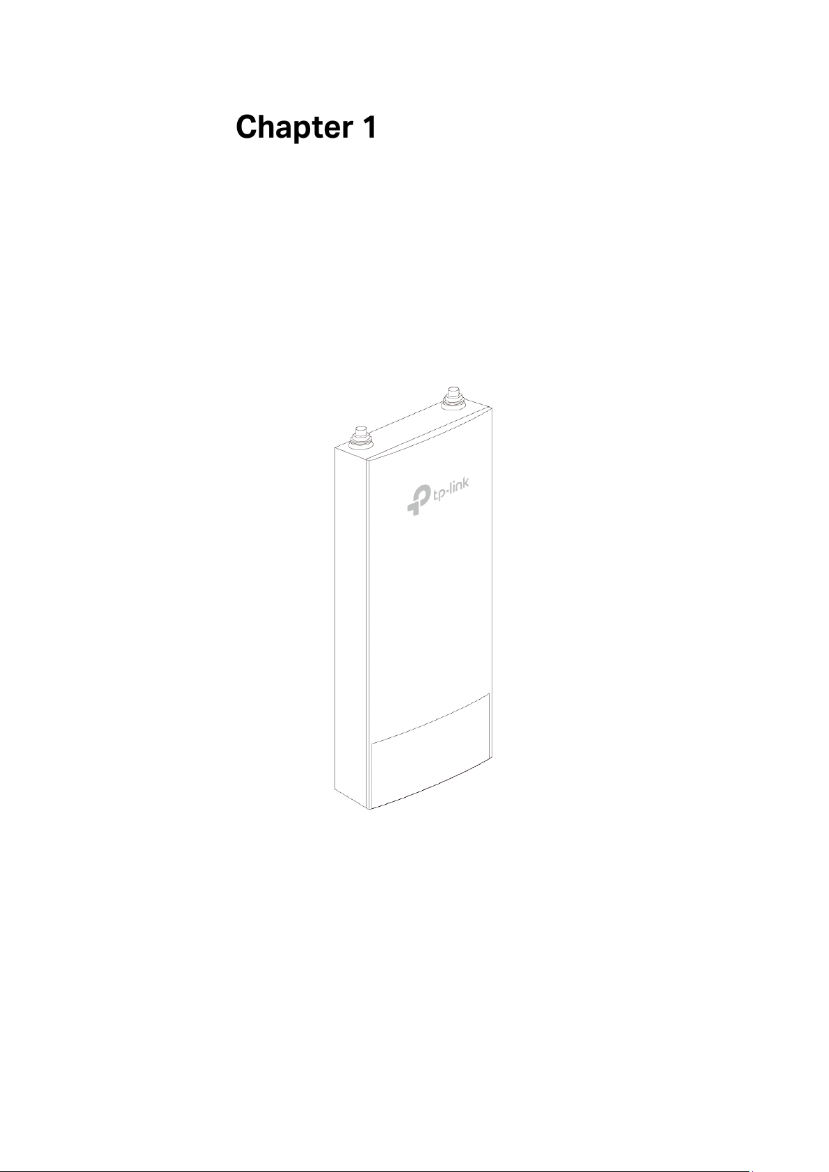
Introduction
CAP300-Outdoor:
Auranet series products provide wireless coverage solutions for small-medium
business. They can either work independently in FAT mode or be centrally managed by
the wireless controller in FIT mode, providing a flexible, richly-functional but easily-
configured enterprise-grade wireless network for small and medium business.
Figure 1-1 Top View of the CAP
2
Page 10

Working Mode
CAPs support two working modes including FIT mode and FAT mode. In FIT mode, APs
can be centrally managed by TP-Link’s wireless controller. The default FIT mode is used
when you want to deploy a large wireless network. The management of every single AP
in the network is complex and complicated. With the wireless controller, you can
centrally manage the mass APs simply in a web browser.
In FAT mode, you can log in to AP’s webpage to manage the AP alone. The FAT mode is
used in a small wireless network. The AP cannot be managed by wireless controller in
FAT mode.
FIT Mode
In the default FIT mode, CAP should be managed by the wireless controller. Please refer
to the Wireless Controller User Guide from our website at www.tp-link.com to learn
more information about configuring and using the CAPs by the controller.
3
Page 11
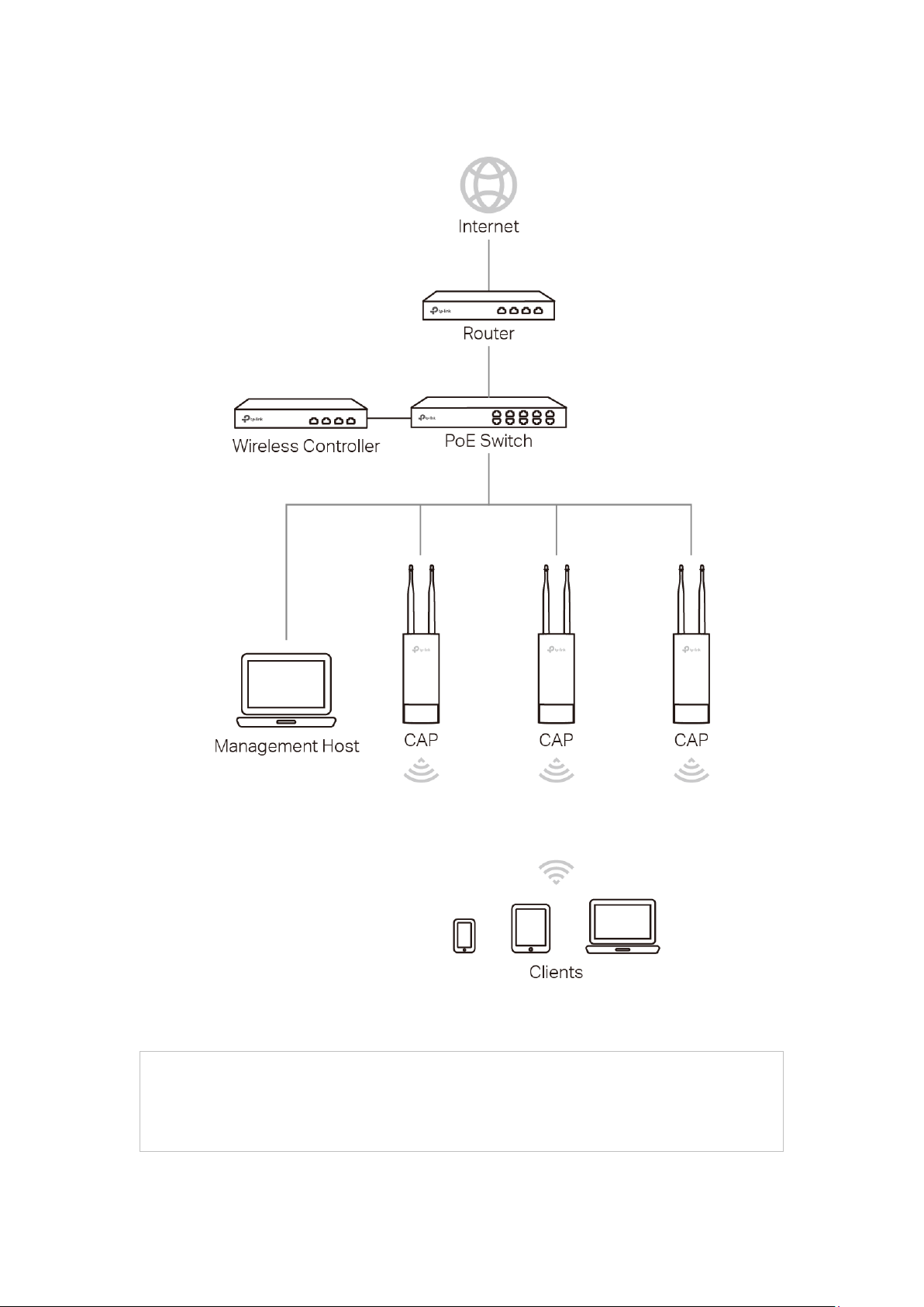
Typical topology in FIT mode:
NOTE:
The IP address of the wireless controller must be reachable for the CAPs in the
network.
Figure 2-1 Typical Topology in FIT Mode
4
Page 12

FAT Mode
In FAT mode, you can log in to AP’s webpage to manage the AP alone. The FAT mode is
used in a small wireless network.
Typical topology in FAT mode:
Figure 2-2 Typical Topology in FIT Mode
5
Page 13

Follow the steps below to log in to the web interface.
NOTE:
to 253). Subnet Mask is 255.255.255.0.
1. Launch a web browser, enter 192.168.0.254 in the address field and press the Enter
key.
To log in to the device, the IP address of your PC should be set in the same subnet
addresses of the device. The IP address is 192.168.0.x (”x” is any number from 1
2. Create a new username and password for login, and then click OK.
Figure 2-3 Login
3. The webpage will be shown as below. Click the menu bar to configure the
corresponding parameters.
6
Page 14

Figure 2-4 Status
TIPS:
Proceed to the following chapters for information on configuring the CAP in FAT mode.
7
Page 15

The
Status
and wireless client of the CAP.
page displays the device information, wireless parameter, wireless service
Status
Figure 3-1 Status Page
Device Information
This section displays the information of hardware version, MAC address, IP address,
system time and running time of the CAP. If you want to modify the IP address of the CAP,
Please refer to AP Management. To modify the system time, please refer to
Setting.
Figure 3-2 Device Information
Time
Wireless Parameter
This section displays the wireless mode, channel bandwidth, channel frequency and
WDS status of the device. Please refer to Advanced Settings
8
to configure the wireless
Page 16

mode, channel bandwidth and channel frequency and refer to WDS Settings to
NOTE:
password here will not change the encryption type.
configure the WDS feature.
Figure 3-3 Wireless Parameter
Wireless Service
In this section, you can check or edit the wireless service information of the CAP.
Figure 3-4 Wireless Service
Click the button to edit the corresponding wireless service entry. You can change
the SSID, Network type and password. Check or uncheck the status box to enable or
disable the wireless service as needed.
Figure 3-5 Wireless
If the wireless network is not encrypted, changing password here will encrypt the network
with WPA-PSK/WPA2-PSK. If the wireless network has been already encrypted, changing
9
Page 17

Wireless Client
The wireless client table displays the information of the connected clients including their
MAC address, connected SSID and the connection time.
Figure 3-6 Wireless Client
10
Page 18

Wireless
Wireless
NOTE:
the CAP.
page consists of Wireless, WDS Settings and Advanced Settings.
Figure 4-1 Wireless Page
If you have made any change of the parameters, please click OK to make the
configuration take effect. There will be a blue bar at the top of the page to remind you to
save the configuration. Click Save when you finish all settings, otherwise all the settings
will be recovered to last saved settings at reboot or power off.
Proceed to the following chapter for information on configuring the wireless network of
Wireless
This section allows you to configure the wireless basic settings, such as SSID, network
type, security mode, and password of each wireless service entry.
11
Page 19

Figure 4-2 Wireless
Click Add to create a new wireless service. Click button to edit the corresponding
wireless service.
SSID: Enter a character string no more than 32 characters to name your
wireless network. We suggest you to set an easy-to-remember SSID
to conveniently identify your wireless network.
Check the box of Enable Broadcast to allow this device to broadcast
its SSID. Therefore, the hosts within its wireless coverage could find
the wireless signals.
Network Type: Select the network type of the wireless network.
Guest Network: The hosts in a guest network cannot communicate
with hosts in other wireless networks.
Office Network: Functions as a normal wireless network.
Security Mode: Select the security mode of wireless network. If all the hosts are
allowed to access the wireless network without password, please
select None. For the safety of wireless network, you are suggested to
encrypt your wireless network. This device provides two security
modes: WPA/WPA2 (Wi-Fi Protected Access) and WPA-PSK/WPA2-
PSK (WPA Pre-Shared Key). WPA-PSK/WPA2-PSK is recommended.
Settings vary in different security modes as the details is in the
following introduction.
AP Isolation: Select this checkbox to enable the AP Isolation feature that allows
you to confine and restrict all wireless devices on your network from
interacting with each other, but still able to access the Internet. This
function will be disabled if WDS is enabled.
12
Page 20

Enable Wireless
ASCII, the length should be between 8 and 63 characters with
sensitive) and common
Network:
Check the box to enable this wireless network, allowing the hosts
connected to the wireless network to communicate with each other.
Security Mode
Following is the detailed introduction of security mode: WPA/WPA2 and WPA-PSK/WPA2-
PSK
.
WPA-PSK/WPA2-PSK
Based on pre-shared key. It is characterized by higher safety and simple settings, which
suits for common households and small business. WPA-PSK has two versions: WPA-
PSK and WPA2-PSK.
Figure 4-3 Security Mode WPA-PSK/WPA2-PSK
Authentication
Type:
Auto: Select WPA or WPA2 automatically based on the wireless
station's capability and request.
WPA-PSK: Pre-shared key of WPA.
WPA2-PSK: Pre-shared key of WPA2.
Encryption: Select the encryption type, including Auto, TKIP, and AES. The default
setting is Auto, which can select TKIP (Temporal Key Integrity Protocol) or
AES (Advanced Encryption Standard) automatically based on the wireless
station's capability and request. AES is more secure than TKIP and TKIP
is not supported in 802.11n mode. It is recommended to select AES as
the encryption type.
PSK Password: Configure the PSK password with ASCII or Hexadecimal characters. For
combination of numbers, letters (casepunctuations. For Hexadecimal, the length should be 64 characters (caseinsensitive, 0-9, a-f, A-F).
Group Key
Update Period:
WPA/WPA2
Specify the group key update period in seconds. The value can be either
0 or 30-8640000 seconds.
13
Page 21

Based on Radius Server, WPA can assign different password for different users and it is
NOTE:
11b/g/n mode, the device may work at a low transmission rate.
much safer than WPA-PSK. However, its maintenance costs much which is only suitable
for enterprise users. At present, WPA has two versions: WPA and WPA2.
Figure 4-4 Security Mode WPA/WPA2
Authentication
Type:
Select one of the following versions:
Auto: Select WPA-PSK or WPA2-PSK automatically based on the
wireless station's capability and request.
WPA: Wi-Fi Protected Access.
WPA2: Version 2 of WPA.
Encryption: Select the encryption type, including Auto, TKIP, and AES. The default
setting is Auto, which can select TKIP (Temporal Key Integrity Protocol)
or AES (Advanced Encryption Standard) automatically based on the
wireless station's capability and request. AES is more secure than TKIP
and TKIP is not supported in 802.11n mode. It is recommended to select
AES as the encryption type.
RADIUS
Enter the IP address/port of the RADIUS server.
Server/Port:
RADIUS
Enter the shared secret of RADIUS server to access the RADIUS server.
Password:
Group Key
Update period:
Specify the group key update period in seconds. The value can be either
0 or 30-8640000 seconds.
Encryption type TKIP is not supported in 802.11n mode. If TKIP is applied in 802.11n mode,
the clients may not be able to access the wireless network of the CAP. If TKIP is applied in
WDS Settings
WDS (Wireless Distribution System) is a communication system among multiple wireless
local area networks established between APs through wireless connection. In this
14
Page 22

system, only data frames with four address fields can be transparently forwarded at the
link layer. In a WDS network, it is necessary that the root AP supports forwarding of data
frames four address fields. If not, only data frames with the ARP/IP/PPPOE protocol can
be forwarded among APs.
Figure 4-5 WDS Settings
Check the box and click OK. The following figure will be shown. Click Yes to enable the
WDS feature.
There are two ways to select the root AP. Scan or manually enter the parameters.
Scan
Click the Scan button, the AP list will be shown as below. Select the desired root AP to
bridge in the AP list.
Figure 4-6 AP List
After selecting the desired root AP, the WDS settings page will be shown as below. If the
root AP is encrypted, you should enter the PSK password manually. Click OK to finish the
settings.
15
Page 23

Figure 4-7 WDS Settings
This option should be chosen according to the AP's security
Manually
You should manually enter the parameters of the root AP. Click OK to finish the settings.
WDS: Check the box to enable WDS feature.
SSID:
BSSID: The BSSID of the AP your device is going to connect to as a client.
Security Mode:
The SSID of the AP your device is going to connect to as a client.
configuration. It is recommended that the security type is the same as
your AP's security type.
Select the encryption type, including None and WPA-PSK/WPA2-PSK.
The default setting is None. Please refer to Security Mode
for details.
Advanced Settings
You can configure the advanced settings in this section. Improper configuration would
degrade the CAP’s wireless performance. With no special requirement, it is
recommended to keep the default settings.
Figure 4-8 Advanced Settings
Wireless Mode: Select the protocol standard for the wireless network.
16
Page 24

It is recommended to select 802.11b/g/n, in which way clients supporting
proper bandwidth
, so the AP will choose the best channel
any one of these modes can access your wireless network.
Channel
Bandwidth:
Select the channel bandwidth of this device including 20MHz and 40MHz.
The default setting is Auto, which will select the
automatically according to the network need.
According to IEEE 802.11n standard, using a higher bandwidth can
increase wireless throughput. However, users may choose lower
bandwidth due to the following reasons:
1. To increase the available number of channels within the limited total
bandwidth.
2. To avoid interference from overlapping channels occupied by other
devices in the environment.
3. Lower bandwidth can concentrate higher transmit power, increasing
stability of wireless links over long distances.
Channel: This field determines which operating frequency will be used. The default
channel is set to Auto
automatically. It is not necessary to change the wireless channel unless
you notice interference problems with another nearby access point.
Transmit
Power:
You can use the slider or manually enter the transmit power value. The
maximum transmit power may vary among different countries or regions.
SSID Isolation: With this option enabled, the hosts connected to different wireless
networks cannot communicate with each other.
Beacon
Interval:
Beacons are transmitted periodically by the device to announce the
presence of a wireless network for the clients.
Enter a time interval between 40 and 1000 in milliseconds to determine
the duration between beacon packets that are transmitted periodically by
the device to synchronize the wireless network. The default is 100
milliseconds.
Maximum
Specify the maximum users that allowed to connect to the CAP.
Users:
Forbid stations
with a signal
strength lower
than ( ) dBm
from accessing
the AP:
Enable or disable the access rules.
Set the minimum signal strength for a new client to be allowed to access
the network. Values from -95 to 0 dBm are valid. The default value is -75
dBm. It is recommended the maximum number is less than -40 dBm.
When clients attempt to connect to the AP with lower signal strength than
the threshold value (for example due to obstacles or long distances), they
will be denied access to the AP.
17
Page 25

Discard
stations with a
signal strength
lower than ( )
dBm:
Enable or disable the discard rules.
Set the minimum signal strength in which the AP will discard a connected
client. Values from -95 to 0 dBm are valid. The default value is -75dBm. It
is recommended the maximum number is less than -40 dBm. When the
signal strength of the connected client is lower than the threshold value
(for example due to obstacles or long distances), the client will be
discarded by the AP.
18
Page 26

Network
Network
On
If you have made any change of the parameters, please click OK to make the
configuration take effect. There will be a blue bar at the top of the page to remind you to
page, you can configure the wireless MAC filtering rule and set the VLANs.
Figure 5-1 Network Page
save the configuration. Click Save when you finish all settings, otherwise all the settings
will be recovered to last saved settings at reboot or power off.
Wireless MAC Filtering
Wireless MAC Filtering feature uses MAC addresses to determine whether one host can
access the wireless network or not. Thereby it can effectively control the user access in
the wireless network.
Figure 5-2 Wireless MAC Filtering
Wireless MAC
Filtering:
Click Add to create a wireless MAC filtering entry. The following page will be shown.
Check the box and select one or more wireless networks to enable the
wireless MAC filtering on the selected wireless network(s). With MAC
filtering enabled, only MAC addresses listed in the rule list can be
connected to the corresponding wireless network.
19
Page 27

Figure 5-3 Filtering Rule
MAC Address: Enter the MAC address of the client.
Effective Range: Select the wireless network that allows the client to access.
Description: Specify a description for the entry to make it easier to search for and
manage.
Click button to modify the corresponding entry and click button to delete
the selected entry.
VLAN Settings
In this section, all the wireless network will be listed here.
Figure 5-4 VLAN List
The CAP can add different VLAN tag to the clients which connect to the corresponding
wireless network. The clients with different VLAN ID cannot directly communicate with
each other. Click button to specify the VLAN ID for the corresponding network.
Figure 5-5 VLAN Settings
VLAN: Check the box to enable the VLAN feature.
VLAN ID: Specify a VLAN ID for the wireless network.
20
Page 28

System
System
user account, system log, time setting, and realize functions including reboot, reset,
backup, restore, firmware upgrade and ping watch dog.
page is mainly used to configure some basic information like AP management,
Figure 6-1 System Page
If you have made any change of the parameters, please click OK to make the
configuration take effect. There will be a blue bar at the top of the page to remind you to
save the configuration. Click Save when you finish all settings, otherwise all the settings
will be recovered to last saved settings at reboot or power off.
21
Page 29

AP Management
You can change the IP address, mask, default gateway, web service port and web
session timeout of the CAP and enable the manage VLAN.
Figure 6-2 AP Management Page
IP Address: Set the IP address through which the hosts in the LAN can visit the
CAP. The default setting is 192.168.0.254. You can change the IP
according to the network need.
Mask: Set the mask of CAP. The default setting is 255.255.255.0. You can
change it according to the network need.
Default Gateway: Set the default gateway of CAP. The default setting is 255.255.255.0.
You can change it according to the network need.
Manage VLAN: Check the box to enable the manage VLAN. Specify the Manage
VLAN ID. The valid values are from 1 to 4094.
Manage VLAN provides a safer way for you to manage the CAPs.
With it enabled, only the hosts in the manage VLAN can log in to the
CAP’s webpage. Since most hosts cannot process VLAN TAGs, you
should connect the management host to the network via a switch.
Configure VLAN settings for the switches on the network to ensure
the communication between the host and the CAP in the manage
VLAN.
WEB Service
Port:
Set the Web service port for the CAP.
22
Page 30

Web Session
Timeout:
Set the session timeout for the webpage. When you log in to the
CAP’s webpage, if there is no operation during the set time, the
webpage will be logged out automatically.
Account
You can change the username and password to protect your device from unauthorized
login.
Figure 6-3 Account Page
Current User
Name/Password:
New User
Name/Password:
Confirm the
Password:
Enter the current user name and password of the admin account to
get the permission of modification.
Enter a new user name and password for the admin account. Both
values are case-sensitive, up to 64 characters and with no space.
Enter the new password again.
System Log
Check the system log in this section.
23
Page 31

Figure 6-4 System Log
MM/DD. For example, for
Check Log: Click Open to check the system log.
Download Log: Click Download to download the system log.
Send To Server/
Server Address:
Check the box to enable the function. If you want to check the system
log in a specified host, please install a system log server and enter the
server IP in this field. Click OK, then the AP will send the system log to
the specified IP address.
Time Setting
System time represents the device system’s notion of the passing of time. System time
is the standard time for Scheduler and other time-based functions. You can manually set
the system time, configure the system to acquire its time settings from a preconfigured
NTP server.
Figure 6-5 Time Settings
Time zone: Select your local time zone from the drop-down list.
Date: Set the current date, in format YYYY/
November 25, 2014, enter 2014/11/25 in the field.
24
Page 32

Time: Specify the device’s time. Select the number from the drop-down
list in time format HH/MM/SS.
NTP Server I/NTP
Server II:
Please input the primary NTP sever address and an alternative NTP
server address.
Configuration Management
In this section, you can backup, restore, reset or reboot your CAP.
Figure 6-6 Configuration Management
Backup: Click Backup to save a copy of your current settings. Please save
your copy in a secure file location. It is recommended to back up the
settings before you change the configurations and upgrade the
firmware.
Restore: Click Browse to locate and select the backup file, then click Restore
to import the file to recover the configurations.
Factory Restore: Click Reset to restore your device to its factory default settings.
Reboot: Click Reboot to reboot your device. Do NOT power off your device
while it is rebooting.
Firmware Upgrade
Please log in http://www.tp-link.com/ to download the latest system file. Click Browse to
locate and select the firmware file. Click Upload to upload the file to upgrade.
Figure 6-7 Firmware Upgrade
After the firmware is uploaded, the page below will be shown. If you want to save the
current settings, please click Save Configuration. If you want to restore the device to
factory defaults please click Restore.
25
Page 33

Figure 6-8 Firmware Upgrade
Hardware Version: Display the current hardware version.
Firmware Version: Display the current Firmware version.
Firmware Upgrade: Click Browse to locate and select the firmware file. Click Upload to
upload the file to upgrade. Do NOT power off your device while it is
upgrading.
Ping Watch Dog
Ping Watch Dog sets the device to continuously ping a user-defined IP address (it can
be the Internet gateway, for example) to check the network connectivity. If there is a
connection failure then the device will automatically reboot.
Ping Watch Dog is dedicated to continuously monitoring the connectivity to a specific
host using the Ping tool. The Ping tool sends ICMP echo request packets to the target
host and listens for ICMP echo response. If the defined number of replies is not received,
the tool reboots the device.
Figure 6-9 Ping Watch Dog
Ping Watch Dog: Check the box to enable the feature.
Destination IP
Address:
Ping Interval: Enter the time interval (in seconds) between two successive ping
Specify the IP address of the target host to which the Ping Watch
Dog Utility will send ping packets.
packets. The default value is 300 seconds.
26
Page 34

Start-up Delay: Enter the initial time delay (in seconds) from device startup to the
first ICMP echo requests sent by Ping Watch Dog. The default value
is 300 seconds.
The Startup Delay value should be at least 60 seconds as the
device’s initialization takes a considerable amount of time.
Lost Packets Count: Enter the fail count of ICMP echo request. If the device sends the
specified count of ICMP echo requests to the host and none of the
corresponding ICMP echo response packets is received, Ping
Watch Dog will reboot the device. The default value is 3.
27
 Loading...