

Page 1

User Guide
Dual Band Gigabit VoIP VDSL/ADSL Modem Router
Archer VR1600v
1910012222 REV1.0.0
Page 2

Contents
About This Guide . . . . . . . . . . . . . . . . . . . . . . . . . . . . . . . . . . . . . . . . . . . . . . . . . . . . .1
Chapter 1. Get to Know Your Modem Router. . . . . . . . . . . . . . . . . . . . . . . . . . 2
1. 1. Product Overview. . . . . . . . . . . . . . . . . . . . . . . . . . . . . . . . . . . . . . . . . . . . . . . . . . . . . . . . . . . . 3
1. 2. Physical Appearance . . . . . . . . . . . . . . . . . . . . . . . . . . . . . . . . . . . . . . . . . . . . . . . . . . . . . . . . 3
1. 2. 1. LED. . . . . . . . . . . . . . . . . . . . . . . . . . . . . . . . . . . . . . . . . . . . . . . . . . . . . . . . . . . . . . . . 3
1. 2. 2. Ports . . . . . . . . . . . . . . . . . . . . . . . . . . . . . . . . . . . . . . . . . . . . . . . . . . . . . . . . . . . . . . 5
1. 2. 3. Buttons. . . . . . . . . . . . . . . . . . . . . . . . . . . . . . . . . . . . . . . . . . . . . . . . . . . . . . . . . . . . 5
Chapter 2. Connect the Hardware . . . . . . . . . . . . . . . . . . . . . . . . . . . . . . . . . . . . 7
2. 1. Position Your Modem Router . . . . . . . . . . . . . . . . . . . . . . . . . . . . . . . . . . . . . . . . . . . . . . . . . 8
2. 2. Connect Your Modem Router . . . . . . . . . . . . . . . . . . . . . . . . . . . . . . . . . . . . . . . . . . . . . . . . 8
Chapter 3. Log In to Your Modem Router . . . . . . . . . . . . . . . . . . . . . . . . . . . 11
Chapter 4. Set Up Internet Connections . . . . . . . . . . . . . . . . . . . . . . . . . . . . 13
4. 1. Use Quick Setup Wizard . . . . . . . . . . . . . . . . . . . . . . . . . . . . . . . . . . . . . . . . . . . . . . . . . . . . 14
4. 2. Manually Set Up an Internet Connection . . . . . . . . . . . . . . . . . . . . . . . . . . . . . . . . . . . . 14
4. 3. Test Internet Connectivity . . . . . . . . . . . . . . . . . . . . . . . . . . . . . . . . . . . . . . . . . . . . . . . . . . 14
4. 4. Set Up an IPv6 Connection . . . . . . . . . . . . . . . . . . . . . . . . . . . . . . . . . . . . . . . . . . . . . . . . . 15
Chapter 5. VoIP . . . . . . . . . . . . . . . . . . . . . . . . . . . . . . . . . . . . . . . . . . . . . . . . . . . . 17
5. 1. Connecting the Telephone . . . . . . . . . . . . . . . . . . . . . . . . . . . . . . . . . . . . . . . . . . . . . . . . . . 18
5. 2. Entering Telephone Information . . . . . . . . . . . . . . . . . . . . . . . . . . . . . . . . . . . . . . . . . . . . . 18
5. 3. Telephone Book . . . . . . . . . . . . . . . . . . . . . . . . . . . . . . . . . . . . . . . . . . . . . . . . . . . . . . . . . . . . 20
5. 3. 1. Telephone Book . . . . . . . . . . . . . . . . . . . . . . . . . . . . . . . . . . . . . . . . . . . . . . . . . . 20
5. 3. 2. Emergency Calls. . . . . . . . . . . . . . . . . . . . . . . . . . . . . . . . . . . . . . . . . . . . . . . . . . 21
5. 4. Telephony Devices Management. . . . . . . . . . . . . . . . . . . . . . . . . . . . . . . . . . . . . . . . . . . . 22
5. 5. Call Log . . . . . . . . . . . . . . . . . . . . . . . . . . . . . . . . . . . . . . . . . . . . . . . . . . . . . . . . . . . . . . . . . . . . 24
5. 6. Calling via Which Number . . . . . . . . . . . . . . . . . . . . . . . . . . . . . . . . . . . . . . . . . . . . . . . . . . . 24
5. 7. Call Blocks. . . . . . . . . . . . . . . . . . . . . . . . . . . . . . . . . . . . . . . . . . . . . . . . . . . . . . . . . . . . . . . . . . 25
5. 7. 1. Do Not Disturb. . . . . . . . . . . . . . . . . . . . . . . . . . . . . . . . . . . . . . . . . . . . . . . . . . . . 25
5. 7. 2. Blocking Certain Calls . . . . . . . . . . . . . . . . . . . . . . . . . . . . . . . . . . . . . . . . . . . . 26
5. 7. 3. Prevent from Dialing . . . . . . . . . . . . . . . . . . . . . . . . . . . . . . . . . . . . . . . . . . . . . . 27
5. 8. Forwarding Calls. . . . . . . . . . . . . . . . . . . . . . . . . . . . . . . . . . . . . . . . . . . . . . . . . . . . . . . . . . . . 27
Page 3

5. 9. Voice Mail . . . . . . . . . . . . . . . . . . . . . . . . . . . . . . . . . . . . . . . . . . . . . . . . . . . . . . . . . . . . . . . . . . 28
Chapter 6. USB Settings. . . . . . . . . . . . . . . . . . . . . . . . . . . . . . . . . . . . . . . . . . . . 31
6. 1. Access the USB Storage Device . . . . . . . . . . . . . . . . . . . . . . . . . . . . . . . . . . . . . . . . . . . . 32
6. 1. 1. Access the USB Device Locally . . . . . . . . . . . . . . . . . . . . . . . . . . . . . . . . . . . 32
6. 1. 2. Access the USB Device Remotely . . . . . . . . . . . . . . . . . . . . . . . . . . . . . . . . . 34
6. 1. 3. Customize the Access Settings . . . . . . . . . . . . . . . . . . . . . . . . . . . . . . . . . . . 35
6. 2. Media Sharing . . . . . . . . . . . . . . . . . . . . . . . . . . . . . . . . . . . . . . . . . . . . . . . . . . . . . . . . . . . . . . 38
6. 3. 3G/4G Settings . . . . . . . . . . . . . . . . . . . . . . . . . . . . . . . . . . . . . . . . . . . . . . . . . . . . . . . . . . . . . 39
6. 3. 1. As a Backup Solution for Internet Access . . . . . . . . . . . . . . . . . . . . . . . . . 40
Chapter 7. Parental Controls . . . . . . . . . . . . . . . . . . . . . . . . . . . . . . . . . . . . . . . 42
Chapter 8. Network Security . . . . . . . . . . . . . . . . . . . . . . . . . . . . . . . . . . . . . . . 46
8. 1. Firewall & DoS Protection . . . . . . . . . . . . . . . . . . . . . . . . . . . . . . . . . . . . . . . . . . . . . . . . . . . 47
8. 2. Service Filtering . . . . . . . . . . . . . . . . . . . . . . . . . . . . . . . . . . . . . . . . . . . . . . . . . . . . . . . . . . . . 48
8. 3. Access Control . . . . . . . . . . . . . . . . . . . . . . . . . . . . . . . . . . . . . . . . . . . . . . . . . . . . . . . . . . . . . 49
8. 4. IP & MAC Binding . . . . . . . . . . . . . . . . . . . . . . . . . . . . . . . . . . . . . . . . . . . . . . . . . . . . . . . . . . . 51
Chapter 9. NAT Forwarding. . . . . . . . . . . . . . . . . . . . . . . . . . . . . . . . . . . . . . . . . 53
9. 1. Translate Address and Port by ALG. . . . . . . . . . . . . . . . . . . . . . . . . . . . . . . . . . . . . . . . . . 54
9. 2. Share Local Resources in the Internet by Virtual Server. . . . . . . . . . . . . . . . . . . . . . 55
9. 3. Open Ports Dynamically by Port Triggering . . . . . . . . . . . . . . . . . . . . . . . . . . . . . . . . . . 56
9. 4. Make Applications Free from Port Restriction by DMZ . . . . . . . . . . . . . . . . . . . . . . . 57
9. 5. Make Xbox Online Games Run Smoothly by UPnP . . . . . . . . . . . . . . . . . . . . . . . . . . . 58
Chapter 10. VPN Server . . . . . . . . . . . . . . . . . . . . . . . . . . . . . . . . . . . . . . . . . . . . . 60
10. 1. Use OpenVPN to Access Your Home Network . . . . . . . . . . . . . . . . . . . . . . . . . . . . . . . 61
10. 2. Use PPTP VPN to Access Your Home Network . . . . . . . . . . . . . . . . . . . . . . . . . . . . . . 62
10. 3. Use IPSec VPN to Access Your Home Network . . . . . . . . . . . . . . . . . . . . . . . . . . . . . . 66
Chapter 11. Specify Your Network Settings. . . . . . . . . . . . . . . . . . . . . . . . . . 69
11. 1. LAN Settings . . . . . . . . . . . . . . . . . . . . . . . . . . . . . . . . . . . . . . . . . . . . . . . . . . . . . . . . . . . . . . . 70
11. 1. 1. Change the LAN IP Address. . . . . . . . . . . . . . . . . . . . . . . . . . . . . . . . . . . . . . . 70
11. 1. 2. Use the Modem Router as a DHCP Server. . . . . . . . . . . . . . . . . . . . . . . . . 71
11. 1. 3. Reserve LAN IP Addresses. . . . . . . . . . . . . . . . . . . . . . . . . . . . . . . . . . . . . . . . 72
11. 2. IPv6 LAN Settings . . . . . . . . . . . . . . . . . . . . . . . . . . . . . . . . . . . . . . . . . . . . . . . . . . . . . . . . . . 72
11. 2. 1. Configure the RADVD Address Type . . . . . . . . . . . . . . . . . . . . . . . . . . . . . . 73
Page 4

11. 2. 2. Configure the DHCPv6 Server Address Type . . . . . . . . . . . . . . . . . . . . . . 73
11. 3. Wireless Settings . . . . . . . . . . . . . . . . . . . . . . . . . . . . . . . . . . . . . . . . . . . . . . . . . . . . . . . . . . . 74
11. 3. 1. Specify Basic Wireless Settings. . . . . . . . . . . . . . . . . . . . . . . . . . . . . . . . . . . 74
11. 3. 2. Use WPS for Wireless Connection . . . . . . . . . . . . . . . . . . . . . . . . . . . . . . . . 76
11. 3. 3. Schedule Your Wireless Function . . . . . . . . . . . . . . . . . . . . . . . . . . . . . . . . . 78
11. 3. 4. View Wireless Information . . . . . . . . . . . . . . . . . . . . . . . . . . . . . . . . . . . . . . . . 79
11. 3. 5. Advanced Wireless Settings . . . . . . . . . . . . . . . . . . . . . . . . . . . . . . . . . . . . . . 79
11. 4. Set Up a Dynamic DNS Service Account . . . . . . . . . . . . . . . . . . . . . . . . . . . . . . . . . . . . 81
11. 5. Interface Grouping. . . . . . . . . . . . . . . . . . . . . . . . . . . . . . . . . . . . . . . . . . . . . . . . . . . . . . . . . . 81
11. 6. Create Static Routes. . . . . . . . . . . . . . . . . . . . . . . . . . . . . . . . . . . . . . . . . . . . . . . . . . . . . . . . 83
11. 7. Set Up the IPv6 Tunnel . . . . . . . . . . . . . . . . . . . . . . . . . . . . . . . . . . . . . . . . . . . . . . . . . . . . . . 85
11. 7. 1. Use the Public IPv6 Tunnel Service-6to4 . . . . . . . . . . . . . . . . . . . . . . . . . . 85
11. 7. 2. Specify the 6rd Tunnel with Parameters Provided by Your ISP . . . . . . 86
Chapter 12. Administrate Your Network . . . . . . . . . . . . . . . . . . . . . . . . . . . . . 88
12. 1. Set System Time . . . . . . . . . . . . . . . . . . . . . . . . . . . . . . . . . . . . . . . . . . . . . . . . . . . . . . . . . . . 89
12. 2. Update the Firmware. . . . . . . . . . . . . . . . . . . . . . . . . . . . . . . . . . . . . . . . . . . . . . . . . . . . . . . . 90
12. 2. 1. Local Upgrade . . . . . . . . . . . . . . . . . . . . . . . . . . . . . . . . . . . . . . . . . . . . . . . . . . . . 90
12. 3. Back up and Restore Configuration Settings . . . . . . . . . . . . . . . . . . . . . . . . . . . . . . . . 91
12. 4. Change the Administrator Account. . . . . . . . . . . . . . . . . . . . . . . . . . . . . . . . . . . . . . . . . . 91
12. 5. Local Management . . . . . . . . . . . . . . . . . . . . . . . . . . . . . . . . . . . . . . . . . . . . . . . . . . . . . . . . . 92
12. 6. Remote Management. . . . . . . . . . . . . . . . . . . . . . . . . . . . . . . . . . . . . . . . . . . . . . . . . . . . . . . 93
12. 7. System Log. . . . . . . . . . . . . . . . . . . . . . . . . . . . . . . . . . . . . . . . . . . . . . . . . . . . . . . . . . . . . . . . . 94
12. 8. CWMP Settings. . . . . . . . . . . . . . . . . . . . . . . . . . . . . . . . . . . . . . . . . . . . . . . . . . . . . . . . . . . . . 95
12. 9. SNMP Settings . . . . . . . . . . . . . . . . . . . . . . . . . . . . . . . . . . . . . . . . . . . . . . . . . . . . . . . . . . . . . 97
Appendix: Troubleshooting . . . . . . . . . . . . . . . . . . . . . . . . . . . . . . . . . . . . . . . . . 99
Page 5
About This Guide
This guide is a complement to Quick Installation Guide. The Quick Installation Guide
provides instructions for quick Internet setup, while this guide contains details of each
function and demonstrates how to configure them in typical scenarios.
When using this guide, please notice that features of the router may vary slightly
depending on the model and software version you have, and on your location, language,
and Internet service provider. All images, parameters and descriptions documented in
this guide are used for demonstration only.
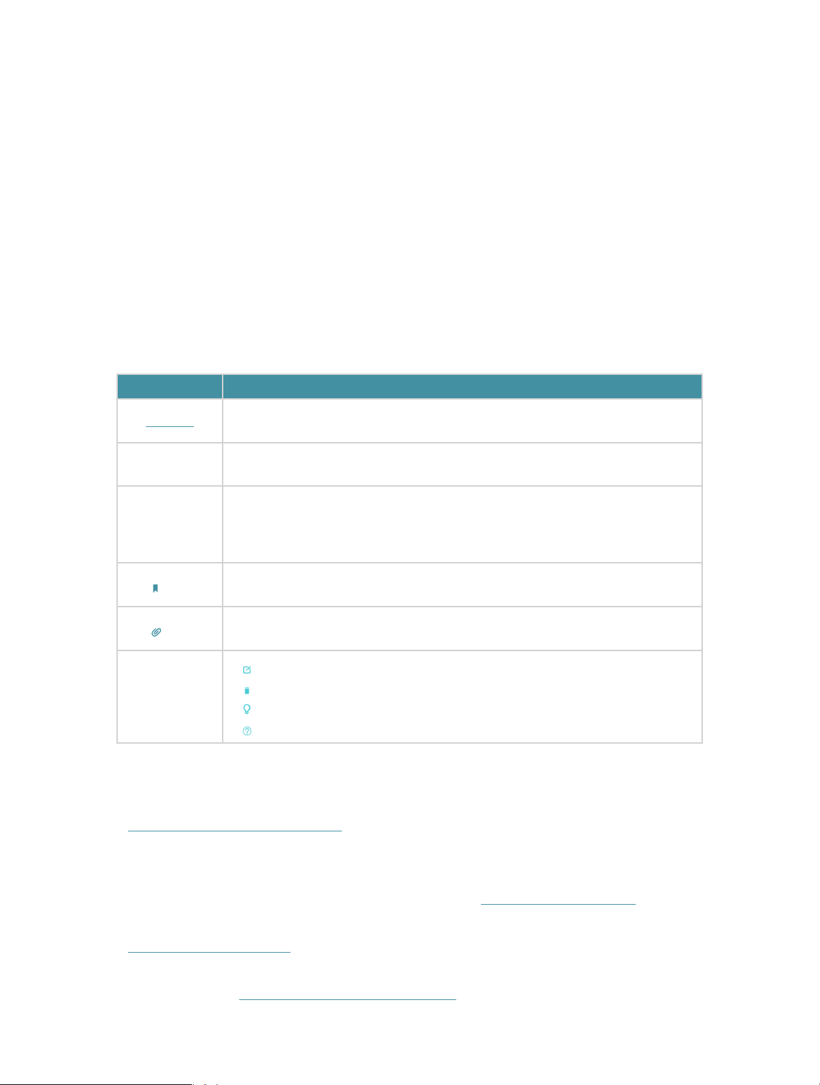
Conventions
In this guide, the following conventions are used:
Convention
Underline
Teal
>
Note:
Tips:
symbols on
the web page
More Info
Description
Hyperlinks are in teal and underlined. You can click to redirect to a website
or a specific section.
Key information appears in teal, including management page text such as
menus, items, buttons and so on.
The menu structures to show the path to load the corresponding page.
For example, Advanced > Wireless > Wireless Settings means the Wireless
Settings function page is under the Wireless menu that is located in the
Advanced tab.
Ignoring this type of note might result in a malfunction or damage to the
device.
Indicates important information that helps you make better use of your
device.
• click to edit the corresponding entry.
• click to delete the corresponding entry.
• click to enable or disable the corresponding entry.
• click to view more information about items on the page.
• The latest firmware and management app are available from Download Center at
http://www.tp-link.com/support.
• The Quick Installation Guide (QIG) can be found where you find this guide or inside the
product package.
• Specifications can be found on the product page at http://www.tp-link.com.
• A Technical Support Forum is provided for you to discuss our products at
http://forum.tp-link.com.
• Our Technical Support contact information can be found at the Contact Technical
Support page at http://www.tp-link.com/support.
1
Page 6

Chapter 1
Get to Know Your Modem Router
This chapter introduces what the modem router can do and shows its main features
and appearance.
It contains the following sections:
• Product Overview
• Physical Appearance
Page 7
Chapter 1
Get to Know Your Modem Router
1. 1. Product Overview
TP-Link’s Modem Router is a combined wired/wireless network connection device
with integrated wireless router and DSL modem, reducing hassle of configuration and
saving space.
With DSL, WAN, and USB ports, the modem router is compatible with DSL connections
and 3G/4G USB dongles.
With Ethernet ports and antennas, the modem router provides wired and wireless
access for multiple computers and mobile devices.
With various features and functions, the modem router is the perfect hub of your home
or business network.
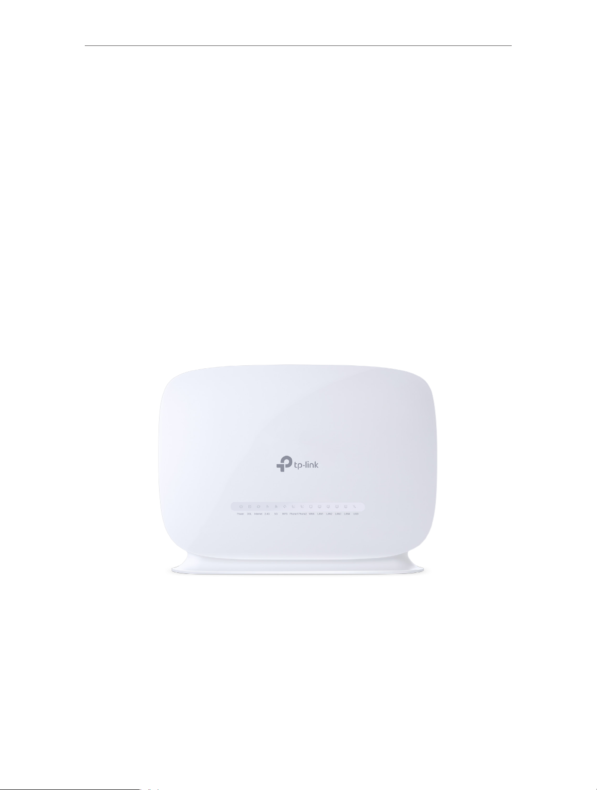
1. 2. Physical Appearance
1. 2. 1. LED
The modem router’s LEDs are located on the front panel. You can check the modem
router’s working status by following the LED Explanation table.
3
Page 8
Chapter 1
Get to Know Your Modem Router
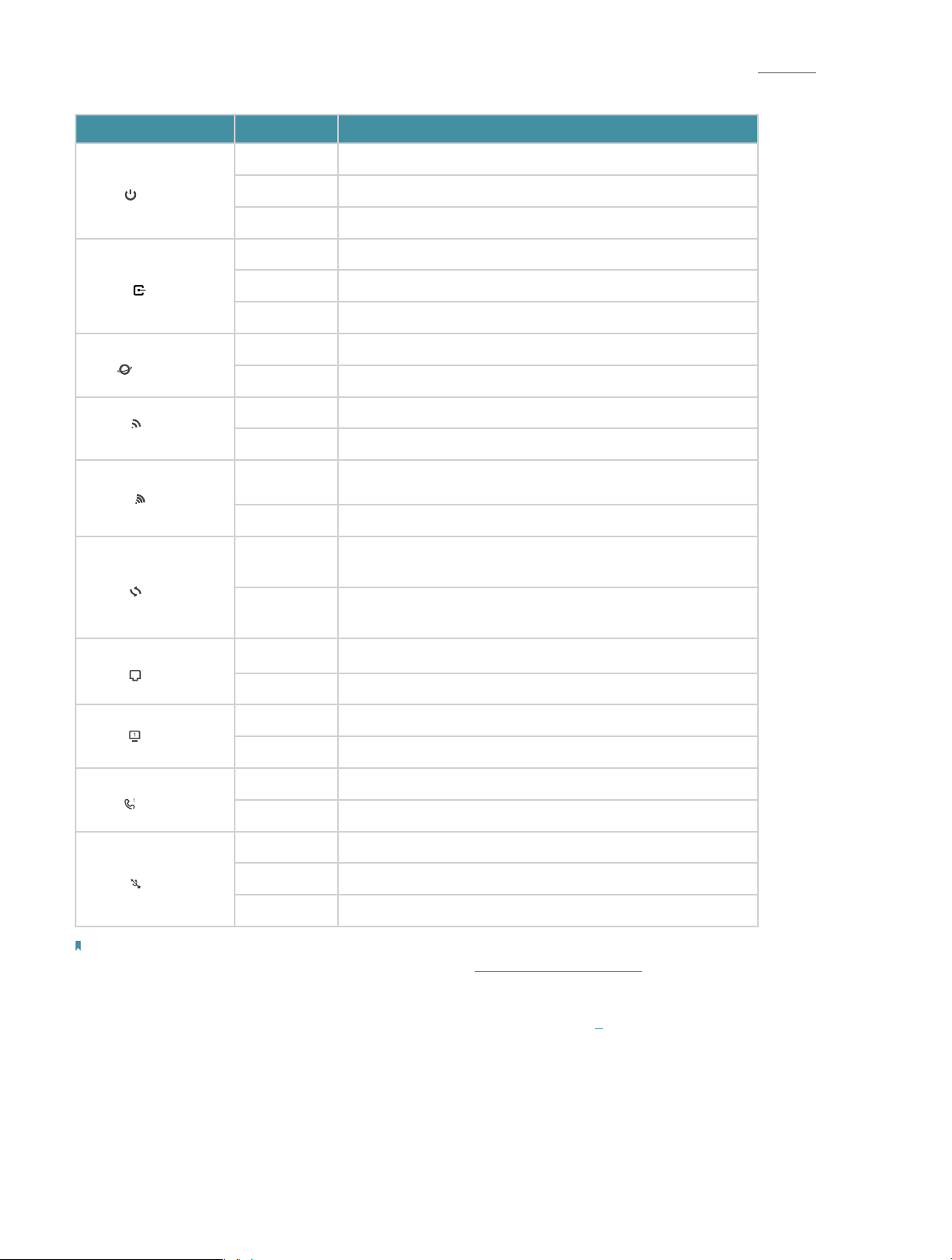
LED Explanation
Name Status
On Power is on.
Power
DSL
Internet
2.4G
5G
WPS
Flashing The modem is booting up.
Off Power is off.
On DSL synchronization is complete.
Flashing DSL synchronization is in progress.
Off DSL synchronization failed.
On Internet connection is available.
Off No internet connection or the connection type is Bridge.
On The 2.4GHz wireless radio band is enabled.
Off The 2.4GHz wireless radio band is disabled.
On The 5GHz wireless radio band is enabled.
Off The 5GHz wireless radio band is disabled.
On/Off
Flashing
Indication
Turns on when a WPS synchronization is established and
automatically turns off about five minutes later.
A wireless device is trying to connect to the network via
WPS. This process may take up to 2 minutes.
On A device is connected to the WAN port.
WAN
Off No device is connected to the WAN port.
On A device is connected to the LAN port.
LAN
Off No device is connected to the LAN port.
On The phone is off-hook.
Phone
Off The phone is on-hook.
On The USB device is ready to use.
USB
Flashing A new USB device is being identified.
Off No USB device is plugged into the USB port.
Note:
1. If the DSL LED is off, please check your Internet connection first. Refer to Connect Your Modem Router for more information
about how to make Internet connection correctly. If you have already made a right connection, please contact your ISP to make
sure your Internet service is available now.
2. If the Internet LED is off, please check your DSL LED first. If your DSL LED is also off, please refer to 1. If your DSL LED is ON, please
check your Internet configuration. You may need to check this part of information with your ISP and make sure everything have
been input correctly.
4
Page 9
Chapter 1
Get to Know Your Modem Router
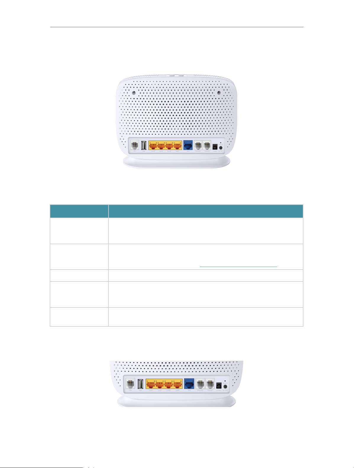
1. 2. 2. Ports
The modem router’s back panel shows the connection ports. Refer to the following for
detailed instructions.
Item
Phone1/Phone2
DSL
USB For connecting to a USB storage device.
LAN1, LAN2, LAN3,
LAN4/WAN
POWER
1. 2. 3. Buttons
Description
For connecting your analog phone to the modem router. Note that
you can only connect to two ports (one to a Phone1 and the other to a
Phone2) at most.
For connecting the modem router to the Internet. Connect the port to
the splitter or directly connect the port to the phone jack via a phone
cable. For details, please refer to Connect Your Modem Router.
For connecting the modem router to your PC or other Ethernet network
devices. In wireless router mode you will be able to connect to VDSL/
ADSL devices.
For connecting the modem router to power socket via the provided
power adapter.
The modem router’s back panel and top panel show the buttons. Refer to the following
for detailed instructions.
5
Page 10

Chapter 1
Get to Know Your Modem Router
Item
ON/OFF The switch for the power. Press it to power on or off the modem router.
RESET
WiFi Press for 1 second to turn both 2.4GHz and 5GHz Wi-Fi on or off.
WPS Press for 5 seconds to start a WPS synchronization.
Press and hold down for 10 seconds to reset the modem router into
factory default settings.
Description
6
Page 11

Chapter 2
Connect the Hardware
This chapter contains the following sections:
• Position Your Modem Router
• Connect Your Modem Router
Page 12
Chapter 2
Phone (Optional)
Phone Cable
DSL Splitter
Connect the Hardware
2. 1. Position Your Modem Router
With the modem router, you can access your network from anywhere within the
wireless network coverage. However, the wireless signal strength and coverage varies
depending on the actual environment where your modem router is in. Many obstacles
may limit the range of the wireless signal, for example, concrete structures, thick walls.
For your security and best Wi-Fi performance, please:
• Do Not locate the modem router in the place where it will be exposed to moisture or
excessive heat.
• Keep away from the strong electromagnetic radiation and the device of
electromagnetic sensitive.
• Place the modem router in a location where it can be connected to the various devices
as well as to a power source.
• Make sure the cables and power cord are safely placed out of the way so they do not
create a tripping hazard.
Tips: The modem router can be placed on a shelf or desktop.
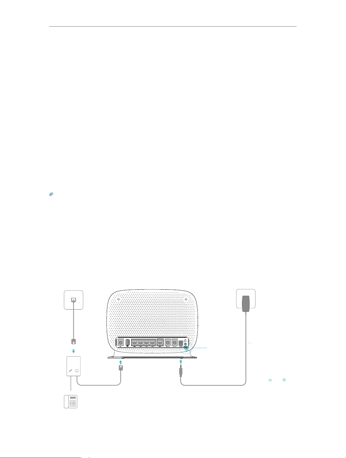
2. 2. Connect Your Modem Router
Follow the steps below to connect your modem router.
1. Connect the DSL line and power adapter. The electrical outlet shall be installed
near the device and shall be easily accessible.
Power Adapter
Power On DSL On
Phone Cable
Phone Jack
LINE
PHONE MODEM
1
Push in to turn on
3
the modem router.
2
8
Page 13

Chapter 2
Connections are available
Wireless Network Connection
Connect the Hardware
2. Connect your computer to the modem router.
Method 1: Wired
Connect your computer’s Ethernet port to the LAN port on the modem router via the
Ethernet cable.
Ethernet Cable
Method 2: Wirelessly
Use the default SSID (Wireless Network Name) and Wireless Password printed on the
product label of the modem router to connect wirelessly.
Computer Smart Device
Wi-Fi
TP-LINK_XXXX
TP-LINK_XXXX_5G
√
Connect automatically Connect
< Settings
Wi-Fi
CHOOSE A NETWORK...
TP-LINK_XXXX
TP-LINK_XXXX_5G
Other...
Method 3: Use the WPS button
Wireless devices that support WPS, including Android phones, tablets, most USB
network cards, can be connected to your router through this method. (WPS is not
supported by iOS devices.)
Note:
The WPS function cannot be configured if the wireless function of the router is disabled. Also, the WPS function will be
disabled if your wireless encryption is WEP. Please make sure the wireless function is enabled and is configured with the
appropriate encryption before configuring the WPS.
1 ) Tap the WPS icon on the device’s screen.
2 ) Immediately press the WPS button on your modem router.
3 ) The WPS LED flashes for about two minutes during the WPS process.
4 ) When the WPS LED is on, the client device has successfully connected to the
modem router.
9
Page 14

Chapter 2
Connect the Hardware
10
Page 15

Chapter 3
Log In to Your Modem Router
Page 16

Chapter 3
Log In to Your Modem Router
With a web management page, it is easy to configure and manage the modem router.
The web management page can be used on any Windows, Macintosh or UNIX OS with a
Web browser, such as Microsoft Internet Explorer, Mozilla Firefox or Apple Safari.
Follow the steps below to log into your modem router.
1. If the TCP/IP Protocol on your computer is set to the static (fixed) IP address,
you need to change it to obtain an IP address automatically. Refer to Appendix:
Troubleshooting to configure your computer.
2. Launch a web browser and go to http://tplinkmodem.net or http://192.168.1.1.
Create a strong password and click Let’s Get Started to log in.
12
Page 17

Chapter 4
Set Up Internet Connections
This chapter introduces how to connect your modem router to the Internet. The
modem router is equipped with a web-based Quick Setup wizard. It has many ISP
information built in, automates many of the steps and verifies that those steps have
been successfully completed. Furthermore, you can also set up an IPv6 connection if
your ISP provides IPv6 service.
This chapter includes the following sections:
• Use Quick Setup Wizard
• Manually Set Up an Internet Connection
• Test Internet Connectivity
• Set Up an IPv6 Connection
Page 18

Chapter 4
Set Up Internet Connections
4. 1. Use Quick Setup Wizard
1. Visit http://tplinkmodem.net, and log in with the account you set for the modem
router.
2. Click Quick Setup on the top of the page. Then follow the step-by-step instructions
to connect your router to the internet.
Note:
1. If you have changed the preset wireless network name (SSID) and wireless password during the Quick Setup process, all your
wireless devices must use the new SSID and password to connect to the router.
4. 2. Manually Set Up an Internet Connection
1. Visit http://tplinkmodem.net, and log in with the account you set for the modem
router.
2. Go to Basic > Internet page. Enter the information provided by your ISP.
3. Click Save to make the settings effective, and you can refer to Test Internet
Connectivity to test the Internet connection.
Tips: You can view and edit all Internet connections on Advanced > Network > Internet page.
4. 3. Test Internet Connectivity
After manually setting up the Internet connection, you need to test the Internet
connectivity. The modem router provides a diagnostic tool to help you locate the
malfunction.
1. Visit http://tplinkmodem.net, and log in with the account you set for the modem
router.
14
Page 19

Chapter 4
2. Go to Advanced > System Tools > Diagnostics page.
Set Up Internet Connections
3. Click Start to test the Internet connectivity and you will see the test result in the
gray box.
4. 4. Set Up an IPv6 Connection
If your ISP has provided a DSL line that supports IPv6 connection as well as some
detailed IPv6 parameters, you can manually set up an IPv6 connection.
If your ISP provides an IPv4-only connection or IPv6 tunnel service, permit IPv6
connection by referring to Set Up the IPv6 Tunnel.
Follow the steps below to set up an IPv6 connection:
1. Make sure you have set up an IPv4 connection by using Quick Setup wizard or
manually before setting up an IPv6 connection.
2. Visit http://tplinkmodem.net, and log in with the account you set for the modem
router.
3. Go to Advanced > Network > EWAN page.
15
Page 20

Chapter 4
Set Up Internet Connections
4. Select your WAN Interface Name (Status should be Connected) and click the
(Edit) icon.
5. Scroll down the page, enable IPv6, and configure the IPv6 parameters.
• Addressing Type: Consult your ISP for the addressing type, DHCPv6 or SLAAC.
SLAAC is the most commonly used addressing type.
Note: If your ISP has provided the IPv6 address, click Advanced to reveal more settings. Check to use IPv6
specified by ISP and enter the parameters provided by your ISP.
6. Click Save to make the settings effective. Now IPv6 service is available for your
network.
16
Page 21

Chapter 5
VoIP
This chapter guides you on how to make telephone calls via Internet.
• Connecting the Telephone
• Entering Telephone Information
• Telephone Book
• Telephony Devices Management
• Call Log
• Calling via Which Number
• Call Blocks
• Forwarding Calls
• Voice Mail
Page 22

Chapter 5
VoIP
5. 1. Connecting the Telephone
Connect your telephone to the RJ11 ports on the back panel. Please note that you can
only connect to two ports (one to a Phone 1 and the other to a Phone 2) at most.
5. 2. Entering Telephone Information
Before using telephony services, you should first enter your telephone information
provided by your telephony service provider.
Follow the steps below to enter information:
1. Visit http://tplinkmodem.net, and log in with the account you set for the router.
2. Go to Advanced > Telephony > Telephone Numbers to open the configuration page.
Click Add and you will see the following screen.
3. Enter the necessary information as required, and click Save to make the settings
effective.
SIP Number: The number you use to dial and answer.
Password: Not necessary information, but if you have, fill them in.
Advanced: Click to have more configuration.
To have more configuration on telephony settings
Click Advanced under Advanced Settings to configure more telephony settings.
18
Page 23

Chapter 5
VoIP
Bound Interface: Bound Interface decides where to send/receive the VoIP traffic. An
easy way to select the interface is to check the location of the SIP (Session Initiation
Protocol) server. If it locates somewhere on the Internet then select Any_WAN. If it is on
the local network, select LAN.
Locale Selection: Select a country where you are located. The modem router is
embedded with some default parameters according to different countries such as ring
tones. The default country is Germany.
DSCP for SIP/RTP: DSCP (Differentiated Services Code Point) is the first 6 bits in
the ToS byte. DSCP marking allows users to assign specific application traffic to be
executed in priority by the next Router based on the DSCP value. Select DSCP for the
SIP (Session Initiation Protocol) and RTP (Real-time Transport Protocol) respectively. If
you are unsure, please always keep the default value.
DTMF Relay Setting: DTMF is Dual Tone Multi Frequency. Options available are SIP-Info,
RFC2833, and In-band. If you are unsure which one to choose, please always keep the
default value.
• SIP INFO: If it is selected, the modem router will capture the DTMF tone and transfer it
into SIP form. Then it will be sent to the remote end with SIP message.
• RFC2833: If it is selected, the modem router will capture the keypad number you
pressed and transfer it into digital form then send to the other side; the receiver will
generate the tone according to the digital form it receives. This function is very useful
when the network traffic congestion occurs and it still can remain the accuracy of
DTMF tone.
19
Page 24

Chapter 5
• In-band: If it is selected, the modem router will send the DTMF tone as audio directly
when you press the keypad on the phone.
Registry Expiration Time: Expiration time for the registration message sending.
Registration Retry Interval: Set the time duration for your SIP Registrar server to keep
your registration record. Before the time expires, the Modem Router will send another
register request to SIP Registrar again. If you are unsure of it, please always keep the
default value.
“No answer“ Time: Set a time period, after which the caller is told that the call is not
answered and he or she can leave a message if the voice mail function is enabled.
T 38 support: Select the checkbox to enable this function. T 38 specifies a protocol for
transmitting a fax across IP network in real time. It allows the transfer of fax documents
in real-time between two standard Group 3 facsimile terminals over the Internet or
other networks using IP protocols. It will only function when both sites support this
feature and are enabled.
End With ’#’: Choose whether to use “#” as the end signal of your dialing or not.
VoIP
When the Status column change to , your telephone information is successfully
registered. At this time, you can pick up your phone, dial the number, and call via Internet!
5. 3. Telephone Book
You can store all contacts on your modem router, have a telephone book, set speed dial
number for some contacts and enable emergency calls.
5. 3. 1. Telephone Book
Follow the steps below to have a telephone book on the modem router.
1. Visit http://tplinkmodem.net, and log in with the account you set for the router.
2. Go to Advanced > Telephony > Telephone Book. Click Add to enter a new contact’s
information.
20
Page 25

Chapter 5
VoIP
3. You can set speed dial number for certain numbers. Speed dial function allows you
to reach the desired party by dialing the reduced number of keys rather than a long
phone number.
4. Click Save to save the settings.
5. 3. 2. Emergency Calls
I want to:
How can I
do that?
Make my telephone automatically call a specific contact when
the handset is picked up but no operation is done within a period
of time. In this way the old, the kids, the patient or the pregnant
in house are able to send signals for help when emergencies
occur.
1. Visit http://tplinkmodem.net, and log in with the account you
set for the router.
2. Go to Advanced > Telephony > Telephone Book.
21
Page 26

Chapter 5
3. Enable Emergency Number.
4. No Operation Time: Set how long should the telephone wait
before the first number is automatically dialed).
5. Emergency Number: Set the number to be automatically
reached. If more than one number is set, the modem router
will automatically call the next one if the previous is not
answered.
VoIP
6. Click Save to make the settings effective.
Done!
From now on, if you pick up your phone but do not dial within
the no operation time, your phone will automatically call the
emergency number!
5. 4. Telephony Devices Management
I want to:
How can I
do that?
Bind different telephony devices with different incoming and
outgoing call numbers, because I have more than one telephone
number and telephony device and I don’t want all telephones
ring at the same time when a number is called.
1. Visit http://tplinkmodem.net, and log in with the account you
set for the router.
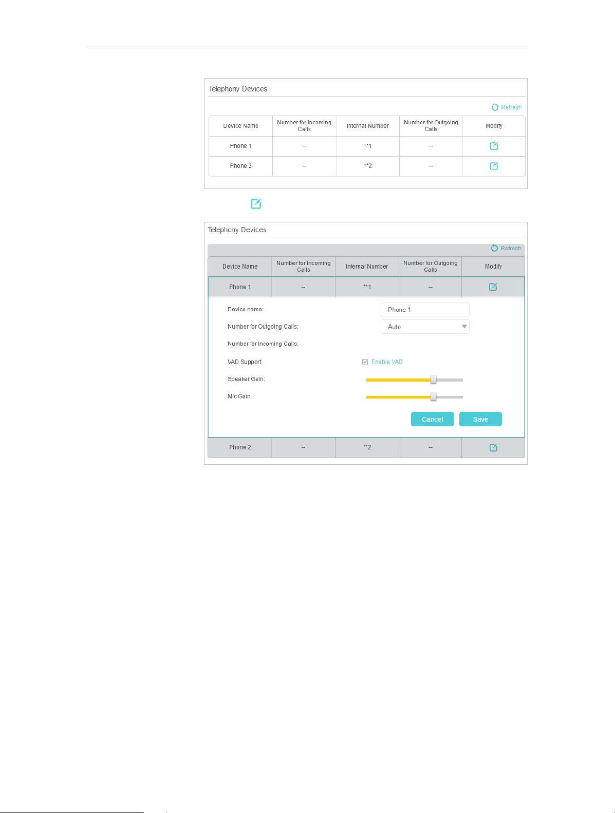
2. Go to Advanced > Telephony > Telephony Devices.
22
Page 27
Chapter 5
VoIP
3. Click to manage your telephony devices.
Done!
4. Device Name: Name the telephone device here.
5. Number for Outgoing Calls: Assign an outgoing number for
this phone.
6. Number for Incoming Calls: Tick the incoming number for
this phone.
7. VAD Support: VAD (Voice Activation Detection) prevents
transmitting the silence packets to consume the bandwidth. It
is also known as Silence Suppression, a software application
that ensures bandwidth when voice activity is activated.
8. Adjust the Speaker Gain slider to control the speaker sound.
9. Adjust the Mic Gain slider to control the speaker sound of
microphone.
10. Click Save to make the settings effective.
Now your telephony devices are bound to different incoming
23
Page 28
Chapter 5
Tips:
Internal number showed on the table are used to make calls between telephony devices connected to the same modem
router. It is preset and cannot be changed.
call numbers and outgoing call numbers.
VoIP
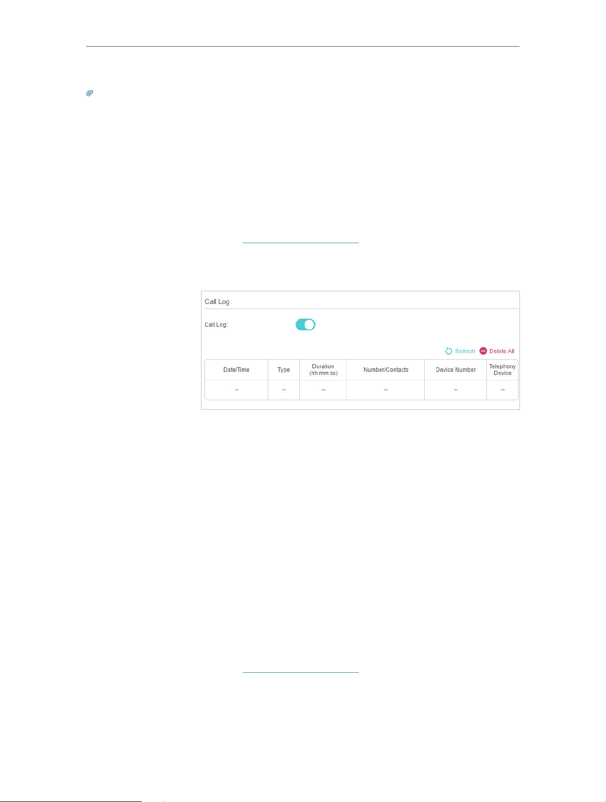
5. 5. Call Log
I want to:
How can I
do that?
Done!
Have a call list recording detailed information of incoming calls
and outgoing calls on your modem router.
1. Visit http://tplinkmodem.net, and log in with the account you
set for the router.
2. Go to Advanced > Telephony > Call Log.
3. Enable Call Log.
From now on, all calls in and out are recorded here. If you’ve
already had a telephone book, name of the contact would be
shown on the call list.
5. 6. Calling via Which Number
I want to:
How can I
do that?
Use different outgoing numbers to call different types of
numbers.
For example, one of my phone number has a relatively low charge
in making long distance calls. I want all long distance calls to be
dialed via this number.
1. Visit http://tplinkmodem.net, and log in with the account you
set for the router.
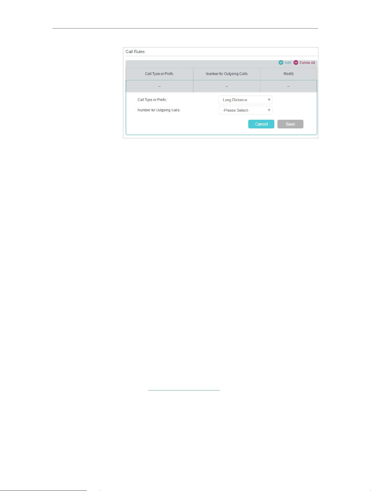
2. Go to Advanced > Telephony > Call Rules. Click Add to set
call rules.
24
Page 29
Chapter 5
3. Choose Long Distance in Call Type or Prefix. Prefixes and call
types can vary according to your own circumstances.
4. In Number for Outgoing Calls, choose the number that has
low charge in making long distance calls.
5. Click Save to make the settings effective.
VoIP
Done!
In addition:
From now on, whenever you are dialing a long distance call, the
call is made via the number you chose in step 5.
Call type can vary according to your circumstances. You can
also set prefix by choosing Calls with Specific Number Prefix in
Call Type or Prefix. When a prefix is set, all numbers with this
prefix is called via the assigned number.
5. 7. Call Blocks
When you do not want calls to be received or dialed, use call block functions. This part
consists of three functions: Do Not Disturb, Block Certain Calls and Prevent from Dialing.
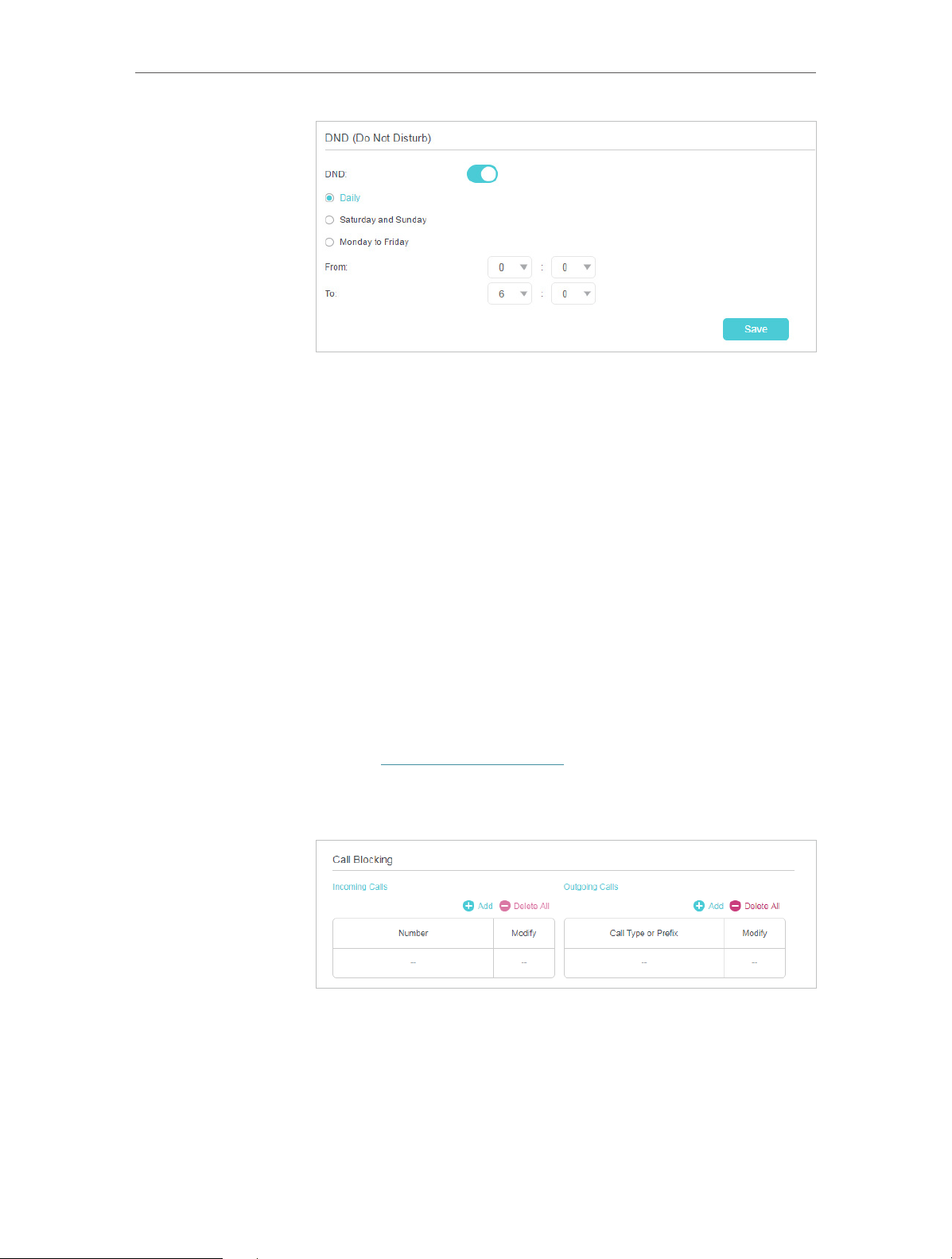
5. 7. 1. Do Not Disturb
I want to:
How can I
do that?
Have no telephone ring at a certain period of time.
1. Visit http://tplinkmodem.net, and log in with the account you
set for the router.
2. Go to Advanced > Telephony > DND & Call Blocking.
25
Page 30
Chapter 5
3. Enable DND.
4. Set the day(s) when DND is enabled.
5. Click Save to make the settings effective.
VoIP
Done!
Now, within this period of time, no telephone will ring, but all
incoming calls would be recorded in call log. Enjoy your peaceful
time and when you are back, check the call log to see what was
missed.
5. 7. 2. Blocking Certain Calls
I want to:
How can I
do that?
Block certain calls, for example, the anonymous calls, or calls
from the annoying salesmen.
1. Visit http://tplinkmodem.net, and log in with the account you
set for the router.
2. Go to Advanced > Telephony > DND & Call Blocking.
Done!
3. Click Add under Incoming Calls.
4. Choose to block a specific number or anonymous calls.
5. Click Save to make the settings effective.
From now on, these calls are all automatically blocked by your
26
Page 31

Chapter 5
modem router.
5. 7. 3. Prevent from Dialing
VoIP
I want to:
How can I
do that?
Prevent my modem router from dialing a certain type of numbers.
For example, it costs a lot to call a mobile phone via my telephone
number, so I don’t want anyone to call a mobile phone using my
number.
1. Visit http://tplinkmodem.net, and log in with the account you
set for the router.
2. Go to Advanced > Telephony > DND & Call Blocking.
3. Click Add under Outgoing Calls.
4. Choose to prevent mobile phone from being dialed. Number
type may vary according to your circumstances.
5. Click Save to make the settings effective.
Done!
In addition:
Now your modem router will prevent all mobile phone from being
dialed.
Number type may vary according to your circumstances. You
can also set prefix by choosing Calls with Specific Number Prefix.
When a prefix is set, all numbers with this prefix is prevented
from being called.
5. 8. Forwarding Calls
I want to:
How can I
do that?
Forward some incoming calls to a designated telephone number.
For example, when no one answers the incoming call, it would be
forwarded to my mobile phone so that I won’t miss it.
1. Visit http://tplinkmodem.net, and log in with the account you
set for the router.
27
Page 32

Chapter 5
2. Go to Advanced > Telephony > Call Forwarding. Click Add to
set how calls should be forwarded.
VoIP
3. Select the incoming calls to be forwarded: Choose to forward
4. Destination Telephone Number: Set the destination where
5. Call Forward Condition: Choose the forwarding type
6. Click Save to make the settings effective.
Done!
Now your modem router will automatically forward the call
according to your rule.
5. 9. Voice Mail
I want to:
Allow the caller who is not answered to leave a voice mail.
For example, I’m on my vocation, and cannot receive any call at
the moment. If people who called can leave a voice mail, I would
know what was going on when I was absent from home. Please
which call or call type.
calls should be forwarded.
(Unconditional or No Answer) of the entry.
28
Page 33

Chapter 5
note that you can use this feature with a storage device plugged
into the USB port.
VoIP
How can I
do that?
1. Visit http://tplinkmodem.net, and log in with the account you
set for the router.
2. Go to Advanced > Telephony > Voice Mail.
Done!
3. Enable Voice Mail.
4. Remote Access Voice Mail: You can access your voice mail
remotely. For the security of your voice mails, this function
is disabled by default. This option is available only when you
have created a new Remote Access PIN in this page.
5. Set the “No answer“ Time. A time period. If the call is not
answered within this time period, the caller can leave a voice
mail.
6. Choose greetings for your Voice Mail. You can record the
greeting by dialing *30 on the keyboard of your telephone.
7. Remote Access PIN: The PIN needed for listening to your
voice mails remotely.
8. Set how long a voice mail can last at Voice Mail Duration.
9. Click Save to make the settings effective.
When a voice mail is recorded, the modem router will display it
in the following table.
29
Page 34

Chapter 5
VoIP
There are three ways to listen to these voice mails.
• Click on the table to listen.
• Press *20 on the telephone keyboard to listen.
• Dial the number of your telephone, press * when you hear the greeting
and follow the voice prompt to enter the Remote Access PIN to listen.
30
Page 35

Chapter 6
USB Settings
This chapter describes how to use the USB ports to share files and media from the USB
storage devices over your home network locally, or remotely through the internet.
The modem router supports USB external flash drives and hard drives.
This chapter contains the following sections:
• Access the USB Storage Device
• Media Sharing
• 3G/4G Settings
Page 36

Chapter 6
USB Settings
6. 1. Access the USB Storage Device
Insert your USB storage device into the modem router’s USB port and then access files
stored there locally or remotely.
Tips:
• If you use USB hubs, make sure no more than 4 devices are connected to the modem router.
• If the USB storage device requires using bundled external power, make sure the external power has been
connected.
• If you use a USB hard drive, make sure its file system is FAT32 or NTFS. Some modem routers also support
the HFS+ and exFAT file systems.
• Before you physically disconnect a USB device from the modem router, safely remove it to avoid data
damage: Go to Advanced > USB Sharing > USB Storage Device and click .
6. 1. 1. Access the USB Device Locally
Insert your USB storage device into the modem router’s USB port and then refer to the
following table to access files stored on your USB storage device:
Windows
computer
¾ Method 1:
Go to Computer > Network, then click the Network Server Name
(ARCHER_model number by default) in the Computer section.
Note:
1. Operations in different systems are similar. Here we take Windows 7 as an example.
2. Network Server Name can be customized on the web management page.
32
Page 37

Chapter 6
Windows
computer
USB Settings
¾ Method 2:
Open the Windows Explorer (or go to Computer) and type the server
address \\tplinkmodem.net or ftp://tplinkmodem.net in the address
bar, then press Enter.
¾ Method 3:
Install an SFTP client (FileZilla) in your computer and configure
the protocol parameters (enter the LAN address of the router and
account username admin and password 000000.
Mac
1 ) Select Go > Connect to Server
2 ) Type the server address smb://tplinkmodem.net
3 ) Click Connect
4 ) When prompted, select the Guest radio box. (If you have set up
a username and a password to deny anonymous access to the
USB disks, you should select the Registered User radio box. To
learn how to set up an account for the access, refer to To Set up
Authentication for Data Security.)
Smart
device
Use a third-party app for network files management.
33
Page 38

Chapter 6
USB Settings
6. 1. 2. Access the USB Device Remotely
You can access your USB disk outside the local area network. For example, you can:
• Share photos and other large files with your friends without logging in to (and paying
for) a photo-sharing site or email system.
• Get a safe backup for the materials for a presentation.
• Remove the files on your camera’s memory card from time to time during the journey.
Note:
If your ISP assigns a private WAN IP address (such as 192.168.x.x or 10.x.x.x), you cannot use this feature because
private addresses are not routed on the Internet.
Follow the steps below to configure remote access settings.
1. Visit http://tplinkmodem.net, then log in with the password you set for the modem
router.
2. Go to Advanced > USB Sharing > USB Storage Device page.
3. Select the check box to enable FTP(via Internet), then click Save.
4. Refer to the following table to access your USB disk remotely.
34
Page 39

Chapter 6
Windows
computer
USB Settings
1 ) Open the Windows Explorer (or go to Computer, only for
Windows users) or open a web browser.
2 ) Type the server address in the address bar:
Type in ftp://<WAN IP address of the modem router>:<port
number> (such as ftp://59.40.2.243:21). If you have specified
the domain name of the modem router, you can also type
in ftp://<domain name>:<port number> (such as ftp://
MyDomainName:21)
The Address Bar of the Windows Explorer (Windows 7)
3 ) Press Enter on the keyboard.
4 ) Access with the username and password you set in To Set up
Authentication for Data Security.
Tips:
You can also access the USB disk via a third-party app for network files management, which
can resume broken file transfers.
Smart
device
Tips:
Click Set Up a Dynamic DNS Service Account to learn how to set up a domain name for you modem router.
Use a third-party app for network files management.
6. 1. 3. Customize the Access Settings
By default, all the network clients can access all folders on your USB disk. You can
customize your sharing settings by setting a sharing account, sharing specific contents
and setting a new sharing address on the modem router’s web management page.
1. Visit http://tplinkmodem.net, then log in with the account you set for the modem
router.
2. Go to Advanced > USB Sharing > USB Storage Device page.
¾ To Customize the Address of the USB Disk
You can customize the server name and use the name to access your USB disk.
1. On the Sharing Settings part, make sure Network Neighborhood is ticked, and enter
a Network/Media Server Name as you like, such as MyShare, then click Save.
35
Page 40

Chapter 6
USB Settings
2. Now you can access the USB disk by visiting \\MyShare (for Windows) or smb://
MyShare (for Mac).
¾ To Only Share Specific Content
1. Focus on the Folder Sharing section. Click the button to disable Share All, then click
Add to add a new sharing folder.
2. Select the Volume Name and Folder Path, then enter a Folder Name as you like.
3. Decide the way you share the folder:
36
Page 41

Chapter 6
USB Settings
• Enable Authentication: Tick to enable authentication for this folder sharing, and
you will be required to log in to the Sharing Account to access the USB disk.
Refer to To Set up Authentication for Data Security to learn more.
• Enable Write Access: If you tick this check box, network clients can modify this
folder.
• Enable Media Sharing: Tick to enable media sharing for this folder, and you can
view photos, play music and watch movies stored on the USB disk directly from
DLNA-supported devices. Click Media Sharing to learn more.
4. Click Save.
Tips:
The modem router can share eight volumes at most. You can click on the page to detach the corresponding volume
you do not need to share.
¾ To Set up Authentication for Data Security
You can set up authentication for your USB device so that network clients will be
required to enter username and password when accessing the USB disk.
1. On the Sharing Accout part, Choose Use Default Account or Use New Account.
The user name is admin and the password is 000000 for Default Account. If your
choose Use New Account, you have to customize the username and a password.
Note:
For Windows users, do not set the sharing username the same as the Windows username. Otherwise, Windows
credential mechanism may cause the following problems:
• If the sharing password is also the same as the Windows password, authentication will not work since the Windows will
automatically use its account information for USB access.
37
Page 42

Chapter 6
• If the sharing password is different from the Windows password, the Windows will be unable to remember your credentials
and you will always be required to enter the sharing password for USB access.
USB Settings
2. Enable Authentication to apply the account you just set.
• If you leave Share All enabled, click the button to enable Authentication for all
folders.
• If Share All is disabled, enable Authentication for specific folders.
Note:
Due to Windows credential mechanism, you might be unable to access the USB disk after changing Authentication
settings. Please log out from the Windows and try to access again. Or you can change the address of the USB disk by
referring to To Customize the Address of the USB Disk.
6. 2. Media Sharing
The feature of Media Sharing allows you to view photos, play music and watch movies
stored on the USB disk directly from DLNA-supported devices, such as your computer,
pad and PS2/3/4.
38
Page 43

Chapter 6
USB Settings
1. When your USB disk is inseted into the modem router, your DLNA-supoorted
devices (such as your computer and pad) connected to the modem router can
detect and play the media files on the USB disks.
2. Refer to the following table for detailed instructions.
• Go to Computer > Network, then click the Media Server Name (Archer_
model number by default) in the Media Devices section.
Note:
Here we take Windows 7 as an example.
Windows
Computer
Smart
device
• Use a third-party DLNA-supported player.
6. 3. 3G/4G Settings
The modem router can be used as a 3G/4G wireless router if you have a 3G/4G USB
modem. There are two ways to use your 3G/4G network:
• As a backup solution for Internet access
• As the only way to access the Internet
39
Page 44

Chapter 6
USB Settings
6. 3. 1. As a Backup Solution for Internet Access
Using 3G/4G network as a backup solution for Internet access, your modem router will
be directly connected to the 3G/4G network when the original network service fails.
When the DSL and WAN port is not connected, 3G/4G network is the only way to access
the Internet.
Follow the steps below to set your 3G/4G network as a backup for Internet access:
1. Plug your USB modem into the USB port of your modem router.
2. Visit http://tplinkmodem.net, then log in with the password you set for the modem
router.
3. Go to Advanced > USB Sharing > 3G/4G Settings, and select the box of Enable
3G/4G as a backup solution for Internet access.
4. Verify that your 3G/4G USB Modem is successfully identified.
Note:
40
Page 45

Chapter 6
The 3G/4G USB modem will not be identified if it is incompatible with the modem router. Find the 3G/4G Compatibility List
on the web page: http://www.tp-link.com/en/comp-list.html. If your USB modem is incompatible, contact our technical
support.
USB Settings
5. Verify that the modem router has correctly recognized your Mobile ISP. When
your Mobile ISP is correct, you have successfully set 3G/4G network as a backup
solution for Internet access. Otherwise, select the box of Set the Dial Number, APN,
Username and Password manually and enter the information provided by your
3G/4G network service provider.
6. Click Advanced to have more configurations if needed.
7. Click Save to make the settings effective.
41
Page 46

Chapter 7
Parental Controls
This function allows you to block inappropriate, explicit and malicious websites, and
control access to specified websites at specified time.
Page 47

Chapter 7
Parental Controls
I want to:
How can I
do that?
Control what types of websites my children or other home
network users can visit and even the time of day they are allowed
to access the Internet.
For example, I want to allow my children’s devices (e.g. a computer
or a tablet) to access only www.tp-link.com and wikipedia.org
from 18:00 (6PM) to 22:00 (10PM) on weekdays and not other
time.
1. Visit http://tplinkmodem.net, and log in with the account you
set for the router.
2. Go to Basic or Advanced > Parental Controls and enable
Parental Controls.
3. Click Add.
43
Page 48

Chapter 7
Parental Controls
4. Click Scan, and add the device to be controlled. Or, enter
the Device Name and MAC Address manually.
5. Click the icon to set the Effctive Time. Drag the cursor
over the appropriate cell(s) and click Save.
6. Enter a Description for the entry.
7. Select the checkbox to enable this entry and click OK.
8. Enable Content Restriction and select the restriction mode.
44
Page 49

Chapter 7
Parental Controls
1 ) In Blacklist mode, the controlled devices cannot access
any websites containing the specified keywords during
the Internet Access Time period.
2 ) In Whitelist mode, the controlled devices can only access
websites containing the specified keywords during the
Effective Time period.
9. Click Add a New Keyword. You can add many keywords for
both Blacklist and Whitelist. Below are some sample entries
to allow access.
Done!
1 ) Enter a web address (e.g. www.tp-link.com) or a web
address keyword (e.g. wikipedia) to only allow or block
access to the websites containing that keyword.
2 ) Specify the domain suffix (eg. .edu or .org) to allow access
only to the websites with that suffix.
10. Enter the keywords or websites you want to add and click
Save.
Now you can control your children’s Internet access according
to your needs.
45
Page 50

Chapter 8
Network Security
This chapter guides you on how to protect your home network from unauthorized users
by implementing these two network security functions. You can use Access Control
for wired and wireless networks, or you can prevent ARP spoofing and ARP attacks by
using IP & MAC Binding.
• Firewall & DoS Protection
• Service Filtering
• Access Control
• IP & MAC Binding
Page 51

Chapter 8
Network Security
8. 1. Firewall & DoS Protection
The SPI (Stateful Packet Inspection) Firewall and DoS (Denial of Service) Protection
protect the router from cyber attacks.
The SPI Firewall can prevent cyber attacks and validate the traffic that is passing
through the router based on the protocol. This function is enabled by default, and it’s
recommended to keep the default settings.
DoS Protection can protect your home network against DoS attacks from flooding your
network with server requests. Follow the steps below to configure DoS Protection.
1. Visit http://tplinkmodem.net, and log in with the account you set for the router.
2. Go to Advanced > Security > Firewall & DoS Protection.
3. Enable DoS Protection.
4. Set the level (Low, Middle or High) of protection for ICMP-FLOOD Attack Filtering,
UDP-FlOOD Attack Filtering and TCP-FLOOD Attack Filtering.
• ICMP-FLOOD Attack Filtering - Enable to prevent the ICMP (Internet Control
Message Protocol) flood attack.
• UDP-FlOOD Attack Filtering - Enable to prevent the UDP (User Datagram
Protocol) flood attack.
• TCP-FLOOD Attack Filtering - Enable to prevent the TCP (Transmission Control
Protocol) flood attack.
5. Click Save.
Tips:
1. The level of protection is based on the number of traffic packets. Specify the level at DoS Protection Level
Settings.
47
Page 52

Chapter 8
2. The protection will be triggered immediately when the number of packets exceeds the preset threshold value,
and the vicious host will be displayed in the Blocked DoS Host List.
Network Security
8. 2. Service Filtering
With Service Filtering, you can prevent certain users from accessing the specified
service, even block internet access completely.
1. Visit http://tplinkmodem.net, and log in with the account you set for the router.
2. Go to Advanced > Security > Service Filtering.
3. Toggle On Service Filtering.
4. Click Add.
48
Page 53

Chapter 8
Network Security
5. Select a Service Type from the drop-down list and the following four fields will be
auto-populated. Select Custom when your desired service type is not listed, and
enter the information manually.
6. Specify the IP address(es) that this filtering rule will apply to.
7. Click Save.
Note: If you want to disable this entry, click the Bulb icon .
8. 3. Access Control
Access Control is used to block or allow specific client devices to access your network
(via wired or wireless) based on a list of blocked devices (Blacklist) or a list of allowed
devices (Whitelist).
I want to:
How can I
do that?
Block or allow specific client devices to access my network (via
wired or wireless).
1. Visit http://tplinkmodem.net, and log in with the account you
set for the router.
2. Go to Advanced > Security > Access Control and enable
Access Control.
49
Page 54

Chapter 8
Network Security
3. Select the access mode to either block (recommended) or
allow the device(s) in the list.
To block specific device(s)
1 ) Select Blacklist and click Save.
2 ) Select the device(s) to be blocked in the Online Devices
table.
3 ) Click Block above the Online Devices table. The selected
devices will be added to Devices in Blacklist automatically.
To allow specific device(s)
1 ) Select Whitelist and click Save.
2 ) Click Add.
50
Page 55

Chapter 8
3 ) Enter the Device Name and MAC Address (You can copy
and paste the information from Devices Online table if
the device is connected to your network).
4 ) Click Save.
Network Security
Done!
Now you can block or allow specific client devices to access your
network (via wired or wireless) using the Blacklist or Whitelist.
8. 4. IP & MAC Binding
IP & MAC Binding, namely, ARP (Address Resolution Protocol) Binding, is used to bind
network device’s IP address to its MAC address. This will prevent ARP spoofing and
other ARP attacks by denying network access to a device with matching IP address in
the Binding list, but unrecognized MAC address.
I want to:
How can I
do that?
Prevent ARP spoofing and ARP attacks.
1. Visit http://tplinkmodem.net, and log in with the account you
set for the router.
2. Go to Advanced > Security > IP & MAC Binding and enable IP
& MAC Binding.
3. Bind your device(s) according to your needs.
To bind the connected device(s)
1 ) Select the device(s) to be bound in the ARP List.
51
Page 56

Chapter 8
Network Security
2 ) Click Bind to add to the Binding List.
To bind the unconnected device
1 ) Click Add.
2 ) Enter the MAC address and IP address that you want to
bind.
Done!
3 ) Select the check box to enable the entry and click Save.
Now you don’t need to worry about ARP spoofing and ARP
attacks.
52
Page 57

Chapter 9
NAT Forwarding
Modem router’s NAT (Network Address Translation) feature makes the devices in the
LAN use the same public IP address to communicate in the Internet, which protects the
local network by hiding IP addresses of the devices. However, it also brings about the
problem that external host cannot initiatively communicate with the specified device in
the local network.
With forwarding feature the modem router can penetrate the isolation of NAT and
allows the external hosts in the Internet to initiatively communicate with the devices in
the local network, thus to realize some special functions.
TP-Link modem router includes four forwarding rules. If two or more rules are set, the
priority of implementation from high to low is Virtual Servers, Port Triggering, UPNP and
DMZ.
This chapter contains the following sections:
• Translate Address and Port by ALG
• Open Ports Dynamically by Port Triggering
• Make Applications Free from Port Restriction by DMZ
• Make Xbox Online Games Run Smoothly by UPnP
Page 58

Chapter 9
NAT Forwarding
9. 1. Translate Address and Port by ALG
ALG (Application Layer Gateway) allows customized NAT (Network Address Translation)
traversal filters to be plugged into the gateway to support address and port translation
for certain application layer “control/data” protocols: FTP, TFTP, H323 etc. Enabling ALG
is recommended.
• PPTP Pass-through: If enabled, it allows Point-to-Point sessions to be tunneled
through an IP network and passed through the router.
• L2TP Pass-through: If enabled, it allows Layer 2 Point-to-Point sessions to be tunneled
through an IP network and passed through the router.
• IPSec Pass-through: If enabled, it allows IPSec (Internet Protocol Security) to
be tunneled through an IP network and passed through the router. IPSec uses
cryptographic security services to ensure private and secure communications over
IP networks.
• FTP ALG: If enabled, it allows FTP (File Transfer Protocol) clients and servers to transfer
data via NAT.
• TFTP ALG: If enabled, it allows TFTP (Trivial File Transfer Protocol) clients and servers
to transfer data via NAT.
• H323 ALG: If enabled, it allows Microsoft NetMeeting clients to communicate via NAT.
• SIP ALG: If enabled, it allows clients communicate with SIP (Session Initiation Protocol)
servers via NAT.
54
Page 59

Chapter 9
NAT Forwarding
9. 2. Share Local Resources in the Internet by Virtual
Server
When you build up a server in the local network and want to share it on the Internet,
Virtual Server can realize the service and provide it to the Internet users. At the same
time virtual server can keep the local network safe as other services are still invisible
from the Internet.
Virtual server can be used for setting up public services in your local network, such as
HTTP, FTP, DNS, POP3/SMTP and Telnet. Different service uses different service port.
Port 80 is used in HTTP service, port 21 in FTP service, port 25 in SMTP service and port
110 in POP3 service. Please verify the service port number before the configuration.
I want to:
How can I
do that?
Share my personal website I’ve built in local network with my
friends through the Internet.
For example, the personal website has been built in my home PC
(192.168.1.100). I hope that my friends in the Internet can visit
my website in some way. The PC is connected to the modem
router with the WAN IP address 218.18.232.154.
Personal Website
Home
Modem Router
LAN
WAN: 218.18.232.154
1. Assign a static IP address to your PC, for example
192.168.1.100.
2. Visit http://tplinkmodem.net, and log in with the account you
set for the router.
3. Go to Advanced > NAT Forwarding > Virtual Servers, click
Add.
55
Page 60

Chapter 9
NAT Forwarding
Done!
4. Click Scan, and choose HTTP. The external port, internal port
and protocol will be automatically filled with contents. Enter
the PC’s IP address 192.168.1.100 in the Internal IP field.
5. Click Save to save the settings.
Tips:
1. It is recommended to keep the default settings of Internal Port and Protocol
if you are not clear about which port and protocol to use.
2. If the service you want to use is not in the Service Type, you can enter the
corresponding parameters manually. You should verify the port number
that the service needs.
3. You can add multiple virtual server rules if you want to provide several
services in a modem router. Please note that the External Port cannot be
overlapped.
Users in the Internet can enter http://WAN IP (in this example:
http://218.18.232.154) to visit your personal website.
Tips:
1. WAN IP should be a public IP address. For the WAN IP is assigned
dynamically by ISP, it is recommended to apply and register a domain name
for the WAN by DDNS, go to Set Up a Dynamic DNS Service Account for
more information. Then you can use http://domain name to visit the website.
2. If you have changed the default External Port, you should use http://WAN
IP: External Port or http://domain name: External Port to visit the website.
9. 3. Open Ports Dynamically by Port Triggering
Port triggering can specify a triggering port and its corresponding external ports. When
a host in the local network initiates a connection to the triggering port, all the external
ports will be opened for subsequent connections. The modem router can record the IP
56
Page 61

Chapter 9
NAT Forwarding
address of the host. When the data from the Internet return to the external ports, the
modem router can forward them to the corresponding host. Port triggering is mainly
applied to online games, VoIPs and video players. Common applications include MSN
Gaming Zone, Dialpad and Quick Time 4 players, etc.
Follow the steps below to configure the port triggering rules:
1. Visit http://tplinkmodem.net, and log in with the account you set for the router.
2. Go to Advanced > NAT Forwarding > Port Triggering and click Add.
3. Click Scan, and select the desired application. The triggering port and protocol, the
external port and protocol will be automatically filled with contents. Here we take
application MSN Gaming Zone as an example.
4. Click Save to save the settings.
Tips:
1. You can add multiple port triggering rules according to your network need.
2. If the application you need is not listed in the Existing Applications list, please enter the parameters manually. You should verify
the external ports the application uses first and enter them into External Port field according to the format the page displays.
9. 4. Make Applications Free from Port Restriction by DMZ
When a PC is set to be a DMZ (Demilitarized Zone) host in the local network, it is totally
exposed to the Internet, which can realize the unlimited bidirectional communication
between internal hosts and external hosts. The DMZ host becomes a virtual server with
all ports opened. When you are not clear about which ports to open in some special
57
Page 62

Chapter 9
applications, like IP camera and database software, you can set the PC to be a DMZ
host.
Note:
DMZ is more applicable in the situation that users are not clear about which ports to open. When it is enabled, the DMZ
host is totally exposed to the Internet, which may bring some potential safety hazard. If DMZ is not in use, please disable
it in time.
NAT Forwarding
I want to:
How can I
do that?
make the home PC join the Internet online game without port
restriction.
For example, Due to some port restriction, when playing the
online games, you can login normally but cannot join a team with
other players. To solve this problem, set your PC as a DMZ with
all ports opened.
1. Assign a static IP address to your PC, for example
192.168.1.100.
2. Visit http://tplinkmodem.net, and log in with the account you
set for the router.
3. Go to Advanced > NAT Forwarding > DMZ and select the
checkbox to enable DMZ.
4. Enter the IP address 192.168.1.100 in the DMZ Host IP
Address filed.
5. Click Save to save the settings.
Done!
The configuration is completed. You’ve set your PC to a DMZ
host and now you can make a team to game with other players.
9. 5. Make Xbox Online Games Run Smoothly by UPnP
UPnP (Universal Plug and Play) protocol allows the applications or host devices
to automatically find the front-end NAT device and send request to it to open the
corresponding ports. With UPnP enabled, the applications or host devices in the
both sides of NAT device can freely communicate with each other realizing the
seamless connection of the network. You may need to enable the UPnP if you want
58
Page 63

Chapter 9
NAT Forwarding
to use applications for multiplayer gaming, peer-to-peer connections, real-time
communication (such as VoIP or telephone conference) or remote assistance, etc.
Tips:
1. UPnP is enabled by default in this modem router.
2. Only the application supporting UPnP protocol can use this feature.
3. UPnP feature needs the support of operating system (e.g. Windows Vista/ Windows 7/ Windows 8, etc. Some of operating
system need to install the UPnP components).
For example, When you connect your Xbox to the modem router which has connected to
the Internet to play online games, UPnP will send request to the modem router to open
the corresponding ports allowing the following data penetrating the NAT to transmit.
Therefore, you can play Xbox online games without a hitch.
LAN
Modem RouterXbox
WAN
If necessary, you can follow the steps to change the status of UPnP.
1. Visit http://tplinkmodem.net, and log in with the account you set for the modem
router;
2. Go to Advanced > NAT Forwarding > UPnP and toggle on or off according to your
needs.
59
Page 64

Chapter 10
VPN Server
The VPN (Virtual Private Networking) Server allows you to access your home network in
a secured way through Internet when you are out of home. The router offers two ways
to setup VPN connection: OpenVPN, PPTP (Point to Point Tunneling Protocol) VPN and
IPSec (Internet Protocol Security) VPN.
OpenVPN is somewhat complex but with greater security and more stable. It is suitable
for restricted environment, such as campus network and company intranet.
PPTP VPN is more easily used and its speed is faster, it’s compatible with most operating
systems and also supports mobile devices. Its security is poor and your packets may
be cracked easily, and PPTP VPN connection may be prevented by some ISP.
IPSec VPN is
This chapter contains the following sections, please choose the appropriate VPN server
connection type according to your needs.
• Use OpenVPN to Access Your Home Network
• Use PPTP VPN to Access Your Home Network
• Use IPSec VPN to Access Your Home Network
Page 65

Chapter 10
VPN Server
10. 1. Use OpenVPN to Access Your Home Network
In the OpenVPN connection, the home network can act as a server, and the remote
device can access the server through the router which acts as an OpenVPN Server
gateway. To use the VPN feature, you should enable OpenVPN Server on your router,
install and run VPN client software on the remote device. Please follow the steps below
to set up an OpenVPN connection.
Step1. Set up OpenVPN Server on Your Router
1. Visit http://tplinkmodem.net, and log in with the account you set for the router.
2. Go to Advanced > VPN > OpenVPN, and select Enable VPN Server.
Note:
• Before you enable VPN Server, we recommend you configure Dynamic DNS Service (recommended) or assign a
static IP address for router’s WAN port and synchronize your System Time with Internet.
• The first time you configure the OpenVPN Server, you may need to Generate a certificate before you enable the
VPN Server.
3. Select the Servive Type (communication protocol) for OpenVPN Server: UDP, TCP.
4. Enter a VPN Service Port to which a VPN device connects, and the port number
should be between 1024 and 65535.
5. In the VPN Subnet/Netmask fields, enter the range of IP addresses that can be leased
to the device by the OpenVPN server.
6. Select your Client Access type. Select Home Network Only if you only want the
remote device to access your home network; select Internet and Home Network if
you also want the remote device to access Internet through the VPN Server.
61
Page 66

Chapter 10
VPN Server
7. Click Save.
8. Click Generate to get a new certificate.
Note:
If you have already generated one, please skip this step, or click Generate to update the certificate.
9. Click Export to save the OpenVPN configuration file which will be used by the remote
device to access your router.
Step 2. Configure OpenVPN Connection on Your Remote Device
1. Visit http://openvpn.net/index.php/download/community-downloads.html to
download the OpenVPN software, and install it on your device where you want to run
the OpenVPN client utility.
Note:
You need to install the OpenVPN client utility on each device that you plan to apply the VPN funxtion to access your
router. Mobile devices should download a third-party app from Google Play or Apple App Store.
2. After the installation, copy the file exported from your router to the OpenVPN client
utility’s “config” folder (for example, C:\Program Files\OpenVPN\config on Windows).
The path depends on where the OpenVPN client utility is installed.
3. Run the OpenVPN client utility and connect it to OpenVPN Server.
10. 2. Use PPTP VPN to Access Your Home Network
PPTP VPN Server is used to create a VPN connection for remote device. To use the VPN
feature, you should enable PPTP VPN Server on your router, and configure the PPTP
connection on the remote device. Please follow the steps below to set up a PPTP VPN
connection.
Step 1. Set up PPTP VPN Server on Your Router
1. Visit http://tplinkmodem.net, and log in with the account you set for the router.
2. Go to Advanced > VPN > PPTP VPN, and select Enable VPN Server.
62
Page 67

Chapter 10
Note:
Before you enable VPN Server, we recommend you configure Dynamic DNS Service (recommended) or assign a static
IP address for router’s WAN port and synchronize your System Time with Internet.
VPN Server
3. In the Client IP Address filed, enter the range of IP addresses (up to 10) that can be
leased to the devices by the PPTP VPN server.
4. Enter the Username and Password to authenticate clients to the PPTP VPN server.
5. Click Save.
Step 2. Configure PPTP VPN Connection on Your Remote Device
The remote device can use the Windows built-in PPTP software or a third-party PPTP
software to connect to PPTP Server. Here we use the Windows built-in PPTP software
as an example.
1. Go to Start > Control Panel > Network and Internet > Network and Sharing Center.
2. Select Set up a new connection or network.
3. Select Connect to a workplace and click Next.
63
Page 68

Chapter 10
VPN Server
4. Select Use my Internet connection (VPN).
5. Enter the Internet IP address of the router (for example: 218.18.1.73) in the Internet
address field. Click Next.
64
Page 69

Chapter 10
VPN Server
6. Enter the Username and Password you have set for the PPTP VPN server on your
router, and click Connect.
7. The PPTP VPN connection is created and ready to use.
65
Page 70

Chapter 10
VPN Server
10. 3. Use IPSec VPN to Access Your Home Network
IPSec VPN is used to creat a VPN connection between local and remote networks. To
use IPSec VPN, you should check that both local and remote routers support IPSec
VPN feature. Then, follow the steps below to set up an IPSec VPN connection.
1. The typical VPN topology is here. Site A refers to local network, and Site B refers to
the remote network that is to be connected. Record Site A and Stie B’s LAN and WAN
IP addresses before you start configuration.
Site A
Modem router 1
PC 1
WAN: 219.134.112.246
LAN: 192.168.1.1
Subnetmask: 255.255.255.0
WAN: 219.134.112.247
LAN: 192.168.2.1
Subnetmask: 255.255.255.0
Modem Router 2
Site B
PC 2
2. Visit http://tplinkmodem.net, and log in with the account you set for the router.
3. Go to Advanced > VPN > IPSec VPN, and click Add.
66
Page 71

Chapter 10
VPN Server
4. In the IPSec Connection Name column, specify a name.
5. In the Remote IPSec Gateway (URL) column, Enter Site B’s WAN IP address.
6. Configure Site A’s LAN.
In the Tunnel access from local IP addresses column, we take Subnet Address as an
example. Input the LAN IP range of Site A in the IP Address for VPN column, and input
Subnet Mask of Site A.
7. Configure Site B’s LAN.
In the Tunnel access from local IP addresses column, we take Subnet Address as an
example. Input the LAN IP range of Site B in the IP Address for VPN column, and input
Subnet Mask of Site B.
8. Select the Key Exchange Method for the policy. We select Auto(IKE) here.
67
Page 72

Chapter 10
VPN Server
9. Enter the Pre-Shared Key for IKE authentication. Then keep Perfect Forward Secrecy
enabled.
Note: Make sure Site A and Site B use the same key.
10. Leave the Advanced Settings as default value. Then click Save to save.
11. Configuration on Site B (remote network). Refer to step 2 configuration on Site A
and make sure that Site A and Site B use the same pre-shared keys and Perfect
Forward Secrecy settings.
12. The Status column will change to UP if the VPN connection has been set up
successfully.
13. Check the VPN connection. You can ping site B’ LAN IP from your computer in site
A to verify that the IPSec VPN connection is set up correctly.
Tips: To check the VPN connection, you can do the following.
1. On the host in Site A, press [Windows Logo] + [R] to open Run dialog. Input “cmd” and hit OK.
2. In the CLI window, type in “ping 192.168.2.x” (“192.168.2.x” can be IP address of any host in Site B). Then press [Enter].
3. If Ping proceeds successfully (gets replies from host in Site B), the IPSec connection is working properly now.
14. Now IPSec VPN is implemented to establish a connection.
Note:
1. The product supports a maximum of ten simultaneous connections.
2. If one of the site has been offline for a while, for example, if Site A has been disconnected, on Site B you need to click Disable
and then click Enable after Site A back on line in order to re-establish the IPSec tunnel.
68
Page 73

Chapter 11
Specify Your Network Settings
This chapter introduces how to change the default settings or adjust the basic
configuration of the modem router using the web management page.
It contains the following sections:
• LAN Settings
• IPv6 LAN Settings
• Wireless Settings
• Set Up a Dynamic DNS Service Account
• Interface Grouping
• Create Static Routes
• Set Up the IPv6 Tunnel
Page 74

Chapter 11
Specify Your Network Settings
11. 1. LAN Settings
11. 1. 1. Change the LAN IP Address
The modem router is preset with a default LAN IP 192.168.1.1, which you can use to log
in to its web management page. The LAN IP address together with the Subnet Mask
also defines the subnet that the connected devices are on. If the IP address conflicts
with another device in your local network or your network requires a specific IP subnet,
you can change it.
Follow the steps below to change your IP address.
1. Visit http://tplinkmodem.net, and log in with the account you set for the router.
2. Go to Advanced > Network > LAN Settings page and select IPv4.
3. Type in a new IP Address appropriate to your needs.
4. Select the Subnet Mask from the drop-down list. The subnet mask together with
the IP address identifies the local IP subnet.
5. Keep IGMP Snooping as enabled by default. IGMP snooping is the process of
listening to IGMP (Internet Group Management Protocol) network traffic. The
function prevents hosts on a local network from receiving traffic for a multicast
group they have not explicitly joined.
6. You can configure the modem router’s Second IP and Subnet Mask for LAN interface
through which you can also access the web management page.
7. Leave the rest of the default settings as they are.
8. Click Save to make the settings effective.
70
Page 75

Chapter 11
Specify Your Network Settings
11. 1. 2. Use the Modem Router as a DHCP Server
You can configure the modem router to act as a DHCP server to assign IP addresses to
its clients. To use the DHCP server function of the modem router, you must configure all
computers on the LAN to obtain an IP Address automatically.
Follow the steps below to configure DHCP server.
1. Visit http://tplinkmodem.net, and log in with the account you set for the router.
2. Go to Advanced > Network > LAN Settings page and select IPv4.
3. Select DHCP to enable the DHCP function and select DHCP Server.
4. Specify the IP Address Pool, the start address and end address must be on the
same subnet with LAN IP. The modem router will assign addresses within this
specified range to its clients. It is from 192.168.1.100 to 192.168.1.199 by default.
5. Enter a value for the Address Lease Time. The Address Lease Time is the amount of
time in which a DHCP client can lease its current dynamic IP address assigned by the
modem router. After the dynamic IP address expires, the user will be automatically
assigned a new dynamic IP address. The default is 1440 minutes.
6. Keep the rest of the settings as default and click Save.
Note:
1. The modem router can be configured to work as a DHCP Relay. A DHCP relay is a computer that forwards DHCP data between
computers that request IP addresses and the DHCP server that assigns the addresses. Each of the device’s interfaces can be
configured as a DHCP relay. If it is enabled, the DHCP requests from local PCs will be forwarded to the DHCP server that runs
on WAN side.
2. You can also appoint IP addresses within a specified range to devices of the same type by using Condition Pool feature. For
example, you can assign IP addresses within the range (192.168.1.50 to192.168.1.80) to Camera devices, thus facilitating the
network management. Enable DHCP feature and configure the parameters according to your actual situation on Advanced >
Network > LAN Settings page.
71
Page 76

Chapter 11
Specify Your Network Settings
11. 1. 3. Reserve LAN IP Addresses
You can view and add a reserved address for a client. When you specify an IP address
for a device on the LAN, that device will always receive the same IP address each time
when it accesses the DHCP server. If there are some devices in the LAN that require
permanent IP addresses, please configure Address Reservation on the router for the
purpose.
Follow the steps below to reserve an IP address for your device.
1. Visit http://tplinkmodem.net, and log in with the account you set for the router.
2. Go to Advanced > Network > LAN Settings page and select IPv4.
3. Scroll down to locate the Address Reservation table and click Add to add an address
reservation entry for your device.
4. Enter the MAC address of the device for which you want to reserve IP address.
5. Specify the IP address which will be reserved by the router.
6. Check to Enable this entry and click Save to make the settings effective.
11. 2. IPv6 LAN Settings
Based on the IPv6 protocol, the modem router provides two ways to assign IPv6 LAN
addresses:
• Configure the RADVD (Router Advertisement Daemon) address type
• Configure the DHCPv6 Server address type
72
Page 77

Chapter 11
Specify Your Network Settings
11. 2. 1. Configure the RADVD Address Type
1. Visit http://tplinkmodem.net, and log in with the account you set for the router.
2. Go to Advanced > Network > LAN Settings.
3. Select IPv6 to configure IPv6 LAN parameters.
1 ) Select the RADVD address type to make the modem router assign IPv6 address
prefixes to hosts.
Note:
Do not select the Enable RDNSS and Enable ULA Prefix check boxes unless required by your ISP. Otherwise
you may not be able to access the IPv6 network. For more information about RDNSS and ULA Prefix, contact
our technical support.
2 ) Keep Site Prefix Type as the default value Delegated. If your ISP has provided a
specific IPv6 site prefix, select Static and enter the prefix.
3 ) Keep WAN Connection as the default value.
4. Click Save to make the settings effective.
11. 2. 2. Configure the DHCPv6 Server Address Type
1. Visit http://tplinkmodem.net, and log in with the account you set for the router.
2. Go to Advanced > Network > LAN Settings.
3. Select IPv6 to configure IPv6 LAN parameters.
73
Page 78

Chapter 11
1 ) Select the DHCPv6 Server address type to make the modem router assign
IPv6 addresses to hosts.
Specify Your Network Settings
2 ) Specify the Start/End IPv6 Address for the IPv6 suffixes. The modem router will
generate IPv6 addresses within the specified range.
3 ) Keep Leased Time as the default value.
4 ) Keep Site Prefix Type as the default value Delegated. If your ISP has provided a
specific IPv6 site prefix, select Static and enter the prefix.
5 ) Keep WAN Connection as the default value.
4. Click Save to make the settings effective.
11. 3. Wireless Settings
11. 3. 1. Specify Basic Wireless Settings
The modem router’s wireless network name (SSID) and password, and security option
are preset in the factory. The preset SSID and password can be found on the product
label. You can customize the wireless settings according to your needs.
Visit http://tplinkmodem.net, and log in with the account you set for the router. Go to
Basic > Wireless page.
74
Page 79

Chapter 11
Specify Your Network Settings
¾ To enable or disable the wireless function:
Enable the 2.4 GHz or 5GHz Wireless Network. If you don’t want to use the wireless
function, just deselect the box. If you disable the wireless function, all the wireless
settings won’t be effective.
¾ To change the wireless network name (SSID) and wireless password:
Enter a new SSID using up to 32 characters. The value is case-sensitive.
Note:
If you use a wireless device to change the wireless settings, you will be disconnected after the new settings are effective.
Please write down the new SSID and password for future use.
¾ To hide SSID:
Select Hide SSID, and your SSID will not broadcast. Your SSID won’t display on your
wireless device when you scan for local wireless network list and you need to manually
join the network.
¾ To change the mode or channel:
Go to Advanced > Wireless >Wireless Settings page and select the wireless network
2.4GHz or 5GHz.
Mode: Select the desired mode.
• 802.11n only: Select only if all of your wireless clients are 802.11n devices.
• 802.11gn mixed: Select if you are using both 802.11g and 802.11n wireless clients.
• 802.11bgn mixed: Select if you are using a mix of 802.11b, 11g, and 11n wireless
clients.
Note: When 802.11n only mode is selected, only 802.11n wireless stations can connect to the modem router. It is
strongly recommended that you select 802.11bgn mixed, and all of 802.11b, 802.11g, and 802.11n wireless stations
can connect to the modem router.
• 802.11ac/n mixed (5GHz): Select if you are using both 802.11ac and 802.11n wireless
clients.
75
Page 80

Chapter 11
• 802.11a/n/ac mixed (5GHz): Select if you are using a mix of 802.11a, 802.11n and
802.11ac wireless clients. It is strongly recommended that you select 11a/n/ac mixed.
Channel: Select the channel you want to use from the drop-down list. This field
determines which operating frequency will be used. It is not necessary to change the
wireless channel unless you notice interference problems with another nearby access
point.
Channel Width: Select the channel width from the drop-down list. The default setting is
Auto, which can adjust the channel width for your clients automatically.
¾ To change the security option:
1. Go to Advanced > Wireless > Wireless Settings page.
2. Select the wireless network 2.4GHz or 5GHz.
3. Select an option from the Security drop-down list. The router provides four options,
None, WPA/WPA2 Personal (Recommended), WPA/WPA2 Enterprise, WEP. WPA2
uses the newest standard and the security level is the highest. We recommend you
don’t change the default settings unless necessary.
Specify Your Network Settings
11. 3. 2. Use WPS for Wireless Connection
You can use WPS (Wi-Fi Protected Setup) feature to add a new wireless device to your
existing network quickly.
Method 1 Use the WPS Button
Use this method if your client device has a WPS button.
1. Press the WPS button the modem router for 1 second.
2. Press the WPS button of the client device directly.
3. The WPS LED flashes for about 2 minutes during the WPS process.
4. When the WPS LED is on, the client device has successfully connected to the
modem router.
Method 2 Use the WPS Button on the Web Management Page
Use this method if your client device has a WPS button.
1. Visit http://tplinkmodem.net, and log in with the account you set for the router.
2. Go to Advanced > Wireless > WPS page.
76
Page 81

Chapter 11
Specify Your Network Settings
3. Click Start WPS on the page.
4. Press the WPS button of the client device directly.
5. The WPS LED of the router flashes for about 2 minutes during the WPS process.
6. When the WPS LED is on, the client device has successfully connected to the
modem router.
Method 3 Enter the modem router’s PIN on your client device
Use this method if your client device asks for the modem router’s PIN.
1. Visit http://tplinkmodem.net, and log in with the account you set for the router.
2. Go to Advanced > Wireless > WPS page. Click Method Two--PIN.
3. Take a note of the Current PIN of the modem router. You can also click the Generate
button to get a new PIN.
4. On the client device, enter the modem router’s PIN. (The default PIN is also printed
on the label of the modem router.)
5. The WPS LED flashes for about two minutes during the WPS process.
6. When the WPS LED is on, the client device has successfully connected to the
modem router.
Note:
1. The WPS LED on the modem router will light on for five minutes if the device has been successfully added to the network.
2. The WPS function cannot be configured if the wireless function of the modem router is disabled. Please make sure the wireless
function is enabled before configuring the WPS.
Method 4 Enter the client device’s PIN on the modem router
1. Visit http://tplinkmodem.net, and log in with the account you set for the router.
2. Go to Advanced > Wireless > WPS page. Click Method Two--PIN.
77
Page 82

Chapter 11
Specify Your Network Settings
3. Select Client’s PIN.
4. Enter the client device’s PIN in the field. Then click the Connect button.
5. Connect successfully will appear on the above screen, which means the client
device has successfully connected to the modem router.
11. 3. 3. Schedule Your Wireless Function
You can automatically turn off your wireless network (both 2.4GHz and 5GHz) when you
do not need the wireless connection.
1. Visit http://tplinkmodem.net, and log in with the account you set for the router.
2. Go to Advanced > Wireless > Wireless Schedule page.
3. Toggle on the button to enable the Wireless Schedule feature.
4. Click Add to set the Wireless Off Time, and click Save to save the settings.
5. Repeat steps 3 and 4 to set another entry.
Note:
78
Page 83

Chapter 11
1. Make sure that the time of the router is correct before using this function. For details, refer to Set System Time.
2. If you just set time for one wireless band, the other wireless band is still always on, so set time for both of the two bands to
schedule your whole wireless network.
3. The wireless LED (2.4GHz , 5GHz) will turn off if the corresponding wireless network is disabled.
4. The wireless network will be automatically turned on after the time period you set.
Specify Your Network Settings
11. 3. 4. View Wireless Information
¾ To view the detailed wireless network settings:
1. Visit http://tplinkmodem.net, and log in with the account you set for the router.
2. Go to Advanced > Status page. You can see the Wireless box.
3. Select 2.4GHz or 5GHz to view the wireless details.
Tips: You can also see the wireless details by clicking the router icon on Basic> Network Map.
¾ To view the detailed information of the connected wireless clients:
1. Visit http://tplinkmodem.net, and log in with the account you set for the router.
2. Go to Advanced > Wireless > Statistics page.
3. You can view the detailed information of the wireless clients, including its connected
wireless band and security option as well as the packets transmitted.
Tips: You can also see the wireless details by clicking the wireless clients icon on Basic> Network Map.
11. 3. 5. Advanced Wireless Settings
Advanced wireless settings are for those who have a network concept. If you are not
familiar with the settings on this page, it’s strongly recommended that you keep the
provided default values; otherwise it may result in lower wireless network performance.
1. Visit http://tplinkmodem.net, and log in with the account you set for the router.
2. Go to Advanced > Wireless > Advanced Settings page.
79
Page 84

Chapter 11
Specify Your Network Settings
• Beacon Interval: Enter a value between 25 and 1000 in milliseconds to determine the
duration between which beacon packets are broadcasted by the router to synchronize
the wireless network. The default is 100 milliseconds.
• RTS Threshold: Enter a value between 1 and 2346 to determine the packet size of
data transmission through the router. By default, the RTS (Request to Send) Threshold
size is 2346. If the packet size is greater than the preset threshold, the router sends
Request to Send frames to a particular receiving station and negotiates the sending
of a data frame, or else the packet will be sent immediately.
• DTIM Interval: Enter a value between 1 and 255 to determine the interval of the
Delivery Traffic Indication Message (DTIM). 1 indicates the DTIM Interval is the same
as Beacon Interval.
• Group Key Update Period: Enter the number of seconds to control the time interval
for the encryption key automatic renewal. The default is 0, indicating no key renewal.
• WMM: This feature guarantees the packets with high-priority messages being
transmitted preferentially. WMM is enabled compulsively under 802.11n or 802.11ac
mode. It is strongly recommended to enable WMM.
• Short GI: This feature is enabled by default and recommended to increase the data
capacity by reducing the Guard Interval (GI) time.
• AP Isolation: Select this check box to enable the AP Isolation feature that allows you
to confine and restrict all wireless devices on your network from interacting with each
other, but still able to access the Internet. AP isolation is disabled by default.
• WDS Bridging(for 2.4GHz only): Select this check box to enable the WDS (Wireless
Distribution System) Bridging feature to allow the router to bridge with another access
80
Page 85

Chapter 11
point (AP) in a wireless local area network (WLAN). Refer to Appendix: Troubleshooting
for detailed instructions.
Specify Your Network Settings
11. 4. Set Up a Dynamic DNS Service Account
Most ISPs (Internet service providers) assign a dynamic IP address to the router and
you can use this IP address to access your router remotely. However, the IP address
can change any time and you don’t know when it changes. In this case, you might need
the DDNS (Dynamic Domain Name Server) feature on the router to allow you and your
friends to access your router and local servers (FTP, HTTP, etc.) using domain name, in
no need of checking and remembering the IP address.
Note: DDNS does not work if the ISP assigns a private WAN IP address (such as 192.168.1.x) to the modem router.
To set up DDNS, please follow the instructions below:
1. Visit http://tplinkmodem.net, and log in with the account you set for the router.
2. Go to Advanced > Network> Dynamic DNS.
3. Select the DDNS service provider (Dyndns, NO-IP and many other DNS services).
4. Log in with your DDNS account, select a service provider and click Go to register.
Enter the username, password and domain name of the account (such as lisa.ddns.
net).
5. Click Log in and Save.
Tips: If you want to use a new DDNS account, please Logout first, then login with the new account.
11. 5. Interface Grouping
I want to:
Divide my devices connected to the modem router into different
groups and disallow devices’ cross-group communication.
For example, in my house, devices connected to LAN1 and LAN3
are for work, while others for entertainment. I want to isolate
81
Page 86

Chapter 11
Specify Your Network Settings
working devices from others while keep all devices’ access to
the internet.
How can I
do that?
1. Visit http://tplinkmodem.net, and log in with the account you
set for the router.
2. Go to Advanced > Network > Interface Grouping to open the
configuration page where some interfaces can be grouped
together.
3. Click to Add a new group.
4. Name the group.
5. Check the boxes of LAN1 and LAN3 in Available LAN. Here
Wi-Fi 2.4G network and Wi-Fi 5G network are viewed as a
LAN interface respectively.
82
Page 87

Chapter 11
Specify Your Network Settings
6. Click Enable Group Isolation to isolate working devices and
disallow other devices from communicating with them.
7. Click Save to save the settings.
Done!
Now your working devices connected to LAN1 and LAN3 are in
an isolated group!
Note: VLAN function is enabled by default. You cannot disable it when IPTV
is enabled.
11. 6. Create Static Routes
A static route is a pre-determined path that network information must travel to reach
a specific host or network. Data from one point to another will always follow the same
path regardless of other considerations. Normal Internet usage does not require this
setting to be configured.
I want to:
Visit multiple networks and multiple servers at the same time.
For example, in a small office, my PC can surf the Internet, but I
also want to visit my company’s server. Now I have a switch and
another router. I connect the devices as shown in the following
figure so that the physical connection between my PC and my
company’s server is achieved. To surf the Internet and visit my
company’s network at the same time, I need to configure the
static routing.
How can I
do that?
Modem router
LAN: 192.168.1.1
Switch
192.168.1.100
Router 2
WAN: 172.30.30.100
LAN: 192.168.1.2
My PC
Company’s server
172.30.30.1
1. Make sure the routers use different LAN IP addresses on the
same subnet. Disable Router 2’s DHCP function.
2. Visit http://tplinkmodem.net, and log in with the account you
set for the router.
3. Go to Advanced > Network > Static Routing. Select your
current WAN Interface and click Save.
83
Page 88

Chapter 11
Specify Your Network Settings
4. Click Add to add a new static routing entry. Finish the settings
according to the following explanations:
• Network Destination: The destination IP address that you
want to assign to a static route. This IP address cannot be on
the same subnet with the WAN IP or LAN IP of the router. In
the example, the IP address of the company network is the
destination IP address, so here enters 172.30.30.1.
• Subnet Mask: Determines the destination network with the
destination IP address. If the destination is a single IP address,
enter 255.255.255.255; otherwise, enter the subnet mask of
the corresponding network IP. In the example, the destination
network is a single IP, so here enters 255.255.255.255.
• Gateway: The IP address of the gateway device to which the
data packets will be sent. This IP address must be on the
same subnet with the router’s IP which sends out the data. In
the example, the data packets will be sent to the LAN port of
84
Page 89

Chapter 11
Router 2 and then to the Server, so the default gateway should
be 192.168.1.2.
• Interface: Determined by the port (WAN/LAN) that sends
out the data packets. In the example, the data is sent to the
gateway through the LAN port, so LAN should be selected.
5. Select the check box to enable this entry.
6. Click Save to save the settings.
Specify Your Network Settings
Done!
Open a web browser on your PC. Enter the company server’s IP
address to visit the company network.
11. 7. Set Up the IPv6 Tunnel
The IPv6 Tunnel feature helps you obtain IPv6 resources based on an IPv4 WAN
connection or vice versa.
IPv6 Tunnel is a transition mechanism that enables IPv6-only hosts to reach IPv4
services or vice versa and allows isolated IPv6 hosts and networks to reach each other
over IPv4-only infrastructure before IPv6 completely supplants IPv4. It is a temporary
solution for networks that do not support native dual-stack, where both IPv6 and IPv4
run independently.
The modem router provides three tunneling mechanisms: 6to4, 6rd and DS-Lite. The
way to set up 6rd and DS-Lite tunnel are similar.
11. 7. 1. Use the Public IPv6 Tunnel Service-6to4
The 6to4 tunnel is a kind of public service. If there is any 6to4 server in your network,
you can use this mechanism to access IPv6 service. If your ISP provides you with an
IPv4-only connection but you want to visit IPv6 websites, you can try to set up a 6to4
tunnel.
I want to:
How can I
do that?
Set up the IPv6 tunnel though my ISP doesn’t provide me with
the tunnel service.
1. Visit http://tplinkmodem.net, and log in with the account you
set for the router.
2. Go to Advanced > Network > IPv6 Tunnel.
3. Tick the check box, select 6to4 as the tunneling mechanism
and select a WAN connection from the drop-down list, then
click Save.
85
Page 90

Chapter 11
Note:
If there is no available WAN connection to choose, make sure you have
connected to the Internet and the connection type is not Bridge.
Specify Your Network Settings
Done!
Note:
Still not being able to access IPv6 resources means that not any 6to4 public server was found in your network. You can
contact your ISP to sign up for IPv6 connection service.
Now you can visit the IPv6 websites with the 6to4 tunnel.
11. 7. 2. Specify the 6rd Tunnel with Parameters Provided by Your ISP
I want to:
How can I
How can I
do that?
do that?
Specify the 6rd tunnel with the parameters provided by my 6rd
tunnel service provider.
1. Visit http://tplinkmodem.net, and log in with the account you
set for the router.
2. Go to Advanced > Network > IPv6 Tunnel.
3. Tick the check box, select 6rd as the tunneling mechanism
and select a WAN connection from the drop-down list.
4. According to the parameters provided by your ISP, choose
Auto or Manual. More parameters are needed if you choose
Manual.
5. Click Save.
86
Page 91

Chapter 11
Note:
If there is no available WAN connection to choose, make sure you have
connected to the Internet and the connection type is not Bridge.
Specify Your Network Settings
Done!
Tips:
The way to set up DS-Lite tunnel is similar to that of 6rd tunnel. If you are provided with an IPv6-only WAN connection
and have signed up for DS-Lite tunnel service, specify the DS-Lite tunnel by referring to the steps above.
Now you can visit the IPv6 websites with the 6rd tunnel.
87
Page 92

Chapter 12
Administrate Your Network
This chapter introduces how to change the system settings and administrate your
modem router’s network.
This chapter contains the following sections:
• Set System Time
• Back up and Restore Configuration Settings
• Change the Administrator Account
• Local Management
• Remote Management
• System Log
• CWMP Settings
• SNMP Settings
Page 93

Chapter 12
Administrate Your Network
12. 1. Set System Time
System time is the time displayed while the modem router is running. The system time
you configure here will be used for other time-based functions like Parental Controls
and Wireless Schedule. You can manually set how to get the system time.
Follow the steps below to set your system time.
1. Visit http://tplinkmodem.net, and log in with the password you set for the modem
router.
2. Go to Advanced > System Tools > Time Settings page.
3. Configure the system time using the following methods:
Manually: Select your time zone and enter your local time.
Get from PC: Click this button if you want to use the current managing PC’s time.
Get from the Internet: Click this button if you want to get time from the Internet.
Make sure your modem router can access the Internet before you select this way
to get system time.
4. Click Save.
5. After setting the system time, you can set Daylight Saving Time according to your
needs. Tick the checkbox to enable Daylight Saving Time, set the start and end
time and then click Save to make the settings effective.
89
Page 94

Chapter 12
Administrate Your Network
12. 2. Update the Firmware
TP-Link is dedicated to improving and richening the product features, giving you a
better network experience.
We will inform you through the web management page if there’s any update firmware
available for your router. Also, the latest firmware will be released at TP-Link official
website, you can download it from the Support page of our website www.tp-link.com
for free.
Note:
1. Make sure that you have a stable connection between the router and your computer. It is NOT recommended to upgrade the
firmware wirelessly.
2. Make sure you remove any USB storage device connected to the router before the firmware upgrade to prevent data loss.
3. Back up your router configuration before upgrading the firmware.
4. Do NOT turn off the router during the firmware upgrade.
12. 2. 1. Local Upgrade
1. Download the latest firmware file for the router from our website www.tp-link.com.
2. Visit http://tplinkmodem.net, and log in with the account you set for the router.
3. Go to Advanced > System Tools > Firmware Upgrade.
4. Focus on the Device Information section. Make sure the downloaded firmware file
matches with the Hardware Version.
5. Focus on the Local Upgrade section. Click Browse to locate the downloaded new
firmware file, and click Upgrade.
6. Wait a few moments for the upgrading and rebooting.
90
Page 95

Chapter 12
Administrate Your Network
12. 3. Back up and Restore Configuration Settings
The configuration settings are stored as a configuration file in the router. You can back
up the configuration file to your computer for future use and restore the modem router
to a previous settings from the backup file when needed. Moreover, if needed you can
erase the current settings and reset the modem router to the default factory settings.
¾ To back up configuration settings
1. Visit http://tplinkmodem.net, and log in with the account you set for the router.
2. Click Advanced > System Tools > Backup & Restore page.
3. Click Backup to save a copy of the current settings to your local computer. A conf.
bin file will be stored to your computer.
¾ To restore configuration settings
1. Visit http://tplinkmodem.net, and log in with the account you set for the router.
2. Click Advanced > System Tools > Backup & Restore page.
3. Click Browse to locate the previous backup configuration file, and click Restore.
4. Wait for the restoring and then the modem router will automatically reboot.
¾ To reset the modem router to factory default settings
1. Visit http://tplinkmodem.net, and log in with the account you set for the router.
2. Click Advanced > System Tools > Backup & Restore page.
3. Click Restore to restore all configuration settings to default values, except your
login and TP-Link ID information. Click Factory Restore to reset the modem router.
4. Wait for the resetting and then the modem router will automatically reboot.
Note:
1. During the resetting process, do not turn off the modem router.
2. We strongly recommend you back up the current configuration settings before resetting the modem router.
12. 4. Change the Administrator Account
Admin account is used to log in to the modem router’s web management page. You are
required to set the admin account at first login. You can also change it on the web page.
91
Page 96

Chapter 12
1. Visit http://tplinkmodem.net, and log in with the account you set for the router.
2. Go to Advanced > System Tools> Administration page. Locate the Account
Management section.
3. Enter the old password. Enter the new password and enter again to confirm.
4. Click Save to make the settings effective.
Administrate Your Network
12. 5. Local Management
You can control the local devices’ authority to manage the modem router via Local
Management feature. By default all local connected devices are allowed to manage the
modem router. You can also allow only one device to manage the modem router and
enable local management over a more secure way, HTTPS.
¾ To allow only the specific device to manage the router via the local management
over HTTPS
1. Visit http://tplinkmodem.net, and log in with the account you set for the router.
2. Go to Advanced > System Tools > Administration page. Locate the Local
Management section.
3. Keep the Port as the default setting. Enable Management over HTTPS and keep the
Port for HTTPS as the default setting. Enter the IP address or MAC address of the
local device to manage the modem router.
92
Page 97

Chapter 12
Administrate Your Network
4. Click Save.
Now, you can manage the modem router over both HTTP (http://tplinkmodem.net) and
HTTPS (https://tplinkmodem.net).
Note:
If you want that all local devices can manage the modem router, just leave the IP/MAC Address field blank.
12. 6. Remote Management
By default, the remote devices are not allowed to manage the modem router from the
internet. You can enable remote management over HTTP and/or HTTPS if needed.
HTTPS is a more secure way to access the router.
Note:
If your ISP assigns a private WAN IP address (such as 192.168.x.x or 10.x.x.x), you cannot use the remote management
feature because private addresses are not routed on the internet.
Follow the steps below to allow remote devices to mange the modem router over
HTTPS.
1. Visit http://tplinkmodem.net, and log in with the account you set for the router.
2. Go to Advanced > System Tools > Administration page. Locate the Remote
Management section.
3. Tick the checkbox to enable Remote Management. Enable Remote Management
via HTTPS to allow for HTTPS connection. Keep the Port as the default setting.
4. Set the client device allowed for remote management. Select All to allow all remote
devices to manage the modem router. If you just want to allow a specific device to
manage the modem router, select Only the Following IP/MAC Address and enter the
IP/MAC address of the remote device.
5. Click Save.
93
Page 98

Chapter 12
Administrate Your Network
All devices or the specific device on the internet can log in to your router using the
address displayed on the Manage This Router via the Address field to manage the
modem router.
Tips:
1. If you were warned about the certificate when visiting the web management page remotely, click Trust (or a similar option) to
continue. To avoid this warning, you can download and install the certificate on the modem router’s web management page at
Advanced > System Tools > Administration.
2. The router’s WAN IP is usually a dynamic IP. Please refer to Set Up a Dynamic DNS Service Account if you want to log in to
the router through a domain name.
12. 7. System Log
System Log can help you know what happened to your modem router, facilitating
you to locate the malfunctions. For example when your modem router does not work
properly, you will need to save the system log and send it to the technical support for
troubleshooting.
1. Visit http://tplinkmodem.net, and log in with the account you set for the router.
2. Click Advanced > System Tools > System Log page.
¾ To view the system logs:
You can view specific system logs by selecting the log Type and Level.
Click Refresh to refresh the log list.
¾ To save the system logs:
You can choose to save the system logs to your local computer or a remote server.
94
Page 99

Chapter 12
Click Save Log to save the logs in a txt file to your computer.
Click Log Settings to set the storage path of logs.
• Save Locally: Select this option to cache the system log to the router’s local memory,
select the minimum level of system log to be saved from the drop-down list. The logs
will be shown in the table in descending order on the System Log page.
Administrate Your Network
• Save Remotely: Select this option to send the system log to a remote server, select
the minimum level of system log to be saved from the drop-down list and enter the
information of the remote server. If the remote server has a log viewer client or a sniffer
tool implemented, you can view and analyze the system log remotely in real-time.
12. 8. CWMP Settings
The modem router offers CWMP feature. The function supports TR-069 protocol which
collects information, diagnoses the devices and configures the devices automatically
via ACS (Auto-Configuration Server).
1. Visit http://tplinkmodem.net, and log in with the account you set for the router.
2. Go to Advanced > System Tools > CWMP Settings page.
95
Page 100

Chapter 12
Administrate Your Network
• CWMP: Toggle On to enable the CWMP (CPE WAN Management Protocol) feature.
• Inform: Enable this feature to send an Inform message to the ACS (Auto Configuration
Server) periodically.
• Inform Interval: Enter the time interval in seconds when the Inform message will be
sent to the ACS.
• ACS URL: Enter the web address of the ACS which is provided by your ISP.
• ACS Username/Password: Enter the username/password to log in to the ACS server.
• Interface used by TR-069 client: Select which interface to be used by the TR-069
client.
• Display SOAP messages on serial console: Toggle to enable or disable this feature.
• Connection Request Authentication: Select this checkbox to enable authentication
for the connection request.
• Username/Password: Enter the username/password for the ACS server to log in to
the router.
• Path: Enter the path for the ACS server to log in to the router.
96
 Loading...