

Toyota GRJ120L Installation Manual

GRJ120L
AIR CONDITIONING
ENGLISH-DEUTSCH-FRANÇAIS
EUROPE
INSTALLATION MANUAL
INSIDE PASSENGER COMPARTMENT & INSIDE ENGINE COMPARTMENT

INTRODUCTION
IMPORTANT NOTICE
This manual has been designed for technicians who are qualified and educated in the proper procedures of vehicle
safety, handling and maintenance; experienced in installation of car air conditioning or who are able to carry out
installation procedures when given instructions by an experienced technician in a supervisory capacity; and are
certified to handling refrigerant.
1. Take special care to ensure that clearance between air conditioning components and other components such as
brake parts, fuel system and electric wires as specified in this manual.
2. If a problem is found with the air conditioning system due to installation, refer back to the manual to correct the
problem(s).
3. Vehicle and air conditioning kit components as well as installation procedures are subject to change without
prior notice. Refer to the latest installation manual and service information. Any changes affecting the above
items will be given in the form of a “Installation instructions for air conditioning (Supplement)” (issued by
DENSO) or a service bulletin (issued by the manufacturer).
DEFINITION OF TERMS
ENGLISH
WARNING
CAUTION
NOTE
FRONT,REAR
:Describes precautions that should be observed in order to prevent injury or death to the user
during installation.
:Describes precautions that should be observed in order to prevent damage to the vehicle or its
components, which may occur during installation if insufficient care is taken.
:Provides additional information that facilitates installation work.
:Shows the direction when viewed from the driver's seat.
LEFT,RIGHT
FOREWORD
This manual has been published to explain how to install the air conditioning for TOYOTA LAND CRUISER.
When installing the air conditioning, installation should be performed as described in this manual.
[APPLICATION VEHICLE]
VEHICLE NAME MODEL CODE PRODUCTION PERIOD ENGINE TYPE STEERING POSITION
LANDCRUISER
CAUTION
Carefully read the separate manual "GENERAL INFORMATION/AFTER INSTALLATION" before and after
installation.
GRJ120L
2005.7- 1GR-FE LHD
[DOCUMENT CODE AND DOCUMENT PART NUMBER]
MANUAL NAME DOCUMENT CODE DOCUMENT PART NUMBER
GENERAL INFORMATION /
AFTER INSTALLATION
© 2005 DENSO CORPORATION
All Rights Reserved. This book may not be reproduced
or copied, in whole or in part, without the written
permission of the publisher.
00502437EA
AOUMC-01* 988963-476*
EINLEITUNG
WICHTIGER HINWEIS
Diese Anleitung wurde für qualifizierte Techniker geschrieben, die mit der richtigen Wartung, und den erforderlichen
Sicherheitsregeln bei der Arbeit an Fahrzeugen vertraut sind, die Erfahrung beim Einbau von Klimaanlagen in
Fahrzeugen haben oder diese Arbeit unter sachkundiger Anleitung ausführen können, und die zum Umgang mit
Kältemittel befugt sind.
1. Stellen Sie sicher, daß ausreichend Abstand zwischen den Bauteilen der Klimaanlage und anderen Bauteilen
wie Teilen der Bremsanlage, Kraftstoffanlage und Autoelektrik vorhanden ist, wie in dieser Anleitung
beschrieben.
2. Wenn ein Problem mit der Klimaanlage auftritt, das sich auf die Installation zurückführen läßt, schlagen Sie in
der Einbauanleitung nach, um das Problem zu beheben.
3. Änderungen bei Fahrzeugeinbauteilen und Bauteilen der Klimaanlage bleiben vorbehalten. Richten Sie sich
nach der aktuellsten Anleitung und Serviceinformation. Änderungen, die die obigen Teile betreffen, können in
Form von “Einbauinstallationen für Klimaanlagen (Ergänzung)” (herausgegeben von DENSO) oder als
Wartungsblatt (herausgegeben vom Hersteller) mitgeteilt werden.
DEFINITION DER VERWENDETEN KENNZEICHNUNGEN
DEUTSCH
WARNUNG
ACHTUNG
HINWEIS
VORNE,HINTEN
:Beschreibt die Vorsichtsmaßregeln, die befolgt werden müssen, um Unfälle mit Verletzungen,
möglicherweise mit Todesfolge, beim Einbau zu vermeiden.
:Beschreibt die Vorsichtsmaßregeln, die befolgt werden müssen, Schäden am Fahrzeug oder an
Bauteilen beim Einbau zu vermeiden.
:Gibt zusätzliche Informationen zur Erleichterung der Einbauarbeit.
:Gibt die Richtung an, gesehen vom Fahrersitz aus.
LINKS,RECHTS
VORWORT
TDiese Anleitung wurde erstellt, um den Einbau des Klimageräts in den TOYOTA LAND CRUISER zu erläutern.
Beim Einbau des Klimageräts müssen die Angaben dieser Anleitung befolgt werden.
[BETREFFENDE FAHRZEUGE]
FAHRZEUGBEZEICHNUNG MODELLCODE PRODUKTIONSZEITRAUM MOTORTYP LENKRADPOSITION
LANDCRUISER GRJ120L 2005.7- 1GR-FE LL
ACHTUNG
Vor und nach der Installation die getrennte Anleitung "GENERAL INFORMATION/AFTER INSTALLATION"
sorgf,ltig durchlesen.
[DOKUMENTENCODE UND DOKUMENTEN-TEILENUMMER]
ANLEITUNGBEZEICHNUNG DOKUMENTENCODE DOKUMENTEN-TEILENUMMER
GENERAL INFORMATION /
AFTER INSTALLATION
© 2005 DENSO CORPORATION
Alle Rechte vorbehalten. Dieses Buch darf, weder ganz noch
in Teilen, ohne schriftliche Genehmigung des Herausgebers
in keiner Form reproduziert oder vervielfältigt werden.
AOUMC-01* 988963-476*
00502437EA
INTRODUCTION
NOTICE IMPORTANTE
Ce manuel a été conçu pour les techniciens qualifiés et formés dans le domaine de la sécurité automobile,
l’installation et la maintenance, ayant une expérience de l’installation des climatiseurs auto, ou capables de les
installer sous la conduite d’un technicien expérimenté, et autorisés à manipuler le réfrigérant.
1. Prenez les précautions nécessaires pour que le jeu entre les pièces du climatiseur et les autres pièces, telles
les pièces du système de freinage, le système d’alimentation en carburant et les fils électriques, corresponde
aux spécifications indiquées dans ce manuel.
2. En cas de problème dû à l’installation du climatiseur, veuillez consulter le manuel pour résoudre le(s)
problème(s).
3. Les pièces du véhicule, les pièces du kit climatiseur et les instructions d’installation peuvent être changées sans
avis préalable. Veuillez vous référer aux toutes dernières informations d’entretien et au dernier manuel
d’installation. Tous ces changements seront indiqués dans la brochure “Instructions d’installation de climatiseur
(Supplément)” (publié par DENSO) ou dans un bulletin de service (publié par le fabricant).
DEFINITION DES TERMES
AVERTISSEMENT
ATTENTION
REMARQUE
AVANT,ARRIERE
:Décrit les précautions dont il faut tenir compte afin d'éviter toute blessure ou décès de
l'utilisateur pendant l'installation.
:Dé crit les précautions dont il faut tenir compte pour éviter tout endommagement du
véhicule ou des pièces.
:Fournit des informations complémentaires qui facilitent le travail d'installation.
:Indique le sens à partir du siège du conducteur.
GAUCHE,DROITE
AVANT-PROPOS
Le but de ce manuel est de donner les explications nécessaires pour l’installation du climatiseur dans les TOYOTA LAND
CRUISER.
Lors de l’installation du climatiseur, il est indispensable de suivre exactement les instructions de ce manuel.
[VEHICULE CONCERNE]
NOM DU VEHICULE CODE DE MODELE PERIODE DE PRODUCTION TYPE DE MOTEUR CONDUITE
LANDCRUISER
ATTENTION
Lire attentivement le manuel séparés "GENERAL INFOEMATION/AFTER INSTALLATION", avant et après
l'installation.
GRJ120L
2005.7- 1GR-FE GAUCHE
FRANÇAIS
[DOCUMENT CODE AND DOCUMENT PART NUMBER]
NOM DU MANUEL CODE DU DOCUMENT NUMERO DE PIECE DU DOCUMENT
GENERAL INFORMATION /
AFTER INSTALLATION
© 2005 DENSO CORPORATION
Tous droits réservés. Toute reproduction ou copie,
partielle ou complète, sans autorisation de l’éditeur
est interdite.
AOUMC-01* 988963-476*
00502437EA
1. INSTALLATION
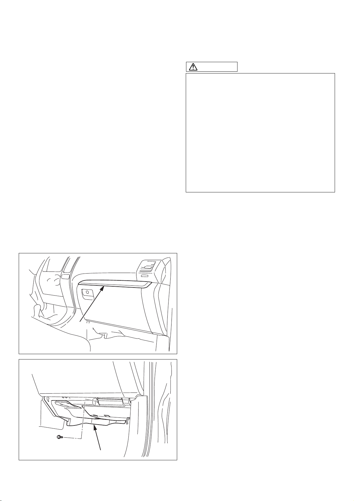
CAUTION
1. Be sure to use the correct oil, refrigerant and
charging/recovery equipment.
2. Before starting installation, read all
“PRECAUTIONS FOR SAFETY
INSTALLATION” thoroughly and follow the
instructions described in it.
3. Before starting installation, remove the (–)
terminal of the battery and ensure seat/floor
covers are in position.
4. Take care not to scratch any parts of the
vehicle.
5. Sort removed bolts and tapping screws into
groups so that they can be reassembled
correctly.
1-1. INSTALLATION INSIDE
PASSENGER COMPARTMENT
BC1891
(1) REMOVAL OF PARTS
(a) Cover
[1] COVER
(b) Under cover
[1] UNDER COVER
BC1892
- 1 -
00502437EA
1. EINBAU
1. INSTALLATION
ACHTUNG
1. Immer sicherstellen, daß das richtige Öl,
Kältemitel und die richtige Ausrüstung zum
Beschicken/Entleeren verwendet wird.
2. Vor dem Beginn des Einbaus alle
"VORSICHTSMASSREGELN ZUR
SICHERHEIT" gründlich durchlesen und zur
Kenntnis nehmen.
3. Vor dem Einbau die negative Batterieklemme () abtrennen und sicherstellen, daß alle Sitz/
Boden-Schutzabdeckungen angebracht sind.
4. Darauf achten, keine Fahrzeugteile zu
zerkratzen.
5. Alle entfernten Schrauben und Blechschrauben
in Gruppen sortiert ablegen, so daß sie beim
Zusammenbau wieder korrekt verwendet
werden können.
1-1. EINBAU IM FAHRGASTRAUM
ATTENTION
1. Assurez-vous d’utiliser l’équipement de
chargement/régénération, réfrigérant et huile
correct.
2. Avant de commencer l’installation, lisez toutes
les « PRECAUTIONS POUR UNE
INSTALLATION EN TOUTE SECURITE »
entièrement et suivre les instructions qui y sont
décrites.
3. Avant de commencer l’installation, enlever la
borne de la batterie (-) et s’assurer que les tapis
de sol et houses de siège sont en position.
4. Faire attention à ne pas érafler aucune partie du
véhicule.
5. Rangez les boulons et vis auto taraudeuse en
groupes de façon à pouvoir les re-assembler
correctement.
1-1. INSTALLATION DANS LE
COMPARTIMENT PASSAGER
ENGLISH - DEUTSCH - FRANÇAIS
(1) AUSBAU VON TEILEN
(a) Abdeckung
1: ABDECKUNG
(b) Bodenabdeckung
1: BODENABDECKUNG
(1) DEPOSE DES PIECES
(a) Protection
1: PROTECTION
(b) Protection inférieure
1: PROTECTION INFERIEURE
- 2 -
00502437EA
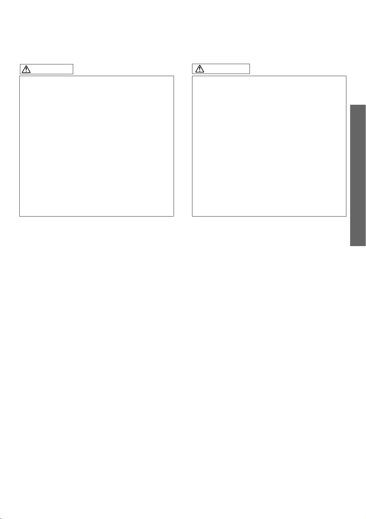
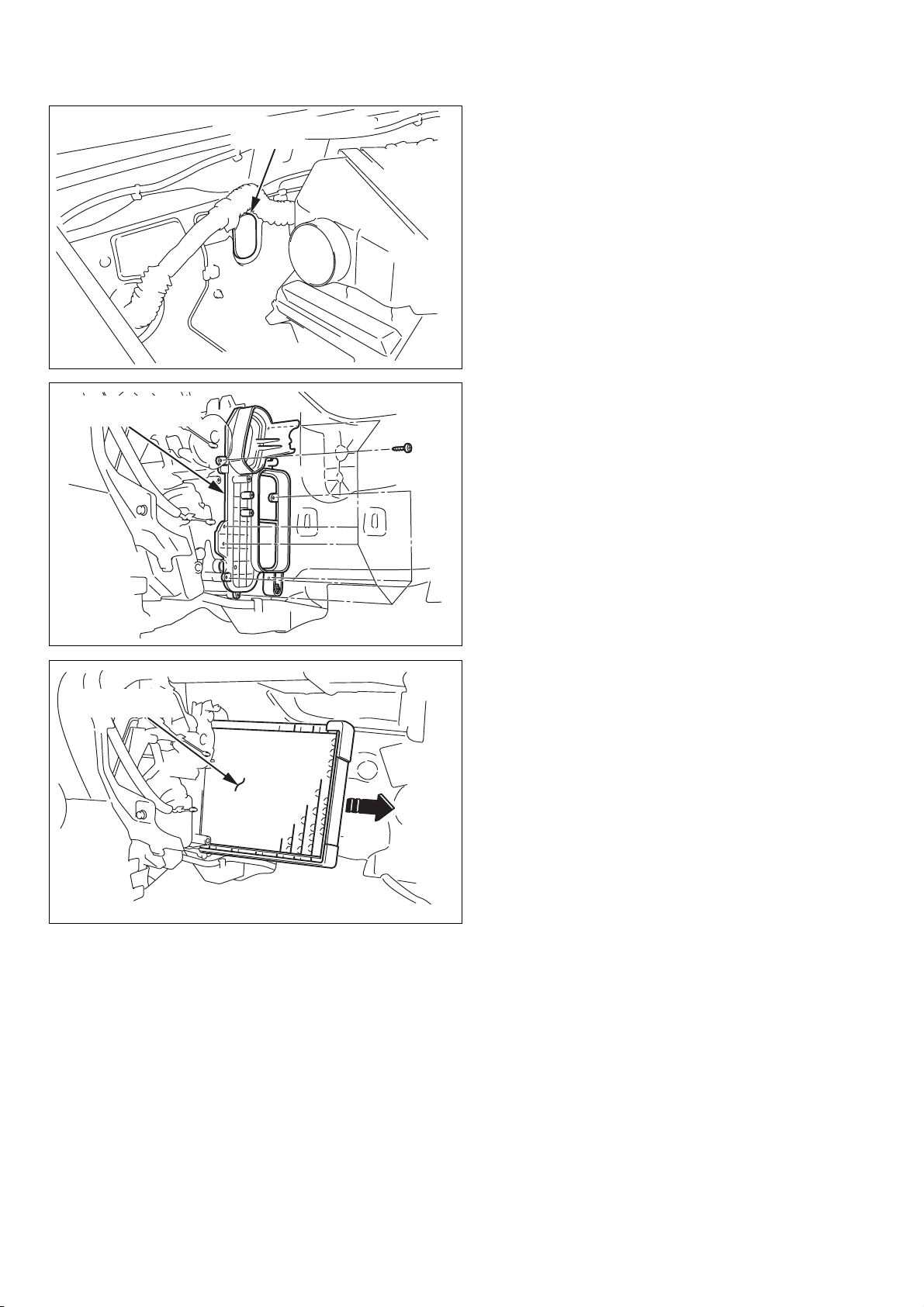
[1] GLOVE BOX
[2] AIR BAG
CONNECTOR
(c) Glove box
CAUTION
Temporarily remove the air bag connector cover
before removing the glove box.
NOTE
Air bag connector is hidden underneath the glove
box cover.
B000499
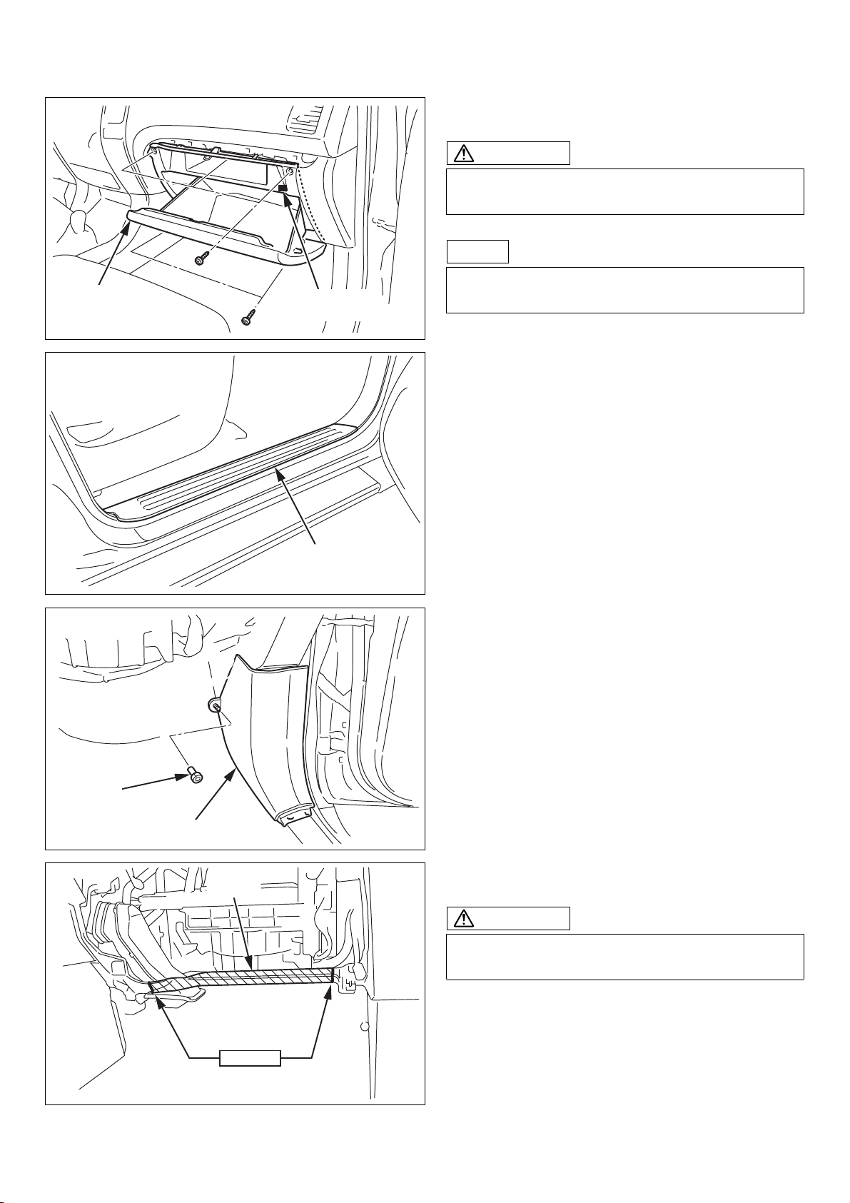
(d) Scuff plate
[2]
CLIP
[1] SIDE COVER
[1] STAY
[1] SCUFF PLATE
BC1894
(e) Side cover
BC1895
(f) Cut out the instrument panel stay.
CAUTION
Be careful not to damage the vehicle harness when
cutting it out.
[2]
CUT OUT
BC1896
- 3 -
00502437EA
(c) Handschuhfach
(c) Boîte à gants
ACHTUNG
Provisorisch die Airbag-Steckerabdeckung
entfernen,bevor das Handschuhfach entfernt wird.
HINWEIS
Der Airbag-Stecker ist unter der
Handschuhfachabdeckung versteckt.
1: HANDSCHUHFACH
2: AIRBAG-STECKER
(d) Scheuerblech
1: SCHEUERBLECH
ATTENTION
Déposez temporairement la protection de connecteur
d’air-bag avant de déposer la boite à gants.
REMARQUE
Le connecteur de l’air-bag est caché sous le
couvercle de la boîte à gants.
1: BOITE A GANTS
2: CONNECTEUR DE L’AIR-BAG
(d) Plaque de protection
1: PLAQUE DE PROTECTION
ENGLISH - DEUTSCH - FRANÇAIS
(e) Seitenabdeckung
1: SEITENABDECKUNG
2: CLIP
(f) Die Instrumentenbrettstrebe ausschneiden.
ACHTUNG
Darauf achten, beim Ausschneiden nicht den
Fahrzeugkabelbaum zu beschädigen.
1: STREBE
2: AUSSCHNEIDEN
(e) Protection latérale
1: PROTECTION LATERALE
2: PINCE
(f) Découpez le potelet du tableau de bord.
ATTENTION
Faire attention à ne pas endommager le faisceau
de câbles du véhicule au moment du découpage.
1: POTELET
2: DECOUPEZ
- 4 -
00502437EA
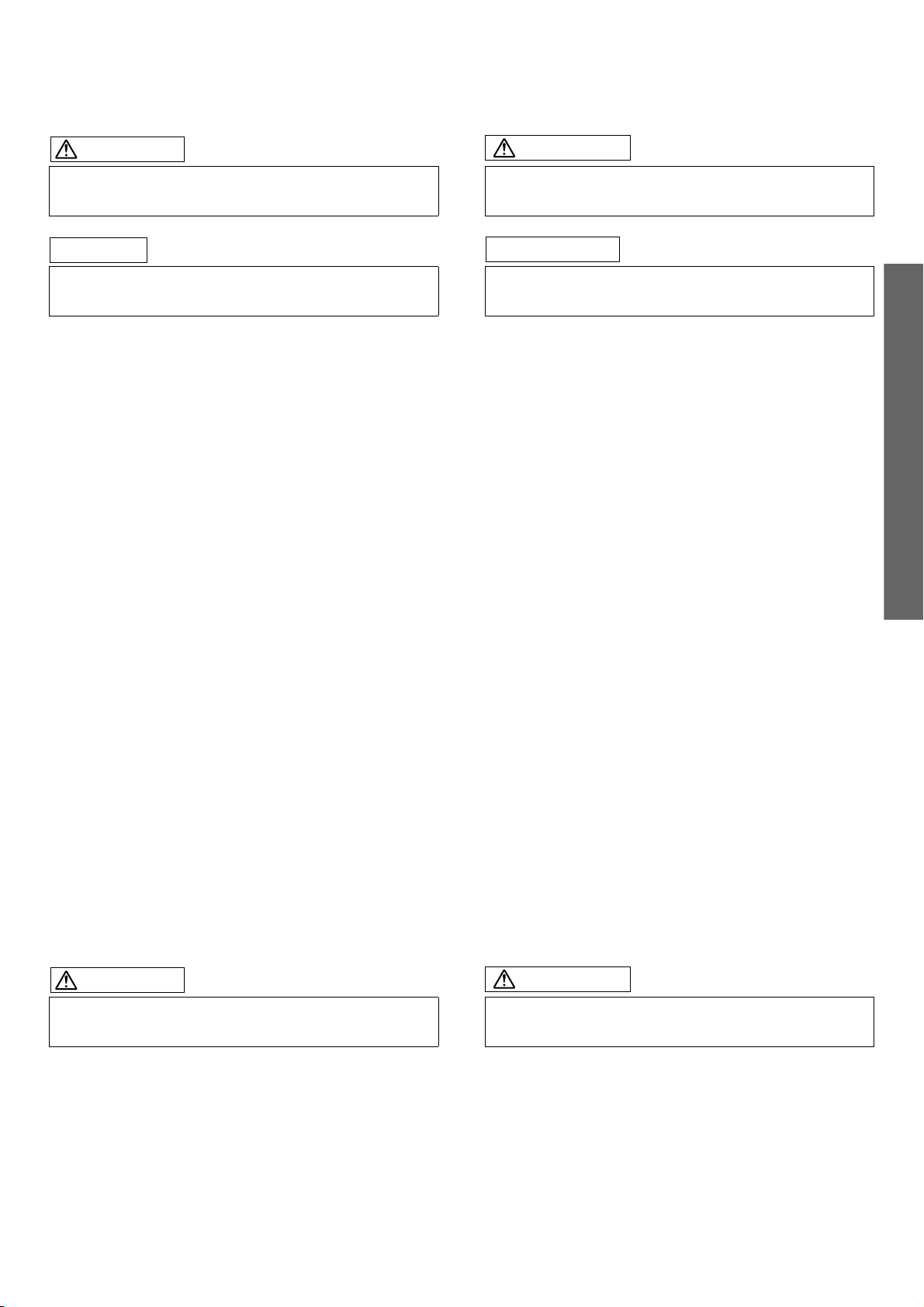
(g) Foot duct
[1] FOOT DUCT
[1] ENGINE CONTROLLER
[2] CONNECTOR BLOCK
[3] CLIP
[1]
BLOWER MOTOR
[2]
CLIP
CONNECTOR
CLIP
[2]
BC1897
(h) Connector block
(i) Engine controller
BC1898
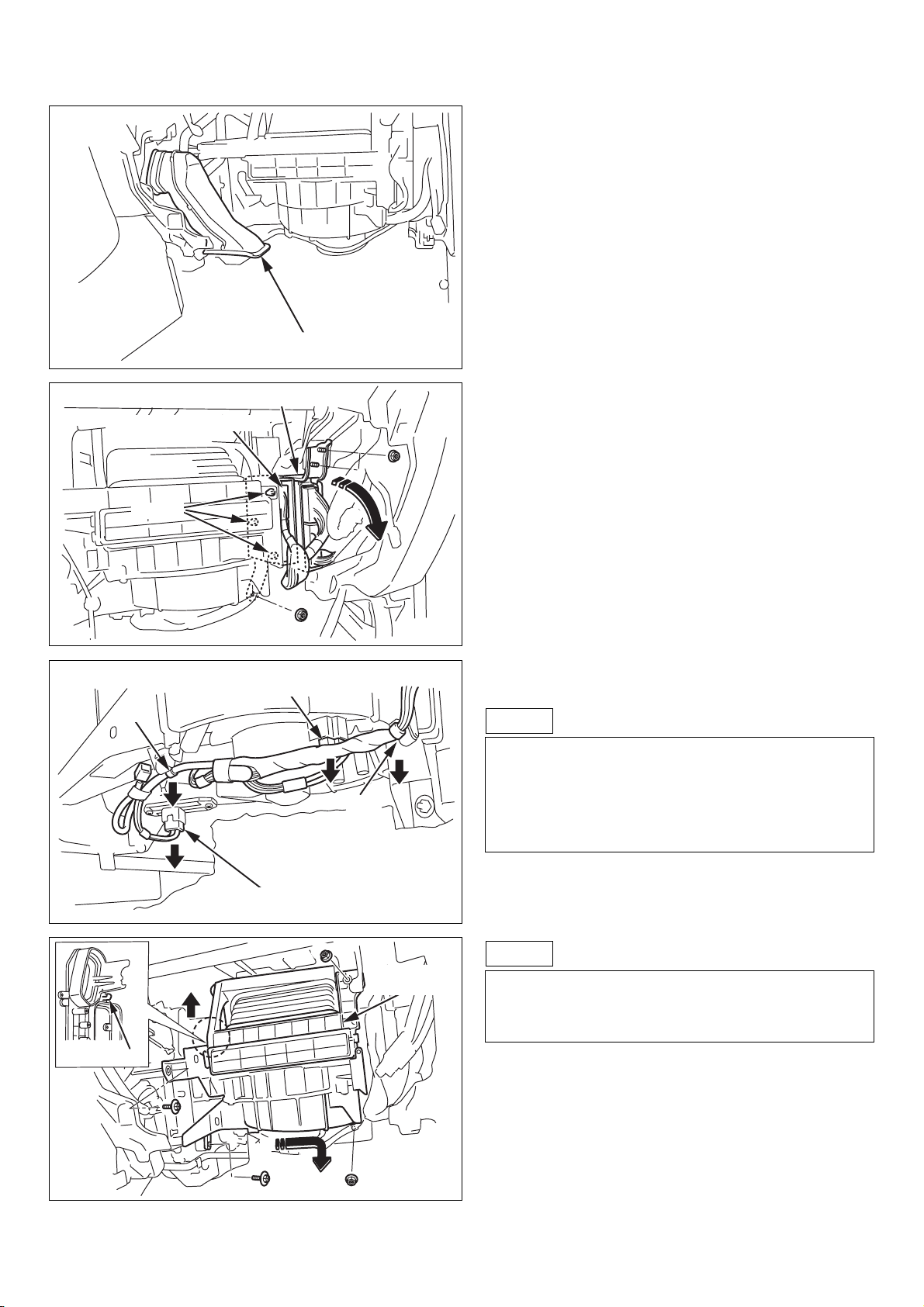
(j) Blower unit
NOTE
1. Disconnect the connection of the blower motor,
blower resistor and FRS/REC servo motor from
the blower unit.
2. Remove vehicle harness clips from the blower
unit.
[2] HOOK
[3]
BLOWER RESISTOR
CONNECTOR
(1)
(2)
(3)
BC1900
[1] BLOWER
UNIT
BC1901
00502437EA
NOTE
1. Lift up the blower unit, then undo the hook.
2. Slide the blower unit to right side.
3. Pull out the blower unit toward you.
- 5 -

(g) Fußschacht
(g) Conduit au pied
1: FUSSSCHACHT
(h) Steckerblock
(i) Motor-Steuereinheit
1: MOTOR-STEUEREINHEIT
2: STECKERBLOCK
3: CLIP
1: CONDUIT AU PIED
ENGLISH - DEUTSCH - FRANÇAIS
(h) Bloc connecteur
(i) Automate moteur
1: AUTOMATE MOTEUR
2: BLOC CONNECTEUR
3: PINCE
(j) Gebläseeinheit
HINWEIS
1. Den Anschluß von Gebläsemotor,
Gebläsewiderstand und Frischluft/UmwälzluftServomotor von der Gebläseeinheit abtrennen.
2. Die Fahrzeugkabelbaumclips von der
Gebläseeinheit entfernen.
1: GEBLÄSEMOTOR-STECKER
2: CLIP
3: GEBLÄSEWIDERSTAND-STECKER
HINWEIS
1. Die Gebläseeinheit anheben, und den Haken
lösen.
2. Die Gebläseeinheit zur rechten Seite schieben.
3. Die Gebläseeinheit nach vorne ziehen.
1: GEBLÄSEEINHEIT
2: HAKEN
(j) Dispositif de soufflerie
REMARQUE
1. Déconnectez la connexion du moteur de
soufflerie, résistance de soufflerie et servo
moteur FRS/REC du dispositif de soufflerie.
2. Déposez les pinces du faisceau de câble du
véhicule du dispositif de soufflerie.
1: CONNECTEUR MOTEUR DE SOUFFLERIE
2: PINCE
3: CONNECTEUR RESISTANCE DE
SOUFFLERIE
REMARQUE
1. Levez le ventilateur, puis défaire le crochet.
2. Faire glisser le dispositif de soufflerie vers le
côté droit.
3. Tirer le dispositif de soufflerie vers vous.
1: DISPOSITIF DE SOUFFLERIE
2: CROCHET
- 6 -
00502437EA
[1] HEATER UNIT
COVER
[1]
ORIGINAL GROMMET
(DISCARD)
(k) Original grommet (Discard)
BC2606
(l) Heater unit cover
[1] SEPARATOR
(DISCARD)
B002306
(m) Separator (Discard)
BC1904
- 7 -
00502437EA

(k) Ursprüngliche Tülle (wegwerfen)
(k) Passe-fils original (jetez)
1: URSPRÜNGLICHE TÜLLE (WEGWERFEN)
(l) Heizungseinheit-Abdeckung
1: HEIZUNGSEINHEIT-ABDECKUNG
1: PASSE-FILS ORIGINAL (JETEZ)
ENGLISH - DEUTSCH - FRANÇAIS
(l) Protection du dispositif de climatisation
1: PROTECTION DU DISPOSITIF DE
CLIMATISATION
(m) Separator (wegwerfen)
1: SEPARATOR (WEGWERFEN)
(m) Séparateur (Jetez)
1: SEPARATEUR (JETEZ)
- 8 -
00502437EA
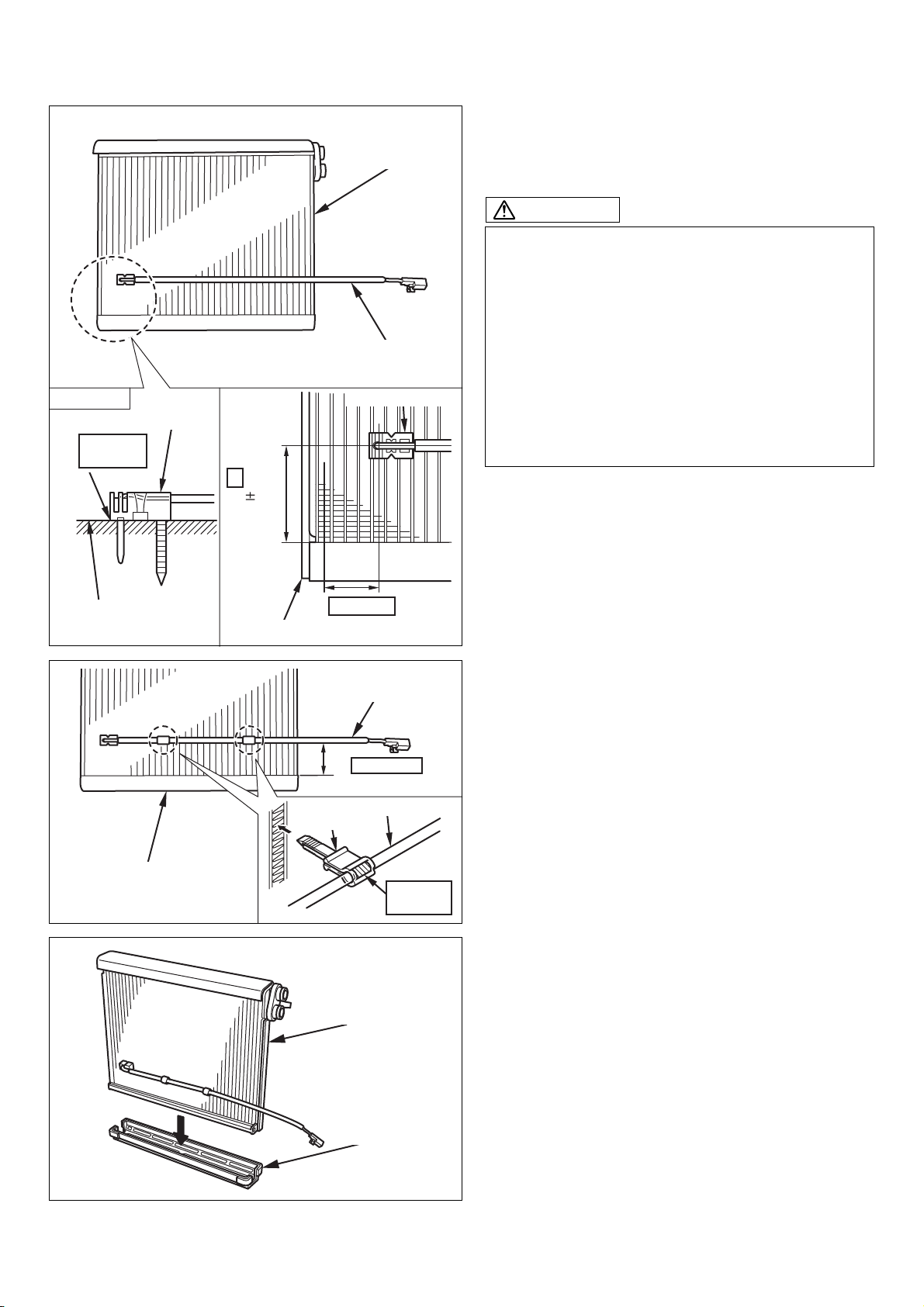
CAUTION
FULL
[4]
CONTACT
[2] THERMISTOR
#
50 5mm50 5mm
[1] EVAPORATOR
[2] THERMISTOR
B001171
[2] THERMISTOR
(2) EVAPORATOR
(a) Insert the thermistor on the evaporator in the
position shown in the figure.
CAUTION
1. Insert the thermistor as far as it goes so that it is
in full contact with the evaporator.
2. To retain it securely, the thermistor is always
inserted into a position only once.
(Once it has been inserted into a location, do
not use that location again.)
3. When reusing the evaporator, shift the
thermistor either up or down 50
(The area marked with the # in the figure.)
4. After the thermistor is inserted, do not apply any
strong forces to the lead wire.
±
5mm.
[1] EVAPORATOR
[1] EVAPORATOR
B001172
[3]
[1] EVAPORATOR
[4] CLAMP
5TH ROW
[2] THERMISTOR
[3]
PAR A LLEL
[2] THERMISTOR
MARKED
[5]
PORTION
[1]
EVAPORATOR
(b) Secure the marked portion of the thermistor with
a clamp to the evaporator, in the position shown
in the figure.
(c) Assemble the under cover to the evaporator.
[2]
UNDER COVER
B001173
00502437EA
- 9 -

(2) VERDAMPFER
(a) Den Thermistor am Verdampfer in der Stellung
einsetzen, wie in der Abbildung gezeigt.
(2) EVAPORATEUR
(a) Insérez le thermistor dans la position de
l'évaporateur montré sur la figure.
ACHTUNG
1. Den Thermistor vollständig einsetzen, so dass
er den Verdampfer berührt.
2. Zur richtigen Befestigung wird der Thermistor
immer nur einmal in eine Position gesetzt.
(Wenn er in eine Position eingesetzt ist,
verwenden Sie diese Position nicht wieder.)
3. Bei Wiederverwendung des Verdampfers den
Thermistor um 50
unten verschieben.
(Der in der Abbildung mit # markierte Bereich.)
4. Nachdem der Thermistor eingesetzt ist, keine
starke Kraft auf den Leitungsdraht einwirken
lassen.
1: VERDAMPFER
2: THERMISTOR
3: 5. REIHE
4: VOLLE BERÜHRUNG
±
5 mm nach oben oder
ATTENTION
1. Insérez le thermistor jusqu'au fond pour adhérer
à l'évaporateur.
2. Pour le retenir en sécurité, la position pour
insérer le thermistor est utilisée seulemnt une
fois.(Ne re-utilisez pas la position où le
thermistor a été inséré une fois.)
3. Quand re-utiliser l’évaporateur, il fault l’insérer à
la position déplacé de 50
(La portion marquée avec # sur la figure.)
4. N'ajoutez pas la force excessive aux fil
conducteur aprés avoir inséré le thermistor.
1: EVAPORATEUR
2: THERMISTOR
3: 5E RANG
4: ADHERENCE
±
5mm verticalment.
ENGLISH - DEUTSCH - FRANÇAIS
(b) Den markierten Teil des Thermistors mit einer
Klammer am Verdampfer in der Stellung sichern,
wie in der Abbildung gezeigt.
1: VERDAMPFER
2: THERMISTOR
3: PARALLEL
4: KLAMMER
5: MARKIERTER TEIL
(c) Die Bodenabdeckung am Verdampfer
anbringen.
1: VERDAMPFER
2: BODENABDECKUNG
(b) Avec une bride, fixez la portion marquée du
thermistor à l'évaporateur montré sur la figure.
1: EVAPORATEUR
2: THERMISTOR
3: PARALLELE
4: COLLIER DE SERRAGE
5: PORTION MARQUEE
(c) Assemblez la protection inférieure à
l’évaporateur.
1: EVAPORATEUR
2: PROTECTION INFERIEURE
- 10 -
00502437EA
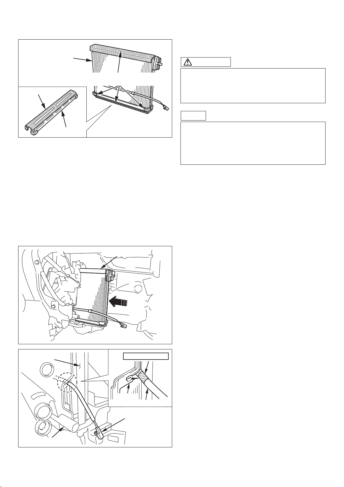
[2] EVAPORATOR
(d) Apply soapy water solution to all urethane foam
on evaporator and under cover.
CAUTION
[4] FOAM PACKING
[3] UNDER COVER
[1] APPLY SOAPY WATER SOLUTION
TO ALL FOAM PACKING
B001174
1. When wetting the foam packing part of
undercover and evaporator, be careful not to
get the water inside of the evaporator.
2. Soapy water solution: neutral type
NOTE
1. Do not remove protective covers on evaporator
prior to applying soapy water solution.
2. To prevent damage to the under cover urethane
foam when inserting the evaporator assembly
into the unit.
[3] EVAPORATOR
[1] EVAPORATOR
[4]
MARKED PORTION
[5] HOOK
[1] THERMISTOR
[1] THERMISTOR
(e) Insert the evaporator assy into the heater unit.
B001175
(f) Insert the marked position of the thermistor on
the hook of the heater unit to secure it.
[2] HEATER UNIT
B001176
- 11 -
00502437EA

(d) Wässrige Seifenlösung auf den gesamten
Urethanschaum auf Verdampfer und
Bodenabdeckung auftragen.
(d) Appliquez une solution d’eau savonneuse à
toute la mousse d’uréthane sur l’évaporateur et
sur le cache inférieur.
ACHTUNG
1. Beim Befeuchten des Schaumpackungsteils an
Unterabdeckung und Verdampfer darauf
achten, kein Wasser in den Verdampfer
eindringen zu lassen.
2. Wässrige Seifenlösung: neutraler Typ
HINWEIS
1. Nicht die Schutzabdeckungen am Verdampfer
vor dem Auftragen der wässrigen Seifenlösung
entfernen.
2. Um Schäden am Urethan der Bodenabdeckung
bein Einsetzen der Verdampferbaugruppe in die
Einheit zu vermeiden.
1: WÄSSRIGE SEIFENLÖSUNG AUF ALLE
SCHAUMPACKUNGEN AUFTRAGEN
2: VERDAMPFER
3: BODENABDECKUNG
4: PACKUNG
ATTENTION
1. Au moment de mouiller la partie garniture de
mousse du cache inferieur et de l'evaporateur,
faites attention a ce que de l'eau ne rentre pas a
l'interieur de l'evaporateur.
2. Solution d’eau savonneuse de type neutre
REMARQUE
1. Ne pas déposer les cashes protecteurs sur
l’évaporateur avant d’avoir appliqué une
solution d’eau savonneuse.
2. Pour eviter d’endommager la mousse d’uréthane
du cache inférieur au moment d’insérer
l’ensemble de l’évaporateur dans l’unité.
1: APPLIQUEZ LA SOLUTION D’EAU SAVONNEUSE
À TOUTE LA GARNITURE DE MOUSSE
2: EVAPORATEUR
3: PROTECTION INFERIEURE
4: GARNITURE
ENGLISH - DEUTSCH - FRANÇAIS
(e) Die Verdampfer-Baugruppe in die
Heizungseinheit einsetzen.
1: VERDAMPFER
(f) Den markierten Teil des Thermistors am Haken
der Heizungseinheit einsetzen, um ihn zu
sichern.
1: THERMISTOR
2: HEIZUNGSEINHEIT
3: VERDAMPFER
4: MARKIERTER TEIL
5: HAKEN
(e) Insérer l’ensemble évaporateur dans le dispositif
de climatisation.
1: EVAPORATEUR
(f) Insérez et fixez la portion marquée du thermistor
au crochet de l'ensemble de chauffage.
1: THERMISTOR
2: DISPOSITIF DE CLIMATISATION
3: EVAPORATEUR
4: PORTION MARQUEE
5: CROCHET
- 12 -
00502437EA
[1] HEATER UNIT
COVER
[1]
EXPANSION
VALVE
B002306
[2]
INSULATOR
(g) Reinstall the heater unit cover.
(3) EXPANSION VALVE & PIPING
(a) Wrap the insulator around the expansion valve
as shown.
[1] EXPANSION VALVE
[1]LIQUID & SUCTION TUBE
BC1910
(b) Install the expansion valve to the evaporator.
BC2603
(c) Route and connect the liquid tube and suction
tube from expansion valve to dash panel.
B000745
- 13 -
00502437EA

(g) Die Heizungseinheit-Seitenabdeckung wieder
einbauen.
(g) Réinstallez la protection de dispositif de
climatisation.
1: HEIZUNGSEINHEIT-ABDECKUNG
(3) EXPANSIONSVENTIL U.
LEITUNGSVERLEGUNG
(a) Den Isolator um das Expansionsventil wickeln,
wie in der Abbildung gezeigt.
1: EXPANSIONSVENTIL
2: ISOLATOR
1: PROTECTION DE DISPOSITIF DE
CLIMATISATION
ENGLISH - DEUTSCH - FRANÇAIS
(3) SOUPAPE DE DETENTE ET CANALISATION
(a) Enrober l’isolant auteur de la soupape de
détente comme montré.
1: SOUPAPE DE DETENTE
2: ISOLANT
(b) Das Expansionsventil am Verdampfer
anbringen.
1: EXPANSIONSVENTIL
(c) Die Kältemittel- und Saugleitung vom
Expansionsventil zum Tretblech verlegen und
anschließen.
1: KÄLTEMITTEL- U. SAUGLEITUNG
(b) Installez la soupape de détente à l’évaporateur.
1: SOUPAPE DE DÉTENTE
(c) Acheminez et connectez le tube de liquide et
d'aspiration depuis la soupape d'expansion au
tablier.
1: TUBE DE LIQUIDE ET D'ASPIRATION
- 14 -
00502437EA

[1] EXPANSION VALVE
[3]LIQUID&SUCTION TUBE
[2]
HEX SOCKET
BOLT(M5 x 53)
B000746
(d) Fasten the liquid tube and suction tube to the
expansion valve using two hexagon socket
bolts.
Tightening Torque
3.5 N•m (35 kgf•cm, 2.6 ft•lbf)
[1]
COVER
[2]
TAPPING SCREW
BOLT(M5 x 12)
[1]
GROMMET
SEE :A
[3]
COVER
[1]
SEE :A
[3]
HEATER
[4]
UNIT
(e) Install the cover to the heater unit using the
tapping screw.
NOTE
Fasten the cover guide edge as shown. (SEE:A)
BC1913
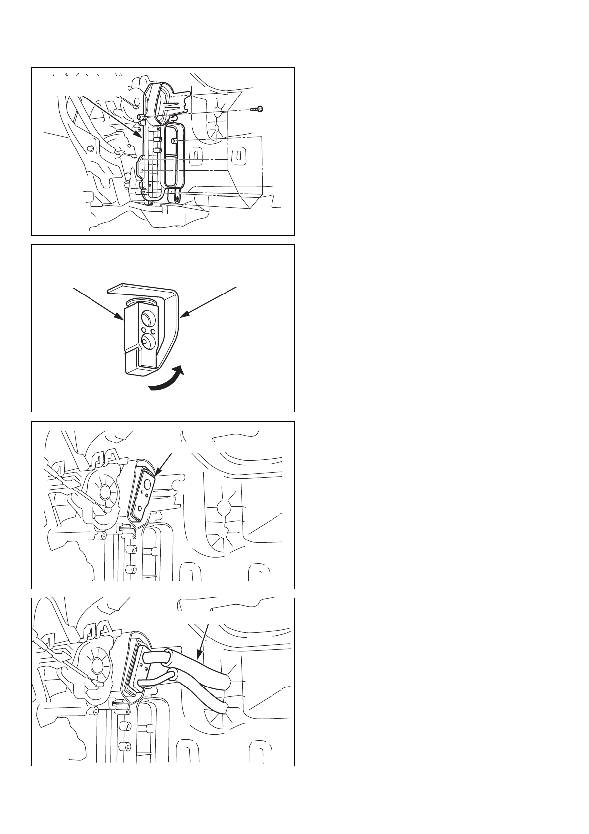
(4) GROMMET
(a) Install the grommet to the bulkhead.
[1] VEHICLE HARNESS (20-P)
[4]
ENGINE
CONTOROLLER
BC2607
[2] A/C AMPLIFIER
[3]
BOLT (M6 x 14)
B000632
00502437EA
(5) A/C AMPLIFIER
(a) Install the A/C amplifier to the engine controller
using a bolt.
(b) Connect the vehicle harness (20-P) to the A/C
amplifier.
- 15 -

(d) Die Kältemittel- und Saugleitung am
Expansionsventil mit Bügel und zwei
Innensechskant-Steckschrauben befestigen.
(d) Attachez le tube de liquide et d'aspiration à la
soupape d'expansion en utilisant 2 douilles
hexagonales.
Anzugsdrehmoment:
3,5 N•m (35 kgf•cm)
1: EXPANSIONSVENTIL
2: INNENSECHSKANT-STECKSCHRAUBE (M5 X
L53)
3: KÄLTEMITTEL- U. SAUGLEITUNG
(e) Die Abdeckung an der Heizungseinheit mit der
Blechschraube anbringen.
HINWEIS
Die Abdeckungsführungskante befestigen, wie in
der Abbildung gezeigt. (SICHT:A)
1: ABDECKUNG
2: BLECHSTECKSCHRAUBE (M5 X L12)
3: SICHT: A
4: HEIZUNGSEINHEIT
Couple de serrage
3,5 N•m (35 kgf•cm, 2,6 ft•lbf)
1: SOUPAPE DE DÉTENTE
2: BOULON A SIX PANS CREUX (M5 x L53)
3: TUBE DE LIQUIDE ET D'ASPIRATION
(e) Installez la protection au dispositif de
climatisation en utilisant une vis auto
taraudeuse.
REMARQUE
Serrez le bord du guide de couvercle comme
montré. (VOIR:A)
1: COUVERCLE
2: VIS AUTOTARAUDEUSE BOULON (M5xL12)
3: VOIR : A
4: DISPOSITIF DE CLIMATISATION
ENGLISH - DEUTSCH - FRANÇAIS
(4) TÜLLE
(a) Die Tülle in der Motortrennwand anbringen.
1: TÜLLE
(5) KLIMAANLAGEN-VERSTÄRKER
(a) Den Klimaanlagen-Verstärker mit einer
Steckschraube an der Motor-Steuereinheit
anbringen.
(b) Den Fahrzeugkabelbaum (20-P) am
Klimaanlagen-Verstärker anschließen.
1: FAHRZEUGKABELBAUM (20-P)
2: KLIMAANLAGEN-VERSTÄRKER
3: STECKSCHRAUBE (M6 X L14)
4: MOTOR-STEUEREINHEIT
(4) PASSE-FILS
(a) Installez le passe-fils à la cloison
1: PASSE-FILS
(5) AMPLIFICATEUR DU CLIMATISEUR
(a) Installez l’amplificateur du climatiseur à
l’automate du moteur en utilisant un boulon.
(b) Connectez le faisceau de câble du véhicule (20-
fiches) à l’amplificateur du climatiseur.
1: FAISCEAU DE CABLE DU VEHICULE
(20 fiches)
2: AMPLIFICATEUR DU CLIMATISEUR
3: BOULON (M6 x L14)
4: AUTOMATE DU MOTEUR
- 16 -
00502437EA

[1] BLOWER
UNIT
(6) REINSTALLATION
(a) Blower unit
B001177
[1] ENGINE CONTROLLER
[2] CONNECTOR BLOCK
[3] CLIP
[1]
BLOWER MOTOR
[2]
CLIP
CONNECTOR
(b) Engine controller
(c) Connector block
BC1917
NOTE
1. Reconnect the blower motor, blower resistor
and FRS/REC servo motor connectors to the
blower unit.
2. Secure two vehicle harness clips to the blower
unit.
CLIP
[2]
[3]
BLOWER RESISTOR
CONNECTOR
BC1919
- 17 -
00502437EA

(6) WIEDEREINBAU
(a) Gebläseeinheit
(6) REINSTALLATION
(a) Dispositif ventilateur
1: GEBLÄSEEINHEIT
(b) Motor-Steuereinheit
(c) Steckerblock
1: MOTOR-STEUEREINHEIT
2: STECKERBLOCK
3: CLIP
1: DISPOSITIF VENTILATEUR
ENGLISH - DEUTSCH - FRANÇAIS
(b) Automate du moteur
(c) Bloc de connexion
1: AUTOMATE DU MOTEUR
2: BLOC DE CONNEXION
3: PINCE
HINWEIS
1. Die Stecker von Gebläsemotor,
Gebläsewiderstand und Frischluft/UmwälzluftServomotor erneut an der Gebläseeinheit
anschließen.
2. Zwei Fahrzeugkabelbaumclips an der
Gebläseeinheit anbringen.
1: GEBLÄSEMOTOR-STECKER
2: CLIP
3: GEBLÄSEWIDERSTAND-STECKER
REMARQUE
1. Reconnectez les connexions du moteur de
soufflerie, résistance de soufflerie et servo
moteur FRS/REC au dispositif de soufflerie.
2. Attachez deux pinces du faisceau de câble du
véhicule au dispositif de soufflerie.
1: CONNECTEUR MOTEUR DE SOUFFLERIE
2: PINCE
3: CONNECTEUR RESISTANCE DE
SOUFFLERIE
- 18 -
00502437EA
 Loading...