


Toshiba XV636-32, XV636-37, XV636-42, XV636-46, XV635-42 User Manual
...
TOSHIBA
XV***
Digital
Series
Contents
SETTING UP |
|
Safety precautions – Some do’s and don't for you to be aware of |
4 |
Installation and important information |
5 |
The remote control – an at-a-glance guide |
6 |
Connecting external equipment – a guide to connecting external equipment to the back of the television |
7 |
REGZA-LINK connections |
8 |
Connecting an HDMI or DVI device to the HDMI input |
9 |
Connecting a computer – connecting a computer to the HDMI terminal on the back of the television |
10 |
Acceptable signals through HDMI terminals |
11 |
Connecting a computer – connecting a computer to the RGB/PC terminal on the back of the television |
12 |
Acceptable PC signals through the PC terminal |
13 |
Using the controls – switching on the television, standby, using the remote control, using the controls on |
|
the television, headphone socket |
14 |
TUNING THE TELEVISION |
|
Tuning the television for the first time |
15 |
Setting antenna or cable |
16 |
DTV auto tuning, manual tuning, manual tuning for DVB-C |
17 |
DTV location, auto channel update, DVB character set, Analogue switch off |
18 |
DTV sorting channels, skipping channels |
19 |
ATV manual tuning, broadcast system |
20 |
ATV skipping channels, sorting channel positions |
21 |
CONTROLS AND FEATURES |
|
General controls – selecting programme positions |
22 |
Stereo and bilingual transmissions – stereo/mono or dual language broadcasts |
22 |
Time display (ATV only) |
22 |
Sound controls – volume, sound mute |
22 |
Quick menu |
22 |
Sound settings – dual, bass, treble and balance, advanced sound settings (surround, voice enhancement, |
|
dynamic bass boost, external woofer), Dolby Volume® |
23 |
Sound settings – dynamic range control (DTV only), audio level offset, headphone settings, |
|
audio description |
24 |
Widescreen viewing |
25 |
Picture controls – picture position (ATV only), picture mode, picture preferences (contrast, brightness, |
|
colour, tint, sharpness) |
27 |
Picture controls – reset, backlight, 3D colour management, base colour adjustment |
28 |
Picture controls – colour temperature, auto brightness sensor settings, active backlight control, |
|
black/white level |
29 |
Picture controls – static gamma, MPEG noise reduction (MPEG NR), digital noise reduction (DNR), |
|
Resolution + |
30 |
Picture controls – Active Vision M100, film stabilization, expert mode, reset |
31 |
Picture controls – control visualization, panel lock (disabling the buttons on the television), |
|
automatic format (widescreen) |
32 |
Picture controls – 4:3 stretch, blue screen, side panel adjustment, Toshiba illumination, picture still |
33 |
DTV programme timer |
34 |
Timers – on timer (setting the television to turn on) |
34 |
Timers – cancelling the on timer, sleep timer (setting the television to turn off) |
35 |
DTV on-screen information |
36 |
DTV programme guide |
37 |
DTV Settings – setting the PIN code, parental control, locking channels |
38 |
DTV Settings – subtitles, audio languages, common interface |
39 |
2
Contents (continued)
Software Upgrade – auto upgrade, searching for new software, software licences, system information, |
|
reset TV |
40 |
Media player – auto start, opening media player automatically, opening media player from the menu |
41 |
Media player – multiview, single view, slideshow, interval time and repeat |
42 |
Media player – playing movies, picture size and repeat, DivX® VOD |
43 |
Media player – playing music, repeat mode |
44 |
Media player – setting up the photo frame feature |
45 |
PC settings for RGB/PC connections – picture position, clock phase, sampling clock, reset |
46 |
REGZA-LINK controls – general information, input source selection |
47 |
REGZA-LINK menus – enable REGZA-LINK |
48 |
REGZA-LINK menus – TV auto power, auto standby, amplifier control, speaker preference |
49 |
Input selection and AV connections – input selection, external input skip, input signal selection, PC audio 50
Input selection and AV connections – HDMI1 Audio, HDMI settings (lip sync, INSTAPORT™, RGB range), |
|
digital output |
51 |
TEXT SERVICES |
|
ATV text services – selecting modes, general information, Auto and LIST modes |
52 |
ATV text services – control buttons |
53 |
DTV interactive services – general information |
53 |
PROBLEM SOLVING |
|
Questions and Answers – answers to some common queries including manual fine tuning, colour system |
54 |
INFORMATION |
|
Disposal |
58 |
Specifications and Accessories – technical information about the television, supplied accessories |
59 |
3

Safety Precautions
This equipment has been designed and manufactured to meet international safety standards but, like any electrical equipment, care must be taken to obtain the best results and for safety to be assured. Please read the points below for your own safety. They are of a general nature, intended to help with all electronic consumer products and some points may not apply to the goods you have just purchased.
Air Circulation
Leave more than 10cm clearance around the television to allow adequate ventilation. This will prevent overheating and possible damage to the television. Dusty places should also be avoided.
Heat Damage
Damage may occur if the television is left in direct sunlight or near a heater. Avoid places subject to extremely high temperatures or humidity. Place in a location where the temperature remains between 5°C (41°F) min. and 35°C (94°F) max.
Mains Supply
The mains supply required for this equipment is 220-240v AC 50/60Hz. Never connect to a DC supply or any other power source. DO ensure that the television is not standing on the mains lead. DO NOT cut off the mains plug from this equipment, this incorporates a special Radio Interference Filter, the removal of which will impair its performance.
In the UK, the fuse fitted in the plug is approved by ASTA or BSI to BS1362. It should only be replaced by a correctly rated and approved type and the fuse cover must be refitted.
IF IN DOUBT PLEASE CONSULT A COMPETENT ELECTRICIAN.
Do
DO read the operating instructions before you attempt to use the equipment.
DO ensure that all electrical connections (including the mains plug, extension leads and inter-connections between pieces of equipment) are properly made and in accordance with the manufacturers’ instructions. Switch off and withdraw the mains plug before making or changing connections.
DO consult your dealer if you are ever in doubt about the installation, operation or safety of your equipment.
DO be careful with glass panels or doors on equipment.
DO NOT REMOVE ANY FIXED COVERS AS THIS WILL EXPOSE DANGEROUS AND 'LIVE' PARTS.
THE MAINS PLUG IS USED AS A DISCONNECTING DEVICE AND THEREFORE SHOULD BE READILY OPERABLE.
Do not
DO NOT obstruct the ventilation openings of the equipment with items such as newspapers, tablecloths, curtains, etc. Overheating will cause damage and shorten the life of the equipment.
DO NOT allow electrical equipment to be exposed to dripping or splashing or objects filled with liquids, such as vases, to be placed on the equipment.
DO NOT place hot objects or naked flame sources, such as lighted candles or nightlights on, or close to equipment. High temperatures can melt plastic and lead to fires.
DO NOT use makeshift stands and NEVER fix legs with wood screws. To ensure complete safety, always fit the manufacturers’ approved stand, bracket or legs with the fixings provided according to the instructions.
DO NOT leave equipment switched on when it is unattended, unless it is specifically stated that it is designed for unattended operation or has a standby mode. Switch off by withdrawing the plug, make sure your family know how to do this. Special arrangements may need to be made for people with disabilities.
DO NOT continue to operate the equipment if you are in any doubt about it working normally, or it is damaged in any way – switch off, withdraw the mains plug and consult your dealer.
WARNING – excessive sound pressure from earphones or headphones can cause hearing loss.
ABOVE ALL – NEVER let anyone, especially children, push or hit the screen, push anything into holes, slots or any other openings in the case.
NEVER guess or take chances with electrical equipment of any kind – it is better to be safe than sorry.
4
Installation and important information
Where to install
Locate the television away from direct sunlight and strong lights, soft, indirect lighting is recommended for comfortable viewing. Use curtains or blinds to prevent direct sunlight falling on the screen.
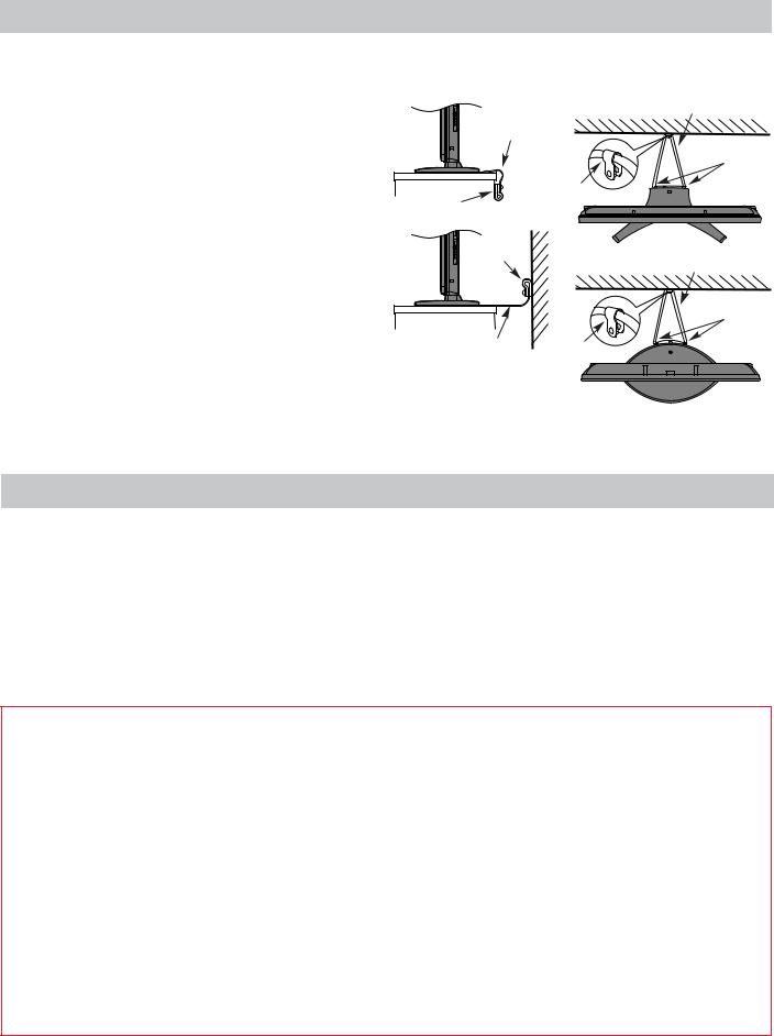
Place the TV on a stable, level surface that can support the weight of the TV. In order to maintain stability and prevent it falling over, secure the TV to the level surface using the strap located under the table top stand, or to a wall using a sturdy tie to the clip on the back of the table top stand.
The LCD display panels are manufactured using an extremely high level of precision technology, however sometimes some parts of the screen may be missing picture elements or have luminous spots. This is not a sign of a malfunction.
Make sure the television is located in a position where it cannot be pushed or hit by objects, as pressure will break or damage the screen, and that small items cannot be inserted into slots or openings in the case.
Cleaning the screen and cabinet…
Side View |
Top View |
Fixing |
Sturdy tie (short as possible) |
|
|
strap |
|
|
Stand |
|
clip |
‘P’ Clip |
‘P’ Clip |
|
|
‘P’ Clip |
Sturdy tie (short as possible) |
|
|
|
Stand |
|
clip |
Fixing strap |
‘P’ Clip |
|
Stand style is dependant on the model
Turn off the power, clean the screen and cabinet with a soft, dry cloth. We recommend that you do not use any proprietary polishes or solvents on the screen or cabinet as this may cause damage.
Please take note
The digital reception function of this television is only effective in the countries listed in Country in the SETUP menu. Depending on the country/area some of this television’s functions may not be available. Reception of future additional or modified services can not be guaranteed with this television.
If stationary images generated by 4:3 broadcasts, text services, channel identification logos, computer displays, video games, on screen menus, etc. are left on the television screen for any length of time they could become conspicuous, it is always advisable to reduce both the brightness and contrast settings.
Very long, continuous use of the 4:3 picture on a 16:9 screen may result in some retention of the image at the 4:3 outlines, this is not a defect of the LCD TV and is not covered under the manufacturers warranty. Regular use of other size modes (eg. Superlive) and varying the “side panel” brightness (if available on the model) will prevent permanent retention.
EXCLUSION CLAUSE
Toshiba shall under no circumstances be liable for loss and/or damage to the product caused by:
i)fire;
ii)earthquake;
iii)accidental damage;
iv)intentional misuse of the product;
v)use of the product in improper conditions;
vi)loss and/or damage caused to the product whilst in the possession of a third party;
vii)any damage or loss caused as a result of the owner’s failure and/or neglect to follow the instructions set out in the owner’s manual;
viii)any loss or damage caused directly as a result of misuse or malfunction of the product when used simultaneously with associated equipment;
Furthermore, under no circumstances shall Toshiba be liable for any consequential loss and/or damage including but not limited to the following, loss of profit, interruption of business, the loss of recorded data whether caused during normal operation or misuse of the product.
NOTE: A Toshiba wall bracket or stand, where available, must be used to maintain the product’s BEAB approval.
5
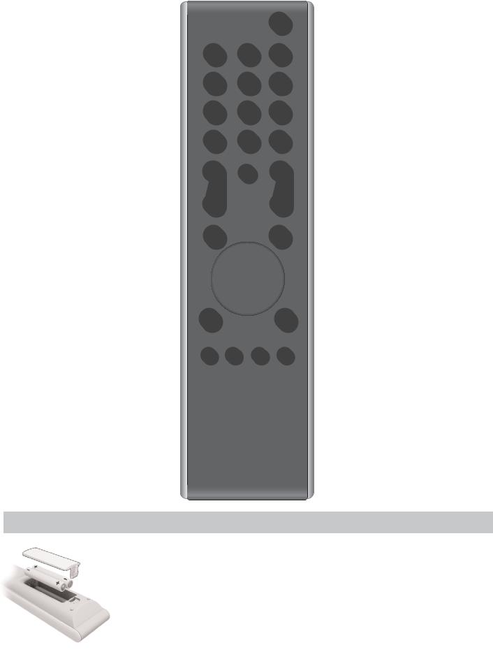
The remote control
Simple at-a-glance reference of your remote control.
To select mode |
For On/Standby mode |
Number buttons 

Audio description
To mute the sound
To alter the volume 

To display the digital on-screen
Programme Guide
To display on-screen information
Text and interactive service control buttons
Digital subtitles
Stereo/bilingual transmissions
To switch between ATV (analogue
TV) and DTV (digital TV)
To display on-screen menus
REGZA-LINK or DVD mode: pressm/llrto PAUSE/STEP press rto PLAY
press qto REWIND
presssto FAST FORWARD presswto EJECT
presspto STOP
press lqto SKIP-REWIND presssl to SKIP-FORWARD
To select input from external sources, 
 analogue or digital TV.
 To change programme positions and text pages

 Quick menu

 To exit Menus
When using menus the arrows move the cursor on the screen up, down, left or right. OK to confirm your selection
To return to the previous menu Widescreen viewing
To call up text services in analogue mode and interactive services in digital mode
When in TV mode:
MENU To display on-screen menus
ATV/DTV To switch between ATV (analogue
|
TV) and DTV (digital TV) |
LIST |
To switch between TV and Radio lists |
u |
in DTV mode |
Still picture |
|
8/9 |
Analogue time display |
When using the Programme Guide: |
|
lq – 24 hours |
|
sl |
+ 24 hours |
q – 1 page s + 1 page
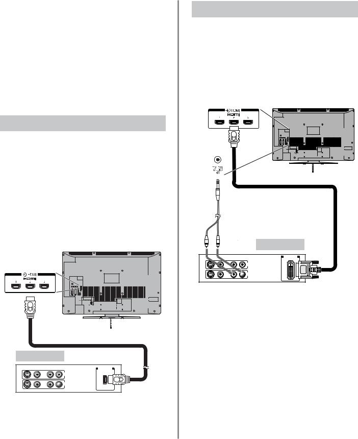
Inserting batteries and effective range of the remote
Remove the back cover to reveal the battery compartment and make sure the batteries are inserted the right way round. Suitable battery types for this remote are AAA, IEC R03 1.5V.
Do not combine a used, old battery with a new one or mix battery types. Remove discharged batteries immediately to prevent acid from leaking into the battery compartment. Dispose of them in accordance with the disposal instructions in this manual. Warning: batteries must not be exposed to excessive heat such as sunshine, fire or the like.
The performance of the remote control will deteriorate beyond a distance of five metres or outside an angle of 30 degrees from the centre of the television. If the operating range becomes reduced the batteries may need replacing.
6

Connecting external equipment
Before connecting any external equipment, turn off all main power switches. If there is no switch remove the mains plug from the wall socket.
OPTICAL DIGITAL AUDIO OUTPUT 


HDMI INPUT SOCKETS 
COMPONENT VIDEO INPUT (EXT3)
SCART 2 (EXT2)
|
|
|
|
SCART 1 (EXT1) |
|
|
|
|
|
|
|
|
|
|
|
|
|
|
|
|||
|
|
|
|
|
|
|
|
|
|
|
|
|
|
|
|
|
|
|
||||
|
|
|
|
|
|
|
|
|
|
|
|
|
|
|
|
|||||||
|
|
|
|
|
|
|
|
|
|
|
|
|||||||||||
|
|
|
|
|
|
|
|
|
|
|
|
|
|
|
|
|
|
|
||||
* |
|
|
|
could |
|
|
|
|
|
|
|
|
|
|
|
|
|
|
|
|
|
|
|
|
|
|
|
|
|
|
|
|
|
|
|
|
|
|
|
|
|
|
|||
|
|
|
|
|
|
|
|
|
|
|
|
|
|
|
|
|
|
|
|
|||
|
|
|
|
|
|
|
|
|
|
|
|
|
|
|
|
|
|
|
|
|||
|
|
|
|
|
|
|
|
|
|
|
|
|
|
|
|
|
|
|
|
|||
|
|
|
|
|
|
|
|
|
|
|
|
|
|
|
|
|
|
|
|
|||
|
|
|
|
|
|
|
|
|
|
|
|
|
|
|
|
|
|
|
|
|||
|
|
|
|
|
|
|
|
|
|
|
|
|
|
|
|
|
|
|
|
|||
|
|
|
|
|
|
|
|
|
|
|
|
|
|
|
|
|
|
|
|
|||
|
|
|
|
|
|
|
|
|
|
|
|
|
|
|
|
|
|
|
|
|||
|
|
|
|
|
|
|
|
|
|
|
|
|
|
|
|
|
|
|
|
|||
|
|
|
|
|
|
|
|
|
|
|
|
|
|
|
|
|
|
|
|
|||
|
|
|
|
|
|
|
|
|
|
|
|
|
|
|
|
|
|
|
|
|||
|
|
|
|
|
|
|
|
|
|
|
|
|
|
|
|
|
|
|
|
|||
|
|
|
|
|
|
|
|
|
|
|
|
|
|
|
|
|
|
|
|
|||
|
|
|
|
|
|
|
|
|
|
|
|
|
|
|
|
|
|
|
|
|||
|
|
|
|
|
|
|
|
|
|
|
|
|
|
|
|
|
|
|
|
|||
|
|
|
|
|
|
|
|
|
|
|
|
|
|
|
|
|
|
|
|
|||
|
|
|
|
|
|
|
|
|
|
|
|
|
|
|
|
|
|
|
|
|||
|
|
|
|
|
|
|
|
|
|
|
|
|
|
|
|
|
|
|
|
|||
|
|
|
|
|
|
|
|
|
|
|
|
|
|
|
|
|
|
|
|
|||
|
|
|
|
|
|
|
|
|
|
|
|
|
|
|
|
|||||||
|
|
|
|
|
|
|
|
|
|
|
|
|
|
|
|
|
|
|
|
|||
|
|
|
|
|
|
|
|
|
|
|
|
|
|
|
|
|
|
|
|
|||
|
|
|
|
|
|
|
|
|
|
|
|
|
|
|
|
|||||||
a decoder |
|
|
|
|
|
|
|
|
|
|
|
|
|
|
|
|
|
|
||||
be Digital |
Satellite |
|
|
|
|
|
|
|
|
|
|
|
|
|
|
|
||||||
|
|
|
|
|
|
|
|
|
|
|
|
|
|
|
|
|||||||
or any other |
|
. |
|
|
|
|
|
|
|
|
|
|
|
|
|
|
|
|
|
|||
|
|
|
|
|
|
|
|
|
|
|
|
|
|
|
|
|
|
|||||
|
|
|
|
|
|
|
|
|
|
|
|
|
|
|
|
|
|
|||||
|
|
|
|
|
|
|
|
|
|
|
|
|
|
|
|
|
|
|
|
|
|
|
compatible |
decoder |
|
|
|
|
|
|
|
||||||||||||||
|
|
|
|
|
|
|
|
|
|
|
|
|
|
|
|
|
|
|
|
|||
Decoder*
Media Recorder
Aerial cables:
Connect the aerial to the socket on the rear of the television. If you use a decoder* and/or a media recorder it is essential that the aerial cable is connected through the decoder and/or through the media recorder to the television.
SCART leads:
Connect the video recorder IN/OUT socket to the television. Connect the decoder TV socket to the television. Connect the media recorder SAT socket to the decoder MEDIA REC. socket.
Before running Auto tuning put your decoder and media recorder to Standby.
The phono sockets alongside the COMPONENT VIDEO INPUT sockets will accept L and R audio signals.
The Digital Audio Output socket enables the connection of a suitable surround sound system. NOTE: this output is always active.
HDMI (High-Definition Multimedia Interface) is for use with a DVD, decoder or electrical equipment with digital audio and video output. It is designed for best performance with 1080i and 1080p high-definition video signals but will also accept and display VGA, 480i, 480p, 576i, 576p and 720p signals.
HDMI, the HDMI logo and High-Definition Multimedia Interface are trademarks or registered trademarks of HDMI Licensing, LLC.
INSTAPORT™ and INSTAPORT logo are trademarks of Silicon Image, Inc. in the United States and other countries.
 FIXING STRAP CABLE HOLDER
|
The |
|
can be |
cable holders |
|
|
used for aerial, |
|
media |
|
|
|
recorder and |
|
audio cables. |
||
use as |
Do not |
|
|
handles and |
|
remove |
|
|
|
all cables |
|
before |
|
|
|
moving the |
|
television. |
|
|
PLEASE NOTE: Although this television is able to connect to HDMI equipment it is possible that some equipment may not operate correctly.
A wide variety of external equipment can be connected to the back of the television, therefore the relevant owners manuals for all additional equipment must be referred to.
We recommend SCART 1 for a decoder and SCART 2 for a media recorder.
If connecting S-VIDEO equipment, set the INPUT for EXT2. See page 50.
If the television automatically switches over to monitor external equipment, return to normal television by pressing the desired programme position button. To recall external equipment, press Bto select between TV, EXT1, EXT2, EXT3C, HDMI1, HDMI2, HDMI3, HDMI4 (Model dependant) or PC.
When the external input mode is selected whilst viewing DTV mode the SCART socket will not output video/audio signals. The SCART output will also be muted in EPG mode.


 Manufactured under license from Dolby Laboratories.
Dolby and the double-D symbol are registered trademarks of
Dolby Laboratories.
Manufactured under licence from Audyssey Laboratories U.S. and  foreign patents pending.
Audyssey EQ is a registered trademark of Audyssey Laboratories.
7

REGZA-LINK connections
The basic functions of connected audio/video equipment can be controlled using the televisions remote control if a REGZA-LINK compatible device is connected.
The back of your television
AV amplifier |
Playback equipment |
HDMI IN HDMI OUT |
HDMI OUT |
Playback equipment
HDMI OUT
NOTE: It is recommended that for correct operation all audio/video devices are connected using HDMI cables branded with the HDMI logo (  ). If several devices are connected, the REGZA-LINK feature may not operate properly.
After connecting the equipment use the REGZA-LINK menus to setup the desired options. The connected equipment must also be set. For details see the operation manual for each connected device.
NOTE: The REGZA-LINK feature uses CEC Technology as regulated by the HDMI standard. This feature is limited to models incorporating Toshiba’s REGZA-LINK. However, Toshiba is not liable for those operations. Refer to individual instruction manuals for compatability information.
8
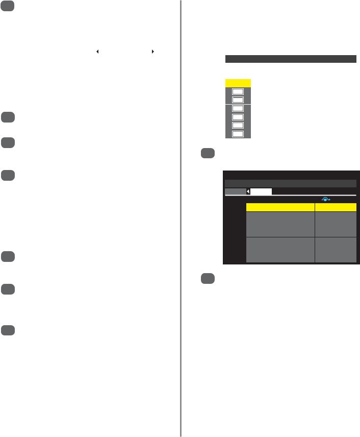
Connecting an HDMI or DVI device to the HDMI input
The HDMI input on the television receives digital audio and uncompressed digital video from an HDMI source device, or uncompressed digital video from a DVI (Digital Visual Interface) source device.
This input is designed to accept HDCP (High-Bandwidth Digital-Content Protection) programme material in digital form from EIA/CEA-861-D–compliant [1] consumer electronic devices (such as a set-top box or DVD player with HDMI or DVI output). For acceptable signal formats, see page 11.
NOTE: Some early HDMI equipment may not work properly with the latest HDMI TV, due to the adoption of a new standard. Please unplug the HDMI cable first and then try setting the options in HDMI Settings to Off. See page 51.
Supported Audio format: Linear PCM, sampling rate 32/44.1/48kHz.
Connecting an HDMI Ddevice
Connect an HDMI cable (type A connector) to the HDMI terminal. For proper operation, it is recommended that an HDMI cable with the HDMI Logo (  ) is used.
If the HDMI connection is capable of 1080p and/or the television is capable of refresh rates greater than 60Hz, a Category 2 cable will be required. Conventional HDMI/DVI cable may not work properly with this mode.
HDMI cable transfers both video and audio. Separate analogue audio cables are not required. See “HDMI1 Audio” on page 51.
 HDMI cable
 HDMI device
VIDEO |
AUDIO |
|
HDMI OUT |
|
L |
R |
|
|
|
||
|
|
|
IN |
 OUT
OUT
L R
To view the HDMI device video, press the Bto select HDMI1, HDMI2, HDMI3 or HDMI4 (Model dependant) mode.
Connecting a DVI Device
Connect an HDMI-to-DVI adaptor cable (HDMI type A connector) to the HDMI1 terminal and audio cables to the HDMI1 (AUDIO) socket. The recommended HDMI-to-DVI adaptor cable length is 6.6 ft (2m).
An HDMI-to-DVI adaptor cable transfers video only. Separate analogue audio cables are required.See “HDMI1 Audio” on page 51.
Audio cable for HDMI to  television connection
(not supplied)
HDMI-to-DVI adaptor cable 
DVI device
VIDEO |
AUDIO |
|
DVI/HDCP |
|
L |
R |
OUT |
|
|
|
IN |
 OUT
OUT
LR
NOTE: To ensure that the HDMI or DVI device is reset properly, it is recommended that these procedures are followed:
When switching on electronic components, switch on the television first and then the HDMI or DVI device. To switch off, first switch off the HDMI or DVI device and then the television.
[1] EIA/CEA-861-D compliance covers the transmission of uncompressed digital video with high-bandwidth digital content protection, which is being standardised for reception of high-definition video signals. Because this is an evolving technology, it is possible that some devices may not operate properly with the television.
HDMI, the HDMI logo and High-Definition Multimedia Interface are trademarks or registered trademarks of HDMI Licensing, LLC. INSTAPORT™ and INSTAPORT logo are trademarks of Silicon Image, Inc. in the United States and other countries.
9

Connecting a computer via HDMI
With the HDMI connection, you can watch your computer’s display on the television and hear the sound from the televisions speakers.
Connecting a PC to the HDMI Terminal
HDMI-to-DVI adaptor cable
|
|
|
|
|
|
|
|
|
|
|
|
|
|
|
|
|
|
|
|
|
|
|
|
|
|
|
|
|
|
|
|
|
|
|
|
|
|
|
|
|
|
|
|
|
|
|
|
|
|
|
|
|
|
|
|
|
|
|
|
|
|
|
|
|
|
|
|
|
|
|
|
|
|
|
|
|
|
|
|
|
|
|
|
|
|
|
|
|
|
|
|
|
|
|
|
|
|
|
|
|
|
|
|
|
|
|
|
|
|
|
|
|
|
|
|
|
|
|
|
|
|
|
|
|
|
|
|
|
|
|
|
|
|
|
|
|
|
|
|
|
|
|
|
|
|
|
|
|
|
|
|
|
|
|
|
|
|
|
|
|
|
|
|
|
|
|
|
|
|
|
|
|
|
|
|
|
|
|
|
|
|
|
|
|
|
|
|
|
|
|
|
|
|
|
|
|
|
|
|
|
|
|
|
|
|
|
Computer |
Audio cable for PC to television |
|
||||||||||||||||||||
|
||||||||||||||||||||||
|
connection (not supplied) |
|
||||||||||||||||||||
|
|
|||||||||||||||||||||
When connecting a PC to the HDMI terminal on the television, use an HDMI-to DVI adaptor cable and an analogue audio cable.
If connecting a PC with an HDMI terminal, use an HDMI cable (type A connector). A separate analogue audio cable is not necessary). See page 9.
the back of your television
PLEASE NOTE:
It is possible that some PCs when connected may not display correctly. Some PC models cannot be connected to this television.
A band may appear at the edges of the screen or parts of the picture may be obscured. This is due to scaling of the picture by the set, it is not a malfunction.
10
Acceptable signals through
HDMI terminals
The HDMI inputs on this television only accept VGA, SVGA, XGA, WXGA and SXGA signal formats which are compliant with VESA as shown in the table below.
The input signals for some PCs and HDMI or DVI devices are different from the resolution and frequencies listed and this may cause the following; incorrect display, false format detection, picture position failure, blur or judder. These problems may be resolved by setting the monitor output format on the PC, HDMI or DVI device to conform to any of the signals listed in the table.
Format |
Resolution |
V. Frequency |
H. Frequency |
Pixel Clock Frequency |
VESA Standard |
|
|
|
|
|
|
|
|
480i |
720 X 480i |
59.940/60.000Hz |
15.734/15.750kHz |
27.000/27.027MHz |
|
|
|
|
|
|
|
|
|
576i |
720 X 576i |
50.000Hz |
15.625kHz |
27.000MHz |
|
|
|
|
|
|
|
|
|
480p |
720 X 480p |
59.940/60.000Hz |
31.469/31.500kHz |
27.000/27.027MHz |
|
|
|
|
|
|
|
|
|
576p |
720 X 576p |
50.000Hz |
31.250kHz |
27.000MHz |
|
|
|
|
|
|
|
|
|
1080i |
1920 X 1080i |
59.940/60.000Hz |
33.716/33.750kHz |
74.176/74.250MHz |
|
|
|
|
|
|
|
|
|
1080i |
1920 X 1080i |
50.000Hz |
28.125kHz |
74.250MHz |
|
|
|
|
|
|
|
|
|
720p |
1280 X 720p |
59.940/60.000Hz |
44.955/45.000kHz |
74.176/74.250MHz |
|
|
|
|
|
|
|
|
|
720p |
1280 X 720p |
50.000Hz |
37.500kHz |
74.250MHz |
|
|
|
|
|
|
|
|
|
1080p |
1920 X 1080p |
59.940/60.000Hz |
67.433/67.500kHz |
148.352/148.500MHz |
|
|
|
|
|
|
|
|
|
1080p |
1920 X 1080p |
50.000Hz |
56.250kHz |
148.500MHz |
|
|
|
|
|
|
|
|
|
1080p |
1920 X 1080p |
24.000Hz |
27.000kHz |
74.250MHz |
|
|
|
|
|
|
|
|
|
|
|
59.940/60.000Hz |
31.469/31.500kHz |
25.175/25.200MHz |
• |
|
|
|
|
|
|
||
VGA |
640 X 480 |
72.809Hz |
37.861kHz |
31.500MHz |
• |
|
|
|
|
|
|
||
|
|
75.000Hz |
37.500kHz |
31.500MHz |
• |
|
|
|
|
|
|
||
|
|
56.250Hz |
35.156kHz |
36.000MHz |
• |
|
|
|
|
|
|
||
SVGA |
800 X 600 |
60.317Hz |
37.879kHz |
40.000MHz |
• |
|
|
|
|
||||
72.188Hz |
48.077kHz |
50.000MHz |
• |
|||
|
|
|||||
|
|
|
|
|
||
|
|
75.000Hz |
46.875kHz |
49.500MHz |
• |
|
|
|
|
|
|
||
|
|
60.004Hz |
48.363kHz |
65.000MHz |
• |
|
|
|
|
|
|
||
XGA |
1024 X 768 |
70.069Hz |
56.476kHz |
75.000MHz |
• |
|
|
|
|
|
|
||
|
|
75.029Hz |
60.023kHz |
78.750MHz |
• |
|
|
|
|
|
|
||
|
|
59.995Hz |
47.396kHz |
68.250MHz |
• |
|
|
|
|
|
|
||
WXGA |
1280 X 768 |
59.870Hz |
47.776kHz |
79.500MHz |
• |
|
|
|
|
|
|||
|
74.893Hz |
60.289kHz |
102.250MHz |
• |
||
|
|
|||||
|
|
|
|
|
||
|
1360 X 768 |
60.015Hz |
47.712kHz |
85.500MHz |
• |
|
|
|
|
|
|
||
SXGA |
1280 X 1024 |
60.020Hz |
63.981kHz |
108.000MHz |
• |
|
|
|
|
||||
75.025Hz |
79.976kHz |
135.000MHz |
• |
|||
|
|
|||||
|
|
|
|
|
11

Connecting a computer via RGB/PC
Before connecting any external equipment, turn off all main power switches. If there is no switch remove the mains plug from the wall socket.
The back of your television
Audio cable for PC to television connection (not supplied) 
Computer
Mini D-sub 15 pin connector
RGB PC cable (not supplied)
Conversion adaptor if required (not supplied)
Connect the PC cable from the computer to the PC terminal on the back of the television, then the audio cable to the PC/HDMI1 Audio socket on the back of the television. Select PC from the PC/HDMI1 Audio options in the AV connection menu located in the SET UP menu.
Press the Bto select PC mode.
IMPORTANT NOTE: Some PCs when connected they may not display correctly.
PLEASE NOTE:
Some PC models cannot be connected to this television.
An adaptor is not needed for computers with a DOS/V compatible mini D-sub 15 pin terminal.
A band may appear at the edges of the screen or parts of the picture may be obscured. This is due to scaling of the picture by the set, it is not a malfunction.
When PC input mode is selected some of the television’s features will be unavailable e.g. Manual setting in the
SET UP menu, Colour, Tint, DNR and Black/White Level in the PICTURE menu.
Pin assignment for RGB/PC terminal
Signal information for Mini D-sub 15 pin connector
Pin No. |
Signal name |
Pin No. |
Signal name |
|
|
|
|
|
|
1 |
R |
9 |
NC |
|
|
|
|
|
|
2 |
G |
10 |
Ground |
|
|
|
|
|
|
3 |
B |
11 |
NC |
|
|
|
|
|
|
4 |
NC |
12 |
NC |
|
(not connected) |
||||
|
|
|
||
5 |
NC |
13 |
H-sync |
|
|
|
|
|
|
6 |
Ground |
14 |
V-sync |
|
|
|
|
|
|
7 |
Ground |
15 |
NC |
|
|
|
|
|
|
8 |
Ground |
|
|
|
|
|
|
|
12
Acceptable PC signals through the PC terminal
The PC input on this television only accepts signal formats which are compliant with VESA-DMT as shown in the table below.
Some PCs input signals are different from the resolution and frequencies listed and this may cause the following; incorrect display, false format detection, picture position failure, blur or judder. These problems may be resolved by setting the monitor output format on the PC to conform to any of the signals listed in the table.
Format |
Resolution |
V. Frequency |
H. Frequency |
Pixel Clock Frequency |
VESA Standard (DMT) |
|
|
|
|
|
|
|
|
|
|
59.940Hz |
31.469kHz |
25.175MHz |
• |
|
|
|
|
|
|
||
VGA |
640 X 480 |
72.809Hz |
37.861kHz |
31.500MHz |
• |
|
|
|
|
|
|
||
|
|
75.000Hz |
37.500kHz |
31.500MHz |
• |
|
|
|
|
|
|
||
|
|
56.250Hz |
35.156kHz |
36.000MHz |
• |
|
|
|
|
|
|
||
SVGA |
800 X 600 |
60.317Hz |
37.879kHz |
40.000MHz |
• |
|
|
|
|
||||
72.188Hz |
48.077kHz |
50.000MHz |
• |
|||
|
|
|||||
|
|
|
|
|
||
|
|
75.000Hz |
46.875kHz |
49.500MHz |
• |
|
|
|
|
|
|
||
|
|
60.004Hz |
48.363kHz |
65.000MHz |
• |
|
|
|
|
|
|
||
XGA |
1024 X 768 |
70.069Hz |
56.476kHz |
75.000MHz |
• |
|
|
|
|
|
|
||
|
|
75.029Hz |
60.023kHz |
78.750MHz |
• |
|
|
|
|
|
|
||
|
|
59.995Hz |
47.396kHz |
68.250MHz |
• |
|
|
|
|
|
|
||
WXGA |
1280 X 768 |
59.870Hz |
47.776kHz |
79.500MHz |
• |
|
|
|
|
|
|||
|
74.893Hz |
60.289kHz |
102.250MHz |
• |
||
|
|
|||||
|
|
|
|
|
||
|
1360 X 768 |
60.015Hz |
47.712kHz |
85.500MHz |
• |
|
|
|
|
|
|
||
SXGA |
1280 X 1024 |
60.020Hz |
63.981kHz |
108.000MHz |
• |
|
|
|
|
||||
75.025Hz |
79.976kHz |
135.000MHz |
• |
|||
|
|
|||||
|
|
|
|
|
13

Using the Controls
Whilst all the necessary adjustments and controls for the television are made using the remote control, the buttons on the television may be used for some functions.
|
Input 3 |
(side) will take |
|
priority over |
|
EXT3 (back) if |
|
both connections |
|
are |
|
|
used at the |
same time. |
|
POWER switch (Full Power Down Option)
ORANGE LED – Programme Timer Set (digital only)
RED LED – Programme Timer Active (digital only) (LED 3)
GREEN LED – On Timer Set (LED 2)
Standby 
RETURN
OK
SD Card slot 
 allows access
  to photo files
RED LED – Standby
GREEN LED – Power on (LED 1)
COMMON INTERFACE
The Common Interface is for a Conditional Access Module (CAM). Contact a service provider.
USB JPEG VIEWER This socket has limited functionality and
Toshiba can take no responsibility for damage to other
connected equipment.
 HDMI4 INPUT (Model dependant)
INPUT 3 (EXT3)


 Headphone jack
Switching On
If the RED LED is unlit check that the mains plug is connected to the power supply and press the i/I POWER button on the left side of the television. If the picture does not appear press ion the remote control, it may take a few moments, the GREEN LED will be lit.
To put the television into Standby press ion the remote control. To view the television press iagain. The picture may take a few seconds to appear.
NOTE: When the television is put into standby it will automatically search for updates if Auto Channel Update has been activated.
When the i/I POWER switch is turned off, the digital channel position you previously viewed may not be memorised in the television memory.
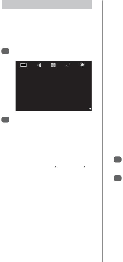
Using the Remote Control
Press the MENU button on the remote control to see the menus.
The menu appears as a list of five topics. As each symbol is selected by pressing zor xon the navigation ring on the remote control, its respective options will appear below.
IMPORTANT: At the bottom of the screen will be a bar displaying a selection of control functions, i.e. Select, Watch, Back, Watch TV.
NOTE: The same menu is displayed in DTV (Digital TV) and ATV (Analogue TV) modes, however, where some items are not available in a mode they will appear greyed out.
To use the options press the fand ebutton on the remote control to move up and down through them and
to select the required choice. Follow the on screen instructions. The functions of each menu are described in detail throughout the manual.
Using the Controls
To alter the volume press — j+.
To alter the programme position press eFf.
Press MENU and S, R, Q or P to control the sound and picture options. Press MENU to finish.
When connecting sound equipment to EXT3, connect the audio output of the equipmentto thephono sockets on the television.
To select the external input, press Band select the required input source. See page 50.
Please always refer to the owner’s manual of the equipment to be connected for full details.
NOTE: Interactive video games that involve shooting a ‘gun’ type of joystick at an on-screen target may not work with this television.
14
Tuning the television for the first time
Before switching on the television put your decoder and media recorder to Standby if they are connected and ensure the aerial is connected. To set up the television use the buttons on the remote control as detailed on page 6.
1 |
Press the ibutton, the Quick Setup screen will |
|
appear. This screen will appear the first time that |
||
|
||
|
the television is switched on and each time Reset |
|
|
TV is selected. |
Quick Setup |
|
|
|
Menu Language |
English |
||
Country |
UK |
|
|
Primary Subtitle Language |
English |
||
Secondary Subtitle Language |
English |
|
|
Primary Audio Language |
English |
||
Secondary Audio Language |
English |
||
|
|
|
|
2 |
Using ehighlight Menu Language, then |
|||||||||
zor xto select. |
|
|
|
|
|
|||||
3 |
Press eto highlight Country and zor xto |
|||||||||
select. The television will now tune the stations for |
||||||||||
|
||||||||||
|
your country. Press OK. |
|
|
|
|
|
||||
4 |
The Location screen will appear, press zor xto |
|||||||||
select between Home or Store (for normal home |
||||||||||
|
||||||||||
|
use select Home) then press OK. |
|||||||||
|
If Home is selected the AutoView option will be |
|||||||||
|
activated, automatically adjusting the picture |
|||||||||
|
setting to the current viewing conditions. In most |
|||||||||
|
cases the television will then operate with lower |
|||||||||
|
energy consumption. |
|
|
|
|
|
||||
5 |
If the Ant/Cable In screen appears, press |
|||||||||
zor xto select between Antenna or Cable |
||||||||||
|
then press OK. |
|
|
|
|
|
||||
6 |
The Auto Tuning start up screen will appear with |
|||||||||
the option to select between DTV and ATV, DTV |
||||||||||
|
or ATV. Using zor xselect DTV and ATV then |
|||||||||
|
press eto highlight Start Scan. |
|||||||||
7 |
Press OK again to start Auto Tuning. The |
|||||||||
television will start to search for all available DTV |
||||||||||
|
||||||||||
|
and ATV stations. The progress bar will indicate |
|||||||||
|
progress. |
|
|
|
|
|
||||
|
You must allow the television to complete |
|||||||||
|
the search. |
|
|
|
|
|
||||
|
|
|
|
|
|
|
|
|
|
|
|
|
Auto Tuning |
|
|
|
|
|
|||
|
|
|
Progress |
|
|
Found |
||||
|
|
DTV Tune |
75% |
|
|
|
|
80 |
|
|
|
|
|
|
|
|
|
||||
|
|
ATV Tune |
|
|
Waiting... |
|
|
|||
|
|
|
|
Channel: C58 |
|
|||||
|
|
|
|
|
|
|
|
|
|
|
When the search is complete the television will automatically select position one.
The Auto Tuning screen will display the total number of services found.
Auto Tuning |
|
|
|
|
||
DTV Services Found: 90 ATV Services Found: 4 |
||||||
|
|
|
|
|
|
|
DTV |
|
|
ATV |
|
|
|
Type |
Pos. |
Name |
CH |
|||
|
|
|
1 |
BBC ONE |
34 |
|
|
|
|
2 |
BBC TWO |
34 |
|
|
|
|
3 |
ITV1 |
31 |
|
|
|
|
4 |
Channel 4 |
31 |
|
|
|
|
5 |
FIVE |
48 |
|
|
|
|
6 |
ITV2 |
31 |
|
|
|
|
7 |
BBC THREE |
34 |
|
8 |
Press zor xto view the DTV (digital channels) |
||||||
or ATV (analogue channels) lists. |
|||||||
|
|||||||
|
|
|
|
|
|
||
|
|
Auto Tuning |
|
|
|
||
|
|
DTV Services Found: 90 |
ATV Services Found: 4 |
||||
|
|
DTV |
ATV |
|
|
|
|
|
|
Pos. |
Name |
|
|
CH |
|
|
|
|
|||||
|
|
|
|
|
|
||
|
|
0 |
VCR |
|
|
C60 |
|
|
|
1 |
BBC ONE |
|
|
C22 |
|
|
|
|
|
|
|
|
|
|
|
2 |
BBC TWO |
|
|
C28 |
|
|
|
|
|
|
|
||
|
|
3 |
ITV |
|
|
C25 |
|
|
|
|
|
|
|
|
|
|
|
4 |
CH4 |
|
|
C32 |
|
|
|
|
|
|
|
|
|
|
|
9 |
Use eor fto move through the list to select a |
|||
channel then press EXIT to view. |
||||
|
||||
|
In ATV mode some areas may receive duplicate |
|||
|
stations. There may not be a clear picture or the |
|||
|
signal may be weak, so the station order can be |
|||
|
changed using ATV Manual Tuning. |
|||
|
NOTE: The time will be set automatically by |
|||
|
transmission but can be advanced or decreased |
|||
|
using Local Time Setting in the DTV Settings |
|||
|
screen. |
|||
|
|
|
||
|
PLEASE NOTE |
|
||
|
The Reset TV menu can also be accessed |
|||
|
at any time from the SETUP menu. |
|||
|
|
|
|
|
15
Setting Antenna or Cable
Ant/Cable In (if available)
If this feature is available the television can be configured to either Antenna or Cable. If the setting is changed the Auto Tuning screen will automatically appear (if a Pin Code has been set this will have to be entered in order to change the setting). All current programmes and settings will be lost.
1 |
Press MENU and use zor xto select SETUP. |
|||||||
Use eto highlight Ant/Cable In. |
||||||||
|
|
|
|
|
|
|
|
|
|
|
|
|
|
|
|
|
|
|
|
|
|
|
|
|
|
|
|
|
|
|
|
|
|
|
|
|
|
|
|
|
|
|
|
|
|
|
SETUP |
|
|
|
|
|
|||||
|
|
Menu Language |
|
English |
|
|||||||
|
|
|
|
|||||||||
|
|
Country |
|
UK |
|
|||||||
|
|
|
|
|||||||||
|
|
Ant/Cable In |
|
Antenna |
|
|||||||
|
|
|
|
|
|
|
|
|||||
|
|
Auto Tuning |
|
|
|
|
|
|||||
|
|
|
|
|
|
|
|
|||||
|
|
ATV Manual Tuning |
|
|
|
|
|
|||||
|
|
|
|
|
|
|
|
|||||
|
|
DTV Manual Tuning |
|
|
|
|
|
|||||
|
|
|
|
|
|
|
|
|||||
|
|
DTV Settings |
|
|
|
|
|
|||||
|
|
|
|
|
|
|
|
|||||
|
|
AV Connection |
|
|
|
|
|
|||||
2 |
Press zor xto select Antenna or Cable. |
|||||||||||
|
|
|
|
|
|
|
|
|
|
|
|
|
|
A screen will appear warning that the televisions |
|||||||||||
|
features will be changed. |
|
|
|
|
|
||||||
|
The Auto Tuning screen will appear. When |
|||||||||||
|
Cable has been selected the Auto Tuning |
|||||||||||
|
screen will show setting options. |
|||||||||||
|
|
|
|
|
|
|
|
|
|
|
|
|
|
|
|
|
Auto Tuning |
|
|
|
|
|
|||
|
|
|
|
|
|
|
|
|
|
|
|
|
|
|
|
|
Tuning Mode |
|
DTV and ATV |
|
|
||||
|
|
|
|
|
|
|
|
|
|
|
|
|
|
|
|
|
|
Start Scan |
|
|
|
|
|
||
|
|
|
|
DTV |
|
|
|
|
|
|||
|
|
|
|
Scan Type |
|
Full Scan |
|
|
||||
|
|
|
|
Start Frequency |
|
Auto |
|
|
||||
|
|
|
|
End Frequency |
|
Auto |
|
|
|
|||
|
|
|
|
Modulation |
|
Auto |
|
|
||||
|
|
|
|
Symbol Rate |
|
Auto |
|
|
||||
|
|
|
|
Network ID |
|
Auto |
|
|
||||
|
|
|
|
|
|
|
|
|
|
|
|
|
With the exception of Scan Type and Modulation, all of the settings have two options:
Auto – values are pre-set by the television’s operating system.
Input – allows a single value to be entered in place of the pre-set value. If no channel is currently tuned and Input is chosen a system default value will be displayed. If a channel is currently tuned and Input is chosen the value of the channel will be displayed.
Scan Type
There are two options, Full Scan and Quick Scan. Quick Scan is a simplified version of Full Scan and takes less time to complete.
Start Frequency
This sets the frequency from which the scan will start.
End Frequency
This sets the frequency at which the scan will stop.
The valid entry range for frequency items is 113.000858.000 for C-Book/Other and 114.000-858.000 for Nordig-C. If numbers outside of this range are entered the values will automatically set to the minimum or maximum valid values.
Modulation
There are five QAM modulation settings to choose from.
Symbol Rate
This is the Baud rate (KS/s) of the scan.
The valid entry range for Symbol Rate is 4000-7200. If a number outside of this range is entered the value will automatically set to the minimum or maximum valid value.
Network ID
This is the Network ID to be used for the scan. This item is greyed out when the Scan Type is set to Full Scan.
The valid entry range for Network ID is 1-65535. If a number outside of this range is entered the value will automatically set to the minimum or maximum
valid value.
3 |
When the options have been set use eor fto |
highlight Tuning Mode, then press zor xto |
|
select between DTV and ATV, DTV or ATV. |
4 |
Press eto highlight Start Scan, then press OK. |
|
16

DTV auto tuning, manual tuning, manual tuning for DVB-C
NOTE: As new services are broadcast it will be necessary to re-tune the television in order to view them.
Auto Tuning
Auto tuning will completely re-tune the television and can be used to up date the channel list.
It is recommended that DTV Auto tuning is run periodically to ensure that new services are added.
All current programmes and settings, i.e. locked programmes, will be lost.
1 |
Press MENU and use zor xto select SETUP. |
|
If available use eto highlight Ant/Cable In and |
||
|
then zor xto select Antenna or Cable. |
|
2 |
Use eto highlight Auto Tuning. Press OK. |
|
|
|
|
|
SETUP |
|
|
Menu Language |
English |
|
Country |
UK |
|
Ant/Cable In |
Antenna |
|
Auto Tuning |
|
ATV Manual Tuning
DTV Manual Tuning
DTV Settings
AV Connection
A screen will appear warning that previous digital channels and settings will be deleted.
Auto Tuning |
|
Previous settings will be lost! Press EXIT for |
|
no change. |
|
Tuning Mode |
DTV and ATV |
Start Scan
3 |
Use zor xto select DTV then press eto select |
|
Start Scan, press OK to start Auto tuning. |
||
|
||
|
The television will start to search for all available |
|
|
DTV stations. |
|
|
You must allow the television to complete |
|
|
the search. |
|
|
When the search is complete the Auto Tuning |
|
|
screen will display the services found. |
|
4 |
Use eor fto move through the list to select a |
|
channel then press OK to view. |
||
|
Manual Tuning
This feature is available for service engineers or can be used for direct channel entry if the multiplex channel is known.
1 |
Select DTV Manual Tuning from the SETUP |
|
menu and press OK. |
2 |
Enter the multiplex number using the number |
buttons or use zor xto adjust the number and |
|
then press eto select Start Scan, press OK. The |
|
television will automatically search for that |
|
multiplex. |
|
When the multiplex is found any channels not |
|
currently on the channel list will be added and |
|
the channel information at the top of the screen |
|
will be updated. |
3 |
Repeat as necessary. Press EXIT to finish. |
|
|
|
|
|
Manual Tuning for DVB-C |
|
|
When Ant/Cable In is set to Cable, DTV Manual Tuning will display the following information:
Frequency – a specific frequency can be input for scanning.
Modulation – select from five QAM modulation options.
Symbol Rate – A specific baud rate (KS/s) can be input for manual scanning.
17
DTV location, auto channel update, DVB character set, Analogue switch off
Location
There are two options available Home and Store. Store is for use when a television is being used for display, i.e. in shops etc. Home is recommended for normal home use.
1 |
Press MENU and use zor xto select SETUP. |
|
Use eto highlight Location. |
|
|
2 |
|
|
|
|
|
|
SETUP |
|
|
Auto Tuning |
|
|
ATV Manual Tuning |
|
|
DTV Manual Tuning |
|
|
DTV Settings |
|
|
AV Connection |
|
|
Picture Position |
|
|
Quick Setup |
|
|
Location |
Home |
3 |
Use zor xto select Home or Store. |
|
|
|
When Home is selected the AutoView option |
|
will be activated, automatically adjusting the |
|
picture setting to the current viewing conditions. |
|
In most cases the television will then operate with |
|
lower energy consumption. |
Auto Channel Update
If Auto Channel Update is set to On when the television is in standby mode Digital Tuning will automatically execute and new channels will be stored.
1 |
Press MENU and use zor xto select SETUP. |
|||||||
Use eto highlight DTV Settings and press OK. |
||||||||
2 |
||||||||
|
|
|
|
|
|
|
||
|
|
|
|
|
|
|
|
|
|
|
DTV Settings |
|
|
||||
|
|
Channels |
|
|
||||
|
|
Channel Options |
|
|
||||
|
|
Subtitle and Audio |
|
|
||||
|
|
PIN Setting |
|
|
||||
|
|
Parental Control |
|
|
||||
|
|
Local Time Setting |
|
11:51 |
|
|||
|
|
Auto Channel Update |
|
On |
|
|||
|
|
DVB Character Set |
|
Standard |
|
|||
3 |
Press eto select Auto Channel Update and |
|||||||
use zor xto select On. |
|
|
||||||
DVB Character Set
The character set to be used for DVB-C or DVT-B channels can be set manually
(Standard – Table 0 or Western – Table 5).
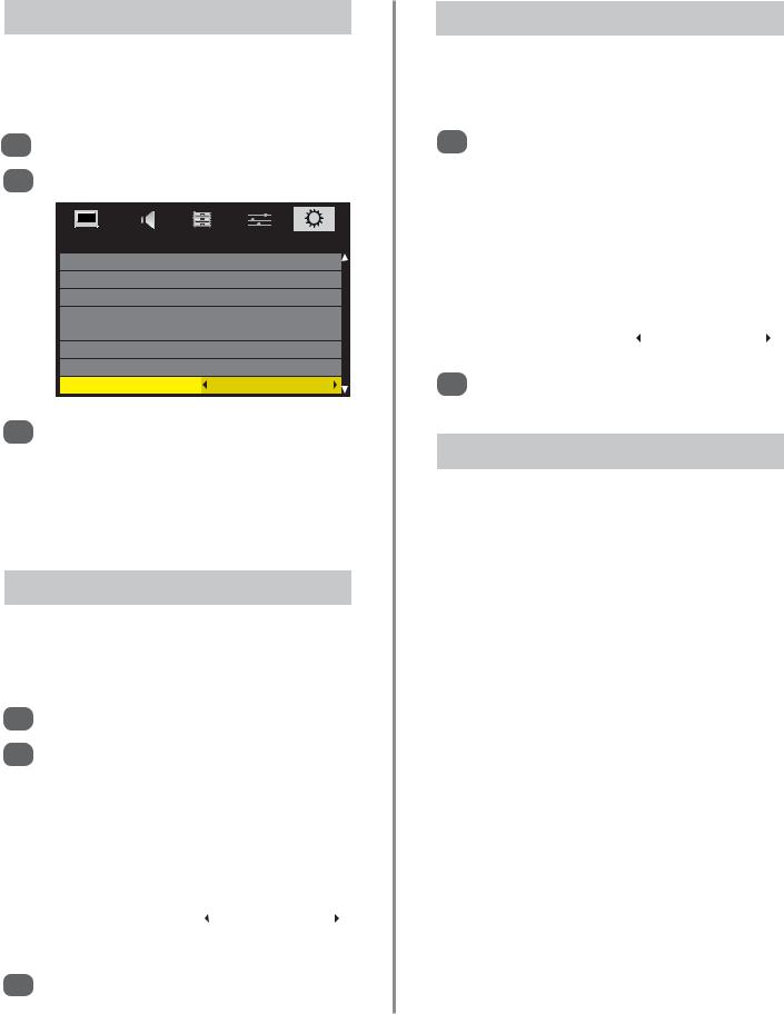
1 |
In the SETUP menu press eto highlight DTV |
|||
Settings and press OK. |
|
|
||
|
|
|
||
|
|
|
|
|
|
DTV Settings |
|
|
|
|
Channels |
|
|
|
|
Channel Options |
|
|
|
|
Subtitle and Audio |
|
|
|
|
PIN Setting |
|
|
|
|
Parental Control |
|
|
|
|
Local Time Setting |
11:51 |
|
|
|
Auto Channel Update |
On |
|
|
|
DVB Character Set |
|
Standard |
|
|
|
|
|
|
2 |
Press eto select DVB Character Set and use |
zor xto select between Standard or West. |
Analogue Switch-off
This is a digital television which is integrated to allow the use of both digital and analogue services. However, during the lifetime of this set it is very likely that analogue services will be switched off to allow for more new digital services.
This ‘switch-off’ will happen in a number of phases, which will be advertised in your area well in advance. It is recommended that at each phase the television is re-tuned to ensure that existing and new digital services can be viewed without disruption.
18
 Loading...