

Page 1
6 F 3 H 1 0 0 1
Uninterruptible Power System (UPS)
TOSNIC-7000S
Instruction Manual (OPERATION)
• This manual should be delivered to the persons who
will ultimately use and maintain the UPS.
• Read this manual carefully before operating the UPS.
REQUIREMENT
• Store the manual in a safe place so it can be referred
to when needed.
July 1999
©
ALL Rights Reserved.
Page 2
6 F 3 H 1 0 0 1
Definitions
(1) Main unit
c UPS: U
* If required by the custom specifications, the unit will be marked as a CVCF device.
CVCF: C
ninterruptible Power System
onstant Voltage Constant Frequency
(2) Main circuit switches
c MCCB: Molded Case Circuit Breaker
d ACB: A
ir Circuit Breaker
(3) Storage cells
c Individual battery system: A parallel UPS system in which there is a battery for each
UPS in the system.
d Shared battery system: A parallel UPS system in which there is a single battery
for all UPS units in the system.
e HS: Vent type stand-alone lead storage battery
f AHH: Sintered electrode type alkaline storage battery
g MSE: Sealed stand-alone lead storage battery
(4) Display
c Graphic display panel: Includes push buttons, display lamps, and the LCD panel
used to display UPS operating procedures and the UPS state.
d LCD: Liquid Crystal Display. This shows the operational
procedure and the status of the UPS unit.
e LED: Light-Emitting Diode. Individual lamps located on the
graphic display panel indicate th e st atus of the UPS unit.
f Scroll buttons: The △ and ▽ buttons are used to scroll th ro ug h the
LCD screens, from the first screen to the last sc reen and then
back to the first screen (or backward from the last screen to the
first screen and then back to the last screen).
(5) Control system
c Synchronized mode: Indicates that the UPS output phase is synchronized with
1. Be sure to read this manual before use and have a good
2. Unauthorized copying of this manual in part or in its entirety is
3. Every effort has been made to ensure that the information in this
either a Dual clock, a bypass, or a free-running clock.
Notices
understanding of the equipment.
Store it nearby where it can be refe rr ed t o when needed.
strictly prohibited.
manual is correct and accurate in all respects. If you note
inconsistencies or omissions, or if you have any qu estions, please
contact the Toshiba Service Center.
© TOSHIBA Corporation 1999
ALL Rights Reserved.
- 1 -
Page 3
1. Introduction
This manual is designed to ensure the safe and correct operation of the TOSNIC-7000S
Uninterruptible Power System (hereafter referred to as "UPS unit"). Please read the "Safety
Precautions" and "Operation" sections of this manual carefully before use and make sure you
have a thorough understanding of the information in these two sections. Keep the manual
handy in a place near the unit so you can refer to it instantly when needed.
Note that this manual was written based on the standard circuits shown in figures 6.2 (page
13). The delivered UPS system may, if desired by the customer, differ from the standard
configuration. Similarly, the displayed markings may differ from those on the standard
system. If this is the case, follow the operating procedures and indications provided in the
development circuit diagrams created individually for the UPS system actually delivered.
Also, while this manual uses the term UPS, the equipment may be marked "CVCF" according
to customer specifications. If this is the case, remember that the term UPS in the manual is
equivalent to CVCF.
2. Safety Precautions
6 F 3 H 1 0 0 1
This manual and the labels on the UPS main unit contain important information designed to
ensure that the UPS unit is used correctly and safely and prevent property loss and injury to
operators and maintenance personnel. Operators and maintenance personnel should follow
all precautions noted in the manual and should have a thorough understanding of the
meaning of the safety signs and safety symbols shown below.
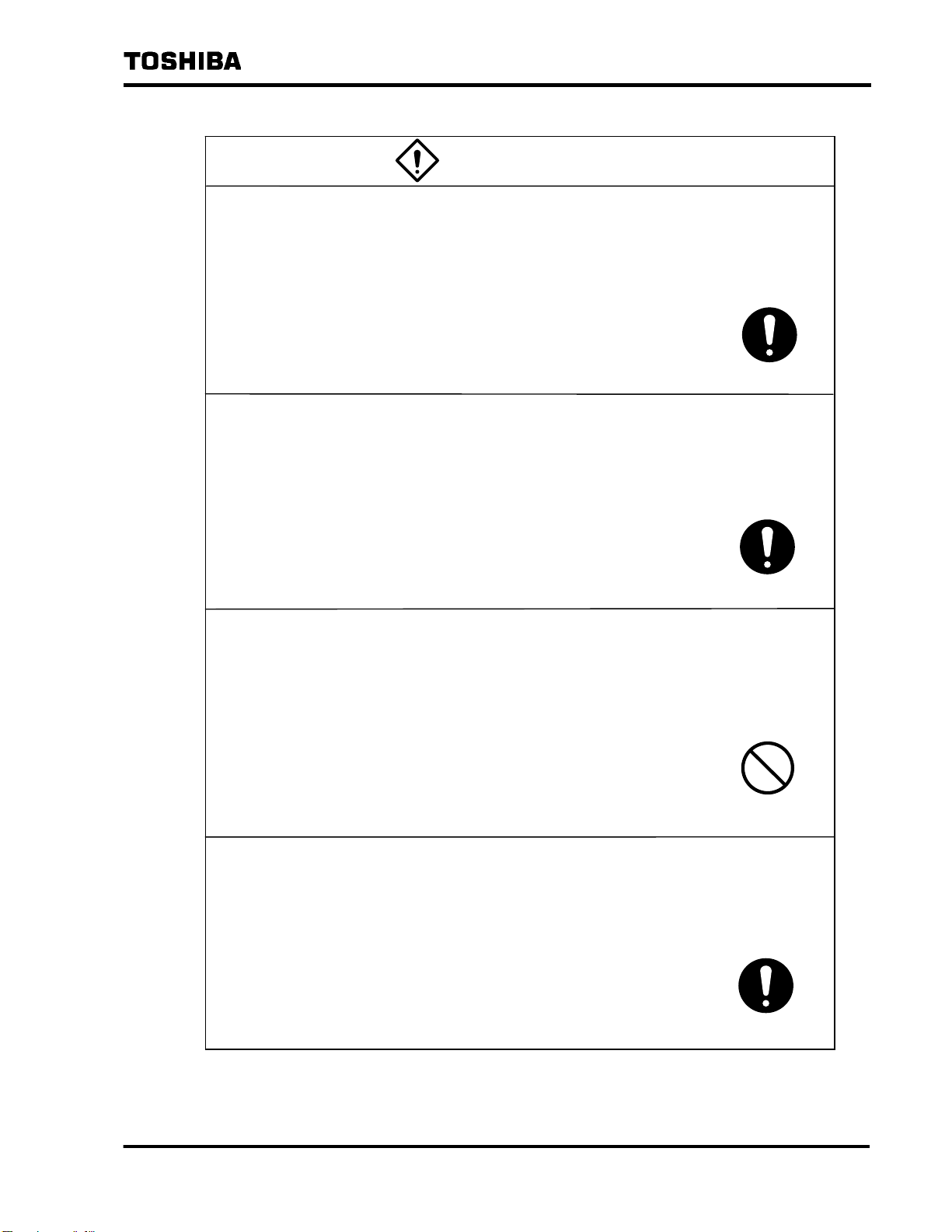
Safety signs
Safety sign Meaning
Indicates that failure to observe proper handling
WARNING
CAUTION
* Here "injury" refers to burns, electrical shock or other injuries that do not
require hospitalization or long-term medical care.
Safety symbols
Safety symbol Meaning
procedures may result in death or serious injury
Indicates that failure to observe proper handling
procedures may result in injury* or property damage
PROHIBITED
The exact nature of what is prohibited is indicated in
pictorial or text form in or near the symbol
MANDATORY
The exact nature of what must be done is indicated in
pictorial or text form near the symbol.
- 2 -
Page 4
2. Safety Precautions (continued)
Use
Special considerations (*) are required when using equipment that affects the
lives and safety of human beings (**) or has a critical effect on maintaining
public services (***). Be sure to contact Toshiba in such cases. The use of such
equipment without special consideration may result in serious accidents.
* Means holding through consultations with system designers regarding
system operation and management and building a backup system for use in
the event of UPS failure.
** • Operating room equipment
• Life support equipment (artificial dialysis, incubators, etc.)
• Noxious gas or smoke eliminators
• Equipment that must be provided under fire laws, construction standards or
other ordinances
• Equipment equivalent to the above
*** • Equipment used to supervise or control airways, railways, roads, sea
lanes or other transportation routes
6 F 3 H 1 0 0 1
• Equipment used to control nuclear power plants, etc.
• Equipment used to control communications
• Equipment equivalent to the above
Warranty
The warranty on this product may not cover all primary, secondary or tertiary
damage resulting from error or failure of this unit, connected units or software.
Checking Warning Labels
Check to make sure that warning labels are displayed in the appropriate places
(see page 6).
If labels are not present or are smudged and therefore illegible, contact the
Toshiba Service Center .
- 3 -
Page 5
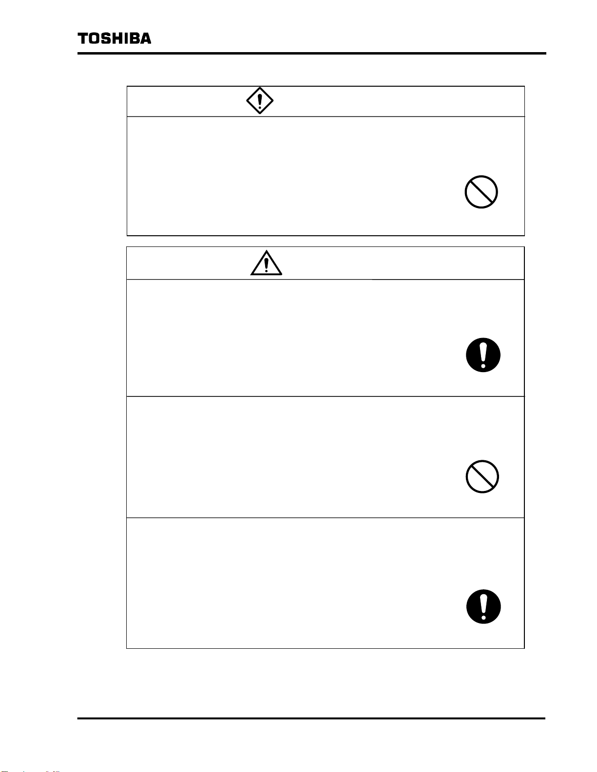
2. Safety Precautions (continued)
If the unit begins to emit smoke or strange odors, immediately turn off circuit
breakers 52R and 72B.
Continued use may result in fire. Contact the Toshiba Service Center.
WARNING
6 F 3 H 1 0 0 1
MANDATORY
Contact the Toshiba Service Center in the event of malfunction or failure.
This unit should be repaired only by authorized Toshiba
service personnel. Servicing by untrained personnel may
increase the scale of the failure or result in electric shock or
injury.
MANDATORY
Do not attempt to modify or move the unit yourself or to have this done by a
third party.
Electric shock, injury or failure may result if persons other
than specially trained Toshiba technicians attempt to modify
or move the unit.
Be sure to contact Toshiba if you wish modifications to be
made or if you wish to move the unit.
PROHIBITED
Only open the front panel when performing necessary operations.*
Operating parts and high-voltage areas inside the UPS have
been provided with covers as a safety precaution. Still,
touching areas other than those that must be touched to
perform necessary operations may result in electric shock,
burns or other injuries.
* In this case, "necessary operations" means
operating circuit breakers/auxiliary
switches and inserting/removing memory
cards
MANDATORY
- 4 -
Page 6
2. Safety Precautions (continued)
Do not open the rear door.
The parts inside carry high voltage. Touching them may
result in electric shock, burns or failure.
WARNING
6 F 3 H 1 0 0 1
PROHIBITED
CAUTION
Operators should be qualified* personnel.
Operation of the UPS by unqualified or untrained personnel
may result in electric shock, injury or failure.
* In accordance with customer stipulations
MANDATORY
Make sure the air vents on the front and top of the unit are not blocked.
Blocking the vents will cause the temperature inside the unit
to rise and may result in fire or unit failure.
PROHIBITED
Make sure you understand the meaning of the warning labels on the equipment,
and follow the precautions indicated.
Operating the equipment with an inadequate understanding
of these matters may result in electric shock or burns.
• See Page 6 for the location of these warning labels.
MANDATORY
- 5 -
Page 7
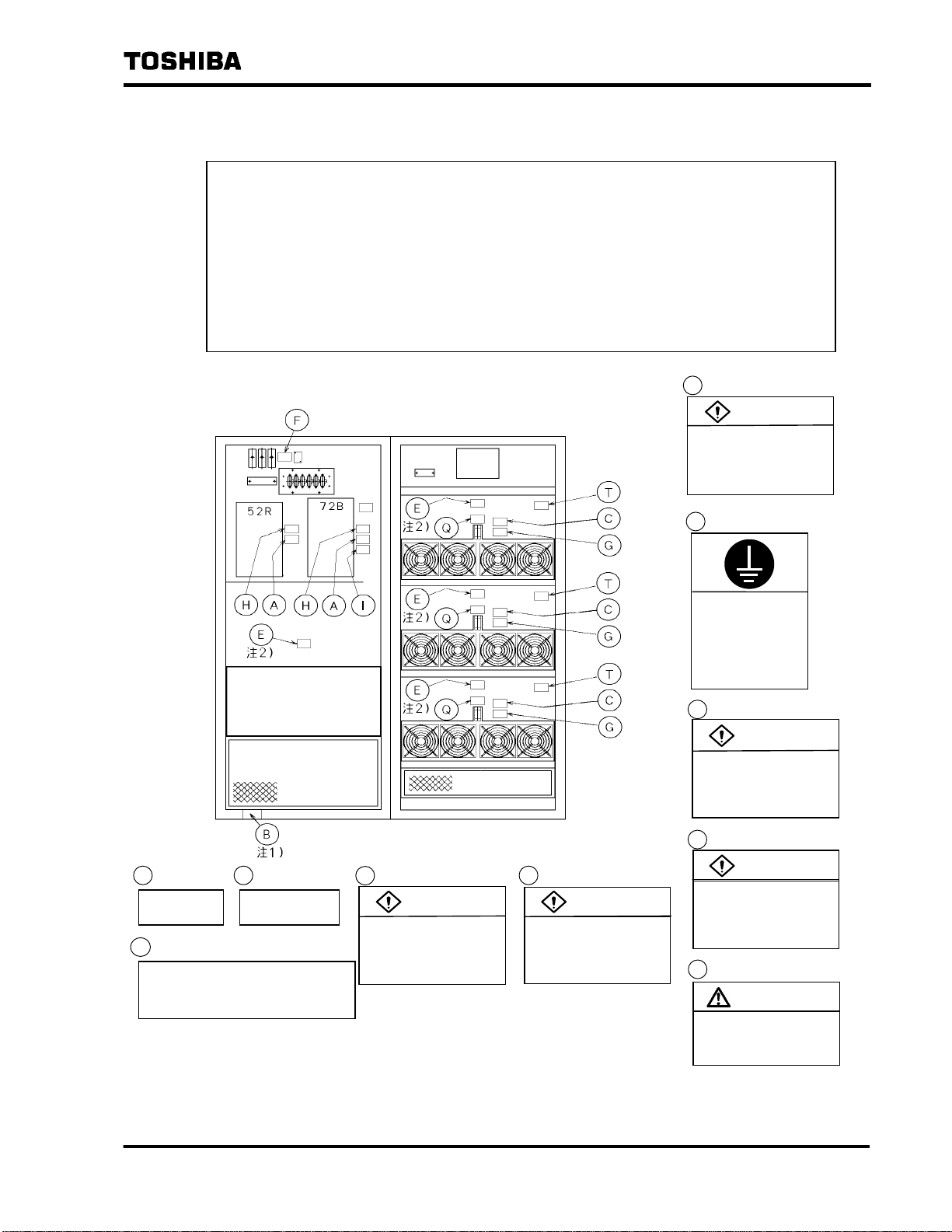
2. Safety Precautions (continued)
Checking warning labels
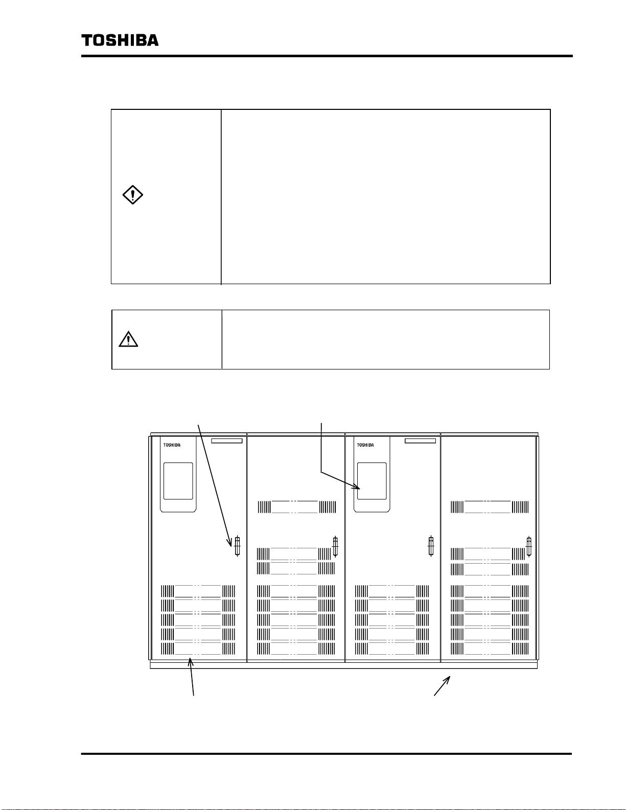
(1) The locations of the warning labels on the UPS are shown in Figure 2.1.
Check to make sure that these warning labels are in place.
Note that the placement and content of the warning labels may differ
depending on the capacity of the UPS. Verify the locations by referring to
the warning label placement figure provided with the "Maintenance &
Inspection 6F3H1002" manual.
(2) Read all warning labels and make sure you understand their meaning.
(3) Make sure warning labels are alw ays legible. Do not allow them to become
smudged and do not remove or cover them up.
Locations of the Warning Labels (Example: 300 kVA)
6 F 3 H 1 0 0 1
A
WARNING
Hazardous voltage
can cause injury or death.
Do not touch primary side
of MCCB.
Q
Be always
turn on
H
Do not turn off
in running
T
Check having fixed completely
G
WARNING
Rotating shaft
can cause injury.
Do not touch
rotating section.
F
Hazardous voltage
can cause injury or death.
Do not touch live part
of orange wiring.
WARNING
with the screw of a unit,
when restoring this unit.
* The nameplate B is attached at the ground wire connection points in each section.
** The nameplates E are mounted in t he v i cinity of the main c i rcuit transfor mers and
reactors that can be seen from the back of the panel.
Figure 2.1 Unit Interior Front (with front panel open) and Warning Labels (Example)
B
Hazardous voltage
can shock.
Connect
grounding terminal
to ground
before operating.
C
WARNING
Hazardous voltage
can cause injury or death.
(Discharge takes
approx. 20 minutes)
D
WARNING
Hazardous voltage
can cause injury or death.
Do not open panel
while operating.
E
CAUTION
Hot surface can burn.
Do not touch transformer
or reactor.
- 6 -
Page 8
3. Handling Precautions
Perform daily and periodic inspections as noted in the maintenance and inspection
plan.
In order to ensure a long service life and optimal performance,
the equipment must be installed in a suitable environment, must
be operated correctly, and must be given the proper daily and
periodic inspections. Maintenance and inspections are
particularly effective in preventing accidents caused by changes
in components that will occur over time. Be sure to have
periodic maintenance work and inspections done by Toshiba
service and maintenance personnel.
For more information on servicing programs and fee options,
contact the Toshiba Service Center.
Operate the unit within the ambient conditions noted in the specifications.
Operating the unit outside these ranges may result in failure.
6 F 3 H 1 0 0 1
During operation, do not turn off the air conditioner for the UPS chamber and the
battery chamber.
This will cause the temperature in these chambers to rise and may result in failure.
PROHIBITED
When starting or stopping the equipment, monitor the operation on the graphic
display panel LCD and follow the procedures described in Chapter 8 "Operation".
Operating the unit in other than the prescribed manner may result in failure.
* The startup and stop procedures presented in this instruction
manual are the operating procedures for independent UPS nits.
For system-wide operating procedures for when other
distribution panels are present, refer to the corresponding
operating procedures manual.
- 7 -
Page 9

3. Handling Precautions (continued)
Do not turn the circuit breakers ON when control power source switch (8A) is OFF.
This may result in failure.
Certain units also have a control power source switch (8D).
This switch has the same functions as the switch 8A.
6 F 3 H 1 0 0 1
PROHIBITED
Do not turn the control power source switch (8A) to the OFF position when the
circuit breakers are ON.
This may result in failure.
Certain units also have a control power source switch (8D).
This switch has the same functions as the switch 8A.
PROHIBITED
When operating the keys on the graphic display panel, hold down the key for at
least 0.5 second.
The operation may not be performed if the key is held down for
shorter periods of time.
When operating the reset key on the graphic display panel, hold down the key for at
least 5 seconds.
The reset operation may not be performed if the key is held
down for shorter periods of time.
- 8 -
Page 10
3. Handling Precautions (continued)
When the unit has stopped due to failure, be sure to remove the memory card
before resetting the LCD Failure Error screen on the panel.
Resetting (restarting) the UPS without removing the memory card will
delete the data needed to determine the cause of the failure.
Do not leave the unit for long periods of time (1 week) with control power source
switch (8A) in the OFF position.
This can cause the backup capacitor on the control board to become
discharged and result in incorrect time display and other problems.
6 F 3 H 1 0 0 1
PROHIBITED
- 9 -
Page 11

4. Contents
1. Introduction····························································································································2
2. Safety Precautions·················································································································2
3. Handling Precautions ············································································································7
4. Contents································································································································10
5. Appearance···························································································································11
6. Controls and Circuit Configuration·····················································································12
6.1 Panel Controls·················································· ··········································· ····················12
6.2 Circuit Configuration········································································································13
6.3 Panel Controls·················································· ··········································· ····················14
6.3.1 Panel Key-switch·································································································15
6.3.2 Panel Keys ··········································································································15
7. Panels····································································································································17
7.1 Graphic Display Panel·····································································································17
7.2 LCD Display····························································································· ························20
7.2.1 Normal Display Screen························································································21
7.2.2 Failure Display Screen························································································23
7.2.3 Warning Data Display Screen·············································································23
7.2.4 LCD Screen Switching ························································································24
8. Operation······························································································································25
8.1 Types of Operation··········································································································26
8.2 Pre-operational check ······ ·······························································································26
8.3 Procedures ·························································· ············································ ················27
8.3.1 Startup ················································································································27
8.3.2 Switch Power Supply (UPS → Bypass)····························································31
8.3.3 Stop ·····················································································································32
8.3.4 Complete Shutdown····························································································34
8.3.5 Changing Between Floating Charge and Equalized Charge
(For HS or AHH individual battery systems) ·····················································36
8.3.6 Changing to Floating Charge etc. (for MSE individual battery)··························38
8.3.7 Changing the Power Supply to Maintenance Bypass.·······································39
9. Troubleshooting···················································································································40
9.1 Types of Errors································································································ ················42
9.2 LCD Failure Displays·······································································································43
9.2.1 Failure Data Screen ····························································································43
9.2.2 Warning Data Screen··························································································44
9.2.3 Failure Messages································································································45
9.2.4 Scrolling Through LCD Screens in the Event of Failure ·····································48
9.3 Saving Waveforms ··········································································································50
9.4 Restoring UPS Operation········································ ························································50
6 F 3 H 1 0 0 1
- 10 -
Page 12
p
5. Appearance
Only open the front panel when performing necessary
operations.*
Operating parts and high-voltage areas inside the UPS have
been provided with covers as a safety precaution. Still, touching
areas other than those that must be touched to perform
necessary operations may result in electric shock, burns or other
WARNIN
injuries.
6 F 3 H 1 0 0 1
G
CAUTION
* In this case, "necessary operations" means operating circuit
breakers/auxiliary switches (6CH/8A) and inserting/removing
memory cards
Do not open the rear door.
The parts inside carry high voltage. Touching them may result in
electric shock, burns or failure.
Make sure the air vents on the front and top of the unit are not
blocked.
Blocking the vents will cause the temperature inside the unit to
rise and may result in fire or unit failure.
Example: 300 kVA
Front panel handle (includes a lock)
Graphics display panel
Channel baseFront air vent
Figure 5.1 Unit Exterior (front)
* This is an example of the appearance of a standard configuration unit (300 kVA) UPS.
In some cases, de
ending on system configuration, an additional panel may be
- 11 -
Page 13
6 F 3 H 1 0 0 1
6. Controls and Circuit Configuration
If the unit begins to emit smoke or strange odors, immediately
WARNIN
G
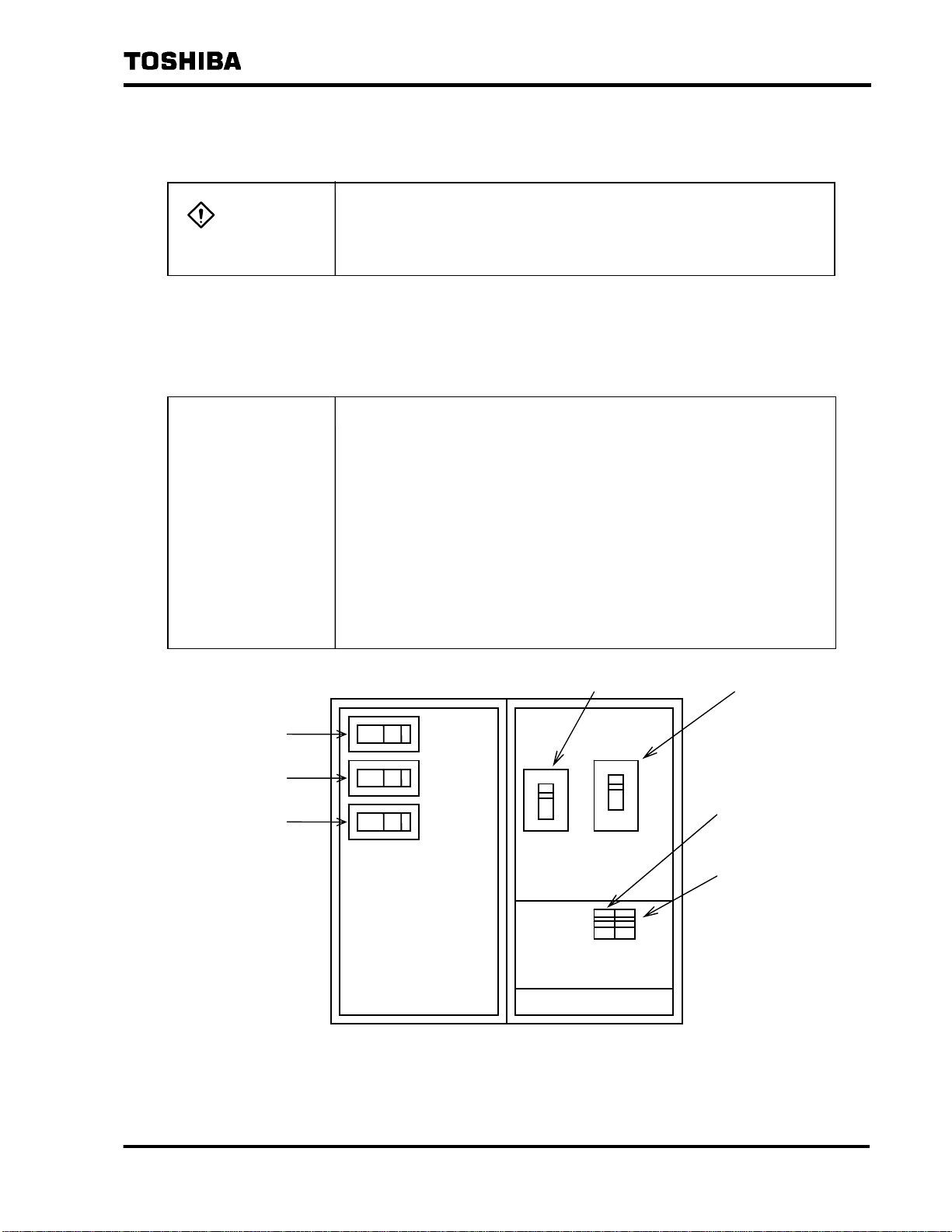
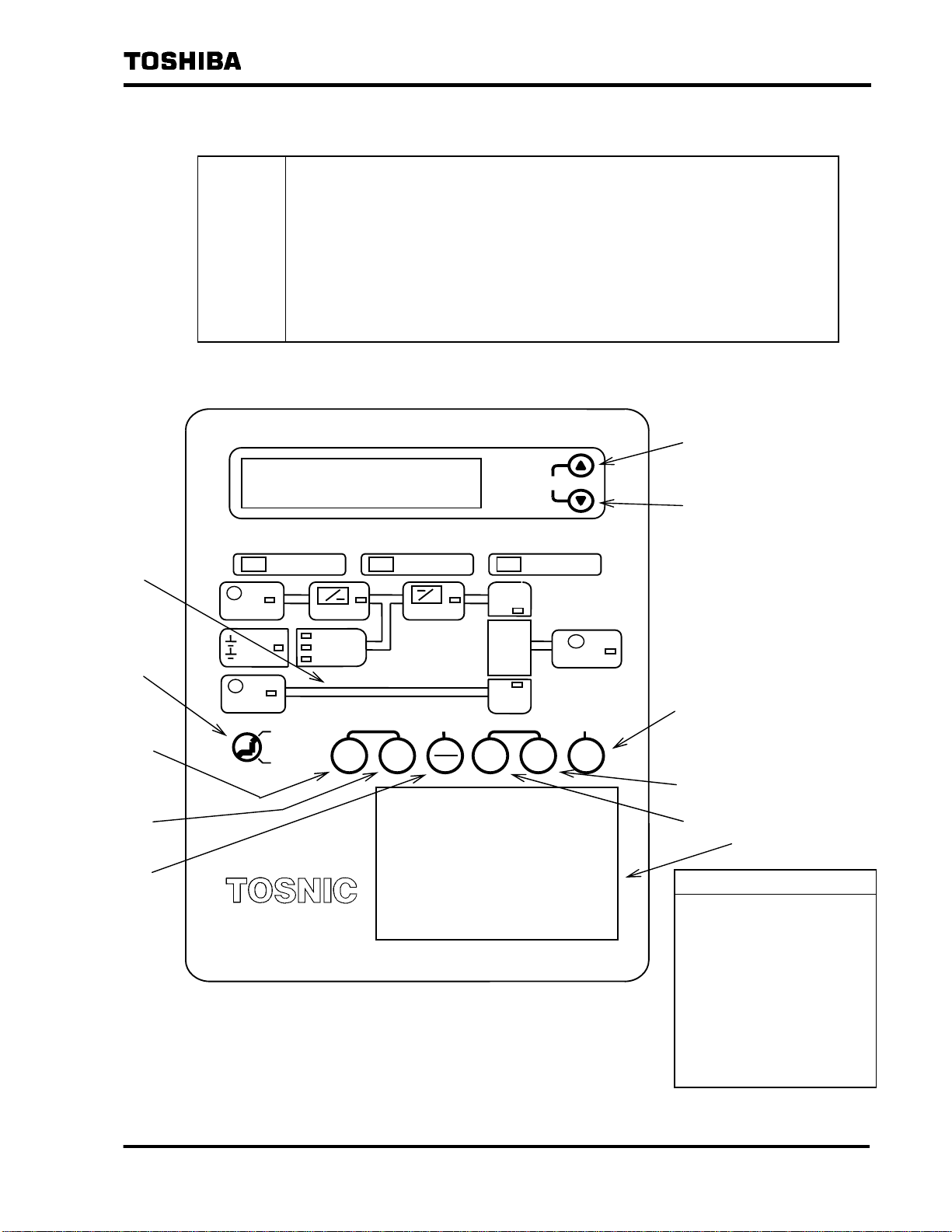
6.1 Panel Controls
Figure 6.1 and Table 6.1 show the locations and functions of the controls used for the circuit
configurations (see Figures 6.2) on the UPS.
NOTES
turn off circuit breakers 52R and 72B.
Continued use may result in fire. Contact the Toshiba Service
Center .
Do not turn the circuit breakers ON when control power source
switch (8A) is OFF.
This may result in failure.
Do not turn the control power source switch (8A) to the OFF
position when the circuit breakers are ON.
This may result in failure.
* Certain systems are also provided with a control power source
switch (8D).
This switch has the same functions as the switch 8A.
Example: 300 kVA
e52R
f52M
g52L
The figure above is only an example; the layout may be
different depending on capacity and system configu ration.
If an MCCB with auxiliary handles is used as the circuit
breaker, use the auxiliary handles during operation.
c52R
d72B
h8A
i6CH
Figure 6.1 Location of Control (in panel)
- 12 -
Page 14
6 F 3 H 1 0 0 1
Table 6.1 Control Functions
No. Device Name / Function Normal Status
c
Main circuit AC input circuit breaker
52R
When the AC input is normal, power is
During Operation
ON
supplied to the UPS through this circuit
breaker.
d
Main circui t DC input circuit breaker
72B
When AC input has been cut off, power is
ON
supplied from the battery to the UPS
through this circuit breaker.
e
Bypass AC circuit breaker
52C
When bypass power is supplied, power is
ON
supplied to the load through this circuit
breaker.
f
Maintenance bypass AC circuit breaker
52M
When bypass power is supplied for UPS
OFF
maintenance, power is supplied to the
load through this c i r c u it breaker.
g
AC output circuit breaker
52L
While UPS power or bypass power is
ON
supplied, power is supplied to the load
through this circuit breaker.
h
Control power source switch
8A
When AC input is normal, pressing this
ON
switch supplies power to the control power
source.
i
Precharge circuit button
6CH
Pressing this button supplies power to t h e
ON
circuit that precharges the DC electrolyt ic
capacitor before power is supplied to
circuit breaker 52R.
Remarks
When the circui t br ea k e r
is tripped in manual
mode, reset it by grasping
the handle and pulling it
down or to the right.
Certain systems are
also provided with the
switch 8D.
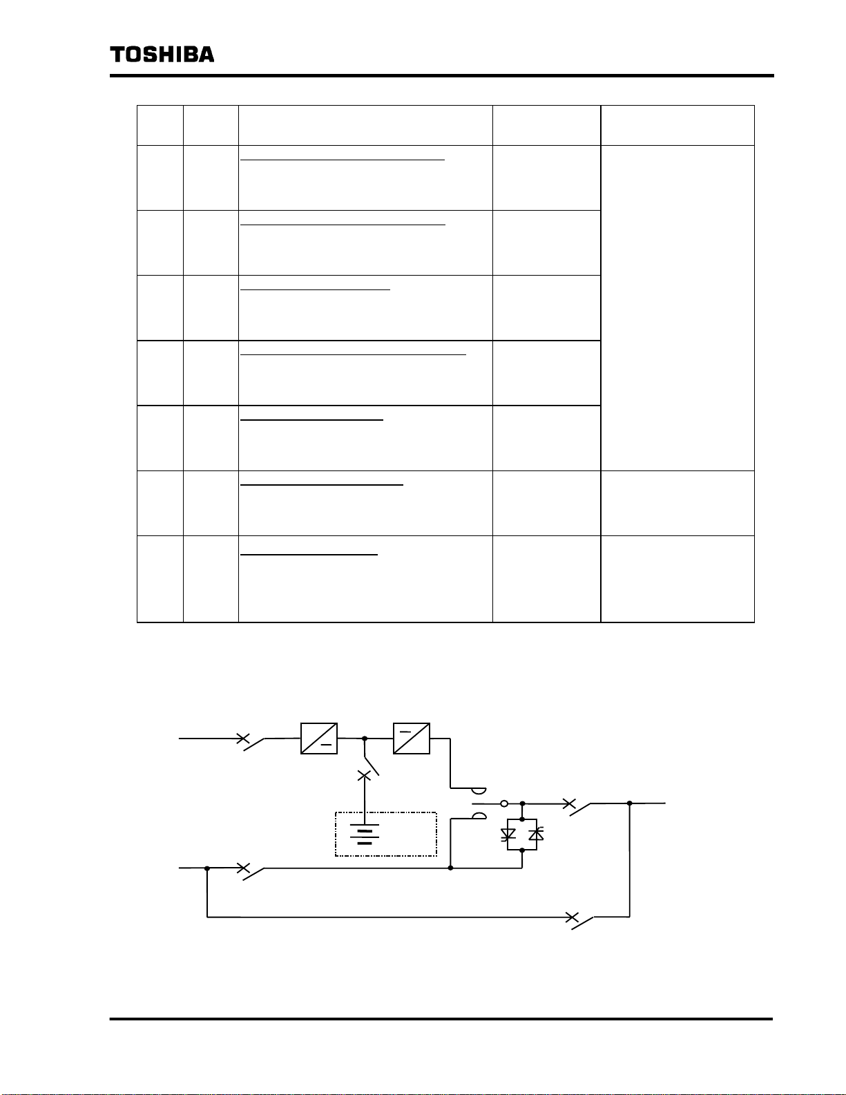
6.2 Circuit Configuration
UPS
AC INPUT
BYPASS
AC INPUT
52R
52C
~
Figure 6.2 Standard Circuit Configuration
~
72B
52L
AC OUTPUT
BATTERY
52M
- 13 -
Page 15
AC S
6.3 Panel Controls
When the unit has stopped due to failure, be sure to remove the
memory card before resetting the LCD Failure Error screen on the
panel, so you can give it to the service person.
Resetting (restarting) the UPS without removing the memory card will
NOTES
The locations of the controls on the panel are shown in Figure 6.3.1. For the functions of
each of the controls, see Section 6.3.1 "Panel Key-switch" and Section 6.3.2 "Panel Keys."
delete the data needed to determine the cause of the failure.
Every effort has been made to ensure safety in unit handling.
However, when removing the memory card, do not touch the other
sections of the unit.
Touching the other sections of the unit may result in electric shock.
6 F 3 H 1 0 0 1
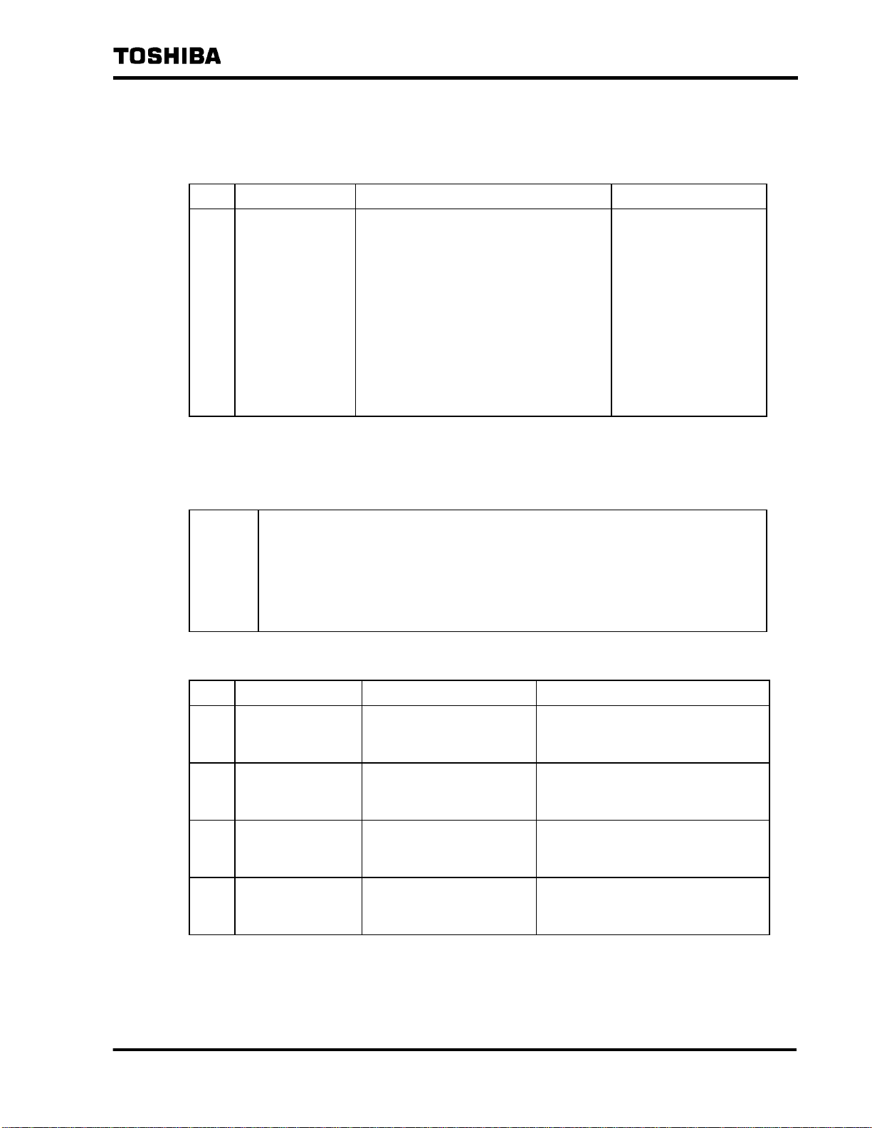
i
SCROLL
(**)
c
e
d
h(*)
j
UPS SUPPLY
~
AC INPUT
BATTERIES
~
BYPASS INPUT
OPERATION
FLOAT CHARGE
EQUAL CHARGE
DISCHARGE
OPERATION
INHIBITED
WARNING FAULT
~
CONVERTER
UPS
STOP
RUN
~
INVERTER
CHARGE
EQUAL
FLOAT
BYPASS
UPS
AC
SWITCH
BYPASS
WITCH FAULT
UPS
~
AC OUTPUT
RESET
k
g
f
NOTE ***
Figure 6.3.1 Panel Controls
(For individual battery systems. For HS or AHH batteries.)
* This will be the "FLOAT" key for MSE individua l ba ttery systems.
** This will be the "PROTECTION" LED for MSE individual battery
systems.
l(***)
Do not use the keypad on
graphic display panel l.
This keypad is used to
change the internal
settings and should
only be used by
maintenance
personnel.
It is not used during
normal operation.
- 14 -
Page 16
6.3.1 Panel Key-switch
Table 6.2 shows the function of the key-switch on the graphic display panel.
No. Name Function Remarks
6 F 3 H 1 0 0 1
Table 6.2 Key-switch Function
c
OPERATION
LOCK
Setting this key-switch to the "OPERATION"
side enables operation using the buttons on
the panel; setting it to the "OPERATION
INHIBITED" side prevents operation. When
the switch is set to the "OPERATION
INHIBITED" side, buttons d - h and k in
Table 6.3 are inoperative and pressing them
has no effect upon the operation of the UPS.
LCD scroll buttons i and j are effective
regardless of the position of this switch.
6.3.2 Panel Keys
Table 6.3 shows the functions of the keys on the graphic display panel.
NOTES
When operating the keys on the graphic display panel, hold down the key for
at least 0.5 second.
When operating the reset key on the graphic display panel, hold down the
key for at least 5 seconds.
The operation may not be performed if the key is held down for shorter periods
of time.
Normally setting the
switch to the
OPERATION INHIBITED"
prevents operational
errors. The key can be
removed when it is set to
the "OPERATION
INHIBITED" position; it
cannot be removed when
the switch is set to the
"OPERATION" position.
Table 6.3 Key Functions (For HS or AHH individual battery systems)
No. Name Function Remarks
RUN Starts up the UPS. The UPS starts up when this key is
d
pressed after the required operational
preparations are complete.
STOP Stops the UPS. Pressing this key during operation
e
prepares the UPS to be stopped with
the required procedure.*
UPS Changes to UPS power
f
supply
BYPASS Changes to bypass power
g
supply
Pressing this key during UPS operation
when bypass power is being supplied
changes it to UPS power.
Pressing this key during UPS operation
when the bypass is normal changes it to
bypass power.
- 15 -
Page 17

6 F 3 H 1 0 0 1
Table 6.3 Key Functions (For HS or AHH individual battery systems) (continued)
No. Name Function Remarks
FLOAT / EQUAL**
h
***
i
SCROLL UP
j
SCROLL DOWN
k
RESET Resets the Failure Data
,
Changes the battery charging
mode.
These keys switch the screen
displayed on the LCD.
screen and Warning Data
screen shown on the LCD.
Pressing this key during UPS operation
changes the status to equalized charge
(If it is currently set to floating charge) or
floating charge (If it is currently set
equalized charge).
For details, see Section 9.2.4 "Scrolling
Through LCD Screens in the Event of
Failure" on Page 47, and Section 7.2.4
"Changing the LCD Screen switching"
on page 24.
* Pressing this key when a power outage has occurred (du rin g DC op eration), causing a
trip error and stopping the UPS. For spe cial systems in which a separate DC UPS is
connected to this unit for use as a control pow er so urce , the unit stops normally.
** In an MSE individual battery system, the FLO AT switch switches the battery charge mode
from protected to floating.
*** This switch is not present in shared battery systems.
- 16 -
Page 18

7. Panels
7.1 Graphic Display Panel
Figure 7.1.1 and 7.1.2 and Table 7.1 show the locations and functions of the controls on the
graphic display panel.
11
6 F 3 H 1 0 0 1
(*)
12
16
15
20
21
19
23
22
~
AC INPUT
BATTERIES
~
BYPASS INPUT
UPS SUPPLY
~
CONVERTER
FLOAT CHARGE
EQUAL CHARGE
DISCHARGE
OPERATION
OPERATION
INHIBITED
WARNING FAULT
STOP
UPS
~
INVERTER
CHARGEAC SWITCH FAULT
RUN
EQUAL
FLOAT
SWITCH
BYPASS
BYPASS
UPS
AC
SCROLL
UPS
~
AC OUTPUT
RESET
13
14
17
24
18
25
(**)
* This will be the "PROTECTION" LED for MSE individual battery systems.
** This will be the "FLOAT" key for MSE individual battery systems.
Figure 7.1.1 Graphic Display Panel Controls (For HS or AHH battery)
- 17 -
Page 19

A
6 F 3 H 1 0 0 1
11
12
16
15
20
19
23
22
~
AC INPUT
BATTERIES
~
BYPASS INPUT
UPS SUPPLY
~
CONVERTER
FLOAT CHARGE
DISCHARGE
OPERATION
OPERATION
INHIBITED
WARNING FAULT
STOP
UPS
RUN
~
INVERTER
UPS
AC
SWITCH
BYPASS
C SWITCH FAULT
BYPASS
SCROLL
UPS
~
AC OUTPUT
RESET
13
14
17
24
18
25
Figure 7.1.2 Graphic Display Panel Control
(Graphic Display Panel of the type without the equalized
charge mode and the protection charge mode).
- 18 -
Page 20

6 F 3 H 1 0 0 1
Table 7.1 Display Panel Functions (For HS or AHH individual battery systems)
No. Name Function
11
LCD INDICATOR Displays help messages, measurement data and
warning descriptions. For more informatio n, see Section
7.2 "LCD Display."
12
UPS SUPPLY LED This LED lights up when the UPS is oper ating.
13
WARNING LED This LED blinks in the event of an warning.
14
FAULT LED This LED lights up in the event of a UPS failure.
15
AC INPUT LED This LED lights up when the AC input circuit breaker
(52R) has gone ON.
16
CONVERTER LED This LED is unlit when the converter has stoppe d
operating. It blinks when the converter is starting up
and is lit when startup is complete.
17
INVERTER LED This LED is unlit when the inverter has stoppe d
operating. It blinks while the inverter is starting up and is
lit when startup is complete.
18
AC OUTPUT LED This LED lights up when the AC output circuit breaker
(52L) is ON and AC voltage has been established.
19
BATTERIES LED This LED lights up when the main circuit DC input circuit
breaker (72B) has goes ON.
20
FLOATING CHARGE
LED**
21
EQUAL CHARGE LED*, ** This LED lights up when the charging mode is set to
This LED lights up when the charging mode is set to
floating charge.
equalized charge.
22
DISCHARGE LED This LED lights up when the battery is being discharged.
23
BYPASS INPUT LED This LED lights up when the bypass input circuit breaker
(52C) has gone ON.
24
UPS LED This LED lights up when the selector switch is set to the
UPS side.
25
BYPASS LED This LED lights up when the selector switch is set to the
bypass side.
* This becomes the PROTECTION LED in MSE indi v i du al b at tery systems.
** This switch is not present in shared battery systems.
- 19 -
Page 21

7.2 LCD Display
The LCD Display screens consist of the following screens.
(1) Normal Display screen ............. Initial display, operation guidance, and measurement
(2) Failure Data Display screen..... Displays detailed data when a failure occurs.
(3) Warning Data Display screen... Displays detailed data when a warning occurs.
The operator can switch between these screens by pressing the scroll keys.
6 F 3 H 1 0 0 1
value display
: Scroll up
: Scroll down
Normal Display screen
Failure Data
Display screen
Warning Data
Display screen
- 20 -
Page 22

7.2.1 Normal Display Screen
The Normal Display screen indicates the operational status of the UPS and provides a total of
nine screens: one Operation Guidance Display screen and eight Measurement Value Display
screens.
Table 7.2 presents examples of these screens.
No. LCD Screen Description
6 F 3 H 1 0 0 1
Table 7.2 Normal Display Screen
1 Help screen
(Example 1) Operation status
OPERATION GUIDANCE
MOVE #52R TO “ON” POSITION
Shows the status of the UPS at the top and help
messages or measurements underneath.
(Example 1)Shows help messages when start ing
or stopping operation.
(Example 2) (Example 2)Shows the output voltage and output
UPS SUPPLY
AC-VO 200[V]
AC-
I O 50[%]
current during operation.
Voltage (example)
Current ratio (example)
2 Measurement screen
(Example) Output voltage
O/P VOLTAGE (LINE)
U - V 200[V]
Shows the output voltage betwee n lin es.
V - W 200[V]
W
- U 200[V]
3 Measurement screen
(Example)
value)
O/P CURRENT (r.m.s)
Output current (RMS
U 50[%]
V
W 50[%]
50[%]
Shows the RMS value for the output current for
each phase as a proportion (%) of the rated
value.
4 Measurement screen
(Example) Output current (peak)
O/P CURRENT (PEAK)
U 50[%]
V
W 50[%]
50[%]
Shows the peak value for the output current for
each phase as a proportion (%) of the rated
value.
Peak value for actual output curr en t
TMRS value for rated current × 1.41
- 21 -
× 100 [%]
Page 23

Table 7.2 Normal Display Screen (continued)
6 F 3 H 1 0 0 1
5 Measurement screen
(Example) Output frequency
O/P FREQUENCY
FREQ. 60.0[Hz]
6 Measurement screen
(Example) AC input
AC INPUT
AC I/P-V 200[V]
FREQ. 60.0[Hz]
7 Measurement screen
(Example) Bypass input
BYPASS INPUT
BYP I/P-V 200[V]
FREQ. 60.0[Hz]
8 Measurement screen
(Example) DC value
DC INPUT
DC-V 401[V]
BATT-V
BATT-
401[V]
I 0[A]
9 Measurement screen
(Example) Counter value
MODE COUNT
UPS 17544[H]
BATTERY
32[MIN]
0[TIM]
Shows the output frequency.
Shows the frequency and voltage values for AC
input.
Shows the frequency and voltage values for
bypass input.
Shows the DC voltage and DC current .
For the current value, "-" indicates cha rging and
the absence of a plus/minus sign indicate s
discharging.
Shows the total time of UPS op er ation and the
number of times the battery has been operated
and total time for battery use (the time AC input
has been off).
- 22 -
Page 24

7.2.2 Failure Display Screen
The Failure Display screen indicates the presence or absence of failure data and displays
that data if present.
LCD Screen Description
6 F 3 H 1 0 0 1
Table 7.3 Failure Display Screen
Presence or absence of failure data
FAULT
Failure data
FAULT
1 52R TRIP
98-09-09 08:05:30
↓ANOTHER ITEM
NO FAULT INFORMATION
* If there is failure data, that data will remain in the system, even after the actual cause of the
failure has been resolved, until the fa ilu re di sp lay reset key on the front of the panel is
pressed and held down for at least 5 seconds. Note that the failure data is not deleted when
the unit is turned off.
This screen indicates the presence or absence of
failure data.
This screen is displayed if there is no failure data,
or if all failure data has been reset with the "fault
display rest" key.
The failure data, the time the failure occurred, and
an indication as to whether or not there is any
other failure data is displayed with this screen if a
failure occurs.
When there is other failure data, that other data
can be displayed using the △ ▽ scroll keys.
7.2.3 Warning Data Display Screen
The Warning Data Display screen indicates the presence or absence of warning data and
displays that data if present.
Table 7.4 Warning Data Display Screen
LCD Screen Description
Presence or absence of warning data
WARNING
NO ALARM INFORMATION
Warning date
WARNING
1 72B MIS OPE
98-09-09 08:05:30
↓ANOTHER ITEM
This screen indicates the presence or absence of
warning data.
This screen is displayed if there is no warning
data, or if all warning data has been reset with the
"fault display reset" key.
The warning data, the time the warning occurred,
and an indication as to whether or not th ere is any
other warning data is displayed with this screen if
a warning occurs.
When there is other warning data, tha t other data
can be displayed using the △ ▽ scroll keys.
- 23 -
Page 25

7.2.4 LCD Screen Switching
The △ and ▽ scroll buttons on the front of the panel are used to switch the screen
displayed on the LCD.
See figure 6.3.1 for the location of the △ and ▽ scroll buttons.
Symbol Name Description
SCROLL
▲
UP
6 F 3 H 1 0 0 1
Moves to the previous screen
(see Figure 7.2)
SCROLL
▼
DOWN
Moves to the next screen
(see Figure 7.2)
Initial screen
UPS SUPPLY
AC-VO 200[V]
AC-
<Normal screen>
I O 50[%]
WARNING
NO ALARM INFORMATION
O/P VOLTAGE (LINE)
U - V 200[V]
V - W 200[V]
W
- U 200[V]
O/P CURRENT (r.m.s)
U 50[%]
V
W 50[%]
50[%]
FAULT
NO FAULT INFORMATION
MODE COUNT
UPS 17544[H]
BATTERY
32[MIN]
0[ TIM]
O/P CURRENT (PEAK)
U 50[%]
V
W 50[%]
50[%]
O/P FREQUENCY
FREQ. 60.0[Hz]
AC INPUT
AC I/P-V 200[V]
FREQ. 60.0[Hz]
Figure 7.2 Using the Scroll Keys
DC INPUT
DC-V 401[V]
BATT-V
BATT-
401[V]
I 0[A]
BYPASS INPUT
BYP I/P-V 200[V]
FREQ.
60.0[Hz]
- 24 -
Page 26

8. Operation
CAUTION
This section will describe the basic procedures used to operate the UPS.
6 F 3 H 1 0 0 1
Operators should be qualified* personnel.
Operation of the UPS by unqualified or untrained personnel may
result in electric shock, injury or failure.
* In accordance with customer stipulations
Make sure you understand the meaning of the warning labels
on the equipment, and follow the precautions indicated.
Operating the equipment with an inadequate understanding of
these matters may result in electric shock or burns.
See Page 6 for the location of these warning labels.
Operate the unit within the ambient conditions noted in the
specifications.
Operating the unit outside these ranges may result in failure.
NOTES
During operation, do not turn off the air conditioner for the UPS
chamber and the battery chamber.
This will cause the temperature in these chambers to rise and
may result in failure.
When starting or stopping the equipment, monitor the
operation on the graphic display panel LCD and follow the
procedures.
Do not leave the unit for long periods of time (1 week) with
control power source switch (8A) in the OFF position.
This can cause the backup capacitor on the control board to
become discharged and result in incorrect time display and other
problems.
- 25 -
Page 27

8.1 Types of Operation
This section summarizes the types of operations covered in this manual and their objectives.
Refer to the attached operating procedures document for specific details on the operating
procedures.
No. Operation General Description/Objective Page No.
1 Startup Starts up and operates the stopped UPS. Page 27
6 F 3 H 1 0 0 1
2 Switch Power Supply Switches between UPS powe r supply and
3 Stop Stops a UPS that is operating. Page 32
4 Complete shutdown Turns off the control power supply and shuts
5 Charge
(floating/equalized)
6 Floating charge Used to change the charging mode manually
7 Supply power to
maintenance
bypass
8.2 Pre-operational check
Be sure to check the following items before operating the UPS:
(1) Make sure all internal covers are in place.
(2) Make sure all doors are closed. If doors are opened to operate circuit breakers, switches
and the like, be sure to close them afterward.
bypass power supply.
down the UPS completely.
Changes the mode for battery charging (in the
case of HS or AHH individual battery).
from protective charge to floating charge (in
the case of an MSE individual bat tery).
Changes the supply of power to the load to
bypass power supply (when the UPS must be
shut down completely for maintenance,
inspection, etc.).
Page.31
Page 34
Page 36
Page 39
Page 39
(3) Make sure the air conditioners in the UPS chamber and battery chamber are operating.
(4) When starting up the UPS, make sure all circuit breakers (52R,72B,52C,52L and 52M)
and switches (8A and 6CH) are off. (Certain systems are also provided with the switch
8D.)
(5) When starting up the UPS, check on the equipment supplying power to the UPS to make
sure AC input voltage is being supplied to the UPS.
- 26 -
Page 28

8.3 Procedures
8.3.1 Startup
Table 8.1 shows the procedure used to start up the UPS.
LED status : Unlit : Lit : Blinking
Step Procedure LCD/LED Status (After Execution)
6 F 3 H 1 0 0 1
Table 8.1 Startup Procedures
1 Turn on the control
power supply switch
(8A) on the panel.
2 Turn on the bypass AC
input 52C and the AC
output 52L circuit
breakers.
(The UPS will change
to bypass power
supply status and AC
output voltage will be
generated.)
AC INPUT
BYPASS INPUT
AC INPUT
BYPASS INPUT
~
BATTERIES
~
~
BATTERIES
~
OPERATION GUIDANCE
MOVE #52C AND #52L TO ‘ON’ POSITION
~
CONVERTER
FLOAT CHAR GE
EQUAL CHARGE
DISCHARGE
INVERTER
~
UPS
AC
SWITCH
BYPASS
The "BYPASS" LED lit.
BYPASS
MOVE #6CH TO ‘ON’ POSITION
~
CONVERTER
FLOAT CHAR GE
EQUAL CHARGE
DISCHARGE
INVERTER
~
UPS
AC
SWITCH
BYPASS
~
AC OUTPUT
~
AC OUTPUT
The "BYPASS INPUT" and The "OUTPUT"LEDs lit.
Turn on the precharge
3
circuit switch (6CH)*.
BYPASS
WAIT FOR A WHILE
~
AC INPUT
BATTERIES
~
BYPASS INPUT
~
CONVERTER
FLOAT CHAR GE
EQUAL CHARGE
DISCHARGE
INVERTER
~
UPS
AC
SWITCH
BYPASS
~
AC OUTPUT
* The control power supply switch 8A is left in t he on st ate (Do not turn this switch off.)
- 27 -
Page 29

6 F 3 H 1 0 0 1
Table 8.1 Startup Procedures (continued)
Step Procedure LCD/LED Status (After Execution)
4 Wait sev e ra l seco nd s.**
BYPASS
MOVE #52R TO ‘ON’ POSITION
5 When the message
appears, turn on the
main circuit AC input
circuit breaker (52R).
6 Wait sev e ral seconds.
AC INPUT
BYPASS INPUT
AC INPUT
BYPASS INPUT
AC INPUT
BYPASS INPUT
~
BATTERIES
~
~
BATTERIES
~
~
BATTERIES
~
~
CONVERTER
FLOAT CHAR GE
EQUAL CHARGE
DISCHARGE
~
INVERTER
BYPASS
WAIT FOR A WHILE
~
CONVERTER
FLOAT CHAR GE
EQUAL CHARGE
DISCHARGE
~
INVERTER
The "AC INPUT" LED Lit.
BYPASS
PRESS ‘RUN’ SWITCH
~
CONVERTER
FLOAT CHAR GE
EQUAL CHARGE
DISCHARGE
~
INVERTER
UPS
AC
SWITCH
BYPASS
UPS
AC
SWITCH
BYPASS
UPS
AC
SWITCH
BYPASS
~
AC OUTPUT
~
AC OUTPUT
~
AC OUTPUT
** Do not turn on circuit breaker 52R until the following message appears on the display:
"
MOVE #52R TO ‘ON’ POSITION"
- 28 -
Page 30

6 F 3 H 1 0 0 1
Table 8.1 Startup Procedures (continued)
Step Procedure LCD/LED Status (After Execution)
7 Hold down the "RUN"
key (d in Figure 6.3.1
BYPASS
on page 14) for at least
0.5 second.
UPS START-UP
8 Wait sev e ral seconds
for the startup process
to finish.
~
AC INPUT
BATTERIES
~
BYPASS INPUT
~
CONVERTER
FLOAT CHAR GE
EQUAL CHARGE
DISCHARGE
INVERTER
~
UPS
AC
SWITCH
BYPASS
The "CONVERTER" and "INVERTER" LEDs blinking.
BYPASS
MOVE #72B TO ‘ON’ POSITION
AC INPUT
BYPASS INPUT
~
BATTERIES
~
~
CONVERTER
FLOAT CHAR GE
EQUAL CHARGE
DISCHARGE
INVERTER
~
UPS
AC
SWITCH
BYPASS
The "CONVERTER" and "INVERTER" LEDs lit.
~
AC OUTPUT
~
AC OUTPUT
9 When the message
appears, turn on the
main circuit DC input
circuit breaker (72B).
AC INPUT
BYPASS INPUT
~
BATTERIES
~
BYPASS
AC-VO 200[V]
AC-
I O 50[%]
PRESS ‘UPS’ SWITCH
~
CONVERTER
FLOAT CHAR GE
EQUAL CHARGE
DISCHARGE
~
INVERTER
UPS
AC
SWITCH
BYPASS
The "BATTERIES" and "FLOAT CHARGE" LE Ds l it .
- 29 -
~
AC OUTPUT
Page 31

6 F 3 H 1 0 0 1
Table 8.1 Startup Procedures (continued)
Step Procedure LCD/LED Status (After Execution)
10 Hold down the “UPS”
key (g
in the Figure
6.3.1 on page14) for at
least 0.5 second. *
→ The will start the
power supply
changing process.
11 Wait several seconds
for the process to be
completed (change to
UPS power supply).
→This completes the
UPS staartup
operation.
AC INPUT
BYPASS INPUT
AC INPUT
UPS SUPPLY
AC-VO 200[V]
AC-
I O 50[%]
~
BATTERIES
~
~
CONVERTER
FLOAT CHAR GE
EQUAL CHARGE
DISCHARGE
~
INVERTER
SWITCH
BYPASS
The "BYPASS" LED unlit and “UPS” LED lit.
UPS SUPPLY
AC-VO 200[V]
AC-
I O 50[%]
~
BATTERIES
~
CONVERTER
FLOAT CHAR GE
EQUAL CHARGE
DISCHARGE
~
INVERTER
SWITCH
UPS
AC
UPS
AC
~
AC OUTPUT
~
AC OUTPUT
~
BYPASS INPUT
BYPASS
*If for some reason the AC switch dose not function, contact the Toshiba Service Center.
Do not manually operate the solenoid contactor (which is part of AC switch).
- 30 -
Page 32

8.3.2 Switch Power Suppl y (UPS → Bypass)
Table 8.2 shows the procedure used to switch between UPS power supply and bypass power
supply.
Table 8.2 UPS Power Supply → Bypass Power Supply
Step Procedure LCD/LED Status (After Execution)
6 F 3 H 1 0 0 1
1 Check to make sure
power is being
supplied to the UPS.
2 Hold down the
"BYPASS" key (f in
Figure 6.3.1 on page
14) for at least 0.5
second.
→ The will start the
power supply
changing process.
AC INPUT
BYPASS INPUT
AC INPUT
~
BATTERIES
~
~
BATTERIES
UPS SUPPLY
AC-VO 200[V]
AC-
I O 50[%]
~
CONVERTER
FLOAT CHAR GE
EQUAL CHARGE
DISCHARGE
BYPASS
~
INVERTER
AC-VO 200[V]
AC-
I O 50[%]
PRESS ‘UPS’ SWITCH
~
CONVERTER
FLOAT CHAR GE
EQUAL CHARGE
DISCHARGE
~
INVERTER
UPS
AC
SWITCH
BYPASS
UPS
AC
SWITCH
~
AC OUTPUT
~
AC OUTPUT
~
BYPASS INPUT
BYPASS
The “UPS” LED unlit and “BYPASS” LED lit.
3 Wait seve ra l seconds
for the process to be
completed.
→Change to bypass
power supply is
BYPASS
AC-VO 200[V]
AC-
I O 50[%]
PRESS ‘UPS’ SWITCH
completed.
~
AC INPUT
BATTERIES
~
BYPASS INPUT
~
CONVERTER
FLOAT CHAR GE
EQUAL CHARGE
DISCHARGE
INVERTER
~
UPS
AC
SWITCH
BYPASS
~
AC OUTPUT
* To change from bypass to UPS power supply, use the procedure starting with Step 10 in
Table 8.1 on page 30. If for some reason the AC switch dose not function, contact the
- 31 -
Page 33

Toshiba Service Center. Do not manually operate the solenoid contactor (which is part of AC
switch).
6 F 3 H 1 0 0 1
- 32 -
Page 34

8.3.3 Stop
Table 8.3 shows the procedure used to stop the UPS.
Table 8.3 Stop
Step Procedure LCD/LED Status (After Execution)
6 F 3 H 1 0 0 1
1 Change to bypass
supply as described in
Table 8.2 on page 31.
2 Hold down the "STOP"
key (e in Figure 6.3.1
on page 14) for at least
0.5 second.
BYPASS
AC-VO 200[V]
AC-
I O 50[%]
PRESS ‘UPS’ SWITCH
~
AC INPUT
BATTERIES
~
BYPASS INPUT
~
CONVERTER
FLOAT CHAR GE
EQUAL CHARGE
DISCHARGE
~
INVERTER
The “UPS” LED unlit and “BYPASS” LED lit.
BYPASS
RESTART : PRESS ‘RUN’ SWITCH
SHUTDOWN : MOVE #72B TO ‘OFF’
~
AC INPUT
BATTERIES
~
CONVERTER
FLOAT CHAR GE
EQUAL CHARGE
DISCHARGE
~
INVERTER
UPS
AC
SWITCH
BYPASS
UPS
AC
SWITCH
~
AC OUTPUT
~
AC OUTPUT
~
BYPASS INPUT
- 33 -
BYPASS
The “FLOAT CHARGE” and “CONVERTER”
and “INVERTER” LEDs unlit.
Page 35

6 F 3 H 1 0 0 1
Table 8.2 Stop (continued)
Step Procedure LCD/LED Status (After Execution)
3 Turn off the main DC
input circuit
breaker(72B).
4
→ This complete UPS
shutdown
AC INPUT
BYPASS INPUT
AC INPUT
~
BATTERIES
~
~
BATTERIES
BYPASS
RESTART : PRESS ‘RUN’ SWITCH
SHUTDOWN : MOVE #52R TO ‘OFF’
~
CONVERTER
FLOAT CHAR GE
EQUAL CHARGE
DISCHARGE
~
INVERTER
UPS
AC
SWITCH
BYPASS
The “BATTERIES” LED unlit.
BYPASS
RESTART : PRESS ‘RUN’ SWITCH
SHUTDOWN : MOVE #52R TO ‘OFF’
~
CONVERTER
FLOAT CHAR GE
EQUAL CHARGE
DISCHARGE
INVERTER
~
UPS
AC
SWITCH
~
AC OUTPUT
~
AC OUTPUT
~
BYPASS INPUT
BYPASS
- 34 -
Page 36

8.3.4 Complete Shutdown
This section describes the procedure used to turn off the control power source and shut
down the UPS completely (to turn everything up to the control power source off).
Step Procedure LCD/LED Status (After Execution)
1-4 Same as steps 1-4 in S ect ion 8.3.3 "Stop."
6 F 3 H 1 0 0 1
Table 8.4 Complete Shutdown
5 When the message
appears, turn off the
main circuit AC input
circuit breaker (52R).
6 Turn off the AC output
circuit breaker (52L).
AC INPUT
BYPASS INPUT
AC INPUT
~
BATTERIES
~
~
BATTERIES
BYPASS
MOVE #52C AND #52L TO ‘ON’ POSITION
~
CONVERTER
FLOAT CHAR GE
EQUAL CHARGE
DISCHARGE
~
INVERTER
UPS
AC
SWITCH
BYPASS
The "AC INPUT" LED unlit.
OPERATION GUIDANCE
MOVE #52C TO ‘OFF’ POSITION
~
CONVERTER
FLOAT CHAR GE
EQUAL CHARGE
DISCHARGE
INVERTER
~
UPS
AC
SWITCH
~
AC OUTPUT
~
AC OUTPUT
7 Turn off the Bypass
input circuit breaker
(52C).
~
BYPASS INPUT
~
AC INPUT
~
BYPASS INPUT
BATTERIES
- 35 -
BYPASS
The "AC INPUT" LED unlit.
OPERATION GUIDANCE
MOVE #6CH TO ‘OFF’ POSITION
WAIT ABOUT 20 MINUTES
MOVE #8A TO ‘OFF’ POSITION
~
CONVERTER
FLOAT CHAR GE
EQUAL CHARGE
DISCHARGE
~
INVERTER
UPS
AC
SWITCH
BYPASS
The "BYPASS INPUT" LED unlit.
~
AC OUTPUT
Page 37

6 F 3 H 1 0 0 1
Table 8.4 Complete Shutdown (continued)
Step Procedure LCD/LED Status (After Execution)
8 Turn off the precharge
circuit switch (6CH).
9 Wait about 20 minutes
until the DC capacitor
has been discharge.*
10 Using the scroll keys,
change the display
screen and check to
make sure that the DC
voltage is 0V (see
Section 7.2.4 “LCD
Screen Switching” on
page 24).
AC INPUT
BYPASS INPUT
~
BATTERIES
~
OPERATION GUIDANCE
MOVE #6CH TO ‘OFF’ POSITION
WAIT ABOUT 20 MINUTES
MOVE #8A TO ‘OFF’ POSITION
~
CONVERTER
FLOAT CHAR GE
EQUAL CHARGE
DISCHARGE
~
INVERTER
OPERATION GUIDANCE
MOVE #6CH TO ‘OFF’ POSITION
WAIT ABOUT 20 MINUTES
MOVE #8A TO ‘OFF’ POSITION
DC INPUT
UPS
AC
SWITCH
BYPASS
DC-V 0[V]
BATT-V
BATT-
0[V]
I 0[A]
~
AC OUTPUT
11 Set the control power
supply switch (8A) to
Nothing at all is displayed on the LCD and all LEDs are
unlit.
the OFF position. *
→ Complete shutdown
* This operation is different from that displayed in the help message on the screen.
Be sure to perform the operation as described here.
- 36 -
Page 38

8.3.5 Changing Between Floating Charge and Equalized Charge
(For HS or AHH individual battery systems)
This section describes the procedure used to change the charging mode. This operation
does not apply to shared battery systems.
(1) Table 8.5 shows the procedure used to change manually from floating charge to
equalized charge.
Table 8.5 Changing From Floating Charge to Equalized Charge
Step Procedure LCD/LED Status (After Execution)
6 F 3 H 1 0 0 1
1 Check to make sure
that the "FLOAT
CHARGE" LED is lit.
2 Hold down the "FLOAT
/ EQUAL" key (h in
Figure 6.3.1 on page
14) for at least 0.5
second.
→ Change to
equalized charge is
complete.
AC INPUT
BYPASS INPUT
AC INPUT
~
BATTERIES
~
~
BATTERIES
UPS SUPPLY
AC-VO 200[V]
AC-
I O 50[%]
~
CONVERTER
FLOAT CHAR GE
EQUAL CHARGE
DISCHARGE
UPS SUPPLY
~
INVERTER
AC-VO 200[V]
AC-
I O 50[%]
~
CONVERTER
FLOAT CHAR GE
EQUAL CHARGE
DISCHARGE
~
INVERTER
UPS
AC
SWITCH
BYPASS
UPS
AC
SWITCH
~
AC OUTPUT
~
AC OUTPUT
~
BYPASS INPUT
BYPASS
The "EQUAL CHARGE" LED lit.
The "FLOAT CHARGE" LED unlit.
* In equalized charge mode, the battery is charged for a set period of time at a voltage about
5% (depending on the type of battery) higher than normal (floating) charge, in order to
prevent variations in battery performance. This must be done about once ev ery six months, in
spring and autumn if possible.
The TOSNIC-7000S UPS is equipped with a function that performs the equa lized charging
process automatically when restorin g the battery charge after a power outa ge or the like.
- 37 -
Page 39

6 F 3 H 1 0 0 1
(2) Table 8.5 shows the procedure used to change manually from equalized charge to
floating charge.
After the charging mode has been changed to equalized charge using the procedure
on the previous page, the mode will automatically change back to floating charge after
a set period of time has elapsed. Therefore, normally there is no need to change the
mode manually as described below.
Table 8.6 Changing From Equalized Charge to Floating Charge
Step Procedure LCD/LED Status (After Execution)
1 Check to make sure
that the "EQUAL
CHARGE" LED is lit.
2 Hold down the "FLOAT
/ EQUAL" key (h in
Figure 6.3.1 on page
14) for at least 0.5
second.
→ Change to floating
charge is complete.
AC INPUT
BYPASS INPUT
AC INPUT
~
BATTERIES
~
~
BATTERIES
UPS SUPPLY
AC-VO 200[V]
AC-
I O 50[%]
~
CONVERTER
FLOAT CHAR GE
EQUAL CHARGE
DISCHARGE
UPS SUPPLY
~
INVERTER
AC-VO 200[V]
AC-
I O 50[%]
~
CONVERTER
FLOAT CHAR GE
EQUAL CHARGE
DISCHARGE
~
INVERTER
UPS
AC
SWITCH
BYPASS
UPS
AC
SWITCH
~
AC OUTPUT
~
AC OUTPUT
~
BYPASS INPUT
BYPASS
The "FLOAT CHARGE" LED lit.
The "EQUAL CHARGE" LED unlit.
- 38 -
Page 40

8.3.6 Changing to Floating Charge etc. (for MSE individual battery)
Table 8.7 shows the procedure used to change manually from protective charge to floating
charge.
This operation does not apply to shared battery systems.
(1) An MSE battery normally operate in floating charge mode.
(2) To prevent the battery temperature from rising, the mode changes automatically to
protective charge mode when a "BATT FAULT1" (BATTERY OVER TEMP.) warning
occurs.
(3) In protective charge mode, the battery is automatically charged at a voltage about 5%
lower than normal (floating) charge when the battery temperature has risen above the
rated value, in order to prevent deterioration caused by excessive charging at high
temperatures.
(4) After a set amount of time has elapsed (about 6 hours), if the "BATT FAULT1"
(BATTERY OVER TEMP.) warning message has disappeared, the mode will
automatically change back to floating charge. As a result, it will not normally be
necessary to change the mode manually as described below.
Table 8.7 Changing from Protective Charge to Floating Charge
6 F 3 H 1 0 0 1
Step Procedure LCD/LED Status (After Execution)
1 Check to make sure
that the
"PROTECTION" LED
is lit..
UPS SUPPLY
AC-VO 200[V]
AC-
I O 50[%]
2 Check to make sure
that the
"BATT FAULT1"
warning message has
disappeared.
~
AC INPUT
BATTERIES
~
BYPASS INPUT
~
CONVERTER
FLOAT CHAR GE
PROTECTION
DISCHARGE
~
INVERTER
3 Hold down the
"FLOAT" key (h in
Figure 6.3.1 on page
14) for at least 0.5
second.
UPS SUPPLY
AC-VO 200[V]
AC-
I O 50[%]
→ Change to floating
charge is complete.
~
AC INPUT
BATTERIES
~
CONVERTER
FLOAT CHAR GE
PROTECTION
DISCHARGE
~
INVERTER
UPS
AC
SWITCH
BYPASS
UPS
AC
SWITCH
~
AC OUTPUT
~
AC OUTPUT
~
BYPASS INPUT
- 39 -
BYPASS
The "FLOAT CHARGE" LED lit.
The "PROTECTION" LED unlit.
Page 41

8.3.7 Changing the Power Supply to Maintenance Bypass
This UPS must be completely shut down when performing maintenance and inspections. In
such cases, the power supply to the load will go through the maintenance bypass. Table 8.8
shows the procedure used to change the power supply to this maintenance bypass. Table 8.9
shows how to change the power supply from the maintenance bypass back to the UPS.
Table 8.8 Changing From UPS to maintenance Bypass Power Supply
Step Procedure LCD/LED Status (After Execution)
1-3 Same as steps 1-5 in S ect ion 8.3.4 "Stop."
6 F 3 H 1 0 0 1
4 Turn ON maintenance
bypass AC circuit
breaker 52M. *
,
**
5 Perform steps 6
through 11 in Table 8.4
“Complete Shutdown”
on page 34 to shut
down the UPS
completely.
→Change to
maintenance bypass
power supply
complete.
BYPASS
MOVE #52C AND #52L TO ‘ON’
AC INPUT
BYPASS INPUT
~
BATTERIES
~
MCCB
~
CONVERTER
FLOAT CHAR GE
EQUAL CHARGE
DISCHARGE
~
INVERTER
52R 72B
OFF OFF
UPS
AC
SWITCH
BYPASS
~
AC OUTPUT
52C 52M 52L
ON
ON
ON
When the UPS is shutdown completely, no thing at all will be
displayed on the LCD screen and all LEDs will be unlit.
MCCB
52R 72B
OFF OFF
52C 52M 52L
OFF
ON
OFF
* During load operation, alwa ys operate the circuit breakers in the foll owin g order :
52M ON→52lL OFF→ 52C OFF
** When power is supplied to the UPS, circuit breaker 52M cannot be turned on.
- 40 -
Page 42

6 F 3 H 1 0 0 1
Table 8.9 Changing From Maintenance Bypass to UPS Power Supply
Step Procedure LCD/LED Status (After Execution)
1 Same as steps 1-4 in
Section 8.3.1 “Startup”
2
Turn OFF maintenance
bypass AC circuit breaker
52M. *,**,***
AC INPUT
BYPASS INPUT
~
BATTERIES
~
MCCB
BYPASS
MOVE #52R TO ‘ON’ POSITION
~
CONVERTER
FLOAT CHAR GE
EQUAL CHARGE
DISCHARGE
52R 72B
OFF OFF
BYPASS
MOVE #52R TO ‘ON’ POSITION
~
INVERTER
52C 52M 52L
ON
UPS
AC
SWITCH
BYPASS
OFF
~
AC OUTPUT
ON
~
AC INPUT
BATTERIES
~
BYPASS INPUT
MCCB
~
CONVERTER
FLOAT CHAR GE
EQUAL CHARGE
DISCHARGE
~
INVERTER
52R 72B
OFF OFF
UPS
AC
SWITCH
BYPASS
~
AC OUTPUT
52C 52M 52L
ON
ON
3 Same as steps 5-11 in Section 8.3.1 “Startup”
→Change to UPS power supply complete.
* During load operation, ALWAYS opera te the circuit breakers in the following order:
52C ON → 52L ON → 52M OFF
** UPS power supply is disabled when the 52M circuit breaker is in the on state.
*** This operation is different from that displayed in the help message on the scree n.
Be sure to perform the operation as described here.
ON
- 41 -
Page 43

9. Troubleshooting
When an error occurs on the UPS, error data is displayed on the LCD screen and the
waveform is saved. This section will describe the types of errors, the error messages
displayed on the LCD screen, the process of saving waveforms and the procedures used to
correct the errors.
9.1 Types of Errors
The following types of errors may occur on the UPS:
No. Name Description
1 Fault (Trip) The UPS has been tripped and has stopped operating.
6 F 3 H 1 0 0 1
2 Warning-1
(Converter stop/
Input power
error)
3 Warning-2
(Stop and
restart)
4 Warning-3
(Operation
control)
5 Warning-4
(guidance)
The converter has been stopped and power is being supplied
from the battery. When the warning has been corrected, power is
automatically supplied from AC input.
The unit changes to bypass power supply and the UPS stops
operating. When the warning has been corrected, the unit will
automatically be restarted and revert to UPS power supply.
An error or phenomenon related to an error occurred. Since this
problem does not directly affect operation, the system switches to
synchronized mode.
An error or indication of an error has occurred, but operation was
not affected.
- 42 -
Page 44

9.2 LCD Failure Displays
When a failure occurs, a screen such as that shown in Figure 9.1, and when a warning
occurs, a screen such as that shown in Figure 9.2, will be displayed on the LCD.
When a warning (a limitation on operation or a guidance failure) occurs, "ALARM" will be displayed in the upper
right of the LCD.
Select the desired warning data with the scroll buttons.
Detailed warning data can be displayed.
FAULT STOP
SERVICEMAN CALL
UPS SUPPLY
AC-VO 200[V]
AC-
I O 50[%]
▲
▼
Select the desired failure data with the scroll buttons.
Detailed failure data can be displayed.
Figure 9.1 Failure Display
ALARM
▲
▼
Figure 9.2 Warning Display
FAULT
1 52R TRIP
98-09-09 08:05:30
↓ANOTHER ITEM
WARNING
1 72B MIS OPE
98-09-09 08:05:30
↓ANOTHER ITEM
6 F 3 H 1 0 0 1
9.2.1 Failure Data Screen
This screen appears when a trip error is detected.
Up to 10 screens of failure data can be displayed.
Figure 9.3 and Table 9.1 show a sample screen and describe the data shown in the screen.
c
No. Name Description
No. The number of the message in the order that it was de tected (1 - 10).
c
Failure
d
Message
Time The date and time (in 24-hour time) that the failure was detected.
e
Scroll indicator Indicates whether there is a failure screen before or after this screen.
f
FAULT
1 52R TRIP
98-09-09 08:05:30
↓ANOTHER ITEM
Figure 9.3 Sample Failure Data Screen
Table 9.1 Failure Data Screen Descriptions
(Up to 10 screens of failure data can be displayed.)
Shows the nature of the failure. For details, see Section 9.2.3
"Failure Messages".
• ↑ indicates there is a failure screen before this screen.
• ↓ indicates there is a failure screen after this screen.
• ↑↓ indicates there are failure screens bot h b efore and after this
screen.
d
e
f
- 43 -
Page 45

9.2.2 Warning Data Screen
These screens appear when a warning has occurred. Up to 10 screens can be displayed.
Figure 9.4 and Table 9.2 show an example of this type of screen and describe the data
shown in the screen.
6 F 3 H 1 0 0 1
c
No. Name Description
No. The number of the message in the order that it was de tected (1 - 10).
c
Warning
d
Message
Time The date and time (in 24-hour time) that the warning was detected.
e
Scroll indicator Indicates whether there is a warning screen before or after this screen.
f
WARNING
1 72B MIS OPE
98-09-09 08:05:30
↓ANOTHER ITEM
Figure 9.4 Sample Warning Data Screen
Table 9.2 Warning Data Screen Descriptions
(Up to 10 screens of warning data can be displayed.)
Shows the nature of the warning. For details, see Section 9.2.3
"Failure Messages".
• ↑ indicates there is a warning screen before this screen.
• ↓ indicates there is a warning screen after this scree n.
• ↑↓ indicates there are warning screens both before and after this
screen.
d
e
f
- 44 -
Page 46

9.2.3 Failure Messages
Figures 9.6 show the locations for failure detection. Tables 9.4 through 9.8 list the failure
messages described in Section 9.2.1 "Failure Data Screen". The content and display text for
the failure and warning messages in Tables 9.4 through 9.8 have been created based on
the standard protective configuration shown in Figures 9.6.UPS units can be shipped with
different protective configurations from the standard if this is specified by the customer. See
the protective configuration indicated on the elementary wiring diagram created for each
UPS unit shipped.
47R
95S
27S
59S
52R
51CO
51C
CONVERTER
45
INVERTER
51I
51IO
59I
27I
6 F 3 H 1 0 0 1
51L1
51L
49H
52RT
5E
80PS
26C
WDCPU
WDDSP
71BF
80B1 80B2
52CO
52C
76CH 76
72BO 72BT
95C
59C
47C
27C
52M
30MU
86MU
48S
26B
33B
Figure 9.6 Protective Detector Locations
52L
83F
UPS
- 45 -
Page 47

Table 9.4 Fault (Trip)
6 F 3 H 1 0 0 1
# Item LCD Message
Indication
1 52RT 52R TRIP AC input circuit breaker #52R tripped.
2 72BT 72B TRIP DC input circuit breaker #72B tripped.
3 71BF DC FUSE BLW DC Main circuit fuse blew.
4 86MU MU FAULT1 An inverter or converted fuse blew.
5 WDCPU WDCPU An error occurred in the main control
6 80PS CONT. PS. ERR The control power supply voltage fell.
7 80B1 BATT UV Battery voltage is below discharged vo ltage.
8 5E EPO SW ON An emergency stop was specified by the external
Table 9.5 Warning - 1 (Converter stop/Input power error)
# Item LCD Message
Indication
1 27S AC I/P UV AC input voltage is low.
2 59S AC I/P OV AC input voltage is high.
3 95S I /P FREQ. ERR AC input frequency error.
Table 9.6 Warning - 2 (Stop and restart)
Description
microprocessor (CPU).
contact input. (Option)
Description
# Item LCD Message
Indication
1 27I AC O/P UV AC output voltage is low.
2 59I AC O/P OV AC output voltage is high.
3 51L AC O/P OL Load is too high.
4 51I AC O/P OC Load overcurrent.
5 51IO INV OC Inverter overcurrent.
6 76 DC OC Excessive current in DC section of main circuit.
7 45 DC OV Excessive voltage in DC section of main circuit.
8 51C AC I/P OC AC input overcurrent.
9 51CO CONV OC Converter overcurrent.
10 30MU MU FAULT2 The converter and/or inverter gate voltage fell,
11 26C OVER TEMP Temperature high in cubicle.
12 WDDSP CONTROL ERR An error occurred in the control micropro cessor
Description
or the converter and/or inverter overheated.
(DSP).
- 46 -
Page 48

Table 9.7 Warning-3 (Operation control)
6 F 3 H 1 0 0 1
# Item LCD Message
Indication
1 59C BYPASS OV Bypass input voltage is high.
2 27C BYPASS UV Bypass input voltage is low.
3 95C BYPASS ASY Bypass input frequency error .
Table 9.8 Warning - 4 and 5 (Guidance)
# Item LCD Message
Indication
1 49H LOAD LIMIT Load has exceeded prescribed level.
2 51LI O/P OC (PEAK) Load current peak value is high.
3 72BO 72B MIS OPE. 72B has gone off during operation.
4 26B BATT FAULT1 Ba ttery temperature has risen.
5 33B BATT FAULT2 * Battery fluid level has gone below prescribed level.
6 80B2 BATT UV (ALM) Battery voltage is near discharged voltage.
7 76CH BATT OC Charging current is high.
8 47R AC PHASE ERR Phase ration of AC in pu t is reserved.
9 47C BYPASS ERR Phase ration of bypass input is reserved.
10 48S STARTUP ERR Startup was not complete d.
11 52CO 52C MIS OPE. 52C has gone off during opearion.
12 83F SWITCH ERR Changeover switch error.
Description
Description
(Including operation error)
(Including operation error)
*
This message is deleted in case of a sealed type NS and HHS or MSE battery.
- 47 -
Page 49

9.2.4 Scrolling Through LCD Screens in the Event of Failure
When the unit has stopped due to failure, be sure to remove the
memory card before resetting the LCD Failure Error screen on the
panel, so you can give it to the service person.
Resetting (restarting) the UPS without removing the memory card will
NOTES
This section describes how to scroll through the LCD screens when a failure has occurred (in
other words, when Failure Data screens exist).
Figure 9.8 shows the locations of the scroll keys used to scroll through the LCD screens. See
Table 9.9 and Figure 9.9 for a discussion of the scroll keys and how they are used for screen
scrolling.
Note that pressing the "RESET" key k will delete the waveform data stored on the memory
card as well as the Failure and Warning Data Screens. Be sure to remove the memory card
before pressing the "RESET" key.
delete the data needed to determine the cause of the failure.
Every effort has been made to ensure safety in unit handling.
However, when removing the memory card, do not touch the other
sections of the unit.
Touching the other sections of the unit may result in electric shock.
6 F 3 H 1 0 0 1
~
AC INPUT
BATTERIES
~
BYPASS INPUT
UPS SUPPLY
~
CONVERTER
FLOAT CHARGE
EQUAL CHARGE
DISCHARGE
OPERATION
OPERATION
INHIBITED
WARNING FAULT
STOP
UPS
~
INVERTER
CHARGEAC SWITCH FAULT
RUN
EQUAL
FLOAT
SWITCH
BYPASS
BYPASS
UPS
AC
SCROLL
UPS
i
j
~
AC OUTPUT
k
RESET
Figure 9.8 Position of Scroll Keys in Failure Data Screens
(For Individual battery syst ems. For HS or AHH batteries.)
- 48 -
Page 50

Table 9.9 Scroll Keys
No. Name Description
SCROLL UP Scrolls to the previous screen (see Figure 9.9)
i
SCROLL DOWN Scrolls to the next screen (see Figure 9.9)
j
RESET Deletes the stored waveform and failure and warning data
k
from the memory card.
6 F 3 H 1 0 0 1
(*)
(**)
(**)
Normal Data
Display screen
Failure Data
Display screen
i
ii
Warning Data
Display screen
i
ii
Remarks
* See section 7.2.1 (on page 21, Normal Display Screen", for details on the content of the
Normal Display screen.)
** i ii , etc. represent the order in which the failures occurred.
Figure 9.9 Changing Screens with Scroll Keys
- 49 -
Page 51

9.3 Saving Waveforms
When the unit has stopped due to failure, be sure to remove the
memory card before resetting the LCD Failure Error screen on the
panel, so you can give it to the service person.
Resetting (restarting) the UPS without removing the memory card will
NOTES
When a trip error occurs, do the following:
[Procedure]
Trip error occurs; UPS stops operating
↓
(1) Open the front door on the UPS graphic display panel (see Figure 5.1 on page 11).
↓
(2) Remove the memory card from the back of the door.
(Verify that the memory card write LED shown in Figure 9.10 goes out.)
↓
(3) Insert a new memory card.
↓
(4) Close the door.
↓
(5) Give the memory cards that you have removed to the serviceman.
delete the data needed to determine the cause of the failure.
Every effort has been made to ensure safety in unit handling.
However, when removing the memory card, do not touch the other
sections of the unit.
Touching the other sections of the unit may result in electric shock.
6 F 3 H 1 0 0 1
Table 9.10 Functions of the Memory Card Unit
Name Description
Figure 9.10 Memory Card Unit
e
c
g
d
f
Memory card Records failure data and waveforms.
c
This memory card can record the data for four events.
Memory card eject button Pressing this button ejects the memory card.*
d
Memory card write LED Lights when data is being written o the memory card.*
e
Power LED Li ghts when power is applied to the waveform
f
recording system from the operation power supply.
(This LED will always be lit when the UPS is
operating.)
Memory card manual write switch Used to write arbitrary data to the memory card.**
g
Notes:
* Do not remove the memory card when the LED e is lit.
** The switch g is used when adjusting the UPS and should only be used by
a Toshiba serviceman or by maintenance personnel. This switch is not
used during normal operation.
- 50 -
Page 52

9.4 Restoring UPS Operation
Contact the Toshiba Service Center in the event of malfunction
or failure.
Do not attempt to modify or move the unit yourself or to have
this done by a third party.
6 F 3 H 1 0 0 1
This unit should be repaired only by authorized Toshiba service
personnel. Servicing by untrained personnel may increase the
scale of the failure or result in electric shock or injury.
Electric shock, injury or failure may result if persons other than
specially trained Toshiba technicians attempt to modify or move
the unit. Be sure to contact Toshiba if you wish modifications to
be made or if you wish to move the unit.
WARNING
This section describes the procedure used to restore UPS operation. Table 9.11 shows an
example in which the UPS is restored after a trip error has occurred on circuit breaker 52R
with the message "52R TRIP."
Only open the front panel when performing necessary
operations.*
Operating parts and high-voltage areas inside the UPS have
been provided with covers as a safety precaution. Still, touching
areas other than those that must be touched to perform
necessary operations may result in electric shock, burns or other
injuries.
* In this case, "necessary operations" means op era ting circuit
breakers/auxiliary switches and inserting/removing memory
cards.
Do not open the rear door.
The parts inside carry high voltage. Touching them may result in
electric shock, burns or failure.
- 51 -
Page 53

6 F 3 H 1 0 0 1
Table 9.11 Restoring UPS Operation (Example)
Step Procedure LCD/LED Status (After Execution)
1 Check the LCD screen.
Also check for other
Failure Data screens
by scrolling with scroll
keys i and j on the
panel.
2 Turn 6CH OFF.
3 Remove the memory
~
AC INPUT
BATTERIES
~
BYPASS INPUT
FAULT
1 52R TRIP
98-09-09 08:05:30
↓ANOTHER ITEM
~
CONVERTER
FLOAT CHAR GE
EQUAL CHARGE
DISCHARGE
~
INVERTER
card in the panel and
insert a new memory
card.*
4 Contact the Toshiba
Follow the directions given by Service Center personnel.
Service Center.
In the case of other failures as well, restore by doing the following:
(1) Check the nature of the failure on the LCD screen.
UPS
AC
SWITCH
BYPASS
~
AC OUTPUT
(2) Contact the Toshiba Service Center.
(3) Follow the directions given by Service Center personnel.
Note:
* Before removing th e me mory card, always verify that the me mo ry card write LED shown in
figure 9.10 is not lit.
- 52 -
 Loading...