

Toshiba TCS-NET, TCB-IFCG1TLE Service Manual

SERVICE MANUAL
Model name:
TCS-NET General Purpose Interface
TCB-IFCG1TLE
FILE NO. A08-014
TCS-NET General Purpose Interface
Service Manual
SAFETY CAUTION
The important contents concerned to the safety are described on the product itself and on this Service Manual.
Please read this Service Manual after understanding the described items thoroughly in the following contents
(Indications/Illustrated marks), and keep them.
[Explanation of indications]
Indication Explanation
DANGER
WARNING
CAUTION
Indicates contents assumed that an imminent danger causing a death or serious injury of the
repair engineers and the third parties when an incorrect work has been executed.
Indicates possibilities assumed that a danger causing a death or serious injury of the repair
engineers, the third parties, and the users due to troubles of the product after work when an
incorrect work has been executed.
Indicates contents assumed that an injury or property damage (*) may be caused on the repair
engineers, the third parties, and the users due to troubles of the product after work when an
incorrect work has been executed.
* Property damage : Enlarged damage concerned to property, furniture, and domestic animal/pet
[Explanation of illustrated marks]
Mark Explanation
Indicates prohibited items (Forbidden items to do)
The sentences near an illustrated mark describe the concrete prohibited contents.
Indicates mandatory items (Compulsory items to do)
The sentences near an illustrated mark describe the concrete mandatory contents.
Indicates cautions (including danger/warning)
The sentences or illustration near or in an illustrated mark describe the concrete cautious contents.
WARNING
Do not modify the products.
Do not also disassemble or modify the parts. It may cause a fire, electric shock or injury.
Prohibition of modification.
For spare parts, use those specified (*).
If unspecified parts are used, a fire or electric shock may be caused.
*: For details, refer to the parts list.
Use specified parts.
Before troubleshooting or repair work, do not bring a third party (a child, etc.) except the repair
engineers close to the equipment.
It causes an injury with tools or disassembled parts.
Do not bring a child
close to the equipment.
Insulating measures
Assembly/Cabling
Please inform the users so that the third party (a child, etc.) does not approach the equipment.
Connect the cut-off lead cables with crimp contact, etc, put the closed end side upward and
then apply a water-cut method, otherwise a leak or production of fire is caused at the users’
side.
After repair work, surely assemble the disassembled parts, and connect and lead the removed
cables as before. Perform the work so that the cabinet or panel does not catch the inner
cables.
If incorrect assembly or incorrect cable connection was done, a disaster such as a leak or fire is
caused at user’s side.
2
TCS-NET General Purpose Interface
After the work has finished, be sure to use an insulation tester set (500V mugger) to check the
resistance is 2MΩ or more between the charge section and the non-charge metal section
(Earth position).
Insulator check
Be attentive to
electric shock
Check after rerair
Check after reinstallation
If the resistance value is low, a disaster such as a leak or electric shock is caused at user’s side.
When checking the circuit inevitably under condition of the power-ON, use rubber gloves and
others not to touch to the charging section.
If touching to the charging section, an electric shock may be caused.
After repair work has finished, check there is no trouble.
If check is not executed, a fire, electric shock or injury may be caused. For a check, turn off
the power breaker.
After repair work (installation of front panel and cabinet) has finished, execute a test run to
check there is no generation of smoke or abnormal sound.
If check is not executed, a fire or an electric shock is caused. Before test run, install the front panel
and cabinet.
Check the following items after reinstallation.
1) The earth wire is correctly connected.
2) The power cord is not caught in the product.
3) There is no inclination or unsteadiness and the installation is stable.
If check is not executed, a fire, an electric shock or an injury is caused.
Service Manual
WARNING
Put on gloves
Cooling check
CAUTION
Be sure to put on gloves (*) during repair work.
If not putting on gloves, an injury may be caused with the parts, etc.
(*) Heavy gloves such as work gloves
When the power was turned on, start to work after the equipment has been sufficiently cooled.
As temperature of the compressor pipes and others became high due to cooling/heating operation, a
burn may be caused.
3

TCS-NET General Purpose Interface
Service Manual
Contents
1. Outline . . . . . . . . . . . . . . . . . . . . . . . . . . . . . . . . . . . . . . . . . . . . . . . . . . . . . . . . . . . . . . 5
2. Required Devices and Tools . . . . . . . . . . . . . . . . . . . . . . . . . . . . . . . . . . . . . . . . . . . . 5
3. Checking the Board inside the TCB-IFCG1TLE . . . . . . . . . . . . . . . . . . . . . . . . . . . . . 5
4. Troubleshooting . . . . . . . . . . . . . . . . . . . . . . . . . . . . . . . . . . . . . . . . . . . . . . . . . . . . . . 6
4

TCS-NET General Purpose Interface
Service Manual
1. Outline
This document describes how to troubleshoot individual problems in interfacing with general-purpose devices
using the TCB-IFCG1TLE. For information on Applications/Functions/Specifications, Installation, Connection of
Power cable and Signal wires, Setting, Trial Operation Check, Connection to External Devices, and so on, see the
Installation Manual of the TCB-IFCG1TLE.
2. Required Devices and Tools
• Screw driver (for +M4 screw)
• TESTER
• DYNA KIT (for TEST 4-3)
• The setting tool software for the advanced conjunction function for the general purpose interface must be
installed on the PC (with Windows 2000, XP or later) for TEST 4-3.
3. Checking the Board inside the TCB-
IFCG1TLE
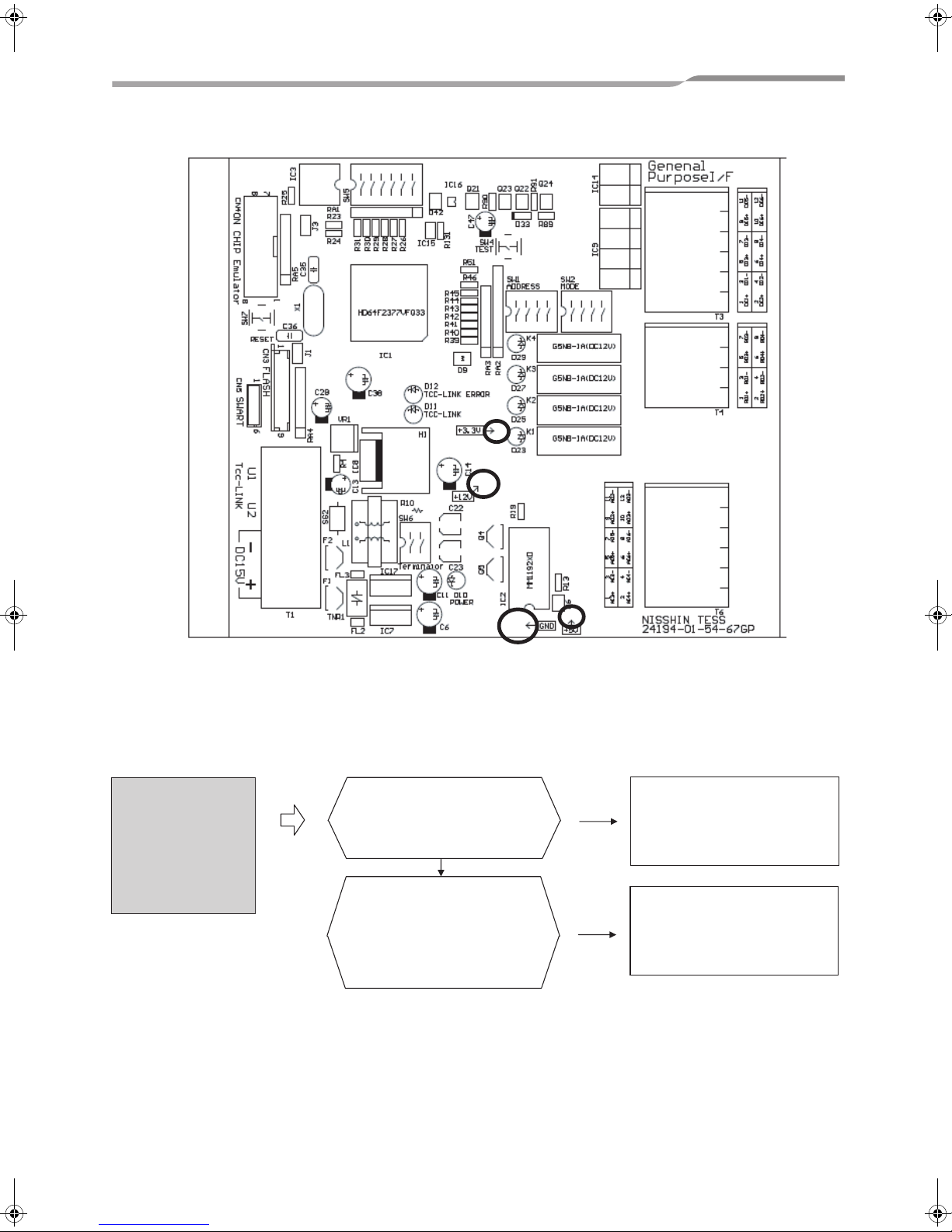
In troubleshooting procedures described in Section 4 or later, you need to check the settings, connections, and
LEDs of the board inside the case.
Disconnect the DC plug of the AC adapter, remove the screws located in the four corners of the case lid, and open
the lid of the case. Connect the DC plug again, and turn on the unit.
5
TCS-NET General Purpose Interface
Service Manual
4. Troubleshooting
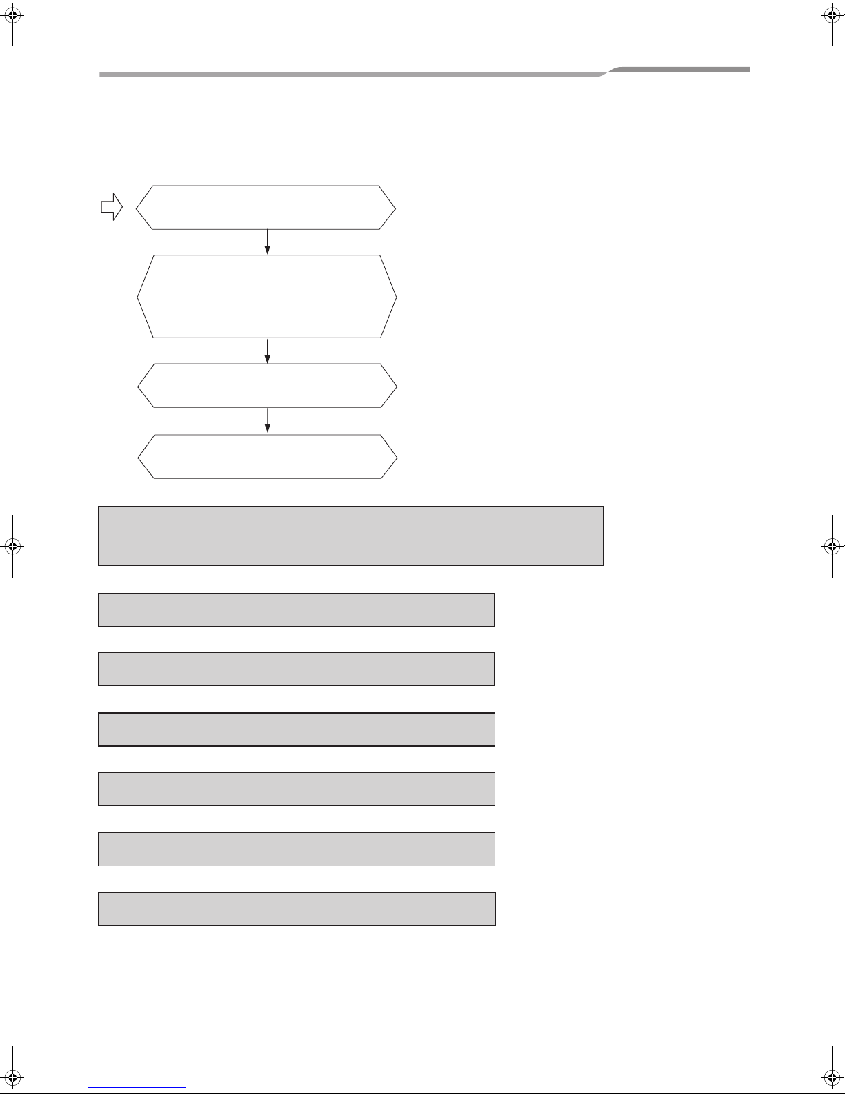
Follow the flowchart show in 4-1to perform common checks that apply to every kind of troubleshooting.
Is an appropriate AC adapter used?
Are the voltage and polarity set correctly?
YES
Is the TCC-LINK connection (U1 and U2)
made correctly?
Is the address set correctly (SW1 and
SW2)?
YES
Is the board operating normally in test
mode?
YES
Are wires for functions to be used
connected to the terminal block securely?
Troubleshoot following problems by using the applicable procedure shown in 4-2 and its following.
An air conditioning operation connected to the RO1 relay contact is not available from the
central remote controller. Refer to 4-2.
Air conditioning conjunction function is not available. Refer to 4-3.
Temperature can not be measured. Refer to 4-4.
RO1, RO2, RO3, and RO4 cannot be controlled. Refer to 4-5.
DI input is unreadable. Refer to 4-6.
AO output is not produced. Refer to 4-6.
AI input is unreadable. Refer to 4-6.
Details are described in the following sections using flowcharts.
6
TCS-NET General Purpose Interface
Service Manual
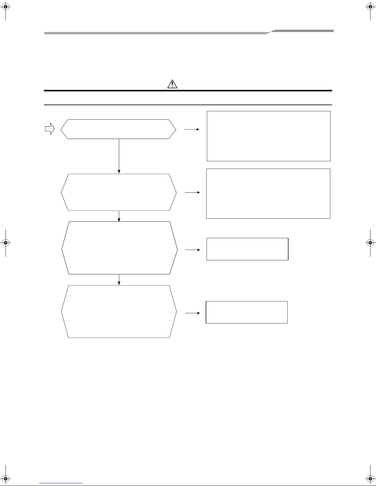
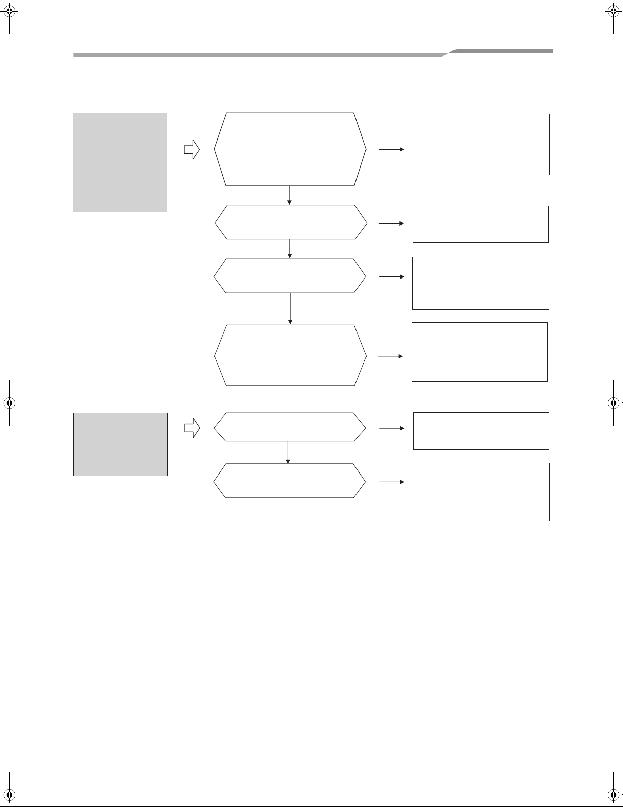
4-1. Common Checks
Be sure to always perform the checks shown in the flowchart below when a problem occurs.
CAUTION
The changes to DIP SW settings take effect after the SW7 RESET button is pressed or the unit is turned on again.
Is an appropriate AC adapter used?
Are the voltage and polarity set correctly?
YES
Is the TCC-LINK connection (U1 and U2)
made correctly?
Is the address set correctly (SW1 and
SW2)?
YES
Is the board operating normally in test
mode?
To enable test mode, set SW2 as follows:
1 and 4 to ON; 2 and 3 to OFF.
The D23, D24, D25, and D26 LEDs must
be turned ON/OFF according to whether
each bit of SW1 is ON or OFF.
YES
Are wires for functions to be used
connected to the terminal block securely?
Visually check the terminal block to see if
the stripped part of each wire is correctly
placed between the contacts. Check
continuity between each contact of the
terminal block and the end of the
corresponding wire with a tester.
NO
NO
NO
NO
Use an appropriate power supply. Check that
the POWER LED (LED D10) is lit in red.
Check that the DC plug input is 15±0.5v.
Check the voltages of 3.3V, 12V, and 5V
with a tester as necessary. See the PCB
layout diagram below that shows the
locations of the checkpoints.
Make the connection correctly, and use an
appropriate address.
For details, see Chapters 5 and 6 of the
Installation Manual.
Check the termination resistance setting of
SW6 also.
Replace the product.
Connect the wires to the
terminal block securely.
7
TCS-NET General Purpose Interface
The PCB layout is shown below. Checkpoints are circled.
Service Manual
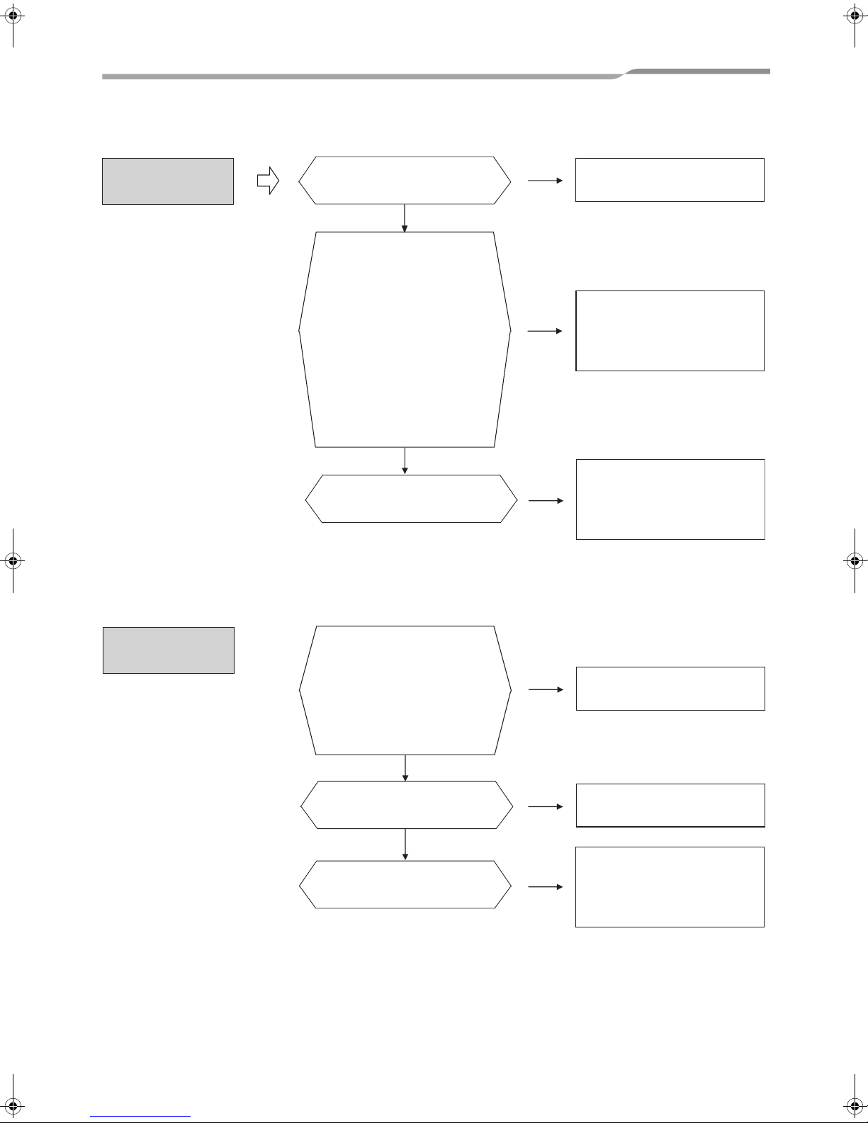
4-2. An air conditioner indoor unit connected to the RO1
and DI3 relay contacts using the HA connector cannot
be operated from the central remote controller
An air
conditioning
operation
connected to the
RO1 relay contact
is not available
from the central
remote controller
Is the relay mode set correctly
(SW5)?
SW5-2 and SW5-4 = OFF;
SW5-3 = ON
YES
Are DI3/RO1 and the air
conditioner HA connector
connected correctly?
See the chapter titled "WIRING"
of the Installation Manual.
NO
NO
See the Installation Manual,
and make the settings
correctly.
See the Installation Manual,
and make the connection
correctly.
8
TCS-NET General Purpose Interface
4-3. Conjunction function is not available
Service Manual
Conjunction function
cannot be set, or air
conditioning
operation is not
available.
(Using the setting
tool software for the
advanced
conjunction function)
Conjunction
function is not
available.
DI4/DI1 fixed trigger
mode
Is the setting tool software for
advanced conjunction function
installed on the configuration PC?
Is the connection to the TCBIFCG1TLE made correctly? Are
values written correctly?
YES
Is the setting value of SW5
correct?
YES
Are the input polarity and level
specified for the trigger port
provided correctly?
YES
Is the address for central control
of the specified air conditioner
correctly registered using the
setting tool software for
advanced conjunction function?
Is the setting value of SW5
correct?
YES
Are inputs to DI4 and DI1
provided correctly?
NO
NO
NO
NO
NO
NO
See the setting tool manual for
advanced conjunction
function, and install the
software and make the
connection correctly.
Make the following
settings: 6 POSITION =
ON; 5 POSITION = OFF.
See the Installation Manual,
and set the polarity, voltage
level, and current level of the
specified trigger port.
See the setting tool manual for
advanced conjunction
function, and set the address
of the applicable air
conditioner correctly.
Make the following
settings: 5 POSITION =
ON; 6 POSITION = OFF.
See the Installation Manual,
and check that the connection
is made securely and an
appropriate input current level
and polarity are provided.
9
TCS-NET General Purpose Interface
Service Manual
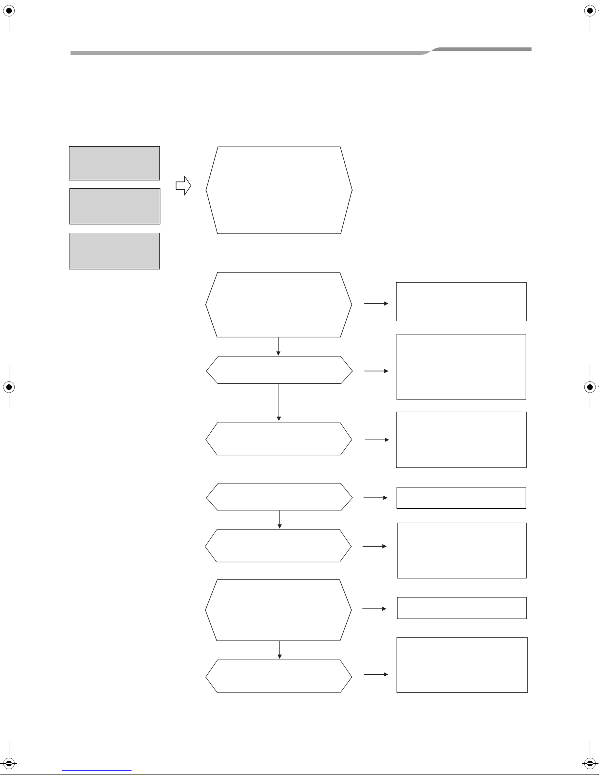
4-4. Temperature measurement can not be measured
Temperature
measurement can
not be measured
Is the specified thermistor
connected to AI3 or AI4
correctly?
YES
Connect the DYNA KIT to CN5.
Set SW2 as follows: 1 and 4 to
ON; 2 and 3 to OFF. Press
RESET SW7. Test mode is
enabled. Start the
communication software on the
PC, and display the
communication log in ASCII
format. The calculated
resistance value of the
thermistor connected to AI3/4 is
displayed at intervals of 1
second. Check that the value is
correct by comparing it to the
specified value.
YES
Are the TCB-IFMB640TLE and
Modbus Master operating
normally?
NO
NO
NO
Connect it correctly.
Replace the wire with a
shielded one, or avoid
induction from other wires.
Check the operation of the
TCB-IFMB640TLE and
Modbus Master.
For details, see the manual of
each device.
4-5. A relay contact cannot be controlled from the center
controller
RO1, RO2, RO3,
and RO4 cannot be
controlled
Is the board operating normally
in test mode?
To enable test mode, set SW2
as follows: 1 and 4 to ON; 2
and 3 to OFF.
The D23, D24, D25, and D26
LEDs must be turned ON/OFF
according to whether each bit
of SW1 is ON or OFF.
YES
Can the output pattern of RO1
and RO2 be set with SW5-1, 2,
and 3?
YES
Are the TCB-IFMB640TLE and
Modbus Master operating
normally?
NO
NO
NO
Replace the product.
Replace the product.
Check the operation of the
TCB-IFMB640TLE and
Modbus Master.
For details, see the manual of
each device.
10
TCS-NET General Purpose Interface
Service Manual
4-6. The port I/O value is unreadable or the port output
value is not produced when the center controller is
used
DI input is
unreadable
AO output is not
produced
AI input is
unreadable
For DI:
Connect the DYNA KIT to CN5.
Set SW2 as follows: 1 and 4 to
ON; 2 and 3 to OFF. Press
RESET SW7. Test mode is
enabled. Start the
communication software on the
PC, and display the
communication log in ASCII
format.
In test mode, are the DI1, DI2,
DI3, DI4, DI5 and DI6 levels
displayed as H or L correctly
according to the actual input in
the communication software on
the PC?
YES
Are the applied current value
and polarity provided correctly?
YES
Are the TCB-IFMB640TLE and
Modbus Master operating
normally?
NO
NO
NO
Check the input from the
external circuit and the
connection.
Check the input from the
external circuit and the
connection. For the applied
current value, refer to the
regulation value in the
installation manual.
Check the operation of the
TCB-IFMB640TLE and
Modbus Master.
For details, see the manual of
each device.
For AO:
For AI:
In test mode, is 5 V output to
AO2 and AO3?
YES
Are the TCB-IFMB640TLE and
Modbus Master operating
normally?
In test mode, measure the AI5
and AI6 input values with a
tester. Are they displayed at
1024 level in the communication
software on the PC?
YES
Are the TCB-IFMB640TLE and
Modbus Master operating
normally?
11
NO
NO
NO
NO
Replace the product.
Check the operation of the
TCB-IFMB640TLE and
Modbus Master.
For details, see the manual of
each device.
Replace the product.
Check the operation of the
TCB-IFMB640TLE and
Modbus Master.
For details, see the manual of
each device.

DE89308801
Copyright © 2009 TOSHIBA CARRIER CORPORATION, ALL Rights Reserved.
23-17, TAKANAWA 3-CHOME, MINATO-KU, TOKYO, 108-0074, JAPAN
 Loading...