

Toshiba TCB-EXS21TLE INSTALLATION MANUAL
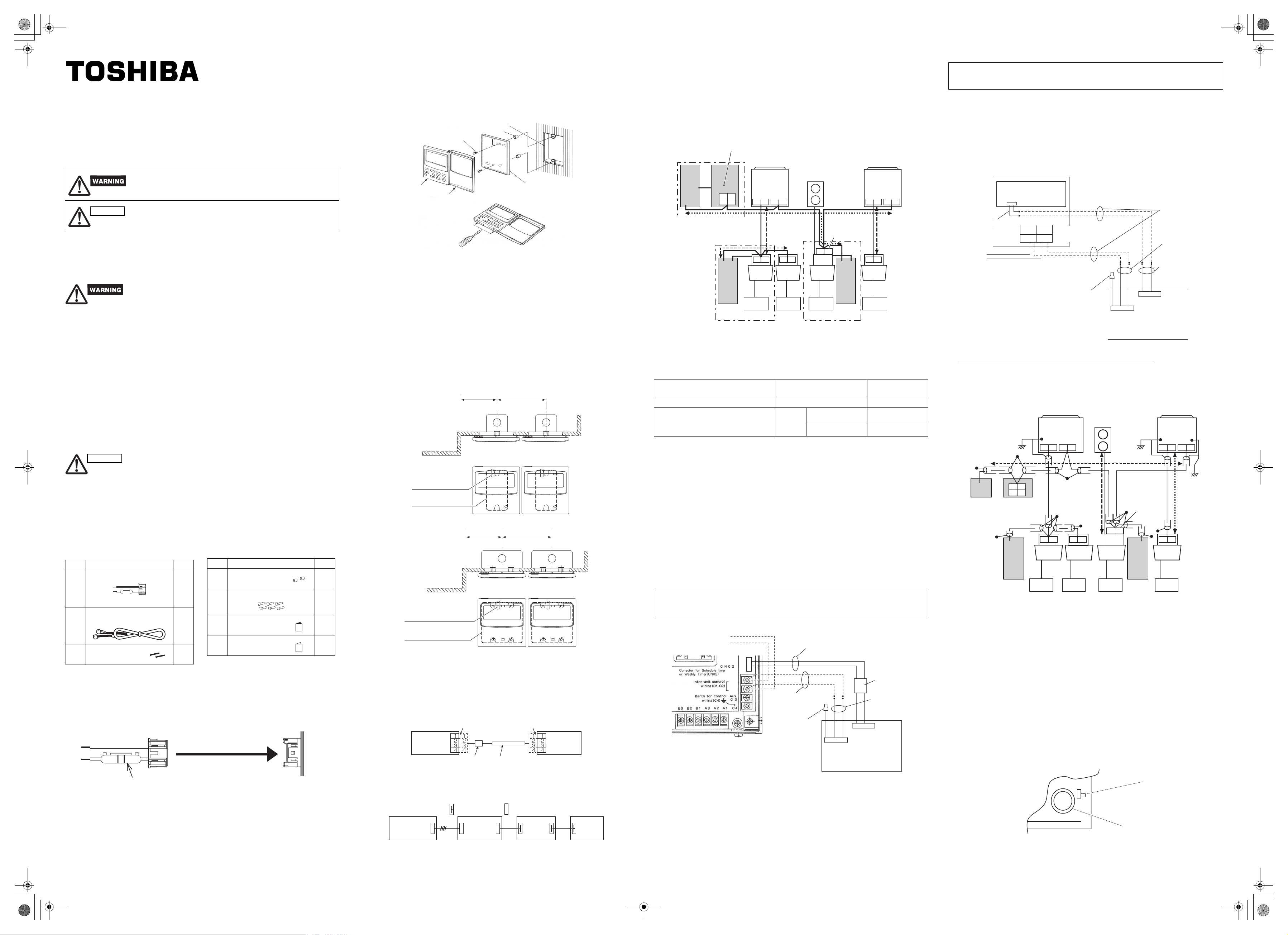
Fig.11
+01E_073002_STime_EXS21TLE.fm Page 1 Friday, January 25, 2008 4:50 PM
INSTALLATION INSTRUCTIONS Model TCB-EXS21TLE
INFORMATION FOR THE PERSON IN CHARGE OF INSTALLATION (ELECTRICAL) WORK AND SERVICING
Safety Precautions
● Read these Safety Precautions before beginning installation or electrical work, and
perform the work only in the correct manner.
● Precautions in this manual are given in the form of “Warnings” or “Cautions.” Both types
of precautions contain important information related to your safety, the safety of users,
and the correct operation, installation, or maintenance of the air conditioning system. Be
sure to carefully observe all relevant precautions.
This symbol refers to a hazard or unsafe practice which can result
in severe personal injury or death.
CAUTION
This symbol refers to a hazard or unsafe practice which can result
in personal injury or product or property damage.
When installation work is completed, perform a test run and check that no trouble occurs.
Also be sure to explain the methods for using the product to the customer, based on the
contents of the Operation Manual. In addition, request that the customer keep and
conveniently store the “Information for the Person in Charge of Installation (Electrical) Work
and Servicing” together with the Operation Manual.
● Request installation and electrical work only from the dealer or a qualified air
conditioning specialist.
Attempting to carry out installation work on your own, and doing so incorrectly, may
result in electrical shock, fire, or other hazards.
● Installation procedures must be performed correctly, carefully following the instructions
in this document.
Failure to do so may result in electrical shock, fire, or other hazards.
● Electrical work must be performed by a qualified electrician. It must be performed in
accordance with technical standards related to electrical equipment, interior wiring
regulations, local codes, and the contents of these instructions. Be sure to use a
dedicated power supply circuit.
Insufficient power circuit capacity or improper electrical work may result in electrical
shock or fire.
● Use only the designated cables for wiring, and connect them securely. Fasten cables so
that no external force is applied to the terminal connections.
Insufficient connections or cable fastening may result in heat generation, fire, or other
hazards.
CAUTION
● Depending on the installation location, it may be necessary to install an earth leakage
breaker. Failure to do so may result in electrical shock or fire.
● Do not install in kitchens, workshops, or other locations where there is oil mist in the air.
● Do not install next to windows or in other locations exposed to direct sunlight or in direct
contact with outside air.
● Do not install near an elevator, automatic door, industrial sewing machine, or other
devices that can be expected to produce electrical noise.
Accessories for Schedule Timer
No. Supplied parts Q'ty
CN61 (T10) power wire
1
1
(with current fuse) *1
1.2m length of connecting
2
3
wire *2
Screws
M4 × 25
1
2
*1 If the fuse blows as a result of a wiring short-circuit, miswiring, or overcurrent, replace it with a
125 V, 0.1 A fuse (Fig. 1).
*2 Use this connecting wire when using with weekly timer mode. Connect the provided
connecting wire (4 cores) to the power terminal (4P connector) of the schedule timer unit.
(Fig. 5)
Fig. 1
1. Power wire
Fuse
No. Supplied parts Q'ty
4
Spacers
2
Wire joints
5
6
7
Operation
manual
Installation
manual
6
2
1
Indoor unit control PCB CN61
(T10) connector (6P orange)
Installing the Schedule Timer
<Note 1> Avoid twisting the inter-unit control wiring or the input/output wiring together with
power or other wiring, and avoid running them in the same metal conduit. Doing
so can cause malfunction.
<Note 2> Install the schedule timer at a location away from any sources of electrical noise.
<Note 3> Install a noise filter or take other appropriate action if electrical noise affects the
power supply circuit of the unit.
Fig. 2
Switch box for 1 switch (no cover)
or switch box for 2 switches (no cover)
M4 x 25 small
Spacer
flat-head screws (2)
Schedule
timer unit
Decorative
Under-case
(back case)
cover (panel)
(1) Open the panel on the schedule timer unit. Insert a standard (flathead) screwdriver or
similar tool into the notches on the bottom of the schedule timer unit to open and
remove the back case.
(2) Use the 2 supplied M4 small screws and install the schedule timer back case onto the
switch box. Before installing, use a screwdriver or similar tool to press on and open the
screw holes that correspond to the JIS box that is used.
When fastening the case, use spacers and do not tighten the screws too much. If the
schedule timer does not fit tightly against the wall, cut the spacers as required to make
adjustments.
(3) Connect the supplied power wire (2-core) and inter-unit control wire (3-core) to the
schedule timer unit.
(“Wiring for Weekly Timer mode”)
(4) Align the schedule timer unit with the tabs on the back case and press to install it.
Installation of connected schedule timers
● When installing schedule timers (remote controller switches, system controllers, etc.)
onto the wall, use the method shown in Figs. 3 and 4.
Fig. 3
Remote controller
wiring outlet
Switch box for 1
switch (no cover)
Fig. 4
Remote controller
wiring outlet
Switch box for 2 switches
(no cover)
More than
95 mm
(From wall) (For connected
More than
95 mm
(From wall)
More than 125 mm
installation)
More than
125 mm
(For connected
installation)
* For maintenance reasons, leave a gap of 25 mm or more between the remote controller switch
and schedule timer if they are arranged in parallel above/below each other.
This remote controller has two methods of usage with the weekly timer and the
schedule timer.
The wiring method and switch setting are different in each case.
Wiring for Weekly Timer mode
● Wiring Diagram (Be sure to use the provided wires for the connection wiring.)
Fig. 5
Schedule
timer
Clamp filter
● Location The schedule timer and wired remote controller can be located on
either the right and left.
● System Diagram
Fig. 6
Schedule
timer
: Terminal board
DC12V
4 wires
Wired
remote
controller
Timer terminalPower terminal
Connecting wire
(accessory)
: Connector
Indoor
unit
Wired
remote
controller
Outdoor
unit
Wiring for the Schedule Timer mode
<Basic Wiring Diagram>
Fig. 7
Wiring
specifications (1)
P1
To power terminal
To communication
terminal
Schedule timer *1
*1 In the case the schedule timer is connected to the 64 system central remote controller or
ON-OFF controller
*2 In the case the schedule timer is connected to the indoor unit for S-MMS
*3 In the case the schedule timer is connected to the TCC-LINK adapter
Wiring Max. Length Electric cable
P1: Power wire for schedule timer 100m 0.5mm
L1: Central control system wiring
L2,L3,L4: Indoor/Outdoor communication
line
P1, L1, L2, L3 and L4 have no polarity.
<Note> ● This schedule timer is device connected to TCC-LINK.
● The maximum number of schedule timer units that can be connected is 8. (A
maximum of 10 schedule timer units and other central control devices can be
connected.)
● In the case of SDI/DI, an extra TCC-LINK adapter may be required.
● Wiring
● The schedule timer wiring can be connected by the following two methods. Select one of
these connection methods according to the actual installation location. When wiring,
extend the lengths of the wires using wire joints (accessory) and extension wires (field
supply).
<Note> ● When installing multiple schedule timers, avoid the use of
communication line.
● Connection diagram (Be sure to use the provided wires as the power
wiring.)
Wiring specifications (1)
If a 64 system central remote controller (or ON-OFF controller) is installed (power is
supplied from the 64 system central remote controller):
Fig. 8
64 system central remote controller
(Back side)
● Wiring procedures Connect the provided connecting wire to the power terminal (4P
● The power wiring and communication wiring has no polarity.
64 system central remote controller or
ON-OFF controller
Refrigerant system 3
(S-MMS)
P1
To power terminal
To communication
terminal
Schedule
timer *3
Outdoor unit
(Header unit)
U2
U1
U2
U1
Indoor
unit
Remote
controller
U3
U4
U4
U3
U2
U1
L3
To power terminal
To communication
terminal
Schedule
timer *2
Refrigerant system 1
(S-MMS)
Indoor unit
(Header unit)
U1U2U3
L2 L4
U2
U1
P1
Indoor
unit
Remote
controller
U4
L1
U2
U1
Indoor
unit
Remote
controller
Refrigerant system 2
(SDI/DI)
Outdoor unit
TCC-LINK
adapter
U4
U3
Indoor
unit
Remote
controller
Wiring specifications (2)Wiring specifications (2)
specifications
2
L1+L2+
L3+L4
Inter-unit control wiring
U1
U2
Field supply
Wire joint
(Not used)
Less than 1000m MVVS 1.25mm
Less than 2000m MVVS 2.0 mm
Connecting wire (accessory)
Clamp filter
Communication
wiring
BlueBlue Pink
Communication
terminal (3P connector)
Schedule timer
(blue + pink)
Power terminal
(4P connector)
connector) of the schedule timer.
The terminal attached to the clamp filter must be connected to the
schedule timer.
Wiring specifications (2)
If a 64 system central remote controller (or ON-OFF controller) is not installed (power is
supplied from the indoor unit):
<Note>
(1) The only functions of the schedule timer are indoor unit ON/OFF and remote
controller enable/disable operations.
(2) It is required that during installation, a 64 system central remote controller or wired
remote controller be installed next to the schedule timer so that operation mode
and other information can be checked.
(3) If the 64 system central remote controller or other central control device is not
present, the schedule timer cannot be used in combination with a system that does
not utilize remote controllers including high wall (KRT series) systems.
Fig. 9
Indoor unit control PCB
CN61(T10)
Field supply
1. Supplied parts
U3
U1
Indoor/Outdoor units communication line
(for S-MMS)
Central control system wiring
(for SDI/DI)
U4
U2
(for SDI/DI)
(for S-MMS)
Wire joint
(Not used)
BlueBlue Pink
Communication
terminal (3P connector)
Schedule timer
Communication
wiring
(blue + pink)
Power wiring
(black + white)
Black White
Power terminal
(4P connector)
● The power wiring and communication wiring has no polarity.
● The length of the power wiring must be no more than 100 m.
The ground method of a shield wire (when using with the Schedule
Timer)
Fig. 10
2
2
*4
Power
terminal
Schedule
Timer *1
*1 In the case the schedule timer is connected to the 64 system central remote controller or
ON-OFF controller
*2 In the case the schedule timer is connected to the indoor unit for S-MMS
*3 In the case the schedule timer is connected to the TCC-LINK adapter
<Grounding of the shield wires>
● The shield wires of the central control wiring should be connected at closed end, and
these should be single-point ground.
● The terminal end (*4) of the shield wires should be open and insulated.
Shield wiring for
central control
system (singlepoint earth)
U3
U1
64 System central
remote controller
ON-OFF controller
*4
Communication
Schedule
Timer *2
Refrigerant system 1
(S-MMS)
U4
U2
or
terminal
Remote
controller
Outdoor unit
(Header unit)
U1U2U3
communication line
U2
U1
Indoor
unit
U4
Indoor/Outdoor
units
*4
U2
U1
Indoor
unit
Remote
controller
Refrigerant
system 2
(SDI/DI)
U3
Indoor
unit
Remote
controller
Shield wiring for
central control
system (singlepoint earth)
Outdoor
unit
Central control
system wiring
TCC-LINK
adapter
U4
Schedule
Timer *2
Refrigerant system 3
(S-MMS)
Outdoor unit
(Header unit)
U2
U1
*4
U2
U1
Indoor
unit
Power terminal
Remote
controller
U4
U3
Indoor/Outdoor units
crcommunication line
Shield wiring for central control system
(single-point earth)
Explanation to Customers
● After work is completed, present the Operation Manual and Information for the Person in
Charge of Installation (Electrical) Work to the customer.
● Explain to the customer the methods for use of the system, as described in the
Operation Manual.
Memory Backup Switch
After installation is completed, check that the backup switch on the reverse side of the
schedule timer PCB is turned to ON.
(The backup battery will retain the current time for up to 100 hours.)
OFF
ON
Backup switch
Backup battery
(E)
2
3
6
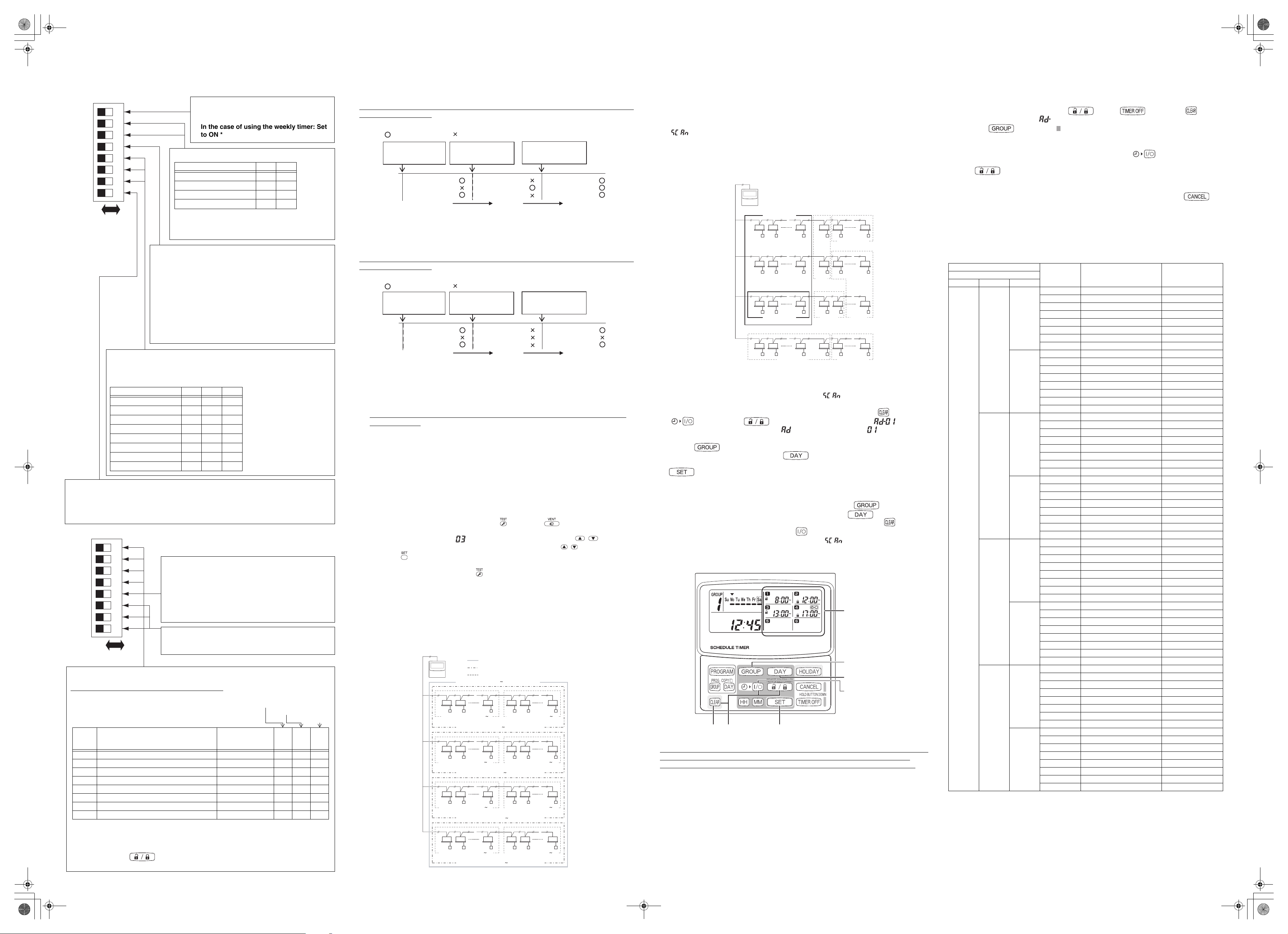
+01E_073002_STime_EXS21TLE.fm Page 2 Friday, January 25, 2008 4:50 PM
When using with the Weekly Timer, all switch settings should be OFF except S41-1.
About the Setting Switches
● Complete the switch settings before turning ON the schedule timer power.
S41
1
2
3
4
5
6
7
8
OFF ON
*
These switches are all
OFF at the time of
delivery.
Central Control Main/Sub
Switching (4)
Function selector switch (1) settings
• In the case of using the schedule timer:
Set to OFF
• In the case of using the weekly timer: Set
to ON *
Timer Group Settings (2, 3)
Function 2 3
1 timer group – fixed OFF OFF
4 timer group – fixed OFF ON
8 timer group – fixed ON OFF
Manual group setting ON ON
For details of the timer groups, refer to the Creating
Timer Groups when using the Schedule Timer as
described in below.
Sub: OFF
Main: ON
(Central Control Devices center/ Terminal switching)
(1) Set to “sub” (OFF) when using together with the 64 system
central remote controller. (Factory setting: Sub)
(2) Set to “main” (ON) when using together with an ON-OFF
controller, wired remote controller or wireless remote
controller.
* When using with multiple schedule timer units, set only
1 unit to “main” (ON) and set the remainder to “sub”
(OFF).
Schedule Timer Address Settings (5, 6, 7)
A maximum of 8 schedule timer units can be connected to the inter-unit
control wiring (central control wiring). If multiple units are connected, use the
setting switches and allocate the addresses, taking care to avoid duplication.
Address 5 6 7
Address 1 OFF OFF OFF
Address 2 OFF OFF ON
Address 3 OFF ON OFF
Address 4 OFF ON ON
Address 5 ON OFF OFF
Address 6 ON OFF ON
Address 7 ON ON OFF
Address 8 ON ON ON
Holiday and Operation Disable Settings for Each Group (8).
When this switch is set to OFF, units are all controlled together. When this switch is ON, the
units are controlled by the settings for each timer group.
(For details of the timer groups, refer to the Creating Timer Groups when using the Schedule
Timer as described in below.)
S42
1
2
3
4
5
6
7
8
OFF ON
*
These switches are all OFF
at the time of delivery.
● The following switch setting is required when selecting remote controller enable/disable
button to enable with the schedule timer.
Remote controller disabled item Switch (2, 3, 4)
When remote controller enable/disable is used with the schedule timer, set the remote controller item switches 2,
3 and 4 to the specific item according to the following items.
OFF: No setting
ON: Setting
Remote controller disabled items
Mode 0 Remote controller enable/disable not used No indication OFF OFF OFF
Mode 1 Start/stop Central 1 OFF OFF ON
Mode 2 Operation mode Central 4 OFF ON OFF
Mode 3 Operation mode + Start/stop Central OFF ON ON
Mode 4 Temperature setting Central ON OFF OFF
Mode 5 Temperature setting + Start/stop Central ON OFF ON
Mode 6 Temperature setting + Start/stop Central 3 ON ON OFF
Mode 7
Temperature setting + Operation mode + Start/stop
• All switch settings should be set to OFF when enable/disable is not used.
•
Central 1 – 4 are the designations for the remote-controller disable modes for the 64 system central remote
controller.
• After the above setting is completed, perform the enable/disable setting using the
remote controller button with schedule timer. For more information, refer to
[Setting Up Programmed Operations] in the Operation Manual of the Schedule Timer.
Simultaneous time
communications (5)
Disabled: OFF
Enabled: ON
When multiple schedule timers are installed, set this
switch to ON to perform time settings for multiple units
simultaneously. One minute after the time is set, the time
at the other schedule timers will change to match the set
time. (Ordinarily this switch is set to OFF.)
Spare (6, 7, 8)
Be sure that these switches are OFF when the system is
used.
2: Temperature setting
3: Operation mode
64 system central
remote controller
indication
Central ON ON ON
234
4: Start/stop
::: Continue from the previous section :::
Remote Controller Enable Items Switch (1) (Substitute/Addition Selector)
OFF: (Substitute mode)
All setting contents will be substituted to setting contents using the remote controller disabled item
switches 2, 3 and 4 as opposed to the remote controller enable/disable items in setting presently.
Example: In the case of setting to [Mode 5] during remote controller disabled item (Temperature
setting+ Start/stop mode)
Use to remote controller
: Setting changeable : Setting cannot be changed
Set to central 4 with the
64 system central
controller
Temperature setting
Operation mode
Start/Stop
Change to all of the setting items
with switches
Set to remote controller
disabled item via the
timer
Temperature setting
Operation mode
Start/Stop
Set to remote controller
enabled item via the
timer
Temperature setting
Operation mode
Start/Stop
Enable all items independently of
determined by setting switches
ON: (Addition mode)
Items set to ON using the remote controller disabled item switches 2, 3 and 4 will be added to the
remote controller enable/disable items in the current setting.
Example: In the case of setting to [Mode 5] during remote controller disabled item (Temperature
setting+ Start/stop mode)
Use to remote controller
: Setting changeable : Setting cannot be changed
Set to central 4 with the
64 system central
controller
Temperature setting
Operation mode
Start/Stop
Disabled addition with switch
setting items only (Temperature
setting + Start/stop)
Set to remote controller
disabled item via the
timer
Temperature setting
Operation mode
Start/Stop
Set to remote controller
enabled item via the
timer
Temperature setting
Operation mode
Start/Stop
Enabled addition with switch
setting items only (Temperature
setting + Start/stop)
Setting Central Control Addresses when using with the Schedule
Timer
● When using the schedule timer, central control addresses setting of the indoor
unit is required.
(If central control address of the indoor unit has not been set, the schedule timer cannot be
used to start and stop these units normally. Therefore, be sure to set the central control
addresses of the indoor unit before turning on the power of the schedule timer.)
(1) Turn on the power of all the indoor units.
(2) Confirm the setting for the system addresses, indoor addresses and group addresses
of all indoor units. If a wrong setting is found, reset the system addresses, indoor
addresses and group addresses correctly.
(3) Perform the address settings that turn off the power of the indoor units.
• Central control address setting using the wired remote controller
<Perform the following procedures, 1 to 5, to all the indoor units>
1. Press and hold the wired remote controller button and button for at least 4
seconds.
2.
Assign the item code (DN) to
using the temperature setting button
/.
3. Set the desired control address (1 to 64) using the timer button / .
4. Press the button.
(Confirm the remote controller indication changes from flashing to fully lit.)
5.
After setting is completed, press the
button and then return the unit to general off status.
(In this case, it will take about 1 minute for normal remote controller operation to resume.)
<Central control address setting using the 64 system central remote controller>
Refer to the [Address switch setting] in the [Installation manual of 64 system central remote
controller] that is supplied to the 64 system central remote controller.
Creating Timer Groups when using the Schedule Timer
● The schedule timer can be used to create up to 8 timer groups (8 zones).
<Setting fixed timer groups (zones)>
Fig. 12
Schedule
timer
Central control address 1 64 (Group (Zone) 1)
1
Central control address 1 8
(Group (Zone) 1)
18
17
Central control address 17 24
(Group (Zone) 3)
33 34
Central control address 33 40
(Group (Zone) 5)
49 50
Central control address 49 56
(Group (Zone) 7)
1 fixed timer group (1 setting zone) (64 units together)
4 fixed timer group (4 setting zone) (16 units together)
8 fixed timer group (8 setting zone) (8 units together)
2
Central control address 1 16 (Group (Zone) 1)
Central control address 17 32 (Group (Zone) 2)
Central control address 33 48 (Group (Zone) 3)
Central control address 49 64 (Group (Zone) 4)
8
24
40
56
9
Central control address 9 16
25
Central control address 25 32
41
Central control address 41 48
57
Central control address 57 64
10
(Group (Zone) 2)
26
(Group (Zone) 4)
42
(Group (Zone) 6)
58
(Group (Zone) 8)
16
32
48
64
● Procedure for making fixed timer group settings (zone)
(1) First, use a 64 system central remote controller or the wired remote controllers to set
the central control addresses, as assigned in the figure above, to the indoor units that
will be subject to group timer control.
(2)
Next, use S41 switches 2 and 3 to set the number of timer groups (zones) you wish to
create.
(For setting of switches 2 and 3, refer to the [About the Setting Switches] item above.
(3) Finally, turn on the schedule timer power. Initial communications are performed.
( flashes in the display.) The normal display appears after several minutes, and
the timer group settings are confirmed.
<Procedure for making manual timer group settings (zone)>
Manual timer group settings allow central control addresses to be assigned freely within the timer
groups such as the setting example below.
Fig. 13
Setting example
● Procedure for making manual timer group settings (zone)
(1) Turn on (manual settings) S41 setting switches 2 and 3, then turn on the power.
Restart and initial communications are performed. ( flashes in the display.) The
normal display appears after several minutes.
(2) When the normal display appears, press and hold the schedule timer button, the
button, and the button
flashing, in the present time display. ( indicates “address” and is the central
address number.)
(3) Use the button
programmed operation. Then use the button
select the central control address to assign and register for that timer group. Press the
button
control address appears on the [Timer program] display area of the schedule timer.)
(4) To continue registering addresses, repeat step (3). Central control address numbers
will be added to the right side on the [Timer program] display area of the schedule
timer. To cancel a registered central control address, use the button
Setting buttons area to select the timer group, then use the button
Setting buttons area to select the central control address and press the button
(5) When registration is completed, press the button
automatically and performs initial communications. ( flashes in the display.) The
normal display appears after several minutes, and the manually assigned timer group
settings are confirmed.
4 to register the selected central control address. (Registered central
Schedule timer
(Group (Zone) 1)
1
18
17
33 34
(Group (Zone) 4)
49 50
2
8
24
40
56
25
(Group
(Zone))
41
(Zone) 5)
57
9
(Group
10
(Group (Zone) 3)
26
42
(Group
(Zone) 6)
58
(Group (Zone) 8)(Group (Zone) 7)
16
32
48
64
1 for 4 seconds or longer. “ ” appears,
2 in the Setting buttons area to select the timer group for
3 in the Setting buttons area to
2 in the
3 in the
6. The schedule timer restarts
5.
Fig. 14
Timer program display
area
154
• During manual timer group settings, the schedule timer can be used to create up to 8 groups (8
zones), and the central control addresses can be registered up to 64 units in 1 group (1
zone).In addition, one of the central control addresses can be set in multiple timer groups.
(Indoor units of the central control address 33-40 are performed to start/stop and enable/
disable operation according to the programmed operation for both timer group (zone) 1 and 4
to illustrate with reference to the thick frame marking as shown in above setting example of
Fig. 13)
Checking the Central Control Addresses and Operating the Units
that are Controlled by the Schedule Timer
● The schedule timer communicates with the indoor units to check which central control
addresses can be controlled with the current timer control.
The schedule timer can then be used to start and stop these units.
(1) Press and hold the schedule timer button, button, and button
for 4 seconds or longer. “ (central control address)” appears in sequence, blinking.
(2) Use the button in the area to display the blinking central control addresses
in sequential order. In this way, it is possible to check which central control addresses
in the displayed timer group can be operated by the timer.
(3) With the selected timer group displayed, press the timer button. Each time the
button is pressed the indoor units in the displayed timer group start or stop. Pressing
the button in this mode permits all items (operation start/stop, operation
mode, temperature setting items) at the indoor units in the displayed timer group where
remote controller prohibit is in effect.
(4) After checking the addresses and operating the units, press and hold the
button for 2 seconds or longer. The schedule timer display returns to the normal
display and all controllable indoor units stop.
Installation Work Plan
● Use the wired remote controller to check the unit No. of the indoor units.
(Start the A/C unit with the wired remote controller, then press the remote controller
UNIT SELECT button once to display the unit No. of the master unit.)
Schedule timer Central
148
1
1
2
3
2
4
1 At the
time of
shipment
5
3
6
7
4
8
control
addresses
1–,–
2–,–
3–,–
4–,–
5–,–
6–,–
7–,–
8–,–
9–,–
10 – , –
11 – , –
12 – , –
13 – , –
14 – , –
15 – , –
16 – , –
17 – , –
18 – , –
19 – , –
20 – , –
21 – , –
22 – , –
23 – , –
24 – , –
25 – , –
26 – , –
27 – , –
28 – , –
29 – , –
30 – , –
31 – , –
32 – , –
33 – , –
34 – , –
35 – , –
36 – , –
37 – , –
38 – , –
39 – , –
40 – , –
41 – , –
42 – , –
43 – , –
44 – , –
45 – , –
46 – , –
47 – , –
48 – , –
49 – , –
50 – , –
51 – , –
52 – , –
53 – , –
54 – , –
55 – , –
56 – , –
57 – , –
58 – , –
59 – , –
60 – , –
61 – , –
62 – , –
63 – , –
64 – , –
Indoor unit Unit No.
System - Indoor
Room nameFixed timer group
85464369073002 (E)
 Loading...