

Toshiba TCB-AX32E2 Installation Manual
INSTALLATION MANUAL
To Personnel Charged in Installation Work and Service
Wireless remote controller kit
Model: TCB-AX32E2
EB01800301 (EN)
• Thank you for purchasing Wireless remote controller kit TOSHIBA packaged air
conditioner.
• Read this manual carefully for correct installation of the wireless remote controller
kit before starting work.
• After the installation is completed, execute a test run to check for normal operation
and explain how to use and maintain the wireless remote controller kit to the
customer according to the Owner’s Manual.
Ask the customer to keep this manual with the Owner’s Manual.
Observe the safety precautions described in the Owner’s Manual of the wireless
remote controller kit, Installation Manual and Owner’s Manual of the indoor unit.
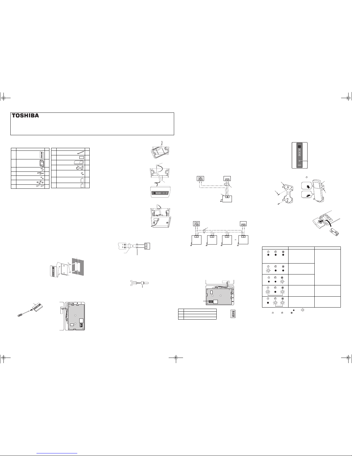
Accessory Parts
Installation Location of Signal Receiving Unit
• Do not install in a location where the air contains oil mist, such as in a kitchen or
factory.
• Do not install next to a window, or in any other location directly exposed to sunlight
and outside air.
• Do not install nearby devices which can be expected to produce electrical noise,
such as elevators, automatic doors, and industrial sewing machines.
• If the Signal receiving unit is installed near a rapid-start type or inverter-type
fluorescent lamp (a lamp which does not include a glow lamp), it may not be
possible to receive the wireless remote controller signal in some cases. In order to
prevent interference from fluorescent lamps, leave a minimum of 2 m between the
Signal receiving unit and the fluorescent lamps, and install the Signal receiving
unit in a location where it can receive the wireless remote controller signal when
the fluorescent lamps are lit.
How to Install the Signal Receiving Unit
To prevent electric shocks, embed the wires in the wall and do not expose them.
When installing wires on the wall, be sure to cover them with insulating materials.
Note:
• To avoid malfunction of the remote controller, do not assemble or run remote
control wiring together with the power cables, and do not enclose them in the
same metal conduit.
• When the power unit induces electrical noise, it is recommended that a noise filter
or the like be installed.
Installing into the switch box
1. Insert a flathead screw drive r or
similar tool into the groove, and
remove the lower case. (Fig. 1)
2. Fix the lower case with M4 x 25
mm screws provided. Do not
overly tighten, and use the
provided spacers. If the Signal
receiving unit does not fit in the
wall, cut spacers to adjust the
clearance.
3. Connect the Signal receiving unit wiring (2-core control wire) with the wires
extended from the indoor unit. (Fig. 2)
(Refer to the Wiring of the Signal Receiving Unit.)
Be sure to determine the correct terminal numbers on the indoor unit when wiring
the Signal receiving unit. The Signal receiving unit will be damaged if high voltage
(such as 220 - 240 V) is applied.
4. Reattach the upper case.
No. Part Name Q’ty
1
Signal receiving unit
(provided 200 mm control
wire)
1
2
Mounting bracket
1
3
Screws M4 x 25 mm
2
4
Screws M4 x 40 mm
2
5
Wood screws
2
6
Spacer
4
7
Wire joints
2
8
Cable tie
1
9
Pattern template
95 mm x 51 mm
1
10
Remote controller
1
11
Remote controller
holder
1
12
Screw for remote
controller holder
M4 x 16 mm
2
13
Installation Manual
1
14
Owner’s Manual
1
No. Part Name Q’ty
Signal receiving
unit
Spacer
Screw M4 x 25 mm
Switch box (Locally procured)
Lower case
Signal receiving
unit
Fig.1
Wire housing
Fig.2
Wiring of the Signal Receiving Unit
Wiring
<Wiring diagram>
<Wire joint>
1. Strip the insulation to approximately 14 mm from the ends of the wires to be
connected.
2. Twist together the 2 wires and create a crimp connection at the wire joint.
3. If a special crimping tool is not used, or if the connection is soldered, insulate the
wires using insulation tape.
Mounting on the ceiling
1. Cut a section out of the ceiling along the provided
paper pattern (95 x 51 mm).
2. Pass the wire through the provided mounting bracket
and insert the bracket into the installation hole. (Fig. 3)
3. Use bracket parts (A) and (B) to securely grip the
ceiling material. (Fig. 4)
4. Connect the Signal receiving unit control wire (2-core)
to the control wire from the indoor unit. (Refer to
“Wiring of the Signal Receiving Unit”.) Check the
terminal number on the indoor unit before wiring the
Signal receiving unit and be sure to wire correctly.
(The unit will be damaged if high voltage, such as 220
- 240 V, is applied.)
5. Insert a slotted screwdriver into the opening at the
bottom of the remote controller. Remove the lower
case from the signal receiving unit.
6. Adjust the provided spacers so that they are several
millimeters larger than the thickness of the ceiling
material. Pass the 2 supplied screws (M4 x 40 mm)
through the spacers and tighten them enough to hold
the Signal receiving unit in place.
7. Return parts (A) and (B) through the gap between the
ceiling and Signal receiving unit so that they are
contained in the openings. Then tighten the screws.
Do not tighten the screws excessively. This may result
in damage or deformation of the case.
Tighten to the point where the Signal receiving unit
can be moved slightly by hand. (Fig. 5)
8. Firmly attach the signal receiving unit to the lower
case.
Fig.3
Part (A)
Fig.4
Part (B)
Fig.5
Signal receiving unit
Wire joint connection
Control wire (Locally procured)
Wire size 2 x 0.5 to 2.0 mm
2
Indoor unit remote
controller terminal
block
White
Black
Indoor unit control wire
(Locally procured)
Wire joint (provided)
Control wire from Signal receiving unit
Multiple Remote Controller Installation
The control by two remote controllers is enabled by installing the wireless remote
controller with the wired remote controller for an indoor unit.
(Max. 2 remote controllers of wireless or wired are insatiable.)
“2-remote controllers” controlling means that one or multiple units are operated by the
multiple remote controllers.
Note:
1. Upon confirmation of the terminal numbers of the indoor unit, connect the control
wire without miswiring. (If applied 220 - 240 V, damage the unit.)
2. The multiple wireless remote controller kits cannot concurrently be used for an
indoor unit.
3. When installing simultaneously the wireless remote controller with the wired remote
controller, set one of them as the follower remote controller.
• To use wired remote controller or Lite-vision plus remote controller as a follower,
settings must be changed. For the details, refer to the installation manual of each
controller.
• To use the wireless remote controller as a follower, set bit 4 (Follower side) of DIP
switch SW30 on the signal receiving unit P.C. board to ON.
2-remote controllers
The indoor unit is operated if either wireless or wired remote controller is set as header
or follower remote controller.
(Total wire length: Within 400 m)
Group control
Header and follower remote controllers are operable even if they are installed to any
indoor unit.
(Total wire length: Within 200 m)
Remote controller address (A-B selection) setting
• When two or more signal receiving units are installed in a room, a unique address
can be set for each signal receiving unit to prevent interference.
• Address (A-B selection) must be changed on both signal receiving unit and
wireless remote controller.
• For the details of address change (A-B selection) on wireless remote controller,
refer to the owner's manual.
Turn off the indoor unit power supply. Turn on the bit 3 of DIP switch SW30 on the
signal receiving unit P.C. board.
The setting change is shown below.
DIP switch [SW30]
4 ON=follower OFF=header
3 ON=B OFF=A
2 Not used
1 Not used
A
B
Wireless remote
controller kit (Header)
Wired remote
controller (Follower)
(Sold separately)
Control wire
(Locally procured)
2 x 0.5 to 2.0 mm
2
Indoor unit
Earth
Remote controller
connection terminal
block
Signal receiving unit
A
B
A
B
A
B
A
B
Wireless remote
controller kit (Header)
Wired remote
controller (Follower)
(Sold
separately)
Control wire for group control
(Locally procured)
2 x 0.5 to 2.0 mm
2
Earth
Remote
controller
connection
terminal block
Signal receiving
unit
Earth Earth Earth
Indoor unit
No.1
Indoor unit
No.2
Indoor unit
No.3
Indoor unit
No.4
SW30
SW30
1
ON
234
Test run (Forced cooling operation)
Requirement:
• Finish the forced cooling operation in a short time because it applies excessive
strength to the air conditioner.
How to perform forced cooling operation
1. When TEMPORARY button is pushed for 10 seconds or more, “Pi!” sound is heard
and the operation changes to a forced cooling operation. After approx. 3 minutes, a
cooling operation starts forcedly.
Check cool air starts blowing. If the operation does not start, check wiring again.
2. To stop a test operation, push TEMPORARY button once again (Approx. 1 second).
• Check wiring / piping of the indoor and outdoor units in forced cooling operation.
How to handle the remote controller
In case using remote controller moun ting to the wall, etc.
Check a signal is received correctly by pushing button at the position to be fixed.
Self-diagnosis function and measures
• The following table shows a few examples. For details of indoor unit errors, refer to
the Installation Manual of the indoor unit.
LEDs on the signal receiving unit : OFF : Blinking (at intervals of 0.5 seconds)
LED color : Green : Green : Orange
Explanation to the customer
• After the installation work has been completed, execute a test run to check for normal
operation and then hand the customer the Owner’s Manual and Installation Manual of
the wireless remote controller kit.
• Explain how to use and maintain the wireless remote controller kit to the customer
according to the Owner’s Manual of the wireless remote controller kit.
•Loading Batteries
1. Remove the battery cover.
2. Insert 2 new batteries (R03 [AAA]) following the (+)
and (-) positions.
LED Possible cause Measures
These LEDs do not light or blink
even if the remote controller is
operated.
-Power is not turned on.
-Incorrect connection between
signal receiving unit and
indoor unit
Check connections and
reconnect wires correctly, if
necessary.
Loose connection between
signal receiving unit and indoor
unit
Incorrect or loose connection
between indoor unit and
outdoor unit
The protective device of the
outdoor unit is activated.
Check the outdoor unit.
The protective device of the
indoor unit is activated.
Check the indoor unit.
TEMPORARY button
1
2
Mounting screw
M4 x 16 mm
Remote controller holder
Remote
controller
Remote
controller holder
Push
Put on.
A
CL
+01ENBODY.fm Page 1 Wednesday, July 13, 2011 7:19 PM
 Loading...