

Page 1
REMOTE CONTROLLER FOR AIR CONDITIONER (SPLIT TYPE)
Installation Manual
Remote Controller
Model name:
Wireless remote controller kit
TCB-AX21UL
Generic model name
TCB-AX21UL WX-TA01UES
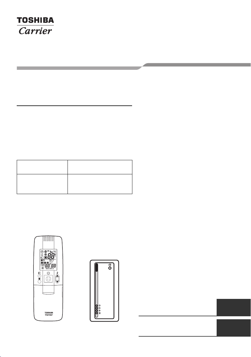
Wireless remote controller
(WX-TA01UES)
Wireless remote controller
and Signal receiving unit
(Wireless remote controller
model name)
Signal receiving
unit
Installation Manual
Remote controller for air
conditioner
Manuel du proprietaire
Télécommande pour climatiseur
(Type split) 15
(Split type) 1
English
Français
Page 2

Wireless remote controller kit
Thank you very much for purchasing TOSHIBA/Carrier Remote Controller for Air
Conditioner.
Please read the owner's manual carefully before using your Remote Controller for Air
Conditioner.
• Be sure to obtain the “Owner’s manual” and “Installation manual” from constructor (or
dealer).
Request to constructor or dealer
• Please clearly explain the contents of the Owner’s manual and hand over it.
Installation Manual
Contents
1 ACCESSORY PARTS . . . . . . . . . . . . . . . . . . . . . . . . . . . . . . . . . . . 2
2 SWITCH LOCATION OF SIGNAL RECEIVING UNIT . . . . . . . . . . 3
3 INSTALLATION LOCATION OF SIGNAL RECEIVING UNIT . . . . 4
4 HOW TO INSTALL THE SIGNAL RECEIVING UNIT . . . . . . . . . . . 5
1-EN
HOW TO PERFORM CABLING OF THE SIGNAL RECEIVING UNIT
5
. . . 8
6 REQUIREMENT . . . . . . . . . . . . . . . . . . . . . . . . . . . . . . . . . . . . . . . 9
7 HOW TO SET THE ROOM TEMPERATURE SENSOR . . . . . . . . 10
8 HOW TO SET THE ADDRESS SWITCH . . . . . . . . . . . . . . . . . . . 11
9 SLIDE SWITCH . . . . . . . . . . . . . . . . . . . . . . . . . . . . . . . . . . . . . . . 11
10 SELF-DIAGNOSIS TABLE AND MEASURES . . . . . . . . . . . . . . . 12
CAUTIONS FOR INSTALLATION OF THE REMOTE CONTROLLER
11
. . 12
12 EXPLANATION TO CUSTOMERS . . . . . . . . . . . . . . . . . . . . . . . . 13
13 HOW TO HANDLE THE REMOTE CONTROLLER . . . . . . . . . . . 13
14 TEST RUN . . . . . . . . . . . . . . . . . . . . . . . . . . . . . . . . . . . . . . . . . . . 14
–1–
Page 3

Wireless remote controller kit
1 ACCESSORY PARTS
No. Parts Quantity
Installation Manual
1
2 Mounting bracket 1
3 Screws ∅0.16” x 1.0” (M4 x 25 mm) 2
4 Screws ∅0.16” x 1.6” (M4 x 40 mm) 2
5 Wood screws 2
6 Spacer 4
7 Wire joints 2
8 Cable tie 1
9
10 Remote controller 1
Signal receiving unit
(provided 7.9” (200 mm) power cable)
Pattern template
3.7” x 2” (95 mm x 51 mm)
1
1
11 Remote cotroller holder 1
12
13 Installation manual 1
14 Owner’s manual 1
Truss tapping screw,
∅0.16” x 0.63” (M4 x 16 mm)
–2–
2
EN
2-EN
Page 4
Wireless remote controller kit
Installation Manual
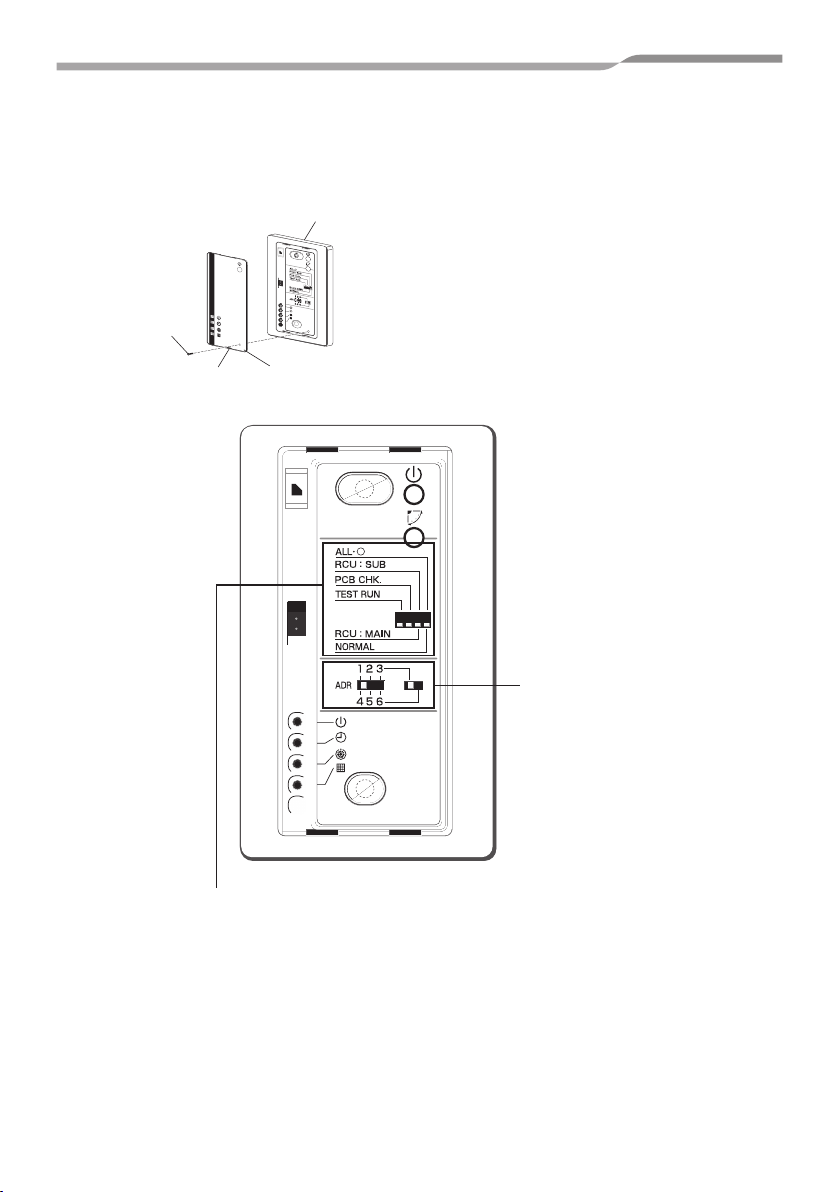
2 SWITCH LOCATION OF SIGNAL RECEIVING
UNIT
Signal receiving unit
1
2
3
4
5
6
Screw
Remove
x{/NORMAL selector switch
All
Set this switch to the “NORMAL” position for the normal operation of the air conditioner. When this switch is set to the
“All
x{” position, the indoor unit of the air conditioner is turned off.
RCU:SUB/RCU:MAIN selector switch
Set this switch to the “RCU:MAIN” position for normal operation. Refer to page 9 for setting to the “RCU:SUB” position.
PCB CHK switch
This switch is not used and should be set in the position shown in the figure.
Face plate
Remove the face plate from Signal receiving unit.
Address selector switch
This switch is used to address one of a
maximum of six air conditioners that can
be controlled by the remote controller.
(Refer to page 11.)
TEST RUN switch
This switch is used for test running.
3-EN
–3–
Page 5

Wireless remote controller kit
Installation Manual
3 INSTALLATION LOCATION OF SIGNAL
RECEIVING UNIT
• Do not install in a location where the air contains oil mist, such as in a kitchen or factory.
• Do not install next to a window, or in any other location directly exposed to sunlight and
outside air.
• Do not install nearby devices which can be expected to produce electrical noise, such as
elevators, automatic doors, and industrial sewing machines.
• If the Signal receiving unit is installed near a rapid-start type or inverter-type fluorescent
lamp (a lamp which does not include a glow lamp), it may not be possible to receive the
wireless remote controller signal in some cases. In order to prevent interference from
fluorescent lamps, leave a minimum of 6’7” (2 m) between the Signal receiving unit and
the fluorescent lamps, and install the Signal receiving unit in a location where it can receive
the wireless remote controller signal when the fluorescent lamps are lit.
–4–
EN
4-EN
Page 6

Wireless remote controller kit
Installation Manual
4 HOW TO INSTALL THE SIGNAL RECEIVING
UNIT
NOTE
• To avoid malfunction of the remote controller, do not assemble or run remote control
wiring together with the power cables, and do not enclose them in the same metal
conduit.
• When the power unit induces electrical noise, it is recommended that a noise filter or the
like be installed.
For flush mounting into a wall, install the Signal receiving unit in a metal
switch box (field supply) that has been recessed into the wall in advance.
1. Insert a flathead screwdriver or similar
tool into the notch, and remove the
face plate.
Screw
∅0.16” x 1.0” (M4 x 25 mm)
Signal receiving unit
Spacer
2. Fix the Signal receiving unit with 2
∅0.16” (4 mm) screws provided. Do
not overly tighten, and use the
provided spacers. If the Signal
receiving unit does not fit in the wall,
cut spacers to adjust the clearance.
3. Connect the Signal receiving unit
wiring (2-core cable) with the cables
Screw
Remove
Face plate
1
2
3
4
5
6
extended from the indoor unit.
(Refer to the section on Signal receiving unit wiring.)
Be sure to determine the correct terminal numbers on the indoor unit when wiring the Signal
receiving unit. The remote controller will be damaged if high voltage (such as 208/230 VAC) is
applied.
4. Reattach the face plate.
When using exposed mounting for the Signal receiving unit, install onto
a wall where the Signal receiving unit can be attached.
1. Insert a straight blade screwdriver or similar
tool into the groove on the bottom of the
Signal receiving unit. Pry open with the
screwdriver and remove the lower case.
(Fig. A).
Face plate
5-EN
Fig.A
–5–
Page 7

Wireless remote controller kit
Installation Manual
2. In order to later pass the Signal receiving
unit wiring out through the upper case (thin
part at the top center), use nippers or a
similar tool to cut a notch in the same size as
Notch where Signal
receiving unit cord
passes through top case
0.08”-0.12”
(2–3 mm)
the Signal receiving unit cord (optional).
(Fig. B)
Connector
Fig.B
3. Disconnect the wires that were connected to
the connector at the time of shipment.
4. Fasten the Signal receiving unit cord
(optional) at the position shown in Fig. C,
Signal receiving unit cord
(optional)
Clamp
Wood
screws (2)
using the provided cable tie. Then connect
the cord to the Signal receiving unit
connector.
5. Shape the Signal receiving unit cord as
shown in Fig. C so that it fits at the top inside
the Signal receiving unit, above the PCB.
Then attach the lower case. At this time,
Fig.C
bend the head of the cable tie so that it faces
sideways.
6. Remove the nameplate and use 2 wood screws to attach the Signal receiving unit.
7. Use the provided cord clips to fasten the Signal receiving unit cord to the wall.
8. Reattach the face plate.
Cable tie
Signal receiving
unit cord
(optional)
Signal
receiving unit
1
2
3
4
5
6
If the separate Signal receiving unit is installed on the ceiling, use the
provided ceiling mounting bracket for installation.
1. Insert a screwdriver or similar tool into the notch at the
bottom to remove the Signal receiving unit face plate.
2. Cut a section out of the ceiling along the provided paper
pattern (3.7” x 2” (95 x 51 mm)).
3. Pass the wire through the provided mounting bracket and
insert the bracket into the installation hole. (Fig. D)
Fig.D
–6–
EN
6-EN
Page 8

Wireless remote controller kit
Installation Manual
4. Use bracket parts (A) and (B) to securely grip the ceiling
material. (Fig. E)
5. Connect the Signal receiving unit wire (2-core) to the wire
from the indoor unit. (Refer to “Wiring the Signal receiving
unit.”) Check the terminal number on the indoor unit
before wiring the Signal receiving unit and be sure not to
wire incorrectly. (The unit will be damaged if high voltage,
such as 208/230 VAC, is applied.)
6. Adjust the provided spacers so that they are several
millimeters larger than the thickness of the ceiling
material. Pass the 2 supplied screws (0.16” x 1.6” (M4 x
40 mm)) through the spacers and tighten them enough to
hold the Signal receiving unit in place.
7. Return parts (A) and (B) through the gap between the
ceiling and Signal receiving unit so that they are
contained in the openings. Then tighten the screws.
Do not tighten the screws excessively. This may result in
damage or deformation of the case.
Tighten to the point where the Signal receiving unit can be
moved slightly by hand. (Fig. F)
8. Reattach the face plate.
Part (A)
Part (B)
Fig.E
Fig.F
7-EN
–7–
Page 9

Wireless remote controller kit
Installation Manual
5 HOW TO PERFORM CABLING OF THE
SIGNAL RECEIVING UNIT
Flush Mounting
Connection diagram
Indoor unit remote
controller terminal
board
Wire of Signal receiving
unit (Field procurement)
(AWG20 (0.5 mm
(UL wires rated 300 V)
2
))
Connector
Provided wire joint (WHT 2)
1. Strip the insulation to approximately 0.55” (14 mm) from the ends of the wires to be connected.
2. Twist together the 2 wires and create a crimp connection at the wire joint.
3. If a special crimping tool is not used, or if the connection is soldered, insulate the wires using
insulation tape.
Wire of Signal
receiving unit
(Field procurement)
Signal receiving unit
Power wire from
Signal receiving unit
Power wire from
Signal receiving
unit
Exposed Mounting
• Connection diagram
Indoor unit remote
controller terminal
board
Wire joint
(provided)
Remote controller cord (optional)
–8–
Signal receiving unit
EN
8-EN
Page 10

Wireless remote controller kit
Installation Manual
6 REQUIREMENT
The control by two remote controllers is enabled by installing the wireless remote controller
with the wired remote controller for an indoor unit.
(Max. 2 remote controllers of wireless or wired are insatiable.)
“2-remote controllers” controlling means that one or multiple units are operated by the
multiple remote controllers.
NOTE
1. Upon confirmation of the terminal numbers of the indoor unit, connect the remote
controller cables without miscabling. (If applied AC 208/230 Volt, damage the unit.)
2. The multiple wireless remote controller kits cannot concurrently be used for an indoor
unit.
3. When installing simultaneously the wireless remote controller with the wired remote
controller, set one of them as the sub remote controller.
• When setting the wired remote controller as the sub, exchange the address connector
at the rear of P.C. board of wired remote controller from master to sub remote
controller.
• When setting the wireless remote controller as the sub, turn the switch of wireless
remote controller Signal receiving unit from RCU: MAIN to RCU:SUB.
To operate an indoor unit by 2 remote controllers
The indoor unit is operated if either wireless or wired remote controller is set as MAIN or SUB
remote controller.
(Total cable length: Within 1312’4” (400 m))
9-EN
Wireless remote
controller kit
Signal receiving unit
Terminal block for
remote controller
cable
Earth
–9–
Wired remote
controller (SUB)
(Sold separately)
Remote controller cable
(Procured locally)
(AWG20 (0.5 mm
(UL wires rated 300 V)
Indoor unit
2
))
Page 11

Wireless remote controller kit
Installation Manual
To operate a group control of multiple indoor units by 2 remote
controllers
MAIN and SUB remote controllers are operable even if they are installed to any indoor unit.
(Total cable length: Within 656’2” (200 m))
Wireless remote
controller kit
Signal receiving unit
Terminal block for
remote controller
cable
Ground
Indoor unit
No.1
Remote controller inter-unit
cable for group control
(Field procurement)
(AWG20 (0.5 mm
(UL wires rated 300 V)
Indoor unit
No.2
Ground
Ground
2
))
Indoor unit
No.3
Wired remote
controller (SUB)
(Sold separately)
Indoor unit
No.4
Ground
7 HOW TO SET THE ROOM TEMPERATURE
SENSOR
• The room temperature sensors are equipped in the indoor unit and the wireless remote
controller.
One of two sensors works.
• The room temperature sensor is set to the indoor unit side as factory default.
To select the sensor in the remote controller, push the SENSOR button (figure below)
inside of the remote controller cover and check “ ” disappears from LCD.
NOTE
If the room temperature data from the remote controller
is not transmitted to the unit for 10 minutes or more, the
sensor at indoor unit side is automatically selected
even if the sensor at the remote controller side is
selected.
Fix the remote controller toward the unit as possible.
SENSOR button
–10–
EN
10-EN
Page 12

Wireless remote controller kit
Installation Manual
8 HOW TO SET THE ADDRESS SWITCH
• When the multiple Signal receiving units are installed in the same room, an address can
be set to prevent cross communication.
• When replacing the battery and pushing ACL button, the address of the remote controller
becomes [ALL] and the Signal receiving unit is enabled to receive signal regardless of
setting of address switch of the operation section.
• For selecting of the remote controller address, refer to Owner’s Manual.
• Change the address of the Signal receiving unit by removing screws of P.C. board cover
of the Signal receiving unit. After then, fix the cover with screws using a clamp.
Display of remote
controller address
Address switch position
of Signal receiving unit
Address Address Address
Address switch
of Signal
receiving unit
can be set any
position.
The address switch is inside the cover of Signal receiving
unit.
Contact the dealer for setting of the switch.
Turn the switch to left for 1, 2 and 3, and right for 4, 5
A
and 6.
Screw
Address
1
4
A
2
3
5
6
Remove
9 SLIDE SWITCH
• Check the slide switch in the battery box of the remote controller is set to [S] / [A] as factory
default.
Select of operation mode set to A.
Slide
switch
position
Select of louver indication set to S.
11-EN
–11–
Face plate
Page 13

Wireless remote controller kit
Installation Manual
10 SELF-DIAGNOSIS TABLE AND MEASURES
Lamp indication of Signal receiving unit
: Goes off
: Blink
(0.5-sec. interval)
Lamp indication Cause Measures
No indication even if the
remote controller is
operated.
Blinks alternatively
Power supply is not turned on.
Miscabling between Signal receiving unit
and indoor unit
Defective connection between Signal
receiving unit and indoor unit
Miscabling or defective connection between
indoor and outdoor units.
Protective device of outdoor unit works. Check outdoor unit.
Protective device of indoor unit works. Check indoor unit.
Check cable
connection and correct it.
Blinks alternatively
11 CAUTIONS FOR INSTALLATION OF THE
REMOTE CONTROLLER
• To operate the remote controller by fixing it to the wall, etc. with a remote controller holder,
turn on the fluorescent lamp, operate the remote controller at the position to be fixed,
check the air conditioner normally operates, and then mount it.
• When the room temperature is sensed by the remote controller, mount the remote
controller paying attention to the following items.
• Place not exposed directly to cold or hot wind.
• Place not exposed directly to the sunlight.
• Other places where the remote controller is not influenced.
–12–
EN
12-EN
Page 14

Wireless remote controller kit
Installation Manual
12 EXPLANATION TO CUSTOMERS
• Hand over the “Owner’s Manual” and “Installation Manuals” to the customer after
installation works.
• Explain usage and maintenance of the remote controller according to “Owner’s Manual”.
13 HOW TO HANDLE THE REMOTE
CONTROLLER
In case using remote controller mounting to the wall, etc.
Check a signal is received correctly by
pushing button at the position to be fixed.
Replacement of battery
1. Holding the both ends of the cover and
remove it by sliding downward.
2. Correctly insert 2 AAA alkali batteries
matching (+) and (-) polarities with
indications.
3. Push ACL button with something tipped and
attach the cover.
Mounting screw Truss
tapping
Ø0.16” x 0.63” (M4 x 16mm)
Put on.
Push.
• To take off remote controller,
pull it toward you.
Cover
ACL button
13-EN
–13–
Page 15

Wireless remote controller kit
Installation Manual
14 TEST RUN
Before test run
• Before turning on the power supply switch, carry out the following procedure.
1 Using 500V-megger, check 1MΩ or more exists between the terminal block 1 to 3 and the earth.
If 1MΩ or less is detected, do not run the unit. Do not apply to the remote controller circuit.
2 Check the valve of the outdoor unit being opened fully.
• To protect the compressor at activation time, leave power-ON for 12 hours or more be for
operating.
How to conduct a TEST RUN
1. Remove the face plate from the Signal receiving unit.
Set the “TEST RUN” switch to the “TEST RUN” position.
2. Push the button on the wireless remote controller to start the
operation of the air conditioner.
The , , and lamps each light under test running.
The temperature cannot be set by the wireless remote
controller with the “TEST RUN” switch is set to the “TEST RUN”
position.
3. Operate the air conditioner in the “heating”, “cooling”, or “fan
only” mode during test running.
The outdoor unit will not operate for approximately 3 minutes
after the air conditioner has been turned on or off.
CAUTION
Do not set the switch to the “TEST RUN” position other than for test running.
The air conditioner may be damaged if this switch is set to the “TEST RUN” position for
normal operation.
(The Signal receiving unit automatically turns off the air conditioner 60 minutes after the
switch has been set to the “TEST RUN” position to prevent continuous test running.)
–14–
EN
14-EN
Page 16

85464369216000
(EH99677601)
 Loading...