

Toshiba SD-P2800SN Service Manual
SERVICE MANUAL
DOCUMENT CREATED IN JAPAN, NOVEMBER, 2005
PORTABLE DVD PLAYER
SD-P2800SN
FILE No. 810-200587
REVISED: 01
Nov.,2005(SH)
LASERBEAMCAUTIONLABEL
Whenthepowersupplyisbeingturnedon,youmaynotremovethislasercautionslabel.Ifitis removed,radiationoflaser
maybereceived.
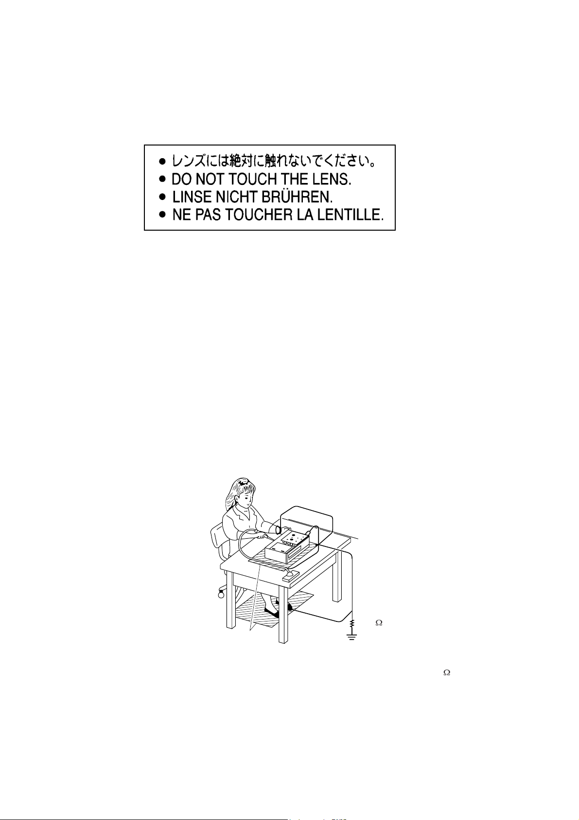
PREPARATIONOFSERVICING
PickupHeadconsistsofalaserdiodethatisverysusceptibletoexternalstaticelectricity.
Althoughitoperatesproperlyafterreplacement,ifitwassubjecttoelectrostaticdischargeduringreplacement,
thelifeof products mightbeshortened.Whenreplacing,useaconductivemat,solderingironwithgroundwire,etc.
to keepthelaserdiodeaway fromthe damagebystaticelectricity.
The above caution is also applied toLSIandIC.
Groundconductive
wriststrapforbody.
Solderingiron
withgroundwire
orceramictype
1M
Conductivemat
Thegroundresistance
betweenthegroundline
andthegroundislessthan10
SAFTY NOTICE
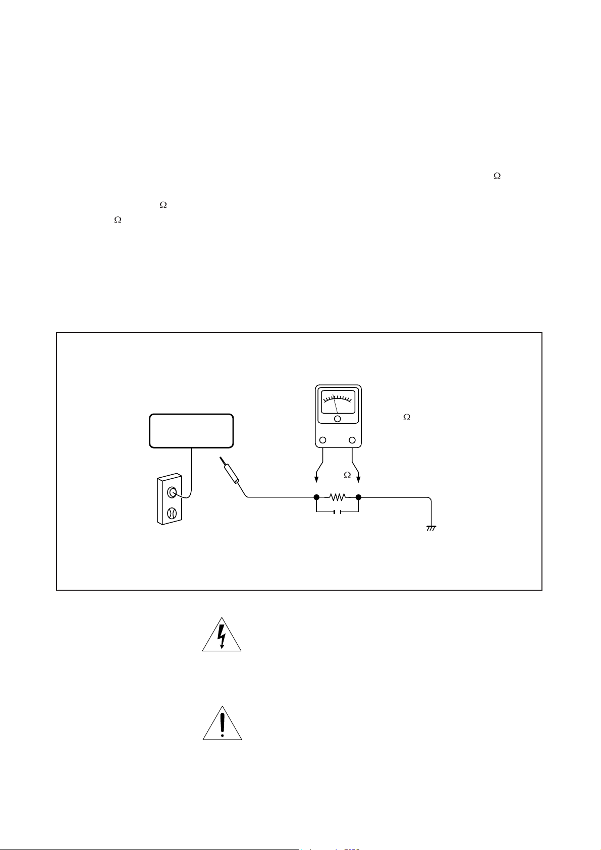
LEAKAGE CURRENT CHECK
SAFTY PRECAUTIONS
Plug the AC line cord directly into a 120V AC outlet (do
not use an isolation transformer for this check). Use an
AC voltmeter, having 5000 per volt or more sensitivity.
Connect a 1500 10W resistor,paralleled by a 0.15uF
150V AC capacitor between a known good earth ground
(water pipe, conduit, etc.) and all exposed metal parts of
cabinet (antennas, handle bracket, metal cabinet
screwheads, metal overlays, control shafts, etc.).
READING SHOULD NOT EXCEED 0.3V
DVD VIDEO PLAYER
Measure the AC voltage across the 1500 resistor.
The test must be conducted with the AC switch on and
then repeated with the AC switch off. The AC voltage
indicated by the meter may not exceed 0.3V.A reading
exceeding 0.3V indicates that a dangerous potential
exists, the fault must be located and corrected.
Repeat the above test with the DVD VIDEO PLAYER
power plug reversed.
NEVER RETURN A DVD VIDEO PLAYER TO THE
CUSTOMER WITHOUT TAKING NECESSARY
CORRECTIVE ACTION.
AC VOLTMETER
(5000 per volt
or more sensitivity)
Good earth ground
1500
10W
such as a water pipe,
conduit, etc.
AC OUTLET
0.15uF 150V AC
Test all exposed metal.
Voltmeter Hook-up for Leakage Current Check
The lightning flash with arrowhead symbol, within an
equilateral triangle, is intended to alert the user to the
presence of uninsulated "dangerous voltage" within the
product's enclosure that may be of sufficient magnitude to
constitute a risk of electric shock to persons.
The exclamation point within an equilateral triangle is
intended to alert the user to the presence of important
operating and maintenance (servicing) instructions in the
literature accompanying the appliance.
1
NC
2
LDVCC
3
VC
4
GND
5
F
6
E
7
CD/DVD SW
8
RF
9
C
10
D
11
B
12
A
13
CDMD
14
DVDMD
15
NC
16
CDLD
17
GND
18
DVDLD
19
NC
20
RFA5V
21
FCS-
22
TRK+
23
TRK-
24
FCS+
1
2
3
4
5
6
MECHANISM
1
OTHER 5V
2
GND
3
POWER SW
4
GND
5
KEY1
6
KEY2
7
KEY3
8
KEY4
9
KEY5
10
KEY6
FUNCTION
BUTTON PCB
SPSP+
SL+
SLGND
LIMIT
1
2
3
4
5
6
7
8
9
10
11
12
13
14
15
16
17
18
19
20
21
22
23
24
1
2
3
4
5
6
1
2
3
4
5
6
7
8
9
10
XS403
XS402
JS201
MAIN PCB
Note: disconnect Inverter Harness
with marking. It may be damage
LCD if it is not connected correctly
to
XS3
JX100
JX101
JX102
1
2
3
4
1
2
3
4
5
6
7
8
9
10
11
12
13
14
15
1
2
3
4
5
6
7
8
9
10
11
12
13
14
15
1
2
3
4
5
6
7
8
9
10
11
12
13
14
15
BATTERY
TM
GND
GND
HV
HV
HV
BRI
TFT on/off
GND
GND
GND
R+
RL+
LGND
GND
GND
GND
R0
R1
R2
R3
R4
R5
GND
G5
G4
G3
G2
G1
G0
GND
VDD
VDD
VDD
GND
GND
DE
GND
DCLK
GND
B0
B1
B2
B3
B4
B5
1
2
3
4
5
6
7
8
9
10
11
12
13
14
15
1
2
3
4
5
6
7
8
9
10
11
12
13
14
15
1
2
3
4
5
6
7
8
9
10
11
12
13
14
15
1
2
3
4
SPEAKER L/R
LCD
XS1
XS5
XS6
BATTERY
R
L
XS3/XS4
XS2
XS7
1
2
3
4
5
6
7
8
9
10
11
12
13
14
15
16
17
18
19
20
21
22
23
24
25
26
27
28
29
30
31
32
33
34
35
36
37
38
39
40
1
2
GND
GND
DCLK
GND
GND
NC
R0
R1
R2
GND
R3
R4
R5
GND
G0
G1
G2
GND
G3
G4
G5
GND
B0
B1
B2
GND
B3
B4
B5
GND
NC
GND
NC
GND
DE
NC
VDD
VDD
VDD
VDD
1
2
1
2
3
4
5
6
7
8
9
10
11
12
13
14
15
16
17
18
19
20
21
22
23
24
25
26
27
28
29
30
31
32
33
34
35
36
37
38
39
40
INVERTER PCB
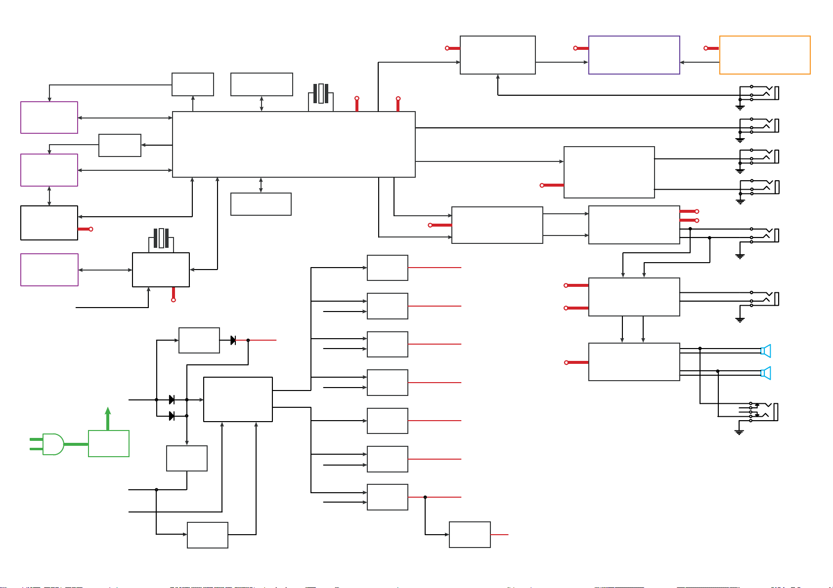
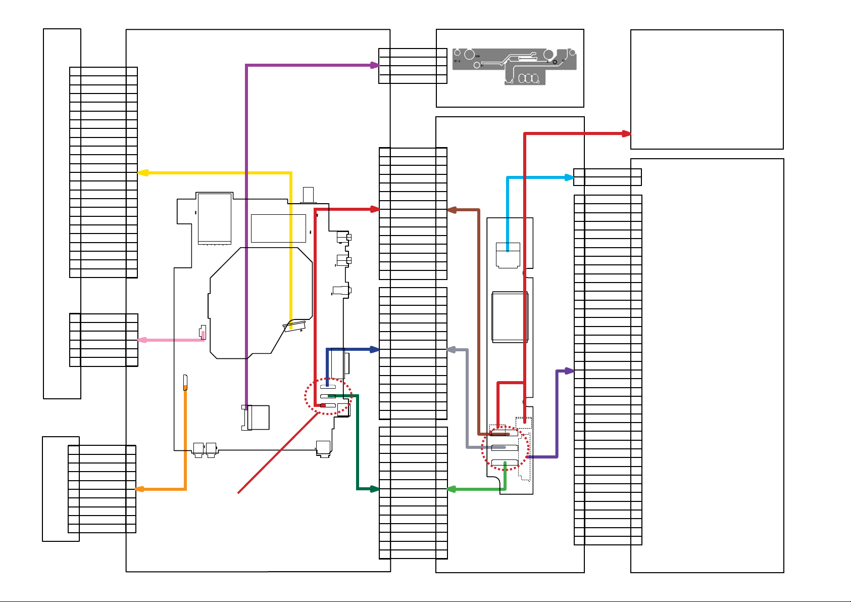
OVERALL BLOCK DIAGRAM
T101 3.3V
UPD5600 (T101)
TFT 3.3V HV
TFT MONITOR
HIGH VOLTAGE ASS’Y
CARD
DV23
PU mechanism
DRIVER
(BA5888)
FUNCTION
BUTTON
RMC IN
110~240V
50/60Hz
74HC4053
DVD 5V
DC IN +12V
AC
Adapter
74HC4053
11.0592MHz
CPU
D1850
CPU 5V
AO4801
ZA3020
64M SDRAM
HY57V641620ETP-H
27MHz
DVD 3.3V
SERVO & DVD PROCESSOR
MPEG-2 DECODER
& VIDEO ENCODER
ZR36882
16M FlashROM
MX29LV160ABTC-70
POWER DVD
HV
POWER ON
5.5V
UPD6100
3.8V
POWER ON
POWER T101
DVD 1.8V
BA05SFP
BA05SFP
BA05SFP
BA05SFP
BA033
PQ033
L
DVD 5V
R
AUDIO D/A
(WM8728)
CPU 5V
DVD 5V
AUDIO 5V
OTHER 5V
TFT 3.3V
UPD6100 3.3V
DVD 5V
OTHER 5V
AUDIO 5V
AUDIO 5V
VIDEO IN
VIDEO OUT
Y/C OUT
BA7660
L
AUDIO AMP
(AZ4558)
R
RL
TC74HC4052
RL
SPEAKER AMP
(TPA0172)
OTHER 5V
AUDIO 5V
D TERMINAL OUT
AUDIO OUT
AUDIO IN
SPEAKER LOUT
SPEAKER ROUT
PHONE OUT
BATTERY
POWER ON
AO4801
8.4V
POWER DVD
PQ033
DVD 3.3V
APS1006
DVD 1.8V

1. Troubleshooting
1. No power when turned on.
2. The initial screen is not displayed on the LCD.
3. The DVD drive does not work.
4. The operation of the DVD player stops at initializing display.
5. Image output stops during the operation.
6. No sound or abnormal sound comes out from the speakers in the DVD player.
7. No image or sound comes out from the external output.
8. No sound comes out from the headphones.
9. No image or sound is output by external input.
10. The DVD drive does not operate with the battery.
1.1 No power w
When the power is turned on, and if the LED on the front panel does not light green, check
the following items and repair the defective parts.
(1) Check the power supply cable
If the cable is not the supplied one, replace it with the supplied cable and turn on the
power again.
If the power supply cable is good, the AC adapter may be defective.
If the LED does not light after replacing, check the following items.
(2) Check the AC adapter
If the AC adapter is not the supplied one, replace it with the supplied AC adapter and
turn on the power.
If the
If the LED does not light after replacing, check the following items.
(3) Check the Power switch
Press the POWER switch on the DVD player. If the power does not turn on, check the
following:
Check the connector of the Function button PCB in the DVD player.
(If the connection is loose, repair the connection.)
Replace the Function button PCB and turn on the power again.
hen turned on.
AC adapter is good, the Main PCB may be defective.
If the LED does not light after replacing, check the following items.

1.2 The initial screen is not displayed on the LCD.
If the initial screen is not displayed on the LCD, check the following items.
(1) Check the LED on the front
If the LED does not light, proceed to 1.1.
(2) Check the backlight
If the backlight does not light up, separate the DVD player into top assembly and
bottom assembly, and check the connector harness, and check the connectors for
defects.
If the connector harness is broken:
Replace the broken harness.
If the connector harness is not broken:
Remove the LCD cover and plate of the LCD unit and check the following:
Check the connector of the FL harness, replace the FL inverter or the LCD.
If the connectors are good, replace the FL inverter or the LCD.
(3) Check the lighting of LCD
If the LCD does not light, separate the DVD player into the top assembly and bottom
assembly, and check the LCD harness, and check the connectors on the main board.
If the connector is broken:
Replace the LCD harness or the main board.
If the connector is not broken:
Remove the LCD cover and plate of the LCD unit, and check the connection to the
harness of the LCD unit.
If a bad connection is found.
Connect the LCD harness to the LCD unit.
Other than the above
Replace the LCD unit or the main board.

1.3 The DVD drive does not work.
When the DVD drive does not work after the power is turned on, check the following items
and repair or replace the defective parts.
(1) Press the DISC cover switch and turn on the power. Then check whether or not
the optical pick-up lens of the DVD drive lights.
CAUTION: Visible laser radiation when open and interlock defeated. Do not stare into
Laser beam.
The optical pick-up lens lights dim:
It is caused by deterioration of the optical pick-up lens. Replace the DVD drive.
The optical pick-up lens does not light:
Check the connectors of the DVD-FFC. Also check the connection to the main
board and to the DVD drive.
Loose connection is found.
Repair the connection, and then check the operation of the DVD drive again.
The DVD-FFC is broken.
Replace the DVD drive.
Other than the above.
Replace the DVD drive or the main board.
(2) Insert a DVD disk and turn on the power
The DVD drive does not work:
The motor of the DVD drive or the main board is defective. Replace the DVD drive
or the main board.
The DVD drive works but the initializing operation of the optical pick-up lens
does not start (the optical pick-up lens operates twice), or abnormal noise
sound:
The DVD drive is defective. Replace the DVD drive.
1.4 The operation of the DVD player stops at initializing display.
If the DVD player does not work after the initializing screen is displayed, check the
indication on the screen. Then repair the defect according to it.
(1) Insert a DVD disk and close the DISC cover, and turn on the power. Then check
the LCD screen or use an external display.
The message “loading” is not displayed or the operation stops at the
message “Loading”.
Since the DVD drive or the main board is defective, check in the following order:
1) DVD drive
2) Main board
The message “CHECK DISK” is displayed.
Check the DVD disk for fingerprints, dirt, etc.
If the DVD disk is OK, then check the following items:
1) Check the DVD-FFC
If a loose connection, repair the connection.
If it is damaged, replace the DVD drive.
2) Other than above
For other cases, replace the unit in the following order:
DVD drive (defective optical pick-up)
Main board
 Loading...