

Toshiba SD-P2700-S-TN, SD-P2700-S-TR, SD-P2700-S-TE Service Manual
SERVICE
Feb.,2005
FILE
810-200507
SD-P2700-S-TN
MANUAL (TENTATIVE)
NO.
S
PORTABLE DVD PLAYER
Rev.00
VIDEO/AUDIO
SD-P2700-S-TE
SD-P2700-S-TR
(SD-P2700-S-TN)
Whenthepowersupplyisbeingturnedon,youmaynotremovethislasercaution'slabel.Ifitwas removed,the radiationof
laser maybereceived.
LASERBEAMCAUTIONLABEL
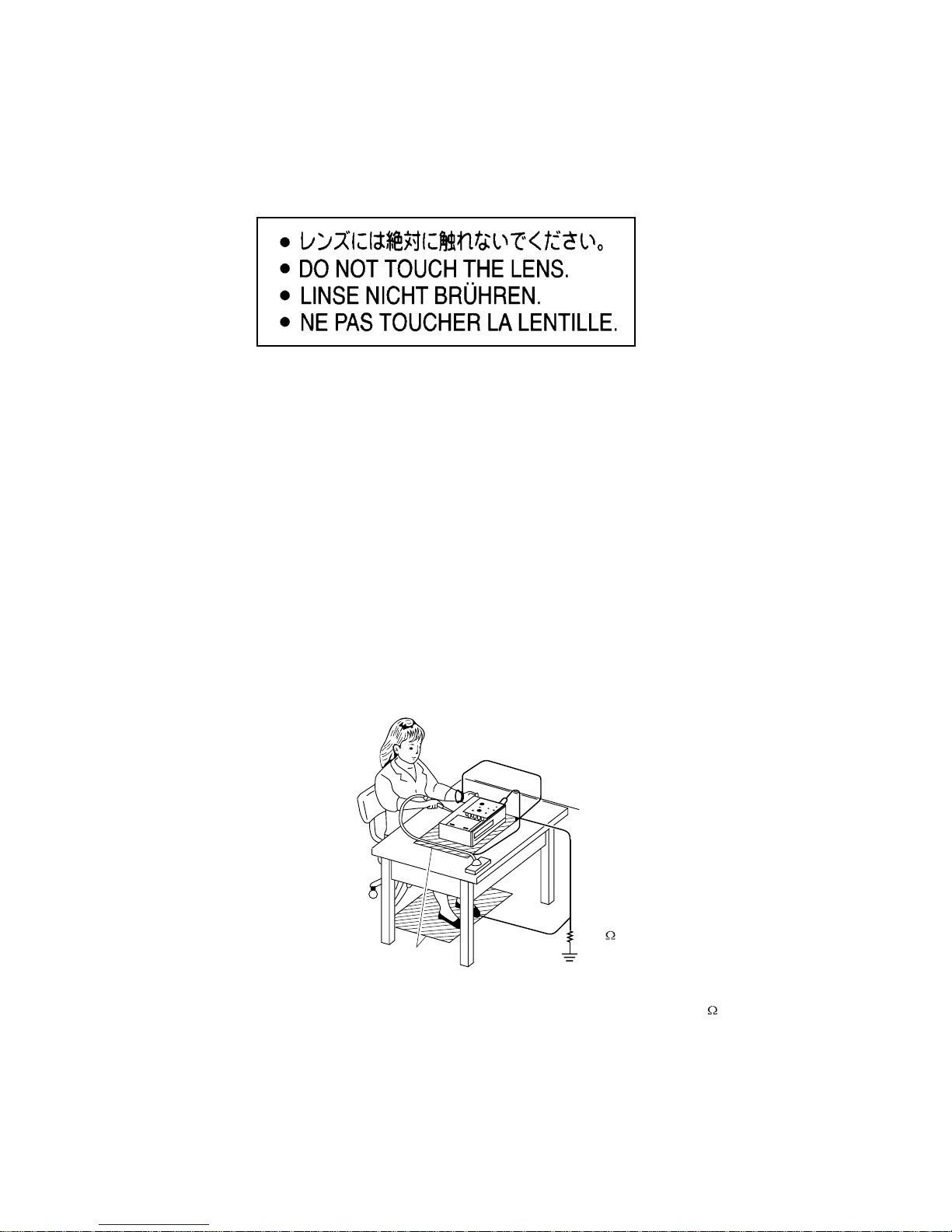
PREPARATIONOFSERVICING
PickupHeadconsistsofalaserdiodethatisverysusceptibletoexternalstaticelectricity.
Althoughitoperatesproperlyafterthe replacement,ifitwassubjecttoelectrostaticdischargeduringreplacement,
thelifeof the product mightbeshortened.Whenreplacing,useaconductivemat,solderingironwithgroundwire,etc.
to keepthelaserdiode awayfromthe damagebystaticelectricity.
The above cautions are also applied to LSI and IC.
Solderingiron
withgroundwire
orceramictype
Groundconductive
wriststrapforbody.
Conductivemat
Thegroundresistance
betweenthegroundline
andthegroundislessthan10
1M
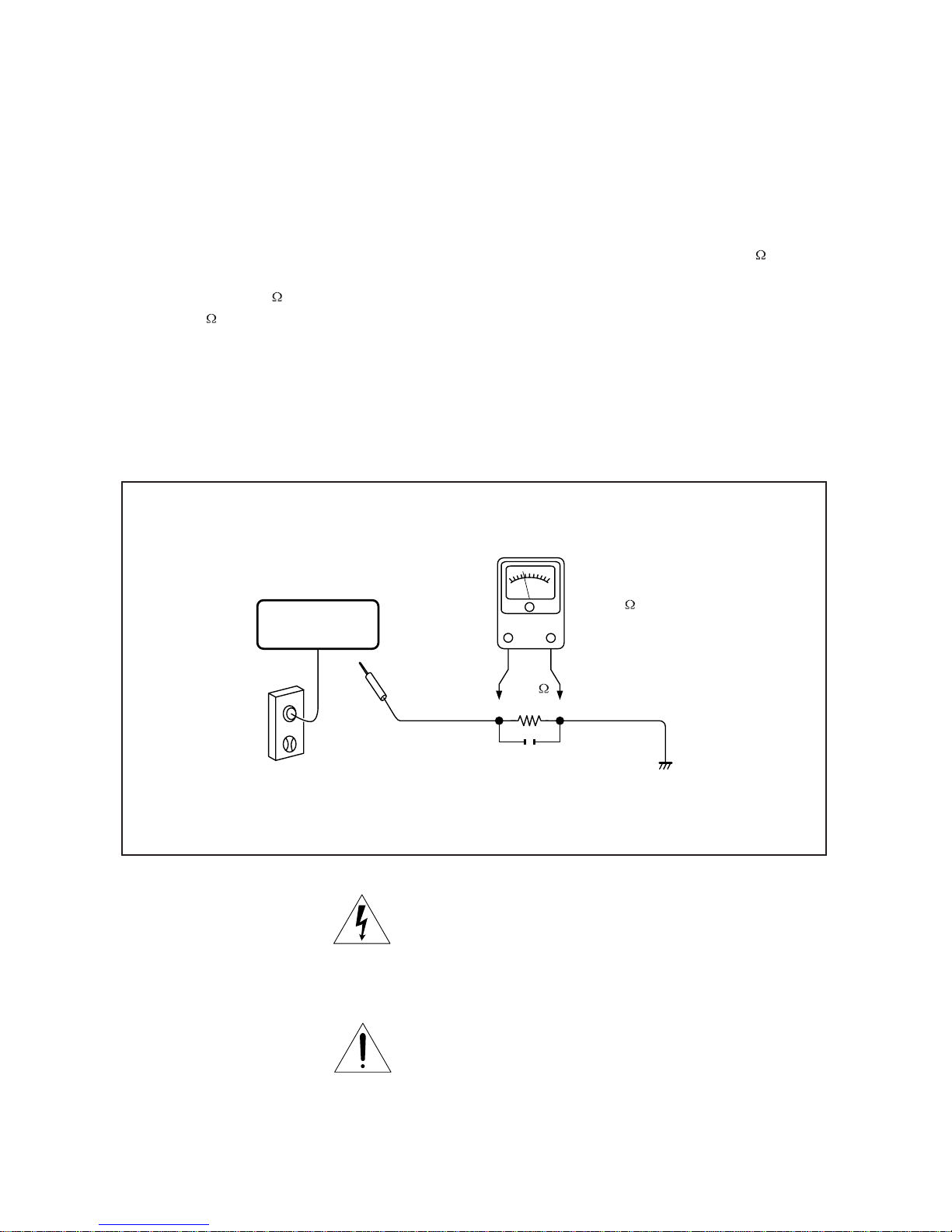
SAFTY NOTICE
Plug the AC line cord directly into 120V AC outlet (do
not use an isolation transformer for this check). Use an
AC voltmeter, having 5000 per volt or more sensitivity.
Connect 1500 10W resistor,paralleled by 0.15uF
150V AC capacitor between a known good earth ground
(water pipe, conduit, etc.) and all exposed metal parts of
cabinet (antennas, handle bracket, metal cabinet
screwheads, metal overlays, control shafts, etc.).
SAFTY PRECAUTIONS
LEAKAGE CURRENT CHECK
Measure the AC voltage across the 1500 resistor.
The test must be conducted with the AC switched on and
then repeated with the AC switched off. The AC voltage
indicated by the meter may not exceed 0.3.
Exceeding 0.3V indicates that a dangerous potential
exists, the fault must corrected.
Repeat the above test with a DVD VIDEO PLAYER
power plug reversed.
NEVER RETURN A DVD VIDEO PLAYER TO THE
CUSTOMER WITHOUT TAKING NECESSARY
CORRECTIVE ACTION.
READING SHOULD NOT EXCEED 0.3V
DVD VIDEO PLAYER
AC OUTLET
AC VOLTMETER
Test all exposed metal.
Voltmeter Hook-up for Leakage Current Check
0.15uF 150V AC
1500
10W
(5000 per volt
or more sensitivity)
Good earth ground
such as a water pipe,
conduit, etc.
The lightning flash with arrowhead symbol, within an
equilateral triangle, is intended to alert the user to the
presence of uninsulated "dangerous voltage" within the
product's enclosure that may be of sufficient magnitude to
constitute a risk of electric shock to persons.
The exclamation point within an equilateral triangle is
intended to alert the user to the presence of important
operating and maintenance (servicing) instructions in the
literature accompanying the appliance.
1234567
8
KEYIN3
KEYIN2
KEYIN1
KEYIN0
KEYOUT0
KEYOUT1
KEYOUT2
KEYOUT3
1234567
8
1
2
3
4
5
6
7
8
9
10
11
12
13
14
15
16
17
18
19
20
21
22
23
24
NC
LDVCC
V20
GND
F
E
CD/DVD SW
RF
C
D
B
A
VRCD
VRDVD
DVDMD
CDLD
GND
DVDLD
NC
AVCC
FCSTRK+
TRKFCS+
1
2
3
4
5
6
7
8
9
10
11
12
13
14
15
16
17
18
19
20
21
22
23
24
1
2
3
4
5
6
1
2
3
4
5
6
SPSP+
SL+
SLGND
LIMIT
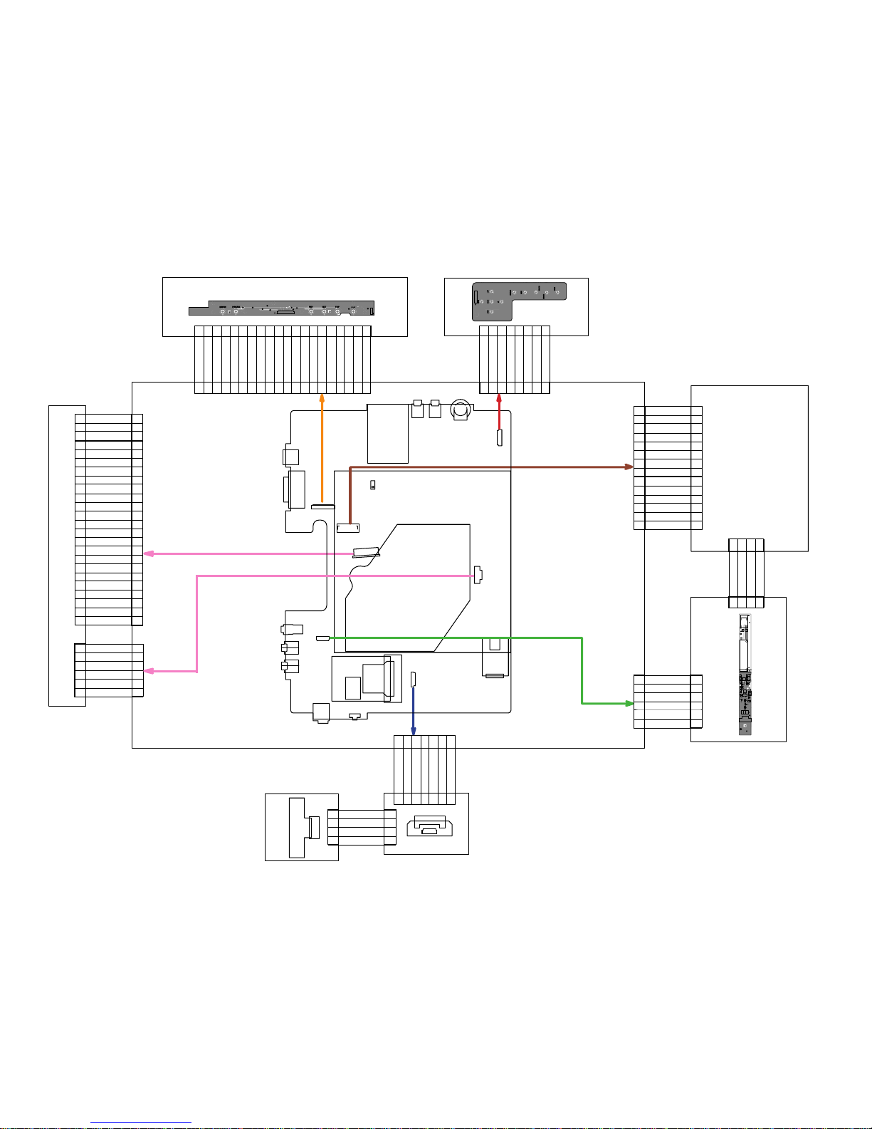
KEY A PCB
MECHANISM
MAIN PCB
HIGH VOLTAGE PCB
TFT LCD
BATTERY PCB
XS01
XS100
XS108
XS401
XS403
XS301
XS106
XS402
SW101JS101
JS501
JS502
JS503
JS504
JS505
JS506
JS507
JS508
SW401
XS101
XS405
VR500
1 2 3 4 5 6 7 8 910111213141516171819
20
LOUT+
LOUT-
GND
ROUT+
ROUT-
GND
GNDIRGND
+P5V
GND
GND
KEYOUT3
KEYOUT2
KEYOUT1
KEYOUT0
KEYIN0
KEYIN1
KEYIN2
KEYIN3
1 2 3 4 5 6 7 8 910111213141516171819
20
KEY B PCB
1
2
3
4
5
6
7
8
9
10
11
12
13
14
PANEL3V3
PANEL3V3
GND
GND
TXOUTTXOUT+
TXOUT1TXOUT1+
TXOUT2TXOUT2+
TXCLKOUTTXCLKOUT+
GND
GND
1
2
3
4
5
6
7
8
9
10
11
12
13
14
1
2
3
4
5
6
1
2
3
4
5
6
HV
HV
TFT OFF
BRIGHT
GND
GND
1 2 3
4
1 2 3
4
NCNCISEN
VSEN
1 2 3 4 5 6 7
1 2 3 4 5 6 7
BATT+
BATT+
BATT+TSGND
GND
GND
1
2
3
4
1
2
3
4
BATT+
TS
GND
GND
BATTERY
PROTECTOR
PCB
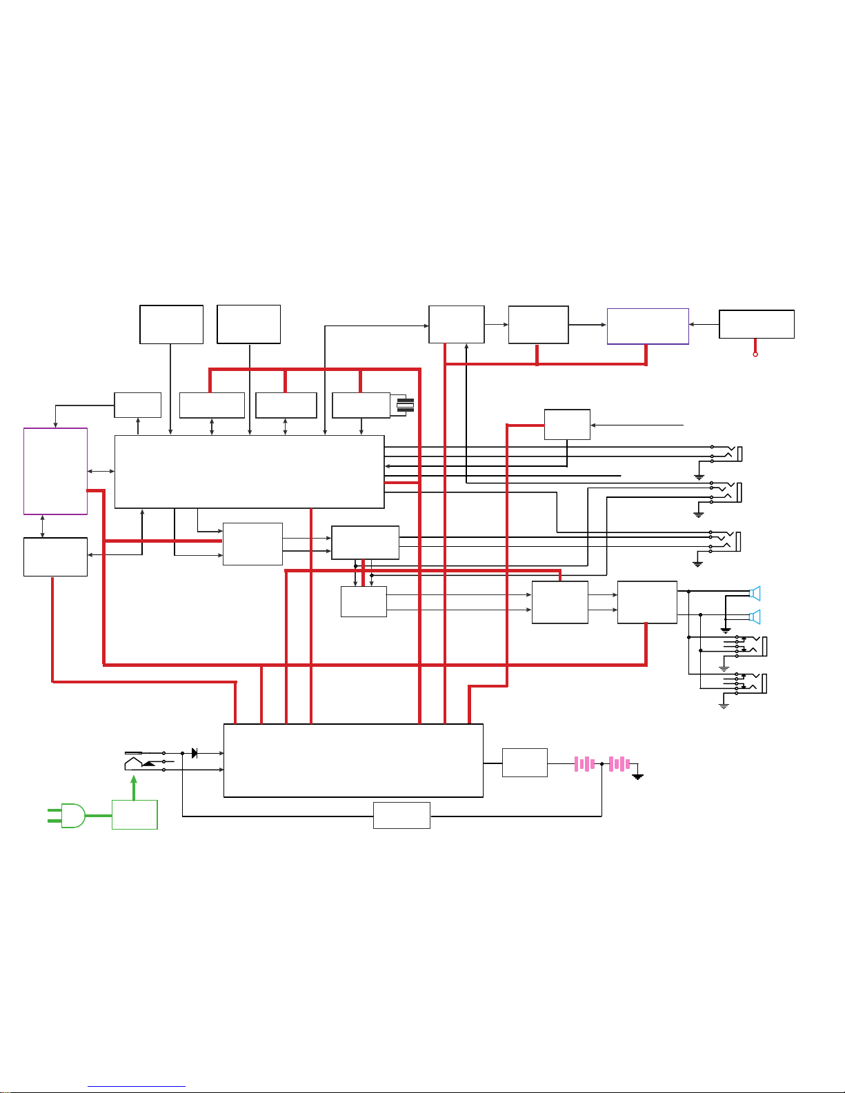
RF AMP & SERVO & DVD PROCESSOR
MPEG-2 DECODER & VIDEO ENCODER
D3800
OVERALL BLOCK DIAGRAM
AC
Adapter
DC IN +12V
DC / DC
UPA1716
110~240V
50/60Hz
BATTERY
DV23(HD80)
PU mechanism
DRIVER
(CMD5954)
16M FlashROM
MX29LV160ABTC-70
64M SDRAM
NT56V6620COT-75S
TC4W53
27MHz
AUDIO D/A
(PCM1742)
TFT MONITOR
AUDIO AMP
(NJM4558)
74HCU04
27MHz
L
R
L
R
DC 12V
OSCILLATOR
OZ9RR
TW8803
TPA6011A4
TL1453/ZA3020/XN4601/IRF7304
BA033/UPC29M05/PQ03EZ11/LM1117
DRVCC
5V
KEY BOARD
SDP2700KA
KEY BOARD
RMC
SDP2700KB
SWITCH
4052
AUDIO AMP
(NJM4558)
SPEAKER LOUT
SPEAKER ROUT
PHONE OUT1
PHONE OUT2
AV OUT
L
R
V
AV IN
V
L
R
S-VIDEO OUT
Y
C
UB6220
D TERMINAL
USB
SD CARD
LVDS
DS90C383
(BQ2057C)
DVD
+5V
AUDIO
+/-5V
DVD
3.3V
DVD
1.8V
TFT
3.3V
SD
3.3V

1. Troubleshooting
1. No power when turned on.
2. The initial screen is not displayed on the LCD.
3. The DVD drive does not work.
4. The operation of the DVD player stops at initializing display.
5. Image output stops during the operation.
6. No sound or abnormal sound comes out from the speakers in the DVD player.
7. No image or sound comes out from the external output.
8. No sound comes out from the headphones.
9. No image or sound is output by external input.
10. The DVD drive does not operate with the battery.
11. SD CARD is not read on the LCD.
1.1 No power when turned on.
When the power is turned on, and if the LED on the front panel does not light green, check
the following items and repair the defective parts.
(1) Check the power supply cable
If the cable is not the supplied one, replace it with the supplied cable and turn on the
power again.
If the power supply cable is good, the AC adapter may be defective.
If the LED does not light after replacing, check the following items.
(2) Check the AC adapter
If the AC adapter is not the supplied one, replace it with the supplied AC adapter and
turn on the power.
If the AC adapter is good, the main board may be defective.
If the LED does not light after replacing, check the following items.
(3) Check the Power switch
Press the POWER switch on the DVD player. If the power does
not turn on, check the following:
zCheck the connector of the switch unit in the DVD player.
(If the connection is loose, repair the connection.)
zReplace the switch unit and turn on the power again.
If the LED does not light after replacing, check the following items.
(4) Replace the main board

1.2 The initial screen is not displayed on the LCD.
If the initial screen is not displayed on the LCD, check the following items.
(1) Check the LED on the front
If the LED does not light, proceed to 1.1.
(2) Check the backlight
If the backlight does not light up, separate the DVD player into the top assembly and
the bottom assembly, and check the connector harness, and check the connectors for
defects.
If the connector harness is broken:
Replace the broken harness.
If the connector harness is not broken:
Remove the LCD cover and the plate of the LCD unit and check the following:
zCheck the connector of the FL harness, repair connectors.
zIf the connectors are good, replace the FL inverter or the LCD.
(3) Check the lighting of LCD
If the LCD does not light, separate the DVD player into the top assembly and bottom
assembly, check the LCD harness, and check the connectors of the main board.
If the connector is broken:
Replace the LCD harness or the main board.
If the connector is not broken:
Remove the LCD cover and plate of the LCD unit, and check the connection to the
harness of the LCD unit.
zIf a bad connection is found.
Connect the LCD harness to the LCD unit.
zOther than the above
Replace the LCD unit or the main board.

1.3 The DVD drive does not work.
When the DVD drive does not work after the power is turned on, check the following items
and repair or replace the defective parts.
(1) Press the DISC cover switch at the cen ter of the DVD player and turn on the
power. Then check whether or not the optical pick-up lens of the DVD drive
lights.
CAUTION: Visible laser radiation may be present when the encloser is opened. Don't stare it.
The optical pick-up lens lights dim:
It is caused by deterioration of the optical pick-up lens. Replace the DVD drive.
The optical pick-up lens does not light:
Check the connectors of the DVD-FFC. Also check the connection to the main
board and to the DVD drive.
zLoose connection is found.
Repair the connection, and then check the operation of the DVD drive again.
zThe DVD-FFC is broken.
Replace the DVD drive.
zOther than the above.
Replace the DVD drive or the main board.
(2) Insert a DVD disk and turn on the power
The DVD drive does not work:
The motor of the DVD drive or the main board is defective. Replace the DVD drive
or the main board.
The DVD drive works but the initializing operation of the optical pick-up lens
does not start (the optical pick-up lens operates twice), or abnormal noise
sound:
The DVD drive is defective. Replace the DVD drive.
1.4 The operation of the DVD player stops at initializing display.
If the DVD player does not work after the initializing screen is displayed, check the
indication on the screen. Then repair the defect according to it.
(1) Insert a DVD disk and clo se the DISC cover, and turn on t he po w er. Then check
the LCD screen or use an external display.
zThe message “loading” is not displayed or the operation stops at the
message “Loading”.
Since the DVD drive or the main board is defective, check in the following order:
1) DVD drive
2) Main board
zThe message “CHECK DISK” is displayed.
Check the DVD disk for fingerprints, dirt, etc.
If the DVD disk is OK, then check the following items:
1) Check the DVD-FFC
If a loose connection, repair the connection.
If it is damaged, replace the DVD drive.
2) Other than above
For other cases, replace the unit in the following order:
zDVD drive (defective optical pick-up)
zMain board
 Loading...