

Page 1
PORTABLE DVD PLAYER
SERVICE MANUAL
SD-P2600
FILE NO. 810-200402
DOCUMENT CREATED IN JAPAN, Apr., 2004
REVISION 1
Page 2
LASERBEAMCAUTIONLABEL
Whenthepowersupplyisbeingturnedon,youmaynotremovethislasercautionslabel.Ifitremoves,radiationoflaser
maybereceived.
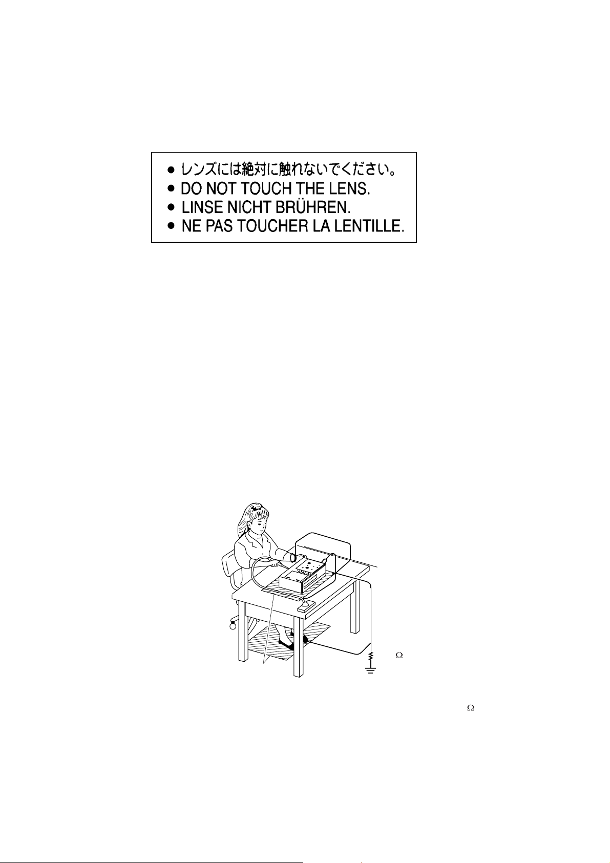
PREPARATIONOFSERVICING
PickupHeadconsistsofalaserdiodethatisverysusceptibletoexternalstaticelectrocity.
Althoughitoperatesproperlyafterreplacement,ifitwassubjecttoelectrostaticdischargeduringreplacement,
itslifemightbeshortened.Whenreplacing,useaconductivemat,solderingironwithgroundwire,etc.to
protectthelaserdiodefromdamagebystaticelectricity.
Andalso,theLSIandICaresameasabove.
Groundconductive
wriststrapforbody.
Solderingiron
withgroundwire
orceramictype
1M
Conductivemat
Thegroundresistance
betweenthegroundline
andthegroundislessthan10
Page 3
SAFTY NOTICE
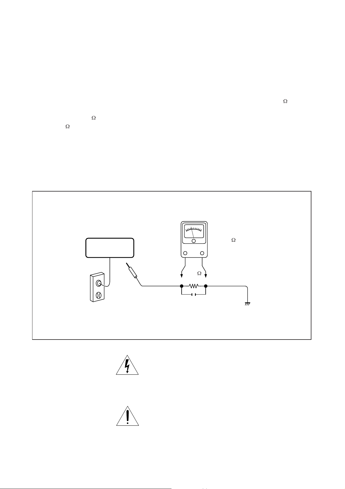
LEAKAGE CURRENT CHECK
SAFTY PRECAUTIONS
Plug the AC line cord directly into a 120V AC outlet (do
not use an isolation transformer for this check). Use an
AC voltmeter, having 5000 per volt or more sensitivity.
Connect a 1500 10W resistor,paralleled by a 0.15uF
150V AC capacitor between a known good earth ground
(water pipe, conduit, etc.) and all exposed metal parts of
cabinet (antennas, handle bracket, metal cabinet
screwheads, metal overlays, control shafts, etc.).
READING SHOULD NOT EXCEED 0.3V
DVD VIDEO PLAYER
Measure the AC voltage across the 1500 resistor.
The test must be conducted with the AC switch on and
then repeated with the AC switch off. The AC voltage
indicated by the meter may not exceed 0.3V.A reading
exceeding 0.3V indicates that a dangerous potential
exists, the fault must be located and corrected.
Repeat the above test with the DVD VIDEO PLAYER
power plug reversed.
NEVER RETURN A DVD VIDEO PLAYER TO THE
CUSTOMER WITHOUT TAKING NECESSARY
CORRECTIVE ACTION.
AC VOLTMETER
(5000 per volt
or more sensitivity)
Good earth ground
1500
10W
such as a water pipe,
conduit, etc.
AC OUTLET
0.15uF 150V AC
Test all exposed metal.
Voltmeter Hook-up for Leakage Current Check
The lightning flash with arrowhead symbol, within an
equilateral triangle, is intended to alert the user to the
presence of uninsulated "dangerous voltage" within the
product's enclosure that may be of sufficient magnitude to
constitute a risk of electric shock to persons.
The exclamation point within an equilateral triangle is
intended to alert the user to the presence of important
operating and maintenance (servicing) instructions in the
literature accompanying the appliance.
Page 4

1. Troubleshooting
1. No power when turned on
2. The initial screen is not displayed on the LCD
3. The DVD drive does not work
4. The operation of the DVD player stops at initializing display
5. Image output stops during the operation
6. No sound or abnormal sound comes out from the speakers in the DVD player
7. No image or sound comes out from the external output
8. No sound comes out from the headphones
9. No image or sound is output by external input
10. The DVD drive do es not operate with the battery
11. The SD card or Multimedia Card is not read correctly
1.1 No power when turned on
When the power is not turned on (front panel indicator does not light green) after pressing the
POWER button or the PLAY button, check the following items and repair the defective parts.
(1) Check the power supply cable
If the cable is not the supplied one, replace it with the supplied cable and turn on the power
again.
If the LED does not light after replacing, check the following items.
(If a cable other than the supplied one is used, the AC adapter may be damaged.)
(2) Check the AC adapter
If the AC adapter is not the supplied one, replace it with the supplied AC adapter and turn on
the power again.
If the LED does not light after replacing, check the following items.
(If an AC adapter other than the supplied one is used, the power board may be damaged.)
(3) Check the switch buttons
Check the following items.
a) Chec k the connector of the switch in the DVD player.
(If the connection is loose, reconnect the connector firmly.)
b) Repl ace the cover and turn on the power again.
(If the LED does not light after replacing, check the following items.)
(4) Check the power supply harness (MH95)
Check the connection of the 4-pin harness between the power IF board and the main board.
If the harness is not soldered fully, mount solder on it again. Then turn on the power again.
If the LED does not light after replacing, check the following items.
(5) Replace the power supply IF board
Check the soldered connection for the AC adapter jack. If a bad or poor solder connection is
found, replace the power supply IF board or PJ801. (The connector, which is on the power
board.)
If the LED does not light after replacing, check the following items.
(6) Replace the fuse
Replace F801 and F802 on the main board.
If the LED does not light after replacing, check the following items.
(7) Other than the above
Replace the main board.
(Replace the main board, for the trouble could be due to the damage on the main board.)
After replacing the main board, special adjustments in TOSHIBA are required. If not, readout of
DVD or CD media might not function properly.
Page 5

1.2 The initial screen is not displayed on the LCD
If the initial screen is not displayed on the LCD, check the following items.
(1) Check the LED on the front
If the LED does not light, refer to 1.1.
(2) Check the back light
If the back light does not light up, separate the DVD player into the top assembly and bottom
assembly, and check the inverter harness MH94 (Check whether or not the connector side is
broken.), and check the connectors for defects.
a) If the connector harness is broken :
Replace the broken harness.
b) If the connector harness is not broken :
Remove the LCD cover and plate of the LCD unit and check the following.
• If the FL inverter harness is not inserted completely or disconnected, reconnect the
harness properly.
• Other than the above:
Replace the FL inverter or the LCD.
(3) Check the lighting of LCD
If the LCD does not light, separate the DVD player into the top assembly and bottom assembly,
and check the LCD harness MH96 (Check whether or not the connector side is broken.), and
check the connectors on the main board.
a) If the connector is broken :
Replace the LCD harness or the main board.
b) If the connector is not broken :
Remove the LCD cover and plate of the LCD unit and check the following items.
c) Check the connector of the LCD harness connected to the LCD module (for check of
insertion with slant or others).
If the LCD harness is not inserted completely or disconnected, reconnect the harness
properly.
d) Other than the above:
Replace the LCD module or the main board.
1.3 The DVD drive does not work
When the DVD drive does not work after the power is turned on, check the following items and
repair or replace the defective parts.
(1) Press the DISK cover switch (S102) at the center of the DVD player and turn on the
power. Then check whet her or not the optical pick-up lens of the DVD drive light.
< CAUTION >
Do not stare in visible laser radiation at close when checking the optical pick-up lens.
• The optical pick-up lens lights dim :
It is caused by deterioration of the optical pick-up lens. Replace the DVD drive.
• The optical pick-up lens does not light :
Check the connection of the DVD-FFC to the main board and to the DVD drive.
Repair the connections and check the operation of the DVD drive again.
(2) Check whether or not the DVD-FFC is broken.
(If the DVD-FFC is broken, replace it.)
(3) Other than the above
Replace the DVD drive or the main board. [Perform pick short of the DVD drive when
replacing.]
After replacing the DVD drive or the main board, special adjustments in TOSHIBA are
required. If not, readout of DVD or CD media might not function properly.
Insert a DVD disk and turn on the power. Check whether or not the DVD drive works.
• The DVD drive does not work.
Adjust the DVD drive. If the drive does not work after the adjustment, the motor portion
of the DVD drive or the main board is defective. Replace it. After replacing the DVD
drive or the main board, special adjustments in TOSHIBA are required. If not, readout of
DVD or CD media might not function properly.
Page 6

• After the adjustment, the DVD drive works but the initial operation of pick-up (two pick-
ups) is not performed, or abnormal sound comes out, the DVD drive is defective.
Replace the DVD drive. After replacing the DVD drive, special adjustments in TOSHIBA
are required. If not, readout of DVD or CD media might not function properly.
1.4 The operation of the DVD player stops at initializing display
If the DVD does not work after the initializing screen is displayed, check the indication on the
screen. Then repair the defect according to it.
(1) Insert a DVD disk, and turn on the power. Then check the LCD screen or use an external
display.
The message “Loading” is not displayed or the operation stop s at the message
“Loading”.
Since the DVD drive or the main board is defective, replace it in the following order and check
the operation. [Perform pick short of the DVD drive when replacing.]
1) Replace the DVD drive
2) Replace the main board
After replacing the DVD drive or the main board, special adjustments in TOSHIBA are
required. If not, readout of DVD or CD media might not function properly.
The message “PLEASE CHECK DISK” is displayed.
Check the DVD disk for fingerprints, dirt etc.
If the DVD disk has no problem, then check the following items.
1) Check the DVD-FFC
If connections are loose, reconnect the DVD-FFC firmly.
If the DVD-FFC is damaged, replace it with new one.
2) Other than the above
For other cases, replace the unit in the following order.
[Perform pick short of the DVD drive when replacing.]
• Replace the DVD drive (for defective optical pick-up)
• Replace the main board (for defective FFC connector)
After replacing the DVD drive or the main board, special adjustments in TOSHIBA are
required. If not, readout of DVD or CD media might not function properly.
1.5 Image output stops during the operation
If the image output from the media in the DVD player stops during operation, replace the DVD
drive. [Perform pick short of the DVD drive when replacing.]
After replacing the DVD drive, special adjustments in TOSHIBA are required. If not, readout of DVD
or CD media might not function properly.
1.6 No sound or abnormal sound comes out from the speakers in the DVD player
If no sound comes out from the speakers in the DVD players, check the following items.
(1) Check for moving images on the LCD screen
Check whether or not the move of image stops in halfway. If it stops, replace the DVD drive.
[Perform pick short of the DVD drive when replacing.]
After replacing the DVD drive, special adjustments in TOSHIBA are required. If not, readout of
DVD or CD media might not function properly.
(2) Check the operation of the DVD drive
Check whether or not the DVD drive works. If it stops, replace the DVD drive.
[Perform pick short of the DVD drive when replacing.]
After replacing the DVD drive, special adjustments in TOSHIBA are required. If not, readout of
DVD or CD media might not function properly.
Page 7

(3) Check the connection of the speakers in the LCD module
Separate the DVD player into the top assembly and bottom assembly, and then check the
connection of the speaker harness to the main board. If the connection is loose, reconnect it
firmly.
Other than the above, disassemble the LCD unit and replace the speakers or the main board.
After replacing the main board, special adjustments in TOSHIBA are required. If not, readout of
DVD or CD media might not function properly.
1.7 No image or sound comes out from the external output
If any image or sound is not output from the TV connected by the external output cable, replace the
main board or the connector (PJ701, PJ703, PJ704, PJ705 and PJ709.) When replacing PJ705,
cut the connector end on the back of the board within 1mm after soldering.
After replacing the main board, special adjustments in TOSHIBA are required. If not, readout of
DVD or CD media might not function properly.
< NOTE > Before this test, make sure the DVD drive works properly.
1.8 No sound comes out from the headphones
If no sound comes out from the headphones, replace the main board or the connector (PJ702,
PJ706.)
1.9 No image or sound comes out from external input
If any image or sound from external input is not output, replace the main board or the connector
(PJ709.)
1.10 The DVD drive does not operate with the battery
(1) Check the operation with the verified battery
Install a verified battery and make sure the LED lights up orange while the AC adapter is
connected. When the LED does not light up or blink, check the connection of the battery
connector harnesses inside the DVD player. If the connection is loose, reconnect it firmly. If
the harness has been connected firmly, replace the main board.
After replacing the main board, special adjustments in TOSHIBA are required. If not, readout
of DVD or CD media might not function properly.
(2) Other than the above, replace the battery
< NOTE >
For this check, use a battery, which is not fully charged (because the LED does not light when
the battery is fully charged.)
Before this check, make sure other functions work correctly.
1.11 The SD card or Multimedia Card is not read correctly
Replace the main board.
After replacing the main board, special adjustments in TOSHIBA are required. If not, readout of
DVD or CD media might not function properly.
Page 8

2. Caution in Replacing Parts
g
Check whether or not the DVD drive, 42-pin FFC and the main board are connected properly after
replacing the DVD drive or the main board. Then, remove the pick protective solder (two points.)
Before replacing the DVD drive or the main board, be sure to solder on the DVD drive to prevent
damage by static electricity.
Pick protective solder
Solder the harness connecting from the DVD drive on the edge of the main board as the figure shown
below after replacing the DVD drive or the main board. If not, reassembling can not be performed
properly due to interference between parts.
Land for solderin
The harness connecting
When replacing PJ705, cut the connector end on the back of the board within 1mm after soldering. If
not, reassembling can not be performed properly due to interference between parts.
Cut the connector end.
Within
1mm
When replacing the label, be sure to fill in the serial number and stick the seal on the label for
protection.
Page 9

3. Disassembling and Reassembling Procedure
3.1 Disassembling and reassembling Procedure Chart
This section explains how to disassemble
SD-P2600, replace parts and reassemble. It
may not be necessary to remove all the parts
in order to replace one. The chart below is a
guide to which parts need to be removed in
order to remove others.
You can see how to disassemble and
reassemble by clicking the icon on the chart.
Before disassembling, take proper measures
against electric static.
The following movies show the procedure for
assembling/disassembling of SD-P2500 as
the procedure for SD-P2600.
It is because there are only few differences on
disassembling/reassembling procedure and its
appearance between SD-P2500 and SD-P2600.
When the movie includes the changes in SDP2600, “*change” mark is added in the title box.
For the details on the changes, refer to the “3.2
Changes in SD-P2600”.
Start with removing the battery or disconnecting
the AC adapter.
Please install Apple Quick Time 4 or more for
seeing the movies.
When you stop the movie halfway, press Esc
key.
1.Base Assembly
Disassembling
(*change1)
Reassembling
2.Cover
(*change2)
3.LCD Assembly
Disassembling
Reassembling
Disassembling
4.System Board/
DVD Drive
(*change3)
Reassembling
3.2 Changes in the SD-P2600
(1) SD Card/Multimedia Card slot & Disk cover indication (change1)
SD Card/Multimedia Card can be available in SD-P2600 instead of SD Card/Smart Media in
SD-P2500.
Disassembling
Reassembling
Indication on the disk cover
is changed.
SD Card/Multimedia Card slot
Page 10

(2) LCD cable Holder (change2)
A
In SD-P2600, the LCD cable is fixed with the LCD Cable Holder instead of the insulator in SDP2500. The following explains how to disassemble and reassemble the LCD Cable Holder.
M2x5.0
LCD Cable Holder
-Disassembling procedure
a) Remove the two screws securing the LCD Cable Holder.
b) Remove the LCD Cable Holder.
-Reassembling procedure
a) Install the LCD Cable Holder to the LCD assembly.
b) Secure the LCD Cable Holder with the two screws.
(3) Power supply harness (change3)
To remove the Power IF board from the system board, unsolder the circled portion and
disconnect the cable.
When soldering, make sure
that the Power supply harness
is soldered fully.
nd also pay attention to its
order as shown in the picture.
Page 11

4. Inspection after Disassembling and Reassembling
Note: Be careful not to make any scratches and dirt while you are working.
1. Check the power-on function
Press the power switch and make sure that the power is turned on.
2. Check the switches
Press each switch and make sure the switch is functioning properly as described in User’s Manual.
Check all of the switches. Make sure the switch unit and main board are connected properly. The
switch unit might be broken if the cable is inserted with slant or insertion/withdrawal of the cable is
repeated.
3. Check the DVD replay (for single-layer disk)
Replay a DVD disk (single-layer disk) and check the output of sound and headphone. If pick short of
the DVD drive is not removed, the DVD disk might not be replayed.
4. Check the DVD replay (for dual-layer disk)
Replay a DVD disk (dual-layer disk) and check the operation. If the DVD drive or the main board is not
adjusted after replacing, the DVD disk might not be replayed.
5. Check the sound of CD-RW
Play a CD-RW or CD-R and check the sound. If pick short of the DVD drive is not removed, the CDRW or CD-R might not be played.
6. Checking the power-off function
Turn off the SD-P2600.
7. Appearance check
If you find any dirt or stain, wipe them with soft cloth.
Page 12

5. BLOCK DIAGRAM
PU
Mechanism
SD-C2612
PUSH-SW unit
8MH
LED
20
Key
SUB・MPU
TMP87PH47
z
AC-ADAPTER
RF AMP
TA1351
Drive
KZ63F49
MPU
IR-Module
DSP/
ATAPI IF
TC9425F
32MB FRASH ROM
MBM29DL324BE-90TN
INVERTER
2kb EEPRO M
2kb EEPROM
AV DECODER
ZR36750
(FW: Based on SD-P2500
64MB SDRAM
HY57V651620A-8
LCDC+Video Dec
TW8801
LVDS
SN75LVDS83
LCD Unit
600x1024 8.9inch LCD
DC/DC
Cnv
27MHz
CLK Gen
DVD audio
DVD audio
DAC
DAC
VIDEO
AMP+LPF
MM1568
SPK/HP AMP
LPF
Buffer
Buffer
D.A-OUT
AV-OUT
C.VIDEO
MMC /
SD Card slot
AV-IN
S.VIDEO
Progress-OUT
HEAD
PHONE
SPEAKER
L
Battery
PS MPU
seriesreg
SPEAKER
R
Page 13

6. POWER SYSTEM DIAGRAMS
SD-P2600 Power Supply Block Diagram
12V(AC Adaptor)
6V
(Battery)
min
E+6V
DiodesDC/DC
E+5V:21mA
Sub MPU
IR Receiver
Others
VDD+5V1
MM1665A Filter DVD Drive
Filter DVD Circuit
P5V
97mA/420mA(max)
5V:170mA
VDD+12V
DC/DC+SW
MM1593D DVD Circuit
MM1575A
MM1665A Audio Amp.
MM1595A
MM1595A
Filter
3V:110mA
MM1572G DVD Circuit
MM1571F
DTA114YE
VDD5V:90mA
A5V:826mA(max)
20mA
LTC1983
V5V:120mA
VDD+5V:64mA
MM1573D
VD3V:121mA
2.5V:65mA
1.5V
30mA
VDD-5V
5mA
VA3V
100mA
DVD Circuit
SPDIF OUT
Audio DAC
Audio LPF
Audio LPF
Video Buffer
Others
I54
I54
VDD+3V
1.2A
Filter
MM1661K
Filter
Filter
Filters
VM3V:77mA
VDD1.9V:388mA
TWDVCC:270mA
TWAVCC:60mA
67mA
IVTVDD
Flash ROM
SDRAM
I54
TW8801
TW8801
LVDS
InverterSW
Page 14

7. PCB (1/2)
PJ701
PJ709
S101
PJ705
PJ704
PJ703
PJ802
S102
S102
PJ401
PJ401
(Front side)
Page 15

PCB (2/2)
F801
F802
(Back side)
PJ706 PJ702
Page 16

8. CHASSIS ASSEMBLY
56
62
56
63
39
54
64
46
56
50
55
56
12
8
56
48
56
E
53
20
50
56
64
54
49
50
B
56
50
56
60
61
56
23
38
59
62
56
61
56
27
25
45
44
56
53
9
3
56
A
51
53
11
67
56
C
70
47
56
56 55
52
53
1
TOSHIBA
15
24
19
21
13
56
10
56
36
37
34
B
35
56
E
30
C
A
65
33
32
28
57
35
43
68
31
58
57
29
2
56
4
5
6
16
17
57
7
65
56
57
41
65
56
65
66
Page 17

9. PARTS LIST
REF No. TOSHIBA
Part No.
1 AH300683 b30584ps COVER SUB
2 AH300408 21353 SD-P2600 MAIN PCB ASS'Y
3 AH300409 S7483 DAC-05B027 HIGH VOLTAGE PCB ASS'Y
4 AH300273 S1687 TOSHIBA STOP CARD
5 AH300000 S1588 REGULATION CARD (USA)
6 AH300001 S1588a REGULATION CARD (CANADA)
7 AH300410 S2718 825-001520C LITHIUM BATTERY ASS'Y
8 AH300411 S5109 SB18-01L SPEAKER
9 AH300412 S5110 SB18-01R SPEAKER
10 AH300413 S8083 SD-2612 DVD MECHANISM
11 AH300351 S3556 MH94 CONNECTOR WIRE
12 AH300414 S3555a MH96-1106 CONNECTOR WIRE
13 AH300349 S3558 FFC42P WIRE
15 AH300005 S3468a RCA CORD AV
16 AH300415 S1185 SD-P2600 OWNER MANUAL(ENGLISH/FRENCH)
17 AH300416 S1185a SD-P2600 OWNER MANUAL(SPAN)
19 AH300003 S0580 ADP-36CHA (TOSHIBA) AC POWER ADAPTER
20 AH300418 a7262 LTM09C362 TFT LCD DISPLAY
21 AH300274 a7080a BUTTON BATTERY CR-2025(PANASONIC)
23 AH300374 S06054 MEDR06UX REMOTER
24 AH300006 S3581 POWER CORD
25 AH300301 S3565 POWER PCB
27 AH300225 a7272 HEC4801 POWER JACK
28 AH300635 a7314 HEADPHONE JACK
29 AH300625 a7315 PUSH SWITCH (S101)
30 AH300399 P6983 PUSH SWITCH (S102)
31 AH300634 P6997 MINI JACK FIBER
32 AH300638 a7282 BEETLE R/A RECEPTACLE
33 AH300637 P6986 TCS7736 SOCKET
34 AH300640 P7002 BATTERY CONNECTOR
35 AH300636 a7285 HSJ1594 JACK
36 AH300624 P7073 DC35VP11CT FUSE
37 AH300313 P6978 SD/MMC CONNECTOR
38 AH300684 b20109-1 LCD MASK ASS'Y
39 AH300685 b20104-1 LCD COVER
41 AH300686 b30583ps BASE SUB
43 AH300350 S3559 0.5PITCH 10-PIN FFC
44 AH300302 S3557 POWER-WIRE(MH95)
45 AH300354 b20111 INV HOLDER
46 AH300355 b20099 HING-L
SHINCO
Part No.
PART NAME
Page 18

REF No. TOSHIBA
Part No.
47 AH300356 b20100 HING-R
48 AH300357 b20139 SHIELD GASKET
49 AH300346 b20124 LCD PLATE
50 AH300347 b20130 LCD PLATE SPONGE
51 AH300687 b20106-1 SIDE-CAP-L
52 AH300688 b20107-1 SIDE-CAP-R
53 AH300689 a2967 SCREW M1.4X3.5
54 AH300690 a2963 SCREW M1.6X2.5
55 AH300691 a2964 SCREW M2X3
56 AH300692 a2663a SCREW M2X4
57 AH300693 a2659a SCREW M2X6B
58 AH300694 a2669a SCREW M2.5X6
59 AH300363 b20102 SPEAKER-NET-R
60 AH300695 b30589 SPEAKER-NET-L
61 AH300365 b20121 LCD-RUB-CUSHION
62 AH300366 b20122 LCD-CUSHION-LATCH
63 AH300320 b20135 TOSHIBA-BADGE
64 AH300367 b20134 INSU-LCD-COV-SCREW
65 AH300368 b20120 BUMPON CUSHION
66 AH300369 S1925 LABEL
67 AH300370 b20141 GASKET CABLE
68 AH300371 b20140 INSU CON
70 AH300696 b30585 LCD CABLE HOLDER
SHINCO
Part No.
PART NAME
Page 19

TOSHIBA CORPORATION
1-1, SHIBAURA 1-CHOME, MINATO-KU, TOKYO 105-8001, JAPAN
 Loading...