

Page 1

FILE NO. 810-200213
SERVICE MANUAL
TM
DVD VIDEO PLAYER & VIDEO
CASSETTE RECORDER
SD-22VB
SD-22VE
SD-22VL
OCT., 2002
Page 2

Specifications
GENERAL
Power supply:
Power consumption:
Weight:
Dimensions:
Input Level:
Output Level:
Hi-Fi Frequency Response:
Hi-Fi Dynamic Range:
VCR section
Video Head:
Audio Track:
Channel coverage:
RF Channel Output:
F.FWD/REW Time at 25˚C:
DVD section
Signal system:
Applicable disc:
Audio characteristics:
Frequency response:
S/N Ratio:
Harmonic distortion:
Wow and flutter:
Dynamic range:
Output:
Pickup:
ACCESSORIES:
AC 230-240V 50Hz
Operation: 23W
Stand by: 7W
4.5 kg
Width : 430 mm
Height: 99 mm
Depth : 314.5 mm
SCART-socket:
Audio IN jack: 500 mV, 50 k Ω
SCART-socket:
Audio OUT jack: 500 mV, 1 k Ω
20Hz to 20,000Hz
More than 75dB
4 Rotary Heads
Hi-Fi Sound - 2 Tracks / MONO Sound - 1 Track
2-12, X, Y, Z, S1-S41, 21-69
UHF channel 36 (23 to 69)
Approx. 1minute and 48 seconds (with E-180 Cassette Tape)
PAL
DVD (12cm, 8cm), CD (12cm, 8cm)
DVD: 4Hz - 22KHz
CD: 4Hz - 20KHz
90dB
0.1%
Below Measurable Level
90dB
Audio : (RCA) 500 mV, 1Kohm
Digital Audio : 0.5Vp-p/75 ohm
CD : Wavelength: 775 - 805 nm
DVD : Wavelength: 640 - 660 nm
Remote control x 1
75 ohm Coaxial Cable x 1
Battery AAA x 2
VIDEO: 1 Vp-p, 75 Ω
AUDIO: 500 mV, 50 k Ω
VIDEO: 1 Vp-p, 75 Ω
AUDIO: 500 mV, 1 k Ω
Maximum output power: 0.5 mW
Maximum output power: 1.0 mW
SD-22VB
USER’S GUIDE
DIGITAL VIDEO
DVD PLAYER
Hi-Fi VIDEO
CASSETTE
RECORDER
2A7A101A
K
02/06
Safety Precautions
SAFETY FIRST
The rating plate and the safety caution are on the rear of the unit.
WARNING:DANGEROUS VOLTAGE INSIDE
WARNING:TO PREVENT FIRE OR SHOCK HAZARD, DO NOT EXPOSE THIS UNIT
TO RAIN OR MOISTURE.
IMPORTANT
Please read the various precautions on page 2 and 3 before installing or operating the recorder.
It should be noted that it may be unlawful to re-record pre-recorded tapes, records, or discs without the
consent of the owner of copyright in the sound or video recording, broadcast or cable programme and in
any literary, dramatic, musical, or artistic work embodied therein.
CAUTION
When you are not using the recorder for a long period of time, it is recommended that you disconnect the
power cord from the mains outlet.
Dangerous voltage inside. Refer internal servicing to qualified service personnel. To prevent electric shock
or fire hazard, remove the power cord from the mains outlet prior to connecting or disconnecting any signal
lead or aerial.
IMPORTANT
Connection to the mains supply in the United Kingdom. DO NOT cut off the mains plug from this
equipment. If the plug fitted is not suitable for the power points in your home or the cable is too short to
reach a power point, then obtain a proper safety approved extension lead/adapter or consult your dealer.
In the unlikely event of the plug fuse failing be sure to replace the fuse only with an identical approved type, as originally fitted, and to replace the fuse cover. If the fuse fails again consult your
nearest dealer.
If nonetheless the mains plug is cut off remove the fuse and dispose of the plug immediately, to avoid a
possible shock hazard by inadvertent connection to the mains supply.
If this product is not supplied fitted with a mains plug then follow the instructions given below:
DO NOT make any connection to the Larger Terminal coded E or Green.
The wires in the mains lead are coloured in accordance with the following code:
If these colours do not correspond with the terminal identifications of your plug, connect as follows:
Blue wire to terminal coded N (Neutral) or coloured Black.
Brown wire to terminal coded L (Live) or coloured Red.
If in doubt – consult a competent electrician.
The STANDBY/ON button does not completely shut off mains power from the unit, but switches operating
current on and off. “
Video tapes recorded with this video recorder in the LP (Long Play) mode cannot be played back on a singlespeed video recorder.
MOISTURE CONDENSATION
Moisture in the air will condense on the recorder when you move it from a cold place to a warm place, or under
extremely humid conditions-just as water droplets form in the surface of a glass filled with cold liquid. Moisture
condensation on the head drum will cause damage to the tape. In conditions where condensation may occur,
keep the recorder turned on for a few hours to let the moisture dry.
Blue to N (Neutral) or Black
Brown to L (Live) or Red
” shows electrical power standby and “ I ” shows ON.
2
Safety Precautions
SOME DOS AND DON’TS ON THE SAFE USE OF EQUIPMENT
This equipment has been designed and manufactured to meet international safety
standards but, like any electrical equipment, care must be taken if you are to obtain the
best results and safety is to be assured.
DO read the operating instructions before you attempt to use the equipment.
DO ensure that all electrical connections (including the mains plug, extension leads and
inter- connections between the pieces of equipment) are properly made and in accordance
with the manufacturer’s instructions. Switch off and withdraw the mains plug before making
or changing connections.
DO consult your dealer if you are ever in doubt about the installation, operation or safety of
your equipment.
DO be careful with glass panels or doors on equipment
DON’T remove any fixed cover as this may expose dangerous voltages.
DON’T obstruct the ventilation openings of the equipment with items such as newspapers,
tablecloths, curtains, etc. Overheating will cause damage and shorten the life of the
equipment.
DON’T allow electrical equipment to be exposed to dripping or splashing, or objects filled
with liquids, such as vases, to be placed on the equipment.
DON’T place hot objects or naked flame sources such as lighted candles or nightlights on,
or close to equipment. High temperatures can melt plastic and lead to fires.
DON’T use makeshift stands and NEVER fix legs with wood screws - to ensure
complete safety always fit the manufacturer’s approved stand or legs with the fixings
provided according to the instructions.
DON’T use equipment such as personal stereos or radios so that you are distracted from
the requirements of traffic safety. It is illegal to watch television whilst driving.
DON’T listen to headphones at high volume, as such use can permanently damage your
hearing.
DON’T leave equipment switched on when it is unattended unless it is specifically stated
that it is designed for unattended operation or has a stand-by mode. Switch off using the
switch on the equipment and make sure that your family know how to do this. Special
arrangements may need to be made for infirm or handicapped people.
DON’T continue to operate the equipment if you are in any doubt about it working
normally, or if it is damaged in any way -switch off, withdraw the mains plug and consult
your dealer.
ABOVE ALL
—NEVER let anyone especially children push anything into holes, slots or any other
opening in the case - this could result in a fatal electrical shock;
—NEVER guess or take chances with electrical equipment of any kind
—it is better to be safe than sorry!
**************
**************
*************
3
Page 3

Features
Video Cassette Recorder
• High Quality (HQ) Images
• On-Screen Displays (OSD)
• Nicam Hi-Fi Stereo Audio
Recording and Playback
• Auto TV Station Tuning and Auto
Clock Set
• 80 Memory for presets
• Auto Time Setting
• 30 Minute Back-Up in case of
Power failure
6 Rotary Head (4 Video Head
•
2 Hi-Fi Audio Head)
• Long play
• Programme Delivery Control
System
• Timer Recording of up to 8
Programme per Month
• VIDEO Plus+
programming
• One-touch Timer Recording
(OTR)
• Video index Search System
• Slow Motion
• NTSC Video Cassette Tape
Playback on PAL TV
• Real-Time Tape Counter with
ZERO RETURN-Function
• Cassettes marked “VHS” (or “S-VHS”) can be used with this video cassette recorder. However, S-VHS recording
is not possible with this model.
• This model is equipped with SQPB (S-VHS QUASI PLAYBACK) that makes it possible to play back S-VHS
recordings with regular VHS resolution.
• HQ VHS is compatible with existing VHS equipment.
• VIDEO Plus+ and PlusCode are registered trademarks of Gemstar Development Corporation. The VIDEO
Plus+ system is manufactured under license from Gemstar Development Corporation.
®
rapid timer
PAL
• Digital AUTO Tracking (ATR
Function)
• Repeat Playback
• On-Screen Display in 3
Language
• AV-Front input jack
• Audio Mixing
DVD Player
• Digital Audio Jack (Coaxial)
• Multi-Language
• Multi-Angle
and
• Surround audio
• Repeat Playback
• Memory/Random Playback
• Zoom
• Video Aspect Ratio
• Parental Control
• 3 Scene memory
• Digital (Optical or Coaxial) output
for Dolby Digital (AC-3) and DTS
• Playback of DVD, Video-CD and
Audio-CD
• P AL & NTSC DVDs playback
• A-B Repeat playback
• MP3 CD playback
4
Contents
Before using your unit
Safety Precautions ...........................................2
Features ...........................................................4
Contents...........................................................5
Parts and functions .......................................... 6
Display .............................................................7
Remote control.................................................8
Connections and Installation ..........................10
Playback connection ...................................... 11
Setting up the VCR section
Tuning the TV Stations and Setting the Time
and Date Automatically ..................................13
On-screen Language Selection...................... 14
Setting the Time and Date Manually ..............15
Tuning the TV Stations Manually ................... 16
Setting the VIDEO Plus+ Channel Number
(Guide CH) .....................................................17
Tape playback operation
Loading and Unloading a Cassette Tape.......18
Cassette tape playback..................................19
Special playback/Playback sharpness/Skip Search ........
Repeat Playback ............................................21
Counter Display.............................................. 22
Video Index Search System...........................23
Recording
Recording a TV Programme........................... 24
One-touch Timer Recording (OTR)................26
®
VIDEO Plus+
Timer Recording Manually .............................29
Recording...............................27
Advanced function of VCR section
NICAM Stereo Recording and Playback ........32
Audio Mixing................................................... 34
Duplicating a Video Tape ...............................35
* This product incorporates copyright protection technology that is protected by method claims of certain U.S. patents
and other intellectual property rights owned by Macrovision Corporation and other rights owners. Use of this copyright protection technology must be authorized by Macrovision Corporation or other rights owners and is intended for
home and other limited viewing uses only unless otherwise authorized by Macrovision Corporation or other rights
owners. Reverse engineering or disassembly is prohibited.
* Manufactured under license from Dolby Laboratories. “Dolby” and the double-D symbol are trademarks of Dolby
Laboratories. Confidential unpublished works. © 1992-1997 Dolby Laboratories, Inc. All rights reserved.
* “DTS” and “DTS Digital Out” are trademarks of Digital Theater Systems, Inc.
* Certain audio features of this product manufactured under license from Desper Products,Inc. Spatializer and the
circle - in - square device are trademarks owned by Desper Products,Inc.
* Unauthorized recording of copyrighted television programs, films, video cassettes and other materials may infringe
the rights of copyright owners and be contrary to copyright laws.
Disc playback operation
DISC............................................................... 36
Setting setup language .................................. 37
Playback procedure ....................................... 38
Special playback ............................................39
DVD Picture Signal Selection/Zooming.......... 40
Repeat playback ............................................ 41
Memory playback/Random playback .............42
MP3 Playback ................................................43
Changing soundtrack language /
Changing Subtitles language .........................44
Changing angles / Title selection /
DVD menu...................................................... 45
Advanced function of DVD section
Parental control ..............................................46
Setting menu language ..................................48
Setting audio soundtrack language................49
Setting subtitle language................................50
Setting the aspect ratio of TV screen /
Setting on Screen display .............................. 51
Setting Audio ..................................................52
20
Setting Operation ...........................................53
Selecting the sound enhancement (E.A.M.)/
Setting Background/Setting Screen Saver.....54
Setting initial setup/output sound
conversion table .............................................55
Status display of Disc.....................................56
Table of languages......................................... 57
Additional information
Problems and troubleshooting ....................... 58
Video head cleaning....................................... 59
Specifications ................................................. 60
5
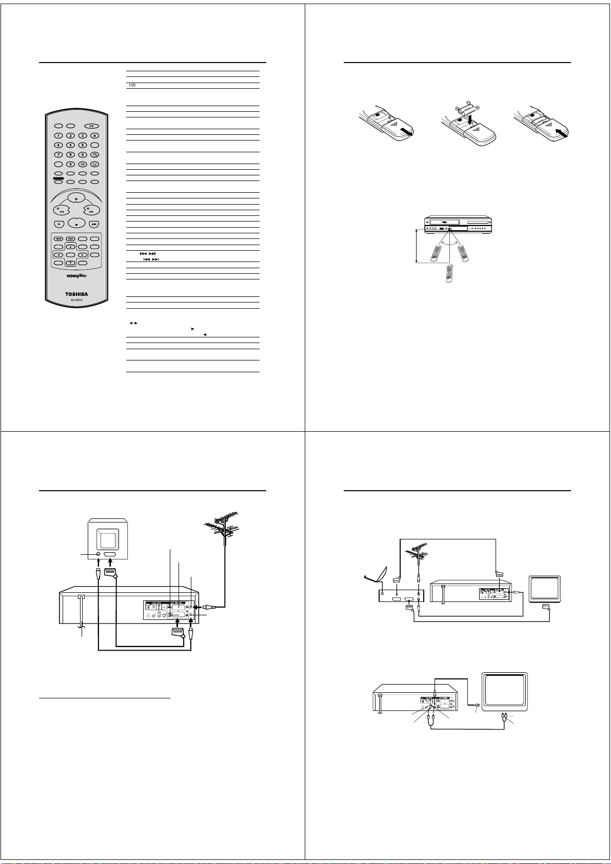
Parts and functions
Front
INPUT SELECT button
Cassette Loading Slot
EJECT button
ON/STANDBY
button
AUDIO (L/R)/
VIDEO IN jacks
Rear
AC power cord
DVD OPTICAL
DIGITAL AUDIO
CHANNEL buttons
OUT jack
DVD COAXIAL DIGITAL
AUDIO OUT jack
DVD AUDIO (L/R) OUT jacks
DVD S-VIDEO OUT jack
Remote sensor
VCR/DVD mode selector button
VCR indicator
Display window
DVD indicator
STOP button
SCART-socket
(for VCR/DECODER)
SCART-socket
(for TV-RGB/Composite)
OPEN/CLOSE button
Disc tray
FWD (Fast Forward) button
REW (Rewind) button
PLAY button
REC button
RF IN jack
RF OUT jack
Display
Display window
No. Display Description
1
2
3
4
5
6
7
8
Note:
Some discs may be displayed wrong or e.g. chapter number, playback time, etc. may not be displayed.
2
1
3
8
VCR
10 : 00
01
tr 2
2
L1/L2/L3
SP
VCR
SLP
7
6
Play indicator (VCR)
Video tape is in the unit
VCR mode of TV/VCR switch
Play indicator (DVD)
Clock display (colon[ : ] flashes)
Counter display by hour/minute/second
H 00M 00S
Track number display for CD
TV channel position display
CH
External input display
Tape speed indicator (VCR)
Timer recording display
Normal recording display (flashes during Recording PAUSE mode)
CH
5
4
SM
6
7
Page 4
Remote control
DVDVCR
OPEN/CLOSE
CLOCK
COUNTER
ANGLE
COUNTER RESET
AUDIO
SUBTITLE
AUXTV/VCR
AUDIO SELECT
ATR
PLAY MODE
ZOOM
MEMORY
E.A.M
SP/LP
REC/OTR
ENTER
DISPLAY
RETURN
CALL
PLAY
PAUSE/STILL
STOP
A-B RPT
TITLE
ZERO RETURN
CH +
MENU
INSTANT SKIP
SET +
CH –
VIDEO Plus+
TIMER REC
REW FWD
SLOW
INDEX – SKIP INDEX +
SET UP
VCR MENU
SET –
CANCEL
8
VCR
DVD
0-9 Direct channel selection of TV 24,26
OPEN/CLOSE Open or Close the tray 38
CLOCK COUNTER
ANGLE Change playback angle of a DVD disc 45
COUNTER RESET
TV/VCR Switches between TV and VCR 25
AUX Scart input or AV-Front input 35
AUDIO Change sound track language of DVD 44
AUDIO SELECT Switches sound 33
SUBTITLE Set Subtitle of a DVD disc 44
ATR Digital AUTO TRACKING 20
MEMORY Index for DVD 42
ZOOM Zoom (for DVD playback) 40
E.A.M Switch a preferred audio enhancement 54
PLAY MODE Select playback mode 41,42
SP/LP Sets the tape speed for recording 24,26,35
TIMER REC
REC/OTR Recording 24,26,35
RETURN Remove DVD set up menu 46
DISPLAY CALL Display VCR or DVD operation status 24~25,56
PLAY Playback 19,38,43
REW Rewind/Review playback 19,20,39
FWD Fast Forward/Forward search playback 19,20,39
STOP Stop 19,38,43
SLOW Slow motion playback 20,39
PAUSE/STILL Still picture/Recording pause on/off 20,24,35,39
SKIP
INDEX / Search for the INDEX mark of a tape 23
TITLE Select title of a DVD disc 45
A-B RPT Repeat playback between A and B (DVD/CD) 41
SET UP VCR MENU
CH +/– Select channel of the connected TV or VCR
▲/▼ Cursor buttons
MENU Display menu of DVD software 45
ZERO RETURN
SET –/+ Setting buttons 28~30
/ Cursor buttons - To move Up in the VCR menu
ENTER
INSTANT SKIP Skip the unwanted short material of a tape 20
CANCEL Delete Timer program 31
VIDEO Plus+ VIDEO Plus Recording 27
Switch to operate VCR 14
Switch to operate DVD 37
On/Standby 14
Input setting 16~17,24,26,42,43
Enter a password 46
Change the clock and tape counter 22
Reset the counter to 00:00 22
Set the unit to start recording at a preset time.
/ Skip chapter to forward or reverse direction 39
Display menu of setup 14~17,20~21,46~55
Stop the tape when the counter reaches 00:00:00
Manual tracking buttons in playback mode 20
you press the
. To move Down in the VCR
menu you press the .
Enter information in the menu/Select option in the menu
Cancel input data in the setting mode
Confirmation of Timer Recording 31
Page
28,30
15,24,26,35
27,31,42~46
Remote control
How to install the batteries
Use micro batteries type AAA.
Slide the battery compartment
1
cover in the direction of the
arrow.
Battery precautions
The precautions below should be followed when using batteries in this device:
1.Use only the size and type of batteries specified.
2.Be sure to follow the correct polarity when installing the batteries as indicated in the battery compartment.
Reversed batteries may cause damage to the device. To avoid a potential short circuit, insert the “–” end first.
3.Do not mix different types of batteries together (e.g. Alkaline and Carbon-zinc) or old batteries with fresh ones.
4.If the device is not to be used for a long period of time, remove the batteries to prevent damage or injury from
possible battery leakage.
5.Do not try to recharge batteries not intended to be recharged; they can overheat and rupture.
Distance of Remote
Control Operation
approx.
2
5m
Install two "AAA" batteries (supplied),
paying attention to the polarity
diagram in the battery
compartment.
Effective angle:
approx. 60°
Point the remote
control directly at the
remote sensor.
Replace the compartment
3
cover.
22
9
Connections and Installation
Connect your DVD/VCR to your home's aerial and to your TV-set as shown in the illustration.
When you have finished these connections you connect your DVD/VCR to the 230-240 V / 50 Hz mains.
TV
Aerial-Input
TV Scart Socket (A1)
To Scart socket
DVD/VCR
AC power cord 230V/50 Hz
Scart cable (not supplied)
Supplied Coaxial cable
Connect a TV with the Scart socket
In addition to the coaxial cable connection, connect also with scart cable. The picture and sound will be transmitted
best through the scart cable. In this case, the TV need not be tuned to the video recorder. The Video channel also
need not be tuned. The video recorder switch the television to video operation through the scart cable automatically.
The stereo-playback is possible in only case through a scart cable!
If your TV-set does not switch to video-playback operation automatically, please
turn your TV's video switch to VIDEO position manually.
Aerial
VCR/DECODER
Scart Socket (A2)
RF-Input (from
house antenna)
RF-Output (to TV)
Playback connection
The exact arrangement you use to interconnect various video and audio components to the DVD/VCR is
dependent on the model and features of each component. Check the Owner's Manual provided with each
component for the location of SCART socket.
Connection to a Satellite Receiver
If a Satellite Receiver is used, we recommend the following configuration:
SCART-cable (not supplied)
Satellite
Aerial
Satellite
Receiver
To record from Satellite Receiver press "AUX" on the remote control of DVD/VCR twice. "A2" will appear on the
front display. Select the desired TV-program at Satellite Receiver.
DVD/VCR
SCART-cable (not supplied)
Connect to a TV with S-Video Output
TV
DVD/VCR
Audio (L) Output
Audio (R) Output
S-Video Cord (not supplied)
To S-Video Input
S-Video Output
AUDIO Cord (not supplied)
Notes:
• The S-VIDEO jack is useful only for DVD section.
• If you use the connection with S-Video Cord, set the “Video Out Select” (P.40) to “Video”.
TV
To Audio (R) Input
To Audio (L) Input
10
11
Page 5
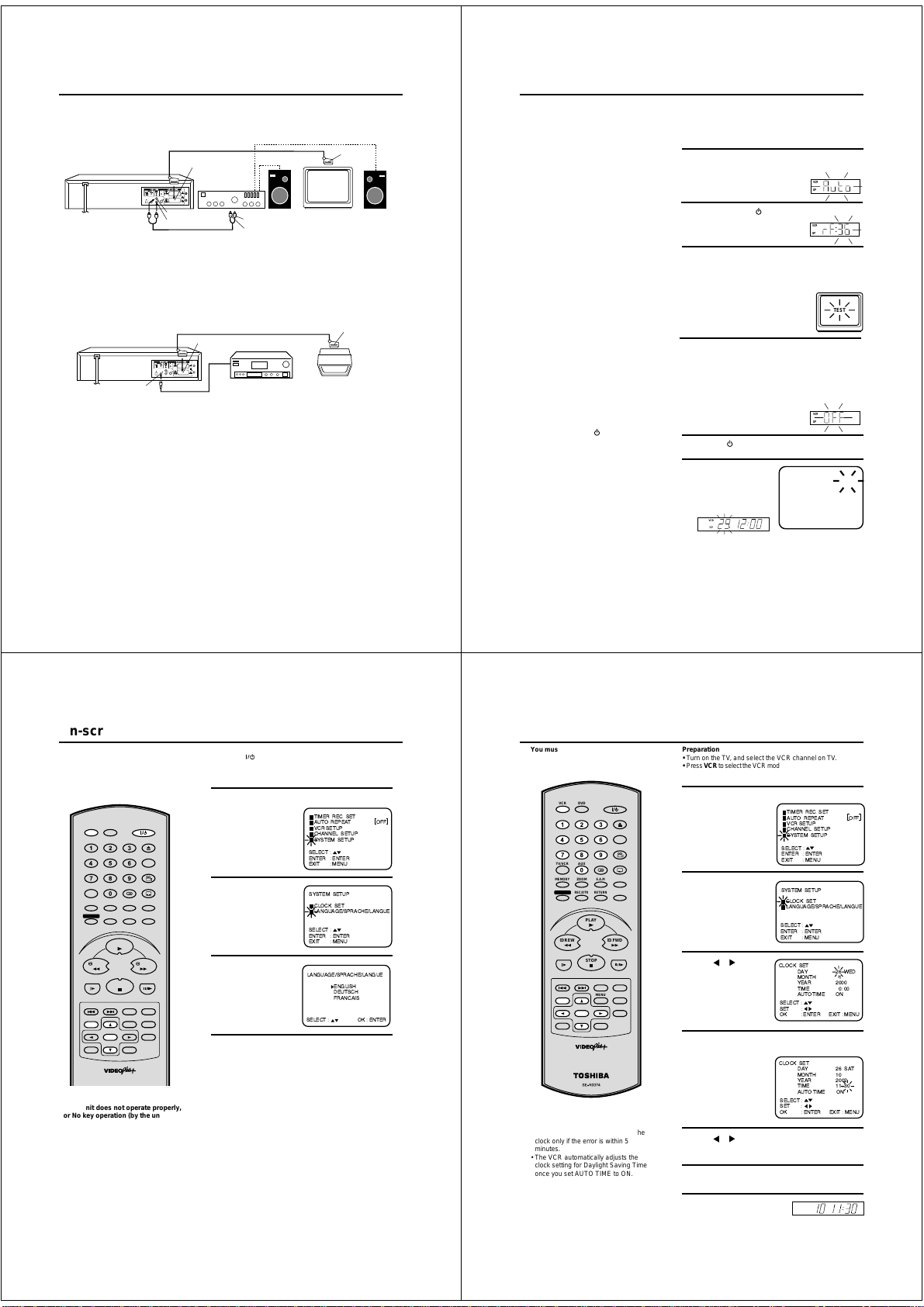
Playback connection
Connect to a Stereo Amplifier with Audio Output
If your DVD/VCR is connected to a stereo amplifier, the video soundtrack can output through the loudspeakers of
the stereo system.
DVD/VCR
SCART-cable (not supplied)
SCART-Socket
(for TV-RGB/Composite)
To SCART
input
Stereo Amplifier
Audio (L) Output
Audio (R) Output
AUDIO Cord (not supplied)
Connect to an AV Amplifier with built-in digital surround
If you are using an Amplifier with a built-in digital surround as follows, you can enjoy the various audio systems
such as Dolby Digital and DTS by using the Coaxial Digital Output.
Use this connection to connect an:
• AV amplifier with built-in *Dolby Digital decoder
• AV amplifier with built-in *DTS decoder
DVD/VCR
To Audio (L) Input
To Audio (R) Input
SCART-cable (not supplied)
SCART-Socket
(for TV-RGB/Composite)
TV
To SCART
input
TV
Coaxial digital
Connecting the optical digital cable
You may connect to an A V Amplifier with an Optical digital cab le (not supplied) instead of a Coaxial digital
cable.
When you connect the optical digital cable (not supplied), remove the dust protection cap from the rear panel.
When not using the optical digital cable, attach the dust protection cap to protect against dust.
NOTES:
• The OPTICAL, COAXIAL jacks are useful only for DVD section.
VHS signal is output only from the SCART-sockets, AUDIO L/R jacks and RF OUT jack.
• When you make the connections above, do not set DOLBY DIGITAL to DOLBY DIGITAL or DTS to ON on the A V
Amplifier. If you do, a loud noise will suddenly come out from the speakers, affecting your ears or causing the
speakers to be damaged.
• DTS audio will be output only from the COAXIAL output. To hear DTS audio, DTS-Decoder is necessary.
When playing DTS-encoded CDs, only noise will be heard from the speakers or analogue stereo outputs.
• Some DTS decoders which do not support DVD-DTS interface may not work properly with the unit.
Audio Output
Coaxial digital cable
(not supplied)
AV Amplifier with
built-in various
decoder as above
12
Tuning the TV Stations and Setting the Time and
Plug your DVD/VCR into the mains supply and it will start to automatically tune
itself in and set the correct date and
time. After setting itself up, you must
set the TV to the video channel.
Notes:
• The DVD/VCR automatically corrects
the clock setting every hour and
automatically adjusts the clock setting
for Daylight Saving Time.
• Your DVD/VCR will tune the TV
stations as follows.
CH 1 BBC 1
CH 2 BBC 2
CH 3 ITV
CH 4 Channel 4
CH 5 Channel 5
CH 6 Satellite
CH 7 etc.
For VIDEO Plus+ recording to work
correctly, this order should not be
changed.
• If you want to change the RF output
channel or switch to "OFF", press and
hold the DVD/VCR
your DVD/VCR in the Standby mode
until the current RF output channel
appears. Press CHANNEL on your
DVD/VCR to select the RF channel you
desire.
• Skipped channels still may be selected
directly through the 1 to 0 keys.
• To cancel skipping select the skipped
channel using the 1 to 0 keys, then
press CANCEL. The channel No. does
not blink any longer, and the channel
No. now may be selected again using
CHANNEL.
on the front of
Preparation
•
Make sure that your DVD/VCR is connected properly to the TV.
•
If a satellite receiver is connected with the coaxial lead, make
sure it’s switched ON and set to SKY ONE.
•
Turn on the TV and select the channel you wish to allocate for
video use.
Plug your DVD/VCR's plug into the mains supply. "Auto"
1
will start to flash in the display. Your DVD/VCR will automatically tune itself in and set the correct
time and date (This may take
approx. 4 minutes).
Press and hold the
2
VCR in the Standby mode until "rF"
and RF output channel "36" will
appear in the display.
If you have used a 21PIN scart lead you now, simply se-
3
lect the AV channel on your TV and go to step 5. Tune the
TV in the same way as tuning in a TV broadcast station
until the word "TEST" flashes on the TV screen. Refer to
the TV operating instructions for tuning.
Now the output from the DVD/VCR is
tuned to this channel. Whenever you
want to play back a tape, select this
channel.
If there is interference in the picture (wavy lines, picture
4
roll, etc.), press CHANNEL on your DVD/VCR to select
any RF channel between 23 and 69, retuning your TV until
the word "TEST" flashes on the TV screen.
If you connected a satellite receiver as explained on page
11, you must switch off the DVD/VCR’s transmitter. Press
the VCR’s CHANNEL repeatedly until OFF appears in the
display window (OFF will appear
after 69 or before 23).
Press the button to turn OFF the DVD/VCR.
5
Now the TV is tuned to your DVD/VCR.
To skip a channel position
Unwanted channels can be
skipped so that they cannot
be called up by pressing
CHANNEL. Select the
channel to be skipped,
...e.g. channel 29. Select channel 29, then press
CANCEL.
This channel’s number will be flashing. That way you can
cancel further channels one after the other.
Date Automatically
button on the front of your DVD/
VCR
SP
CH
VCR
SP
VCR
SP
TEST
VCR
SP
CH 29
13
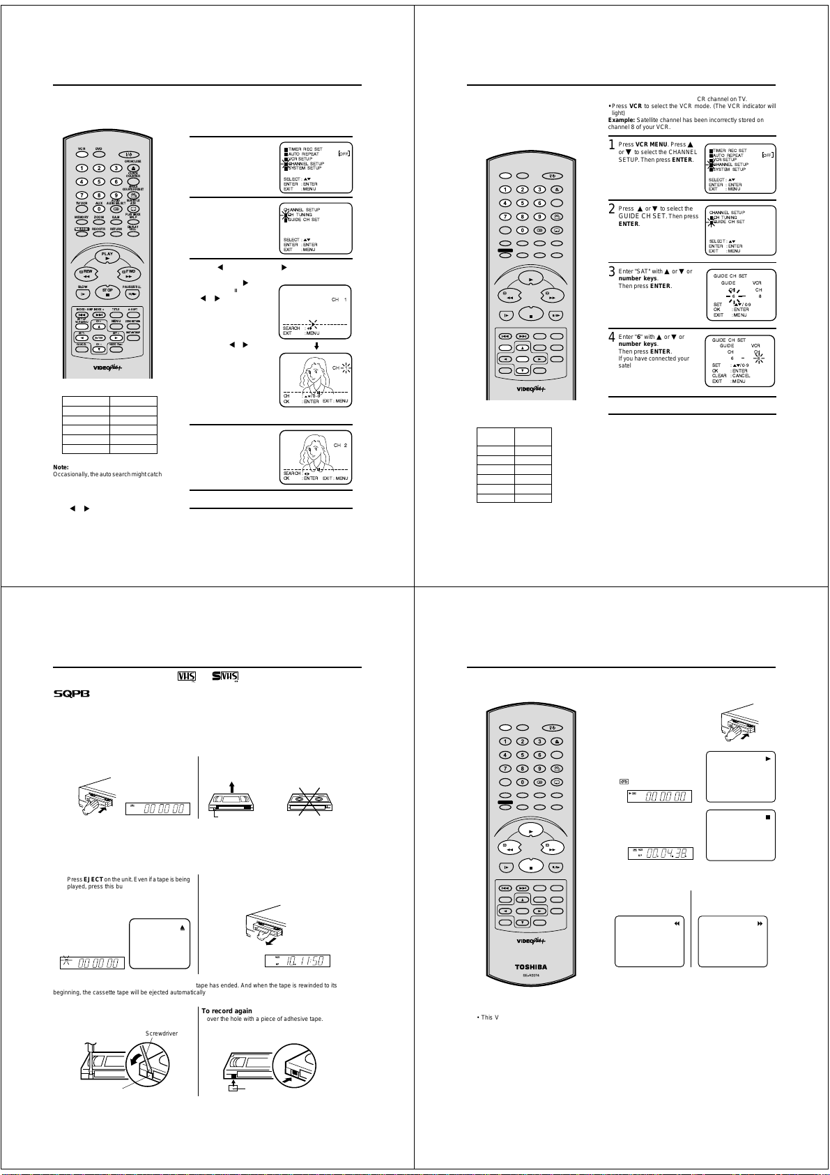
On-screen Language Selection
Turn on your TV and select the VCR
channel which you have already tuned
on your TV. The TV will switch to AV
(VCR mode) automatically by the Scart
lead connection. The on-screen menu
can display any of three languages;
English, German and French.
DVDVCR
OPEN/CLOSE
CLOCK
COUNTER
ANGLE
COUNTER RESET
AUDIO
SUBTITLE
AUXTV/VCR
AUDIO SELECT
ATR
PLAY MODE
ZOOM
MEMORY
E.A.M
SP/LP
REC/OTR
DISPLAY
RETURN
CALL
PLAY
FWD
PAUSE/STILL
STOP
A-B RPT
TITLE
ZERO RETURN
CH +
MENU
INSTANT SKIP
SET +
ENTER
CH –
VIDEO Plus+
TIMER REC
REW
SLOW
INDEX – SKIP INDEX +
SET UP
VCR MENU
SET –
CANCEL
Notes:
• If the unit does not operate properly,
or No key operation (by the unit and /
or the remote control): Static electric-
ity, etc., may affect the player’s operation. Disconnect the AC power cord once,
then connect it again.
• If you use the unit for the first time and
press VCR MENU, instead of the MENU
screen in steps 1 and 2, the one in step 3
may appear. This is normal for this DVD/
VCR and is no indication of a malfunction.
Please first select the language to operate this unit.
Preparation
• Press the
• Press VCR to select the VCR mode. (The VCR indicator will
light)
Press VCR MENU. Press ▲ or ▼ to select the SYSTEM
1
SETUP.
Then press ENTER.
Press ▲ or ▼ to select
2
the LANGUAGE. Then
press ENTER.
Press ▲ or ▼ to select
3
the desired language.
Then press ENTER.
Press VCR MENU repeatedly until the TV picture
4
appears on the screen.
14
button to turn on the DVD/VCR.
TIMER REC SET
AUTO REPEAT OFF
VCR SETUP
CHANNEL SETUP
SYSTEM SETUP
SELECT :
ENTER
: ENTER
EXIT
: MENU
SYSTEM SETUP
CLOCK SET
LANGUAGE/SPRACHE/LANGUE
SELECT :
ENTER
: ENTER
EXIT
: MENU
LANGUAGE/SPRACHE/LANGUE
ENGLISH
DEUTSCH
FRANCAIS
SELECT : OK : ENTER
Setting the Time and Date Manually
You must set the date and time manually
for timer recordings if Automatic tuning
process did not set them correctly.
DVDVCR
OPEN/CLOSE
CLOCK
COUNTER
ANGLE
COUNTER RESET
AUDIO
SUBTITLE
AUXTV/VCR
AUDIO SELECT
ATR
PLAY MODE
ZOOM
MEMORY
E.A.M
SP/LP
REC/OTR
ENTER
DISPLAY
RETURN
CALL
PLAY
PAUSE/STILL
STOP
A-B RPT
TITLE
ZERO RETURN
CH +
MENU
INSTANT SKIP
SET +
CH –
VIDEO Plus+
TIMER REC
REW FWD
SLOW
INDEX – SKIP INDEX +
SET UP
VCR MENU
SET –
CANCEL
Notes:
• The AUTO TIME function adjusts the
clock only if the error is within 5
minutes.
• The VCR automatically adjusts the
clock setting for Daylight Saving Time
once you set AUTO TIME to ON.
Preparation
• Turn on the TV, and select the VCR channel on TV.
•
Press VCR to select the VCR mode. (The VCR indicator will light)
Example: Setting the clock to 11:30, 26 Oct. 2002.
Press VCR MENU. Press ▲ or ▼ to select
1
SETUP. Then press
ENTER.
The step-2 will appear
when clock is not set.
Press ▲ or ▼ to select
2
the CLOCK SET. Then
press ENTER.
Press or repeatedly
3
until 26 appears. Then
▼ to continue.
press
Set the month, year, hour and minute in the same way
4
as in step 3. Then press ENTER.
• In case of an error,
press
▲ to go back to
one step and enter
again.
Press or to select AUTO TIME ON or OFF.
5
The VCR automatically corrects the clock setting every
hour once you set AUTO TIME to ON.
Press VCR MENU repeatedly until the TV picture
6
appears on the screen.
The clock will begin operation.
7
the
: ENTER
: MENU
: ENTER
: MENU
DAY
MONTH
YEAR
TIME
AUTO TIME ON
:
DAY
MONTH
YEAR
TIME
AUTO TIME ON
:
VCR
SP
CH
SYSTEM
26 WED
1
2000
0: 00
26 SAT
10
2002
11: 30
TIMER REC SET
AUTO REPEAT OFF
VCR SETUP
CHANNEL SETUP
SYSTEM SETUP
SELECT :
ENTER
EXIT
SYSTEM SETUP
CLOCK SET
LANGUAGE/SPRACHE/LANGUE
SELECT :
ENTER
EXIT
CLOCK SET
SELECT :
SET
OK : ENTER EXIT : MENU
CLOCK SET
SELECT :
SET
OK : ENTER EXIT : MENU
15
15
Page 6
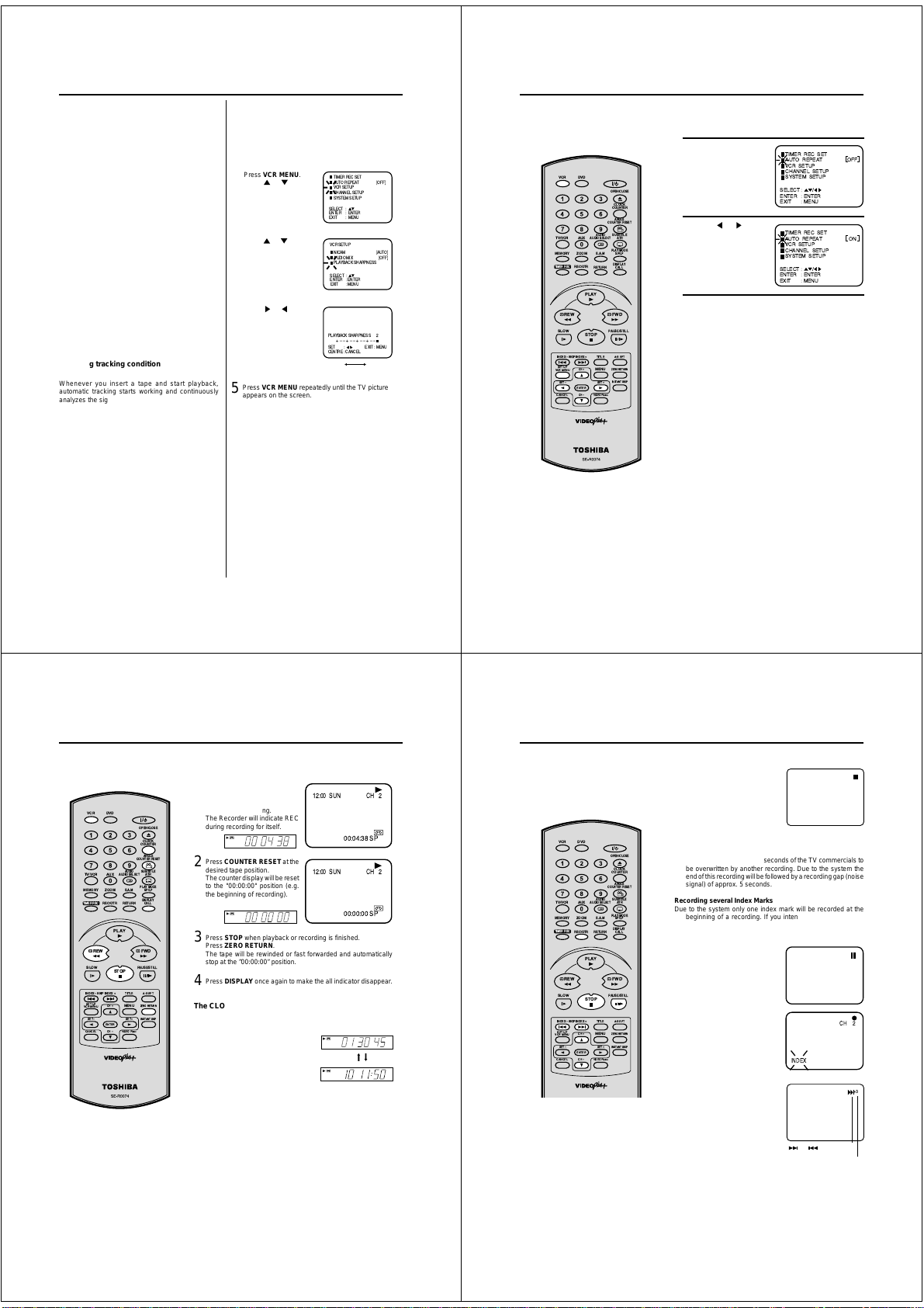
Tuning the TV Stations Manually
This VCR has one built-in tuner to
receive broadcasts. Before you
record a TV broadcast, you must set and
preset all channels. This VCR can preset
up to 80 channels.
DVDVCR
OPEN/CLOSE
CLOCK
COUNTER
ANGLE
COUNTERRESET
AUDIO
SUBTITLE
AUXTV/VCR
AUDIOSELECT
ATR
PLAYMODE
ZOOM
MEMORY
E.A.M
SP/LP
REC/OTR
DISPLAY
RETURN
CALL
PLAY
PAUSE/STILL
STOP
A-BRPT
TITLE
ZERORETURN
CH+
MENU
INSTANTSKIP
SET+
ENTER
CHÐ
VIDEOPlus+
BBC 1
BBC 2
ITV
CH4
CH5
SATELLITE
TIMERREC
REW FWD
SLOW
INDEXÐ SKIPINDEX +
SETUP
VCRMENU
SETÐ
CANCEL
CH 01
CH 02
CH 03
CH 04
CH 05
CH 06
Note:
Occasionally, the auto search might catch
a weak signal and stop. If the TV station
signal is weak, you shouldn't store this
station.
In that case restart the auto search
or .
using
16
Preparation
• Turn on the TV, and select the VCR channel on TV.
• Press VCR to select the VCR mode. (The VCR indicator will
light)
Example: Preset the BBC 2 on programme position 2.
Press VCR MENU.
1
▲ or ▼ to select the
Press
CHANNEL SETUP . Then
press ENTER.
Press ▲ or ▼ to select the
2
CH TUNING.
Press ENTER to select CH
TUNING screen.
Press (falling frequency) or (rising frequency)
3
once to start the search. It stops at each broadcast
automatically (" "
changes to " "). Press
or repeatedly until
BBC 2 appears. Only in
case of receiving a weak
broadcast (drifting
picture), does search fail
to stop. If you want to
stop, press
Press ENTER to preset.
The search menu screen
will disappear if the next
mode is not activated in
less than 50 seconds.
Press ▲ or ▼ repeatedly
4
until 2 is displayed. (Or
enter 0 2 with the 1 to 0
numbered keys). Then
press ENTER.
Repeat the steps 3 and 4 to preset other TV stations.
5
Press VCR MENU repeatedly until the TV picture
6
appears on the screen.
or .
TIMER REC SET
AUTO REPEAT OFF
VCR SETUP
CHANNEL SETUP
SYSTEM SETUP
SELECT :
ENTER
: ENTER
EXIT
: MENU
CHANNEL SETUP
CH TUNING
GUIDE CH SET
SELECT :
ENTER
: ENTER
EXIT
: MENU
SEARCH :
MENU
EXIT :
CH : / 0Ð9
EXIT :MENU
ENTER
OK :
SEARCH :
EXIT :MENU
OK : ENTER
CH 1
CH 1
CH 2
Setting the VIDEO Plus +® Channel Number (Guide CH)
The TV stations must be stored according
to the tuning guide given on page 13,
otherwise the VIDEO Plus+ feature will not
work. If for any reason you did not select
channels BBC1, BBC2, ITV, CH4, CH5 and
Satellite in channel positions 1 through to 6
respectively, you must set each VIDEO Plus+
channel number (GUIDE CH) manually.
DVDVCR
OPEN/CLOSE
CLOCK
COUNTER
ANGLE
COUNTER RESET
AUDIO
SUBTITLE
AUXTV/VCR
AUDIO SELECT
ATR
PLAY MODE
ZOOM
MEMORY
E.A.M
SP/LP
REC/OTR
PLAY
STOP
CH +
ENTER
CH –
GUIDE CH
1
2
3
4
5
6
RETURN
TITLE
MENU
SET +
VIDEO Plus+
DISPLAY
CALL
PAUSE/STILL
A-B RPT
ZERO RETURN
INSTANT SKIP
TIMER REC
REW FWD
SLOW
INDEX – SKIP INDEX +
SET UP
VCR MENU
SET –
CANCEL
GUIDE CHANNEL TABLE
TV
STATION
BBC1
BBC2
ITV
CH4
CH5
Satellite
Preparation
• Turn on the TV, and select the VCR channel on TV.
• Press VCR to select the VCR mode. (The VCR indicator will
light)
Example: Satellite channel has been incorrectly stored on
channel 8 of your VCR.
Press VCR MENU. Press ▲
1
or ▼ to select the CHANNEL
SETUP. Then press ENTER.
Press ▲ or ▼ to select the
2
GUIDE CH SET. Then press
ENTER.
Enter "SAT" with ▲ or ▼ or
3
number keys.
Then press ENTER.
Enter "6" with ▲ or ▼ or
4
number keys.
Then press ENTER.
If you have connected your
satellite using the scart
socket, you must select "AV"
for the VCR CH number.
For other Codes, repeat steps 3 and 4.
5
Press VCR MENU repeatedly until the TV picture ap-
6
pears.
TIMER REC SET
AUTO REPEAT OFF
VCR SETUP
CHANNEL SETUP
SYSTEM SETUP
SELECT :
ENTER
: ENTER
EXIT
: MENU
CHANNEL SETUP
CH TUNING
GUIDE CH SET
SELECT :
ENTER
: ENTER
EXIT
: MENU
GUIDE CH SET
GUIDE6VCR
CH CH
SET : /0-9
OK
: ENTER
EXIT
: MENU
GUIDE CH SET
GUIDE6VCR
CH CH
SET : / 0-9
: ENTER
CLEAROK: CANCEL
EXIT : MENU
8
6
17
Loading and Unloading a Cassette Tape
Use only video cassette tapes marked and .
• Cassettes marked “VHS” (or “S-VHS”) can be used with this video cassette recorder. However, S-VHS recording
is not possible with this model.
• This model is equipped with SQPB (S-VHS QUASI PLAYBACK) that makes it possible to play back S-VHS
recordings with regular VHS resolution.
• HQ VHS is compatible with existing VHS equipment.
• SQPB playback can be seen only at PAL SP mode.
Loading
Push the centre of the tape until it is automatically
inserted.
VCR
S P
H
Automatic power ON
When you insert a cassette tape the DVD/VCR power will turn ON automatically.
Automatic playback
When loading a cassette tape without an erase prevention tab, playback will start automatically.
Unloading
Press EJECT on the unit. Even if a tape is being
12
played, press this button only once.
VCR
S P
Automatic tape eject
This VCR will automatically rewind the tape when the tape has ended. And when the tape is rewinded to its
beginning, the cassette tape will be ejected automatically.
To prevent accidental erasure
Remove the erase prevention tab with a screwdriver.
SM
H
Insert the cassette tape with its labeled side facing up
and the erase prevention tab positioned at your left.
An inverted cassette tape cannot be inserted.
SM
Erase prevention tab
Remove the cassette tape.
VCR
SP
To record again
Cover the hole with a piece of adhesive tape.
CH
Screwdriver
Erase prevention tab
Adhesive tape
18
DVDVCR
OPEN/CLOSE
CLOCK
COUNTER
ANGLE
COUNTER RESET
AUDIO
SUBTITLE
AUXTV/VCR
AUDIO SELECT
ATR
PLAY MODE
ZOOM
MEMORY
E.A.M
SP/LP
REC/OTR
ENTER
DISPLAY
RETURN
CALL
PLAY
PAUSE/STILL
STOP
A-B RPT
TITLE
ZERO RETURN
CH +
MENU
INSTANT SKIP
SET +
CH –
VIDEO Plus+
TIMER REC
REW FWD
SLOW
INDEX – SKIP INDEX +
SET UP
VCR MENU
SET –
CANCEL
• This VCR selects the playback tape
speed SP or LP automatically.
• The Cassette tape and DVD disc can
be played back simultaneously. If you
press VCR or DVD, the tape playback
and DVD playback alternate with each
other on the screen.
Cassette tape playback
Preparation:
• Turn on the TV, and select the VCR channel on TV.
• Press VCR to select the VCR mode. (The VCR indicator will light)
Load a prerecorded tape
1
(When loading a cassette tape
without the erase prevention
tab, playback will start automatically).
To start playback
2
Press PLAY.
Playback will start.
If the cassette has not loaded
yet,
will blink for 4 seconds.
VCR
S P
To stop playback
Press STOP.
VCR
SP
To rewind the tape or forward it rapidly
Stop the playback or recording with STOP.
To rewind the tape:
Press REW.
To stop the tape-winding, press STOP. To switch to playback
directly (without 3), press PLAY.
Forward/Reverse picture search mode
When the tape is being winded, you can switch to picture search
mode (see next page). To do this, press REW or FWD and hold
it down. The unit will resume the tape winding as soon as the
button is released.
NTSC video cassette playback
When using a pre-recorded NTSC video cassette tape, the
connected TV set must operate with a 60 Hz vertical frequency.
Otherwise the on-screen picture will be affected by vertical
rolling. Even if your VCR set is capable of processing NTSC video
signals, the picture may be shortened vertically (appearance of
black bars at the top and at the bottom of the TV screen). The
dubbing of a NTSC video cassette tape to a standard PAL VCR
is not possible.
H
H
SM
SM
To forward the tape:
Press FWD.
19
Page 7
Special playback/Playback sharpness/Skip Search
Special playback
Picture Search
Reverse picture search function
Press REW x 1 or x 2 during the playback.
Forward picture search function
Press FWD x 1 or x 2 during the playback.
To return to playback: Press PLAY.
Still Picture
Press PAUSE/STILL during playback. To resume
normal playback: Press PLAY.
Slow Motion
During playback press SLOW.
You can change the slow speed by the additional
pressing of SLOW.
To return to playback: Press PLAY.
Slow tracking and vertical lock adjustment
If noise bars appear in the picture during slow motion,
press the SET + or – to reduce the noise bars.
If the still picture jitters excessively, press SET + or –
to stabilize the still picture.
Frame by Frame picture
During playback, press PAUSE/STILL one by one:
The picture advances frame by frame.
To return to playback: Press PLAY.
Adjusting tracking condition
Automatic tracking adjustment
Whenever you insert a tape and start playback,
automatic tracking starts working and continuously
analyzes the signal to enable optimum picture quality
during playback.
Manual tracking adjustment
If automatic tracking cannot eliminate noises well during
playback, press SET + or SET – to eliminate the noises.
“MANUAL TR.” will appear. Press it briefly for a fine
adjustment, or press and hold for a coarse adjustment.
To return to automatic tracking, press A. TRK.
Notes:
The audio output is muted during SPEED SEARCH,
•
STILL, FRAME ADVANCE and SLOW MOTION.
• During picture search mode there will be noise bars
which are caused by the system.
• The Special Playback will automatically change to
playback after approx. 5 minutes to protect the video
tape against excessive wear.
Playback sharpness
Adjust the sharpness of playback picture during
playback. During slow motion, still picture and picture
search, sharpness-adjusting is impossible.
Start the playback of video tape.
1
Press VCR MENU.
2
Press
or to select
VCR SETUP. Then press
ENTER.
Press
or to select
3
PLAYBACK SHARPNESS. Then press
ENTER.
Press or to adjust
4
the playback sharpness
to the level you reguire.
Press VCR MENU repeatedly until the TV picture
5
appears on the screen.
Note:
To return to the initial sharpness setting, press CANCEL
while the sharpness setting screen is appearing.
Skip Search
Each time you press INSTANT SKIP while a tape is playing,
the unit will fast-forward ahead 30 seconds on the tape. You
may press the button up to six times in a row to move 180
seconds (three minutes) ahead.
For example: 1 press: Approx. 30 seconds of tape
2 presses: Approx. 60 seconds of tape
3 presses: Approx. 90 seconds of tape
TIMER RECSET
AUTO REPEAT
VCR SETUP
CHANNEL SETUP
SYSTEM SETUP
SELECT :
ENTER : ENTER
MENU
EXIT
:
VCR SETUP
NICAM
AUDIO MIX
PLAYBACK SHARPNESS
SELECT :
ENTER : ENTER
MENU
EXIT :
PLAYBACK SHARPNESS
+ÐÐ+ÐÐ+ÐÐ+ÐÐ
SET :
EXIT :
CENTRE :
CANCEL
softer sharper
[OFF]
[AUTO]
[OFF]
2
MENU
If the Repeat function is switched
on, the playback will continue until
it reaches the tape-end and then
rewind to the beginning of the tape.
This process will repeat until the
unit is turned off.
DVDVCR
OPEN/CLOSE
CLOCK
COUNTER
ANGLE
COUNTERRESET
AUDIO
SUBTITLE
AUXTV/VCR
AUDIOSELECT
ATR
PLAYMODE
ZOOM
MEMORY
E.A.M
SP/LP
REC/OTR
ENTER
DISPLAY
RETURN
CALL
PLAY
PAUSE/STILL
STOP
A-BRPT
TITLE
ZERORETURN
CH+
MENU
INSTANTSKIP
SET+
CHÐ
VIDEOPlus+
TIMERREC
REW FWD
SLOW
INDEXÐ SKIPINDEX +
SETUP
VCRMENU
SETÐ
CANCEL
Note:
To cancel the auto repeat mode, follow the
above steps 1 and 2, then select "OFF"
and confirm by pressing VCR MENU.
To set the Repeat function
Repeat Playback
Preparation
• Turn on the TV and select the VCR channel on TV.
• Press VCR to select the VCR mode.
Press VCR MENU.
1
Press
▲ or ▼
to select the AUTO
REPEAT.
or to select
Press
2
[ON] or [OFF].
Press VCR MENU repeatedly until the TV picture appears.
3
If "ON" has been selected, the tape will be repeatedly
played.
TIMER REC SET
AUTO REPEAT OFF
VCR SETUP
CHANNEL SETUP
SYSTEM SETUP
SELECT : /
ENTER
: ENTER
EXIT
: MENU
TIMER REC SET
AUTO REPEAT ON
VCR SETUP
CHANNEL SETUP
SYSTEM SETUP
SELECT : /
ENTER
: ENTER
EXIT
: MENU
20
Counter Display
ZERO RETURN function
This function makes tape-rewinding
stop at the counter 00:00:00 position
automatically.
DVDVCR
OPEN/CLOSE
CLOCK
COUNTER
ANGLE
COUNTERRESET
AUDIO
SUBTITLE
AUXTV/VCR
AUDIOSELECT
ATR
PLAYMODE
ZOOM
MEMORY
E.A.M
SP/LP
REC/OTR
DISPLAY
RETURN
CALL
PLAY
PAUSE/STILL
STOP
A-BRPT
TITLE
ZERORETURN
CH+
MENU
INSTANTSKIP
SET+
ENTER
CHÐ
VIDEOPlus+
TIMERREC
REW FWD
SLOW
INDEXÐ SKIPINDEX +
SETUP
VCRMENU
SETÐ
CANCEL
Notes:
• When you load a video cassette, the display indication changes to "00:00:00".
• The counter display does not function
on non-recorded (blank) sections of the
tape. When you rewind, fast forward or
play tapes through blank sections, the
counter display stops.
22
Preparation:
• Turn on the TV, and select the VCR channel on TV.
• Press VCR to select the VCR mode. (The VCR indicator will light)
Press DISPLAY.
1
The counter display shows the
tape running time during
playback or recording.
The Recorder will indicate REC
during recording for itself.
VCR
S P
H
Press COUNTER RESET at the
2
desired tape position.
The counter display will be reset
to the "00:00:00" position (e.g.
the beginning of recording).
VCR
S P
H
Press STOP when playback or recording is finished.
3
Press ZERO RETURN.
The tape will be rewinded or fast forwarded and automatically
stop at the ”00:00:00” position.
Press DISPLAY once again to make the all indicator disappear .
4
The CLOCK COUNTER button
Press CLOCK COUNTER during the playback. The clock and tape
counter alternate with each other in the display.
Note:
You can set the tape counter to 00:00:00 with COUNTER RESET
anytime. Therefore, the counter display can also indicate 00:00:00,
even when the tape counter does not reach its beginning yet. Even if
the tape counter indicates 00:00:00, it can be rewinded moreover. If
the tape was rewinded over the point of 00:00:00, the minus mark (–
) appears in the counter display. Although the tape counter seems to
forward when you press REW, in fact the tape is being rewinded.
When the tape reaches the beginning, the tape-rewinding stops
automatically.
12:00 SUN
SM
12:00 SUN
SM
VCR
S P
VCR
S P
CH 2
00:04:38 SP
CH 2
00:00:00 SP
H
CH
21
Video Index Search System
Whenever a recording is begun an
invisible index mark is recorded on the
tape. These index marks are all identical,
and each mark means: "Here starts a
new recording". Every DVD/VCR
equipped with the Video Index Search
System (VISS) can locate these marks
at the beginning of any recording.
DVDVCR
OPEN/CLOSE
CLOCK
COUNTER
ANGLE
COUNTERRESET
AUDIO
SUBTITLE
AUXTV/VCR
AUDIOSELECT
ATR
PLAYMODE
ZOOM
MEMORY
E.A.M
SP/LP
REC/OTR
ENTER
DISPLAY
RETURN
CALL
PLAY
PAUSE/STILL
STOP
A-BRPT
TITLE
ZERORETURN
CH+
MENU
INSTANTSKIP
SET+
CHÐ
VIDEOPlus+
TIMERREC
REW FWD
SLOW
INDEXÐ SKIPINDEX +
SETUP
SM
PM
VCRMENU
SETÐ
CANCEL
Notes:
•
When you record an INDEX mark at
the very beginning of the tape, the
mark may not be found.
•
During INDEX search, the tape may
stop and begin to play at a slightly
different location.
•
INDEX may not function properly with
old or worn out video tapes.
•
INDEX marks may not be found if it is
extremely close to the point where the
search began.
•
In recording, if you stop recording temporarily, the INDEX mark is not recorded on the tape.
Example: Indexing of TV commercials.
1 Start playback and wait until
the end of the TV commercial
is reached, then press STOP.
2 Press REC/OTR. When the "INDEX" on-screen indication
goes off, STOP may be pressed. This short recording
process will be sufficient to set an index mark.
This will result in about 10 seconds of the TV commercials to
be overwritten by another recording. Due to the system the
end of this recording will be followed by a recording gap (noise
signal) of approx. 5 seconds.
Recording several Index Marks
Due to the system only one index mark will be recorded at the
beginning of a recording. If you intend to set several index
marks during a single recording, follow the procedure below:
1 At the point of the recording
where an index mark is to be
set press PAUSE/STILL. The
unit will switch to the recording
pause mode.
2
Press CH repeatedly
back to the original TV
program. Press
to resume recording.
to switch
PAUSE/STILL
CH 2
INDEX
Index Search
Press INDEX + or – during stop
or play mode.
For Succeeding programs:
Press INDEX +.
For Preceding programs:
Press INDEX –.
(Additional press increases the
INDEX NO. up to 9.)
When the INDEX + or – is
pressed, the unit starts
searching the INDEX NO.
selected and finds the portion,
then playback starts automatically.
To stop the Index Search, press
STOP.
or is displayed
INDEX NO. (up to 9)
+3
23
Page 8

Recording a TV Programme
Preparation:
• Turn on the TV, and select the VCR channel on TV.
• Press VCR to select the VCR mode. (The VCR indicator will light)
DVDVCR
OPEN/CLOSE
CLOCK
COUNTER
ANGLE
COUNTERRESET
AUDIO
SUBTITLE
AUXTV/VCR
AUDIOSELECT
ATR
PLAYMODE
ZOOM
MEMORY
E.A.M
SP/LP
REC/OTR
DISPLAY
RETURN
CALL
PLAY
PAUSE/STILL
STOP
A-BRPT
TITLE
ZERORETURN
CH+
MENU
INSTANTSKIP
SET+
ENTER
CHÐ
VIDEOPlus+
TIMERREC
REW FWD
SLOW
INDEXÐ SKIPINDEX +
SETUP
VCRMENU
SETÐ
CANCEL
Notes:
• Since the DVD/VCR has a built-in TV
tuner the TV set may be turned off when
recording. The TV set may only be used
to check for accurate program adjustments or to monitor recordings.
• You can confirm on the TV-screen
whether you selected SP or LP. Press
DISPLAY to see the status display. (see
page 25)
• If you wish to watch the DVD playback
during the normal recording on VCR,
press DVD to change to DVD mode and
perform the DVD playback (see page
38).
Load a blank cassette tape with the
1
erase prevention tab intact. (The
DVD/VCR will automatically turn
on.)
Select the program(e.g.29) you want to record with CH +/– or
2
number keys.
1~9 : e.g. 5 = press “5”
10~80 : e.g. 29 = press “2” and “9”.
If a recording in Long Play mode is intended, press SP/LP to
3
display "LP". (see Note below)
On the VCR, press REC.
4
Or on the Remote, press REC/OTR.
" " will appear on the screen for
about 4 seconds and “
appear on the display.
If the erase prevention tab is removed, the tape will eject when
REC/OTR are pressed for recording. (see p.18)
To Stop Recording
Press STOP.
To Stop Recording Temporarily
To stop a recording for a short
period of time press PAUSE/STILL.
Press this button again if you want
to resume the recording.
Attention:
A safety circuit turns the pause mode off automatically after 5
minutes, and the DVD/VCR will stop the recording mode.
24
Recording a TV Programme
Recording with a SCART Lead:
You can record a programme using
the TV receiver of the DVD/VCR and at
the same time watch another programme on the TV set using its receiver. As the DVD/VCR automatically
switches the TV set the following
points should be observed:
DVDVCR
OPEN/CLOSE
CLOCK
COUNTER
ANGLE
COUNTER RESET
SUBTITLE
AUDIO
AUXTV/VCR
ATR
AUDIO SELECT
PLAY MODE
ZOOM
E.A.M
CH 29
” will
VCR
S P
H
INDEX
SM
MEMORY
TIMER REC
REW FWD
SLOW
INDEX – SKIP INDEX +
SET UP
VCR MENU
SET –
CANCEL
Auto Rewind Feature
The DVD/VCR will automatically rewind
when the tape has ended (except during
OTR and TIMER REC). It will also eject
the cassette tape.
REC/OTR
ENTER
SP/LP
DISPLAY
RETURN
CALL
PLAY
PAUSE/STILL
STOP
A-B RPT
TITLE
ZERO RETURN
CH +
MENU
INSTANT SKIP
SET +
CH –
VIDEO Plus+
Press TV/VCR until "VCR" appears on the display. Select
1
the program on the DVD/VCR you
program
can be watched on the screen and recorded by the
DVD/VCR.
While the VCR is recording press TV/VCR until the "VCR"
2
indicator on the display goes off. The TV set now displays
the program of its built-in receiving module. Select the TV
channel you want to watch on the TV set. Although the TV
set now shows another program the DVD/VCR will continue recording the previously selected programme.
Using TV/VCR you can switch the TV screen between the
3
DVD/VCR picture and the TV picture. If the "VCR" indicator
is lit on the display, you will watch
has no
trouble on the recording.
want to record. This
VCR
S P
H
“VCR” indicator goes on.
S P
H
“VCR” indicator goes off.
the DVD/VCR picture. This
VCR
S P
H
“VCR” indicator goes on.
To Display VCR operation Status
Press DISPLAY. The clock, day of the week and more
informations will be indicated.
To cancel the indicating: Press DISPLAY until all indicator
disappear.
Indication for
Hi-Fi-playback
or stereoreception
Audio Select
Day of the week
Time
23:59 MON
HI-FI
STEREO
Deck-status
here: Playback
CH 80
01:36:58 SP
Tape speed
Stand of Tape counter
Programme
number or
Scart input
LINE1/LINE2/
LINE3
Cassette in
Unit
SM
SM
SM
25
One-touch Timer Recording (OTR)
The one-touch timer recording feature
provides a simple and convenient way
to make a timed recording.
DVDVCR
OPEN/CLOSE
CLOCK
COUNTER
ANGLE
COUNTERRESET
AUDIO
SUBTITLE
AUXTV/VCR
AUDIOSELECT
ATR
PLAYMODE
ZOOM
E.A.M
MEMORY
TIMERREC
REW FWD
SLOW
INDEXÐ SKIPINDEX +
SETUP
VCRMENU
SETÐ
CANCEL
Notes:
• If you wish to watch the DVD playback
during the OTR, press DVD to change
to DVD mode and perform the DVD playback (see page 38).
• If the tape supply has not sufficed for
OTR recording, the clock symbol (
blink at the tape-end and then VCR
mode will change to DVD mode.
In this case, press TIMER REC to cancel
blink or press EJECT to remove
the
the cassette tape.
REC/OTR
SP/LP
DISPLAY
RETURN
CALL
PLAY
PAUSE/STILL
STOP
A-BRPT
TITLE
ZERORETURN
CH+
MENU
INSTANTSKIP
SET+
ENTER
CHÐ
VIDEOPlus+
Preparation:
• Turn ON the TV and select the VCR channel on TV .
• Press VCR to select the VCR mode. (The VCR indicator will light)
Load a blank cassette tape with the
1
erase prevention tab intact. (The
DVD/VCR will automatically turn
on.)
Select the program (e.g.29) you want to record with CH +/– or
2
number keys.
1~9 : e.g. 5 = press “5”
10~80 : e.g. 29 = press “2” and “9”.
If a recording in Long Play mode is intended, press SP/LP (TAPE
3
SPEED) to display "LP". (see note on page 28)
Press REC on the VCR or REC/OTR on the Remote to begin
4
recording. Press REC on the VCR again to stop recording after
30 minutes. Each additional press of REC will increase recording
time as shown in the chart below, up to a
maximum of 5 hours. The OTR and recording time will appear
on the screen for about 4 seconds.
VCR
S P
Tape speed: SP
Recording 0:30
5:00
Tape speed: LP
Recording 0:30
10:00
To Extend the Recording Time
Press REC/OTR repeatedly until the
desired time appears on the display.
To stop the OTR
Press STOP.
) will
26
VIDEO Plus+® Recording
Look up the PlusCode Number in an
appropriate TV programme magazine.
Select the desired TV programme for
recording and refer to the PlusCode
Number next to it.
DVDVCR
OPEN/CLOSE
CLOCK
COUNTER
ANGLE
COUNTERRESET
AUDIO
SUBTITLE
AUXTV/VCR
AUDIOSELECT
ATR
PLAYMODE
ZOOM
E.A.M
MEMORY
TIMERREC
OTR 0:30
CH 29
SM
H
INDEX
1:30
1:00
3:00
5:00
1:00
2:00
1:30
4:00
OTR 1 : 30
2:00
3:00
CH 29
4:00
.......
REW FWD
SLOW
INDEXÐ SKIPINDEX +
SETUP
VCRMENU
SETÐ
CANCEL
Notes:
• The built-in timer stores 8 memories. If
the "PROGRAM FULL" indication
appears, you must delete one memory
(see page 31).
• When the power supply is interrupted
for more than 30 minutes, the preset
programme is cleared. In this case,
you have to set the timer again.
REC/OTR
ENTER
SP/LP
DISPLAY
RETURN
CALL
PLAY
PAUSE/STILL
STOP
A-BRPT
TITLE
ZERORETURN
CH+
MENU
INSTANTSKIP
SET+
CHÐ
VIDEOPlus+
registered trademarks of Gemstar Development Corporation.
The VIDEO Plus+ system is manufactured under license
from Gemstar Development Corporation.
Preparation
• Turn on the TV and select the VCR channel on TV .
• Press VCR to select the VCR mode. (The VCR indicator will
light)
Press VIDEO Plus+.
1
Note: If any button is not
pressed within 60 seconds,
the Recorder switches
back to TV operation.
Enter the PlusCode
2
Number using number
keys.
• In case of an error, press
CANCEL and enter the
desired number again.
Press ▲ or ▼ to select ONCE, DAILY or WEEKLY.
3
ONCE = To record a
programme only once
DAILY = To record TV
programmes transmitted
daily
WEEKLY = To record TV
programmes transmitted
once a week.
Press ENTER. By the PlusCode Number, the entered data
4
appears on the screen.
Select your tape speed.
• If the entered Number
is not correct, the
indicator
NO. ERROR
appear.
Enter the correct number.
VIDEO Plus+ and PlusCode are
"PLUS CODE
" will
PLUSCODE NO.
PLUSCODE
SELECT
CLEAR
OK
EXIT
PLUSCODE NO.
PLUSCODE
SELECT
CLEAR
OK
EXIT
PLUSCODE NO.
PLUSCODE
SELECT
CLEAR
OK
EXIT
PLUSCODE NO.
DATE
START
END
CH
SPEED
PDC
:
SELECT
:
SET
: MENU
EXIT
ONCE
DAILY
WEEKLY
NO.
ONCE
DAILY
WEEKLY
NO.
ONCE
DAILY
WEEKLY
NO.
15 FRI
17:30
18:00
3
SP
OFF
: 0Ð9
:
: CANCEL
: ENTER
: VIDEOPLUS+
57378
: 0Ð9
:
: CANCEL
: ENTER
: VIDEOPLUS+
57378
: 0Ð9
:
: CANCEL
: ENTER
: VIDEOPLUS+
57378
OK :ENTER
27
Page 9
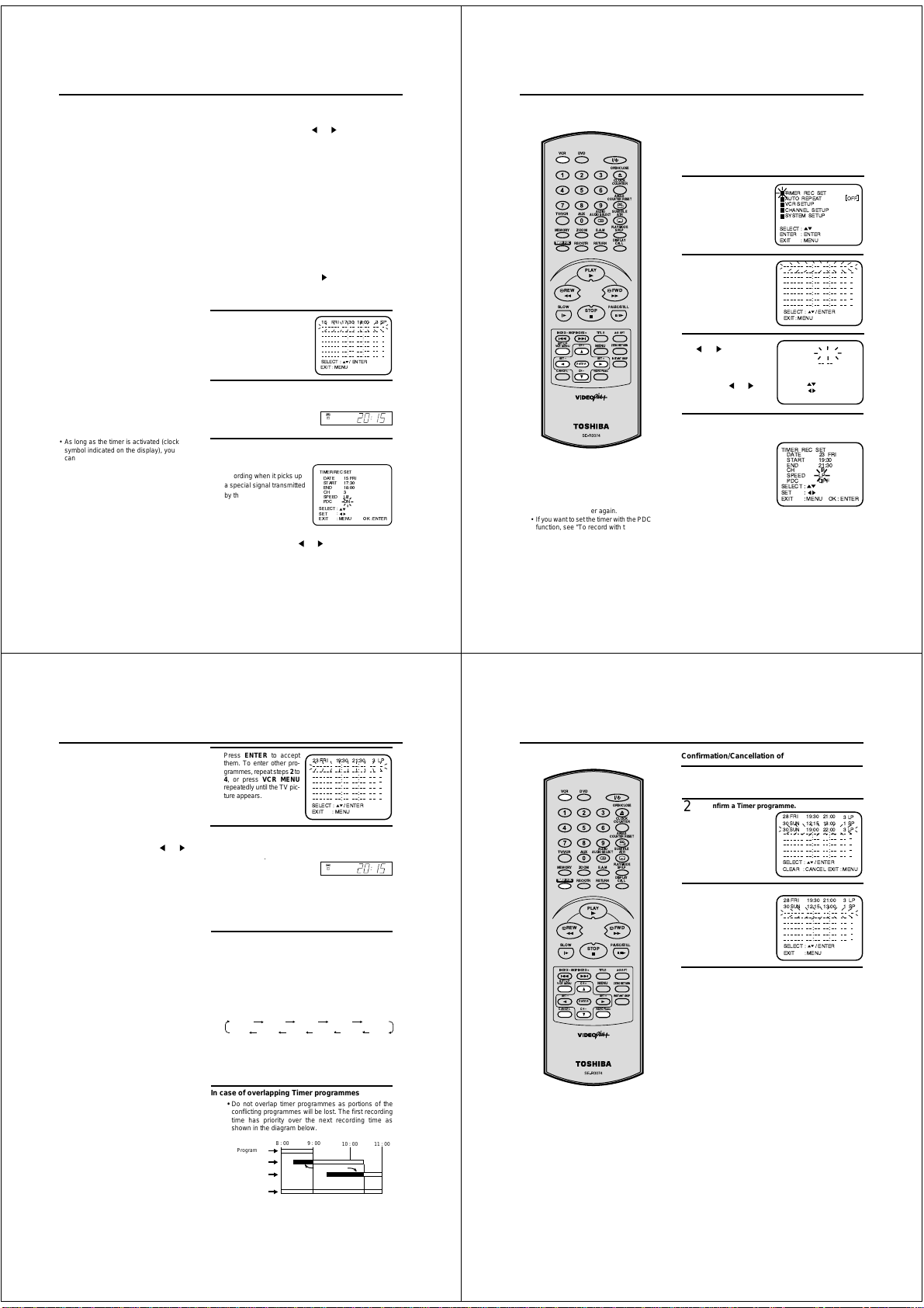
VIDEO Plus+ Recording
Notes:
• As long as the timer is activated (clock
symbol indicated on the display), you
cannot use the VCR. If you want to use
the VCR, first press TIMER REC to
deactivate the timer.
• Not all TV Stations transmit PDC signal
all of the time, therefore it is advisable to
check before setting PDC to ON, if you
do set PDC to ON and no signal is
received your recording might not take
place at all. To check PDC status,
change to the channel on your DVD/VCR
you wish to record from, if the word
"PDC" appears on the screen for a few
seconds then that channel is
broadcasting PDC and you can set the
feature to ON.
28
If you have selected Daily or Weekly in step 3, then you
can select a recording date again. The date must blink.
If it does not blink, then press
the DATE blinks. Then press
the desired date appears. The following date options are
available:
SUN-SAT: all dates from Sunday to Saturday, or
MON-SAT: only from Monday to Saturday, or
MON-FRI: only from Monday to Friday.
WKL-MON: each Monday, WKL-TUE: each Tuesday
WKL-SUN: each Sunday, etc.
Recording period extension
The recording end-time will be set by VIDEO Plus+
automatically. However you can extend the recording
end-time manually. The time END must blink.
If it does not blink, then press
the time end blinks. Then press
Press ENTER after the
5
confirmation. Then press
VCR MENU repeatedly until
the TV picture appears. To
enter another programme,
repeat
steps 1 - 5.
Although the data is stored in the timer memory, the timer
6
function is not yet ready for recording. To accomplish this,
activate it by pressing TIMER REC.
If no cassette tape is loaded,
the clock symbol is blinking.
To record with the PDC (Programme
Delivery Control) system
The PDC system starts
recording when it picks up
a special signal transmitted
by the broadcaster with the
TV programme – even if
the TV programme starts
early, late or runs on longer
than scheduled. In step 4, press ▼ repeatedly until PDC
OFF flashes, then press
recording with PDC.
▲ or ▼ repeatedly until
or repeatedly until
▲ or ▼ repeatedly until
to extend.
15 FRI 17:30 18:00 3
:
:
:
:
:
:
:
SELECT : / ENTER
EXIT
:
MENU
VCR
TIMER RECSET
DATE
15 FRI
START
17:30
END
18:00
CH
3
SPEED
LP
PDC
ON
:
SELECT
:
SET
: MENU
EXIT
or to display "ON" for
:
:
:
:
:
:
:
OK :ENTER
Timer Recording Manually
The built-in timer allows unattended
recording of up to 8 programmes
within 1 month.
DVDVCR
OPEN/CLOSE
CLOCK
COUNTER
ANGLE
COUNTERRESET
SUBTITLE
AUDIO
AUXTV/VCR
ATR
AUDIOSELECT
PLAYMODE
ZOOM
E.A.M
MEMORY
TIMERREC
REW FWD
SP
SLOW
INDEXÐ SKIPINDEX +
SETUP
VCRMENU
SETÐ
CANCEL
Notes:
• When the power supply is interrupted for
more than 30 minutes, the preset
programme is cleared. In this case, you
have to set the timer again.
• If you want to set the timer with the PDC
function, see "To record with the PDC
system" on page 28.
REC/OTR
ENTER
SP/LP
DISPLAY
RETURN
CALL
PLAY
PAUSE/STILL
STOP
A-BRPT
TITLE
ZERORETURN
CH+
MENU
INSTANTSKIP
SET+
CHÐ
VIDEOPlus+
Preparation
• Turn on the TV and select the VCR channel on TV .
• Press VCR to select the VCR mode. (The VCR indicator will
light)
• Load a video cassette with the erase prevention tab intact.
Make sure that the time and date are correct.
Example: Timer recording for the 23rd, Friday, on channel 3,
19:30 to 21:30 and LP mode.
Press VCR MENU.
1
Press
▲ or ▼ to select
the TIMER REC SET.
Then press ENTER.
Each line stands for one
2
programme of the 8
memories. Select one
▲ or ▼ .
line with
Then press ENTER.
Set the desired dates with
3
or . Then press ▼
to accept them.
• Daily/weekly settings
can be found by
pressing
or
repeatedly (see page
30).
Set the Starting time (19:30), ending time (21:30)
4
channel (3) and tape speed (LP) in the same way as in
step 3.
• In case of an error,
press
▲ to go back to
the previous step and
repeat.
TIMER REC SET
AUTO REPEAT OFF
VCR SETUP
CHANNEL SETUP
SYSTEM SETUP
SELECT :
ENTER
: ENTER
EXIT
: MENU
:
:
:
:
:
:
:
:
:
:
:
:
:
:
:
:
ENTER
SELECT : /
:
MENU
EXIT
TIMER REC SET
DATE 23 FRI
11:30
START
:
END
1
CH
SP
SPEED
OFF
PDC
SELECT :
SET :
EXIT : MENU
TIMER REC SET
DATE 23 FRI
19:30
START
21:30
END
3
CH
LP
SPEED
OFF
PDC
SELECT :
SET
EXIT:: MENU
OK : ENTER
29
Timer Recording Manually
Notes:
• In case of a timer recording from the Scart
socket, proceed as follows: When "CH" is
blinking in picture/step 4, press
repeatedly until "LINE" appears.
• If the clock symbol blinks when the timer
recording is completed, the TV programme
has not been completely recorded
because of an insufficient tape supply.
• As long as the timer is activated (clock
symbol indicated on the display), you
cannot use the DVD/VCR. If you want to
use the DVD/VCR, press TIMER REC to
deactivate the timer.
Notes:
•
The daily/weekly recording can be
made continuously until the recording is
cancelled or the tape reaches the end.
•
During timer recording, the automatic
rewinding mechanism does not function.
or
Press ENTER to accept
5
them. To enter other programmes, repeat steps 2 to
4, or press VCR MENU
repeatedly until the TV picture appears.
Although the data is stored in the timer, it is not ready for
6
recording. To start timer recording, press TIMER REC to
turn it on. When no video cassette is loaded, the clock sym-
is blinking
.
bol
When you turn the unit off, the timer will be switched on
automatically. The clock symbol will appear on the display .
If you still want to use the recorder, press
first. Then the clock symbol will disappear from the display.
Weekly (e.g. WKL-TUE: each Tuesday) or daily (e.g.
MON-SAT Monday to Saturday) Timer recording
Follow the procedure for timer recording on the previous
page. In picture/step 3 (when date and day is blinking),
press repeatedly until the desired setting appears
▼
(weekly or daily).
DATE-DAY WKL-FRI WKL-SAT WKL-SUN WKL-MON
SUN-SAT MON-SAT MON-FRI WKL-THU WKL-WED WKL-TUE
23 FRI 19:30 21:30 3 LP
:
:
:
:
:
:
:
:
:
:
:
:
:
:
ENTER
SELECT : /
:
MENU
EXIT
VCR
TIMER REC
Set other START, END, CH, SPEED as previous pages.
In case of overlapping Timer programmes
• Do not overlap timer programmes as portions of the
conflicting programmes will be lost. The first recording
time has priority over the next recording time as
shown in the diagram below.
8 : 00
9 : 00
10 : 00
Program 1
Program 2
Program 3
Recording
Control Settings
Prog.1
Deleted Parts
Non Recorded Portion Parts
11 : 00
Prog.2 Prog.3
DVDVCR
AUXTV/VCR
ZOOM
MEMORY
TIMERREC
REC/OTR
PLAY
REW FWD
SLOW
STOP
INDEXÐ SKIPINDEX +
SETUP
CH+
VCRMENU
SETÐ
ENTER
CHÐ
CANCEL
AUDIO
AUDIOSELECT
E.A.M
RETURN
TITLE
MENU
SET+
VIDEOPlus+
OPEN/CLOSE
CLOCK
COUNTER
ANGLE
COUNTERRESET
SUBTITLE
ATR
PLAYMODE
SP/LP
DISPLAY
CALL
PAUSE/STILL
A-BRPT
ZERORETURN
INSTANTSKIP
Timer Recording Manually
Confirmation/Cancellation of the Timer Recording
If the Timer has been activated, now press TIMER REC to
1
deactivate the timer. The clock symbol will disappear. Then
press VCR to change to VCR mode.
To confirm a Timer programme.
2
Press VIDEO Plus+ twice.
All the timer programmes
will appear.
To cancel a Timer programme.
3
Press ▲ or ▼ to select
the timer programme you
wish to cancel.
Then press CANCEL.
This line is now cancelled.
Press VCR MENU (or VIDEO Plus+) button repeatedly
4
until the TV picture appears.
28 FRI
SUN
30
30
SUN
SELECT : /
CLEAR
28 FRI
SUN
30
SELECT : /
EXIT
19:30
12:15
19:00
:
:
:
:
:
:
CANCEL
19:30
12:15
::
:
:
:
:
:
:
MENU
21:00
13:00
22:00
:
:
:
:
:
ENTER
EXIT : MENU
21:00
13:0031LPSP
:
:
:
:
:
ENTER
3
1
3
LP
SP
LP
30
31
Page 10

NICAM Stereo Recording and Playback
This DVD/VCR is capable of recording
sound in Hi-Fi system. The recording
will be performed automatically.
NICAM STEREO broadcasts are
recorded in its original sound system
regardless of the setting. If you wish
to record NICAM programmes, select
NICAM "AUTO" as follows.
DVDVCR
OPEN/CLOSE
CLOCK
COUNTER
ANGLE
COUNTERRESET
AUDIO
SUBTITLE
AUXTV/VCR
AUDIOSELECT
ATR
PLAYMODE
ZOOM
MEMORY
E.A.M
SP/LP
REC/OTR
DISPLAY
RETURN
CALL
PLAY
PAUSE/STILL
STOP
A-BRPT
TITLE
ZERORETURN
CH+
MENU
INSTANTSKIP
SET+
ENTER
CHÐ
VIDEOPlus+
TIMERREC
REW FWD
SLOW
INDEXÐ SKIPINDEX +
SETUP
VCRMENU
SETÐ
CANCEL
Preparation:
• Turn ON the TV and select the VCR channel on TV.
•
VCR
Press
to select the VCR mode. (The VCR indicator will light)
NICAM stereo sound reception:
VCR MENU
Press
1
or ▼ to select VCR SETUP.
Then press
Press ▲ or ▼ to select NICAM.
2
Then press
select [AUTO].
Press the
3
appears.
NICAM programmes are divided into 4 types as
shown below.
NICAM STEREO broadcast
"NICAM ST" illuminates when a
NICAM STEREO broadcast signal is
received.
NICAM MONO A broadcast
"NICAM M1" illuminates when a
NICAM MONO A broadcast signal is
received.
NICAM MONO A B broadcast
"NICAM M1/2" illuminates when a
NICAM MONO A and MONO B
broadcast signal is received.
. Press
ENTER
.
ENTER
/ or
VCR MENU
repeatedly until the TV picture
▲
to
TIMER RECSET
AUTO REPEAT
VCR SETUP
CHANNEL SETUP
SYSTEM SETUP
SELECT :
ENTER : ENTER
MENU
EXIT
:
VCR SETUP
NICAM
AUDIO MIX
PLAYBACK SHARPNESS
/
SELECT :
ENTER : ENTER
MENU
EXIT :
NICAM ST
NICAM M1
NICAM M1/2
[OFF]
[AUTO]
[OFF]
DVDVCR
AUXTV/VCR
ZOOM
MEMORY
TIMER REC
REC/OTR
PLAY
REW FWD
SLOW
STOP
INDEX – SKIP INDEX +
SET UP
CH +
VCR MENU
SET –
ENTER
CH –
CANCEL
NICAM Stereo Recording and Playback
Playback
AUDIO
Use
to select under stereo/mono or bilingual playback.
See the table below for more information.
AUDIO
AUDIO SELECT
E.A.M
RETURN
TITLE
MENU
SET +
VIDEO Plus+
OPEN/CLOSE
CLOCK
COUNTER
ANGLE
COUNTER RESET
SUBTITLE
ATR
PLAY MODE
SP/LP
DISPLAY
CALL
PAUSE/STILL
A-B RPT
ZERO RETURN
INSTANT SKIP
On-screen indications
(for 4 sec.)
STEREO
L CH
R CH
MONO
HiFi signal indication
It will be displayed for approx. 4
seconds when playing HiFi video
cassette tapes.
Stereo playback
performed in:
Stereo
Left channel signal
output from both
loudspeakers
Right channel
signal output from
both loudspeakers
Mono
Bilingual playback
performed as follows:
Simultaneously
both languages
from HiFi track
(Mixed sounds)
One's mother
tongue dubbing
(Main sound)
Original sound
track (Sub sound)
One's mother
tongue dubbing
(Main sound)
HI-FI
Note:
When listening to a stereo broadcast or
playing back a tape Hi-Fi recorded in
stereo, you have to connect the DVD/
VCR with the stereo audio system or the
stereo TV. The sound which is output
from the RF OUT jack is monaural.
32
Audio Mixing
You can listen to both sound tracks (HiFi and MONO), by setting AUDIO MIXING mode.
DVDVCR
OPEN/CLOSE
CLOCK
COUNTER
ANGLE
COUNTERRESET
AUDIO
SUBTITLE
AUXTV/VCR
AUDIOSELECT
ATR
PLAYMODE
ZOOM
E.A.M
MEMORY
TIMERREC
REW FWD
SLOW
INDEXÐ SKIPINDEX +
SETUP
VCRMENU
SETÐ
CANCEL
REC/OTR
SP/LP
DISPLAY
RETURN
CALL
PLAY
PAUSE/STILL
STOP
A-BRPT
TITLE
ZERORETURN
CH+
MENU
INSTANTSKIP
SET+
ENTER
CHÐ
VIDEOPlus+
NICAM OFF
It will be displayed for the NICAM
signal when the "NICAM [OFF]" is
selected in menu screen.
Preparation:
• Turn ON the TV and select the VCR channel on TV.
•
VCR
Press
to select the VCR mode. (The VCR indicator will
light)
VCR MENU
Press
1
Press
VCR SETUP
ENTER
Press
2
AUDIO MIX.
Press
3
select [ON].
If you select [ON], the unit
will play both sound tracks
(Hi-Fi and MONO) until the
AUDIO MIXING mode is cancelled.
Press
4
.
to select
or
. Then press
.
to select
or
ENTER
/ or
VCR MENU
repeatedly until the TV picture appears.
to
NICAM OFF
TIMER REC SET
AUTO REPEAT
VCR SETUP
CHANNEL SETUP
SYSTEM SETUP
SELECT :
ENTER : ENTER
MENU
EXIT
:
VCR SETUP
NICAM
AUDIO MIX
PLAYBACK SHARPNESS
SELECT : /
ENTER : ENTER
MENU
EXIT :
VCR SETUP
NICAM
AUDIO MIX
PLAYBACK SHARPNESS
/
SELECT :
ENTER : ENTER
MENU
EXIT :
[OFF]
[AUTO]
[OFF]
[AUTO]
Note:
When playing HiFi cassette tapes recorded
on another VCR, the sound output may be
distorted. This is normal and no indication
of a unit malfunction. Try to minimize sound
distortions by using
MONO by pressing of
SET +/–
AUDIO
or change to
.
33
Duplicating a Video T ape
When you try to connect with a cable, make sure the power of both units have been turned off.
Connect the recording unit with the TV. Therefore you can just watch what the recording unit is recording.
Load a blank cassette tape with the erase prevention tab
1
intact into the recording DVD/VCR. Load the previously
recorded cassette tape into the playback VCR or a video
camera.
VCR
S P
Use AUX or CH of the recording DVD/VCR to select the
2
"LINE1", "LINE2" or "LINE3" instead of the preset channel.
SM
H
LINE1 = TV-RGB/Composite Scart Socket
LINE2 = VCR/DECODER Scart Socket
LINE3 = Front AV jacks
Connection with second Video recorder or Video camera
[ON]
Playback unit
Recording unit
Press AUX on the
recording unit repeatedly
until L3 appears.
Press REC/OTR and then PAUSE/STILL of Recording
3
unit.
Press PLAY-button and then PAUSE/STILL-button of
4
Playback unit. Now you can see the still picture of the
scene that you wish to duplicate.
Press PAUSE/STILL of both units simultaneously to start
5
the Duplicating.
Note:
Before starting the duplicating process, select the proper
tape speed using
correct tape speed will be set automatically during
playback.
SP/LP
. For a pre-recorded tape the
OR
Playback on
camera
(not
supplied)
(not supplied)
Note:
To deactivate the AUDIO MIX function
follow the above procedure from steps
to 3, select [OFF], and confirm the setting
VCR MENU
by pressing
.
34
1
35
Page 11
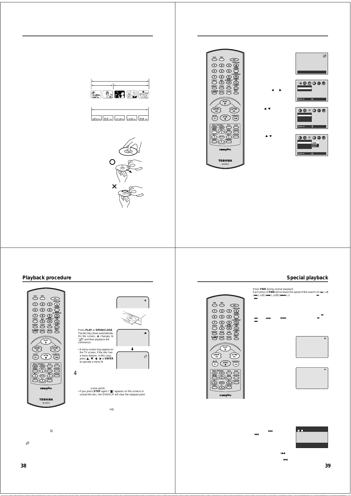
Disc
This unit applies to DVD discs from Region 2 only.
The loaded Disc (DVD, Video-CD, Audio-CD and MP3-CD) will be recognized automatically.
The suitable Disc-formats are: DVD, CD-R and CD-RW.
Some CD-R/RW discs may be incompatible.
This DVD/VCR uses the PAL color system. The NTSC-DVDs can be playback on PAL 60Hz.
Do not play DVD-ROM, DVD-Audio, CDV, CD-G or Photo CD to prevent accidental erasure of prerecorded material.
Some DVDs is played back with a Copy guard system. In case of a dubbing on video tape, strong disturbance may
occur. This is not a defect of this DVD/VCR.
Title
When two or more movies are recorded on a disc,
the disc is divided into two or more sections. Each
section is called a “TITLE”.
Chapter
The titles can be subdivided into many sections.
Each section is called a “CHAPTER”.
Track
An Audio CD can contain several items.
These are assigned to the tracks.
Removing Disc from Case
Be sure to hold the edge of disc. Do not touch the surface of the disc.
Pick up the disc gently from the case.
• Do not scratch the disc.
• Do not get dirt on the surface of the disc.
• Do not stick a label or adhesive tape on the disc.
• Do not drop or bend the disc.
Storing Disc
• Store the disc in the case to avoid risk of scratches, dirt or damage.
• Do not leave disc exposed to direct sunlight or in hot or humid places.
Cleaning Disc
Wipe the disc with a clean, dry cloth from centre to edge.
• Do not wipe the disc round.
• Do not use liquid or aerosol cleaners.
CHAPTER 1
TRACK 1 TRACK 2 TRACK 3 TRACK 4 TRACK 5
DVD DISC
TITLE1 TITLE2
CHAPTER 2 CHAPTER 2 CHAPTER 3CHAPTER 1
Audio-CD
CD
The setup language can be selected.
DVDVCR
OPEN/CLOSE
CLOCK
COUNTER
ANGLE
COUNTERRESET
AUDIO
SUBTITLE
AUXTV/VCR
AUDIOSELECT
ATR
PLAYMODE
ZOOM
E.A.M
MEMORY
TIMERREC
REW FWD
SLOW
INDEXÐ SKIPINDEX +
SETUP
VCRMENU
SETÐ
CANCEL
If the DVD/VCR does not operate
properly:
Static electricity, etc., may
affect the player's operation. Disconnect
the AC power cord once, then connect
it again.
REC/OTR
ENTER
SP/LP
DISPLAY
RETURN
CALL
PLAY
PAUSE/STILL
STOP
A-BRPT
TITLE
ZERORETURN
CH+
MENU
INSTANTSKIP
SET+
CHÐ
VIDEOPlus+
Setting setup language
Preparation:
• Turn ON the TV and set to the video input mode.
• When using an amplifier, switch on the amplifier.
DVD
Press
1
2
3
4
5
to select the DVD
mode. (The DVD indicator will
light.)
“No Disc” will appear on the
screen. (If a DVD disc has already loaded, the playback will
start automatically.)
SET UP
Press
in the stop mode.
The SETUP MENU of DVD will
appear on the screen.
Then press
“Language”.
Press / to select On-Screen
Language, then press
Press
language: English (English),
German (Deutsch) or French
(Français).
To make the SETUP screen disappear, press
RETURN
or
/ to select desired
).
to select
ENTER
.
No Disc
Picture
TV Shape 4:3LB
Video Out Select Video
Language
On-Screen LanguageENG
Disc Menu Language ENG
Audio Language ENG
Subtitle Language ENG
Language
On-Screen LanguageENG
Disc Menu Language ENG
Audio Language ENG
Subtitle Language ENG
C
B
A
: Select : Enter
C
B
A
: Select : Enter
C
B
A
English
Franais
Espaol
: Select : Enter
SET UP
(or
36
Playback procedure
Preparation:
• Turn ON the TV and set to the video input mode.
DVD
• Press
DVDVCR
OPEN/CLOSE
CLOCK
COUNTER
ANGLE
COUNTERRESET
AUDIO
SUBTITLE
AUXTV/VCR
AUDIOSELECT
ATR
PLAYMODE
ZOOM
E.A.M
MEMORY
TIMERREC
REW FWD
SLOW
INDEXÐ SKIPINDEX +
SETUP
VCRMENU
SETÐ
CANCEL
NOTES:
• If a non-compatible disc is loaded, "Please Check Disc", "Disc playback unauthorized Consult owners manual
for further information" or "Parental Lock" will appear on the TV screen according to the type of loaded disc. In
this case, check your disc again (See pages 36 and 46, 47).
• Some discs may take a minute or so to start playback.
• A “Prohibition” symbol
tried is not available on the disc, or the DVD/VCR can not access the feature at this time. This does not indicate
a problem with the DVD/VCR.
When you set a single-faced disc label downwards (ie. the wrong way up) and press
•
"
" will appear and remain on the screen for approx. 30 seconds and then it will change to "Please Check Disc".
• Some playback operations of DVDs may be intentionally fixed by software producers. Since this DVD/VCR plays
DVDs according to the disc contents the software producers designed, some playback features may not be
available. Also refer to the instructions supplied with the DVDs.
• When playing DTS-encoded Audio CDs, excessive noise will be heard from the analog stereo outputs. To avoid
possible damage to the audio system, the consumer should take proper precautions when the analog stereo
outputs of the DVD/VCR are connected to an amplification system.
SP/LP
DISPLAY
REC/OTR
RETURN
CALL
PLAY
PAUSE/STILL
STOP
A-BRPT
TITLE
ZERORETURN
CH+
MENU
INSTANTSKIP
SET+
ENTER
CHÐ
VIDEOPlus+
may appear at the upper right of the screen. This symbol means either the feature you
to select the DVD mode. (The DVD indicator will light)
OPEN/CLOSE
Press
1
The disc tray will open.
Place a disc onto the tray.
2
Hold the disc, position it with the
printed label side up, align it with
the guides, and place it in its
proper position.
Press
3
The disc tray closes automatically.
On the screen, changes to
“
” and then playback will
commence.
• A menu screen may appear on
the TV screen, if the disc has
a menu feature. In this case,
press , , , or ENTER
to operate a menu feature.
Press
4
• The DVD/VCR memorizes the stopped point, depending on
the disc. “To Return To The Last Scene Viewed, Press Play . To
Disable This Operation, Press STOP Again.” appears on the
screen for approx. 4 seconds. Press
(from the scene point).
• If you press
unload the disc, the DVD/VCR will clear the stopped point.
Then press
5
The disc tray opens.
Remove the disc and press
The disc tray closes automatically and DVD/VCR turns off.
PLAY
or
STOP
to end playback.
OPEN/CLOSE
.
OPEN/CLOSE
STOP
again (“
.
PLAY
to resume playback
” appears on the screen) or
.
(POWER)
,
.
PLAY
or OPEN/CLOSE,
38
Note: There may be a slight delay between pressing the button and the
function activation.
DVDVCR
OPEN/CLOSE
CLOCK
COUNTER
ANGLE
COUNTERRESET
AUDIO
SUBTITLE
AUXTV/VCR
AUDIOSELECT
ATR
PLAYMODE
ZOOM
MEMORY
E.A.M
SP/LP
REC/OTR
ENTER
DISPLAY
RETURN
CALL
PLAY
PAUSE/STILL
STOP
A-BRPT
TITLE
ZERORETURN
CH+
MENU
INSTANTSKIP
SET+
CHÐ
VIDEOPlus+
SKIP
TIMERREC
REW FWD
SLOW
INDEXÐ SKIPINDEX +
SETUP
VCRMENU
SETÐ
CANCEL
NOTES:
• The unit is capable of holding a still
video image or On screen display image
on your television screen indefinitely. If
you leave the still video image or On
screen display image displayed on your
TV for an extended period of time, you
risk permanent damage to your
television screen. Projection televisions
are very susceptible.
• Some titles may not display chapter
numbers.
• When you set “Title Stop” to “Off” (See
page 53), you can access chapter in
another title. If you go back to the
preceding title by pressing the
DVD/VCR locates the first chapter of the
title. When “Title Stop” is set to “On”.
you can access chapters only within the
current title.
Special playback
Fast Forward Playback
FWD
Press
during normal playback.
FWD
Each press of
(
(
• To resume normal playback, press
Review Playback
Press
Each press of
(
(
• To resume normal playback, press
Still Playback
Press
playback.
To resume normal playback, press
PLAY
Frame Advance
Press
back.
One frame is advanced each time
you press
To resume normal playback, press
PLAY
Slow-motion Playback
Press SLOW during
Each press of
x1/8.
• To resume normal playback, press
• To resume the still playback, press
Locating a chapter or track
Press
(
locate a chapter or track that you
want to watch.
Each time you press the button, a
“C (chapter)” number or “T (track)”
, the
number is skipped.
When you press SKIP (
of the current chapter or track.
When you press SKIP (
beginning of the preceding chapter or track.
will increase the speed of the search x2 (
), x30 ( ), x100 ( ). (in case of Audio-CD: x4 ( ) and x8
) are available)
REW
during normal playback.
REW
will increase the speed of the search x2 (
), x30 ( ), x100 ( ). (in case of Audio-CD: x4 ( ) and x8
) are available)
PAUSE/STILL
during normal
.
PAUSE/STILL
during still play-
PAUSE/STILL
.
.
normal playback or still playback.
SLOW
will change the speed of the slow x1/2, x1/4,
SKIP (
)
SKIP
Forward or
Reverse during playback to
)
), playback starts from the beginning
) twice, playback starts from the
PLAY
.
PLAY
.
PLAY
.
PAUSE/STILL
T C
11
37
), x8
), x8
.
39
Page 12

DVD Picture Signal Selection/Zooming
You can select the output signal of
DVD playback picture to the TV
screen as an VIDEO signal or a RGB
signal.
DVDVCR
OPEN/CLOSE
CLOCK
COUNTER
ANGLE
COUNTERRESET
AUDIO
SUBTITLE
AUXTV/VCR
AUDIOSELECT
ATR
PLAYMODE
ZOOM
E.A.M
MEMORY
TIMERREC
REW FWD
SLOW
INDEXÐ SKIPINDEX +
SETUP
VCRMENU
SETÐ
CANCEL
Notes:
• Picture Signal Selection is only
available for connecting with a 21 pin
Scart Cable.
• Depending on your TV, NTSC disc
may not playback correctly in colour. In
this case, it is recommended to select
the Picture Signal RGB on step 2.
• Only use RGB setting if your TV is
RGB compatible.
REC/OTR
CH+
ENTER
CHÐ
SP/LP
DISPLAY
RETURN
CALL
PLAY
PAUSE/STILL
STOP
A-BRPT
TITLE
ZERORETURN
MENU
INSTANTSKIP
SET+
VIDEOPlus+
40
Preparation:
• Turn ON the TV and set to the video input mode.
DVD
• Press
to select the DVD mode. (The DVD indicator will
light)
SET UP
Press
1
2
3
Notes:
• If you use the connection with S-Video cord, be sure to set the
“Video Out Select” at step 2 above to “Video”. If you select “RGB”,
the TV screen will be disturbed.
• If you selected “RGB” at step 2 above, press
VCR. (VCR indicator will appear on the display) Otherwise, the
TV screen will be disturbed when you select the channel with
TV’s CHANNEL UP/DOWN buttons.
in the stop
mode.
Press
or to select “Pic-
ENTER
.
or to select the
or to
ture”, then press
select “Video Out Select”.
Press
Press
desired picture signal, “Video”
or “RGB”.
To make SETUP screen disappear, press
Zooming
This unit will allow you to zoom in on the frame image. You
can then make selections by switching the position of the
frame.
ZOOM
Press
1
2
3
during playback.
The centre part of the image
will be zoomed in.
As you repeatedly press the
ENTER
ZOOM
or
“ZOOM” is selected, the magnification level changes. Variation of the levels includes
image reduction.
Press / or / to view a different part of the frame.
You may move the frame from the centre position to UP,
DOWN, LEFT or RIGHT direction.
• If you select “EXIT” and press the ENTER, you can turn off
the symbol mark, keeping the current magnification level.
• Press
of the picture.
While “
turn to a 1:1 view.
while
CANCEL
to restore the zoom point to the centre
ZOOM
” is selected, press
Picture
TV Shape 4:3LB
Video Out Select Video
: Select : Enter
Picture
TV Shape 4:3LB
Video Out Select Video
: Select : Enter
ZOOM
EXIT
Zoom Off
: Select : Change
ZOOM
C
B
A
C
B
A
Video
RGB
SET UP
.
TV/VCR
to select
repeatedly to re-
DVDVCR
OPEN/CLOSE
CLOCK
COUNTER
ANGLE
COUNTER RESET
AUDIO
SUBTITLE
AUXTV/VCR
AUDIO SELECT
ATR
PLAY MODE
ZOOM
MEMORY
E.A.M
SP/LP
REC/OTR
ENTER
DISPLAY
RETURN
CALL
PLAY
PAUSE/STILL
STOP
A-B RPT
TITLE
ZERO RETURN
CH +
MENU
INSTANT SKIP
SET +
CH –
VIDEO Plus+
TIMER REC
REW FWD
SLOW
INDEX – SKIP INDEX +
SET UP
VCR MENU
SET –
CANCEL
NOTES:
•
Some discs may not work with the
repeat operation.
•
In A-B repeat mode, subtitles near
point A or B may not appear.
•
During the A-B Repeat Playback the
ANGLE feature will not operate.
•
You may not be able to set A-B Repeat, depending on the scenes of the
DVD.
•
A-B repeat does not work with an interactive DVD and MP3-CD.
•
Random playback can not be combined with Repeat playback.
Repeat playback
Preparation:
• Turn ON the TV and set to the video input mode.
DVD
• Press
to select the DVD mode. (The DVD indicator will light)
REPEAT PLAYBACK
PLAY MODE
Press
1
“Title Repeat” or “All Repeat”. (In case of CD, select “Track
Repeat” or “ All Repeat” )
Chapter Repeat
During playback repeat playback will start automatically.
2
To start repeat playback during stop mode, press
about 5 seconds after you press
• To resume normal playback, press
until “Off” appears on the TV-screen.
A-B Repeat Playback
A-B repeat playback allows you to repeat material between two
selected points.
Press
1
The start point is selected.
Press
2
The end point is selected.
Playback starts at the point that
you selected. Playback stops at
the end point, returns to Point A
automatically, then starts again.
To resume normal playback,
press
“Repeat Off” appears on the screen.
repeatedly to select “Chapter Repeat”,
DVD
A-B RPT
during playback.
A-B RPT
again.
A-B RPT
again.
Track Repeat
PLAY MODE
PLAY MODE
A
-
A-B
CD
.
PLAY
within
repeatedly
41
Memory playback/Random playback
Preparation:
• Turn ON the TV and set to the video input mode.
DVD
• Press
to select the DVD mode. (The DVD indicator will light)
DVDVCR
AUXTV/VCR
ZOOM
MEMORY
TIMER REC
REC/OTR
PLAY
REW FWD
SLOW
STOP
INDEX – SKIP INDEX +
SET UP
CH +
VCR MENU
SET –
ENTER
CH –
CANCEL
AUDIO
AUDIO SELECT
E.A.M
RETURN
TITLE
MENU
SET +
VIDEO Plus+
OPEN/CLOSE
CLOCK
COUNTER
ANGLE
COUNTER RESET
SUBTITLE
ATR
PLAY MODE
SP/LP
DISPLAY
CALL
PAUSE/STILL
A-B RPT
ZERO RETURN
INSTANT SKIP
Memory playback
You can arrange the order of titles, chapters or tracks on the disc.
MEMORY
Press
1
Press / to
2
select “T” Title
number or “CT”
Chapter or Track
number. Use
number keys
Input the favorite
number.
• If you input a large number than the number that is recorded
• The input number into "T" for CD or MP3 is not effective.
Press or ENTER.
3
Set the “T” and
“CT” in the next
bar as In step 2.
• When you select another chapter In the same title, you do
• To cancel the programmed selection, press
Press
4
• To resume normal playback, press
.
to
on the disc, the bar will be skipped.
not need to select the title number.
PLAY
to start MEMORY playback.
Random playback
PLAY MODE
NOTES:
The memory
playback
•
when press STOP during memory
playback.
• Random playback can not be
combined with Repeat playback.
• You can program up to 30 selections
into the memory.
• Depending on the DVD, Chapter
Random operation may not work
during playback.
• You cannot use the random playback
with memory playback.
is cancelled
Press
1
or “Title Random”.(In case of CD, select Track Random)
Chapter Random
During playback random playback will start automatically.
2
To start random playback during stop mode, press
within about 5 seconds after you press the
• To resume normal playback, press
until “Off” appears on the TV-screen.
repeatedly to select “ Chapter Random”
DVD
42
In stop mode
1 T:- -CT:- -
-
2 T:- -CT:- -
-
3 T:- -CT:- -
-
4 T:- -CT:- -
-
5 T:- -CT:- -
-
6 T:- -CT:- -
-
7 T:- -CT:- -
-
Memory
: Select 0-9 : Input : Play
In stop mode
1 T:01 CT:002
2 T:
- -
CT:- -
-
3 T:- -CT:- -
-
4 T:- -CT:- -
-
5 T:- -CT:- -
-
6 T:- -CT:- -
-
7 T:- -CT:- -
-
Memory
: Select 0-9 : Input : Play
In stop mode
1 T:01 CT:002
2 T:02 CT:004
3 T:
- -
CT:- -
-
4 T:- -CT:- -
-
5 T:- -CT:- -
-
6 T:- -CT:- -
-
7 T:- -CT:- -
-
Memory
: Select 0-9 : Input : Play
1 T:- -CT:- -
Memory
1 T:01 CT:002
Memory
2 T:02 CT:004
Memory
CANCEL
CANCEL
Track Random
PLAY MODE
PLAY MODE
In playback
-
: Select 0-9 : Input : Play
In playback
: Select 0-9 : Input : Play
In playback
: Select 0-9 : Input : Play
.
CD
PLAY
repeatedly
MP3 Playback
This player can play back the MP3-data
which has been recorded on CD-R or CDRW. To produce the MP3-data, you need a
Windows-PC with CD-ROM drive and a MP3encoding Software (not supplied).
The Apple-HFS-System can not be played.
MP3 CD Information
Limitations on MP3 CD playback
• MP3 CD is the disc that is standardized by
ISO9660, its file name must include 3-digits
extension letters, “mp3”.
• The directory and file names of the MP3
CD must correspond to the ISO
standardized files.
• This unit can read 200 files per disc. If
one directory has more than 200 files, it
reads up to 200 files, the remaining files will
be omitted.
• As for multi-session disc, only the first
session can be played.
• If the CD has both audio tracks and MP3
files, only audio tracks are played.
• It may take more than one minute for this
unit to read MP3 files depending on its
structure.
• Music recorded by “Joliet Recording
Specification” can be played back, the file
name is displayed (within 8 letters) on the
screen. Long file names will be condensed.
• The music files recorded by “Hierarchical
File System” (HFS) cannot be played.
Limitations on display
The maximum number for display is 8
.
letters. Available letters for display are the
following: capital or small alphabets of A
through Z, numbers of 0 through 9, and _
(under score).
Notes on MP3 files
To play back MP3 CD in the recorded order ,
1.Use MP3 software that records data
alphabetically or numerically.
2. Name each file including a two-digit or three-
digit number (e.g. “01” “02” or “001” “002”).
3. Refrain from making too many sub-folders.
CAUTION:
• Some MP3 CDs can not be played back
depending on the recording conditions.
• The CD-R/RW that has no music data or
non-MP3 files can not be played back.
.
Preparation:
• Turn ON the TV and set to the video input mode.
• Press DVD to select the DVD mode. (The DVD indicator will
light)
Press OPEN/CLOSE.
1
The disc tray will open.
Place a disc onto the tray.
Press PLAY or OPEN/CLOSE.
2
The disc tray closes automatically.
On the TV-screen, “
reading file number will appear.
Then playback will commence.
• Reading will take as much time
as the number of file.
• Press STOP to end playback.
DISPLAY
Press
3
Then press
and press ENTER.
Press
4
ENTER. Track is selected and play commences.
•
• To remove track list, press CANCEL.
• Press
Press STOP to end playback.
5
• The unit records the stopped track.
• If you press STOP again or unload the disc, the unit will
Press OPEN/CLOSE.
6
The disc tray opens.
Remove the disc and press
The disc tray closes automatically and DVD/VCR turns off.
NOTES:
•
During MP3-Playback, you can not use SEARCH, A-B
Repeat functions.
•
You can use Repeat(Track or All), Memory and Random functions
for MP3 CD Playback.(See page 41 and 42)
.
/ to select
/ or / to select the desired track, then press
In case the folder includes more than 9 tracks, press
to display next track list.
/
to select “T” and press number keys to
input your desired track.
Press PLAY to resume playback (from the beginning of
track).
clear the stopped track.
” and then
MP3
11
T
MP3
T
1 000:23
: Select : Enter
MP3
T
1 000:23
1. \ CRYINI~1
2. \ DANGER~1
3. \ GITARREN
4. \ LILYWA~1
5. \ MERCYS~1
6. \ OBSESS~1
7. \ PINKPA~1
8. \ RUNNIN~1
: Select : Search
.
EAM
PCM
/
EAM
PCM
43
Page 13
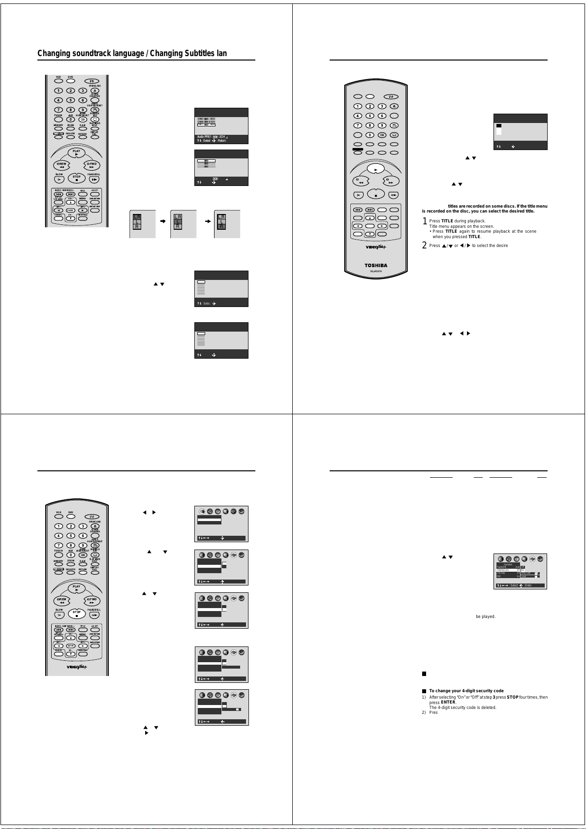
Changing soundtrack language / Changing Subtitles language
Preparation:
• Turn ON the TV and set to the video input mode.
DVD
• Press
DVDVCR
OPEN/CLOSE
CLOCK
COUNTER
ANGLE
COUNTERRESET
AUDIO
SUBTITLE
AUXTV/VCR
AUDIOSELECT
ATR
PLAYMODE
ZOOM
MEMORY
E.A.M
SP/LP
REC/OTR
RETURN
PLAY
PAUSE/STILL
STOP
TITLE
CH+
MENU
SET+
ENTER
CHÐ
VIDEOPlus+
several times, the
DISPLAY
CALL
A-BRPT
ZERORETURN
INSTANTSKIP
TIMERREC
REW FWD
SLOW
INDEXÐ SKIPINDEX +
SETUP
VCRMENU
SETÐ
CANCEL
NOTES:
• If the desired language is not heard after
AUDIO
pressing
language is not recorded on the disc.
• Changing soundtrack or subtitle
language is cancelled when you open the
disc tray or turn the power off. The initial
default language or available language
will be heard and seen if the disc is
played back again.
Depending on the DVD you may be
•
unable to turn on, turn off, or change the
subtitles, even if they are recorded on the
disc. While playing the DVD, the subtitle
may change while opening or closing the
disc tray, or while changing the title.
During some scenes, the subtitles may not
•
appear immediately after you select “On”.
• The abbreviation of the language
appears instead of the language name.
Refer to the list of languages and their
abbreviations. (See on page 57.)
to select the DVD mode. (The DVD indicator will light)
Changing soundtrack language
You can select the language when you play a multilingual disc.
AUDIO
Press
1
2
In case of VIDEO CD playback
Audio type changes as follows each time you press AUDIO.
Changing Subtitles language
You can select the language when playing back a disc recorded
with multi-lingual subtitles.
1
2
during playback.
The current soundtrack language
is displayed.
AUDIO
Press
repeatedly until
the desired language is selected.
The on-screen display will disappear after a few seconds.
• To turn off the soundtrack
setting display, press the
CANCEL
ENTER
or
button.
during
/ to select the
CANCEL
button.
repeatedly to
L.R
L
R
L.R
L
R
SUBTITLE
Press
playback.
Then press
desired language.
• To turn off the subtitle setting
display, press the
ENTER
or
• To turn the subtitles off, select
“Off”.
SUBTITLE
Press
turn Subtitles on or off.
ENG1 2CH
ENG2 5.1CH
FRE1 2CH
Audio:FRE1 2CH
: Select : Return
ENG1 2CH
ENG2 5.1CH
FRE1 2CH
Audio:ENG1 2CH
: Select : Return
Off
GER 1
DUT 1
SV 1
NO 1
- - -
Off
Subtitle:
: Select : Return
Off
GER 1
DUT 1
SV 1
NO 1
- - -
Off
Subtitle:
: Select : Return
2CH
2CH
L.R
L
R
44
Changing angles / Title selection / DVD menu
Preparation:
• Turn ON the TV and set to the video input mode.
DVD
• Press
to select the DVD mode. (The DVD indicator will light)
DVDVCR
OPEN/CLOSE
CLOCK
COUNTER
ANGLE
COUNTER RESET
AUDIO
SUBTITLE
AUXTV/VCR
AUDIO SELECT
ATR
PLAY MODE
ZOOM
E.A.M
MEMORY
TIMER REC
REW FWD
SLOW
INDEX – SKIP INDEX +
SET UP
VCR MENU
SET –
CANCEL
NOTE:
Depending on the DVD, you may not
be able to change the angles even if
multi-angles are recorded on the disc,
or you may be unable to select the title,
and a “title menu” may simply be called
a “menu” or “title” in the instructions
supplied with the disc.
REC/OTR
ENTER
SP/LP
DISPLAY
RETURN
CALL
PLAY
PAUSE/STILL
STOP
A-B RPT
TITLE
ZERO RETURN
CH +
MENU
INSTANT SKIP
SET +
CH –
VIDEO Plus+
Changing Angles
When playing back a disc recorded with multi-angle facility,
can change the angle that you are viewing the scene from.
ANGLE
Press
1
2
Title Selection
Two or more titles are recorded on some discs. If the title menu
is recorded on the disc, you can select the desired title.
1
2
3
DVD Menu
Some DVDs allow you to select the disc contents using the
menu.
When you play back these DVDs, you can select the subtitle
language and sound-track language,etc. using the DVD menu.
1
2
3
during playback.
The current angle will appear.
ANGLE
Press
selected.
• To turn off the angle number display, press the
• You can change the camera angle directly by pressing the
Press
Title menu appears on the screen.
• Press
or / repeatedly until the desired angle is
number keys
corresponding to its angle number instead of
using the
/ buttons.
TITLE
during playback.
TITLE
again to resume playback at the scene
when you pressed
TITLE
.
Press / or / to select the desired title.
ENTER
Press
The playback of the selected title will start.
Press
The DVD menu appears on the screen.
• Press
PLAY
or
.
MENU
during playback.
MENU
again to resume playback at
the scene when you pressed
Press / or / to select the desired item.
ENTER
Press
.
The menu continues to another screen. Repeat steps 2 and 3 to
set the item completely.
MENU
1
2
3
Angle :1
: Select : Return
.
CANCEL
you
.
45
Parental control
Some discs are specified not suitable
for children. Such discs can be
prevented from play back with the
unit.
DVDVCR
OPEN/CLOSE
CLOCK
COUNTER
ANGLE
COUNTERRESET
SUBTITLE
AUDIO
AUXTV/VCR
ATR
AUDIOSELECT
PLAYMODE
ZOOM
E.A.M
MEMORY
TIMERREC
REW FWD
SLOW
INDEXÐ SKIPINDEX +
SETUP
VCRMENU
SETÐ
CANCEL
NOTES:
•
If each setup (page 46~55) has been
completed, the unit can always be
worked under the same conditions
(especially with DVD discs).
Each setup will be retained in the
memory if you turn the power off.
•
Depending on the discs, the unit cannot limit playback.
•
Some discs may not be encoded with
specific rating level information though
its disc jacket says "adult". For those
discs, the age restriction will not work.
•
Do not forget the security code. If you
forget the security code, delete it. (See
step 7 on next page)
REC/OTR
ENTER
SP/LP
DISPLAY
RETURN
CALL
PLAY
PAUSE/STILL
STOP
A-BRPT
TITLE
ZERORETURN
CH+
MENU
INSTANTSKIP
SET+
CHÐ
VIDEOPlus+
46
Preparation:
• Turn ON the TV and set to the video input mode.
DVD
• Press
to select the DVD mode. (The DVD indicator will light)
Parental control setting
SET UP
Press
1
2
3
4
5
in the stop mode.
or to select “Opera-
Press
tion”.
Press or to select
“Parental Lock”, then press
ENTER
.
Press or to select Off or On.
Off: The parental lock feature
does not function.
ENTER
After pressing
follow step 4 and 6 below.
On: To activate the parental lock
feature or change the
setting, press
follow steps 4-6 below.
number keys
Press
4-digits security code then
ENTER
press
• If you input a wrong number,
CANCEL
press
• To return to the before step,
RETURN
press
Enter the code of a country/area
whose standards were used to
rate the DVD disc. (See the list
on the page 47)
Example:
Set to GB (UNITED
KINGDOM).
or to select “G” then
Press
press
to move to the right
character. Then select “B” same
as above. Then press
,
ENTER
and
to input a
.
.
.
ENTER
.
Picture
TV Shape 4:3LB
Video Out Select
Operation
Pause/Still AutoOnOff
Parental Lock Off
Title Stop Off
PBC On
Operation
Pause/Still Auto
Parental Lock Off
Title Stop Off
PBC On
Operation
Pause/Still Auto
Parental Lock Off
Title Stop Off
PBC On
Operation
Pause/Still AutoOnOff
Parental Lock Off
Title Stop Off
PBC On
C
B
A
: Select : Enter
C
B
A
: Select : Enter
C
B
A
Off
On
: Select : Enter
C
B
A
Off
On
Security Code
: Select : Enter
C
B
A
Area Code G B
: Select : Enter
Parental control
Country/Area Code
AUSTRALIA AU
BELGIUM BE
CANADA CA
CHINA CN
CHINA HONG KONG HK
DENMARK DK
FINLAND FI
FRANCE FR
GERMANY DE
INDONESIA ID
ITALY IT
JAPAN JP
MALAYSIA MY
Press / to select the paren-
6
tal lock level, then press
You cannot play DVD discs rated higher than the level you selected
unless you cancel the parental lock function.
For example, when you select level 7, discs rated higher than level
7 are locked out and cannot be played.
• Level 1:
DVD software for adults cannot be played back.
• Level 8:
All DVD software can be played back.
•
Select from the level 1 to level 8. The limitation will be more severe
as the level number is lower.
To make the SETUP screen disappear, press
----
7
To change the parental lock level
Follow steps 1- 6.
To change your 4-digit security code
1) After selecting “On” or “Off” at step 3 press
ENTER
press
.
The 4-digit security code is deleted.
Press number keys to create a new 4-digit security code at step 4.
2)
Country/Area Code
NETHERLANDS NL
NORWAY NO
PHILIPPINES PH
RUSSIAN FEDERATION RU
SINGAPORE SG
SPAIN ES
SWEDEN SE
SWITZERLAND CH
TAIWAN TW
THAILAND TH
UNITED KINGDOM GB
UNITED STATES US
ENTER
.
Operation
Pause/Still AutoOnOff
Parental Lock Off
Title Stop Off
PBC On
: Select : Enter
STOP
C
B
A
Area Code G B
Level 7
SET UP
.
four times, then
47
Page 14

Setting menu language
You can select the language of the
disc menu messages of DVDs.
DVDVCR
OPEN/CLOSE
CLOCK
COUNTER
ANGLE
COUNTERRESET
AUDIO
SUBTITLE
AUXTV/VCR
AUDIOSELECT
ATR
PLAYMODE
ZOOM
MEMORY
E.A.M
SP/LP
REC/OTR
ENTER
DISPLAY
RETURN
CALL
PLAY
PAUSE/STILL
STOP
A-BRPT
TITLE
ZERORETURN
CH+
MENU
INSTANTSKIP
SET+
CHÐ
VIDEOPlus+
TIMERREC
REW FWD
SLOW
INDEXÐ SKIPINDEX +
SETUP
VCRMENU
SETÐ
CANCEL
Preparation:
• Turn ON the TV and set to the video input mode.
DVD
• Press
to select the DVD mode. (The DVD indicator will light)
SET UP
Press
1
2
3
4
in the stop mode.
or to select “Lan-
Press
guage”.
Press
or to select “Disc
Menu Language”.
ENTER
Press
.
Press
or to select your
desired language, then press
ENTER
.
English, French, German
The selected language is the first-priority Menu language.
Others:
Other languages can be selected (See the Table of
languages on page 57).
Example:
Set to EN (ENGLISH).
Press
or to select “E” then press to move to
the right character. Then select “N” same as above.
ENTER
Then press
To make the SETUP screen disappear, press
.
Picture
TV Shape 4:3LB
Video Out Select Video
: Select : Enter
Language
On-Screen LanguageENG
Disc Menu Language ENG
Audio Language ENG
Subtitle Language ENG
: Select : Enter
Language
On-Screen LanguageENG
Disc Menu Language DE
Audio Language ENG
Subtitle Language ENG
: Select : Enter
SET UP
Setting audio soundtrack language
The same audio soundtrack language
can always be selected by your unit
even if you replace the disc or turn
C
B
A
C
B
A
English
Franais
Espaol
C
B
A
English
French
German
Others
Code D E
the power off.
MEMORY
TIMERREC
SLOW
INDEXÐ SKIPINDEX +
SETUP
VCRMENU
SETÐ
CANCEL
DVDVCR
COUNTERRESET
AUDIO
AUXTV/VCR
AUDIOSELECT
ZOOM
E.A.M
REC/OTR
RETURN
PLAY
REW FWD
PAUSE/STILL
STOP
TITLE
CH+
MENU
SET+
ENTER
CHÐ
VIDEOPlus+
OPEN/CLOSE
CLOCK
COUNTER
ANGLE
SUBTITLE
PLAYMODE
SP/LP
DISPLAY
CALL
A-BRPT
ZERORETURN
INSTANTSKIP
.
NOTES:
• If the selected language is not recorded on the disc, the original language will be heard.
• Some DVD discs may be played in a
different language than you selected.
A prior language may be programmed
on the disc.
Preparation:
• Turn ON the TV and set to the video input mode.
• Press DVD to select the DVD mode. (The DVD indicator will light)
Press SET UP in the stop mode.
1
Press or to select
“Language”.
or to select “Audio
Press
ATR
2
Language”.
Press ENTER.
3
Press
or to select your
desired Audio Language, then
press ENTER.
English, French, German
The language you have selected will play if it is recorded on
the disc.
Others: If you want to select another language, enter the lan-
guage code (See the Table of languages on page 57).
Example:
Set to EN (ENGLISH).
Press
or to select “E” then press to move to
the right character. Then select “N” same as above.
Then press ENTER.
To make the SETUP screen disappear, press SET UP.
4
Picture
TV Shape 4:3LB
Video Out Select Video
: Select : Enter
Language
On-Screen LanguageENG
Disc Menu Language ENG
Audio Language ENG
Subtitle Language ENG
: Select : Enter
Language
On-Screen LanguageENG
Disc Menu Language ENG
Audio Language DE
Subtitle Language ENG
: Select : Enter
C
B
A
C
B
A
C
B
A
English
French
German
Others
Code D E
48
Setting subtitle language
The same subtitle language can
always be selected even if you replace
the disc or turn the power off.
Preparation:
• Turn ON the TV and set to the video input mode.
• Press
1
DVDVCR
OPEN/CLOSE
CLOCK
COUNTER
ANGLE
COUNTERRESET
AUDIO
SUBTITLE
AUXTV/VCR
AUDIOSELECT
ATR
PLAYMODE
ZOOM
MEMORY
E.A.M
SP/LP
REC/OTR
ENTER
DISPLAY
RETURN
CALL
PLAY
PAUSE/STILL
STOP
A-BRPT
TITLE
ZERORETURN
CH+
MENU
INSTANTSKIP
SET+
CHÐ
VIDEOPlus+
TIMERREC
REW FWD
SLOW
INDEXÐ SKIPINDEX +
SETUP
VCRMENU
SETÐ
CANCEL
NOTES:
• If the selected language is not recorded
on the disc, the first-priority language is
selected.
• Some DVD discs may be set to display
subtitles in a different language than you
selected. A prior subtitle language may
be programmed on the disc.
50
2
3
4
DVD
to select the DVD mode. (The DVD indicator will light)
SET UP
Press
in the stop mode.
or to select
Press
“Language”.
or to select “Subtitle
Press
Language”.
ENTER
Press
.
or to select your
Press
desired language, then press
ENTER
.
English, French, German
The subtitle is displayed with the selected language if it is
recorded on the disc.
No Subtitle:
Subtitles do not appear.
Others:
If you want to select another language, enter the
language code (See the Table of languages on
page 57).
Example:
Set to EN (ENGLISH).
or to select “E” then press
Press
to the right character. Then select “N” same as above.
ENTER
Then press
.
To make the SETUP screen disappear, press
B
A
Picture
TV Shape 4:3LB
Video Out Select Video
: Select : Enter
A
Language
On-Screen LanguageENG
Disc Menu Language ENG
Audio Language ENG
Subtitle Language ENG
: Select : Enter
B
A
Language
On-Screen LanguageENG
Disc Menu Language ENG
Audio Language ENG
Subtitle Language AA
: Select : Enter
SET UP
C
C
B
C
English
French
German
No Subtitle
Others
Code A A
PLAY
to move
.
Setting the aspect ratio of TV screen / Setting on Screen display
You can select the aspect ratio for
your TV.
DVDVCR
OPEN/CLOSE
CLOCK
COUNTER
ANGLE
COUNTERRESET
AUDIO
SUBTITLE
AUXTV/VCR
AUDIOSELECT
ATR
PLAYMODE
ZOOM
MEMORY
E.A.M
SP/LP
REC/OTR
ENTER
DISPLAY
RETURN
CALL
PLAY
PAUSE/STILL
STOP
A-BRPT
TITLE
ZERORETURN
CH+
MENU
INSTANTSKIP
SET+
CHÐ
VIDEOPlus+
TIMERREC
REW FWD
SLOW
INDEXÐ SKIPINDEX +
SETUP
VCRMENU
SETÐ
CANCEL
NOTES:
• The displayable picture size is preset on
the DVD video disc. Therefore, the
playback picture of some DVD video
discs may not conform to the picture size
you select.
• When you play DVD video discs recorded in the 4:3 picture size only, the
playback picture always appears in the
4:3 picture size regardless of the TV
shape setting.
• If you select “16:9 widescreen” and you
own a 4:3 TV set, the DVD playback
picture will be horizontally distorted during playback. Images will appear to be
horizontally compressed. Always be
sure that your TV shape conforms to the
actual TV in use.
Preparation:
• Turn ON the TV and set to the video input mode.
DVD
• Press
to select the DVD mode. (The DVD indicator will light)
Setting the aspect ratio of TV screen
SET UP
Press
1
2
3
in the stop mode.
or to select
Press
“Picture”, then press
to select “TV shape”.
ENTER
Press
Press
desired screen type.
You have the following screen sizes to choose from:
4:3 Letterbox:
Select when a standard 4:3 TV is connected.
Displays theatrical images with masking bars above and below
the picture.
4:3 Normal:
Select when a standard 4:3 TV is connected.
Displays pictures cropped to fill your TV screen. Either or both
sides of the picture are cut off.
16:9 Widescreen:
Select this mode when connecting to a wide-screen TV.
A wide screen picture is displayed full size.
or
.
or to select your
To make the SETUP screen disappear, press
Picture
TV Shape 4:3LB
Video Out Select Video
: Select : Enter
Picture
TV Shape 4:3LB
Video Out Select Video
: Select : Enter
C
B
A
C
B
A
SET UP
Setting on Screen display
SET UP
Press
1
2
3
4
in the stop mode.
Press
or to select “Display”
Press
or to select “On-
Screen Displays”.
ENTER
Press
.
Press
or to select “On” or
“Off”.
On:
Operational modes (e.g.
”, “ ”) appear when you
“
press the buttons (factory
setting).
Off:
Operational modes (e.g. “
you press any buttons.
To make the SETUP screen disappear, press
C
B
A
Display
On-Screen DisplaysOn
Background Picture
Screen Saver On
: Select : Enter
C
B
A
Display
On-Screen DisplaysOff
Background Picture
Screen Saver On
: Select : Enter
”, “ ”) do not appear when
SET UP
4:3 Letterbox
4:3 Normal
16:9 Widescreen
.
Off
On
.
49
51
Page 15

Setting Audio
CLOCK
DVDVCR
OPEN/CLOSE
CLOCK
COUNTER
ANGLE
COUNTERRESET
AUDIO
SUBTITLE
AUXTV/VCR
AUDIOSELECT
ATR
PLAYMODE
ZOOM
MEMORY
E.A.M
SP/LP
REC/OTR
ENTER
DISPLAY
RETURN
CALL
PLAY
FWD
PAUSE/STILL
STOP
A-BRPT
TITLE
ZERORETURN
CH+
MENU
INSTANTSKIP
SET+
CHÐ
VIDEOPlus+
TIMERREC
REW
SLOW
INDEXÐ SKIPINDEX +
SETUP
VCRMENU
SETÐ
CANCEL
NOTES:
• The Dynamic Range Control function
works only during playback of Dolby
Digital recorded discs.
• The level of Dynamic Range Control
may differ depending on the DVD video
disc.
• The vocal output feature is used during
playback of Dolby Digital (multi-channel)
recorded DVD KARAOKE discs. This
feature allows you to turn off vocal audio
tracks, or restore them for background
accompaniment.
• When playing KARAOKE, connect the
appropriate audio equipment such as an
amplifier to the DVD player.
52
Preparation:
• Turn ON the TV and set to the video input mode.
DVD
• Press
to select the DVD mode. (The DVD indicator will light)
Audio Out Select
Select the output sound format corresponding to your system connection.
For details of sound recording systems, see on page 55.
Press SET UP in the stop mode.
1
or to select “Audio”.
Press
Press or to select “Audio Out
2
Select”, then press ENTER. Press
to select your desired output sound.
Bitstream: Select when connected to an amplifier equipped with a Dolby
Digital, DTS, MPEG1 or MPEG2 decoder. The DVD/VCR outputs
digital audio information in the bitstream format when you play a
DVD video disc recorded on the Dolby Digital, DTS, MPEG1 or
MPEG2 recording system.
Analog 2ch: Select when connected to a TV, Dolby Pro Logic or stereo
via the analog audio jacks.
PCM: Select when connected to a 2 channel digital stereo amplifier.
The DVD/VCR outputs sounds in the PCM 2ch format when you
play a DVD video disc recorded on the Dolby Digital.
MPEG2 recording system.
3
To make the SETUP screen disappear, press
Dynamic Range Control
Turn on or off a function that makes faint sounds easier to hear
even if you lower the volume during late hours playback.
Press SET UP in the stop mode.
1
or to select “Audio”.
Press
Press or to select “Dynamic
2
Range Control”, then press ENTER.
or to select “On” or “Off”.
Press
Off: Full dynamic range is maintained.
On: Dynamic range is reduced.
To make the SETUP screen disappear,
3
SET UP
press
Karaoke Vocal
Turn on or off the vocal output during DVD KARAOKE disc
playback.
1
2
3
.
SET UP
Press
in the stop mode.
or to select “Audio”.
Press
Press or to select “Karaoke
Vocal”, then press
Press
Off: The primary vocal is not output.
On: The primary vocal is output when
To make the SETUP screen disappear, press
ENTER.
or to select “On” or “Off”.
it is recorded on the disc.
or
C
B
A
Audio
Audio Out Select Bitstream
Dynamic Range Control
On
Karaoke Vocal On
: Select : Enter
SET UP
C
B
A
Audio
Audio Out Select Bitstream
Dynamic Range Control
On
Karaoke Vocal Off
: Select : Enter
C
B
A
Audio
Audio Out Select BitstreamOnOff
Dynamic Range Control
On
Karaoke Vocal Off
: Select : Enter
SET UP
Bitstream
Analog 2ch
PCM
system
MPEG1 or
.
Off
On
.
Preparation:
• Turn ON the TV and set to the video input mode.
DVD
• Press
to select the DVD mode. (The DVD
indicator will light)
Pause/Still
Select the resolution of still pictures.
SET UP
Press
1
2
3
Title Stop
Turn on or off a feature that automatically stops
playback after a title has been viewed.
1
2
3
in the
stop mode.
or to
Press
select “Operation”.
Press or to
select “Pause/Still”,
ENTER
then press
Press
select “Auto” or
“Frame”, then press
ENTER
Auto: For normal use. Still and fast motion images
Frame:
.
or to
.
can be paused.
The resolution of still pictures is improved,
so that you can make a motionless picture
clearer when you pause it.
To make the SETUP screen disappear, press SET UP.
SET UP
Press
in the
stop mode.
Press or to select “Operation”.
Press or to
select “Title Stop”,
ENTER
then press
Press
select “On” or “Off”,
then press
Off:
On:
To make the SETUP screen disappear,
press
.
or to
ENTER
.
The DVD/VCR continues after playback of
a title is completed.
The DVD/VCR stops after playback of a title
is completed.
SET UP
.
Picture
TV Shape 4:3LB
Video Out Select Video
: Select : Enter
Operation
Pause/Still Auto
Parental Lock Off
Title Stop Off
PBC On
: Select : Enter
Picture
TV Shape 4:3LB
Video Out Select Video
: Select : Enter
Operation
Pause/Still Auto
Parental Lock Off
Title Stop Off
PBC On
: Select : Enter
C
B
A
C
B
A
Auto
Frame
C
B
A
C
B
A
Off
On
Setting Operation
PBC
SET UP
Press
1
2
3
in
the stop mode.
or to
Press
select “Operation”.
Press or to select “PBC”, then press
Press
or to select “On” or “Off”, then press
ENTER
.
Off:
When playing a VIDEO CD without using
the menu.
On:
To use the menu when playing a PBCfeatured VIDEO CD.
To make the SET UP screen disappear, press
UP
.
Picture
TV Shape 4:3LB
Video Out Select Video
: Select : Enter
Operation
Pause/Still Auto
Parental Lock Off
Title Stop Off
PBC On
: Select : Enter
C
B
A
ENTER
.
C
B
A
Off
On
SET
53
Selecting the sound enhancement (E.A.M.)/Setting Background/
Setting Screen Saver
Preparation:
• Turn ON the TV and set to the video input mode.
DVD
• Press
to select the DVD mode. (The DVD
indicator will light)
Selecting the sound enhancement (E.A.M.*)
You can easily switch a preferred audio enhancement.
*E.A.M.: Enhanced Audio Mode
E.A.M
Press
1
2
Notes:
• Actual effects to sounds may vary depending on the speaker
• Actual effects to sounds may vary depending on the disc.
• When the DVD/VCR is connected to an amplifier equipped
• Selecting “Dialogue” disables “Dynamic Range Control”
• During MP3 playback, the sound enhancement is not
.
Select the sound enhancement by pressing / .
Each time you press the button, the sound enhancement changes.
Normal:
Normal sound.
3D:
To obtain expansive virtual surround sound
effects from just two speakers.
Dialogue:
To control critical centre channel information
to make dialogue more intelligible (only
when playing a DVD video disc recorded on
the Dolby Digital recording system).
To use this enhancement on sounds output
•
from the BITSTREAM/PCM jack, be sure to
set “Audio Out Select” to “PCM.” (see page 55).
To exit the audio enhancement selection
CANCEL.
system. Make selection according to your preference.
with Dolby Pro Logic Surround, select “Normal”.
Otherwise, Dolby Pro Logic Surround may function
differently than usual.
function (see page 52).
effective.
®
3-Dimensional Sound Processing provided by
Spatializer
Desper Products. Inc.
Certain audio features of this product manufactured under
a license from Desper Products, Inc., Spatializer
circle-in-square device are trademarks owned by Desper
Products, Inc.
Setting Background
Select the background color or background picture.
SET UP
Press
1
2
3
Setting Screen Saver (DVD only)
To turn the screen saver on or off.
1
Press
2
®
and the
3
in the
stop mode.
or to se-
Press
lect “Display”.
Press or to
select “Background”, then press
ENTER
. Press
or to select your
desired background, then press
ENTER
.
Blue: Blue background.
Gray: Gray background.
Picture: Use the picture which appears when you
turn on the DVD/VCR as a background.
Jacket: Use the jacket picture included on some
discs as a background. If it is not included,
a gray background will be substituted.
To make the SETUP screen disappear, press
UP
.
SET UP
Press
in the
stop mode.
or to
Press
select “Display”.
Press or to
select “Screen
Saver”, then press
ENTER
.
Press
or to
select “On” or “Off”,
ENTER
then press
Off: The screen saver is disengaged.
On: The screen saver operates in 10
minutes after you press
STILL
.
To make the SETUP screen disappear, press
UP
.
.
Picture
TV Shape 4:3LB
Video Out Select Video
: Select : Enter
Display
On-ScreenDisplay
On
Background Picture
ScreenSaver On
: Select : Enter
Picture
TV Shape 4:3LB
Video Out Select Video
: Select : Enter
Display
On-Screen Display
On
Background Picture
Screen Saver On
: Select : Enter
PAUSE/
C
B
A
C
B
A
Blue
Gray
Picture
Jacket
C
B
A
C
B
A
Off
On
54
SET
SET
Setting initial setup/output sound conversion table
You can install the initial system
setting.
MEMORY
TIMERREC
REW FWD
SLOW
INDEXÐ SKIPINDEX +
SETUP
VCRMENU
SETÐ
CANCEL
Output sound conversion table
You can select the output sound format corresponding to your system connection (see page 52).
Discs
DVD video
Linear PCM
discs
Linear PCM 44.1 kHz/16 bit
CDs
COUNTERRESET
AUDIO
AUXTV/VCR
AUDIOSELECT
ZOOM
E.A.M
REC/OTR
RETURN
PLAY
PAUSE/STILL
STOP
TITLE
CH+
MENU
SET+
ENTER
CHÐ
VIDEOPlus+
Recording system
Dolby Digital
48 kHz/16 bit
48 kHz/20 bit
48 kHz/24 bit
96 kHz/16 bit
96 kHz/20 bit
96 kHz/24 bit
DTS
MPEG1, MPEG2
DTS
COUNTER
ANGLE
SUBTITLE
ATR
PLAYMODE
SP/LP
DISPLAY
CALL
A-BRPT
ZERORETURN
INSTANTSKIP
Preparation:
• Turn ON the TV and set to the video input mode.
DVD
• Press
to select the DVD mode. (The DVD indicator will light)
Setting initial setup
SET UP
Press
1
2
3
in the stop mode.
or to select “Initial
Press
Setup”.
ENTER
Press
, then press or
to select “On-Screen
Language”, “TV Shape” or
“Audio Out Select”.
On-Screen Language: See on page 37.
TV Shape: See on page 51.
Audio Out Select: See on page 52.
To make the SETUP screen disappear, press
(sampling frequency/quantization bit)
Bitstream Analog 2ch PCM
DIGITAL AUDIO
ANALOG AUDIO
DIGITAL AUDIO
OUT jack
Bitstream
48 kHz/16 bit
48 kHz/16 bit
48 kHz/16 bit
48 kHz/16 bit
48 kHz/16 bit
48 kHz/16 bit
Bitstream
Bitstream
44.1 kHz/16 bit
Bitstream
OUT jack
48 kHz/20 bit
48 kHz/16 bit
48 kHz/20 bit
48 kHz/24 bit
48 kHz/16 bit
48 kHz/20 bit
48 kHz/24 bit
—
48 kHz/16 bit
44.1 kHz/16 bit
(Noise)
ANALOG AUDIO
OUT jack
OUT jack
48 kHz/20 bit
Bitstream
48 kHz/16 bit
48 kHz/16 bit
48 kHz/16 bit
48 kHz/20 bit
48 kHz/16 bit
48 kHz/24 bit
96 kHz/16 bit
—
96 kHz/20 bit
—
96 kHz/24 bit
—
Bitstream
Bitstream
44.1 kHz/16 bit 44.1 kHz/16 bit 44.1 kHz/16 bit
Bitstream
——
48 kHz/16 bit
(Noise)
C
B
A
Picture
TV Shape 4:3LB
Video Out Select Video
: Select : Enter
C
B
A
Initial Setup
On-Screen Language ENG
TV Shape 4:3LB
Audio Out Select Bitstream
: Select : Enter
English
Franais
Deutsch
Espaol
SET UP
DIGITAL AUDIO
ANALOG AUDIO
OUT jack
OUT jack
48 kHz/20 bit
48 kHz/16 bit
48 kHz/16 bit
48 kHz/16 bit
48 kHz/16 bit
48 kHz/20 bit
48 kHz/16 bit
48 kHz/24 bit
48 kHz/16 bit
48 kHz/16 bit
48 kHz/16 bit
48 kHz/20 bit
48 kHz/16 bit
48 kHz/24 bit
48 kHz/16 bit—48 kHz/16 bit
44.1 kHz/16 bit
Bitstream
(Noise)
.
55
Page 16
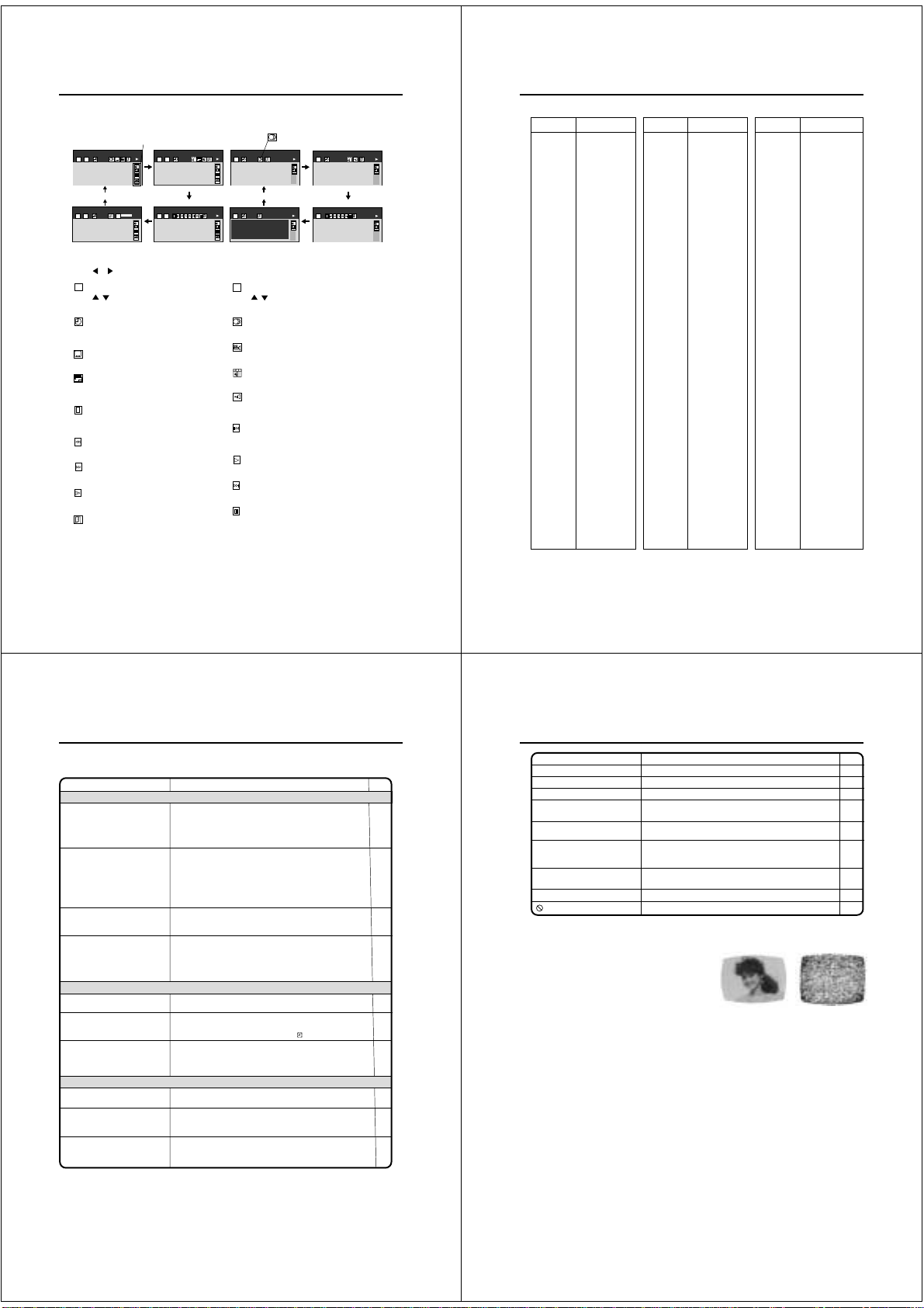
Status display of Disc
You can view information on the operation status and access and settings.
With each press of
1
DVD
T
2
T
2
Press or to select the desired symbol mark, then press
2
T
Press
track, then press ENTER.
Press
then press ENTER.
See page 44.
ZOOM
See page 40.
See page 38.
See Page 39.
See page 39.
See page 39.
CD TEXT
Displays CD text data if included on the audio
CDs. (Some letters may not be displayed
properly depending on the disc.)
DISPLAY
, the status of the disc will appear on the screen and change as follows.
Symbol mark of the feature
you selected is displayed.
ZOOM
T C
C
3 0:08:16
2 3 -0:21:28
EAM
2CH
ZOOM
X
1
C
OFF
BIT
RATE
C
3 0:08:16
9.2Mbps
T C
2 3
EAM
2CH
ZOOM
X
1
C
: Title number (Track number)
/ or number keys to locate a title or
: Elapsed (remaining) time of the current title
number keys to locate a desired Location,
: Subtitle setting
: To zoom a picture
: To stop playback
: Fast reverse playback
: Fast forward playback
: To begin slow motion playback
: To turn off the display
Audio/
Video CD
T
1
00:30
EAM
EAM
2CH
ZOOM
X
1
C
OFF
T
1 01:14
EAM
-----
CD TEXT
-----
Disc Title:
2CH
No Text
ZOOM
Track Title:
X
1
No Text
C
(Audio CD only)
ENTER
.
: Chapter number
C
Press
/ or number keys to locate a Chapter,
then press ENTER.
Audio setting
See page 44.
: Angle setting
See page 45.
: E.A.M. (Enhanced Audio Mode)
See page 54.
: Audio Out Select setting
BST: Bitstream 2CH:Analog 2ch PCM:PCM
See page 52.
: Playback starts from the beginning of the
current chapter or track.
See page 39.
: To start playback
See page 38.
: To locate succeeding chapters or tracks.
See page 39.
: To pause playback
See page 39.
Data transfer rate (Mbit/s)
Amount of picture, sound and subtitle data in the DVD
video disc transferred per second.
The larger the value is, the more data processed, but
this does not necessarily insure better picture quality.
56
mark is only for
Video CD.
EAM
EAM
PCM
EAM
PCM
Table of languages
Enter the appropriate code for the initial settings"Menu", "Audio" and/or "Subtitle" (see pages 48~50).
–––
CHI (ZH)
DUT (NL)
ENG (EN)
FRE (FR)
GER (DE)
ITA (IT)
JPN (JA)
KOR (KO)
MAY (MS)
SPA (ES)
AA
AB
AF
AM
AR
AS
AY
AZ
BA
BE
BG
BH
BI
BN
BO
BR
CA
CO
CS
CY
DA
DZ
EL
EO
ET
EU
FA
FI
FJ
FO
FY
GA
GD
GL
Language
No alternate
language
Chinese
Dutch
English
French
German
ltalian
Japanese
Korean
Malay
Spanish
Afar
Abkhazian
Afrikaans
Amharic
Arabic
Assamese
Aymara
Azerbaijani
Bashkir
Belorussian
Bulgarian
Bihari
Bislama
Bengali, Bangla
Tibetan
Breton
Catalan
Corsican
Czech
Welsh
Danish
Bhutani
Greek
Esperanto
Estonian
Basque
Persian
Finnish
Fiji
Faroese
Frisian
Irish
Scottish Gaelic
Galician
Abbreviation
GN
GU
HA
HI
HR
HU
HY
IA
IE
IK
IN
IS
IW
JI
JW
KA
KK
KL
KM
KN
KS
KU
KY
LA
LN
LO
LT
LV
MG
MI
MK
ML
MN
MO
MR
MT
MY
NA
NE
NO
OC
OM
OR
PA
PL
PS
Language
Guarani
Gujarati
Hausa
Hindi
Croatian
Hungarian
Armenian
Interlingua
Interlingue
Inupiak
Indonesian
Icelandic
Hebrew
Yiddish
Javanese
Georgian
Kazakh
Greenlandic
Cambodian
Kannada
Kashmiri
Kurdish
Kirghiz
Latin
Lingala
Laotian
Lithuanian
Latvian, Lettish
Malagasy
Maori
Macedonian
Malayalam
Mongolian
Moldavian
Marathi
Maltese
Burmese
Nauru
Nepali
Norwegian
Occitan
(Afan) Oromo
Oriya
Panjabi
Polish
Pashto, Pushto
Abbreviation
PT
QU
RM
RN
RO
RU
RW
SA
SD
SG
SH
SI
SK
SL
SM
SN
SO
SQ
SR
SS
ST
SU
SV
SW
TA
TE
TG
TH
TI
TK
TL
TN
TO
TR
TS
TT
TW
UK
UR
UZ
VI
VO
WO
XH
YO
ZU
Language
Portuguese
Quechua
Rhaeto-Romance
Kirundi
Rumanian
Russian
Kinyarwanda
Sanskrit
Sindhi
Sango
Serbo-Croatian
Singhalese
Slovak
Slovenian
Samoan
Shona
Somali
Albanian
Serbian
Siswati
Sesotho
Sundanese
Swedish
Swahili
Tamil
Telugu
Tajik
Thai
Tigrinya
Turkmen
Tagalog
Setswana
Tongan
Turkish
Tsonga
Tatar
Twi
Ukrainian
Urdu
Uzbek
Vietnamese
Volapük
Wolof
Xhosa
Yoruba
Zulu
Abbreviation
EPM
EAM
T
1
-03:38
EAM
EAM
PCM
T
1
EAM
PCM
57
Problems and troubleshooting
Use the following check list for troubleshooting when you have problems with your unit. Consult your local
dealer or service outlet if problems persist.
Be sure all connections are properly made when using with other units.
SYMPTOMS POSSIBLE SOLUTIONS
DVD/VCR
DVD/VCR does not operate.
No picture.
No sound.
The remote control does not
function.
VCR
TV recording does not work.
Timer recording does not work.
Noise bars on screen.
DVD
Display is not shown in your
language.
Playback doesn’t start.
Stopping playback, slow-motion
play, repeat play, or memory play,
etc. cannot be performed.
•Make sure the power cord is plugged in.
•Try another AC outlet.
•Power is off, check fuse or circuit breaker.
•Unplug unit, then plug it back in.
•Select the DVD or VCR mode before operating.
Antenna connection is not correct or antenna cable is disconnected.
•
• The video channel is not in the correct position or the TV is not
set to the video channel.
• Check the unit is connected correctly.
• The video input selector of the TV is not set to VIDEO. Set to
VIDEO (or equivalent).
• Channel is set to the external mode.
• Check the unit is connected correctly.
• Check the input selector of the amplifier is set properly.
• The unit is in the Special playback mode.
• Aim the remote control at the remote sensor.
• Operate within Approx. 5 Meters or reduce the light in the room.
• Clear the path of the beam.
• The batteries are weak. Replace the batteries.
• Check the batteries are inserted correctly.
•The erase prevention tab of the video cassette is broken off.
•The unit is in the external input mode.
• The time is not set correctly.
• The recording start/end time is not set correctly.
• The TIMER REC has not been pressed (
• Tracking adjustment beyond range of automatic tracking circuit.
Try Manual tracking adjustment.
• Video heads are dirty.
• The tape is worn or damaged.
is not lit).
•Select proper language in the menu options.
• No disc is inserted.
• The disc may be dirty. Clean up the disc.
• The unit cannot play DVD-ROMs, etc.
• Some discs may not do some of the functions.
PAGE
14,37
10
13
10~12
10~12
20,39
18
15
29
30
20
59
37
38
36
36
Problems and troubleshooting / Video head cleaning
SYMPTOMS POSSIBLE SOLUTIONS P AGE
No 4:3 (16:9) picture • The setup does not match your TV.
No on-screen display • Select Display On.
No surround sound • The setup does not match your stereo system.
–
–
–
–
–
–
The unit or remote operation key
is not functioning.
Playback does not start when the
title is selected.
Audio soundtrack and/or subtitle
language is not changed when
you play back a DVD.
No subtitle
Angle cannot be changed. • Multi-angles are not recorded on the DVD disc.
appears on the screen.
• Turn off the unit and unplug the AC power cord for several
minutes, then replug it.
• Check the Parental control setting.
• Multilingual language is not recorded on the DVD disc.
• Some discs have no subtitles.
• Subtitles are cleared. Press SUB TITLE.
• The function is prohibited with the unit or the disc.
–
Video head cleaning
Video head clogging
9
–
The video heads are the means by which the DVD/VCR reads
the picture from the tape during playback. In the unlikely event
that the heads become dirty enough to be clogged, no picture will be played back. This can easily be determined if,
during playback of a known good tape, there is good sound,
but no picture (picture is extremely snowy). If this is the case,
have the DVD/VCR checked by qualified service personnel.
NOTES:
DO NOT ATTEMPT TO CLEAN THE VIDEO HEADS OR SERVICE THE UNIT BY REMOVING THE
•
REAR COVER.
Video heads may eventually wear out and should be replaced when they fail to produce clear pictures.
•
To help prevent video head clogging, use only good quality VHS tapes. Discard worn out tapes.
•
Good Picture Snowy Picture
–
49,50
51
51
12
14
46
50
44
45
–
58
59
Page 17

IMPORTANT WARNING
CAUTION:
DVD PLAYER IS A CLASS 1 LASER PRODUCT. HOWEVER THIS PLAYER USES A VISIBLE LASER
BEAM WHICH COULD CAUSE HAZARDOUS RADIATION EXPOSURE IF DIRECTED. BE SURE TO
OPERATE THE PLAYER CORRECTLY AS INSTRUCTED.
THE FOLLOWING CAUTION LABEL IS LOCATED ON THE REAR PANEL OF THE PLAYER.
CLASS 1
LASER PRODUCT
(Printed on the Rear Panel)
WHEN THIS PLAYER IS PLUGGED TO THE WALL OUTLET, DO NOT PLACE YOUR EYES CLOSE
TO THE OPENING OF THE DISC TRAY AND OTHER OPENINGS TO LOOK INTO THE INSIDE OF
THIS PLAYER.
USE OF CONTROLS OR ADJUSTMENTS OR PERFORMANCE OF PROCEDURES OTHER THAN
THOSE SPECIFIED HEREIN MAY RESULT IN HAZARDOUS RADIATION EXPOSURE.
DO NOT OPEN COVERS AND DO NOT REPAIR YOURSELF. REFER SERVICING TO QUALIFIED
PERSONNEL.
SERVICING NOTICES ON CHECKING
1. KEEP THE NOTICES 3. PUT PARTS AND WIRES IN THE
As for the places which need special attentions,
they are indicated with the labels or seals on the
cabinet, chassis and parts. Make sure to keep the
indications and notices in the operation manual.
2. USE THE DESIGNATED PARTS
The parts in this equipment have the specific
characters of incombustibility and withstand
voltage for safety. Therefore, the part which is
replaced should be used the part which has
the same character.
Especially as to the important parts for safety
which is indicated in the circuit diagram or the
table of parts as a mark, the designated
parts must be used.
ORIGINAL POSITION AFTER
ASSEMBLING OR WIRING
There are parts which use the insulation
material such as a tube or tape for safety, or
which are assembled in the condition that
these do not contact with the printed board.
The inside wiring is designed not to get closer
to the pyrogenic parts and high voltage parts.
Therefore, put these parts in the original
positions.
PERFORM A SAFETY CHECK AFTER
4.
SERVICING
Confirm that the screws, parts and wiring which
were removed in order to service are put in the
original positions, or whether there are the
portions which are deteriorated around the
serviced places serviced or not. Check the
insulation between the antenna terminal or
external metal and the AC cord plug blades.
And be sure the safety of that.
HOW TO ORDER PARTS
Please include the following informations when you order parts. (Particularly the VERSION LETTER.)
1. MODEL NUMBER and VERSION LETTER
The MODEL NUMBER can be found on the back of each product and the VERSION LETTER can be
found at the end of the SERIAL NUMBER.
2. PART NO. and DESCRIPTION
You can find it in your SERVICE MANUAL.
A1-1
Page 18

TAPE REMOVAL METHOD AT NO POWER SUPPLY
1.
Remove the Top Cabinet, Front Cabinet and DVD Block and the Fig. 1 below can be seen.
(Refer to item 1 of the DISASSEMBLY INSTRUCTIONS.)
2.
Remove one screw of the Loading Motor from the insert hole for screw driver and remove the Loading
Motor.
3.
Rotate the Pinch Roller Cam in the direction of the arrow by hand to slacken the Video Tape.
(Refer to Fig. 2)
4.
Rotate the Clutch Ass'y either of the directions to wind the Video Tape in the Cassette Case.
5.
Repeat the above step 3~4. Then take out the Video Cassette from the Deck Chassis. Be careful not to
scratch on the tape.
Loading Motor
Screw
Capstan DD Unit
Pinch Roller Cam
Insert hole for screw driver
Fig. 1
Main Cam
Clutch Ass'y
Main Chassis (Front Side)
Fig. 2
DISC REMOVAL METHOD AT NO POWER SUPPLY
1.2.Remove the Top Cabinet and Front Cabinet. (Refer to item 1 of the DISASSEMBLY INSTRUCTIONS.)
Rotate the gear of Deck CD section in the direction of the arrow by hand, remove the disc from Deck
CD. (Refer to Fig. 3)
Gear
Deck CD
Fig. 3
PARENTAL CONTROL - RATING LEVEL
4-DIGIT SECURITY CODE CANCELLATION
If the stored 4-digit security code in the Rating Level menu needs to be cancelled, please follow the steps below.
Connect the set to TV Monitor.
1.
Turn on the power, and set to the DVD stop mode.
2.
Press the SET UP button to display the DVD menu.
3.
Press the SET +/- button to select the "Operation" menu.
4.
Press the CH UP/DOWN button to select the Parental Lock, then press the ENTER button.
5.
Press the CH UP/DOWN button to select the ON or OFF, then press the ENTER button.
6.
Press the STOP button four times on the remote control, then press the ENTER button.
7.
The 4-digit security code is cleared.
Press the SET UP button to disappear the DVD menu.
8.
A1-2
Page 19

• OWNER'S MANUAL
CONTENTS
IMPORTANT WARNING ............................................................................................................
SERVICING NOTICES ON CHECKING....................................................................................
HOW TO ORDER PARTS ..........................................................................................................
TAPE REMOVAL METHOD AT NO POWER SUPPLY ............................................................
DISC REMOVAL METHOD AT NO POWER SUPPLY .............................................................
PARENTAL CONTROL-RATING LEVEL ..................................................................................
CONTENTS .................................................................................................................................
GENERAL SPECIFICATIONS ...................................................................................................
DISASSEMBLY INSTRUCTIONS
1. REMOVAL OF MECHANICAL PARTS AND P. C. BOARDS............................................
2. REMOVAL OF VCR DECK PARTS ...................................................................................
3. REMOVAL AND INSTALLATION OF FLAT PACKAGE IC ...............................................
KEY TO ABBREVIATIONS ........................................................................................................
SERVICE MODE LIST ................................................................................................................
PREVENTIVE CHECKS AND SERVICE INTERVALS..............................................................
RE-WRITE FOR DVD FIRMWARE ............................................................................................
WHEN REPLACING EEPROM (MEMORY) IC ..........................................................................
SERVICING FIXTURES AND TOOLS .......................................................................................
PREPARATION FOR SERVICING.............................................................................................
MECHANICAL ADJUSTMENTS ................................................................................................
ELECTRICAL ADJUSTMENTS..................................................................................................
TROUBLESHOOTING GUIDE ...................................................................................................
BLOCK DIAGRAMS
DVD..........................................................................................................................................
Y/C/AUDIO/HEAD AMP ..........................................................................................................
MICON .....................................................................................................................................
REGULATOR...........................................................................................................................
OPERATION/DISPLAY ...........................................................................................................
TUNER/JACK/Hi-Fi/21PIN/OSD .............................................................................................
DVD IN/OUT ............................................................................................................................
POWER ...................................................................................................................................
SUB MICON/OSD/VPS ...........................................................................................................
PRINTED CIRCUIT BOARDS
DVD..........................................................................................................................................
VCR.........................................................................................................................................
DISPLAY/OPERATION1/OPERATION2................................................................................
POWER ..................................................................................................................................
SCHEMATIC DIAGRAMS
READ CHANNEL....................................................................................................................
DSP.........................................................................................................................................
MPEG......................................................................................................................................
MEMORY ................................................................................................................................
AUDIO/VIDEO ........................................................................................................................
SYSCON 1..............................................................................................................................
Y/C/AUDIO/HEAD AMP ..........................................................................................................
VCR SYSCON .........................................................................................................................
TUNER/JACK ..........................................................................................................................
REGULATOR...........................................................................................................................
OPERATION/DISPLAY ...........................................................................................................
Hi-Fi/DEMODULATOR ............................................................................................................
DVD IN/OUT ............................................................................................................................
SUB MICON/OSD/VPS ...........................................................................................................
POWER ...................................................................................................................................
DISPLAY ..................................................................................................................................
OPERATION............................................................................................................................
INTERCONNECTION DIAGRAM ...............................................................................................
WAVEFORMS .............................................................................................................................
MECHANICAL EXPLODED VIEW .............................................................................................
PACKING DIAGRAM..................................................................................................................
CHASSIS EXPLODED VIEWS ...................................................................................................
REPLACEMENT PARTS LIST ...................................................................................................
A1-1
A1-1
A1-1
A1-2
A1-2
A1-2
A2-1
A3-1~A3-19
B1-1, B1-2
B2-1~B2-6
B3-1, B3-2
C1-1, C1-2
C2-1
C3-1, C3-2
C4-1
C4-2
D1-1
D1-1
D2-1~D2-4
D3-1, D3-2
E-1~E-35
F-1, F-2
F-3~F-8
F-9~F-12
F-13~F-16
F-17, F-18
F-19~F-24
F-25~F-28
F-29~F-32
F-33~F-36
G-1,G-2
G-3~G-14
G-15, G-16
G-17, G-18
H-1, H-2
H-3, H-4
H-5, H-6
H-7, H-8
H-9, H-10
H-11, H-12
H-13~H-18
H-19~H-24
H-25~H-30
H-31~H-36
H-37, H-38
H-39, H-40
H-41~H-44
H-45~H-48
H-49~H-52
H-53, H-54
H-55, H-56
H-57~H-60
I-1~I-3
J1-1
J2-1, J2-2
J3-1, J3-2
K1-1~K1-8
A2-1
Page 20

GENERAL SPECIFICATIONS
S
69
(SD-22VB)
G-1 Outline of the product DVD VIDEO PLAYER & VHS Player / Recorder
G-2 DVD System Color System PAL
G-3 VCR System VHS Player / Recorder
System Video System PAL
Disc DVD, CD-DA, CD-R/RW, VIDEO CD
Disc Diameter 120 mm , 80 mm
Deck Disc Loading System Front Disc Loading
Motor 3 Motors
Pick up 1-Lens 2-Beams System
Playback time (Max) DVD 1-Layer 135min (4.7GB)
DVD 2-Layer 245min (8.5GB)
CD 74min
VIDEO CD 74min
Search speed Fwd 2-100 times / 4 steps (DVD)
4-8 times / 2 steps (CD)
5-15 times / 2 steps (VIDEO CD)
Actual 2-70 times (DVD)
4-12times (CD)
4-18times (VIDEO CD)
Rev 2-100 times / 4 steps (DVD)
4-8 times / 2 steps (CD)
5-15 times / 2 steps (VIDEO CD)
Actual 2-70 times (DVD)
4-12times (CD)
4-18times (VIDEO CD)
Slow speed Fwd 1/8-1/2 times (DVD, VIDEO CD)
Actual 1/7-1/2 times (DVD, VIDEO CD)
Rev --
Actual --
Hi-Fi STEREO Yes
NTSC PB(PAL60Hz) Yes
Deck DECK OVD-7
Loading System Front
Motor 3
Heads Video Head 4Head
FM Audio Head 2Head
Audio /Control Mono/Yes
Tape Rec PAL SP/LP
Speed NTSC -
Fast Forward / Rewind Time (Approx.) at 25oC FF:1'48"/REW:1'48"
Forward/Reverse NTSC or PAL-M SP=3x, 5x
Picture Search PAL or SECAM SP/LP=5x, 7x / 7x, 13x
Frame Advance 1/10
Slow Speed 1/5, 1/10,1/30
G-4 Tuning Broadcasting System U.K./I.R. System I/I
System Tuner and System 1Tuner
Receive CH Destination I.R. + CCIR Hyper
Intermediate Picture(FP) 39.5MHz
Frequency Sound(FS) 33.5MHz
Preset CH 80CH
RF Converter Output Yes
Stereo/Dual TV Sound NICAM
Tuner Sound Muting Yes
G-5 Power Power Source AC 230~240V 50Hz
Power Consumption 23 W at 230V 50Hz
Protector Power Fuse Yes
G-6 Regulation Safety BEAB
G-7 Temperature Operation 5oC - 40oC
G-8 Operating Humidity Less than 80% RH
Erase(Full Track Erase) Yes
Play PAL SP/LP
Channel 23~69 CH
Level/Impedance 73 dBu / 75 Ohm
Sound Selector No
NTSC SP
with Cassette E-180
Tuning System F-Synth
Input Impedance VHF/UHF 75 OHM
CH Coverage
FP-FS 6.0MHz
DC -
Stand by 7 W at 230V 50Hz
Per Year -- W
Radiation CE
Storage -20oC - 60oC
IreE2~E4,X~Z+2,S1~S10,E5~E12,
11~S41,E21~E
A3-1
Page 21

GENERAL SPECIFICATIONS
Harmonic Distortion
(1KHz)
(SD-22VB)
G-9 Signal Video Signal Output Level 1 V p-p/75 ohm (DVD,VCR)
RGB Signal Output Level 0.7V p-p / 75 ohm
Audio Signal Input Level Microphone -
(0dB=0.775Vrms) Output Level Line -3.8 dBm/ 1k ohm(DVD,VCR)
Hi-Fi Audio Signal Dynamic Range : More than 75dB
G-10 On Screen
Display Menu Type Icon
(DVD)
Menu Yes
Picture Yes
Output Sound Yes
Language Yes
Display Yes
Operational Yes
Initial Setup Yes
Open Yes
Close Yes
No disc Yes
Reading Yes
Play Yes
Still/Pause Yes
Stop Yes
Prohibit Mark Yes
Step Yes
Skip+ Yes
Skip- Yes
Random Yes
Repeat Yes
A-B Repeat Yes
Slow+ ## Yes
Slow- ## No
Search+ ## Yes
Search- ## Yes
Resume Yes
Title No. Yes
Chapter No. Yes
Track No. Yes
Time Yes
Sub Title No. Yes
Angle No. Yes
Audio No. Yes
Zoom Yes
Enter Yes
Exit Yes
Bit Rate Yes
Memory Yes
Screen Saver Yes
E.A.M Yes
S/N Ratio (Weighted) 65 dB(DVD) 53 dB(VCR)
Horizontal Resolution 500 Lines (DVD) 240 Lines(VCR at SP)
Input Level Line -3.8 dBm/ 50k ohm(VCR)
Digital Output Level 0.5 V p-p / 75 ohm(DVD)
S/N Ratio at (Weighted) 90dB(DVD) 42dB(VCR at SP)
Frequency Response : DVD Mode at DVD 4 Hz - 22 KHz
Frequency Response 20Hz ~20kHz
Wow And Flutter : Less than 0.01 %Wrms
Channel Separation : More than 60 dB
Harmonic Distortion : Less than 0.01
TV Shape Yes
PAL/Auto No
Video Out Select Yes
Audio Out Select Yes
Dynamic Range Control Yes
Karaoke Vocal Yes
On-Screen Language Yes
Disc Menu Language Yes
Audio Language Yes
Subtitle Language Yes
On-Screen Displays Yes
Background Yes
Screen Saver Yes
Pause/Still Yes
Parental Lock Yes
Title Stop Yes
PBC Yes
On-Screen Displays Yes
TV Shape Yes
Audio Out Select Yes
p
DVD Mode at VIDEO CD 4 Hz - 20 KHz
DVD Mode at CD 4 Hz - 20 KHz
VCR Mode at SP 100Hz - 10 KHz
VCR Mode at LP 100Hz - 5 KHz
VCR Mode at SLP -
0.1% (DVD) 1.5% (VCR at SP)
A3-2
Page 22

GENERAL SPECIFICATIONS
(SD-22VB)
On Screen Menu Yes
Display(VCR) Menu Type Character
G-CODE(or SHOWVIEW or PLUSCODE)No. Entry Yes
NICAM 1/2,NICAM Off,Audio Output Yes
Stereo,Audio Output,Bilingual No
Play/Stop/FF/Rew/Rec/OTR/T-Rec/Pause/Eject/Tape In (Symbol Mark)
Others
G-11 OSD Language DVD OSD Eng Ger Fre
G-12 Clock,Timer Calendar 1990/1/1 ~ 2081/12/31
and Timer Timer Events 8 Program/ 1 Month
Back-up One Touch Recording Max Time SP:5Hours LP:10 Hours
OTPB Valid Time No
Timer Back-up (at Power Off Mode) 30 Min
ATS No
Timer Rec Set Yes
VCR Extension No
Auto Repeat On/Off Yes
Scene Repeat No
Audio Dubbing No
VCR Set-Up Yes
NICAM Auto/Off Yes
Audio Mix On/Off Yes
Color System No
Sharpness Yes
BBE On/Off No
CH Set-Up Yes
CH Tuning Yes
Auto Tuning No
CH Mapping No
Guide CH Set Yes
Pin Code Registration No
System Set-Up Yes
Clock Set Yes (Calendar 24H)
Language Yes
AV2 DEC/AV No
Yes
CH/AV Yes
Clock/Date Yes
Repeat No
Pin Code No
Tape Counter Yes
Index Yes
Hotel Lock No
Tape Speed Yes
Manual Tracking (Bar Setting) Yes
Hi-Fi Yes
S-Repeat/SR-R/SR-Play No
VPS No
PDC Yes
TEST Signal Yes
VCR OSD Eng Ger Fre
A3-3
Page 23

GENERAL SPECIFICATIONS
C
(SD-22VB)
G-13 Display DISPLAY Yes
DISPLAY type Fluorescent Indicator
lock/Counter,CH,Timer Rec,OTR, Play
FF
RwR
v
p
ATR
R
VCR Yes
DVD No
CD No
Clock
Counter VCR Yes (hour:min:sec)
Counter Remain No
Play Yes
Stop No
Rec Yes
FF / Cue No
REW /Review No
Pause/Still No
OTR No
T-Rec Yes
Chapter No
TITLE No
TRACK Yes
Repeat No
Hi-Fi No
SP Yes
LP Yes
SLP(EP) Yes
CH Yes
RF Output CH Yes
Auto Tuning Yes
Eject Yes
Tape In Yes
PBC(Play Back Control) Yes
E
Yes (24h)
AM
PM
DVD Yes (hour:min:sec)
CD Yes (min:sec)
No
No
No
A3-4
Page 24

GENERAL SPECIFICATIONS
(SD-22VB)
G-14 Remote Unit RC-FW
Control Glow in Dark Remocon Yes
Power Source Voltage(D.C) 3V
UM size x pcs UM-4 x 2 pcs
Total Keys 48 Keys
Keys Power Yes
VCR Yes
DVD Yes
1 Yes
2 Yes
3 Yes
4 Yes
5 Yes
6 Yes
7 Yes
8 Yes
9 Yes
0/AV Yes
DVD MENU Yes
MEMORY Yes
RETURN Yes
OPEN/CLOSE Yes
CLOCK / COUNTER Yes
SUB TITLE/ATR Yes
ANGLE/COUNTER RESET Yes
ZERO RETURN Yes
PLAY MODE/SPEED Yes
ZOOM Yes
TITLE Yes
REPEAT A-B Yes
PROGRAM/G-CODE Yes
T-REC Yes
TV/VCR Yes
FF(Cue)/SEARCH+ Yes
REW(Review)/SEARCH- Yes
PLAY Yes
STOP Yes
PAUSE/STILL Yes
REC/OTR Yes
SKIP+ / INDEX+ Yes
SKIP- / INDEX- Yes
UP/CH+ Yes
DOWN/CH- Yes
LEFT/ SET- / TRACKING- Yes
RIGHT/ SET+ / TRACKING+ Yes
SELECT/ENTER Yes
SET UP MENU/ VCR MENU Yes
CLEAR/CANCEL Yes
DISPLAY/CALL Yes
AUDIO / AUDIO SELECT Yes
SLOW(Forward) Yes
E.A.M. Yes
CM SKIP(Skip search) Yes
REC END SEARCH/ONE TOUCH REPLAY No
A3-5
Page 25

GENERAL SPECIFICATIONS
(SD-22VB)
G-15 Features Auto Power Off No
(DVD) Parental Lock Yes
Features Auto Head Cleaning Yes
(VCR) Auto Tracking Yes
G-16 Accessories Owner's Manual Yes
Video CD Playback Yes
MP3 Playback Yes
Digital Out Dolby Digital Yes
Down Mix Out (Dolby Digital, MPEG1,MPEG2) Yes
Self Diagnostic No
Spatializer (N-2-2)
Screen Saver
Frame Advance Yes
One Touch Replay (10 Sec reverse) No
Index Search Yes
HQ (VHS Standard High Quality) Yes
Auto Power On, Auto Play, Auto Rewind, Auto Eject Yes
Auto Repeat Yes
Auto Power Off No
VIDEO PLUS+(SHOWVIEW,G-CODE) Yes
ATS No
Auto Set Up (CH Auto Set-Up/Auto Clock) Yes
PDC Yes
VPS No
Reverse Slow No
One Touch Playback No
Picture Control(Sharpness) Yes
Channel Lock No
Hotel Lock No
Anti Theft No
Audio Dubbing No
Remote Control Code 1/2 No
BBE Audio No
Rec END Search No
SQPB(PAL SP MODE) Yes
CATV Yes
CM Skip(30sec x 6 Times) Yes
Remote Control Unit Yes
Dew Caution Sheet No
Battery Yes
Tape Rewinder No
Safety Tip No
Toll Free Insert Sheet No
Quick Set-Up Sheet Yes
Information Sheet No
75 Ohm Coaxial Cable Yes (0.9m)
U/V Mixer No
DC Car Cord (Center+) No
Guarantee Card Yes
Warning Sheet No
Circuit Diagram No
Antenna Change Plug No
Service Facility List No
Important Safeguard No
Dew/AHC Caution Sheet No
AC Plug Adapter No
AC Cord No
AV Cord (2Pin-1Pin) No
Registration Card No
21pin Cable No
300 ohm to 75 ohm Antenna Adapter No
PCM Yes
DTS Yes
MPEG1,MPEG2 Yes
Yes
Yes
Language English
w/Guarantee Card No
Buyer Model No SD-22VB
UM size x pcs UM-4 x 2 pcs
type Single shield
A3-6
Page 26
GENERAL SPECIFICATIONS
Surfaces
(SD-22VB)
G-17 Interface Switch Front Power Yes
Rear Attenuator No
Volume Phones Volume No
Terminals Front Video In RCA x1(Black)
Rear Video Output No
Play Yes
Eject (VCR) Yes
Stop Yes
Rec/OTR Yes
Open/Close (DVD) Yes
CH + Yes
CH - Yes
FF/ Search(>>) Yes
Rew/Search(<<) Yes
Still/Pause No
Shuttle(Search/REV/FWD) No
DVD/VCR Yes
Input Select Yes
Main Power SW No
Video/RGB Selector No
RF Out(Slide SW) No
Main Power SW No
Mic Volume No
Echo Volume No
Rec/OTR No
Audio In RCA x 2(Stereo, Black)
Audio Output RCA x 2(Stereo, White/Red)
Video Input No
Audio Input No
Optical Digital Audio Out (Option) Yes
Euro Scart 2SCART
S-Video Output Yes (DVD Signal Only)
Ext Speaker No
VHF/UHF Antenna Input/Output DIN Type
AC Inlet No
Indicator LED Power No
Rec No
T-Rec No
TV/VCR No
DVD Yes (GREEN)
VCR Yes (GREEN)
Surround No
Level Meter No
G-18 Set Size Approx. W x D x H (mm) 430 x 314.5 x 99
G-19 Weight Net (Approx.) 4.5 kg( 9.9lbs)
Gross (Approx.) 5.5 kg( 12.1lbs)
G-20 Carton Master Carton No
Content --- Sets
Material --- / --Dimensions W x D x H(mm) --Description of Origin ---
Gift Box Yes
Material Single Full Color Carton
W/Color Photo Label No
Dimensions W x D x H(mm) 500 x 430 x 180
Pulp Package No
Design As Per BUYER 's
Description of Origin Yes
Buyer Model No SD-22VB
Drop Test
Height (cm) 80 cm
Container Stuffing 1,623 Sets/40' container
G-21 Cabinet Material Cabinet Front PS 94HB
Coaxial x 1 (Digital Audio,DVD Signal Only)
Natural Dropping At 1 Corner / 3 Edges / 6
A3-7
Page 27
GENERAL SPECIFICATIONS
I
Pi
(FP)
E2~E4, X~Z+2, S1~S10
PAL/SECAM(U&VH)/SECAM(VL)
(SD-22VE)
G-1 Outline of the product DVD VIDEO PLAYER & VHS Player / Recorder
G-2 DVD System Color System PAL
G-3 VCR System VHS Player / Recorder
System Video System PAL/SECAM/MESECAM
Disc DVD, CD-DA, CD-R/RW, VIDEO CD
Disc Diameter 120 mm , 80 mm
Deck Disc Loading System Front Disc Loading
Motor 3 Motors
Pick up 1-Lens 2-Beams System
Playback time (Max) DVD 1-Layer 135min (4.7GB)
DVD 2-Layer 245min (8.5GB)
CD 74min
VIDEO CD 74min
Search speed Fwd 2-100 times / 4 step (DVD)
4-8 times / 2 step (CD)
5-15 times / 2 step (VIDEO CD)
Actual 2-70 times (DVD)
4-12times (CD)
4-18times (VIDEO CD)
Rev 2-100 times / 4 step (DVD)
4-8 times / 2 step (CD)
5-15 times / 2 step (VIDEO CD)
Actual 2-70 times (DVD)
4-12times (CD)
4-18times (VIDEO CD)
Slow speed Fwd 1/8-1/2 times (DVD, VIDEO CD)
Actual 1/7-1/2 times (DVD, VIDEO CD)
Rev --
Actual --
Hi-Fi STEREO Yes
NTSC PB(PAL60Hz) Yes
Deck DECK OVD-7
Loading System Front
Motor 3
Heads Video Head 4Head
FM Audio Head 2Head
Audio /Control Mono/Yes
Tape Rec PAL SP/LP
Speed NTSC -
Fast Forward / Rewind Time (Approx.) at 25oC FF:1'12"/REW:1'12"
Forward/Reverse NTSC or PAL-M SP=3x, 5x
Picture Search PAL or SECAM SP/LP=5x, 7x / 7x, 13x
Frame Advance 1/10
Slow Speed 1/5, 1/10,1/30
G-4 Tuning Broadcasting System CCIR,FRENCH System BG,L
System Tuner and System 1Tuner
Receive CH Destination Oscar(W/HYPER), France CATV
ntermediate
Frequency Sound(FS) 33.4 / 32.4 / 40.9MHz
Preset CH 80CH
RF Converter Output No
Stereo/Dual TV Sound G.ST/NICAM DUAL
Tuner Sound Muting Yes
G-5 Power Power Source AC 230V 50Hz
Power Consumption 23 W at 230V 50Hz
Protector Power Fuse Yes
G-6 Regulation Safety CE
G-7 Temperature Operation 5oC - 40oC
Erase(Full Track Erase) Yes
Play PAL SP/LP
Channel Level/Impedance Sound Selector No
NTSC SP
with Cassette E-180
Tuning System F-Synth
Input Impedance VHF/UHF 75 OHM
CH Coverage (SECAM)
(PAL)
cture
FP-FS 5.5 / 6.5 / 6.5MHz
DC -
Stand by 7 W at 230V 50Hz
Per Year -- W
Radiation CE
Storage -20oC - 60oC
F2~F4, FB~FQ, F21~F69
~
38.9 / 38.9 / 34.4MHz
~
A3-8
,
~
Page 28
GENERAL SPECIFICATIONS
ypica
(SD-22VE)
G-8 Operating Humidity Less then 80% RH
G-9 Signal Video Signal Output Level 1 V p-p/75 ohm (DVD,VCR)
RGB Signal Output Level 0.7V p-p / 75 ohm
Audio Signal Input Level Microphone -
(0dB=0.775Vrms) Output Level Line -3.8 dBm/ 1k ohm(DVD,VCR)
Hi-Fi Audio Signal Dynamic Range : More than 75dB
G-10 On Screen
Display Menu Type Icon
(DVD)
Menu Yes
Picture Yes
Output Sound Yes
Language Yes
Display Yes
Operational Yes
Initial Setup Yes
Open Yes
Close Yes
No disc Yes
Reading Yes
Play Yes
Still/Pause Yes
Stop Yes
Prohibit Mark Yes
Step Yes
Skip+ Yes
Skip- Yes
Random Yes
Repeat Yes
A-B Repeat Yes
Slow+ ## Yes
Slow- ## No
Search+ ## Yes
Search- ## Yes
Resume Yes
Title No. Yes
Chapter No. Yes
Track No. Yes
Time Yes
Sub Title No. Yes
Angle No. Yes
Audio No. Yes
Zoom Yes
Enter Yes
Exit Yes
Bit Rate Yes
Memory Yes
Screen Saver Yes
E.A.M Yes
S/N Ratio (Weighted) 65 dB(DVD) 53 dB(VCR)
Horizontal Resolution 500 Lines (DVD) 240 Lines(VCR at SP)
Input Level Line -3.8 dBm/ 50k ohm(VCR)
Digital Output Level 0.5 V p-p / 75 ohm(DVD)
S/N Ratio at (Weighted) 90dB(DVD) 42dB(VCR at SP)
Harmonic Distortion (1KHz)
T
Frequency Response : DVD Mode at DVD 4 Hz - 22 KHz
Frequency Response 20Hz ~20kHz
Wow And Flutter : Less than 0.01 %Wrms
Channel Separation : More than 60 dB
Harmonic Distortion : Less than 0.01
TV Shape Yes
PAL/Auto No
Video Out Select Yes
Audio Out Select Yes
Dynamic Range Control Yes
Karaoke Vocal Yes
On-Screen Language Yes
Disc Menu Language Yes
Audio Language Yes
Subtitle Language Yes
On-Screen Displays Yes
Background Yes
Screen Saver Yes
Pause/Still Yes
Parental Lock Yes
Title Stop Yes
PBC Yes
On-Screen Displays Yes
TV Shape Yes
Audio Out Select Yes
l
DVD Mode at VIDEO CD 4 Hz - 20 KHz
DVD Mode at CD 4 Hz - 20 KHz
VCR Mode at SP 100Hz - 10 KHz
VCR Mode at LP 100Hz - 5 KHz
VCR Mode at SLP -
0.1% (DVD) 1.5% (VCR at SP)
A3-9
Page 29

GENERAL SPECIFICATIONS
y
)
C
ec,FF(Cue),Rew(Rev),Stop,
ject
(SD-22VE)
On Screen Menu Yes
Display(VCR) Menu Type Character
G-CODE(or SHOWVIEW or PLUSCODE)No. Entry Yes
NICAM 1/2,NICAM Off,Audio Output Yes
Stereo,Audio Output,Bilingual Yes
Pla
/Stop/FF/Rew/Rec/OTR/T-Rec/Pause/Eject/Tape In (Symbol Mark
Others
G-11 OSD Language DVD OSD Eng Ger Fre
G-12 Clock,Timer Calendar 1990/1/1 ~ 2081/12/31
and Timer Timer Events 8 Program/ 1 Month
Back-up One Touch Recording Max Time SP:5Hours LP:10 Hours
G-13 Display DISPLAY Yes
OTPB Valid Time No
Timer Back-up (at Power Off Mode) 30 Min
ATS No
Timer Rec Set Yes
VCR Extension Yes
VCR Set-Up Yes
CH Set-Up Yes
Pin Code Registration No
System Set-Up Yes
VCR OSD Eng Ger Fre
Auto Repeat On/Off Yes
Scene Repeat Yes
Audio Dubbing Yes
NICAM Auto/Off Yes
Audio Mix On/Off Yes
Color System Yes
Sharpness Yes
BBE On/Off No
CH Tuning Yes
Auto Tuning Yes
CH Mapping Yes
Guide CH Set No
Clock Set Yes (Calendar 24H)
Language Yes
AV2 DEC/AV Yes
CH/AV Yes
Clock/Date Yes
Repeat No
Pin Code No
Tape Counter Yes
Index Yes
Hotel Lock No
Tape Speed Yes
Manual Tracking (Bar Setting) Yes
Hi-Fi Yes
S-Repeat/SR-R/SR-Play Yes
VPS Yes
PDC Yes
TEST Signal No
DISPLAY type Fluorescent Indicator
lock/Counter,CH,Timer Rec,OTR, Play
R
VCR Yes
DVD No
CD No
Clock
Counter VCR Yes (hour:min:sec)
Counter Remain No
Play Yes
Stop No
Rec Yes
FF / Cue No
REW /Review No
Pause/Still No
OTR No
T-Rec Yes
Chapter No
TITLE No
TRACK Yes
Repeat No
Hi-Fi No
SP Yes
LP Yes
SLP(EP) Yes
CH Yes
RF Output CH No
Auto Tuning Yes
Eject Yes
Tape In Yes
PBC(Play Back Control) Yes
ATR,E
DVD Yes (hour:min:sec)
Yes
Yes (24h)
AM
PM
CD Yes (min:sec)
A3-10
No
No
No
Page 30

GENERAL SPECIFICATIONS
(SD-22VE)
G-14 Remote Unit RC-FW
Control Glow in Dark Remocon Yes
Power Source Voltage(D.C) 3V
UM size x pcs UM-4 x 2 pcs
Total Keys 48 Key
Keys Power Yes
VCR Yes
DVD Yes
1 Yes
2 Yes
3 Yes
4 Yes
5 Yes
6 Yes
7 Yes
8 Yes
9 Yes
0/AV Yes
DVD MENU Yes
MEMORY Yes
RETURN Yes
OPEN/CLOSE Yes
CLOCK / COUNTER Yes
SUB TITLE/ATR Yes
ANGLE/COUNTER RESET Yes
ZERO RETURN Yes
PLAY MODE/SPEED Yes
ZOOM Yes
TITLE Yes
REPEAT A-B Yes
PROGRAM/G-CODE Yes
T-REC Yes
TV/VCR Yes
FF(Cue)/SEARCH+ Yes
REW(Review)/SEARCH- Yes
PLAY Yes
STOP Yes
PAUSE/STILL Yes
REC/OTR Yes
SKIP+ / INDEX+ Yes
SKIP- / INDEX- Yes
UP/CH+ Yes
DOWN/CH- Yes
LEFT/ SET- / TRACKING- Yes
RIGHT/ SET+ / TRACKING+ Yes
SELECT/ENTER Yes
SET UP MENU/ VCR MENU Yes
CLEAR/CANCEL Yes
DISPLAY/CALL Yes
AUDIO / AUDIO SELECT Yes
SLOW(Forward) Yes
E.A.M. Yes
CM SKIP(Skip search) Yes
REC END SEARCH/ONE TOUCH REPLAY No
A3-11
Page 31

GENERAL SPECIFICATIONS
(SD-22VE)
G-15 Features Auto Power Off No
(DVD) Parental Lock Yes
Features Auto Head Cleaning Yes
(VCR) Auto Tracking Yes
G-16 Accessories Owner's Manual Yes
Video CD Playback Yes
MP3 Playback Yes
Digital Out Dolby Digital Yes
Down Mix Out (Dolby Digital, MPEG1,MPEG2) Yes
Self Diagnostic No
Spatializer (N-2-2)
Screen Saver
Frame Advance Yes
One Touch Replay (10 Sec reverse) No
Index Search Yes
HQ (VHS Standard High Quality) Yes
Auto Power On, Auto Play, Auto Rewind, Auto Eject Yes
Auto Repeat Yes
Auto Power Off No
VIDEO PLUS+(SHOWVIEW,G-CODE) Yes
Auto Tuning/Auto Clock/Auto Guide ch Yes
Auto Set Up (CH Auto Set-Up/Auto Clock) No
PDC Yes
VPS Yes
Reverse Slow No
One Touch Playback No
Picture Control(Sharpness) Yes
Channel Lock No
Hotel Lock No
Anti Theft No
Audio Dubbing Yes
Remote Control Code 1/2 No
BBE Audio No
Rec END Search No
SQPB(PAL SP MODE) Yes
CATV Yes
CM Skip(30sec x 6 Times) Yes
Copy Disc to Tape Yes (by Conditioning)
Remote Control Unit Yes
Dew Cation Sheet No
Battery Yes
Tape Rewinder No
Safety Tip No
Toll Free Insert Sheet No
Quick Set-Up Sheet Yes(English)
Information Sheet No
75 Ohm Coaxial Cable Yes (0.9m)
U/V Mixer No
DC Car Cord (Center+) No
Guarantee Card No
Warning Sheet No
Circuit Diagram No
Antenna Change Plug No
Service Facility List No
Important Safeguard No
Dew/AHC Caution Sheet No
AC Plug Adapter No
AC Cord No
AV Cord (2Pin-1Pin) No
Registration Card No
21pin Cable(Double Shield) Yes
300 ohm to 75 ohm Antenna Adapter No
PCM Yes
DTS Yes
MPEG1,MPEG2 Yes
Yes
Yes
Language French/ German
w/Guarantee Card No
Buyer Model No SD-22VE
UM size x pcs UM-4 x 2 pcs
type Single shield
A3-12
Page 32

GENERAL SPECIFICATIONS
Surfaces
(SD-22VE)
G-17 Interface Switch Front Power Yes
Rear Attenuator No
Volume Phones Volume No
Terminals Front Video In RCA x1(Black)
Rear Video Output No
Play Yes
Eject (VCR) Yes
Stop Yes
Rec/OTR Yes
Open/Close (DVD) Yes
CH + Yes
CH - Yes
FF/ Search(>>) Yes
Rew/Search(<<) Yes
Still/Pause No
Shuttle(Search/REV/FWD) No
DVD/VCR Yes
Input Select Yes
Main Power SW No
Video/RGB Selector No
RF Out(Slide SW) No
Main Power SW No
Mic Volume No
Echo Volume No
Rec/OTR No
Audio In RCA x 2(Stereo, Black)
Audio Output RCA x 2(Stereo, White/Red)
Video Input No
Audio Input No
Optical Digital Audio Out (Option) Yes
Euro Scart 2SCART
S-Video Output Yes (DVD Signal Only)
Ext Speaker No
VHF/UHF Antenna Input/Output DIN Type (France)
AC Inlet No
Indicator LED Power No
Rec No
T-Rec No
TV/VCR No
DVD Yes (GREEN)
VCR Yes (GREEN)
Surround No
Level Meter No
G-18 Set Size Approx. W x D x H (mm) 430 x 314.5 x 99
G-19 Weight Net (Approx.) 4.5 kg( 9.9lbs)
Gross (Approx.) 5.5 kg( 12.1lbs)
G-20 Carton Master Carton No
Content --- Sets
Material --- / ---
Dimensions W x D x H(mm) ---
Description of Origin ---
Gift Box Yes
Material Single Full Color Carton
W/Color Phote Label No
Dimensions W x D x H(mm) 500 x 430 x 180
Pulp Package No
Design As Per BUYER 's
Description of Origin Yes
Buyer Model No SD-22VE
Drop Test
Height (cm) 80 cm
Container Stuffing 1,623 Sets/40' container
G-21 Cabinet Material Cabinet Front PS 94HB
Coaxial x 1 (Digital Audio,DVD Signal Only)
Natural Dropping At 1 Corner / 3 Edges / 6
A3-13
Page 33

GENERAL SPECIFICATIONS
(SD-22VL)
G-1 Outline of the product DVD VIDEO PLAYER & VHS Player / Recorder
G-2 DVD System Color System PAL
G-3 VCR System VHS Player / Recorder
System Video System PAL
Disc DVD, CD-DA, CD-R/RW, VIDEO CD
Disc Diameter 120 mm , 80 mm
Deck Disc Loading System Front Disc Loading
Motor 3 Motors
Pick up 1-Lens 2-Beams System
Playback time (Max) DVD 1-Layer 135min (4.7GB)
DVD 2-Layer 245min (8.5GB)
CD 74min
VIDEO CD 74min
Search speed Fwd 2-100 times / 4 step (DVD)
4-8 times / 2 step (CD)
5-15 times / 2 step (VIDEO CD)
Actual 2-70 times (DVD)
4-12times (CD)
4-18times (VIDEO CD)
Rev 2-100 times / 4 step (DVD)
4-8 times / 2 step (CD)
5-15 times / 2 step (VIDEO CD)
Actual 2-70 times (DVD)
4-12times (CD)
4-18times (VIDEO CD)
Slow speed Fwd 1/8-1/2 times (DVD, VIDEO CD)
Actual 1/7-1/2 times (DVD, VIDEO CD)
Rev --
Actual --
Hi-Fi STEREO Yes
NTSC PB(PAL60Hz) Yes
Deck DECK OVD-7
Loading System Front
Motor 3
Heads Video Head 4Head
FM Audio Head 2Head
Audio /Control Mono/Yes
Tape Rec PAL SP/LP
Speed NTSC -
Fast Forward / Rewind Time (Approx.) at 25oC FF:1'12"/REW:1'12"
Forward/Reverse NTSC or PAL-M SP=3x, 5x
Picture Search PAL or SECAM SP/LP=5x, 7x / 7x, 13x
Frame Advance 1/10
Slow Speed 1/5, 1/10,1/30
G-4 Tuning Broadcasting System CCIR System BG
System Tuner and System 1Tuner
Receive CH Destination Oscar(W/HYPER)
Intermediate Picture(FP) 38.9 MHz
Frequency Sound(FS) 33.4 MHz
Preset CH 80CH
RF Converter Output Yes
Stereo/Dual TV Sound G.ST/NICAM DUAL
Tuner Sound Muting Yes
G-5 Power Power Source AC 230V 50Hz
Power Consumption 23 W at 230V 50Hz
Protector Power Fuse Yes
G-6 Regulation Safety CE
G-7 Temperature Operation 5oC - 40oC
Erase(Full Track Erase) Yes
Play PAL SP/LP
Channel 23~69 CH
Level/Impedance 73 dBu / 75 Ohm
Sound Selector No
NTSC SP
with Cassette E-180
Tuning System F-Synth
Input Impedance VHF/UHF 75 OHM
CH Coverage
FP-FS 5.5 MHz
DC -
Stand by 7 W at 230V 50Hz
Per Year -- W
Radiation CE
Storage -20oC - 60oC
E2~E4, X~Z+2, S1~S10,
E5~E12,S11~S41,E21~E69
A3-14
Page 34

GENERAL SPECIFICATIONS
Harmonic Distortion
(1KHz)
(SD-22VL)
G-8 Operating Humidity Less than 80% RH
G-9 Signal Video Signal Output Level 1 V p-p/75 ohm (DVD,VCR)
RGB Signal Output Level 0.7V p-p / 75 ohm
Audio Signal Input Level Microphone -
(0dB=0.775Vrms) Output Level Line -3.8 dBm/ 1k ohm(DVD,VCR)
Hi-Fi Audio Signal Dynamic Range : More than 75dB
G-10 On Screen
Display Menu Type Icon
(DVD)
Menu Yes
Picture Yes
Output Sound Yes
Language Yes
Display Yes
Operational Yes
Initial Setup Yes
Open Yes
Close Yes
No disc Yes
Reading Yes
Play Yes
Still/Pause Yes
Stop Yes
Prohibit Mark Yes
Step Yes
Skip+ Yes
Skip- Yes
Random Yes
Repeat Yes
A-B Repeat Yes
Slow+ ## Yes
Slow- ## No
Search+ ## Yes
Search- ## Yes
Resume Yes
Title No. Yes
Chapter No. Yes
Track No. Yes
Time Yes
Sub Title No. Yes
Angle No. Yes
Audio No. Yes
Zoom Yes
Enter Yes
Exit Yes
Bit Rate Yes
Memory Yes
Screen Saver Yes
E.A.M Yes
S/N Ratio (Weighted) 65 dB(DVD) 53 dB(VCR)
Horizontal Resolution 500 Lines (DVD) 240 Lines(VCR at SP)
Input Level Line -3.8 dBm/ 50k ohm(VCR)
Digital Output Level 0.5 V p-p / 75 ohm(DVD)
S/N Ratio at (Weighted) 90dB(DVD) 42dB(VCR at SP)
Frequency Response : DVD Mode at DVD 4 Hz - 22 KHz
DVD Mode at VIDEO CD 4 Hz - 20 KHz
DVD Mode at CD 4 Hz - 20 KHz
VCR Mode at SP 100Hz - 10 KHz
VCR Mode at LP 100Hz - 5 KHz
VCR Mode at SLP -
Frequency Response 20Hz ~20kHz
Wow And Flutter : Less than 0.01 %Wrms
Channel Separation : More than 60 dB
Harmonic Distortion : Less than 0.01
TV Shape Yes
PAL/Auto No
Video Out Select Yes
Audio Out Select Yes
Dynamic Range Control Yes
Karaoke Vocal Yes
On-Screen Language Yes
Disc Menu Language Yes
Audio Language Yes
Subtitle Language Yes
On-Screen Displays Yes
Background Yes
Screen Saver Yes
Pause/Still Yes
Parental Lock Yes
Title Stop Yes
PBC Yes
On-Screen Displays Yes
TV Shape Yes
Audio Out Select Yes
p
0.1% (DVD) 1.5% (VCR at SP)
A3-15
Page 35

GENERAL SPECIFICATIONS
y
)
C
ec,FF(Cue),Rew(Rev),Stop,
ject
(SD-22VL)
On Screen Menu Yes
Display(VCR) Menu Type Character
G-CODE(or SHOWVIEW or PLUSCODE)No. Entry Yes
NICAM 1/2,NICAM Off,Audio Output Yes
Stereo,Audio Output,Bilingual Yes
/Stop/FF/Rew/Rec/OTR/T-Rec/Pause/Eject/Tape In (Symbol Mark
Pla
Others
G-11 OSD Language DVD OSD Ger Spa Ita
G-12 Clock,Timer Calendar 1990/1/1 ~ 2081/12/31
G-13 Display DISPLAY Yes
and Timer Timer Events 8 Program/ 1 Month
Back-up One Touch Recording Max Time SP:5Hours LP:10 Hours
OTPB Valid Time No
Timer Back-up (at Power Off Mode) 30 Min
ATS No
Timer Rec Set Yes
VCR Extension Yes
VCR Set-Up Yes
CH Set-Up Yes
Pin Code Registration No
System Set-Up Yes
VCR OSD Ger Spa Ita
Auto Repeat On/Off Yes
Scene Repeat Yes
Audio Dubbing Yes
NICAM Auto/Off Yes
Audio Mix On/Off Yes
Color System No
Sharpness Yes
BBE On/Off No
CH Tuning Yes
Auto Tuning Yes
CH Mapping Yes
Guide CH Set No
Clock Set Yes (Calendar 24H)
Language Yes
AV2 DEC/AV Yes
CH/AV Yes
Clock/Date Yes
Repeat No
Pin Code No
Tape Counter Yes
Index Yes
Hotel Lock No
Tape Speed Yes
Manual Tracking (Bar Setting) Yes
Hi-Fi Yes
S-Repeat/SR-R/SR-Play Yes
VPS Yes
PDC Yes
TEST Signal Yes
DISPLAY type Fluorescent Indicator
lock/Counter,CH,Timer Rec,OTR, Play
R
VCR Yes
DVD No
CD No
Clock
Counter VCR Yes (hour:min:sec)
Counter Remain No
Play Yes
Stop No
Rec Yes
FF / Cue No
REW /Review No
Pause/Still No
OTR No
T-Rec Yes
Chapter No
TITLE No
TRACK Yes
Repeat No
Hi-Fi No
SP Yes
LP Yes
SLP(EP) Yes
CH Yes
RF Output CH Yes
Auto Tuning Yes
Eject Yes
Tape In Yes
PBC(Play Back Control) Yes
ATR,E
Yes
Yes (24h)
AM
PM
DVD Yes (hour:min:sec)
CD Yes (min:sec)
No
No
No
A3-16
Page 36

GENERAL SPECIFICATIONS
(SD-22VL)
G-14 Remote Unit RC-FW
Control Glow in Dark Remocon Yes
Power Source Voltage(D.C) 3V
UM size x pcs UM-4 x 2 pcs
Total Keys 48 Keys
Keys Power Yes
VCR Yes
DVD Yes
1 Yes
2 Yes
3 Yes
4 Yes
5 Yes
6 Yes
7 Yes
8 Yes
9 Yes
0/AV Yes
DVD MENU Yes
MEMORY Yes
RETURN Yes
OPEN/CLOSE Yes
CLOCK / COUNTER Yes
SUB TITLE/ATR Yes
ANGLE/COUNTER RESET Yes
ZERO RETURN Yes
PLAY MODE/SPEED Yes
ZOOM Yes
TITLE Yes
REPEAT A-B Yes
PROGRAM/G-CODE Yes
T-REC Yes
TV/VCR Yes
FF(Cue)/SEARCH+ Yes
REW(Review)/SEARCH- Yes
PLAY Yes
STOP Yes
PAUSE/STILL Yes
REC/OTR Yes
SKIP+ / INDEX+ Yes
SKIP- / INDEX- Yes
UP/CH+ Yes
DOWN/CH- Yes
LEFT/ SET- / TRACKING- Yes
RIGHT/ SET+ / TRACKING+ Yes
SELECT/ENTER Yes
SET UP MENU/ VCR MENU Yes
CLEAR/CANCEL Yes
DISPLAY/CALL Yes
AUDIO / AUDIO SELECT Yes
SLOW(Forward) Yes
E.A.M. Yes
CM SKIP(Skip search) Yes
REC END SEARCH/ONE TOUCH REPLAY No
A3-17
Page 37

GENERAL SPECIFICATIONS
(SD-22VL)
G-15 Features Auto Power Off No
G-16 Accessories Owner's Manual Yes
(DVD) Parental Lock Yes
Features Auto Head Cleaning Yes
(VCR) Auto Tracking Yes
Video CD Playback Yes
MP3 Playback Yes
Digital Out Dolby Digital Yes
Down Mix Out (Dolby Digital, MPEG1,MPEG2) Yes
Self Diagnostic No
Spatializer (N-2-2)
Screen Saver
Frame Advance Yes
One Touch Replay (10 Sec reverse) No
Index Search Yes
HQ (VHS Standard High Quality) Yes
Auto Power On, Auto Play, Auto Rewind, Auto Eject Yes
Auto Repeat Yes
Auto Power Off No
VIDEO PLUS+(SHOWVIEW,G-CODE) Yes
Auto Tuning/Auto Clock/Auto Guide Ch Yes
Auto Set Up (CH Auto Set-Up/Auto Clock) No
PDC Yes
VPS Yes
Reverse Slow No
One Touch Playback No
Picture Control(Sharpness) Yes
Channel Lock No
Hotel Lock No
Anti Theft No
Audio Dubbing Yes
Remote Control Code 1/2 No
BBE Audio No
Rec END Search No
SQPB(PAL SP MODE) Yes
CATV Yes
CM Skip(30sec x 6 Times) Yes
Copy (Disc to Tape) Yes (by Conditioning)
Remote Control Unit Yes
Dew Cation Sheet No
Battery Yes
Tape Rewinder No
Safety Tip No
Toll Free Insert Sheet No
Quick Set-Up Sheet Yes (English)
Information Sheet No
75 Ohm Coaxial Cable Yes (0.9m)
U/V Mixer No
DC Car Cord (Center+) No
Guarantee Card No
Service Extended Plan No
Circuit Diagram No
Antenna Change Plug No
Service Facility List No
Important Safeguard No
Dew/AHC Caution Sheet No
AC Plug Adapter No
AC Cord No
AV Cord (2Pin-1Pin) No
Registration Card No
21pin Cable No
300 ohm to 75 ohm Antenna Adapter No
PCM Yes
DTS Yes
MPEG1,MPEG2 Yes
Yes
Yes
Language German/ Italian/ Spanish
w/Guarantee Card No
Buyer Model No SD-22VL
UM size x pcs UM-4 x 2 pcs
type Single shield
A3-18
Page 38

GENERAL SPECIFICATIONS
Surfaces
(SD-22VL)
G-17 Interface Switch Front Power Yes
Rear Attenuator No
Volume Phones Volume No
Terminals Front Video In RCA x1(Black)
Rear Video Output No
Play Yes
Eject (VCR) Yes
Stop Yes
Rec/OTR Yes
Open/Close (DVD) Yes
CH + Yes
CH - Yes
FF/ Search(>>) Yes
Rew/Search(<<) Yes
Still/Pause No
Shuttle(Search/REV/FWD) No
DVD/VCR Yes
Input Select Yes
Main Power SW No
Video/RGB Selector No
RF Out(Slide SW) No
Main Power SW No
Mic Volume No
Echo Volume No
Rec/OTR No
Audio In RCA x 2(Stereo, Black)
Audio Output RCA x 2(Stereo, White/Red)
Video Input No
Audio Input No
Optical Digital Audio Out (Option) Yes
Euro Scart 2SCART
S-Video Output Yes (DVD Signal Only)
Ext Speaker No
VHF/UHF Antenna Input/Output DIN Type
AC Inlet No
Indicator LED Power No
Rec No
T-Rec No
TV/VCR No
DVD Yes (GREEN)
VCR Yes (GREEN)
Surround No
Level Meter No
G-18 Set Size Approx. W x D x H (mm) 430 x 314.5 x 99
G-19 Weight Net (Approx.) 4.5 kg( 9.9lbs)
Gross (Approx.) 5.5 kg( 12.1lbs)
G-20 Carton Master Carton No
Content --- Sets
Material --- / ---
Dimensions W x D x H(mm) ---
Description of Origin ---
Gift Box Yes
Material Single Full Color Carton
W/Color Photo Label No
Dimensions W x D x H(mm) 500 x 430 x 180
Pulp Package No
Design As Per BUYER 's
Description of Origin Yes
Buyer Model No SD-22VL
Drop Test
Height (cm) 80 cm
Container Stuffing 1,623 Sets/40' container
G-21 Cabinet Material Cabinet Front PS 94HB
Coaxial x 1 (Digital Audio,DVD Signal Only)
Natural Dropping At 1 Corner / 3 Edges / 6
A3-19
Page 39

DISASSEMBLY INSTRUCTIONS
1.
REMOVAL OF MECHANICAL PARTS
AND P.C. BOARDS
1-1:
TOP CABINET AND FRONT CABINET
(Refer to Fig. 1-1)
1.
Remove the 5 screws 1.
2.
Remove the Top Cabinet in the direction of arrow (A).
3.
Disconnect the following connectors: (CP681, CP601).
4.
Unlock the 8 supports 2.
5.
Remove the Front Cabinet in the direction of arrow (B).
(A)
(C)
(B)
Flap
1
1
1
Fig. 1-1
Front Cabinet
2
2
Top Cabinet
1
(A)
2
(B)
2
2
2
2
2
1-2: DISPLAY PCB AND OPERATION 1/2 PCB
(Refer to Fig. 1-2)
1.2.Remove the 11 screws 1.
Remove the Display PCB and Operation 1/2 PCB in the
direction of arrow.
Display PCB
Front Cabinet
1
1
1
1
1
1
Operation 2 PCB
1
1
1
Operation 1 PCB
1
1
Fig. 1-2
1-3: FLAP (Refer to Fig. 1-3)
1.2.Open Flap to 90˚ and flex in direction of arrow (A), at
the same time slide in direction of arrow (B).
Then lift in direction of arrow (C).
Fig. 1-3
1
1-4: DECK CD AND DVD PCB (Refer to Fig. 1-4)
1.
Make the short circuit on the position as shown Fig. 1-4
using a soldering. If you remove the Deck CD with no
soldering, the Laser may be damaged.
2.
Disconnect the following connectors:
(CP503,CP8001, CP8002).
3.
Remove the 4 screws 1.
4.
Remove the Deck Angle in the direction of arrow (A).
5.
Remove the 2 screws 2.
6.
Remove the Front-DVD Shield in the direction of arrow
(B).
7.
Remove the 4 screws 3.
8.
Disconnect the following connectors: (CP2601, CP2602
and CP2603).
9.
Remove the Deck CD in the direction of arrow (C).
10.
Remove the 4 screws 4.
11.
Remove the DVD PCB in the direction of arrow (D).
Pick Up PCB
3
3
Deck CD
Front-DVD Shield
2
2
1
1
(B)
(D)
4
4
(C)
4
(A)
3
3
Deck Angle
1
1
4
Make the sort circuit
using a soldering.
DVD PCB
NOTE
When the installation of the Deck CD, remove all the
soldering on the short circuit position after the connection of
Pick Up PCB and DVD PCB connector.
B1-1
Fig. 1-4
Page 40

DISASSEMBLY INSTRUCTIONS
1-5: VCR DECK (Refer to Fig. 1-5)
1.
Unlock the 2 supports 1 and remove the Top Holder.
2.
Remove the 3 screws 2.
3.
Disconnect the following connectors: (CP101, CP102,
CP103 and CP3001).
4.
Remove the AC Head Cover and VCR Deck in the
direction of arrow.
2
2
VCR Deck
2
AC Head Cover
Top Holder
1
1
Fig. 1-5
1-7: POWER PCB (Refer to Fig. 1-7)
1.2.Remove the 3 screws 1.
Remove the Power PCB in the direction of arrow.
1
1
Power PCB
1
Bottom Plate
Fig. 1-7
1-6: VCR PCB (Refer to Fig. 1-6)
Remove the screw 1 and Fiber Washer.
1.
Remove the 5 screws 2.
2.
Disconnect the following connector: (CP1701).
3.
Remove the VCR PCB in the direction of arrow.
4.
2
VCR PCB
Fiber Washer
1
2
2
2
2
2
Fig. 1-6
B1-2
Page 41

DISASSEMBLY INSTRUCTIONS
2. REMOVAL OF DECK PARTS
2-1: TOP BRACKET (Refer to Fig. 2-1)
Extend the 2 supports 1.
1.
Slide the 2 supports 2 and remove the Top Bracket.
2.
NOTE
1. After the installation of the Top Bracket, bend the
support 1 so that the Top Bracket is fixed.
Top Bracket
1
Top Bracket
2
Main Chassis
2
Main Chassis
2-2: CASSETTE HOLDER ASS'Y (Refer to Fig. 2-2)
Move the Cassette Holder Ass'y to the front side.
1.
Push the Locker R to remove the Cassette Side R.
2.
Remove the Cassette Side L.
3.
Main Chassis
Cassette Side R
1
Fig. 2-1
Locker R
NOTE
1.2.In case of the Locker R installation, check if the two
positions of Fig.2-3-B are correctly locked.
When you install the Cassette Side R, be sure to move
the Locker R after installing.
Locker R
Check if these
Cassette Side R
positions are locked.
Fig. 2-3-B
2-4: LINK UNIT (Refer to Fig. 2-4)
Set the Link Unit to the Eject position.
1.
Unlock the support 1.
2.
Remove the (A) side of the Link Unit first, then remove
3.
the (B) side.
Main Chassis
Link Unit
Link Unit
Cassette Side L
Main Chassis
Fig. 2-2
2-3: CASSETTE SIDE L/R (Refer to Fig. 2-3-A)
Remove the Locker Spring.
1.
Unlock the 4 supports 1 and then remove the Cassette
2.
Side L/R.
Unlock the support 2 and then remove the Locker R.
3.
Locker Spring
1
1
2
Cassette Holder
Locker R
1
1
(A)
1
(B)
Link Unit
Main Chassis
2-5: LINK LEVER/FLAP LEVER (Refer to Fig. 2-5)
Extend the support 1.
1.
Remove the Link Lever.
2.
Remove the Flap Lever.
3.
1
Flap Lever
Link Lever
Fig. 2-4
Fig. 2-5
Cassette Side R
Cassette Side L
Fig. 2-3-A
B2-1
Page 42

DISASSEMBLY INSTRUCTIONS
2-6: LOADING MOTOR/WORM (Refer to Fig. 2-6-A)
Remove the screw 1.
1.
Remove the Loading Motor.
2.
Remove the Worm.
3.
Loading Motor
Worm
Main Chassis
• Screw Torque: 3 ± 0.5kgf•cm
1
Fig. 2-6-A
NOTE
1.
In case of the Worm installation, check if the value of
the Fig. 2-6-B is correct.
2.
In case of the Loading Motor installation, hook the wire
on the Cassette Opener as shown Fig. 2-6-C.
3.
When installing the wires between Capstan DD Unit
and Loading Motor, connect them correctly as shown
Fig. 2-6-D.
2-7: TENSION ASS'Y (Refer to Fig. 2-7-B)
Turn the Pinch Roller Cam clockwise so that the
1.
Tension Holder hook is set to the position of Fig. 2-7-A
to move the Tension Arm Ass'y.
Remove the Tension Spring.
2.
Unlock the 2 supports 1 and remove the Tension
3.
Band.
Unlock the support 2 and remove the Tension Arm
4.
Ass'y.
Unlock the support 3 and remove the Tension
5.
Connect.
Float the hook 4 and turn it clockwise then remove the
6.
Tension Holder.
Tension Arm Ass'y
Fig. 2-7-A
1
Tension Connect
Tension Spring
2
4
1
3
Tension Holder
Tension Band
Tension Arm Ass'y
19.2 ± 0.1mm
Safety surface for pressing
of the insert.
Loading Motor
Cassette Opener
Fig. 2-6-B
Fig. 2-6-C
Loading Motor Capstan DD Unit
-
Pink
L2
Fig. 2-7-B
NOTE
1.
In case of the Tension Band installation, note the
direction of the installation. (Refer to Fig. 2-7-C)
2.
In case of the Tension Band installation, install correctly
as Fig. 2-7-D.
3.
In case of the Tension Connect installation, install as
the circled section of Fig. 2-7-E.
Tension Connect
Tension Band
Fig. 2-7-C
[OK]
[NG]
Tension Connect
Tension Connect
Tension Band
Tension Band
Fig. 2-7-D
+
White
L1
Fig. 2-6-D
Tension Connect
Main Chassis
Fig. 2-7-E
B2-2
Page 43

DISASSEMBLY INSTRUCTIONS
2-8: T BRAKE ARM/T BRAKE BAND (Refer to Fig. 2-8-A)
Remove the T Brake Spring.
1.
Turn the T Brake Arm clockwise and bend the hook
2.
section to remove it.
Unlock the 2 supports 1 and remove the T Brake
3.
Band.
Idler Gear
S Reel
Idler Arm Ass'y
(B)
T Brake Band
Hook section
1
1
T Brake Arm
T Brake Spring
Fig. 2-8-A
NOTE
1. In case of the T Brake Band installation, install correctly
as Fig. 2-8-B.
[OK]
T Brake Band
[NG]
T Brake Band
T Brake Arm
T Brake Arm
(A) T Reel
1
(A)
1
Fig. 2-9-A
NOTE
1.2.In case of the S Reel and T Reel installation, check if the
correct parts are installed. (Refer to Fig. 2-9-B)
In case of the Idler Arm Ass'y installation, install correctly
as Fig. 2-9-C. And also set it so that the section "B" of
Fig. 2-9-A is placed under the Main Chassis tab.
Fig. 2-8-B
2-9: S REEL/T REEL/IDLER ARM ASS'Y/IDLER GEAR
(Refer to Fig. 2-9-A)
Remove the S Reel and T Reel.
1.
Remove the 2 Polyslider Washers 1.
2.
Remove the Idler Arm Ass'y and Idler Gear.
3.
NOTE
Take care not to damage the gears of the S Reel and T
1.
Reel.
The Polyslider Washer may be remained on the back of
2.
the reel.
Take care not to damage the shaft.
3.
Do not touch the section "A" of S Reel and T Reel. (Use
4.
gloves.) (Refer to Fig. 2-9-A) Do not adhere the stains
on it.
When you install the reel, clean the shaft and grease it.
5.
(If you do not grease, noise may be heard in FF/REW
mode.)
After installing the reel, adjust the height of the reel.
6.
(Refer to MECHANICAL ADJUSTMENT)
[OK]
[NG]
Clutch Gear
Clutch Gear
Big Hole
(S Reel)
Small Hole
(T Reel)
Fig. 2-9-B
Idler Arm Ass'y
Idler Arm Ass'y
Fig. 2-9-C
B2-3
Page 44

DISASSEMBLY INSTRUCTIONS
2-10: CASSETTE OPENER/PINCH ROLLER BLOCK/
P5 ARM ASS'Y (Refer to Fig. 2-10-A)
Unlock the support 1 and remove the Cassette
1.
Opener.
Remove the Pinch Roller Block and P5 Arm Ass'y.
2.
1
Cassette Opener
Pinch Roller Block
P5 Arm Ass'y
Main Chassis
Fig. 2-10-A
NOTE
Do not touch the Pinch Roller. (Use gloves.)
1.
In case of the Pinch Roller Block and the Pinch Roller
2.
Cam installation, install correctly as Fig. 2-10-B.
Pinch Roller Block
P5 Arm Ass'y
Can be seen the hole of the
Main Cam.
Can be seen the hole of
the Pinch Roller Cam.
Fig. 2-10-B
2-11: A/C HEAD (Refer to Fig. 2-11-A)
Remove the screw 1.
1.
Remove the A/C Head Base.
2.
Remove the 3 screws 2.
3.
Remove the A/C Head and A/C Head Spring.
4.
NOTE
1.
Do not touch the A/C Head. (Use gloves.)
2.
When you install the A/C Head Spring, install as shown in
Fig. 2-11-B.
3.
When you install the A/C Head, tighten the screw (1) first,
then tighten the screw (2), finally tighten the screw (3).
(3)
(1)
2
2
(2)
1
2
A/C Head
A/C Head Spring
Spring Position
Fig. 2-11-B
2-12: FE HEAD (RECORDER ONLY) (Refer to Fig. 2-12)
Remove the screw 1.
1.
Remove the FE Head.
2.
1
FE Head
• Screw Torque: 5 ± 0.5kgf•cm
• The FE Head is not installed on the Video Cassette Player.
Fig. 2-12
2-13: AHC ASS'Y/CYLINDER UNIT ASS'Y
(Refer to Fig. 2-13)
Unlock the support 1 and remove the AHC Ass'y.
1.
Disconnect the following connector:
2.
(CD2001)
Remove the 3 screws 2.
3.
Remove the Cylinder Unit Ass'y.
4.
NOTE
When you install the Cylinder Unit Ass'y, tighten the
1.
screws from (1) to (3) in order while pulling the Ass'y
toward the left front direction.
Cylinder Unit Ass'y
AHC Ass'y
1
(3)
(2)
(1)
• Screw Torque: 3 ± 0.5kgf•cm
2
2
2
Fig. 2-13
• Screw Torque: 5 ± 0.5kgf•cm (Screw 1)
A/C Head Base
Fig. 2-11-A
B2-4
Page 45

DISASSEMBLY INSTRUCTIONS
2-14: CAPSTAN DD UNIT (Refer to Fig. 2-14-A)
Remove the Capstan Belt.
1.
Remove the 3 screws 1.
2.
Remove the Capstan DD Unit.
3.
2-15:
MAIN CAM/PINCH ROLLER CAM/JOINT GEAR
(Refer to Fig. 2-15-A)
Remove the E-Ring 1, then remove the Main Cam.
1.
Remove the E-Ring 2, then remove the Pinch Roller
2.
Cam and Joint Gear.
1
Capstan Belt
Capstan DD Unit
1
1
• Screw Torque: 4 ± 0.5kgf•cm
1
Fig. 2-14-A
NOTE
In case of the Capstan DD Unit installation, apply the
1.
silicon bond (TSE3843-W) on the position Fig. 2-14-B
correctly. (If no silicon bond applied, abnormal noise will
be heard on the deck operation.)
(Refer to Fig. 2-14-B, C)
Applied position of
silicon bond
Main Cam
2
Pinch Roller Cam
Joint Gear
Fig. 2-15-A
NOTE
In case of the Pinch Roller Cam and Main Cam
1.
installation, install them as the circled section of Fig. 215-B so that the each markers are met. (Refer to Fig.
2-15-B)
Pinch Roller Cam
Marker
Capstan DD Unit
Be careful not to apply the silicon
bond to the Pinch Roller.
Fig. 2-14-B
Silicon Bond
Main Chassis
Fig. 2-14-C
Main Cam
Fig. 2-15-B
2-16: LOADING GEAR S/T UNIT (Refer to Fig. 2-16-A)
1.2.Remove the E-Ring 1 and remove the Main Loading
Gear.
Remove the Main Rod, Tension Lever, Loading Arm S
Unit and Loading Arm T Unit.
1
Main Rod
Tension Lever
Main Loading Gear
Loading Arm T Unit
Loading Arm S Unit
B2-5
Fig. 2-16-A
Page 46

DISASSEMBLY INSTRUCTIONS
NOTE
When you install the Loading Arm S Unit, Loading Arm
1.
T Unit and Main Loading Gear, align each marker.
(Refer to Fig. 2-16-B)
Marker
Main Loading Gear
Marker
CASSETTE GUIDE POST/INCLINED BASE S/T
2-18:
UNIT/P4 CAP (Refer to Fig. 2-18-A)
Remove the P4 Cap.
1.
Unlock the support 1 and remove the Cassette Guide
2.
Post.
Remove the Inclined Base S Unit and Inclined Base T
3.
Unit.
1
Cassette Guide Post
Loading Arm T Unit
2-17:
CLUTCH ASS'Y/RING SPRING/CLUTCH LEVER/
Loading Arm S Unit
CLUTCH GEAR (Refer to Fig. 2-17-A)
Remove the Polyslider Washer 1.
1.
Remove the Clutch Ass'y and Ring Spring.
2.
Remove the Clutch Lever.
3.
Remove the Coupling Gear, Coupling Spring and
4.
Clutch Gear.
1
Clutch Ass'y
Ring Spring
Coupling Gear
Coupling Spring
Clutch Lever
Fig. 2-16-B
Inclined Base S
Unit
Inclined Base T
Unit
P4 Cap
Fig. 2-18-A
NOTE
Do not touch the roller of Guide Roller.
1.
In case of the P4 Cap installation, install it with parallel
2.
for "A" and "B" of Fig. 2-18-B.
In case of the Cassette Guide Post installation, install
3.
correctly as the circled section of Fig. 2-18-C.
"A"
"B"
Clutch Gear
Fig. 2-17-A
NOTE
In case of the Clutch Ass'y installation, install it with
1.
inserting the spring of the Clutch Ass'y into the dent of
the Coupling Gear. (Refer to Fig. 2-17-B)
Clutch Ass'y
Coupling Gear
Fig. 2-17-B
B2-6
P4 Cap
[OK]
Cassette Guide Post
[NG]
Cassette Guide Post
Cassette Opener
Fig. 2-18-B
Fig. 2-18-C
Page 47

DISASSEMBLY INSTRUCTIONS
3.
REMOVAL AND INSTALLATION OF
FLAT PACKAGE IC
REMOVAL
Put the Masking Tape (cotton tape) around the Flat
1.
Package IC to protect other parts from any damage.
(Refer to Fig. 3-1.)
NOTE
Masking is carried out on all the parts located within
10 mm distance from IC leads.
When IC starts moving back and forth easily after
3.
desoldering completely, pickup the corner of the IC using
a tweezers and remove the IC by moving with the IC
desoldering machine. (Refer to Fig. 3-3.)
NOTE
Some ICs on the PCB are affixed with glue, so be
careful not to break or damage the foil of each IC
leads or solder lands under the IC when removing it.
Blower type IC
desoldering
machine
Masking Tape
(Cotton Tape)
Heat the IC leads using a blower type IC desoldering
2.
IC
machine. (Refer to Fig. 3-2.)
NOTE
Do not add the rotating and the back and forth
directions force on the IC, until IC can move back and
forth easily after desoldering the IC leads completely.
Blower type IC
desoldering machine
Fig. 3-1
Tweezers
IC
Peel off the Masking Tape.4.
Absorb the solder left on the pattern using the Braided
5.
Shield Wire. (Refer to Fig. 3-4.)
NOTE
Do not move the Braided Shield Wire in the vertical
direction towards the IC pattern.
Fig. 3-3
Braided Shield Wire
Soldering Iron
IC
Fig. 3-2
IC pattern
Fig. 3-4
B3-1
Page 48

DISASSEMBLY INSTRUCTIONS
INSTALLATION
Take care of the polarity of new IC and then install the
1.
new IC fitting on the printed circuit pattern. Then solder
each lead on the diagonal positions of IC temporarily.
(Refer to Fig. 3-5.)
Soldering Iron
Solder temporarily
Supply the solder from the upper position of IC leads
2.
Solder temporarily
sliding to the lower position of the IC leads.
(Refer to Fig. 3-6.)
Fig. 3-5
When bridge-soldering between terminals and/or the
4.
soldering amount are not enough, resolder using a Thintip Soldering Iron. (Refer to Fig. 3-8.)
Thin-tip Soldering Iron
IC
Fig. 3-8
Finally, confirm the soldering status on four sides of the
5.
IC using a magnifying glass.
Confirm that no abnormality is found on the soldering
position and installation position of the parts around the
IC. If some abnormality is found, correct by resoldering.
NOTE
When the IC leads are bent during soldering and/or
repairing, do not repair the bending of leads. If the
bending of leads are repaired, the pattern may be
damaged. So, be always sure to replace the IC in this
case.
Soldering IronSolder
IC
Absorb the solder left on the lead using the Braided
3.
Supply soldering
from upper position
to lower position
Shield Wire. (Refer to Fig. 3-7.)
NOTE
Do not absorb the solder to excess.
Soldering Iron
IC
Braided Shield Wire
Fig. 3-6
Fig. 3-7
B3-2
Page 49

A
A/C
ACC
AE
AFC
AFT
AFT DET
AGC
AMP
ANT
A.PB
APC
ASS’Y
AT
AUTO
A/V
B
BGP
BOT
BPF
BRAKE SOL
BUFF
B/W
C
C
CASE
CAP
CARR
CH
CLK
CLOCK (SY-SE)
COMB
CONV
CPM
CTL
CYL
CYL-M
CYL SENS
D
DATA (SY-CE)
dB
DC
DD Unit
DEMOD
DET
DEV
E
E
EF
EMPH
ENC
ENV
EOT
EQ
EXT
F
F
FBC
FE
FF
FG
FL SW
FM
FSC
FWD
G
GEN
GND
H
H.P.F
KEY TO ABBREVIATIONS
:
Audio/Control
:
Automatic Color Control
:
Audio Erase
:
Automatic Frequency Control
:
Automatic Fine Tuning
:
Automatic Fine Tuning Detect
:
Automatic Gain Control
:
Amplifier
:
Antenna
:
Audio Playback
:
Automatic Phase Control
:
Assembly
:
All Time
:
Automatic
:
Audio/Video
:
Burst Gate Pulse
:
Beginning of Tape
:
Bandpass Filter
:
Brake Solenoid
:
Buffer
:
Black and White
:
Capacitance, Collector
:
Cassette
:
Capstan
:
Carrier
:
Channel
:
Clock
:
Clock (Syscon to Servo)
:
Combination, Comb Filter
:
Converter
:
Capstan Motor
:
Control
:
Cylinder
:
Cylinder-Motor
:
Cylinder-Sensor
:
Data (Syscon to Servo)
:
Decibel
:
Direct Current
:
Direct Drive Motor Unit
:
Demodulator
:
Detector
:
Deviation
:
Emitter
:
Emitter Follower
:
Emphasis
:
Encoder
:
Envelope
:
End of Tape
:
Equalizer
:
External
:
Fuse
:
Feed Back Clamp
:
Full Erase
:
Fast Forward, Flipflop
:
Frequency Generator
:
Front Loading Switch
:
Frequency Modulation
:
Frequency Sub Carrier
:
Forward
:
Generator
:
Ground
:
High Pass Filter
H.SW
Hz
I
IC
IF
IND
INV
K
KIL
L
L
LED
LIMIT AMP
LM, LDM
LP
L.P.F
LUMI.
M
M
MAX
MINI
MIX
MM
MOD
MPX
MS SW
N
NC
NR
O
OSC
OPE
P
PB
PB CTL
PB-C
PB-Y
PCB
P. CON
PD
PG
P-P
R
R
REC
REC-C
REC-Y
REEL BRK
REEL S
REF
REG
REW
REV, RVS
RF
RMC
RY
S
S. CLK
S. COM
S. DATA
SEG
SEL
SENS
SER
SI
SIF
SO
SOL
SP
STB
SW
:
Head Switch
:
Hertz
:
Integrated Circuit
:
Intermediate Frequency
:
Indicator
:
Inverter
:
Killer
:
Left
:
Light Emitting Diode
:
Limiter Amplifier
:
Loading Motor
:
Long Play
:
Low Pass Filter
:
Luminance
:
Motor
:
Maximum
:
Minimum
:
Mixer, mixing
:
Monostable Multivibrator
:
Modulator, Modulation
:
Multiplexer, Multiplex
:
Mecha State Switch
:
Non Connection
:
Noise Reduction
:
Oscillator
:
Operation
:
Playback
:
Playback Control
:
Playback-Chrominance
:
Playback-Luminance
:
Printed Circuit Board
:
Power Control
:
Phase Detector
:
Pulse Generator
:
Peak-to Peak
:
Right
:
Recording
:
Recording-Chrominance
:
Recording-Luminance
:
Reel Brake
:
Reel Sensor
:
Reference
:
Regulated, Regulator
:
Rewind
:
Reverse
:
Radio Frequency
:
Remote Control
:
Relay
:
Serial Clock
:
Sensor Common
:
Serial Data
:
Segment
:
Select, Selector
:
Sensor
:
Search Mode
:
Serial Input
:
Sound Intermediate Frequency
:
Serial Output
:
Solenoid
:
Standard Play
:
Serial Strobe
:
Switch
C1-1
Page 50

S
SYNC
SYNC SEP
T
TR
TRAC
TRICK PB
TP
U
UNREG
V
V
VCO
VIF
VP
V.PB
VR
V.REC
VSF
VSR
VSS
V-SYNC
VT
X
X’TAL
Y
Y/C
KEY TO ABBREVIATIONS
:
Synchronization
:
Sync Separator, Separation
:
Transistor
:
Tracking
:
Trick Playback
:
Test Point
:
Unregulated
:
Volt
:
Voltage Controlled Oscillator
:
Video Intermediate Frequency
:
Vertical Pulse, Voltage Display
:
Video Playback
:
Variable Resistor
:
Video Recording
:
Visual Search Fast Forward
:
Visual Search Rewind
:
Voltage Super Source
:
Vertical-Synchronization
:
Voltage Tuning
:
Crystal
:
Luminance/Chrominance
C1-2
Page 51

SERVICE MODE LIST
This unit provided with the following SERVICE MODES so you can repair, examine and adjust easily.
To enter to the SERVICE MODE function, press and hold both buttons simultaneously on the main unit or on the main unit
and on the remote control for more than a standard time (second).
Set Key
CH UP
CH UP STOP 2
CH UP PLAY 2
CH DOWN POWER 2
Set Key
Set Key
FF 2
Standard Time
(seconds)
Standard Time
(seconds)
Operations
PLAY/REC total hours are displayed on the screen.
Refer to the “PREVENTIVE CHECKS AND SERVICE INTERVALS”
(CONFIRMATION OF HOURS USED).
Can be checked of the INITIAL DATA of MEMORY IC.
Refer to the “WHEN REPLACING EEPROM (MEMORY) IC”.
Adjust the PG SHIFTER automatically.
Refer to the “ELECTRICAL ADJUSTMENT” (PG SHIFTER).
Initialization of the factory on VCR.
NOTE: Do not use this for the normal servicing.
If you set a factory initialization, the memories are reset such as
the clock setting, the channel setting, and PLAY/REC total hours.
VCR operation mode at no connection of DVD.
Refer to the “PREPARATION FOR SERVICING”
NOTE:
Although the DVD is connected, the DVD mode cannot be
selected.
OperationsRemocon Key
REC 4 2
REC 6 2
STOP 1 3
Method Operations
Press the ATR button on the
remote control for more than
2 seconds during PLAY.
Make the short circuit
between the test point of
SERVICE and the GND.
Adjusting of the Tracking to the center position.
Refer to the “MECHANICAL ADJUSTMENT” (GUIDE ROLLER) and “ELECTRICAL
ADJUSTMENT” (PG SHIFTER).
The BOT, EOT, and the Reel Sensor do not work and the VCR deck can be operated
without a cassette tape.
Refer to the “PREPARATION FOR SERVICING”
Initialization of the factory on DVD.
NOTE: Do not use this for the normal servicing.
The function will only work without the setting of DVD disc at
DVD mode.
While pressing the Remocon Key for more than the Standard
Time, press the Set Key simultaneously.
DVD Write mode.
Refer to the “RE-WRITE FOR DVD FIRMWARE”.
NOTE:
Check for the firmware version.
Refer to the “RE-WRITE FOR DVD FIRMWARE”.
NOTE:
Do not use this for the normal servicing.
The function will only work at the DVD stop mode.
Do not use this for the normal servicing.
The function will only work at the DVD stop mode.
C2-1
Page 52

PREVENTIVE CHECKS AND SER VICE INTERVALS
The following standard table depends on environmental conditions and usage.
Parts replacing time does not mean the life span for individual parts.
Also, long term storage or misuse may cause transformation and aging of rubber parts.
The following list means standard hours, so the checking hours depends on the conditions.
Time
Parts Name
Audio Control Head
Full Erase Head
(Recorder only)
Capstan Belt
Pinch Roller
Capstan DD Unit
Loading Motor
Tension Band
T Brake Band
Clutch Ass’y
Idler Arm Ass’y
Capstan Shaft
Tape Running
Guide Post
Cylinder Unit
: Clean
: Check it and if necessary, replace it.
500
hours
1,000
hours
1,500
hours
2,000
hours
2,500
hours
Notes
Clean those parts in
contact with the tape.
Clean the rubber, and parts
which the rubber touches.
Replace when rolling
becomes abnormal.
Clean the Head
CONFIRMATION OF HOURS USED
PLAY/REC total hours can be checked on the FIP.
Total hours are displayed in 16 system of notation.
NOTE: If you set a factory initialization, the total hours is reset to “0”.
1.
Turn on the POWER.
2.
While pressing the CH UP button on the set, press the FF button on the set for more than 2 seconds.
3.
Adjust the ADDRESS to "FD" by SET + or - button and read the DATA.
(This DATA becomes the thousands digit and hundreds digit value of the following formula.)
4.
Adjust the ADDRESS to "FE" by SET + or - button and read the DATA.
(This DATA becomes the tens digit and ones digit value of the following formula.)
5.
After the confirmation of using hours, turn off the power.
ADDRESS DATA
(16 x 16 x 16 x thousands digit value) + (16 x 16 x hundreds digit value) + (16 x tens digit value) + (ones digit value)
C3-1
Page 53

PREVENTIVE CHECKS AND SER VICE INTERVALS
CLEANING
NOTE
After cleaning the heads with isopropyl alcohol, do not
run a tape until the heads dry completely. If the heads
are not completely dry and alcohol gets on the tape,
damage may occur.
1. AUDIO CONTROL HEAD
Clean the Audio Control Head with the cotton stick
soaked by alcohol. Clean the full erase head in the
same manner. (Refer to the figure below.)
Audio Control Head
2. TAPE RUNNING SYSTEM
When cleaning the tape transport system, use the
gauze moistened with isopropyl alcohol.
3. CYLINDER
Wrap a piece of chamois around your finger. Dip it in
isopropyl alcohol. Hold it to the cylinder head softly.
Turn the cylinder head counterclockwise to clean it (in
the direction of the arrow). (Refer to the figure below.)
NOTE
Do not exert force against the cylinder head. Do not move
the chamois upward or downward on the head.
Use the chamois one by one.
Cylinder Head
C3-2
Page 54

RE-WRITE FOR DVD FIRMWARE
1.
Turn on the power, and set the DVD mode.
2.
Open the DVD tray.
3.
Press both Channel button (6) on the remote control and the REC button on the set for more than 2 seconds.
4.
Press OPEN/CLOSE button on the unit to check if all the keys on the unit do not function.
NOTE: To check if DVD Write mode is set.
When inserting Up-Date Disc at Non DVD Write mode, the read error will happen.
5.
Place the Up-Date Disc and close the tray by hand. (Refer to SERVICING FIXTURE AND TOOLS)
6.
Automatic read will start and "ROM_WRITE_START" will be displayed on the screen.
At this time, the horizontal noise lines may appear. But no problem.
7.
Approxi. 60 seconds later, the tray will open automatically.
8.
Remove the Up-Date Disc and close the tray by hand.
9.
Unplug the AC cord, then plug it in.
10.
After the write, set to the initializing of shipping.
Set to the DVD mode, press both Channel button (4) on the remote control and the REC button on the set for more than 2
seconds.
11.
The "COMPLETE" will appear on the screen.
Then unplug the AC cord, and plug it in.
12.
CHECK FOR THE FIRMWARE VERSION
Set to the DVD mode, press both Channel button (1) on the remote control and the STOP button on the set for more than
3 seconds.
Firmware version will be displayed on the top left of the screen.
(SD-22VB, SD-22VE)
Version OSD : TG025150
T G 0 2 5 1 5 0
Fixed
Released times on the same date
Release date (Example: 2002.5.15)
When the changed version displays, the Re-write will be completed.
A = October
B = November
(SD-22VL)
Version OSD : TG125150
T G 1 2 5 1 5 0
Fixed
Released times on the same date
C = December
Release date (Example: 2002.5.15)
When the changed version displays, the Re-write will be completed.
A = October
B = November
13.
Turn off the power
C = December
C4-1
Page 55

WHEN REPLACING EEPROM (MEMORY) IC
If a service repair is undertaken where it has been required to change the MEMORY IC, the following steps should be taken to
ensure correct data settings while making reference to TABLE 1.
NOTE: INI FD and INI FE cannot be set. Because, the total time for the PLAY/REC of the main unit is recorded.
(SD-22VB)
INI
+0 +1 +2 +3 +4 +5 +6 +7 +8 +9 +A +B +C +D +E +F
C0
--- --- --- --- 8B C9 D2 01 FF FF FF FF F1 64 2D 8A
D0
9B 17 81 00 02 FF 03 01 7D 9F 02 02 42 35 23 5B
E0
76 5F 08 F8 04 FB B2 9A 92 8C 51 5F 09 F0 05 F3
F0
B2 2F 9C 42 42 80 3D 6B 0B 7E 04 3A 00 --- --- ---
(SD-22VE)
INI
+0 +1 +2 +3 +4 +5 +6 +7 +8 +9 +A +B +C +D +E +F
B0
--- --- --- --- --- --- --- --- --- 8B C9 D2 71 6F A9 00
C0
B2 17 90 50 60 F1 58 51 51 D1 B2 9F 97 8E 07 FA
D0
DD 66 2A 08 02 FF 40 00 7D 9F 82 02 42 35 63 5B
E0
76 5F 08 F0 0A FB 5E 08 F0 00 F2 5F 09 F0 05 F3
F0 16 2F 9F 42 42 80 3D 68 08 89 04 3A 00 --- --- ---
(SD-22VL)
INI
+0 +1 +2 +3 +4 +5 +6 +7 +8 +9 +A +B +C +D +E +F
B0
--- --- --- --- --- --- --- --- --- 8B C9 D2 71 6F A9 00
C0
B2 17 00 00 00 F1 58 51 00 D1 B2 9F 97 8E 07 CA
D0
DF E2 45 08 02 FF 00 00 7D 9F 82 02 42 35 23 5B
E0
76 5F 08 F0 0A FB 5E 00 00 00 F2 5F 09 F0 05 F3
F0 12 2F 9F 42 42 80 3D 68 08 89 04 3A 00 --- --- ---
Table 1
1.2.Turn on the POWER.
Press both CH UP button on the set and the FF button on the set for more than 2 seconds.
ADDRESS and DATA will appear on FIP as Fig 1.
ADDRESS DATA
Fig. 1
3.
ADDRESS is now selected and should “blink”. Using the SET + or - button on the remote, step through the ADDRESS until
required ADDRESS to be changed is reached.
4.
Press ENTER to select DATA. When DATA is selected, it will “blink”.
5.
Again, step through the DATA using SET + or - button until required DATA value has been selected.
6.
Pressing ENTER will take you back to ADDRESS for further selection if necessary.
7.
Repeat steps 3 to 6 until all data has been checked.
8.
When satisfied correct DATA has been entered, turn POWER off (return to STANDBY MODE) to finish DATA input.
After the data input, set to the initializing of shipping.
9.
Turn POWER on.
10.
Press both CH UP button on the set and the PLAY button on the set for more than 2 seconds.
11.
After the finishing of the initializing of shipping, the unit will turn off automatically.
The unit will now have the correct DATA for the new MEMORY IC.
C4-2
Page 56

SERVICING FIXTURES AND TOOLS
Alignment Tape
Back tension cassette gauge
Torque cassette gauge
Taper nut driver
(KT-300NR)
ST-C6
ST-C7
70909103
70909199
70909228
VTR cleaning kit VTR lubrication kit Grease JG002B
JG002E
JG002F
JG022 Master Plane JG024A Reel Disk Height
Adjustment Jig
JG153 X Value Adjustment
Screwdriver
JG154 Cable
Adapter
Dial Torque Gauge
(10~90gf•cm)
(60~600gf•cm)
TentelometerJG176 Up-Date Disc
Part No.Ref. No. Parts Name
JG002B
JG002E
JG002F
JG024A APJG024A00 Reel Disk Height Adjustment Jig Reel Disk Height Adjustment
JG153 APJG153000 X Value Adjustment Screwdriver X Value Adjustment
JG154 APJG154000 Cable Used to connect the test point of SERVICE and GROUND
JG176
APJG002B00
APJG002E00
APJG002F00
APJG022000JG022 Master Plane Reel Disk Height Adjustment
APJG176013 Up-Date Disc (SD-22VB, SD-22VE)
APJG176013 Up-Date Disc (SD-22VL)
Adapter
Dial Torque Gauge (10~90gf•cm)
Dial Torque Gauge (60~600gf•cm)
VSR Torque, Brake Torque (S Reel/T Reel Ass'y)
Brake Torque (T Reel Ass'y)
VSR Torque, Brake Torque (S Reel)
Up-Date of the Firmware
Remarks
PREPARATION FOR SERVICING
How to use the Servicing Fixture
1.
Short circuit between TP3001 and Ground with the cable JG154.
(The BOT, EOT, and the Reel Sensor do not work and the VCR deck can be operated without a cassette tape.)
2.
In case of using a cassette tape, press the EJECT button to insert or eject a cassette tape.
Turn on the power and re-check the cable before checking the trouble points.
When you servicing without the connection of DVD, perform the following operations before step 1.
While pressing the POWER button on the set for more than 2 seconds, press the CH DOWN button on the set simultaneously
at the Power OFF. Although the DVD is connected, the DVD mode cannot be selected.
D1-1
Page 57

MECHANICAL ADJUSTMENTS
1. CONFIRMATION AND ADJUSTMENT
Read the following NOTES before starting work.
• Place an object which weighs between 450g~500g on
the Cassette Tape to keep it steady when you want to
make the tape run without the Cassette Holder. (Do not
place an object which weighs over 500g.)
CONFIRMATION AND ADJUSTMENT OF REEL
1-1:
DISK HEIGHT
1.
Turn on the power and set to the STOP mode.
2.
Set the master plane (JG022) and reel disk height
adjustment jig (JG024A) on the mechanism framework,
taking care not to scratch the drum, as shown in Fig. 1-
1-A.
3.
While turning the reel and confirm the following points.
Check if the surface "A" of reel disk is lower than the
surface "B" of reel disk height adjustment jig (JG024A)
and is higher than the surface "C". If it is not passed,
place the height adjustment washers and adjust to
10(+2, -0)mm.
4.
Adjust the other reel in the same way.
Master Plane (JG022)
Reel Disk Height Adjustment Jig
(JG024A)
1-2: CONFIRMATION AND ADJUSTMENT OF TENSION
POST POSITION
1.
Set to the PLAY mode.
2.
Adjust the adjusting section for the Tension Arm
position so that the Tension Arm top is within the
standard line of Main Chassis.
3.
While turning the S Reel clockwise, confirm that the
edge of the Tension Arm is located in the position
described above.
Standard line of Main Chassis
Tension Arm
0.5mm (Adjusting range)
Fig. 1-2-A
Adjusting section for the
Tension Arm position
Tension Band
Master Plane (JG022)
10(+0.2, -0)mm
Reel Disk
Height Adjustment
Washer
2.6x4.7xT0.13
2.6X4.7xT0.25
Reel Disk Height
Adjustment Jig
(JG024A)
(B)
(A)
Fig. 1-1-A
(C)
Fig. 1-1-B
The Tension Arm top will
move to the inside direction
of the Main Chassis.
Bend
The Tension Arm top will
move to the outside direction
of the Main Chassis.
Fig. 1-2-B
1-3: CONFIRMATION OF PLAYBACK TORQUE AND
BACK TENSION TORQUE DURING PLAYBACK
Load a video tape (E-180) recorded in standard speed
1.
mode. Set the unit to the PLAY mode.
Install the tentelometer as shown in Fig. 1-3. Confirm that
2.
the meter indicates 20 ± 2gf in the beginning of playback.
• USING A CASSETTE TYPE TORQUE TAPE (KT-300NR)
1.
After confirmation and adjustment of Tension Post
position (Refer to item 1-2), load the cassette type
torque tape (KT-300NR) and set to the PLAY mode.
2.
Confirm that the right meter of the torque tape indicates
50~90gf•cm during playback in SP mode.
3.
Confirm that the left meter of the torque tape indicates
25~40gf•cm during playback in SP mode.
Tentelometer
Video Tape
D2-1
P1 Post
Guide Roller
Fig. 1-3
Page 58

MECHANICAL ADJUSTMENTS
1-4: CONFIRMATION OF VSR TORQUE
Install the Torque Gauge (JG002F) and Adapter (JG002B)
1.
on the S Reel. Set to the Picture Search (Rewind) mode.
(Refer to Fig.1-4-B)
Then, confirm that it indicates 120~180gf•cm.
2.
NOTE
Install the Torque Gauge on the reel disk firmly. Press the
REW button to turn the reel disk.
1-5: CONFIRMATION OF REEL BRAKE TORQUE
(S Reel Brake) (Refer to Fig. 1-4-B)
Once set to the Fast Forward mode then set to the Stop
1.
mode. While, unplug the AC cord when the Pinch Roller
Block is on the position of Fig. 1-4-A.
Move the Idler Ass'y from the S Reel.
2.
Install the Torque Gauge (JG002F) and Adapter
3.
(JG002B) on the S Reel. Turn the Torque Gauge
(JG002F) clockwise.
Then, confirm that it indicates 60~100gf•cm.
4.
(T Reel Brake) (Refer to Fig. 1-4-B)
Once set to the Fast Forward mode then set to the Stop
1.
mode. While, unplug the AC cord when the Pinch Roller
Block is on the position of Fig. 1-4-A.
Move the Idler Ass'y from the T Reel.
2.
Install the Torque Gauge (JG002E) and Adapter
3.
(JG002B) on the T reel. Turn the Torque Gauge
(JG002E) counterclockwise.
Then, confirm that it indicates 30~50gf•cm.
4.
The position at FF mode.
Pinch Roller Block
Stop at this position.
Cassette
The position at
STOP mode.
Capstan DD Unit
Cassette Holder Ass'y
Opener
Fig. 1-4-A
NOTE
If the torque is out of the range, replace the following
parts.
Check item
1-4
1-5
S Reel side:
Replacement Part
Idler Ass'y/Clutch Ass'y
S Reel/Tension Band/Tension
Connect/Tension Arm Ass'y
T Reel side:
T Reel/T Brake Band//T Brake
Spring/T Brake Arm
2. CONFIRMATION AND ADJUSTMENT
OF TAPE RUNNING MECHANISM
Tape Running Mechanism is adjusted precisely at the
factory. Adjustment is not necessary as usual. When you
replace the parts of the tape running mechanism because
of long term usage or failure, the confirmation and
adjustment are necessary.
2-1: GUIDE ROLLER
Playback the VHS Alignment Tape.
1.
Connect CH-1 of the oscilloscope to TP102 (Envelope)
2.
and CH-2 to TP101 (SW Pulse).
Press and hold the ATR button on the remote control
3.
more than 2 seconds to set tracking to center.
Trigger with SW Pulse and observe the envelope. (Refer
4.
to Fig. 2-1-A)
When observing the envelope, adjust the Taper Nut
5.
Driver slightly until the envelope will be flat.
Even if you press the Tracking Button, adjust so that
flatness is not moved so much.
Adjust so that the A : B ratio is better than 3 : 2 as shown
6.
in Fig. 2-1-B, even if you press the Tracking Button to
move the envelope (The envelope waveform will begin to
decrease when you press the Tracking Button).
Adjust the PG shifter during playback.
7.
(Refer to the ELECTRICAL ADJUSTMENTS)
NOTE
After adjustment, confirm and adjust A/C head.
(Refer to item 2-2)
Torque Gauge/Adapter
(JG002F/JG002B)
S Reel
Torque Gauge/Adapter
(JG002E/JG002B)
T Reel
Fig. 1-4-B
D2-2
CH-1
Envelope
(TP102)
CH-1
Track
CH-2
SW Pulse (TP101)
Entrance Exit
Max
A
A : B ≥ 3 : 2
CH-2
Track
B
Fig. 2-1-A
Max
Fig. 2-1-B
Page 59

MECHANICAL ADJUSTMENTS
2-2:
CONFIRMATION AND ADJUSTMENT OF AUDIO/
CONTROL HEAD
When the Tape Running Mechanism does not work well,
adjust the following items.
1.
Playback the VHS Alignment Tape.
2.
Confirm that the reflected picture of stamp mark is
appeared on the tape prior to P4 Cap as shown in Fig. 2-
2-A.
When the reflected picture is distorted, turn the screw
a)
1 clockwise until the distortion is disappeared.
When the reflected picture is not distorted, turn the
b)
screw 1 counterclockwise until little distortion is
appeared, then adjust the a).
3.
Turn the screw 2 to set the audio level to maximum.
4.
Confirm that the bottom of the Audio/ Control Head and
the bottom of the tape is shown in Fig. 2-2-C.
When the height is not correct, turn the screw 3 to
c)
adjust the height. Then, adjust the 1~3 again.
Audio/Control Head
Reflected picture of
Stamp Mark
P4 Cap
2-3: TAPE RUNNING ADJUSTMENT
(X VALUE ADJUSTMENT)
Confirm and adjust the height of the Reel Disk.
1.
(Refer to item 1-1)
Confirm and adjust the position of the Tension Post.
2.
(Refer to item 1-2)
Adjust the Guide Roller. (Refer to item 2-1)
3.
Confirm and adjust the Audio/Control Head.
4.
(Refer to item 2-2)
Connect CH-1 of the oscilloscope to TP101 and CH-2 to
5.
TP102.
Playback the VHS Alignment Tape (Monoscope of ST-C6
6.
MODE1).
Press and hold the Tracking-Auto button on the remote
7.
control more than 2 seconds to set tracking to center.
Set the X Value adjustment driver (JG153) to the 4 of
8.
Fig. 2-2-B. Adjust X value so that the envelope waveform
output becomes maximum. Then, check if the 5 section
of Fig. 2-2-B is on the center position (or rather to the
cylinder side). In case of the envelope maximum at the
difference position from the center, adjust the matching of
picture and sound again.
Audio/Control Head
3
2
5
Audio/Control Head
Tape
Stamp Mark
1
4
Fig. 2-2-A
[NG][OK]
Fig. 2-2-B
0.25±0.05mm
Fig. 2-2-C
D2-3
Page 60

MECHANICAL ADJUSTMENTS
3. MECHANISM ADJUSTMENT PARTS LOCATION GUIDE
3
4
5
6
2
1
8910
1. Tension Connect
2. Tension Arm
3. Guide Roller
4. Audio/Control Head
5. X value adjustment driver hole
6.
P4 Post
7.
T Brake Spring
8.
T Reel
9.
S Reel
10.
Adjusting section for the Tension Arm position
7
D2-4
Page 61

ELECTRICAL ADJUSTMENTS
Read and perform this adjustment when repairing the
circuits or replacing electrical parts or PCB assemblies.
1. BASIC ADJUSTMENT
CAUTION
When you exchange IC and Transistor for a heat sink,
apply the silicon grease on the contact section of the
heat sink. Before applying new silicon grease, remove
all the old silicon grease. (Old grease may cause
damages to the IC and Transistor.)
1-1: PG SHIFTER
CONDITIONS
MODE-PLAYBACK
Input Signal-Alignment Tape
INSTRUCTIONS
Connect CH-1 on the oscilloscope to TP101 and CH-2
1.
to pin 19 of J8005.
Playback the alignment tape.
2.
Press and hold the ATR button on the remote control
3.
more than 2 seconds to set tracking to center.
Press both CH UP button on the set and the STOP
4.
button on the set for more than 2 seconds.
6.5H
CH-2
CH-1
Fig. 1-1-A
CH-2
CH-1
6.5H
Fig. 1-1-B
D3-1
Page 62

ELECTRICAL ADJUSTMENTS
2. ELECTRICAL ADJUSTMENT PARTS LOCATION GUIDE (WIRING CONNECTION)
AC IN
POWER PCB
CP502
CP503
CD502
J8005
J8003
J8002
J8001
OS8001
CP1701
TU301
TP102
TP101
CP651
CD652
CP102
CD102
VCR PCB
TP3001
A/C HEAD
CP8001
CP8002
CD8002
CP653
CD651
CP681
OPERATION 1 PCB
CP8502
CD8501
CD8502
CP2602
CP2601
CP2603
DVD PCB
CD4001
CD2603
CD2601
CP601
DISPLAY PCB
OPERATION 2 PCB
DECK CD
D3-2
Page 63

(VCR SECTION)
POWER DOES NOT TURN ON
TROUBLESHOOTING GUIDE
Does display light?
YES
Is there voltage at
pin 20 of IC 3001?
NO
Check IC3001.
NO
YES
Is the voltage at pin
15,16 of CP502?
YES
Check IC3001.
NO
Check peripheral circuit of T501.
Check Q506, Q504.
E-1
Page 64

THE POWER SUPPLY CUT
Inserting a cassette
and push play button.
TROUBLESHOOTING GUIDE
Does the power cut
after 3 seconds?
NO
Does the power cut
after about 6 seconds?
NO
Does intermittently
the power cut?
NO
Check the POWER BLOCK.
YES
YES
YES
Check CAPSTAN DD UNIT
and CYLINDER UNIT.
Check Q3006, Q3007
and CAPSTAN BELT.
Check Q3006, Q3007, IC3001
and sag of CAPSTAN BELT.
E-2
Page 65

AT PLAYBACK AND RECORDING,
CYLINDER MOTOR UNLOAD
TROUBLESHOOTING GUIDE
Is the voltage at pin 8 of
CP3001 about DC12.6V?
YES
In playback, is at pin 12 of
CP3001 about DC2.6V?
YES
Change CYLINDER MOTOR.
NO
NO
Check at 12.6V line,
power block.
Check IC3001.
E-3
Page 66

AUDIO SHAKES
TROUBLESHOOTING GUIDE
Is AUDIO HEAD
scratched?
NO
At playback, is input about
4.5Vp-p of a rectangular
wave at pin 85 of IC3001?
YES
At playback, is pin 5 of
CP3001 3.5V?
YES
Check AUDIO BLOCK.
YES
NO
NO
Change AUDIO HEAD.
Change CAPSTAN DD UNIT.
Check IC3001.
E-4
Page 67

The CASSETTE TAPE
CAN NOT BE INSERTED
TROUBLESHOOTING GUIDE
When a CASSETTE can
not inserted, is pin 10 of
IC3001 5V ?
YES
When a CASSETTE is
inserted, is pin 8 of
CP3001 12.6V ?
NO
When a CASSETTE is
inserted, is pin 47 of
IC3001 5V ?
YES
Check circuit of loading motor.
NO
YES
NO
Check LED of DECK,
PHOTO SENSOR.
Change
LOADING MOTOR.
Change IC3001.
E-5
Page 68

When inserting a CASSETTE,
it ejects immediately.
TROUBLESHOOTING GUIDE
Does another CASSETTE
insert?
YES
Does SW3001 and
REC LEVER
correctly set ?
YES
After inserting
CASSETTE, is pin 81
of IC3001 0V ?
YES
Check IC3001.
NO
NO
NO
Defective CASSETTE
or cassette loading
block.
Correctly SW3001
and REC LEVER set.
Check SW3001.
E-6
Page 69

Can not FF/REW
TROUBLESHOOTING GUIDE
At FF/REW, does voltage
at pin 11 of IC3001
change?
YES
Check DECK MECHANISM.
NO
Check line of IC3001
at pin 3 and pin 4.
E-7
Page 70

TAPE loading is ok, but
unloads immediately.
TROUBLESHOOTING GUIDE
Does CYLINDER
rotate?
YES
Is there HEAD SW
PULSE at TP101?
YES
NO
NO
Is the voltage
at pin 8 of CP3001
12.6V?
YES
At play, is the voltage
at pin 12 of CP3001 2.6V?
YES
Change CYLINDER unit.
NO
Is PG PULSE signal
inputted to pin 81
of IC3001?
YES
NO
NO
Check power block.
Check Q3006 and Q3007.
Change IC3001.
E-8
Page 71

At play,the picture
jitters vertical minutely
TROUBLESHOOTING GUIDE
Is FG wave of CP3001
at pin 11 5V?
5V
YES
Is pin 12 of CP3001 2.6V?
YES
Change CYLINDER MOTOR
NO
NO
Change
CYLINDER MOTOR.
Change IC3001.
E-9
Page 72

Auto tracking
does not operate
TROUBLESHOOTING GUIDE
In auto tracking, is the
voltage at pin 8 of IC3001
more than DC 0.2V?
YES
CHANGE IC3001.
NO
Does the CLT pulse
signal (about 2.5Vp-p)
appear at pin 97 of IC3001?
2.5Vp-p
YES
NO
Check CONTROL HEAD.
E-10
Page 73

WHEN PLAYBACK, FF OR REW
MODE IS ACTIVE , UNIT STOPS
IMMEDIATELY
TROUBLESHOOTING GUIDE
Does CAPSTAN DD
MOTOR rotate?
YES
Is there REEL SENSOR
PULSE signal at pin 79
and pin 80 of IC3001?
YES
Change IC3001.
NO
NO
Refer to section "CAPSTAN
DD MOTOR NOT
ROTAING".
Check Q3006 and Q3007.
E-11
Page 74

TROUBLESHOOTING GUIDE
AT PLAY, PICTURE JITTERS
HORIZONTALLY
NO
Does a noise on the picture
appear?
YES
By adjusting the MANUAL
TRACKING UP/DOWN
BUTTONS, will the line
disappear?
YES
Is a height of GUIDE POST
maximum?
YES
Is PG SHIFTER
adjustment 6.5H?
NO
NO
NO
Check P/B ENVELOPE.
The height of GUIDE POST
readjust.
Adjust PG SHIFTER.
YES
Is a wave of PB-Y unusual?
YES
Change IC3001.
NO
Change IC101.
E-12
Page 75

AT PLAYBACK, THE PICTURE
DOES NOT APPEAR
Is E-E appearing on
the MONITOR TV?
YES
TROUBLESHOOTING GUIDE
NO
Is the voltage of IC101 at
pin 12, 36, 61, 90 and 96
5V?
YES
Check video out line and
IC101.
NO
Check POWER BLOCK.
Is there FM signal at pin
78 and 79 of IC101?
YES
Is there video signal
at pin 52 of IC101?
YES
Check IC4501.
NO
NO
Check connection of the
CYLINDER.
Change IC101.
E-13
Page 76

AT PLAYBACK, THE COLOR DOES
NOT APPEAR
TROUBLESHOOTING GUIDE
Does composite signal
appear at pin 52 of
IC101?
YES
Check pin 21 and 19 of
IC4501.
NO
Change IC101.
E-14
Page 77

PLAYBACK PICTURE IS NOISY
(EVEN AFTER CLEANING HEADS)
TROUBLESHOOTING GUIDE
Is FM signal at pin 79 of
IC101 270 mVp-p ?
YES
Is FM signal at pin 8 of IC3001
more than 1V?
NO
Is VIDEO output at pin 19 of
IC4501 2Vp-p, and are
there any noises?
YES
Change J8005.
NO
YES
NO
Check CYLINDER.
Perform the interchange
able adjustment of DECK.
Check IC101 and IC4501.
E-15
Page 78

NO COLER DURING SELF
RECORDING AND PLAYBACK
TROUBLESHOOTING GUIDE
Does VIDEO signal appear
at pin 31 of IC101?
YES
Does COLOR signal at pin 52
of IC101?
YES
Check pin 20 and pin 19 of IC4501.
NO
NO
Check IC8001
circuit around it.
Change IC101.
E-16
Page 79

AT PLAY, AUDIO DOES NOT
APPEAR
TROUBLESHOOTING GUIDE
At E-E, does audio appear?
YES
Does AUDIO signal
appear at pin 2 of IC101
6mVp-p?
YES
Does AUDIO signal
appear at pin 11 of IC101
1Vp-p?
YES
Check AUDIO HEAD for DEBRIS
STAINS. Check the connector from
AUDIO HEAD is fully inseted into
CP102. Replace IC101.
NO
NO
NO
Refer to section "E-E DOES
NOT APPEAR".
Check C117 and peripheral
circuit.
Change IC101.
E-17
Page 80

CAPSTAN DD MOTOR NOT
ROTATING
TROUBLESHOOTING GUIDE
In playback, is there voltage
at pin 2 of CP3001 12V?
YES
Is the voltage at pin 8 of
CP3001 5V?
YES
In playback, Check the
voltage at pin 5 of CP3001
is 2V or at pin 12 of IC3001 is
2.5V?
YES
In playback, is there voltage
at pin 9 of CP3001 2.5V?
NO
NO
NO
NO
Check POWER BLOCK.
Check POWER BLOCK.
Change IC3001.
Check pin 77, 78 of IC3001
and peripheral circuit.
YES
Replace IC3001. Does DD MOTOR
rorate now? If not, Replace DD
MOTOR.
E-18
Page 81

THE AUDIO CAN NOT
RECORD
TROUBLESHOOTING GUIDE
Is bias level at L104 OK?
YES
Is there audio signal
at pin 5 of CP102?
YES
Is there audio signal
at pin 11 of IC101?
NO
NO
NO
Is the voltage at pin 2
of L104 5V?
YES
Is the voltage at pin 29
of IC3001 about 5V?
L104 is broken or shorted.
NO
Check POWER circuit.
NO
Change IC3001.
Check the circuit between
pin 4 of IC101 to pin 5 of
CP102.
Change IC101.
YES
Check lead wire of A/C HEAD
and CONNECTOR.
E-19
Page 82

THE CASSETTE INSERT, BUT
THE TAPE DOES NOT MOVE
TROUBLESHOOTING GUIDE
Does the mode
appear at display?
YES
Does operate with
remote control?
YES
Check operation PCB.
NO
NO
Check LOADING MOTOR
and MODE SENSOR
RELATION DEPARTMENT.
Check IC3001.
E-20
Page 83

RECORDING MECHANISM WORKS,
BUT NO VIDEO RECORD FROM
INPUT JACK OR TUNER
TROUBLESHOOTING GUIDE
Is there video signal at
pin 31of IC101?
YES
Does the VIDEO signal
appear at pin 52 of
IC101?
YES
Check CYLINDER UNIT and
circuit around of CP101.
NO
NO
Check circuit of video signal from
VIDEO IN or IC8001
to IC3001.
Change IC101.
E-21
Page 84

E-E DOES NOT APPEAR
(THE PICTURE DOES NOT
APPEAR FROM TUNER)
TROUBLESHOOTING GUIDE
Does normality AU
DIO JACK CONNECT?
YES
Are there the voltage of
MB(5V), PB(5V), TU(32V)
of TU301?
YES
Check the picture.
Is there video signal at
pin 24 of TU301?
NO
NO
NO
Connection is done over again.
Check POWER BLOCK.
Change TU301.
YES
Is there video signal at
pin 28 of IC101?
YES
Is there video
waveform at pin 52 of
IC101?
YES
Check pin19 and 21
of IC4501?
YES
Check pin 7 of IC8001.
NO
NO
NO
Change IC101.
Check IC101.
Change IC4501.
E-22
Page 85

E-E AUDIO(MONO)
DOES NOT APPEAR
TROUBLESHOOTING GUIDE
Is the voltage at pin 40
of IC701 5V?
YES
Is the voltage at pin 34
of IC701 12V?
YES
Does audio signal
appear at pin 36, 37, 42
and 43 of IC8001?
YES
Does audio signal appear
at pin 21 of IC701?
NO
NO
NO
NO
Check POWER BLOCK.
Check POWER BLOCK.
Check J8002, J8005 and
peripheral circuit.
Change IC701.
YES
Does audio signal appear
at pin 22 of IC701?
YES
Does audio signal appear
at pin 15 and 18 of
IC701?
YES
Check circuit around of J8005
and IC8001.
NO
NO
Check IC101.
Change IC701.
E-23
Page 86

E-E AUDIO (STEREO)
DOES NOT APPEAR
TROUBLESHOOTING GUIDE
Is the voltage at pin 40
of IC701 5V?
YES
Is the voltage at pin
34 of IC701 12V?
YES
Is there video signal at
pin 10, 11 of IC701?
YES
Is there video signal at
pin 15, 18 of IC701?
NO
NO
NO
NO
Check POWER BLOCK.
Check POWER BLOCK.
Change IC701.
Change IC701.
YES
Check circuit around of IC8001
and J8005.
E-24
Page 87

TUNER AUDIO(MONO)
DOES NOT APPEAR
TROUBLESHOOTING GUIDE
Does E-E AUDIO
(MONO) appear?
YES
Does audio signal
appear at pin 38 of
IC801?
YES
Does audio signal appear
at pin 1 and 2 of IC801?
YES
Does audio signal
appear at pin 15 and
18 of IC701?
NO
NO
NO
NO
Refer to section "E-E AUDIO
(MONO) DOES NOT APPEAR".
Check pin 21 of TU301.
Change IC801.
Change IC701.
YES
Check IC8001, J8005 and
peripheral circuit.
E-25
Page 88

TUNER AUDIO(STEREO)
DOES NOT APPEAR
TROUBLESHOOTING GUIDE
Does signal appear at
pin 25 of IC801?
YES
Refer to section "TUNER AUDIO
(MONO) DOES NOT APPEAR".
NO
Change TU301.
E-26
Page 89

PB AUDIO (Hi-Fi)
DOES NOT APPEAR
TROUBLESHOOTING GUIDE
Does E-E AUDIO
(STEREO) appear?
YES
Does NORMAL PB
AUDIO appear?
YES
Is there audio signal at
pin 35, 37 of IC701?
YES
Is there audio signal at
pin 15, 18 of IC701?
NO
NO
NO
NO
Refer to section "E-E AUDIO
(STEREO) DOES NOT APPEAR".
Refer to section "AT PLAY,
AUDIO DOES NOT APPEAR".
Check circuit of HEAD AMP
and CYLINDER UNIT.
Change IC701.
YES
Check IC8001, J8005 and
peripheral circuit.
E-27
Page 90

Hi-Fi AUDIO
CAN NOT RECORD
TROUBLESHOOTING GUIDE
Does E-E AUDIO appear?
YES
AT state of video recording,
is there audio signal at pin 10
and 11 of IC701?
YES
Is there audio signal at
pin 15, 18 of IC701?
YES
At recording and play, is
there signal at pin 7, 8
and 9 of CP101?
NO
NO
NO
NO
Refer to section "E-E AUDIO
(MONO) DOES NOT APPEAR".
Check circuit around of J602,
J603 and TU301.
Change IC701.
Check CYLINDER UNIT.
YES
Check IC101.
E-28
Page 91

(DVD SECTION)
Deck does not accept
open/close
TROUBLESHOOTING GUIDE
Is the DVD
display out ?
YES
Can it open and close
it manually? (*1)
YES
Is there OSD display ?
NO
Refer to section "DVD screen without
going out".
NO
YES
Change DVD LOADER.
Is the voltage
at pin 7, 8 and 20 of IC2602
8V?
YES
Check IC2602 ,CP2603
and peripheral circuit.
NO
Change DVD LOADER
NO
Check POWER BLOCK
*1:Turn GEAR of DVD DECK front lower part,
to open and close TRAY manually
E-29
Page 92

DVD screen without going out
TROUBLESHOOTING GUIDE
Is there video signal
at pin 27 of IC8504?
NO
Is there waveform
at pin 102, 103, 105 and
106 of IC4001?
NO
Is there waveform
at pin 120 of IC4001?
YES
YES
YES
NO
Is X8501 oscillating?
YES
Check IC8001
and peripheral circuit.
Check IC8504
and peripheral circuit.
NO
Change X8501.
Are there waveform
at line HA1-HA17?
NO
Change IC4006.
Change IC8501.
YES
Change IC4001.
E-30
Page 93

Do not playback DVD
TROUBLESHOOTING GUIDE
Does display "Please
Check Disc" after
reading ?
NO
Are there oscillate
at pin 29, 30 of IC2603 ?
YES
YES
NO
Is the voltage
at pin 6 of IC2603
about 1V?
NO
Check IC2603
and peripheral circuit.
YES
Change DVD LOADER
Check IC2603
and peripheral circuit.
Are there waveform
at line of DVD DATA 0-7 ?
NO
Check IC2001
and peripheral circuit.
YES
Check IC4001 and
peripheral circuit.
E-31
Page 94

DVD/CD ANALOG AUDIO DOES
NOT APPEAR
TROUBLESHOOTING GUIDE
Are there waveform
at pin 136, 139 and 141
of IC4001?
YES
Are there waveform
at pin 20, 23 of IC8503?
YES
Is the voltage at pin 3
of CP8502 about 5V?
YES
NO
NO
NO
Are there waveform
at line of DVD DATA 0-7?
NO
Check IC2001
and peripheral circuit.
YES
Change IC8503.
Check IC8004
and peripheral circuit.
Change IC4001.
Check IC8503
and peripheral circuit.
E-32
Page 95

No digital audio on playback
TROUBLESHOOTING GUIDE
Is there waveform
at pin 13 of CD8501?
NO
Is the Analog Audio
Sound?
YES
Change IC2001.
YES
NO
Check OS8001 and peripheral
circuit of J8001.
Refer to section "DVD/CD
ANALOG AUDIO DOES NOT
APPEAR".
E-33
Page 96

NO PLAYBACK PICTURE
OF Y.U.V OUT
TROUBLESHOOTING GUIDE
Is there Y.U.V waveform at
pin 16, 18, 20 of IC8504?
NO
Are there signals at pin
4, 11 and 13 of IC8504?
NO
YES
YES
Is there Y.U.V
waveform at pin 7, 9
and 11 of CP8002?
NO
Check circuit around of CP8002.
YES
Check circuit around of J8005.
Check circuit around of IC8504.
Refer to section "DVD screen
without going out".
E-34
Page 97

No playback picture of
S-VIDEO jack
TROUBLESHOOTING GUIDE
Are there Y signal at pin 23
and C signal at pin 25 of
IC8504?
NO
Is the voltage at pin
1 of IC8504 about 8V?
YES
Are there signals at pin
4, 11 and 13 of IC8504?
NO
YES
NO
YES
Check D8501 and circuit
around of D8502.
Check circuit around of Q8508.
Check circuit around of IC8504.
Refer to section "DVD screen
without going out".
E-35
Page 98

MECHANICAL EXPLODED VIEW
704
704
704
640
CD652
703
701
CD102
701
606
636
701
703
637
623
PCB010
(VCR PCB ASS'Y)
605
603
607
602
604
642
603
606
CD651
625
624
703
630
703
703
703
631
627
703
628
708
702
703
CD8002
708
621
702
703
616
635
629
703
703
PCB130
(DVD PCB ASS'Y)
703
703
CD2601
632
643
CD2603
703
705
705
707
704
704
PCB240
(POWER PCB ASS'Y)
705
616
703
622
609
PCB390
(DISPLAY PCB ASS'Y)
614
639
617
613
612
608
611
610
615
601
706
641
706
618
706
PCB280
(OPERATION 2 PCB ASS'Y)
706
706
PCB270
(OPERATION 1 PCB ASS'Y)
J1-1
626
634
702
619
618
634
702
703
620
702
638
633
Page 99

SD-22VB
INSTRUCTION BOOK
QUICK SET UP SHEET
REGISTRATION CARD
POLYBAG,INSTRUCTION(RED CAUTION)
SD-22VL
INSTRUCTION BOOK(G)
INSTRUCTION BOOK(I)
INSTRUCTION BOOK(S)
QUICK SET-UP SHEET
POLYBAG,INSTRUCTION(RED CAUTION)
PACKAGE, BACK
PACKING DIAGRAM
(SD-22VB, SD-22VL)
CABLE, PAL
TRANSMITTER
PACKAGE, FRONT
PAD,DVD/VR
GIFT SHEET
PACKAGE, BACK
GIFT BOX
J2-1
Page 100

PACKAGE, BACK
PACKING DIAGRAM
(SD-22VE)
INSTRUCTION BOOK (F)
INSTRUCTION BOOK (G)
QUICK SET-UP SHEET
POLYBAG,INSTRUCTION(RED CAUTION)
TRANSMITTER
CABLE,SECAM
CABLE,21PIN
PAD,DVD/VR
PACKAGE, FRONT
GIFT SHEET
PACKAGE, BACK
GIFT BOX
J2-2
 Loading...