

Toshiba SD-2150 Service manual
SERVICE MANUAL
DVD VIDEO PLAYER
FILE NO. 810-200011
SD-2150
Nov., 2000 s
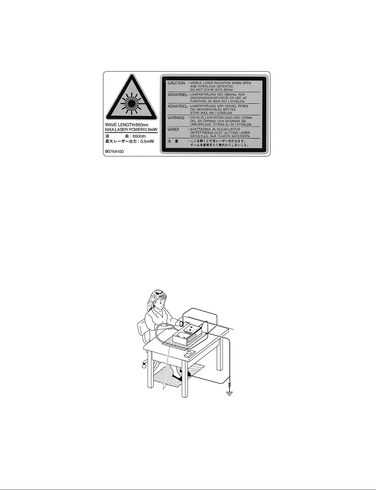
LASER BEAM CAUTION LABEL
S
When the power supply is being turned on, you may not remove this laser cautions label. If it removes, radiation of a laser
may be recceived.
PREPARATION OF SERVICING
Pickup Head consists of a laser diode that is very susceptible to external static electricity.
Although it operates properly after replacement, if it was subject to electrostatic discharge during replacement,
its life might be shortened. When replacing, use a conductive mat, soldering iron with ground wire, etc. to
protect the laser diode from damage by static electricity.
And also, the LSI and IC are same as above.
Ground conductive
wrist strap for body.
oldering iron
with ground wire
or ceramic type
1MΩ
Conductive mat
The ground resistance
between the ground line
and the ground is less than 10Ω.
SAFETY NOTICE
SAFETY PRECAUTIONS
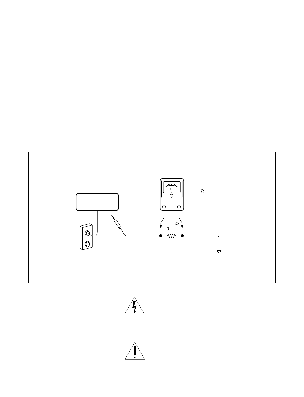
LEAKAGE CURRENT CHECK
Plug the AC line cord directly into a 120V AC outlet (do
not use an isolation transformer for this check). Use an
AC voltmeter, having 5000 Ω per volt or more sensitivity.
Connect a 1500 Ω 10 W resistor, paralleled by a 0.15 µF
150V AC capacitor between a known good earth ground
(water pipe, conduit, etc.) and all exposed metal parts of
cabinet (antennas, handle bracket, metal cabinet
screwheads, metal overlays, control shafts, etc.).
READING SHOULD NOT EXCEED 0.3V
Measure the AC voltage across the 1500 Ω resistor.
The test must be conducted with the AC switch on and
then repeated with the AC switch off. The AC voltage
indicated by the meter may not exceed 0.3 V. A reading
exceeding 0.3 V indicates that a dangerous potential
exists, the fault must be located and corrected.
Repeat the above test with the DVD VIDEO PLAYER
power plug reversed.
NEVER RETURN A DVD VIDEO PLAYER TO THE
CUSTOMER WITHOUT TAKING NECESSAR Y
CORRECTIVE ACTION.
DVD VIDEO PLAYER
AC OUTLET
Test all exposed metal.
Voltmeter Hook-up for Leakage Current Check
AC VOLTMETER
(5000 W per volt
or more sensitivity)
Good earth ground
such as a water pipe,
W
conduit, etc.
1500
10 W
0.15 µF 150V AC
The lightning flash with arrowhead symbol, within an
equilateral triangle, is intended to alert the user to the
presence of uninsulated “dangerous voltage” within the
product’s enclosure that may be of suf ficient magnitude to
constitute a risk of electric shock to persons.
The exclamation point within an equilateral triangle is
intended to alert the user to the presence of important
operating and maintenance (servicing) instructions in the
literature accompanying the appliance.

1. OPERATING INSTRUCTIONS
Specifications
2. LOCATION OF MAIN PARTS AND
MECHANISM PARTS
2-1. Location of Main Parts
2-2. Location of Mechanism Parts
CONTENTS
SECTION 1
GENERAL DESCRIPTIONS
3. TROUBLESHOOTING
3-1. Main Circuit
3-1-1. Servo System
3-1-2. Location Diagram of Servo Test Point
PART REPLACEMENT AND ADJUSTMENT PROCEDURES
1. REPLACEMENT OF MECHANICAL PARTS
1-1. Cabinet Replacement
1-1-1. Top Cover
1-1-2. Tray Panel
1-1-3. Front Panel
1-1-4. Rear Panel
1-2. PC Board Replacement
1-2-1. Main PC Board
1-2-2. Output PC Board
1-2-3. Power Supply PC board
1-2-4. Front Display and Power SW PC Boards
1. STANDING PC BOARDS FOR SERVICING
2. CIRCUIT SYMBOLS AND
SUPPLEMENTARY EXPLANATION
2-1. Precautions for Part Replacement
2-2. Solid Resistor Indication
2-3. Capacitance Indication
2-4. Inductor Indication
2-5. Waveform and Voltage Measurement
3. PRINTED WIRING BOARD AND
SCHEMATIC DIAGRAM
4. BLOCK DIAGRAMS
4-1. Overall Block Diagram
4-2. Power Supply Block Diagram
4-3. Front Display, Power Switch Block Diagram
SECTION 2
1-3. Mechanism Parts Replacement
1-3-1. Mechanism Chassis Assembly
1-3-2. Loading Belt
1-3-3. Loading Motor
1-3-4. Pickup Mechanism Assembly
1-3-5. Gear B Assembly, Gear A and
Rack Gear Assembly
1-3-6. Feed Motor
1-4. Tray Replacement
1-4-1. Tray Removal
1-4-2. Tray Mounting
SECTION 3
SERVICING DIAGRAMS
4-4. Main Block Diagrams
4-5. Output Block Diagram
5. CIRCUIT DIAGRAMS
5-1. Power Supply Circuit Diagram
5-2. Front Display, Power Switch Circuit Diagram
5-3. Main Circuit Diagram
5-4. Output Circuit Diagram
5-5. Motor System Circuit Diagrams
6. PC BOARDS
6-1. Power Supply PC Board
6-2. Power Switch PC Board
6-3. Disc LED PC Board
6-4. Main PC Board
6-5. Output PC Board
6-6. Front Display PC Board
SAFETY PRECAUTION
NOTICE
ABBREVIATIONS
1. Integrated Circuit (IC)
2. Capacitor (Cap)
3. Resistor (Res)
SECTION 4
PARTS LIST
4 . EXPLODED VIEWS
4-1. Packing Assembly
4-2. Chassis Assembly
4-3. Mechanism Assembly
5. PARTS LIST

GENERAL DESCRIPTIONS
SECTION 1
GENERAL DESCRIPTIONS
1. OPERATING INSTRUCTIONS
SECTION 1

Introduction
SAFETY PRECAUTIONS
WARNING
RISK OF ELECTRIC SHOCK
DO NOT OPEN
AVIS
WARNING : TO REDUCE THE RISK OF
ELECTRIC SHOCK, DO NOT REMOVE
COVER (OR BACK). NO USERSERVICEABLE
PARTS INSIDE. REFER SERVICING TO
QUALIFIED SERVICE PERSONNEL.
WARNING: TO REDUCE THE RISK OF FIRE OR ELECTRIC SHOCK, DO NOT EXPOSE THIS APPLIANCE
CAUTION: TO PREVENT ELECTRIC SHOCK, MATCH WIDE BLADE OF PLUG TO WIDE SLOT, FULLY
ATTENTION: POUR EVITER LES CHOCS ELECTRIQUES, INTRODUIRE LA LAME LA PLUS LARGE DE LA
CAUTION: This Digital Video Disc Player employs a Laser System.
RISQUE DE CHOC ELECTRIQUE NE
PAS OUVRIR
TO RAIN OR MOISTURE. DANGEROUS HIGH VOLTAGES ARE PRESENT INSIDE THE
ENCLOSURE. DO NOT OPEN THE CABINET . REFER SERVICING TO QUALIFIED PERSONNEL
ONL Y .
INSERT.
FICHE DANS LA BORNE CORRESPONDANTE DE LA PRISE ET POUSSER JUSQU’AU FOND.
To ensure proper use of this product, please read this owner’s manual carefully and retain for
future reference. Should the unit require maintenance, contact an authorized service location see service procedure.
The lightning flash with arrowhead symbol, within an equilateral triangle, is intended to alert the user to the presence of
uninsulated “dangerous voltage” within the product’s enclosure that may be of sufficient magnitude to constitute a risk
of electric shock to persons.
The exclamation point within an equilateral triangle is intended to alert the user to the presence of important operating and maintenance (servicing) instructions in the literature
accompanying the appliance.
Use of controls or adjustments or performance of procedures other than those specified herein
may result in hazardous radiation exposure.
To prev ent direct exposure to laser beam, do not try to open the enclosure.
Visible laser radiation when open and interlocks defeated.
DO NOT STARE INTO BEAM.
FCC NOTICE: This equipment has been tested and found to comply with the limits for a Class B digital device,
pursuant to part 15 of the FCC Rule. These limits are designed to provide reasonable protection
against harmful interference in a residential installation.
This equipment generates, uses, and can radiate radio frequency energy and, if not installed
and used in accordance with the instructions, may cause harmful interference to radio
communications.
However, there is no guarantee that interference will not occur in a particular installation.
If this equipment does cause harmful interference to radio or television reception, which can be
determined by turning the equipment off and on, the user is encouraged to try to correct the
interference by one or more of the following measures:
- Reorient or relocate the receiving antenna.
- Increase the separation between the equipment and receiver.
- Connect the equipment into an outlet on a circuit different from that to which the receiver is
connected.
- Consult the dealer or an experienced radio/TV technician for help.
WARNING: Changes or modifications made to this equipment, not expressly approved by Toshiba, or parties
authorized by Toshiba, could void the user’s authority to operate the equipment.
2
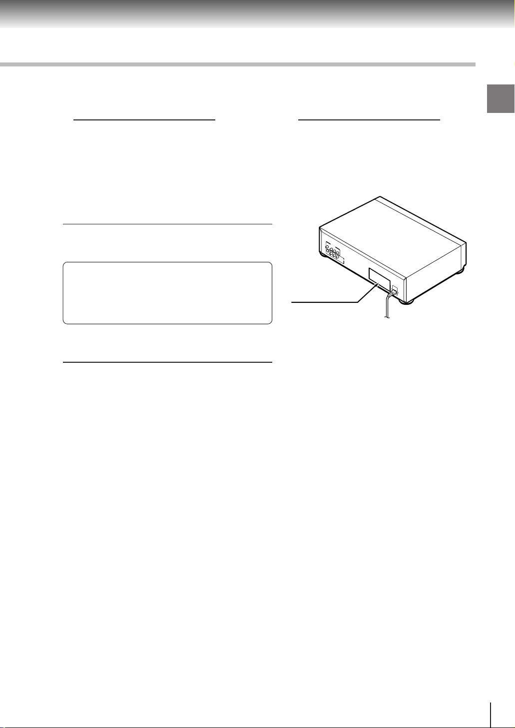
In the spaces provided below, record the Model and Serial No. located on the rear panel of your DVD video
player.
Model No. Serial No.
Retain this information for future reference.
Location of the required label
PRODUCT IS CERTIFIED BY THE MANUFACTURER TO
COMPLY WITH DHHS RULE 21CFR SUBCHAPTER J
APPLICABLE AT THE DATE OF MANUFACTURE.
MANUFACTURED
SERIAL NO
TOSHIBA CORPORATION
1-1,SHIBAURA 1-CHOME,MINATO-KU,
TOKYO 105-8001,JAPAN
Introduction
3
Introduction
IMPORTANT SAFETY INSTRUCTIONS
CAUTION: PLEASE READ AND OBSERVE ALL WARNINGS AND INSTRUCTIONS GIVEN IN THIS
OWNER’S MANUAL AND THOSE MARKED ON THE UNIT. RETAIN THIS BOOKLET FOR
FUTURE REFERENCE.
This set has been designed and manufactured to assure personal safety. Improper use can result in electric
shock or fire hazard. The safeguards incorporated in this unit will protect you if you observe the following
procedures for installation, use and servicing. This unit is fully transistorized and does not contain any parts that
can be repaired by the user.
DO NOT REMOVE THE CABINET COVER, OR YOU MAY BE EXPOSED TO DANGEROUS VOLTAGE.
REFER SERVICING TO QUALIFIED SERVICE PERSONNEL ONLY.
1. Read owner’s manual
After unpacking this product, read the owner’s manual carefully, and follow
all the operating and other instructions.
2. Power Sources
This product should be operated only from the type of power source indicated
on the label. If you are not sure of the type of power supply to your home,
consult your product dealer or local power company. For products intended
to operate from battery power, or other sources, refer to the operating
instructions.
3. Grounding or Polarization
This product may be equipped with a polarized alternating current line plug
(a plug having one blade wider than the other). This plug will fit into the
power outlet only one wa y. This is a safety feature. If you are unable to insert
the plug fully into the outlet, try reversing the plug. If the plug should still fail
to fit, contact your electrician to replace your obsolete outlet. Do not defeat
the safety purpose of the polarized plug.
4. Ventilation
Slots and openings in the cabinet are provided for ventilation and to ensure
reliable operation of the product and to protect it from overheating, and these
openings must not be blocked or covered. The openings should never be
blocked by placing the product on a bed, sofa, rug or other similar surface.
This product should not be placed in a built-in installation such as a bookcase
or rack unless proper ventilation is provided or the man ufacturer’ s instructions
have been adhered to.
5. Heat
The product should be situated away from heat sources such as radiators,
heat registers, stoves, or other products (including amplifiers) that produce
heat.
4

6. Water and Moisture
Do not use this product near water - for e xample, near a bath tub , w ash bowl,
kitchen sink, or laundry tub; in a wet basement; or near a s wimming pool and
the like.
7. Cleaning
Unplug this product from the wall outlet before cleaning. Do not use liquid
cleaners or aerosol cleaners. Use a damp cloth for cleaning.
8. Power-Cord Protection
Power-supply cords should be routed so that they are not likely to be walked
on or pinched by items placed upon or against them, paying particular attention
to cords at plugs, convenience receptacles, and the point where they exit
from the product.
9. Overloading
Do not overload wall outlets; extension cords, or integral convenience
receptacles as this can result in a risk of fire or electric shock.
Introduction
10.Lightning
For added protection for this product during storm, or when it is left unattended
and unused for long periods of time, unplug it from the wall outlet. This will
prevent damage to the product due to lightning and power-line surges.
11.Object and Liquid Entry
Never insert objects of any kind into this product through openings as they
may touch dangerous voltage points or short-out parts that could result in a
fire or electric shock. Never spill liquid of any kind on the product.
12.Attachments
Do not use attachments not recommended by the product manufacturer as they may cause hazards.
5
Introduction
IMPORTANT SAFETY INSTRUCTIONS
13.Accessories
Do not place this product on an unstable cart, stand, tripod, bracket, or table.
The product may fall, causing serious injury to a child or adult, and serious
damage to the product. Use only with a cart, stand, tripod, bracket, or table
recommended by the manufacturer, or sold with the product. Any mounting
of the product should follow the manufacturer’s instructions, and should use
a mounting accessory recommended by the manufacturer.
A product and cart combination should be moved with care. Quick stops,
excessive force, and uneven surfaces may cause the product and cart
combination to overturn.
14.Disc T ray
Keep your fingers well clear of the disc tray as it is closing. Neglecting to do
so may cause serious personal injury.
15.Burden
Do not place a heavy object on or step on the product. The object may fall,
causing serious personal injury and serious damage to the product.
S3125A
16.Headphones
When you use headphones, keep the volume at a moderate level. If you use
the headphones continuously with high volume sound, it may cause hearing
damage.
17.Disc
Do not use a cracked, deformed, or repaired disc. These discs are easily
broken and may cause serious personal injury and product malfunction.
18.Damage Requiring Service
Unplug this product from the wall outlet and refer servicing to qualified service personnel under the following
conditions:
a) When the power-supply cord or plug is damaged.
b) If liquid has been spilled, or objects have fallen into the product.
c) If the product has been exposed to rain or water.
d) If the product does not operate normally by following the operating instructions. Adjust only those
controls that are covered by the operating instructions as an improper adjustment of other controls ma y
result in damage and will often require extensive work by a qualified technician to restore the product to
its normal operation.
e) If the product has been dropped or damaged in any way.
f) When the product exhibits a distinct change in performance - this indicates a need for service.
6
19.Servicing
Do not attempt to service this product yourself as opening or removing covers
may expose y ou to dangerous voltage or other hazards . Refer all servicing to
qualified service personnel.
20.Replacement Parts
When replacement parts are required, be sure the service technician has used replacement parts specified
by the manufacturer or ha v e the same characteristics as the original part. Unauthorized substitutions ma y
result in fire, electric shock, or other hazards.
21.Safety Check
Upon completion of any service or repairs to this product, ask the service
technician to perform safety checks to determine that the product is in proper
operating condition.
Introduction
7
Introduction
Precautions
Notes on handling
When shipping the DVD video player, the original
shipping carton and packing materials come in handy.
For maximum protection, repack the unit as it was
originally packed at the factory.
Do not use volatile liquids, such as insect spray, near
the DVD video player. Do not leave rubber or plastic
products in contact with the DVD video player for a
long time. They will leave marks on the finish.
The top and rear panels of the DVD video player may
become warm after a long period of use. This is not a
malfunction.
When the DVD video player is not in use, be sure to
remove the disc and turn off the power.
If you do not use the DVD video player for a long
period, the unit may not function properly in the
future. Turn on and use the DVD video player
occasionally.
Notes on locating
Place the DVD video player on a level surface. Do not
use it on a shaky or unstable surface such as a
wobbling table or inclined stand. The loaded disc may
come off the proper position and cause damage to
the DVD video player.
When you place this DVD video player near a TV,
radio, or VCR, the playback picture may become poor
and the sound may be distorted. In this case, place
the DVD video player away from the TV, radio, or
VCR.
Notes on moisture condensation
Moisture condensation damages the DVD video
player. Please read the following carefully.
Moisture condensation occurs, for example, when you
pour a cold drink into a glass on a warm day. Drops of
water form on the outside of the glass. In the same way,
moisture may condense on the optical pick-up lens
inside this unit, one of the most crucial internal parts of
the DVD video player.
f
o
m
e
o
l
p
i
s
m
a
x
E
n
o
c
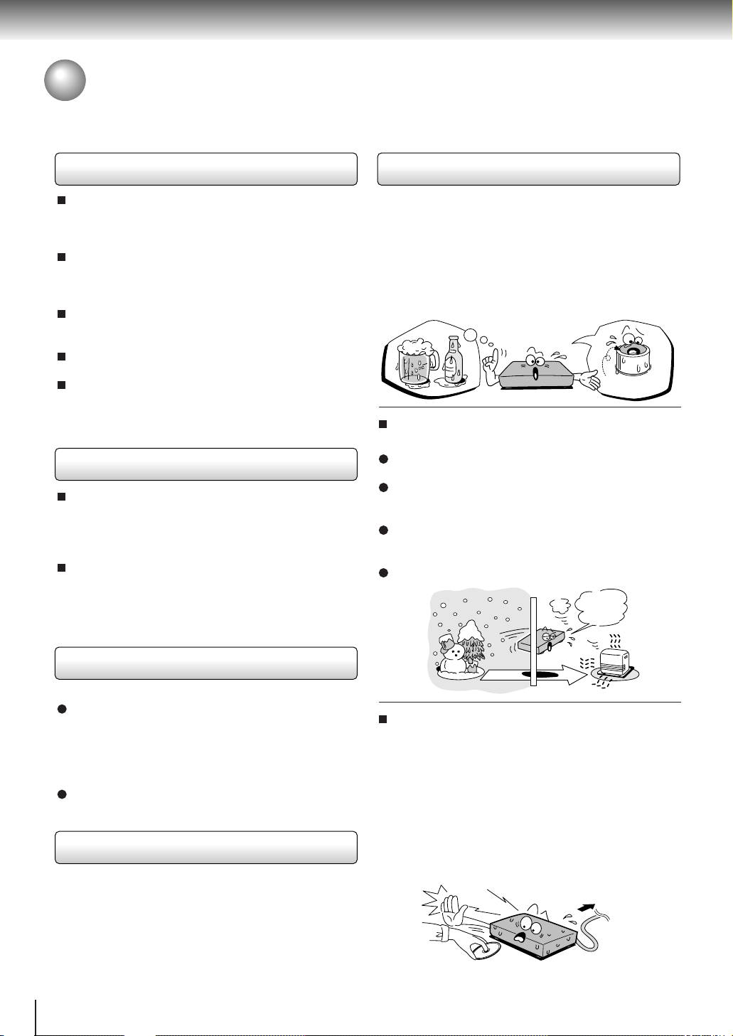
Moisture condensation occurs during the
following cases.
When you bring the DVD video player directly from a
cold place to a warm place.
When you use the DVD video player in a room where
you just turned on the heater, or a place where the
cold wind from the air conditioner directly hits the unit.
In summer, when you use the DVD video player in a
hot and humid place just after you move the unit from
an air conditioned room.
When you use the DVD video player in a humid place.
t
u
r
e
s
n
a
e
t
i
d
o
n
!
Optical pick-up
lens
It’s too
warm!
Notes on cleaning
Use a soft, dry cloth for cleaning.
For stubborn dirt, soak the cloth in a weak detergent
solution, wring well and wipe. Use a dry cloth to wipe
it dry.
Do not use any type of solvent, such as thinner and
benzine, as they may damage the surface of the DVD
video player.
If you use a chemical saturated cloth to clean the unit,
follow that product’s instructions.
To obtain a clear picture
The DVD video player is a high technology, precision
device. If the optical pick-up lens and disc drive parts
are dirty or worn down, the picture quality becomes
poor. To obtain a clear picture, we recommend regular
inspection and maintenance (cleaning or parts
replacement) every 1,000 hours of use depending on
the operating environment. For details, contact your
nearest dealer.
8
Do not use the DVD video player when moisture
condensation may occur.
If you use the DVD video player in such a situation, it
may damage discs and internal parts. Remove the
disc, connect the power cord of the DVD video player
to the wall outlet, turn on the DVD video player, and
leave it for two or three hours. After two or three
hours, the DVD video player will have warmed up and
evaporated any moisture. Keep the DVD video player
connected to the wall outlet and moisture
condensation will seldom occur.
Wait!
Wall outlet
Notes on Discs
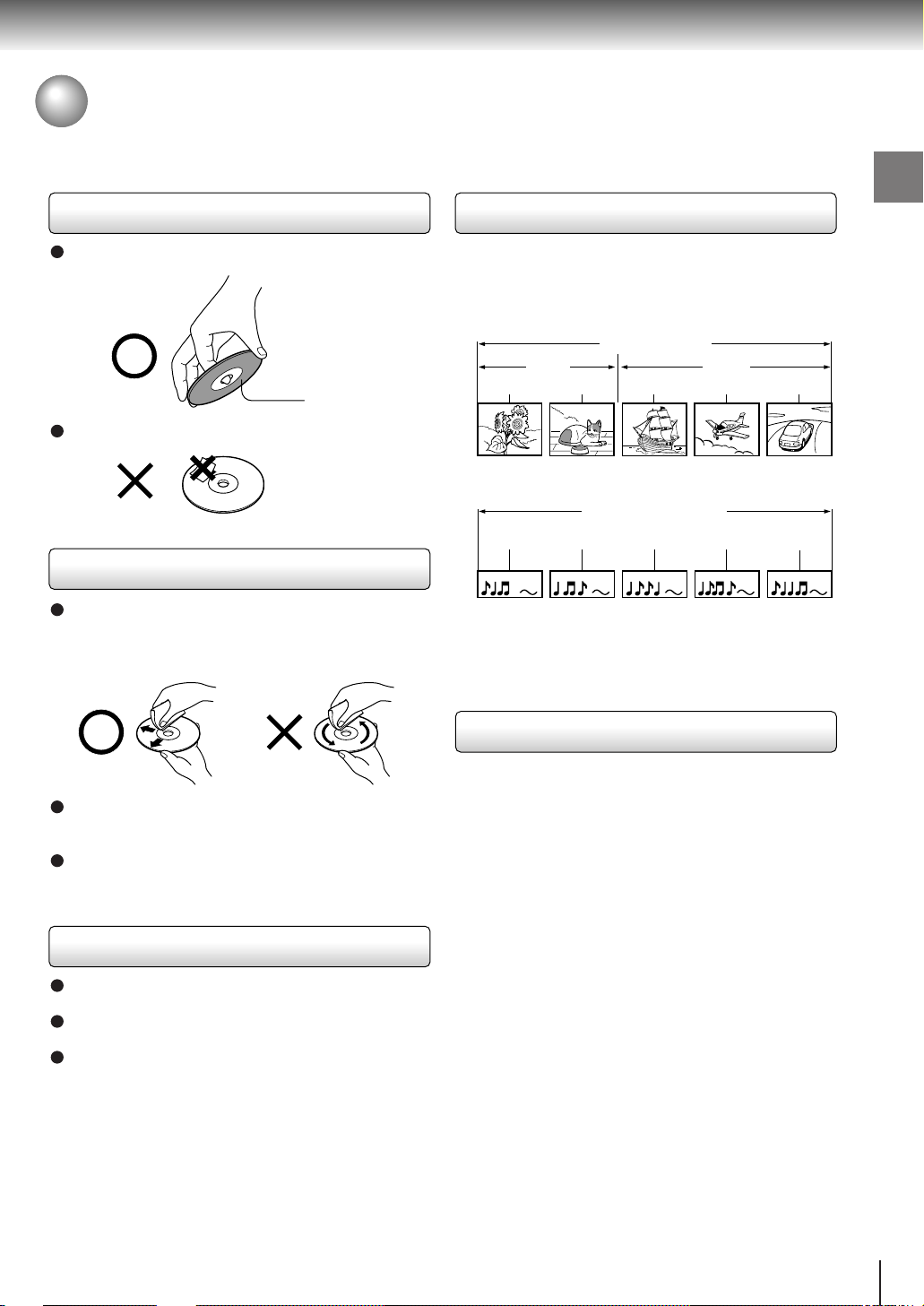
On handling discs
Do not touch the playback side of the disc.
Playback side
Do not attach paper or tape to discs.
On cleaning discs
Fingerprints and dust on the disc cause picture and
sound deterioration. Wipe the disc from the center
outwards with a soft cloth. Always keep the disc
clean.
Structure of disc contents
Normally, DVD video discs are divided into titles, and the
titles are sub-divided into chapters. VIDEO CDs/audio
CDs are divided into tracks.
DVD video disc
DVD video disc
Title 1 Title 2
Chapter 1 Chapter 2 Chapter 1 Chapter 2 Chapter 3
VIDEO CD/Audio CD
VIDEO CD/Audio CD
Track 1 Track 2 Track 3 Track 4 Track 5
Each title, chapter or track is assigned a number, which
is called “title number”, “chapter number” or “track
number” respectively.
There may be discs that do not hav e these n umbers.
Introduction
If you cannot wipe off the dust with a soft cloth, wipe
the disc lightly with a slightly moistened soft cloth and
finish with a dry cloth.
Do not use any type of solvent such as thinner,
benzine, commercially available cleaners or antistatic
spray for vinyl LPs. It may damage the disc.
On storing discs
Do not store discs in a place subject to direct sunlight
or near heat sources.
Do not store discs in places subject to moisture and
dust such as a bathroom or near a humidifier.
Store discs vertically in a case. Stacking or placing
objects on discs outside of their case may cause
warping.
Notes on copyright
It is forbidden by law to copy, broadcast, show,
broadcast on cable, play in public, and rent copyrighted
material without permission.
DVD video discs are copy protected, and any recordings
made from these discs will be distorted.
This product incorporates copyright protection
technology that is protected by method claims of certain
U.S. patents and other intellectual property rights owned
by Macrovision Corporation and other rights owners.
Use of this copyright protection technology must be
authorized by Macrovision Corporation, and is intended
for home and other limited viewing uses only unless
otherwise authorized by Macrovision Corporation.
Reverse engineering or disassembly is prohibited.
9
Introduction
Notes on Discs (continued)
About this owner’s manual
This owner’s manual explains the basic instructions of
this DVD video player. Some DVD video discs are
produced in a manner that allows specific or limited
operation during playback. As such, the DVD video
player may not respond to all operating commands. This
is not a defect in the DVD video player. Refer to
instruction notes of discs.
” may appear on the TV screen during operation.
“
” means that the operation is not permitted by the
A “
DVD video player or the disc.
Notes on region numbers
The region number of this DVD video player is 1. If
region numbers, which stand for their playable area, are
printed on your DVD video disc and you do not find
ALL
or
, disc playback will not be allowed by the player.
1
(In this case, the DVD video player will display a
message on-screen.)
On VIDEO CDs
This DVD video player supports VIDEO CDs equipped
with the PBC (Version 2.0) function. (PBC is the
abbreviation of Playback Control.) You can enjoy two
playback variations depending on types of discs.
• VIDEO CD not equipped with PBC function
(Version 1.1)
Sound and movie can be played on this DVD video
player in the same way as an audio CD.
• VIDEO CD equipped with PBC function
(Version 2.0)
In addition to operation of a VIDEO CD not equipped
with the PBC function, you can enjoy playback of
interactive software with search function by using the
menu displayed on the TV screen (Menu Playback).
Some of the functions described in this owner’s
manual may not work with some discs.
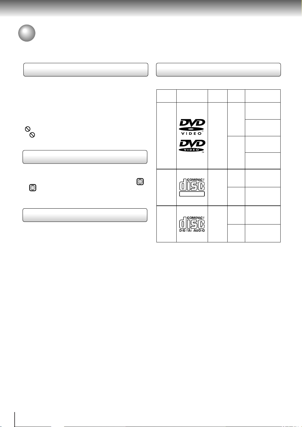
Playable discs
This DVD video player can play the following discs.
Disc
Size
12 cm
+
video
8 cm
12 cm
+
8 cm
12 cm
8 cm
(CD
single)
DVD
video
discs
VIDEO
CDs
Audio
CDs
Disc Mark
DIGITAL VIDEO
Contents
Audio
(moving
pictures)
Audio
video
(moving
pictures)
Audio
• You cannot play discs other than those listed above.
• You cannot play discs of CD-R, CD-RW, DVD-RAM,
DVD-RW, etc., even if they may be labeled marks
listed above.
• This DVD video player uses the NTSC color system,
and cannot play DVD video discs recorded in any
other color system (PAL, SECAM, etc.).
Maximum
playback time
Approx. 4 hours
(single sided disc)
Approx. 8 hours
(double sided disc)
Approx. 80 minutes
(single sided disc)
Approx. 160 minutes
(double sided disc)
Approx. 74 minutes
Approx. 20 minutes
Approx. 74 minutes
Approx. 20 minutes
10

Table of Contents
Introduction
SAFETY PRECAUTIONS ..........................2
IMPORT ANT SAFETY INSTRUCTIONS ...4
Precautions ...............................................8
Notes on Discs..........................................9
Notes on region numbers ...............................10
Table of Contents....................................11
Identification of Controls .......................12
Front panel ..................................................... 12
Rear panel...................................................... 12
DVD display.................................................... 13
Remote control ...............................................14
Loading batteries............................................ 15
Operating with the remote control .................. 15
Connections
Connecting to a TV.................................16
Connecting to a TV......................................... 16
Connecting to an audio system and TV
equipped with ColorStream
(Component video) inputs ............................17
®
Connecting to Optional Equipment ......18
Connecting to an amplifier equipped with a
Dolby Digital decoder ...................................18
Connecting to an amplifier equipped with
Dolby Pro Logic Surround ............................18
Connecting to an amplifier equipped with a
DTS decoder ................................................19
Connecting to an amplifier equipped with an
MPEG2 audio decoder................................. 19
Connecting to an amplifier equipped with a
digital audio input ......................................... 19
Basic playback
Playing a Disc .........................................20
Basic playback ...............................................20
Playing in fast reverse or fast forward
directions...................................................... 22
Playing frame by frame ..................................22
Playing in slow-motion.................................... 23
Resuming playback from the same location... 23
Locating a Specific Title, Chapter, or
Track ........................................................24
Locating a title using the top menu................. 24
Locating a title by entering the title number.... 24
Locating a specific chapter or track directly.... 25
Locating a specific chapter or track................ 25
Advanced playback
Accessing a Specific Location Directly ..
Entering the time of the desired location ........26
Playing Repeatedly.................................27
Repeating a title, chapter, or track.................. 27
Repeating a specific segment ........................ 27
Playing in a Favorite Order....................28
Setting titles, chapters, or tracks in a favorite
order............................................................. 28
Playing in Random Order ......................29
Playing titles, chapters or tracks in random
order............................................................. 29
Zooming a Picture ..................................30
Zooming a picture........................................... 30
Selecting 3-D (N-2-2) Sound
Enhancement ..........................................30
Selecting 3-D (N-2-2) sound enhancement.... 30
Selecting the Camera Angle ..................31
Changing the camera angle ........................... 31
Selecting Subtitles .................................32
Selecting a subtitle language .........................32
Selecting a Language.............................33
Selecting a playback audio setting .................33
Viewing the Operational Information
and DVD/CD-T ext ....................................34
Checking the operational status .....................34
Checking the remaining time and setting
status............................................................ 34
Function setup
Customizing the Function Settings ......35
Setting procedure ...........................................35
Setting details................................................. 37
Others
Table of Languages ................................42
Before Calling Service Personnel ......... 43
Specifications .........................................44
LIMITED WARRANTY DVD VIDEO
PLAYER ...................................................45
Introduction
26
11
Introduction
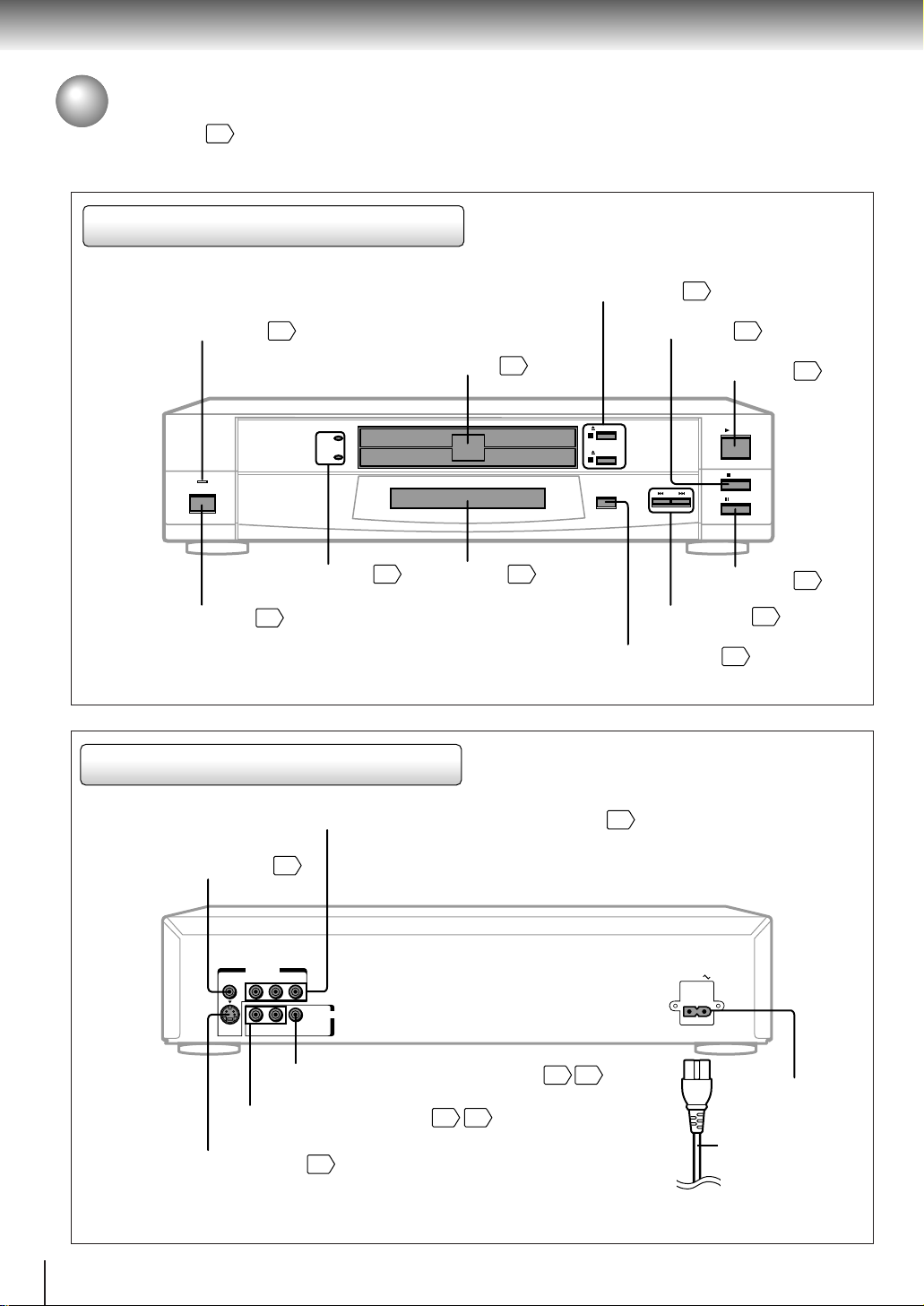
Identification of Controls
See the page in for details.
Front panel
POWER indicator
POWER
POWER button
Rear panel
20
DISC-1
DISC-2
DISC-1/2 indicators
20
DVD display
20
Disc tray
OPEN/CLOSE 1/2 buttons
STOP button
20
OPEN/CLOSE
1
OPEN/CLOSE
2
DISC SELECT
13
SKIP buttons
DISC SELECT button
20
21
PLAY button
PLAY
STOP
SKIP
PAUSE
PAUSE button
20
20
21
25
12
ColorStream® (Component video) VIDEO OUT jacks (Y/PB/PR)
VIDEO OUT jack
VIDEO Y P
ANALOG AUDIO OUT jacks
S VIDEO OUT jack
16
VIDEO OUT
B PR
AUDIO OUT
BITSTREAM/
L
R
S
ANALOG
PCM
BITSTREAM/PCM AUDIO OUT jack
16
18 19
16 17
17
AC IN
AC inlet
Power cord
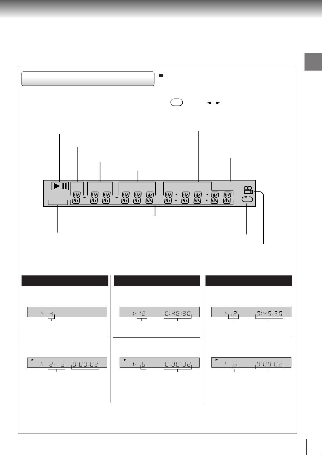
DVD display
Pressing of the FL DIMMER button on the remote
control turns the DVD display on or off.
FL DIMMER
On
Off
Introduction
Play mode indicator
Total playing time/remaining time/elapsed time indicators
Disc number indicator
Title/track number indicator
Chapter number indicator
DISC TITLE TRK CHP INDEX TOTAL REMAIN MEMORY
HDCD
SVCDVD
Multifunctional indicator (indicates operating
status or messages, etc.)
DVD/VIDEO CD/CD indicator
The indicators vary depending on the kinds of discs you play.
DVD video disc
• When closing the disc tray:
Example
DISC TITLE TRK CHP INDEX TOTAL REMAIN MEMORY
HDCD
SVCDVD
• When closing the disc tray:
Example
SVCDVD
VIDEO CD
DISC TITLE TRK CHP INDEX TOTAL REMAIN MEMORY
HDCD
Memory playback indicator
Repeat playback indicator
Angle icon indicator
Audio CD
• When closing the disc tray:
Example
DISC TITLE TRK CHP INDEX TOTAL REMAIN MEMORY
HDCD
SVCDVD
Total number of titles
• During playback:
Example
DISC TITLE TRK CHP INDEX TOTAL REMAIN MEMORY
HDCD
SVCDVD
Playing chapter 3
of title 2
Elapsed time
of the current
title
Some discs may not display chapter
numbers or elapsed time.
Total number of
tracks
Total playing
time of the disc
• During playback:
Example
DISC TITLE TRK CHP INDEX TOTAL REMAIN MEMORY
HDCD
SVCDVD
Playing track 6
Elapsed time of
the current
track
Some discs may not display track
numbers or elapsed time.
Total number of
tracks
• During playback:
Example
DISC TITLE TRK CHP INDEX TOTAL REMAIN MEMORY
HDCD
SVCDVD
Playing track 6
Total playing
time of the disc
Elapsed time of
the current
track
13
Introduction
Identification of Controls (continued)
The instructions in this manual describe the functions on the remote control. See the page in for details.
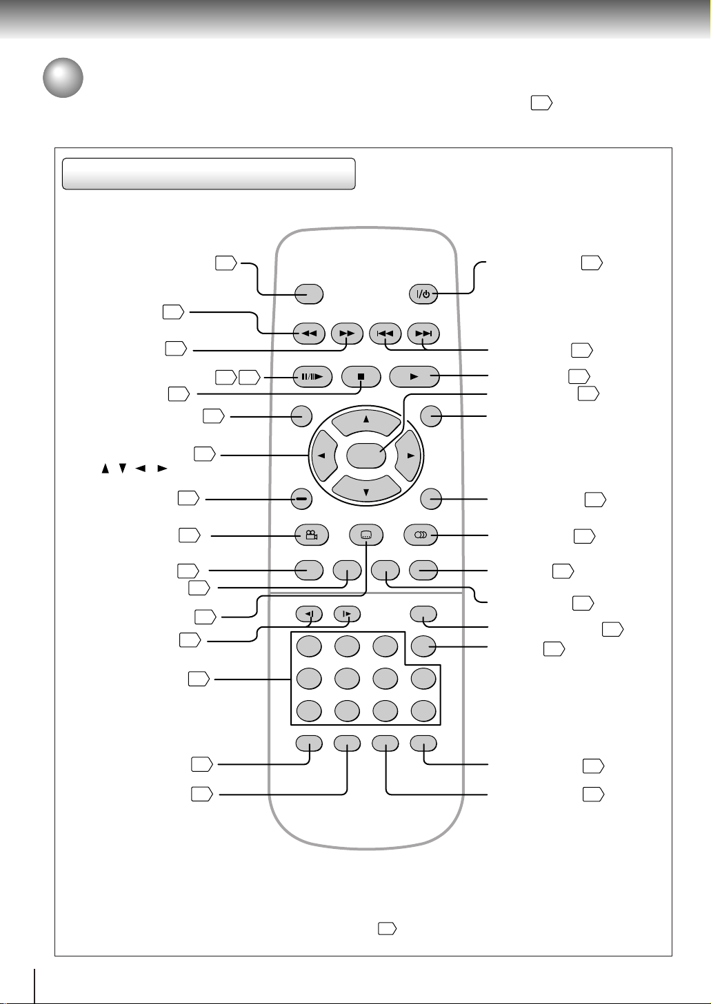
Remote control
DISC SELECT button
REV button
FWD button
22
22
PAUSE/STEP button
STOP button
21
TOP MENU button
Direction buttons
35
( / / / )
CLEAR button
ANGLE button
SETUP button
DISPLAY button
SUBTITLE button
SLOW buttons
25
31
35
34
32
23
24
20
21 22
DISC SELECT
FWD
PAUSE/STEP
TOP MENU
CLEAR
ANGLE SUBTITLE AUDIO
SETUP 3DZOOMDISPLAY
STOP PLAY
ENTER
SLOW FL DIMMER
21
SKIPREV
POWER
MENU
RETURN
SEARCH
T
POWER button
SKIP buttons
PLAY button
ENTER button
20
25
20
35
MENU button*
RETURN button
AUDIO button
3D button
ZOOM button
33
30
30
FL DIMMER button
T button
24
35
13
14
Number buttons
RANDOM button
MEMORY button
24
29
28
456
78390
MEMORY
RANDOM
REPEAT
+10
A-B RPT
* MENU button
Use the MENU button to display the menu included on
many DVD video discs. To operate a menu, follow the
instructions in “Locating a title using the top menu.”
24
A-B RPT button
REPEAT button
27
27
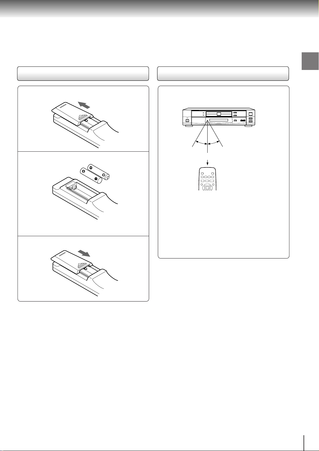
Loading batteries
30°
30°
DISC-2
DISC-1
1
2
Operating with the remote control
Introduction
Open the cover.
1
Insert batteries (AA size).
2
Make sure to match the + and – on the batteries
to the marks inside the battery compartment.
Close the cover.
3
Notes on batteries
Improper use of batteries may cause battery leakage and
corrosion. To operate the remote control correctly, follow the
instructions below.
• Do not insert batteries into the remote control in the wrong
direction.
• Do not charge, heat, open, or short-circuit the batteries.
Do not throw batteries into a fire.
• Do not leave dead or exhausted batteries in the remote
control.
• Do not use different types of batteries together, or mix old
and new batteries.
• If you do not use the remote control for a long period of
time, remove the batteries to avoid possible damage from
battery corrosion.
• If the remote control does not function correctly or if the
operating range becomes reduced, replace all batteries
with new ones.
• If battery leakage occurs, wipe the battery liquid from the
battery compartment, then insert new batteries.
Point the remote control at the remote
sensor and press the buttons.
Within about 7 m (23 feet)
Distance:About 7 m (23 feet) from the front of the
remote sensor
Angle: About 30° in each direction of the front of
the remote sensor
* Do not expose the remote sensor of the DVD video
player to a strong light source such as direct
sunlight or other illumination. If you do so, you may
not be able to operate the DVD video player via the
remote control.
Notes on the remote control
• Direct the remote control at the remote sensor of the DVD
video player.
• Do not drop or give the remote control a shock.
• Do not leave the remote control near an extremely hot or
humid place.
• Do not spill water or put anything wet on the remote
control.
• Do not open the remote control.
15
Connections
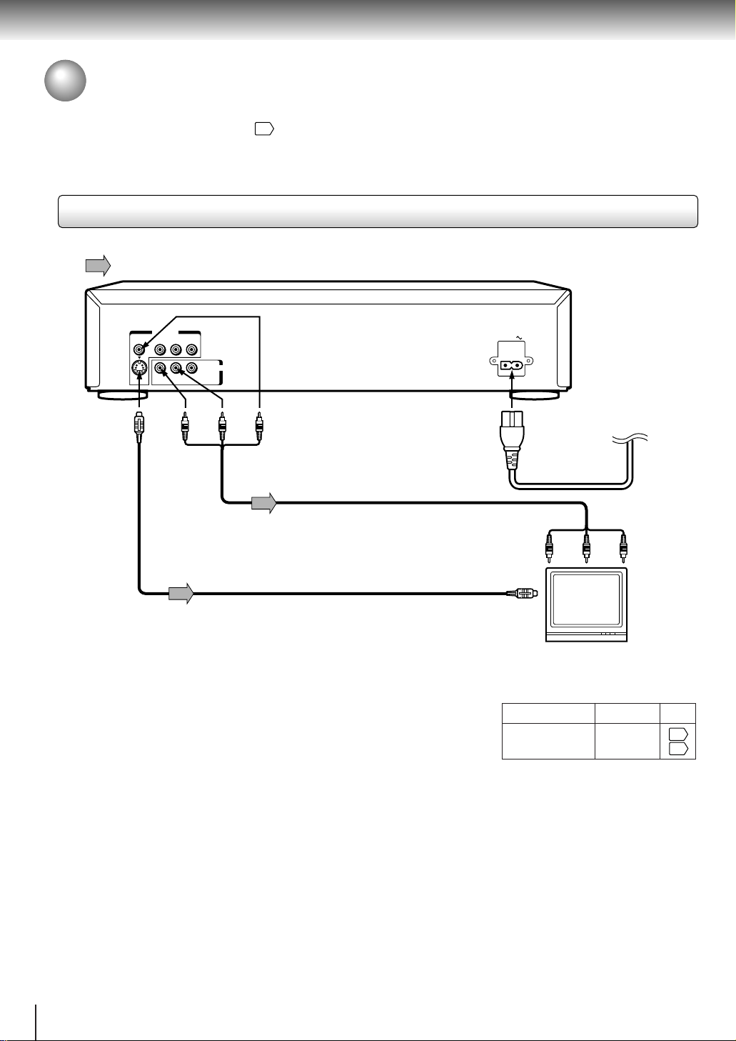
Connecting to a TV
Connect the DVD video player to your TV.
For details of output sound, see 33.
Connecting to a TV
Signal flow
To S VIDEO
OUT
VIDEO OUT
VIDEO Y P
R
S
ANALOG
To ANALOG
AUDIO OUT
B PR
L
BITSTREAM/
PCM
(red)
AUDIO OUT
(yellow)
(white)
T o VIDEO OUT
Audio/video cable
(supplied)
S video cable (not supplied)
If the TV has an S video input, connect the
DVD video player with an S video cable.
When using an S video cable, do not
connect the yellow video cable.
AC IN
To audio inputs
(red)
To S video input
TV or monitor with
audio/video inputs
• Make the following setting.
On-screen display
“Audio Out Select”
To wall outlet
To video
input
(yellow)
(white)
Select:
“Analog 2ch”
Page
35
39
Notes
• Refer to the owner’s manual of the connected TV as well.
• When you connect the DVD video player to your TV, be sure to turn off the power and unplug both units from the wall outlet
before making any connections.
• If your television set has one audio input, connect the DVD video player to a Y cable adapter (not supplied) and then connect
to your TV.
• Connect the DVD video player directly to your TV. If you connect the DVD video player to a VCR, TV/VCR combination or
video selector, the playback picture may be distorted as DVD video discs are copy protected.
16
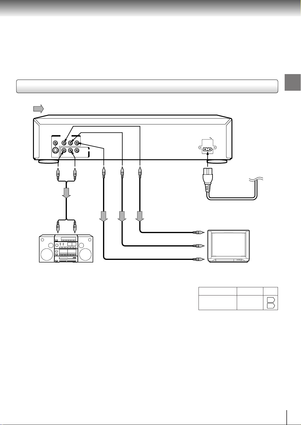
Connecting to an audio system and TV equipped with ColorStream
®
(Component video) inputs
Signal flow
Connections
VIDEO OUT
VIDEO Y P
(red)
To ANALOG
S
R
ANALOG
(white)
BPR
L
BITSTREAM/
PCM
AUDIO OUT
VIDEO
To PR
OUT
To PB
VIDEO
OUT
To Y
VIDEO
OUT
AUDIO OUT
To audio inputs of
the amplifier
(red) (white)
To Y video input
To PB video input
To PR video input
Audio system
ColorStream® (Component video) outputs/inputs
Some TVs or monitors are equipped with component video inputs. Connecting to
these inputs allows you to enjoy higher quality picture playback.
Actual labels for component video inputs may vary depending on the TV
manufacturer. (ex. Y, R-Y, B-Y or Y, C
B, CR)
In some TVs or monitors, the color levels of the playback picture may be reduced
slightly or the tint may change. In such a case, adjust the TV or monitor for
optimum performance.
AC IN
To wall outlet
TV or monitor with
component video inputs
• Make the following setting.
On-screen display
“Audio Out Select”
Select:
“Analog 2ch”
Page
35
39
Notes
• Refer to the owner’s manual of the connected equipment as well.
• When you connect the DVD video player to other equipment, be sure to turn off the power and unplug all of the equipment
from the wall outlet before making any connections.
• If you place the DVD video player near a tuner or radio, the radio broadcast sound might be distorted. In this case, place the
DVD video player away from the tuner and radio.
• The output sound of the DVD video player has a wide dynamic range. Be sure to adjust the receiver’s volume to a moderate
listening level. Otherwise, the speakers may be damaged by a sudden high volume sound.
• Turn off the amplifier before you connect or disconnect the DVD video player’s power cord. If you leave the amplifier power
on, the speakers may be damaged.
17
Connections
Connecting to Optional Equipment
You can enjoy high quality dynamic sounds by connecting the DVD video player
to optional audio equipment.
16
For connection to your TV, see “Connecting to a TV”
33
For details of output sound, see
.
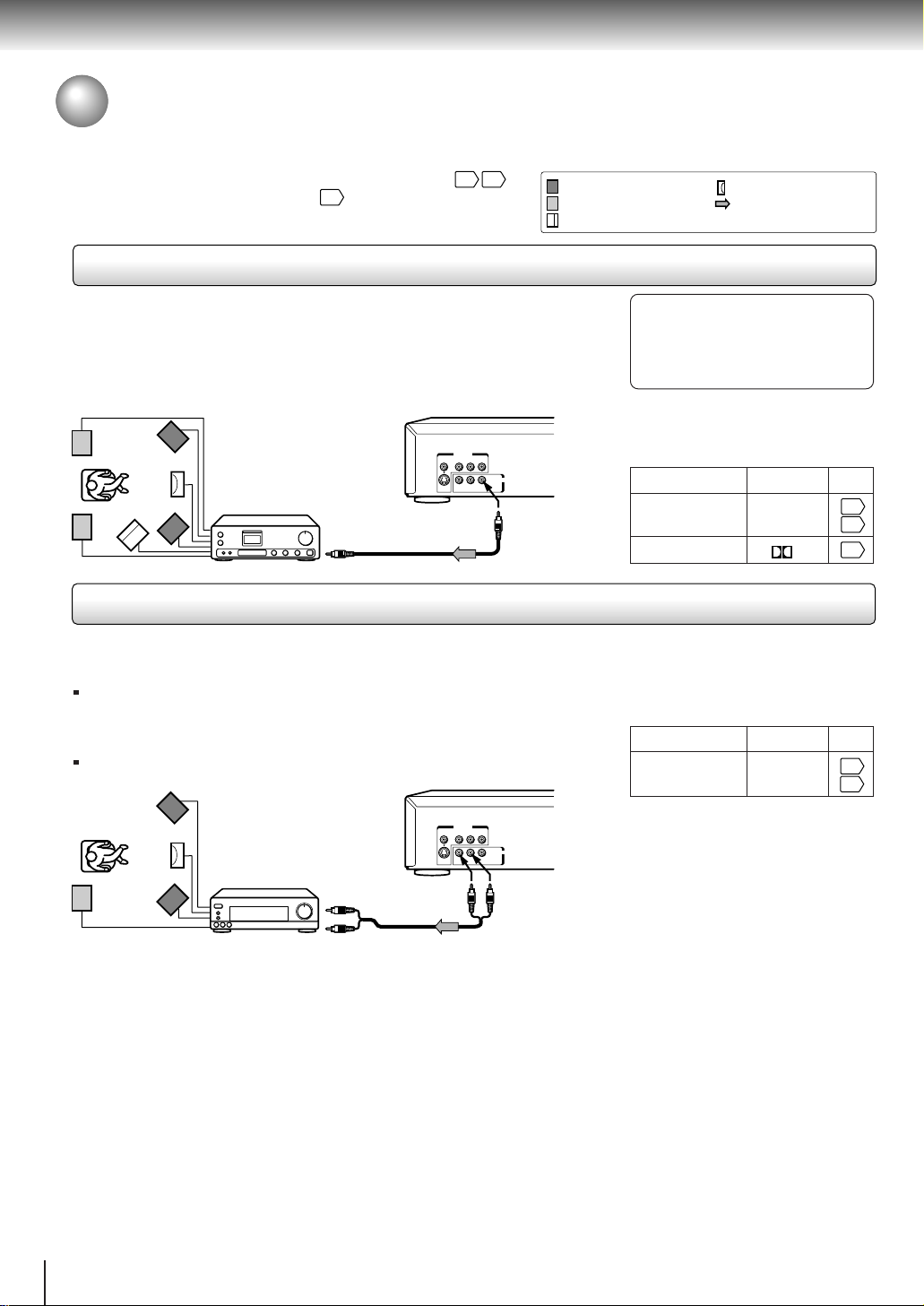
Connecting to an amplifier equipped with a Dolby Digital decoder
17
.
: Front speaker
: Rear speaker
: Center speaker
: Signal flow
: Sub woofer
Dolby Digital
Dolby Digital is the surround sound technology used in theaters showing the latest movies,
and is now available to reproduce this realistic effect in the home. You can enjoy motion
picture and live concert DVD video discs with this dynamic realistic sound by connecting the
DVD video player to a 6 channel amplifier equipped with a Dolby Digital decoder or Dolby
Digital processor. If you have a Dolby Pro Logic Surround decoder, you will obtain the full
benefit of Pro Logic from the same DVD movies that provide full 5.1-channel Dolby Digital
soundtracks, as well as from titles with the Dolby Surround mark.
Manufactured under license from Dolby
Laboratories. “Dolby” and the double-D
symbol are trademarks of Dolby
Laboratories. Confidential unpublished
works. ©1992-1997 Dolby Labor atories.
All rights reserved.
• Use DVD video discs encoded via
the Dolby Digital recording
system.
• Make the following setting.
On-screen display
“Audio Out Select”
Recording system
Select:
“Bitstream”
D
Page
Amplifier equipped
with a Dolby Digital
decoder
VIDEO Y P
75 Ω coaxial cable
To digital audio input
VIDEO OUT
B PR
AUDIO OUT
BITSTREAM/
L
R
S
PCM
ANALOG
To BITSTREAM/
PCM AUDIO OUT
Connecting to an amplifier equipped with Dolby Pro Logic Surround
Dolby Pro Logic Surround
You can enjoy the dynamic realistic sound of Dolby Pro Logic Surround by connecting an amplifier and speaker system (right and left
front speakers, a center speaker, and one or two rear speakers).
With an amplifier equipped with Dolby Digital
Connect the equipment the same way as described in “Connecting to an amplifier
equipped with a Dolby Digital decoder.” Refer to that amplifier’s owner’s manual and set
the amplifier so you can enjoy Dolby Pro Logic Surround sound.
With an amplifier not equipped with Dolby Digital
Connect the equipment as follows.
• Make the following setting.
On-screen display
“Audio Out Select”
Select:
“Analog 2ch”
Page
35
39
35
39
33
18
VIDEO OUT
B PR
VIDEO Y P
Amplifier equipped
with Dolby Pro Logic
*
Surround
To audio input
AUDIO OUT
BITSTREAM/
L
R
S
PCM
ANALOG
To ANALOG
AUDIO OUT
Audio cable
Be sure to set “Audio Out Select”
to “Analog 2ch” when you enjoy
sounds of Dolby Pro Logic
Surround using this connection.
* Connect one or two rear speakers.
The output sound from the rear speakers will be
monaural even if you connect two rear speakers.
Warning
• When you are connecting (via the BITSTREAM/PCM AUDIO OUT jack) an AV decoder that does not have Dolby Digital,
Digital Theater Systems (DTS) or MPEG2 decoding function, be sure to set “Audio Out Select” to “PCM” from the onscreen displays
. Otherwise, high volume sound may damage your hearing as well as the speakers.
35
39
• When playing DTS-encoded discs (DVD video discs and audio CDs), excessive noise may be output from the analog
stereo jacks. To avoid possible damage to the audio system, you should take proper precautions when the ANALOG
AUDIO OUT jacks of the DVD video player are connected to an amplification system. To enjoy DTS Digital Surround™
playback, an external 5.1 channel DTS Digital Surround™ decoder system must be connected to the BITSTREAM/PCM
AUDIO OUT jack of the DVD video player.
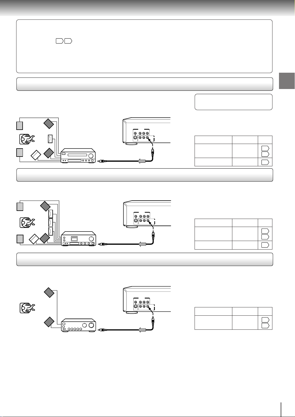
Connecting to an amplifier equipped with a DTS decoder
Digital Theater Systems (DTS)
DTS is a high quality surround technology used in theaters and now available for home use,
on DVD video discs or audio CDs.
If you have a DTS decoder or processor, you can obtain the full benefit of 5.1 channel DTS
encoded sound tracks on DVD video discs or audio CDs.
VIDEO OUT
B PR
VIDEO Y P
AUDIO OUT
BITSTREAM/
L
R
S
PCM
Amplifier equipped
ANALOG
with a DTS decoder
To BITSTREAM/
75 Ω coaxial cable
PCM AUDIO OUT
To digital audio input
“DTS” and “DTS Digital Surround” are
trademarks of Digital Theater Systems,
Inc.
• Use DVD video discs or audio
CDs encoded via the DTS
recording system.
• Make the following setting.
On-screen display
“Audio Out Select”
Recording system DTS
Select:
“Bitstream”
Connecting to an amplifier equipped with an MPEG2 audio decoder
MPEG2 sound
You can enjoy motion picture and live concert DVD video discs with dynamic realistic sound by
connecting an amplifier equipped with an MPEG2 audio decoder or MPEG2 audio processor.
• Use DVD video discs encoded via
the MPEG2 recording system.
• Make the following setting.
On-screen display
“Audio Out Select”
Recording system
Select:
“Bitstream”
MPEG
Amplifier equipped
with an MPEG2
audio decoder
VIDEO Y P
75 Ω coaxial cable
To digital audio input
VIDEO OUT
BPR
AUDIO OUT
BITSTREAM/
L
R
S
PCM
ANALOG
To BITSTREAM/
PCM AUDIO OUT
Connections
Page
35
39
33
Page
35
39
33
Connecting to an amplifier equipped with a digital audio input
2 channel digital stereo
You can enjoy the dynamic sound of 2 channel digital stereo by connecting an amplifier
equipped with a digital audio input and speaker system (right and left front speakers).
VIDEO OUT
B PR
VIDEO Y P
AUDIO OUT
BITSTREAM/
L
R
S
PCM
ANALOG
To BITSTREAM/
PCM AUDIO OUT
Notes
Amplifier equipped with
a digital audio input
75 Ω coaxial cable
To digital audio input
• DO NOT connect the BITSTREAM/PCM AUDIO OUT jack of the DVD video player to the AC-3 RF input of a Dolby Digital
Receiver. This input on your A/V Receiver is reserved for Laserdisc use only and is incompatible with the BITSTREAM/PCM
AUDIO OUT jack of the DVD video player.
• Connect the BITSTREAM/PCM AUDIO OUT jack of the DVD video player to the “COAXIAL” input of a Receiver or Processor.
• Refer to the owner’s manual of the connected equipment as well.
• When you connect the DVD video player to other equipment, be sure to turn off the power and unplug all of the equipment
from the wall outlet before making any connections.
• The output sound of the DVD video player has a wide dynamic range. Be sure to adjust the receiver’s volume to a moderate
listening level. Otherwise, the speakers may be damaged by a sudden high volume sound.
• Turn off the amplifier before you connect or disconnect the DVD video player’s power cord. If you leave the amplifier power
on, the speakers may be damaged.
• Make the following setting.
On-screen display Select:
“PCM”“Audio Out Select”
Page
35
39
19
Basic playback
38
24
TV Shape
Thank you for your purchase of this TOSHIBA DVD Player.
Please make a selection
for On-Screen Language and your TV Shape and
press ENTER button on your remote control.
TOSHIBA
FIRST SETUP
On-Screen Language
4:3LB
ENG
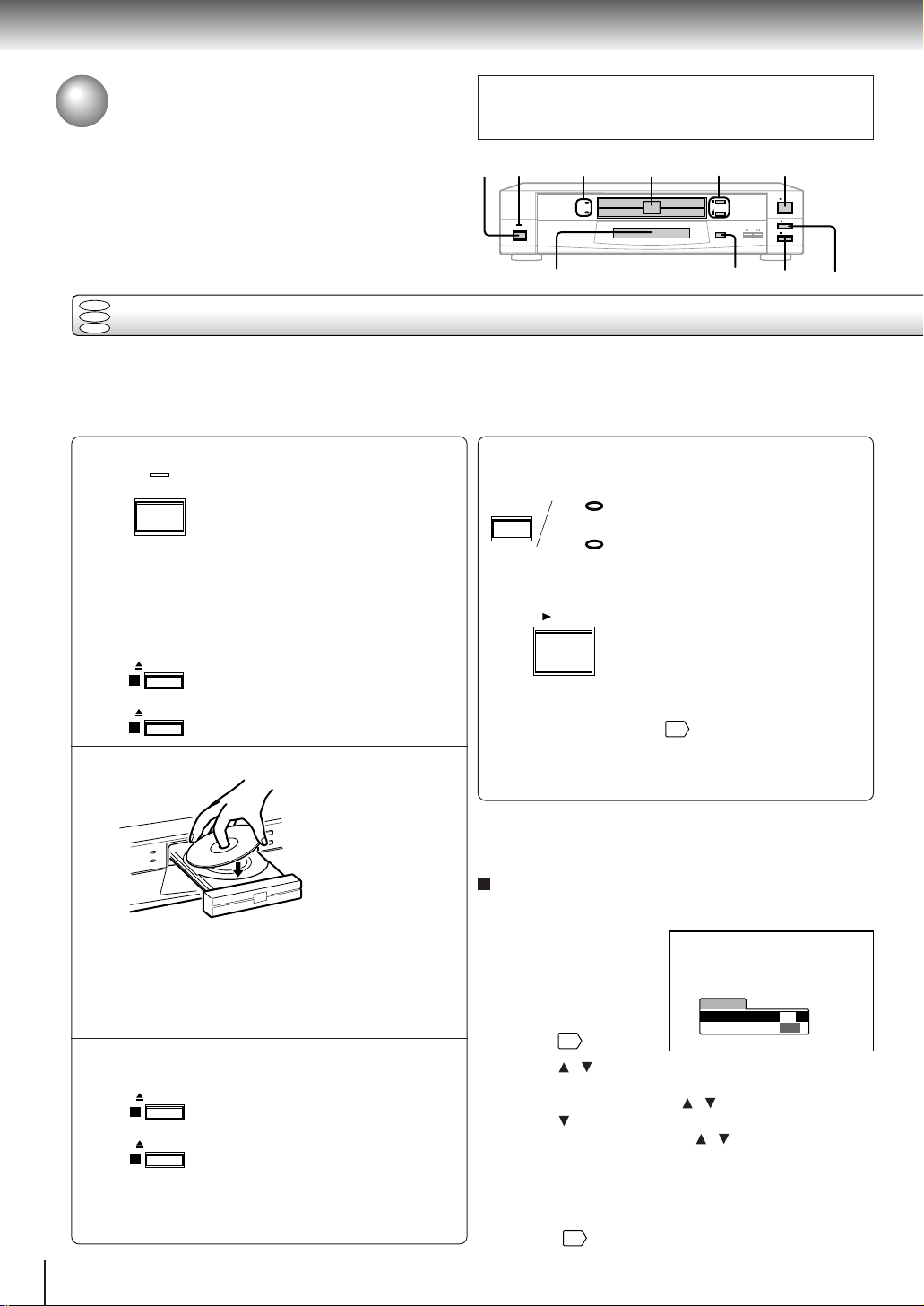
Playing a Disc
This section shows you the basics on how to play a disc.
CAUTION
Keep your fingers well clear of the disc tr ay as it is closing.
Neglecting to do so may cause serious personal injury.
POWER
1
indicator
DISC-1/2
indicators
DISC-1
POWER
DISC-2
2, 4
3
OPEN/CLOSE
1
OPEN/CLOSE
2
DISC SELECT
6
PLAY
STOP
SKIP
PAUSE
DVD
VCD
Basic playback
CD
Preparations
• When you want to view a disc, turn on the TV and select the video input connected to the DVD video player.
• When you want to enjoy the sound of discs from the audio system, turn on the audio system and select the input connected
to the DVD video player.
Press POWER.
1
POWER
When the DVD video player is turned on for
the first time, an initial set-up display appears.
See “Initial set-up” to make the settings before
proceeding to step 2.
Press OPEN/CLOSE (1/2).
2
OPEN/CLOSE
1
OPEN/CLOSE
2
Place a disc on the disc tray.
3
• There are two different disc sizes. Place the disc in
the correct guide on the disc tray. If the disc is out of
the guide, it may damage the disc and cause the
DVD video player to malfunction.
• Do not place anything except DVD video discs,
VIDEO CDs or audio CDs on the disc tray.
Press OPEN/CLOSE (1/2) to close the
disc tray.
4
20
OPEN/CLOSE
1
OPEN/CLOSE
2
• Some discs may be automatically played after
having been set. Even in the playback, you can
select a disc to play in step 5.
The DVD video player turns on and
the POWER indicator on the player
illuminates.
Press either button you want.
The disc tray opens.
With the playback
side down.
Do not place more
than one disc.
Press the button which you pressed
in step 2.
To set another disc, press the other
button.
DVD display
5
PAUSE
STOP
Press DISC SELECT repeatedly to
select the disc you want.
5
DISC SELECT
DISC-1
DISC-2
Red (lit): The disc is on standby or is
being played.
Green (lit): Secondary standby.
Off: Playback does not start.
Press PLAY.
6
Note
Even while playing a disc, you can set another disc. Press the
OPEN/CLOSE (1/2) button for a disc which is not played.
Initial set-up
Make the following settings on the display.
On-Screen Language:
Select the appropriate
on-screen language.
TV Shape: Select a
picture size according to
the aspect ratio of your
TV. (See
1 Press
2 Select a language using
3 Press
4 Select a picture size using
5 Finally press SETUP.
All your selections are entered and the display
disappears.
To change your settings, see “Customizing the Function
Settings.”
PLAY
Playback starts.
If you insert a DVD video disc that contains a top
menu, a menu may appear. See “Locating a title
using the top menu.”
• You may need to press the TOP MENU or MENU
button to display disc menu (depending on the actual
DVD video disc.)
for details.)
/ to select “On-Screen Language,” and
press ENTER.
/ , and press ENTER.
to select “TV Shape,” and press ENTER.
/ , and press ENTER.
35
40
5
1
PAUSE/STEP
6
STOP
MENU
ENTER
/
SETUP
TOP MENU
To obtain a higher quality picture
Occasionally, some picture noise not usually visible during a normal broadcast
may appear on the TV screen while playing a DVD video disc because the high
resolution pictures on these discs include a lot of information. While the amount of
noise depends on the TV you use with this DVD video player, you should generally
reduce the sharpness adjustment on your TV when viewing DVD video discs.
About
The
DVD VCD CD
DVD VCD CD
icons on the heading bar show the playable discs for the
function described under that heading.
DVD
: You can use this function with DVD video discs.
VCD
: You can use this function with VIDEO CDs.
CD
: You can use this function with audio CDs.
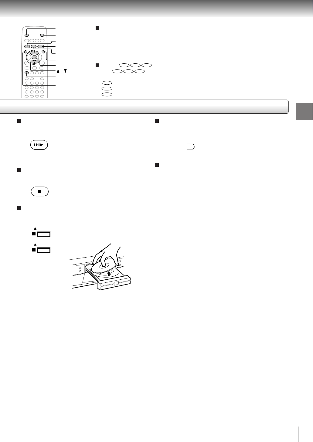
To pause playback (still mode)
Press PAUSE/STEP during playback.
PAUSE/STEP
To resume normal playback, press
the PLAY button.
• The sound is muted during still
mode.
To stop playback
Press STOP.
STOP
To remove the disc
Press OPEN/CLOSE (1/2) for the disc you want to
remove.
OPEN/CLOSE
1
OPEN/CLOSE
2
Remove the disc after the disc tray
opens completely.
About the screen saver
If you pause a picture of a DVD video disc and leave it
still for a long while, the screen saver of the DVD video
player automatically appears (when “Screen Saver” is
set to “On”
). To turn off the screen saver, press the
PLAY button.
Automatic Power Off function
If the DVD video player is stopped, or the screen saver
is engaged for approximately 20 minutes, the DVD
video player will automatically turn itself off.
Basic playback
Be sure to press the OPEN/CLOSE (1/2) button to
close the disc tray after you remove the disc.
Notes
• Do not move the DVD video player during playback. Doing so may damage the disc.
• Use the OPEN/CLOSE (1/2) button to open and close the disc tray. Do not push the disc tray while it is moving. Doing so may
cause the DVD video player to malfunction.
• Do not push up on the disc tray or put any objects other than discs on the disc tray. Doing so may cause the DVD video
player to malfunction.
• In many instances, a menu screen will appear after playback of a movie is completed. Prolonged display of an on-screen
menu may damage your television set, permanently etching that image onto its screen. To avoid this, be sure to press the
STOP button on your remote control once the movie is completed.
21
Basic playback
Playing a Disc (continued)
You can play discs at various speeds, and resume playback from the location
where you stopped playback.
DVD
VCD
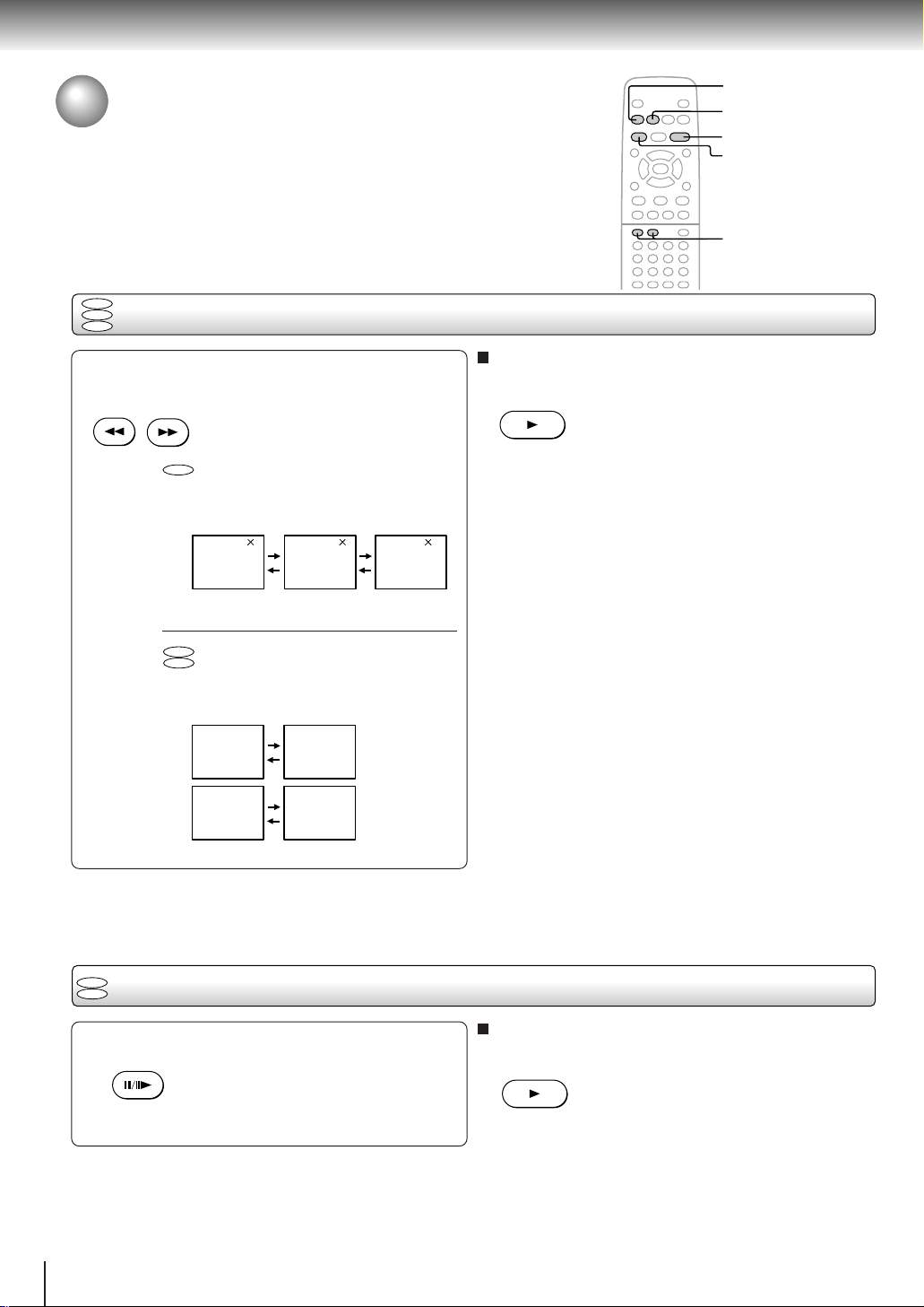
Playing in fast reverse or fast forward directions
CD
REV
FWD
PLAY
PAUSE/STEP
SLOW
Press REV or FWD during playback.
REV
FWD
REV: Fast reverse playback
FWD: F ast forward playback
DVD
Each time you press the REV or
FWD button, the playback speed
changes.
TV screen
x2 the normal
speed
VCD
CD
TV screen
2 830
x8 the normal
speed
x30 the normal
speed
Each time you press the REV or
FWD button, the two speeds
alternate.
FR1 FR2
FF1 FF2
Fast reverse
playback
Fast forward
playback
To resume normal playback
Press PLAY.
PLAY
Notes
• The DVD video player mutes sound and omits subtitles
during reverse and forward scan of DVD video discs.
However, the DVD video player plays sound during fast
forward or fast reverse play of audio CDs.
• The playback speed may differ depending on the disc.
DVD
Playing frame by frame
VCD
Press PAUSE/STEP during still playback.
PAUSE/STEP
Each time you press the PAUSE/
STEP button, the picture advances
one frame.
22
To resume normal playback
Press PLAY.
PLAY
Note
The sound is muted during frame by frame playback.
DVD
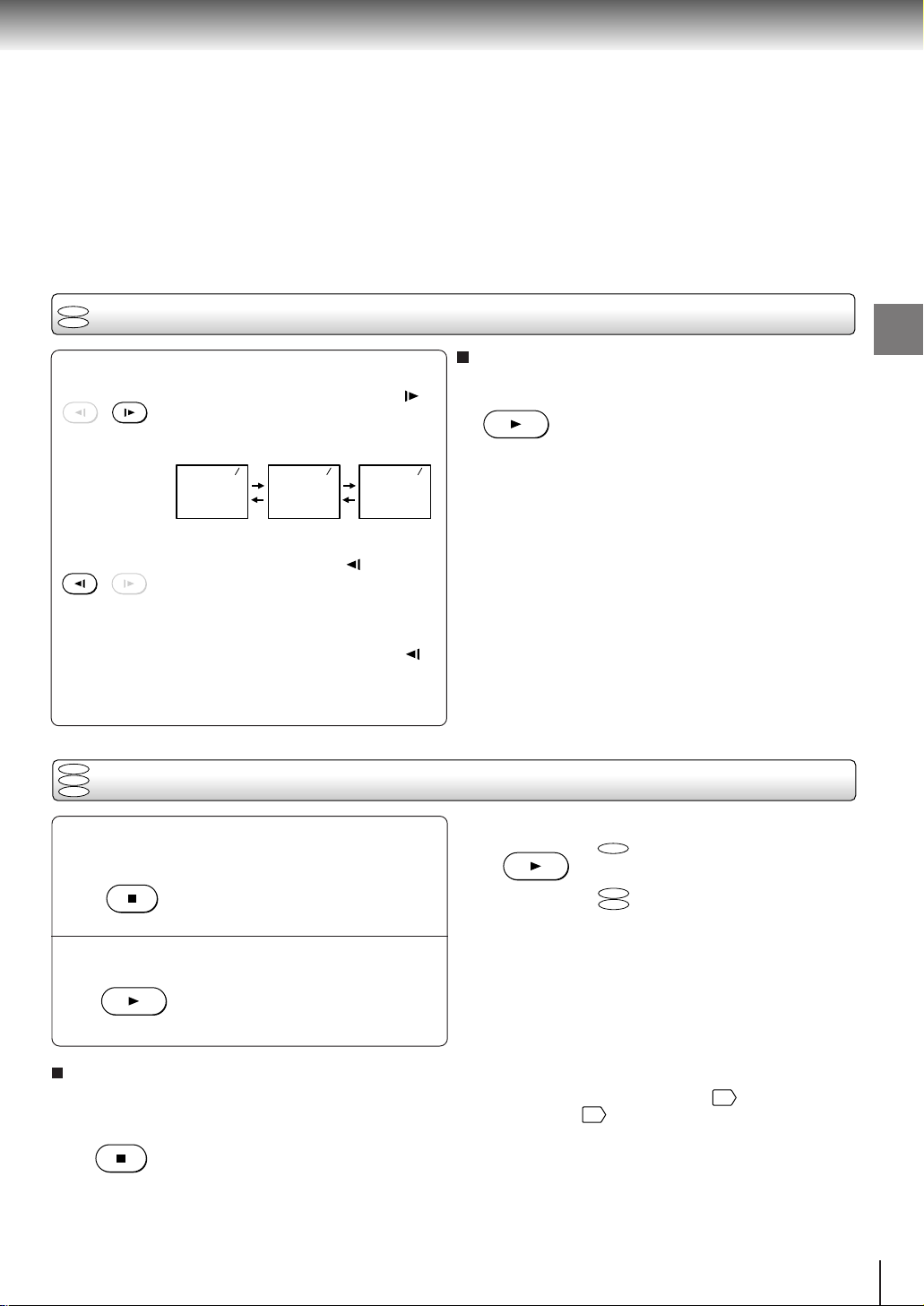
Playing in slow-motion
VCD
Press SLOW during playback.
SLOW
Each time you press the SLOW
Press PLAY.
button, the slow-motion speed
changes.
To resume normal playback
SLOW
TV screen
1/2 the normal
speed
214181
1/4 the normal
speed
1/8 the normal
speed
If you press the SLOW button
Notes
• The sound is muted during slow-motion playback.
• The playback speed may differ depending on the disc.
during playback, you can view the
picture in reverse slow-motion. (Only
when using a DVD video disc.)
Each time you press the SLOW
button, the slow-motion speed
changes.
DVD
VCD
Resuming playback from the same location
CD
2 Press PLAY.
Press STOP at the location where you
want to interrupt playback.
1
STOP
The DVD video player memorizes
the location where playback is
stopped.
• If you want to return to the beginning of a DVD video
Press PLAY.
2
PLAY
The DVD video player resumes
playback from the location where
you stopped playback.
To start playback from the beginning regardless
of the location where you stopped playback
1 Press STOP twice.
STOP
The DVD video player’s memory is
cleared.
Notes
• The DVD video player’s memory is also cleared when:
–you unplug the DVD video player from the wall outlet after
you stop playback.
–you change the parental lock setting 40 or select a disc
menu language 37.
–you open the disc tray for a disc which is played.
–you switch the discs by pressing the DISC SELECT button.
• There may be a difference in the location where playback
resumes depending on the disc.
• Settings you changed using the on-screen displays while the
DVD video player keeps a location in the memory may
function only after the memory is cleared.
PLAY
PLAY
DVD
Playback starts from the
beginning of the current title.
VCD
Playback starts from the
CD
beginning of the disc.
disc, open and close the disc tray once with the
OPEN/CLOSE (1/2) button for the disc you want to
play before pressing the PLAY button.
Basic playback
23
Basic playback
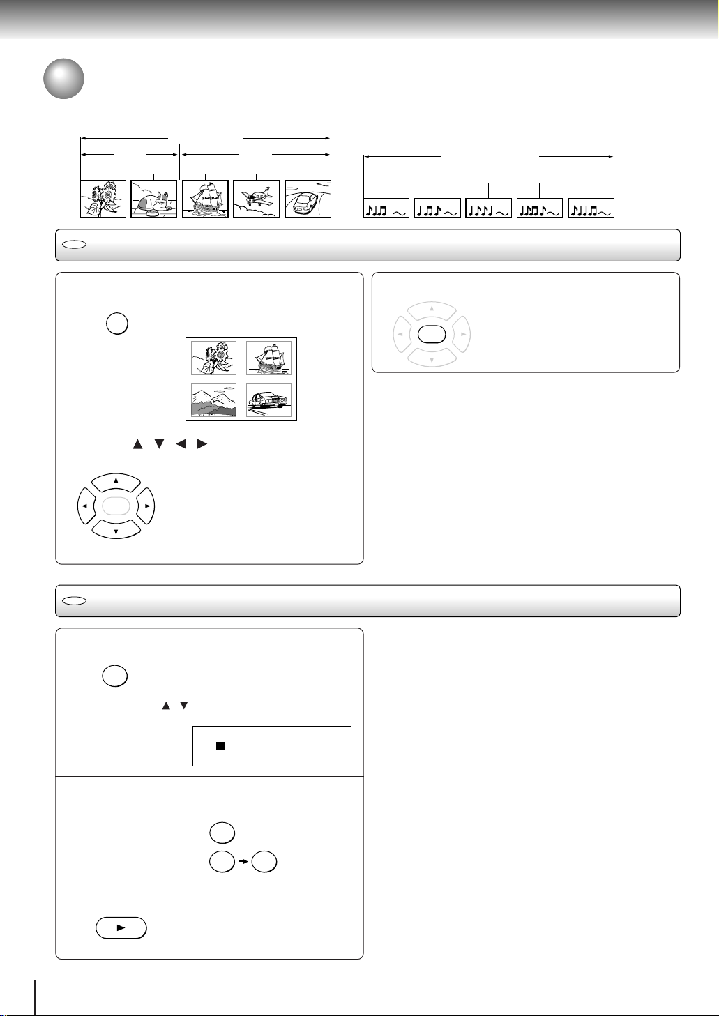
Locating a Specific Title, Chapter, or Track
Normally, DVD video discs are divided into titles, and the titles are sub-divided into chapters. VIDEO CDs and audio CDs
are divided into tracks. You can quickly locate any specific title, chapter, or track.
DVD video disc
Title 1 Title 2
Chapter 1 Chapter 2 Chapter 1 Chapter 2 Chapter 3
DVD
Locating a title using the top menu
Track 1
VIDEO CD/Audio CD
Track 2 Track 3 Track 4 Track 5
Press TOP MENU.
TOP MENU
1
The top menu appears on the TV
screen.
e.g.
TITLE 1
TITLE 3
TITLE 2
TITLE 4
Press / / / to select the title you
want.
2
If the titles in the top menu are
ENTER
DVD
Locating a title by entering the title number
assigned a number, you can directly
locate a specific title by pressing its
designated number with the number
buttons.
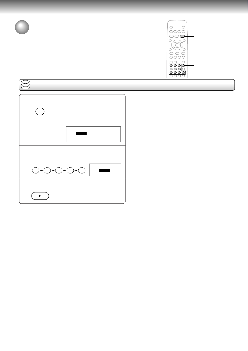
Press T.
SEARCH
1
T
Make sure that the space next to
“Title” is highlighted.
(You can shift the highlight using the
/ buttons.)
3
Notes
• The instructions above describe basic procedures which
may vary depending on the contents of the DVD video disc.
If different instructions appear on the TV screen, follow those
instructions.
• If you display the top menu during playback and press the
TOP MENU button again without selecting any title, the DVD
video player may resume playback from the point where you
first pressed the TOP MENU button (depending on the actual
DVD video disc.)
• This method of locating a title is available only on a disc that
contains a top menu.
• Instruction notes of discs may refer to the button that
displays the top menu as TITLE button.
Notes
• Pressing the CLEAR button resets the title and chapter
numbers. To clear the “Title” and “Chapter” display, press the
T button several times.
• This method of locating a title is available only on a disc that
contains title numbers.
Press ENTER.
Playback starts from chapter 1 of the
ENTER
selected title.
24
:
1
Title
:
hapter
C
1
Press the corresponding number
buttons for the title you want.
2
e.g. To select title 2
To select title 12
2
Press PLAY.
3
PLAY
Playback starts from chapter 1 of the
selected title.
21
TOP MENU
SKIP
PLAY
/ / /
ENTER
CLEAR
T
Number buttons
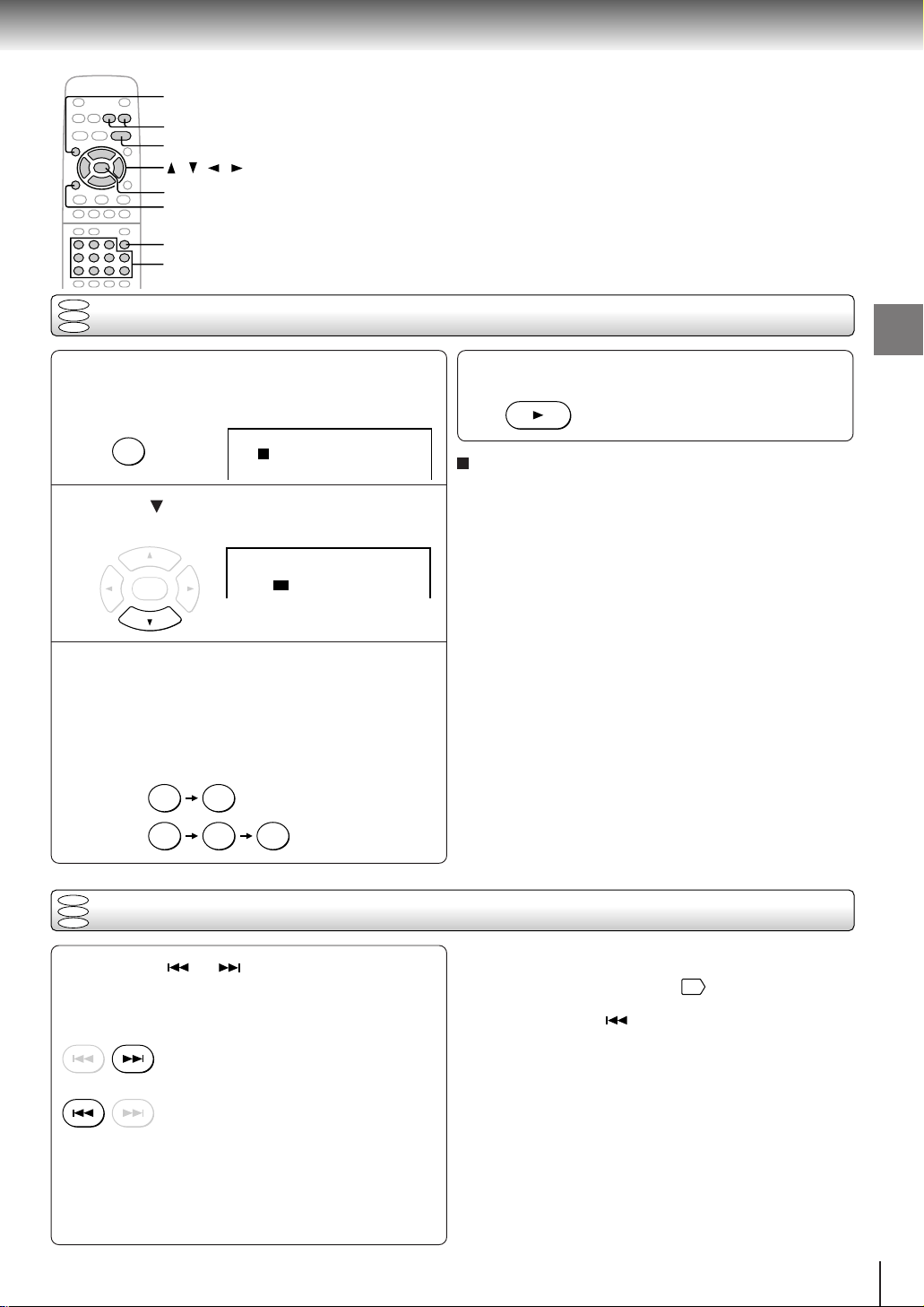
DVD
VCD
Locating a specific chapter or track directly
CD
Press T.
1
Skip steps 1 and 2 if you are using a VIDEO CD/
audio CD.
SEARCH
T
Title
C
hapter
:
1
:
1
Press to highlight the space next to
“Chapter.”
2
:
Title
1
:
C
hapter
ENTERENTERENTER
1
Press the corresponding number
buttons for the chapter or track you
3
want.
You can use the +10 button to select numbers
from 10 through 99.
e.g. To select chapter or track 25
52
or
+10 +10
5
Press PLAY.
4
Note
Pressing the CLEAR button resets the title and chapter
numbers. To clear the “Title” and “Chapter” display, press the T
button several times.
PLAY
Playback starts from the selected
chapter or track.
To select a title and chapter number at the same
time
Perform step 1, and enter a title number you want in the
space next to “Title” using the number buttons, then
perform steps 2 to 4.
Basic playback
DVD
VCD
Locating a specific chapter or track
CD
Press SKIP or repeatedly to display
the chapter or track number you want.
Playback starts from the selected chapter or track.
SKIP
SKIP
To locate succeeding chapters or tracks
Playback starts from the beginning of the
current chapter or track.
When you press twice, playback starts
from the beginning of the preceding
chapter or track.
Notes
• Some titles may not display chapter numbers.
• When you set “Title Stop” to “Off” 41, you can access
chapters in another title. If you go back to the preceding title
by pressing the SKIP button, the DVD video player
locates the first chapter of the title. When “Title Stop” is set
to “On,” you can access chapters only within the current title.
25
Advanced playback
2
1
3
Accessing a Specific Location Directly
You can access a specific location by entering its corresponding time (hours,
minutes, seconds).
DVD
VCD
Entering the time of the desired location
CD
Press T twice.
SEARCH
1
T
You may have to press further
depending on the disc. Press the
button repeatedly until the following
display appears.
:
:
Time
-- ---
Press the number buttons to enter the
time.
2
e.g.
1 2 5 3 0
Time
Press PLAY.
3
PLAY
Playback starts from the desired
location.
:
:
12530
Notes
• Some discs may not respond to this process.
• Some scenes may not be located precisely as you specified.
• This method for accessing specific locations is available
only within the current title of the DVD video disc or within
the current track of the VIDEO CD/audio CD.
26
 Loading...