

Page 1
OWNERS MANUAL
MANUEL DU PROPRIETAIRE
BETRIEBSANLEITUNG
MANUALE DEL PROPRIETARIO
MANUAL DEL PROPIETARIO
MANUAL DO UTILIZADOR
GEBRUIKSAANWIJZING
ПДЗГЙЕУ ЧСЗУЗУ
WIRED STAND ARD REMOTE CONTROLLER
For commercial use
RBC-AMT31E
Object Indoor Unit
Super Modular Multi System/
Super Heat Recovery System
<4-way Air Discharge Cassette Type>
MMU-AP0091H, AP0121H, AP0151H, AP0181H, AP0241H,
MMU-AP0271H, AP0301H, AP0361H, AP0481H, AP0561H
<2-way Air Discharge Cassette Type>
MMU-AP0071WH, AP0091WH, AP0121WH, AP0151WH, AP0181WH, AP0241WH, AP0271WH,
MMU-AP0301WH MMU-AP0481WH
<1-way Air Discharge Cassette Type>
MMU-AP0071YH, AP0091YH, AP0121YH, AP0151SH, AP0181SH, AP0241SH
<Concealed Duct Standard Type>
MMD-AP0071BH, AP0091BH, AP0121BH, AP0151BH, AP0181BH, AP0241BH, AP0271BH,
MMD-AP0301BH, AP0361BH, AP0481BH, AP0561BH
<Concealed Duct High Static Pressure Type>
MMD-AP0181H, AP0241H, AP0271H, AP0361H, AP0481H, AP0721H, AP0961H
<Under Ceiling Type>
MMC-AP0151H, AP0181H, AP0241H, AP0271H, AP0361H, AP0481H
<High Wall Type>
MMK-AP0071H, AP0072H, AP0091H, AP0092H, AP0121H, AP0122H, AP0151H, AP0181H, AP0241H
<Floor Standing Cabinet Type>
MML-AP0071H, AP0091H, AP0121H, AP0151H, AP0181H, AP0241H
<Floor Standing Concealed Type>
MML-AP0071BH, AP0091BH, AP0121BH, AP0151BH, AP0181BH, AP0241BH
<Floor Standing Type>
MMF-AP0151H, AP0181H, AP0241H, AP0271H, AP0361H, AP0481H, AP0561H
Pour usage commercial
Nur für gewerbliche Nutzung
Per uso commer ciale
Para uso comercial
Para uso comercial
Voor commercieel gebruik
Гйб емрпсйкЮ чсЮуз
(CHINA market only)
Digital Inverter Air Conditioner
<4-way Air Discharge Cassette Type>
RAV-SM560UT-E, SM800UT-E, SM1100UT-E, SM1400UT-E
RAV-SP1100UT-E
<Under Ceiling Type>
RAV-SM561CT-E, SM801CT-E, SM1101CT-E, SM1401CT-E
<Concealed Duct High Static Pressure Type>
RAV-SM561BT-E, SM801BT-E, SM1101BT-E, SM1401BT-E
(Super Digital Inverter)
SET
H
TEMP.
DATA
SETTING
TEST
UNIT No.
R.C. No.
CODE No.
ON / OFF
Page 2

ADOPTION OF NEW REFRIGERANT
This Air Conditioner is a new type which adopts
a new refrigerant HFC (R410A) instead of the
conventional refrigerant R22 in order to prevent
destruction of the ozone layer.
CAUTION
• Before using the remote controller (RBC-AMT31E), please read this Owner’ s Manual.
• For installation except oper ation of the remote controller, refer to the Installation Manual attached to the air
conditioner unit.
• To use this remote controller safely and correctly, read this Instruction Manual thoroughly before use for
full understanding.
• After you read this manual, be sure to keep it so that one who uses the remote controller can read this
manual anytime. If another person uses the remote controller, necessarily hand the Manual to him or her.
PRUDENCE
• Avant d’utiliser la télécommande (RBC-AMT31E), veuillez lire ce Mode d’emploi.
• Consultez le Manuel d’installation du climatiseur uniquement pour installer la télécommande, pas pour la faire fonctionner.
• Pour utiliser cette télécommande de façon correcte et sûre, lisez attentivement ce Mode d’emploi en entier.
• Lorsque vous avez fini de lire ce Mode d’emploi, rangez-le soigneusement pour pouvoir le consulter par la suite.
Si une autre personne doit utiliser la télécommande, remettez-lui ce Mode d’emploi.
VORSICHT
• Lesen Sie dieses Benutzerhandbuch, bevor Sie die Fernbedienung (RBC-AMT31E) benutzen.
• Einzelheiten zur Installation der Fernbedienung finden Sie in dem dem Klimagerät beiliegenden Installationshandbuch.
• Lesen Sie das Handbuch sorgfältig, so dass Sie den Inhalt verstehen, um die Fernbedienung sicher und korrekt zu bedienen.
• Bewahren Sie das Handbuch nach dem Lesen so auf, dass jeder, der die Fernbedienung benutzen will, Zugriff auf das Handbuch hat.
Will eine andere Person die Fernbedienung benutzen, händigen Sie ihr das Handbuch aus.
AVVERTENZA
• Prima di usare il telecomando (RBC-AMT31E), raccomandiamo la lettura di questo manuale d’istruzioni destinato al proprietario.
• Solo per l’installazione del telecomando , non per il funzionamento, fare riferimento al manuale di installazione fornito con il condizionatore d’aria.
• Per utilizzare il telecomando correttamente e in condizioni di sicurezza, leggere completamente questo Manuale d’istruzioni.
• Dopo aver letto questo manuale, conservarlo a portata di mano di altri che debbano poi usare il telecomando.
Se un’altra persona deve usare il telecomando, raccomandare la lettura del manuale.
PRECAUCIÓN
• Lea este Manual del propietario antes de utilizar el mando a distancia (RBC-AMT31E).
• Para conocer más detalles sólo acerca de la instalación del mando a distancia, consulte el Manual de instalación que se adjunta con el aparato de aire
acondicionado.
• Para utilizar este mando a distancia de manera correcta y segura, lea con atención este Manual de instrucciones antes de utilizarlo para asegurarse de
que entiende totalmente su funcionamiento.
• Después de leer este manual, asegúrese de guardarlo, de modo que cualquier persona que utilice el mando a distancia pueda leerlo en cualquier
momento. Si otra persona utiliza el mando a distancia, entréguele este Manual.
CUIDADO
• Antes de utilizar o controlador remoto (RBC-AMT31E), leia o presente Manual do Proprietário.
• Para pormenores acerca da instalação, excluindo o funcionamento, do controlador remoto, consulte o Manual de Instalação fornecido com o aparelho de
ar condicionado.
• Para utilizar este controlador remoto em segurança e correctamente, leia atentamente o presente Manual de Instruções antes da sua utilização para um
entendimento exaustivo.
• Depois da leitura do presente manual, guarde-o para que quem utilizar o controlador remoto o possa ler em qualquer altura.
Se outra pessoa utilizar o controlador remoto, faculte-lhe o Manual.
LET OP
• Lees voordat u de afstandsbediening (RBC-AMT31E) gaat gebruiken eerst deze gebruiksaanwijzing.
• Meer informatie over de installatie (dus niet over de werking) van de afstandsbediening vindt u in de installatiehandleiding bij de
airconditionerunit.
• Lees voor een veilig en correct gebruik van deze afstandsbediening deze handleiding aandachtig door.
• Bewaar deze handleiding, zodat u deze in de toekomst zonodig nogmaals kunt nalezen.
Overhandig de handleiding, als iemand anders de afstandsbediening gebruikt, aan deze persoon.
РСПУПЧЗ
Рсйн чсзуймпрпйЮуефе фп фзлечейсйуфЮсйп (RBC-AMT31E), рбсбкблпэме дйбвЬуфе бхфь фп ЕгчейсЯдйп ЧсЮузт.
Гйб фзн егкбфЬуфбуз, екфьт брь фз лейфпхсгЯб фпх фзлечейсйуфзсЯпх, деЯфе фп ЕгчейсЯдйп ЕгкбфЬуфбузт рпх еЯнбй рспубсфзмЭнп уфз мпнЬдб клймбфйумпэ.
Гйб нб чсзуймпрпйЮуефе бхфь фп фзлечейсйуфЮсйп ме буцблЮ фсьрп кбй ущуфЬ, дйбвЬуфе рспуекфйкЬ бхфь фп ЕгчейсЯдйп ЕгкбфЬуфбузт юуфе нб
кбфбнпЮуефе кблЬ фз лейфпхсгЯб фпх.
Бцпэ дйбвЬуефе бхфь фп егчейсЯдйп, цхлЬофе фп, юуфе нб мрпсеЯ бнЬ рЬуб уфйгмЮ нб фп дйбвЬуей кЬрпйпт рпх иб чсзуймпрпйЮуей фп фзлечейсйуфЮсйп.
Бн Энб Ьллп Ьфпмп чсзуймпрпйЮуей фп фзлечейсйуфЮсйп, дюуфе фпх бхфь фп ЕгчейсЯдйп.
(RBC-AMT31E)
Page 3
CONTENTS
SAFETY CAUTION.........................................................1
PARTS NAME OF REMOTE CONTROLLER .................2
CORRECT USAGE.........................................................4
TIMER OPERATION .......................................................5
SOMMAIRE
MESURES DE SECURITE ...........................................12
NOM DES PIECES DE LA TELECOMMANDE ............13
UTILISATION CORRECTE ...........................................15
FONCTIONNEMENT PAR MINUTERIE........................16
INHALT
SICHERHEITSHINWEISE ............................................23
TEILEBEZEICHNUNG DER FERNBEDIENUNG .........24
RICHTIGE HANDHABUNG ..........................................26
ZEITBETRIEB...............................................................27
INDICE
PRECAUZIONI DI SICUREZZA....................................34
NOME DELLE PARTI DEL TELECOMANDO...............35
USO CORRETTO..........................................................37
FUNZIONAMENTO CON TIMER ..................................38
ADJUSTMENT OF WIND DIRECTION...........................6
MAINTENANCE............................................................10
TROUBLESHOOTING ..................................................11
REGLAGE DU SENS DE SOUFFLAGE .......................17
ENTRETIEN ..................................................................21
DÉPANNAGE................................................................22
EINSTELLUNG DES LUFTSTROMS ...........................28
WARTUNG....................................................................32
FEHLERSUCHE ...........................................................33
REGOLAZIONE DELLA DIREZIONE DELL’ARIA .......39
MANUTENZIONE .........................................................43
RISOLUZIONE DEI PROBLEMI ...................................44
ITALIANO
CONTENIDO
PRECAUCIONES DE SEGURIDAD .............................45
DESCRIPCIÓN DE LOS BOTONES DEL
CONTROL REMO TO ....................................................46
UTILIZACIÓN CORRECTA ...........................................48
ÍNDICE
PRECAUÇÃO DE SEGURANÇA .................................56
NOME DAS PEÇAS DO CONTROLADOR REMOTO ..57
UTILIZAÇÃO CORRECTA............................................59
OPERAÇÃO DO TEMPORIZADOR ..............................60
INHOUD
AANDA CHTSPUNTEN V OOR UW VEILIGHEID ..........67
BENAMING VAN DE ONDERDELEN VAN DE
AFSTANDSBEDIENING ...............................................68
CORRECT GEBRUIK ................................................... 70
РЕСЙЕЧПМЕНБ
РСПЦХЛБОЕЙУ ГЙБ ФЗН БУЦБЛЕЙБ ......................... 78
ПНПМБУЙБ ФМЗМБФЩН ФПХ ФЗЛЕЧЕЙСЙУФЗСЙПХ . 79
ПСИЗ ЧСЗУЗ ............................................................... 81
ЛЕЙФПХСГЙБ ЧСПНПДЙБКПРФЗ ................................ 82
FUNCIONAMIENTO DEL TEMPORIZADOR ................49
AJUSTE DE LA DIRECCIÓN DEL AIRE .....................50
MANTENIMIENTO ........................................................54
RESOLUCIÓN DE PROBLEMAS.................................55
REGULAÇÃO DA DIRECÇÃO DO VENTO ..................61
MANUTENÇÃO ............................................................65
RESOLUÇÃO DE PROBLEMAS..................................66
DE TIMER GEBRUIKEN ...............................................71
INSTELLEN VAN DE LUCHTSTROOMRICHTING ...... 72
ONDERHOUD...............................................................76
STORINGEN VERHELPEN ..........................................77
СХИМЙУЗ ФЗУ КБФЕХИХНУЗУ ФПХ БНЕМПХ ......... 83
УХНФЗСЗУЗ ................................................................. 87
БНФЙМЕФЩРЙУЗ РСПВЛЗМБФЩН.............................. 88
ESPAÑOLPORTUGUÊSЕЛЛЗНЙКБ FRANCAISDEUTSCHNEDERLANDS ENGLISH
Page 4
SAFETY CAUTION
• Please read this “Safety Cautions” thoroughly before installation to install the air conditioner
correctly.
• The important contents concerned to the safety are described in the “Safety Cautions”.
Be sure to keep them. For Indications and their meanings, see the following description.
n Explanation of indications
W ARNING
Indicates possibilities that a death or serious injury of personnel is caused by an incorrect handling.
CAUTION
Indicates contents that an injury (∗1) or property damage (∗2) only may be caused when an incorrect
work has been ex ecuted.
∗1 : “Injury” means a hurt, a burn, or an electric shock which does not require hospitalization or a long-term
going to the hospital.
∗2 : “Property damage” means an enlarged damage concerned to property, or breakage of materials.
• After installation work has finished, check there is no trouble by a test operation, and explain
using method and maintenance method to the customers based on the Owner’s Manual.
Please ask the customers to keep this Installation Manual together with the Owner’s Manual.
• Make sure to ask the qualified installation professional in electric work to install the air conditioner.
If the air conditioner is inappropriate installed by yourself, it may cause water leak, electric shock, fire , and
so on.
• A person qualified for the electric work should deal with the electric construction conforming
to the regulations of the local electric company and the Installation Manual.
Be sure to use the exclusive circuit.
If there is capacity shortage of the power supply circuit or incomplete installation, a fire or an electric shock
is caused.
• For wiring, use the specified wires and connect them securely so that external force of wire
does not transmit to the terminal connecting section.
If connection or fixing is incomplete, a fire, etc may be caused.
• For the products sold separately, be sure to use those specified by us.
Be sure to use the products sold separately which are specified by us; otherwise a fire, an electric shock, or
water leak may be caused. Moreover ask an expert to install the air conditioner.
• When you notice something abnormal with the air conditioner (smells like something scorching, poor cooling, etc.), immediately turn off the main switch, the circuit breaker, from the
mains to stop the air conditioner, and contact the dealer.
If the air conditioner is continuously operated with something abnormal, it may cause machine failure,
electric shock, fire, and so on.
• Do not touch the switches with the wet hands.
Otherwise an electric shock may be caused.
• When cleaning the air conditioner, be sure to stop the operation and turn off the power switch.
Otherwise an injury may be caused because the fan rotates in high speed inside of the air conditioner.
1
Page 5
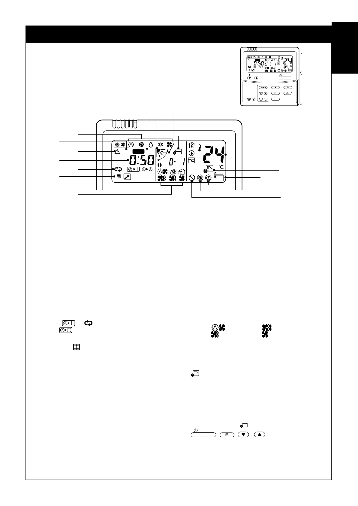
PARTS NAME OF REMOTE CONTROLLER
Display section
In the display example, all indicators are displayed for the explanation.
In reality only, the selected contents are indicated.
• When turning on the leak breaker at the first time, [SET DATA] flashes on
the display part of the remote controller. While this display is flashing, the
model is being automatically confirmed. Accordingly, wait for a while after
[SET DATA] display has disappeared, and then use the remote controller.
78 9
2
1
4
3
5
SET
H
DATA
SETTING
TEST
UNIT No.
R.C. No.
CODE No.
6
15
1
SET DAT A display
Displayed during setup of the timer.
2
Operation mode select display
The selected operation mode is displayed.
3
CHECK display
Displayed while the protective device works or
a trouble occurs.
4
Timer time display
Time of the timer is displayed.
(When a trouble occurs, the check code is
displayed.)
5
Timer SETIN setup display
When pushing the Timer SETIN button, the
display of the timer is selected in order of
[OFF]
[ON]
6
Filter display
If “FILTER ” is displayed, clean the air filter.
7
TEST run display
Displayed during a test run.
8
Flap position display
(for 4-W ay Air Discharge Cassette T ype
and Under Ceiling Type model only)
Displays flap position.
9
SWING display
Displayed during up/down movement of the
flap.
10
Set up temperature display
The selected set up temp. is displayed.
11
Remote controller sensor display
Displayed while the sensor of the remote
controller is used.
→ [OFF] repeat OFF timer →
→ No display.
12
PRE-HEAT display
(for Heat-pump model only)
Displayed when the heating operation starts or
defrost operation is carried out.
While this indication is displayed, the indoor fan
stops or the mode enters in LOW.
13
Operation ready display
Displayed when cooling or heating operation is
impossible because the outdoor temperature goes
out of the operable range.
14
No function display
Displayed if there is no function even if the button is
pushed.
15
Air volume select displa y
The selected air volume mode is displayed.
(AUTO)
(MED.) (LOW)
In the Concealed Duct High Static Pressure type
models, [HIGH] only is displayed for the air speed.
16
Mode select control display
Displayed when pushing “Operation mode select
” button while the operation mode is fixed to
heating or cooling by the system manager of the air
conditioner.
17
Central control display
Displayed when using the remote controller together
with the central control remote controller, etc.
If Remote controller is prohibited at the
centralcontrol side,
ON / OFF
the change is not accepted.
(The contents available to be set up on the remote
controller differ according to the central control
mode. For details, refer to Owner’s Manual of the
central control remote controller.)
,
DATA
SET
TEST
SETTING
H
TEMP .
TIMER SET
FILTER
TEST
RESET
10
11
12
(HIGH)
MODE
flashes when operating
, / buttons and
UNIT No.
R.C. No.
CODE No.
ON / OFF
FAN
MODE
SWING/FIXTIME
VENT
UNITSET CL
Display
section
Operation
section
ENGLISH
17
16
13
14
2
Page 6

Operation section
ON / OFF
Push each button to select a desired operation.
This remote controller can operate the maximum 8 indoor units.
• The details of the operation needs to be set up once, afterward, the air conditioner can be used by pushing
ON / OFF
button only.
1
7
TEMP.
10
2
FIL TER
TEST
RESET
5
3
1
Air volume select button
Selects the desired air volume mode.
The Concealed Duct High Static Pressure type
models cannot be operated.
2
Timer set button
TIMER SET button is used when the timer is
set up.
3
Check button
The CHECK button is used for the check
operation. During normal operation, do not
use this button.
4
Fan button
FAN button is used when a fan which is sold on
the market or etc. is connected.
• If is displayed on the remote controller
when pushing the FAN button, a fan is not
connected.
TIMER SET
ON / OFF
8
FAN
SWING/FIXTIME
MODE
VENT
9
4
UNITSET CL
6
7
Operation lamp
Lamp is lit during the operation. Lamp is off
when stopped.
Although it flashes when operating the protection device or abnormal time.
8
When the button is pushed, the operation
starts, and it stops by pushing the button
again.
When the operation has stopped, the operation
lamp and all the displays disappear.
9
Operation select button
Selects desired operation mode.
10
Set up temperature button
Adjusts the room temperature.
Set the desired set temperature by pushing
button
or .
5
Filter reset button
Resets (Erases) “FILTER ” display.
6
Wind direction and Swing
UNIT
:
If the multiple indoor units are operated by only
one remote controller, select the units when
the air direction is adjusted.
SWING/FIX
:
Set up the auto swing and angle of the flap.
• This function is not provided to Concealed
Duct Standard Type, High Static Pressure
Type, Floor standing Cabinet Type, Floor
Standing Concealed Type, or Slim Duct Type.
Remote controller sensor
Usually the TEMP. sensor of the indoor unit senses
the temperature. The temperature on the surrounding of the remote controller can also be sensed.
For details, contact the dealer from which you have
purchased the air conditioner.
• In case that one remote controller controls the
multiple indoor units, the setup operation is
unavailab le in group control.
3
Page 7

CORRECT USAGE
When you use the air conditioner f or the first time or when you change the SET DATA value, follow the procedure below. From the next time, the operation displayed on the remote controller will start by pushing the
ON / OFF
button only.
Preparation
Turn on the main power switch and/or the leakage breaker.
• When the power supply is turned on, a partition line is displayed on the display part of the remote controller.
After the power supply is turned on, the remote controller does not accept an operation for appro x. 1 minute,
*
but it is not a f ailure.
REQUIREMENT
• While using the air conditioner, operate it only with
switch and the leak breaker.
• Do not turn off the leak breaker while the air conditioner is used.
• Turn on the leak breaker 12 hours or more before start of operation after the air conditioner has stopped
for a long time.
ON / OFF
button without turning off the main power
TEMP.
ON / OFF
1
4
TIMER SET
FIL TER
TEST
RESET
1
Push
The operation lamp goes on, and the operation starts.
2
Select an operation mode with the
One push of the button, and the displa y
changes in the order shown on the right.
•“DRY mode” function is not provided to
Concealed Duct High Static Pressure Type.
3
Select air volume with
One push of the button, and the display changes in the order shown on the right.
• When air volume is “AUTO ”, air volume diff ers according to the room temper ature .
• In DRY mode, “AUTO ” is displayed and the air volume is LOW.
• In heating operation, if the room temperature is not heated sufficiently with volume “LOW ” operation,
select “MED. ” or “HIGH ” operation.
• The temperature which the temperature sensor detects is one near the air inlet of the indoor unit.
Therefore it slightly diff ers from the room temperature according to the installation status. The setup
value is a criterion of the room temperature. (Automatic air speed cannot be selected in FAN mode.)
• Air volume of function is not provided to “Concealed Duct High Static Pressure Type” but air speed
“HIGH ” only is display ed.
ON / OFF
button.
FAN
button.
MODE
button.
FAN
SWING/FIXTIME
UNITSET CL
MODE
VENT
HEAT DRY COOL FANAUTO
AUTO
3
2
(Dehumidity)
LOW MED. HIGH
4
Determine the set up temperature by pushing the “TEMP. ” or “TEMP. ” button.
Stop
Push
The operation lamp goes off, and the operation stops .
ON / OFF
button.
4
Page 8

TIMER OPERATION
A type of timer operation can be selected from the following three types.
OFF timer : The operation stops when the time of timer has reached the set time .
Repeat OFF timer : Every time, the operation stops after the set time has passed.
ON timer : The operation starts when the time of timer has reached the set time.
Timer operation
TEMP.
TIMER SET
FAN
ON / OFF
MODE
1
SWING/FIXTIME
FIL TER
TEST
RESET
3
4
1
Push TIMER SET button.
• The timer display (type) changes for every
push of the button.
• SET DATA and display flashes.
2
TIMER SET
Push
Every pushing b utton, the setup time increases in the unit of 0.5 hr (30 minutes).
For the setup time above (24 hr), time increases in the unit of 1 hr.
The maximum setup time is (168 hr).
On the remote controller, the setup time is displayed with numerals for 0.5 hr to 23.5 hr (*1), and time
over 24 hr (*2) is displayed by No. of days and time.
Every pushing b utton, the setup time is decreased in the unit of 0.5 hr (30 min utes)
(From 0.5 hr to 23.5 hr) or in the unit of 1 hr (From 24 hr to 168 hr).
to select “SET TIME”.
UNITSET CL
VENT
2
OFF
(OFF timer) (Repeat OFF timer)
OFF ON
No display
(ON timer)
Display example of remote controller
• Case of 23.5 hr (*1) • Case of 34 hr (*2)
SETTING SETTING
Days ∗a Times ∗b
3
Push SET button.
• SET DATA display disappears and display goes on.
(When ON timer is activated, time is displayed, and after time of the timer has been up, displays other
than ON disappear.)
∗a: Represents a day (24 hr).
∗b: Represents 10 hours
(Total 34 hours).
Cancel of timer operation
4
Push CL button.
• TIMER display disappears.
NOTICE
• When the operation stops after the timer reached the preset time, the Repeat OFF timer resumes the
operation by pushing
the set time.
ON / OFF
button and stops the operation after the time of the timer has reached
5
Page 9

ADJUSTMENT OF WIND DIRECTION
To increase the cooling or heating effect, be sure to use the discharge flap in the different
directions in cooling or heating operation.
As the characteristics of the air, the cold air accumulates at lower side and hot air at upper side, respectively.
CAUTION
Set the louver horizontally in cooling operation.
If cooling operation is performed with downward discharge , the surface of the discharge port or louver will
be wet with dew, and dewdrop ma y fall down.
REQUIREMENT
• If heating operation is performed with horizontal discharge, unev enness of temper ature may increase in
the room.
4-way Air Discharge Cassette, Under Ceiling Type
• While the air conditioner stops, the discharge flap automatically directs downward.
• While the air conditioner is in ready status for heating,
the discharge flap directs upward.
The swinging operation starts after heating ready status
has been cleared, but “SWING
remote controller even if the status is ready to heating.
” is displayed on the
[In Cooling operation]
Use the discharge flap with horizontal set point.
[In Heating operation (For Heat-pump model only)]
Use the discharge flap with downward set point.
6
Page 10

How to set up the air direction
SWING/FIX
Push
1
Every pushing the button, the air direction changes.
button.
In Heating operation
Set the air outlet flap downward.
If directing it upward, the hot air may not come to the f oot.
In Cooling / Dry operation
Set the air outlet flap upward.
If directing it downward, the dew may fall on near the air discharge port or it drips.
How to start swinging
Initial setup
Initial setup
Push
SWING/FIX
button.
2
Set direction of the air outlet flap to the
lowest position and then push
SWING/FIX
again.
• [SWING ] is displayed and the air direction
automatically changes upward/downward.
In case when one remote controller controls
the multiple indoor units, each indoor unit can
be selected and its air direction can be set up.
How to stop swinging
3
4
SWING/FIX
Push
button again during swinging of
the air outlet flap.
• The air outlet flap can be stopped at the
desired position. After then the air direction
can be again set up from the uppermost
position by pushing
SWING/FIX
button.
* While the air outlet flap is set downward in
cooling/drying operation, it does not stop.
If stopping the air outlet flap which directs
downward during swinging, it stops after
moving to the 3rd position from the top
position.
UNIT
• To set up the air direction individually, push
UNIT
button to display each indoor unit No. in
a group control. Then set up the air direction to
a displayed indoor unit.
• If there is no display, all the indoor units can be
operated collectively.
• Every pushing
UNIT
button, the displa y
exchanges as shown in the figure.
button
TEMP.
FAN
SWING/FIXTIME
UNITSET CL
FIL TER
RESET
TIMER SET
TEST
1, 2, 3 4
In FAN operation
Initial setup
Display when stopping the swing
Fan/Heat
operation
Unit No. 1-1No display Unit No. 1-2
Unit No. 1-4 Unit No. 1-3
In all modes
ON / OFF
MODE
VENT
Series of
operation
Cool/Dry
operation
7
Page 11

According to the shape or arrangement of the room, the cold air and hot air can be discharged for two directions or three directions. For details , contact the dealer.
INFORMATION
• If cooling operation is performed with downward discharge, dew may fall on surface of the cabinet or the
horizontal flap resulted in dripping.
• If heating operation is performed with horizontal discharge, unev enness of temper ature may increase in
the room.
• Do not move the horizontal flap directly with hands; otherwise a trouble is caused. Select direction of the
horizontal flap using flap operation switch on the remote controller. The horizontal flap does not stop
immediately even if the switch is pushed. Adjusting the stop position, push the switch.
2-way Air Dischar ge Cassette, 1-way Air Discharge Cassette, Floor Standing, High Wall Type
[In Cooling operation]
Use the air outlet flap with horizontal set point.
[In Heating operation (For Heat-pump model only)]
Use the air outlet flap with downward set point.
Setup of air direction and swinging
Push
SWING/FIX
button during operation.
1
• [SWING ] is displayed and the air direction automatically changes upward/downward.
In case when one remote controller controls the multiple indoor units, each indoor unit can be selected
and its air direction can be set up.
2
Push
SWING/FIX
button again during swinging of the air
TEMP.
outlet flapp.
• The air outlet flap can be stopped at the desired
position.
UNIT
3
• To set up the air direction individually, push
UNIT
FILTER
RESET
TIMER SET
TEST
FAN
SWING/FIXTIME
UNITSET CL
button to displa y each indoor unit No. in a group
control. Then set up the air direction to a displayed
indoor unit.
1, 2 3
• If there is no display, all the indoor units can be operated collectively.
• Every pushing
shown in the figure.
UNIT
button, the display exchanges as
Unit No. 1-4 Unit No. 1-3
Unit No. 1-1No display Unit No. 1-2
1-way Air Discharge Cassette Type
Adjustment of air direction upward/downward
[In Cooling operation]
In cooling operation, use the air outlet flap with horizontal set point so that the
cold air diffuses in whole room.
ON / OFF
MODE
VENT
[In Heating operation (For Heat-pump model only)]
In heating operation, use the air outlet flap with downward set point so that
the hot air blows at the f oot.
Adjustment of air direction rightward/leftward
To change the discharge direction to right or left side, set the vertical grille
inside of the air outlet flap to the desired direction.
Setup of air direction and swinging
Refer to description of “2-way Air Discharge Cassette Type”.
8
Page 12

Right/Left air direction adjustment
To change the air outlet direction to right or left side, set the vertical flap inside of the horizontal flap to the
desired direction.
INFORMATION
• If cooling operation is performed with downward discharge,
dew may fall on surface of the cabinet or the horizontal flap
resulted in dripping.
• If heating operation is performed with horizontal discharge,
unevenness of temper ature may increase in the room.
High Wall T ype
Adjustment of air direction upward/downward
[In Cooling operation]
In cooling operation, use the horizontal flap with horizontal set point
so that the cold air diffuses in whole room.
[In Heating operation (For Heat-pump model only)]
In heating operation, use the horizontal flap with downward set point
so that the hot air blows at the foot.
REQUIREMENT
• If cooling operation is performed with downward air outlet, de w
may fall on surface of the cabinet or the horizontal flap resulted
in dripping.
• If heating operation is performed with horizontal air outlet,
unevenness of temperature may increase in the room.
• Do not move the horizontal flap directly with hands; otherwise a
trouble is caused. Select direction of the horizontal flap using
SWING/FIX
switch on the remote controller. The horizontal flap does
not stop immediately even if the switch is pushed. Adjusting the
stop position, push the switch.
Adjustment of air direction rightward/leftward
To change the air outlet direction to right or left side, set the vertical
flap inside of the horizontal flap to the desired direction.
Setup of air direction and swinging
Refer to description of “2-way Air Discharge Cassette Type”.
9
Page 13

Floor Standing Type
Adjustment of air direction upward/downward
[In Cooling operation]
In cooling operation, move the flap with hands and use it with horizontal air outlet
point so that the cold air diffuses in whole room.
[In Heating operation (For Heat-pump model only)]
In heating operation, move the flap with hands and use the horizontal flap with
downward set point so that the hot air blows at the foot.
Adjustment of air direction rightward/leftward
[In case of using unsymmetrical air directions]
Lift up the vertical flap lightly, direct it to w ard the desired
direction, and lower it.
In this case, do not use the Swing function.
2
1
In this case, do not use the
swing function.
MAINTENANCE
Cleaning of air filter
• When [FILTER] is displa yed on the remote controller, maintain the air filter.
• Clogging of air filter decreases cooling/heating effect.
DATA
SET
SETTING
FILTER
RESET
H
TEMP.
TEST
FILTER display
Notifies the time to clean the air filter.
FILTER reset
Push the FILTER switch after cleaning.
“FILTER” display disappears.
TEST
TIMER SET
UNIT No.
R.C. No.
SWING/FIXTIME
UNITSET CL
FAN
CODE No.
ON / OFF
MODE
VENT
WARNING
Be sure to turn off the main power switch prior to the maintenance.
• Please do not intend to do the daily maintenance and/or Air Filter cleaning by yourself.
Cleaning of the air filter and other parts of the air filter involves dangerous work in high places, so be
sure to have a service person do it. Do not attempt it yourself .
10
Page 14

TROUBLESHOOTING
T
T
Confirmation and check
When a trouble occurred in the air conditioner, the
check code and the indoor unit No . appear on the
display part of the remote controller.
The check code is only displayed during the operation.
If the display disappears, operate the air conditioner
according to the following “Confirmation of error
history” for confirmation.
Confirmation of error history
When a trouble occurred on the air conditioner, the
trouble history can be confirmed with the following
procedure. (The trouble history is stored in memory
up to 4 troubles.)
The history can be confirmed from both operating
status and stop status.
2
CODE No.
UNIT No.
R.C. No.
Check code Indoor unit No. in which
TEMP.
TIMER SET
FILTER
TEST
RESET
an error occurred
ON / OFF
FAN
SWING/FIXTIME
UNITSET CL
MODE
VENT
Procedure
1
2
3
Description
When pushing
seconds or more, the following display appears.
If [Service check] is displayed, the mode enters in the
trouble history mode.
• [01 : Order of trouble history] is displayed in CODE No.
window.
• [Check code] is displayed in CHECK window.
• [Indoor unit address in which an error occurred] is
displayed in UNIT No.
Every pushing of , button used to set temperature, the trouble history stored in memory is
displayed in order.
The numbers in CODE No. indicate CODE No. [01] (latest) → [04] (oldest).
CAUTION
Do not push
SET
CL
TES
and
button because all the trouble history of the indoor unit will be deleted.
buttons at the same time for 4
UNIT No.
R.C. No.
CODE No.
1
3
After confirmation, push
TES
button to return to the usual display.
1. Check the troubles according to the abov e procedure .
2. Ask an authorized dealer or qualified service (maintenance) professional to repair or maintain the air
conditioner .
3. More details of the service code are explained in Service Manual.
11
Page 15

EH99923001
 Loading...