

Page 1
FILE NO. A04-003
SERVICE MANUAL
R410A
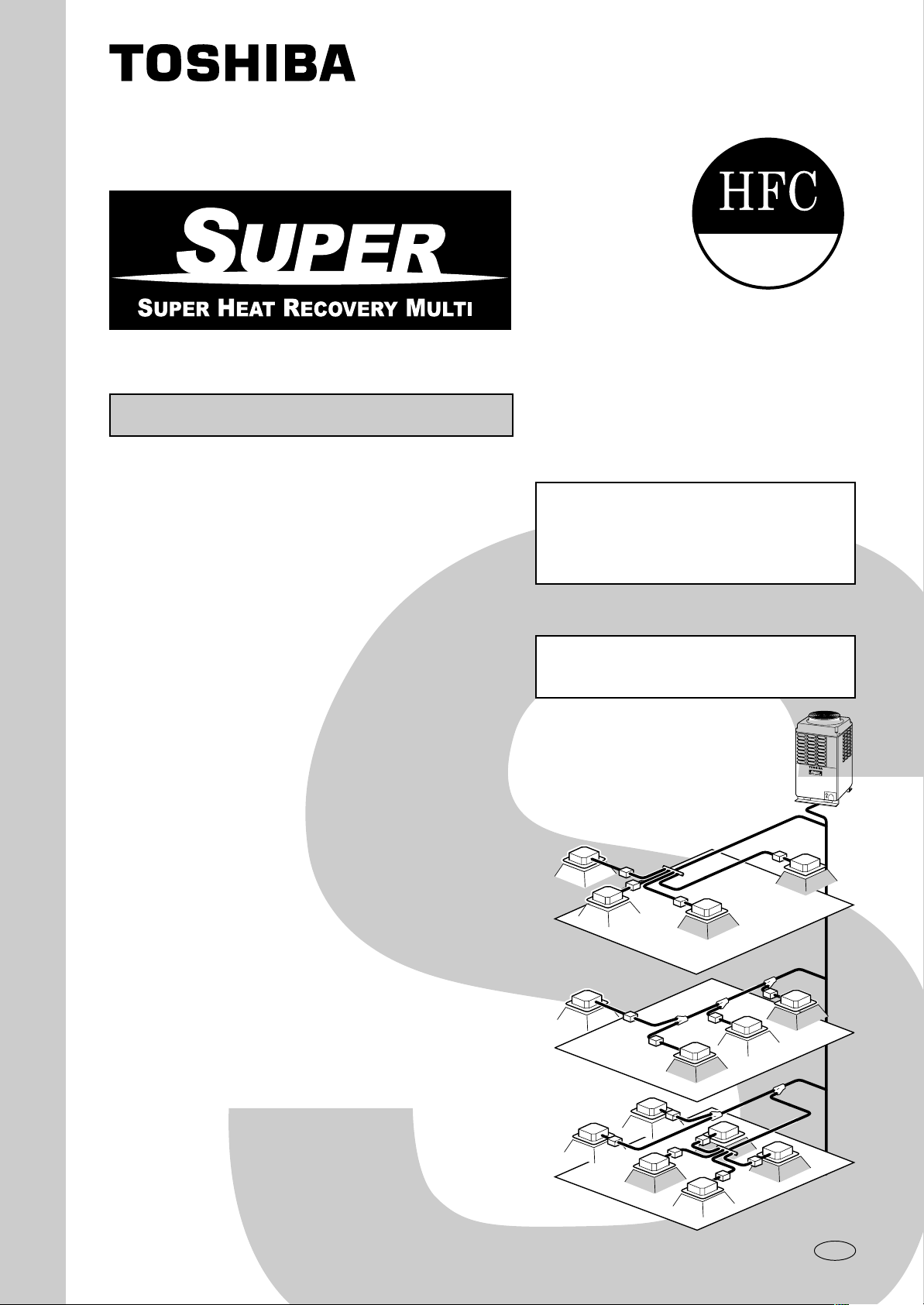
System air conditioner
The indoor unit in Super Heat Recovery Multi System is common to one in Super Modular Multi System air conditioner.
Therefore refer to the service manuals for A03-009, A03-010, and A03-011 separately issued.
Heat Recovery Type
Indoor Unit
<4-way Air Discharge Cassette Type>
MMU-AP0091H, AP0121H, AP0151H,
MMU-AP0181H, AP0241H, AP0271H,
MMU-AP0301H, AP0361H, AP0481H
MMU-AP0561H
<2-way Air Discharge Cassette Type>
MMU-AP0071WH, AP0091WH, AP0121WH,
MMU-AP0151WH, AP0181WH, AP0241WH,
MMU-AP0271WH, AP0301WH, AP0481WH*
* CHINA market only
<1-way Air Discharge Cassette Type>
MMU-AP0071YH, AP0091YH, AP0121YH,
MMU-AP0151SH, AP0181SH, AP0241SH
<Concealed Duct Standard Type>
MMD-AP0071BH, AP0091BH, AP0121BH,
MMD-AP0151BH, AP0181BH, AP0241BH,
MMD-AP0271BH, AP0301BH, AP0361BH,
MMD-AP0481BH, AP0561BH
<Concealed Duct High Static Pressure Type>
MMD-AP0181H, AP0241H, AP0271H,
MMD-AP0361H, AP0481H
Outdoor Unit
<Inverter Unit>
MMY-MAP0801FT8
MMY-MAP1001FT8
MMY-MAP1201FT8
Flow Selector Unit (FS unit)
RBM-Y1121FE
RBM-Y1801FE
<Under Ceiling Type>
MMC-AP0151H, AP0181H, AP0241H,
MMC-AP0271H, AP0361H, AP0481H
<High Wall Type>
MMK-AP0071H, AP0091H, AP0121H,
MMK-AP0151H, AP0181H, AP0241H
<Floor Standing Cabinet Type>
MML-AP0071H, AP0091H, AP0121H,
MML-AP0151H, AP0181H, AP0241H
<Floor Standing Concealed Type>
MML-AP0071BH, AP0091BH, AP0121BH,
MML-AP0151BH, AP0181BH, AP0241BH
<Floor Standing Type>
MMF-AP0151H, AP0181H, AP0241H,
MMF-AP0271H, AP0361H, AP0481H,
MMF-AP0561H
PRINTED IN JAPAN, Sep, 2004 ToMo
Page 2
WARNINGS ON REFRIGERANT LEAKAGE
Check of Concentration Limit
The room in which the air conditioner is to be
installed requires a design that in the event of
refrigerant gas leaking out, its concentration will
not exceed a set limit.
The refrigerant R410A which is used in the air
conditioner is safe, without the toxicity or
combustibility of ammonia, and is not restricted by
laws to be imposed which protect the ozone layer.
However, since it contains more than air, it poses the
risk of suffocation if its concentration should rise
excessively. Suffocation from leakage of R410A is
almost non-existent. With the recent increase in the
number of high concentration buildings, however, the
installation of multi air conditioner systems is on the
increase because of the need for effective use of floor
space, individual control, energy conservation by
curtailing heat and carrying power etc.
Most importantly, the multi air conditioner system is
able to replenish a large amount of refrigerant
compared with conventional individual air conditioners.
If a single unit of the multi conditioner system is to be
installed in a small room, select a suitable model and
installation procedure so that if the refrigerant
accidentally leaks out, its concentration does not
reach the limit (and in the event of an emergency,
measures can be made before injury can occur).
In a room where the concentration may exceed the
limit, create an opening with adjacent rooms, or install
mechanical ventilation combined with a gas leak
detection device.
The concentration is as given below.
Total amount of refrigerant (kg)
Min. volume of the indoor unit installed room (m³)
≤ Concentration limit (kg/m³)
The concentration limit of R410A which is used in multi
air conditioners is 0.3kg/m³.
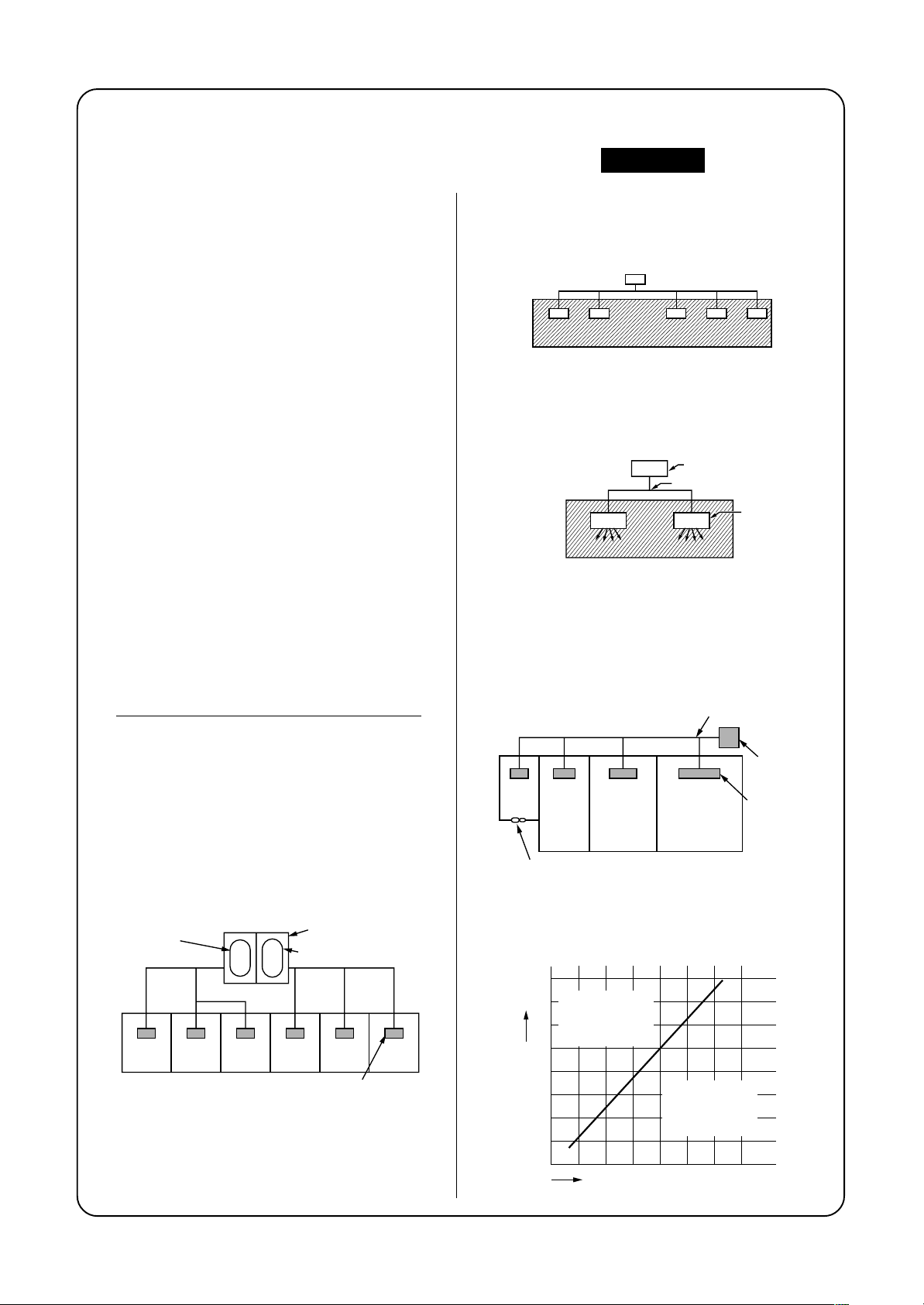
NOTE 1 :
If there are 2 or more refrigerating systems in a single
refrigerating device, the amounts of refrigerant should
be as charged in each independent device.
e.g., charged
amount (10kg)
Room A Room B Room C Room D Room E Room F
For the amount of charge in this example:
The possible amount of leaked refrigerant gas in
rooms A, B and C is 10kg.
The possible amount of leaked refrigerant gas in
rooms D, E and F is 15kg.
Outdoor unit
e.g.,
charged amount (15kg)
Indoor unit
Important
NOTE : 2
The standards for minimum room volume are as
follows.
(1) No partition (shaded portion)
(2) When there is an effective opening with the
adjacent room for ventilation of leaking refrigerant
gas (opening without a door, or an opening 0.15%
or larger than the respective floor spaces at the
top or bottom of the door).
Outdoor unit
Refrigerant piping
Indoor unit
(3) If an indoor unit is installed in each partitioned
room and the refrigerant tubing is interconnected,
the smallest room of course becomes the object.
But when a mechanical ventilation is installed
interlocked with a gas leakage detector in the
smallest room where the density limit is exceeded,
the volume of the next smallest room becomes the
object.
Refrigerant piping
Outdoor unit
Very
small
room
Small
room
Mechanical ventilation device - Gas leak detector
Medium
room
Large room
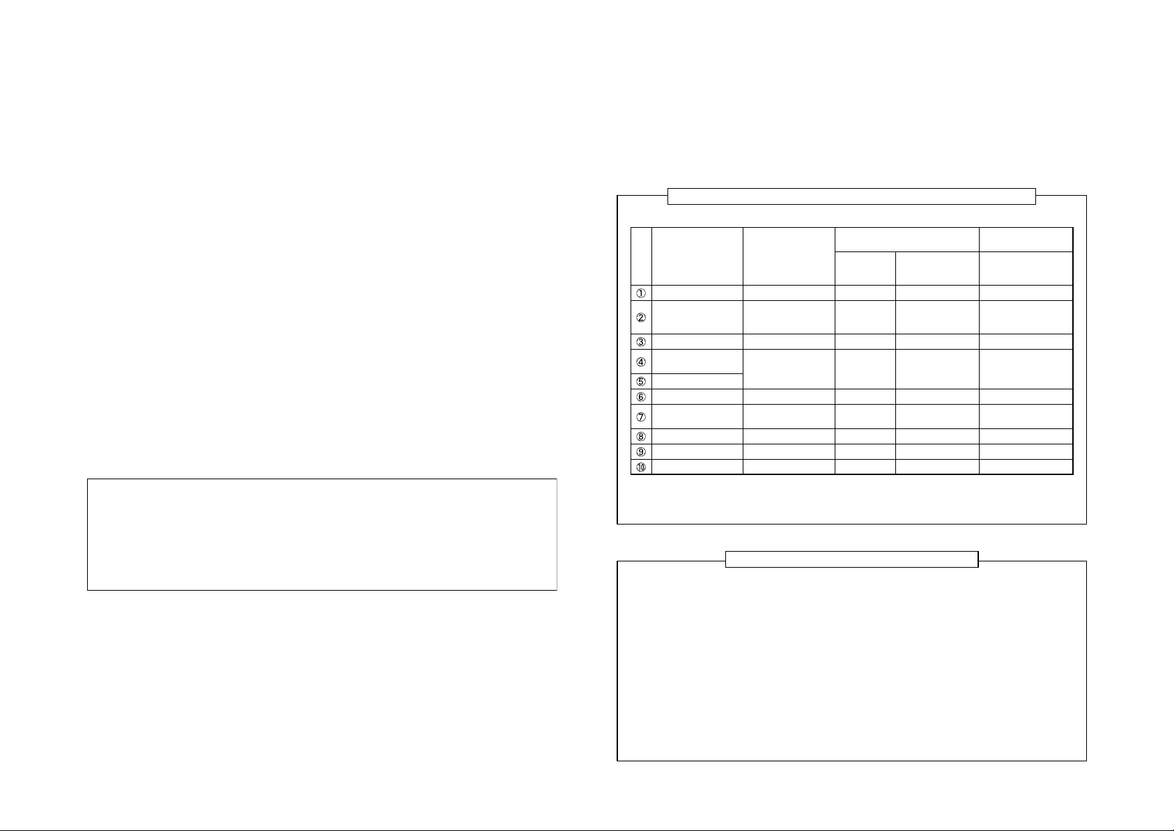
NOTE 3 :
The minimum indoor floor area compared with the
amount of refrigerant is roughly as follows:
(When the ceiling is 2.7m high)
40
Range below the
35
m²
density limit
of 0.3 kg/m³
30
(countermeasures
not needed)
25
20
15
10
5
Min. indoor floor area
0
10 20 30
Total amount of refrigerant
Range above
the density limit
of 0.3 kg/m³
(countermeasures
needed)
Indoor unit
kg
Page 3

CONTENTS
SAFETY CAUTION............................................................................................ 4
1. OUTLINE .................................................................................................... 9
2. WIRING DIAGRAM................................................................................... 13
3. PARTS RATING........................................................................................ 26
4. REFRIGERANT PIPING SYSTEMATIC DRAWING................................. 43
5. SYSTEM REFRIGERANT CYCLE DRAWING......................................... 48
6. CONTROL OUTLINE................................................................................ 55
7. APPLIED CONTROL................................................................................ 65
8. TEST OPERATION ................................................................................... 78
9. TROUBLESHOOTING............................................................................ 107
10. CONFIGURATION OF CONTROL CIRCUIT.......................................... 164
11. BACKUP OPERATIONS (EMERGENCY OPERATION) ........................ 178
12. REFRIGERANT RECOVERY
WHEN REPLACING THE COMPRESSOR ............................................ 179
13. LEAKAGE/CLOGGING OF OIL-EQUALIZATION CIRCUIT .................. 180
14. REPLACING COMPRESSOR ................................................................ 182
15. REOLACING METHOD OF PARTS ....................................................... 189
16. P.C. BOARD EXCHANGE PROCEDURES ............................................ 200
NOTE
A direct current motor is adopted for indoor fan motor in the Concealed Duct Standard Type air conditioner.
Caused from its characteristics, a current limit works on the direct current motor. When replacing the highperformance filter or when opening the service panel, be sure to stop the fan. If an above action is executed
during the fan operation, the protectiv e control works to stop the unit operation, and the check code “P12”
may be appear. However it is not a trouble. When the desired operation has finished, be sure to reset the
system to clear “P12” error code using the electric leak breaker of the indoor unit. Then push the operation
ON/OFF button of the remote controller to return to the usual operation.
Page 4
SAFETY CAUTION
The important contents concerned to the safety are described on the product itself and on this Service Man ual.
Please read this Service Manual after understanding the described items thoroughly in the following contents
(Indications/Illustrated marks), and keep them.
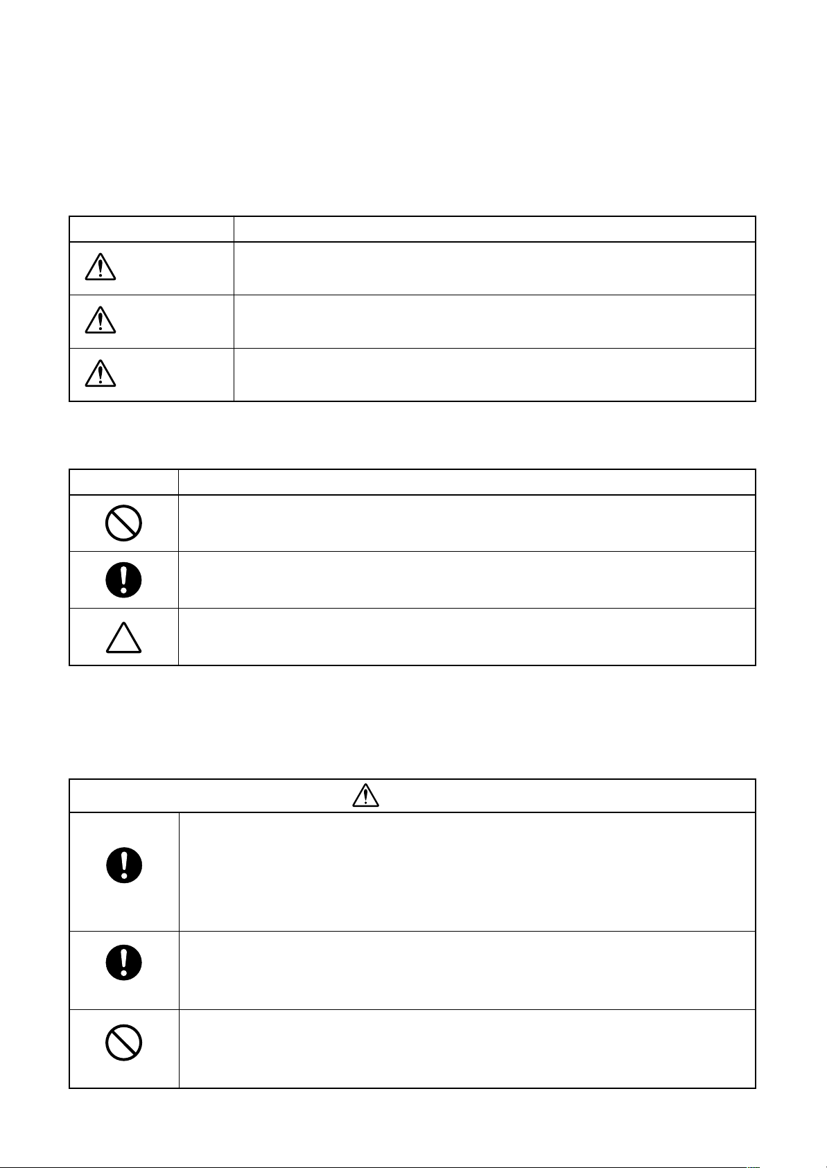
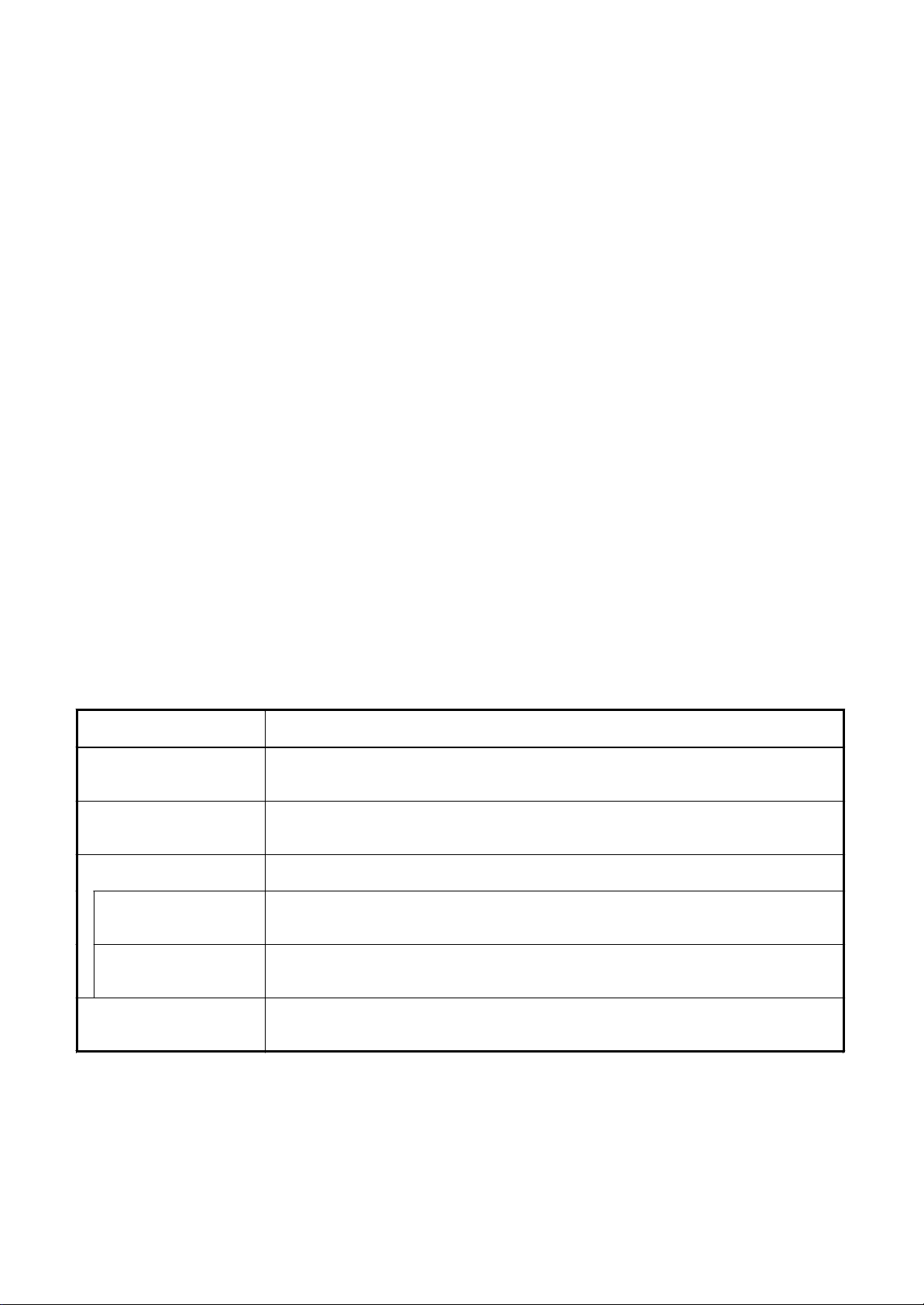
[Explanation of indications]
Indication
DANGER
WARNING
CAUTION
∗ Property damage : Enlarged damage concerned to property, furniture, and domestic animal/pet
Indicates contents assumed that an imminent danger causing a death or serious injury of
the repair engineers and the third parties when an incorrect work has been executed.
Indicates possibilities assumed that a danger causing a death or serious injury of the
repair engineers, the third parties, and the users due to troubles of the product after work
when an incorrect work has been executed.
Indicates contents assumed that an injury or property damage ( ∗) may be caused on the
repair engineers, the third parties, and the users due to troubles of the product after work
when an incorrect work has been executed.
Explanation
[Explanation of illustrated marks]
Mark Explanation
Indicates prohibited items (Forbidden items to do)
The sentences near an illustrated mark describe the concrete prohibited contents.
Indicates mandatory items (Compulsory items to do)
The sentences near an illustrated mark describe the concrete mandatory contents.
Indicates cautions (including danger/warning)
The sentences or illustration near or in an illustrated mark describe the concrete cautious contents.
[Confirmation of warning label on the main unit]
Confirm that labels are indicated on the specified positions
(Refer to the Parts disassembly diagram (Outdoor unit).)
If removing the label during parts replace, stick it as the original.
D ANGER
Turn “OFF” the breaker before removing the front panel and cabinet, otherwise an electric
shock is caused by high voltage resulted in a death or injury.
During operation, a high voltage with 400V or higher of circuit (∗) at secondary circuit of the highvoltage transformer is applied.
Turn off breaker.
Execute discharge
between terminals.
Prohibition
If touching a high voltage with the naked hands or body, an electric shock is caused even if using an
electric insulator.
∗ : For details, refer to the electric wiring diagram.
When removing the front panel or cabinet, execute short-circuit and discharge between highvoltage capacitor terminals.
If discharge is not executed, an electric shock is caused by high voltage resulted in a death or injury.
After turning off the breaker, high voltage also keeps to apply to the high-voltage capacitor.
Do not turn on the breaker under condition that the front panel and cabinet are removed.
An electric shock is caused by high voltage resulted in a death or injury.
4
Page 5
Check earth wires.
Prohibition of modification.
Use specified parts.
Do not bring a child
close to the equipment.
Insulating measures
No fire
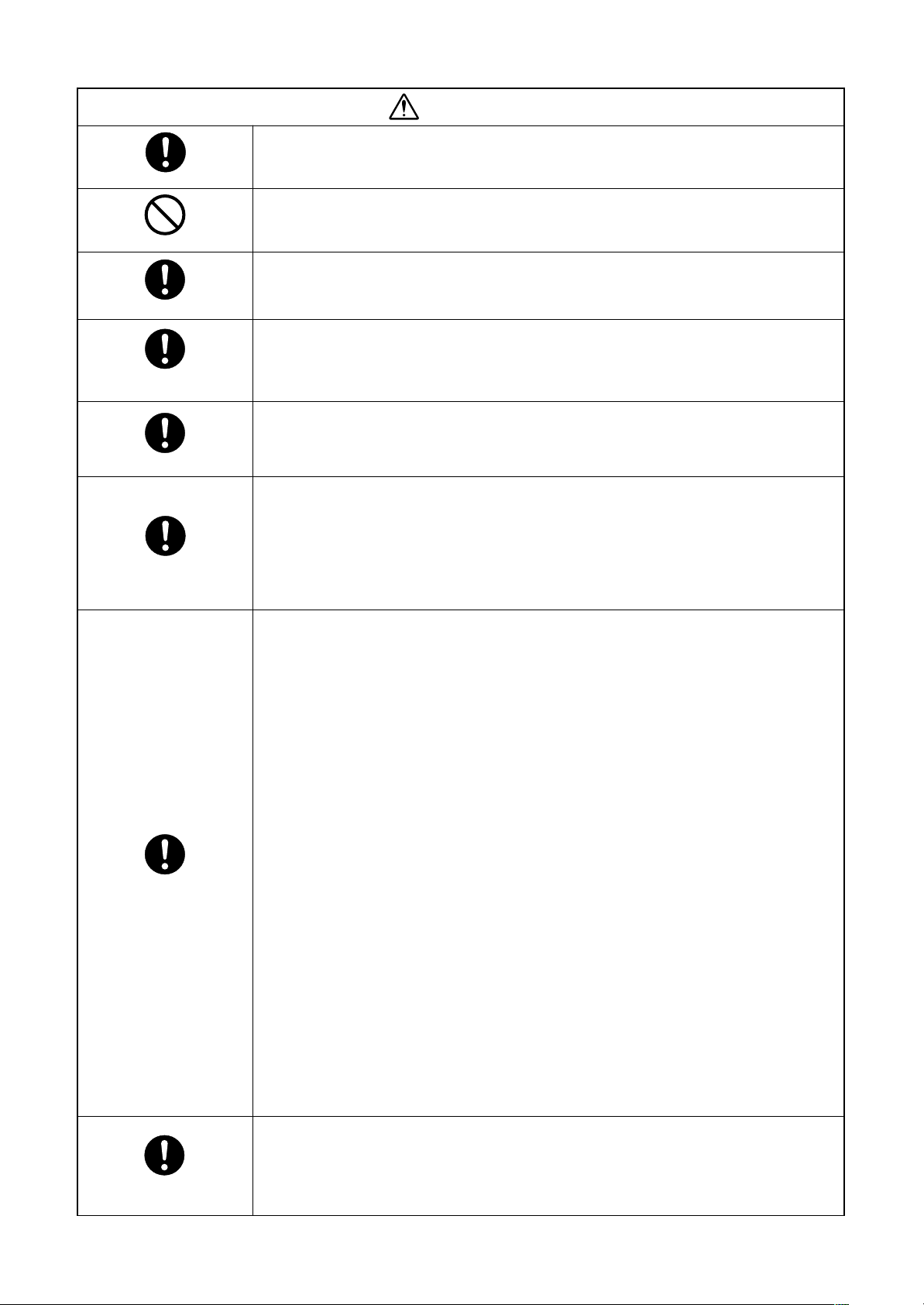
WARNING
Before troubleshooting or repair work, check the earth wire is connected to the eart h
terminals of the main unit, otherwise an electric shock is caused when a leak occurs.
If the earth wire is not correctly connected, contact an electric engineer for rework.
Do not modify the products.
Do not also disassemble or modify the parts. It may cause a fire, electric shock or injury.
For spare parts, use those specified (
If unspecified parts are used, a fire or electric shock may be caused.
∗: For details, refer to the parts list.
Before troubleshooting or repair work, do not bring a third party (a child, etc.) except
the repair engineers close to the equipment.
It causes an injury with tools or disassembled parts.
Please inform the users so that the third party (a child, etc.) does not approach the equipment.
Connect the cut-off lead cables with crimp contact, etc, put the closed end side
upward and then apply a water-cut method, otherwise a leak or production of fire is
caused at the users’ side.
When repairing the refrigerating cycle, take the following measures.
1) Be attentive to fire around the cycle. When using a gas stove, etc, be sure to put out fire
before work; otherwise the oil mixed with refrigerant gas may catch fire.
2) Do not use a welder in the closed room. When using it without ventilation, carbon
monoxide poisoning may be caused.
3) Do not bring inflammables close to the refrigerant cycle, otherwise fire of the welder may
catch the inflammables.
∗∗
∗).
∗∗
Refrigerant
Check the used refrigerant name and use tools and materials of the parts which
match with it.
For the products which use R410A refrigerant, the refrigerant name is indicated at a
position on the outdoor unit where is easy to see. To prevent miss-charging, the route of the
service por t is changed from one of the former R22.
For an air conditioner which uses R410A, never use other refrigerant than R410A.
For an air conditioner which uses other refrigerant (R22, etc.), never use R410A.
If different types of refrigerant are mixed, abnormal high pressure generates in the refrigerating cycle and an injury due to breakage may be caused.
Do not charge refrigerant additionally.
If charging refrigerant additionally when refrigerant gas leaks, the refrigerant composition in
the refrigerating cycle changes resulted in change of air conditioner characteristics or
refrigerant over the specified standard amount is charged and an abnormal high pressure is
applied to the inside of the refrigerating cycle resulted in cause of breakage or injury.
Therefore if the refrigerant gas leaks, recover the refrigerant in the air conditioner, execute
vacuuming, and then newly recharge the specified amount of liquid refrigerant. In this time,
never charge the refrigerant over the specified amount.
When recharging the refrigerant in the refrigerating cycle, do not mix the refrigerant
or air other than R410A into the specified refrigerant.
If air or others is mixed with the refrigerant, abnormal high pressure generates in the
refrigerating cycle resulted in cause of injury due to breakage.
After installation work, check the refrigerant gas does not leak.
If the refrigerant gas leaks in the room, poisonous gas generates when gas touches to fire
such as fan heater, stove or cocking stove though the refrigerant gas itself is innocuous.
Never recover the refrigerant into the outdoor unit.
When the equipment is moved or repaired, be sure to recover the refrigerant with recovering device. The refrigerant cannot be recovered in the outdoor unit; otherwise a serious
accident such as breakage or injury is caused.
Assembly/Cabling
After repair work, surely assemble the disassembled parts, and connect and lead the
removed cables as before. Perform the work so that the cabinet or panel does not
catch the inner cables.
If incorrect assembly or incorrect cable connection was done, a disaster such as a leak or
fire is caused at user’s side.
5
Page 6
WARNING
Insulator check
Ventilation
Be attentive to
electric shock
Compulsion
After the work has finished, be sure to use an insulation tester set (500V mugger) to
check the resistance is 2M
metal section (Earth position).
If the resistance value is low, a disaster such as a leak or electric shock is caused at user’s
side.
When the refrigerant gas leaks during work, execute ventilation.
If the refrigerant gas touches to a fire, poisonous gas generates. A case of leakage of the
refrigerant and the closed room full with gas is dangerous because a shortage of oxygen
occurs. Be sure to execute ventilation.
When checking the circuit inevitably under condition of the power-ON, use rubber
gloves and others not to touch to the charging section.
If touching to the charging section, an electric shock may be caused.
When the refrigerant gas leaks, find up the leaked position and repair it surely.
If the leaked position cannot be found up and the repair work is interrupted, pump-down
and tighten the service valve, otherwise the refrigerant gas may leak into the room.
The poisonous gas generates when gas touches to fire such as fan heater, stove or cocking
stove though the refrigerant gas itself is innocuous.
When installing equipment which includes a large amount of charged refrigerant such
as a multi air conditioner in a sub-room, it is necessary that the density does not the
limit even if the refrigerant leaks.
If the refrigerant leaks and exceeds the limit density, an accident of shortage of oxygen is
caused.
For the installation/moving/reinstallation work, follow to the Installation Manual.
If an incorrect installation is done, a trouble of the refrigerating cycle, water leak, electric
shock or fire is caused.
ΩΩ
Ω or more between the charge section and the non-charge
ΩΩ
Check after rerair
Check after reinstallation
Put on gloves
Cooling check
After repair work has finished, check there is no trouble.
If check is not executed, a fire, electric shock or injury may be caused. For a check, turn off
the power breaker.
After repair work (installation of front panel and cabinet) has finished, execute a test
run to check there is no generation of smoke or abnormal sound.
If check is not executed, a fire or an electric shock is caused. Before test run, install the
front panel and cabinet.
Check the following items after reinstallation.
1) The earth wire is correctly connected.
2) The power cord is not caught in the product.
3) There is no inclination or unsteadiness and the installation is stable.
If check is not executed, a fire, an electric shock or an injury is caused.
CAUTION
Be sure to put on gloves (
If not putting on gloves, an injury may be caused with the parts, etc.
(∗) Heavy gloves such as work gloves
When the power was turned on, start to work after the equipment has been
sufficiently cooled.
As temperature of the compressor pipes and others became high due to cooling/heating
operation, a burn may be caused.
∗∗
∗) during repair work.
∗∗
6
Page 7
• New Refrigerant (R410A)
4. Tools
(1) Required Tools for R410A
Mixing of different types of oil may cause a troub le such as generation of sludge, clogging of capillary, etc.
Accordingly, the tools to be used are classified into the following three types.
1) Tools exclusive for R410A (Those which cannot be used for conventional refrigerant (R22))
2) Tools exclusive for R410A, but can be also used for conventional refrigerant (R22)
3) Tools commonly used for R410A and for conventional refrigerant (R22)
The table below shows the tools exclusive for R410A and their interchangeability.
Tools exclusive for R410A (The following tools for R410A are required.)
Tools whose specifications are changed for R410A and their interchangeability
No. Used tool
Flare tool
Copper pipe gauge for
adjusting projection
margin
Torque wrench
Gauge manifold
Charge hose
Vacuum pump adapter
Electronic balance for
refrigerant charging
Refrigerant cylinder
Leakage detector
Charging cylinder
Usage
Pipe flaring
Flaring by conventional
flare tool
Connection of flare nut
Evacuating, refrigerant
charge, run check, etc.
Vacuum evacuating
Refrigerant charge
Refrigerant charge
Gas leakage check
Refrigerant charge
Conventional air
conditioner installation
Whether new equipment
can be used with
conventional refrigerant
Yes
*(Note 1)
No
No
Yes
Yes
No
Yes
No
Whether conventional equipment can
be used
*(Note 1)
*(Note 1)
No
No
No
Yes
No
No
No
(1) Vacuum pump
Use vacuum pump by
attaching vacuum pump adapter.
(2) Torque wrench
(3) Pipe cutter
(4) Reamer
(5) Pipe bender
(6) Level vial
(7) Screwdriver (+, –)
(8) Spanner or Monkey wrench
(9) Hole core drill
(10) Hexagon wrench (Opposite side 4mm)
(11) Tape measure
(12) Metal saw
Also prepare the following equipments f or other installation method and run check.
(1) Clamp meter
(2) Thermometer
(3) IInsulation resistance tester
(4) Electroscope
Existence of
new equipment
for R410A
Yes
Yes
Yes
Yes
Yes
Yes
Yes
Yes
(Note 2)
R410A
air conditioner installation
(Note 1) When flaring is carried out for R410A using the conventional flare tools , adjustment of projection
margin is necessary. For this adjustment, a copper pipe gauge, etc. are necessary .
(Note 2) Charging cylinder for R410A is being currently developed.
General tools (Conventional tools can be used.)
In addition to the above exclusive tools, the following equipments which serve also for R22 are necessary
as the general tools.
This air conditioner adopts a new HFC type refrigerant (R410A) which does not deplete the ozone lay er.
1. Safety Caution Concerned to New Refrigerant
7
The pressure of R410A is high 1.6 times of that of the former refrigerant (R22). Accompanied with change of
refrigerant, the refrigerating oil has been also changed. Therefore, be sure that water, dust, the f ormer refrigerant or the former refrigerating oil is not mixed into the refrigerating cycle of the air conditioner with new refrigerant during installation work or service work. If an incorrect work or incorrect service is performed, there is a
possibility to cause a serious accident. Use the tools and materials exclusiv e to R410A to purpose a safe work.
2. Cautions on Installation/Service
(1) Do not mix the other refrigerant or refrigerating oil.
For the tools exclusive to R410A, shapes of all the joints including the service port differ from those of the
former refrigerant in order to prevent mixture of them.
(2) As the use pressure of the new refrigerant is high, use material thickness of the pipe and tools which are
specified for R410A.
(3) In the installation time, use clean pipe materials and work with great attention so that water and others do
not mix in because pipes are affected by impurities such as water, oxide scales, oil, etc. Use the clean
pipes.
Be sure to brazing with flowing nitrogen gas. (Never use gas other than nitrogen gas.)
(4) For the earth protection, use a vacuum pump for air purge.
(5) R410A refrigerant is azeotropic mixture type refrigerant. Therefore use liquid type to charge the refrigerant.
(If using gas for charging, composition of the refrigerant changes and then characteristics of the air condi-
tioner change.)
3. Pipe Materials
For the refrigerant pipes, copper pipe and joints are mainly used. It is necessary to select the most appropriate
pipes to conform to the standard. Use clean material in which impurities adhere inside of pipe or joint to a
minimum.
(1) Copper pipe
<Piping>
The pipe thickness, flare finishing size, flare nut and others differ according to a refrigerant type .
When using a long copper pipe for R410A, it is recommended to select “Copper or copper-base pipe without
seam” and one with bonded oil amount 40mg/10m or less. Also do not use crushed, deformed, discolored
(especially inside) pipes. (Impurities cause clogging of expansion valves and capillary tubes.)
<Flare nut>
Use the flare nuts which are attached to the air conditioner unit.
(2) Joint
The flare joint and socket joint are used for joints of the copper pipe. The joints are rarely used for installa-
tion of the air conditioner. However clear impurities when using them.
Page 8
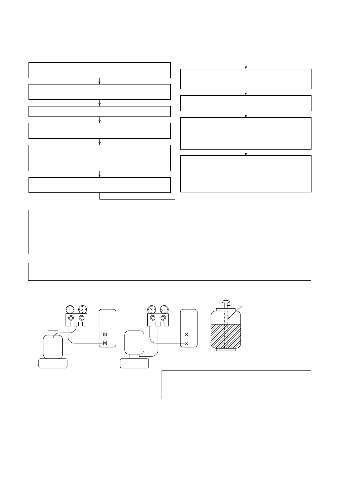
5. Recharge of Refrigerant
When recharge of the refrigerant is required, charge the new refrigerant with the specified amount in the
procedure as described below .
Recover the refrigerant and check there is no refrigerant in the
equipment.
Connect the charge hose to the packed valve service ports at gas
side, liquid side, and balance side of the outdoor unit.
Connect the charge hose to vacuum pump adaptor.
Open the packed valves of the balance pipe fully at liquid and gas
sides, and then return the valve at gas side a little to the closed side.
Open fully PMV of the outdoor unit.
• Turn on power of the outdoor unit.
• Short CN30 on I/F P.C. board of the outdoor unit.
Turn off power of the outdoor unit within 2 minutes after short-circuiting.
•
Open fully the handle Low of the gauge manifold, and then turn on
the power of vacuum pump for vacuuming.
When the pressure has lowered until indication of the
compound gauge pointed -0.1MPa (-76cmHg), open fully the
handle Low and turn off the power of vacuum pump.
Leave it as it is for 1 to 2 minutes and check the indicator of
the compound gauge does not return.
Set the refrigerant cylinder on the electron balance, connect
the charging hose to connecting ports of the cylinder and the
electron gauge, and then charge the liquid refrigerant from the
service port at liquid side. (Shield with the gauge manifold so
that refrigerant does not flow to gas side.)
When the specified amount of refrigerant cannot be charged,
charge the liquid refrigerant into the service port at suction
gas side while carrying out the all cooling operation.
In this time, reduce slightly amount of refrigerant with valve of
the cylinder for charging. The liquid refrigerant may be rapidly
charged, so charge the refrigerant carefully and slowly.
Never charge the refrigerant ov er the specified amount.
Q
Do not charge the additional refrigerant.
R
If charging refrigerant additionally when refrigerant gas leaks, the refrigerant composition in the refrigerating cycle
changes resulted in change of air conditioner characteristics or refrigerant over the specified standard amount is
charged and an abnormal high pressure is applied to the inside of the refrigerating cycle resulted in cause of breakage
or injury.
Set the equipment so that liquid refrigerant can be charged.
Q
When using a cylinder with siphon pipe, liquid can be charged without inversing the cylinder.
R
[ Cylinder with siphon ] [ Cylinder without siphon ]
Refrigerant
cylinder
Electronic
balance
Gauge manifold
OUTDOOR unit
Electronic
balance
Gauge manifold
cylinder
Refrigerant
OUTDOOR unit
Siphon
R410A refrigerant is consisted with HFC mixed refrigerant.
Therefore if the refrigerant gas is charged, the composition
of the charged refrigerant changes and characteristics of
the equipment changes.
6. Environment
Use “Vacuum pump method” for an air purge (Discharge of air in the connecting pipe) in installation time.
• Do not discharge flon gas into the air to protect the earth environment.
• Using the vacuum pump method, clear the remained air (Nitrogen, etc.) in the unit. If the air remains , the
pressure in the refrigerating cycle becomes abnormally high and an injury and others are caused due to burst.
8
Page 9
1. OUTLINE
“Super Heat Recovery Multi System” is a multi air conditioning system which enables each
indoor unit in a refrigerant line to independently select cooling or heating operation.
As it is available to operate simultaneously in cooling and heating modes, more amount of
heat recovery becomes possible. This system is the most appropriate one for a building or
etc. where cool and heat air are mixed such as a building of which temperature difference
between each room is large due to influence of daylight or a building which has a server room
requiring for cool air all day.
Heating and cooling operation are automatically selected in individual unit;
You can save time for operation.
For example, when heating is required for early morning and cooling for daytime, a Flow Selector Unit provides
automatically a smooth selection of heating or cooling operation. Therefore you can obtain a comfortable
room environment without feeling somewhat out of place and moreover you can save time to select heat/
cool operation.
INFORMATION
The Super Heat Recovery Multi system is different from the conventional Multi air conditioner in several points
such as that heating and cooling operations are mixed or only a part of the air conditioner works cooling function. For this reason, the fo llowing table explains the operation modes of this air conditioner.
The following table explains representation of the operation modes in this Manual.
<Operation mode>
Operation mode Outline
1. All Cooling All indoor units are under cooling operation only without heating operation.
Outdoor heat exchanger (Main heat exchanger) is used as condenser .
2. All Heating All indoor units are under heating operation only without cooling operation.
Outdoor heat exchanger (Main heat exchanger) is used as ev apor ator.
3. Simultaneous operation MIU for simultaneous operation
3-1. Mainly cooling, partly
heating operation
3-2. Mainly heating, partly
cooling operation
Indoor units are under heating/cooling simultaneous operation with subjective cooling operation
Outdoor heat exchanger (Sub heat exchanger) is used as condenser.
Indoor units are under heating/cooling simultaneous operation with subjective heating operation
Outdoor heat exchanger (Main heat exchanger) is used as ev apor ator.
4. Defrost Using reversing operation of 4-way valve , ice of the outdoor heat exchanger is dissolv ed w ith
single cooling cycle.
9
Page 10
1-1. Components Lineup in Super Heat Recovery Multi Using
High-efficiency Refrigerant R410A
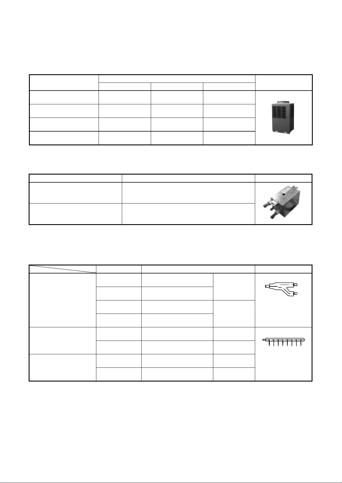
1. Outdoor units
Corresponding HP
Model name
Cooling capacity (kW) 22.4 28.0 33.5
Heating capacity (kW) 25.0 31.5 35.5
Number of connectable
indoor units
MMY- MAP0801FT8 MAP1001FT8 MAP1201FT8
8HP 10HP 12HP
13.0 16.0 16.0
Inverter unit
2. Flow selector units (FS unit)
Model name Usage Appearance
RBM-Y1121FE Capacity rank for indoor unit : Type 007 to 030
RBM-Y1801FE Capacity rank for indoor unit : Type 036 to 056
* Accessory part (Sold separately): Connection cable kit (RBC-CBK15FE), up to 15m.
Appearance
3. Branching joints and headers
Model name Usage Appearance
RBM-BY53FE
RBM-BY103FE
Y-shape branching joint (∗3)
RBM-BY53E
RBM-BY103E
RBM-HY1043FE
4-branching header (∗4)
RBM-HY1043E
RBM-HY1083FE
8-branching header (∗4)
RBM-HY1083E
∗1 “Capacity code” can be obtained from page 11. (Capacity code is not actual capacity)
∗2 If total capacity code value of indoor unit exceeds that of outdoor unit, apply capacity code of outdoor unit.
∗3 When using Y-shape branching joint for 1st branching, select according to capacity code of outdoor unit.
∗4 Max. 6.0 capacity code in total can be connected.
∗5 This is used for branching to “cooling only” indoor unit.
∗6 Model names for outdoor described in this guide are shortened because of the space constraint.
Indoor unit capacity code (∗1)
Total below 6.4
Indoor unit capacity code (∗1)
Total below 14.2
Indoor unit capacity code (∗1)
Total below 6.4
Indoor unit capacity code (∗1)
Total below 14.2
Indoor unit capacity code (
Total below 14.2
Indoor unit capacity code (∗1)
Total below 14.2
Indoor unit capacity code (∗1)
Total below 14.2
Indoor unit capacity code (
Total below 14.2
∗
∗
For 3 piping
For 2 piping (
1)
For 3 piping
For 2 piping (
For 3 piping
1)
For 2 piping (∗5)
5)
∗
5)
∗
10
Page 11
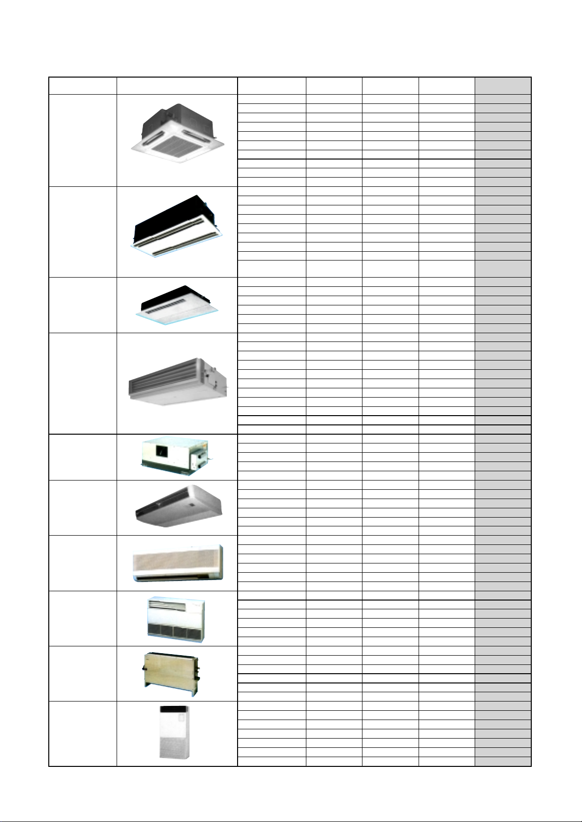
4. Indoor units
Type Appearance Model name Capacity rank Capacity code
009 type 1 2.8
012 type 1.25 3.6
015 type 1.7 4.5
018 type 2 5.6
024 type 2.5 7.1
027 type 3 8.0
030 type 3.2 9.0
036 type 4 11.2
048 type 5 14.0
056 type 6 16.0
007 type 0.8 2.2
009 type 1 2.8
012 type 1.25 3.6
015 type 1.7 4.5
018 type 2 5.6
024 type 2.5 7.1
027 type 3 8.0
030 type 3.2 9.0
048 type 5 14.0
007 type 0.8 2.2
009 type 1 2.8
012 type 1.25 3.6
015 type 1.7 4.5
018 type 2 5.6
024 type 2.5 7.1
007 type 0.8 2.2
009 type 1 2.8
012 type 1.25 3.6
015 type 1.7 4.5
018 type 2 5.6
024 type 2.5 7.1
027 type 3 8.0
030 type 3.2 9.0
036 type 4 11.2
048 type 5 14.0
056 type 6 16.0
018 type 2 5.6
024 type 2.5 7.1
027 type 3 8.0
036 type 4 11.2
048 type 5 14.0
015 type 1.7 4.5
018 type 2 5.6
024 type 2.5 7.1
027 type 3 8.0
036 type 4 11.2
048 type 5 14.0
007 type 0.8 2.2
009 type 1 2.8
012 type 1.25 3.6
015 type 1.7 4.5
018 type 2 5.6
024 type 2.5 7.1
007 type 0.8 2.2
009 type 1 2.8
012 type 1.25 3.6
015 type 1.7 4.5
018 type 2 5.6
024 type 2.5 7.1
007 type 0.8 2.2
009 type 1 2.8
012 type 1.25 3.6
015 type 1.7 4.5
018 type 2 5.6
024 type 2.5 7.1
015 type 1.7 4.5
018 type 2 5.6
024 type 2.5 7.1
027 type 3 8.0
036 type 4 11.2
048 type 5 14.0
056 type 6 16.0
4-way Air Discharge
Cassette Type
2-way Air Discharge
Cassette Type
1-way Air Discharge
Cassette Type
Concealed Duct
Standard Type
Concealed Duct
High Static
Pressure Type
Under Ceiling Type
High Wall Type
Floor Standing
Cabinet Type
Floor Standing
Concealed Type
Floor Standing Ty pe
MMU-AP0091H
MMU-AP0121H
MMU-AP0151H,
MMU-AP0181H
MMU-AP0241H
MMU-AP0271H
MMU-AP0301H
MMU-AP0361H
MMU-AP0481H
MMU-AP0561H
MMU-AP0071WH
MMU-AP0091WH
MMU-AP0121WH
MMU-AP0151WH
MMU-AP0181WH
MMU-AP0241WH
MMU-AP0271WH
MMU-AP0301WH
MMU-AP0481WH
(CHINA only)
MMU-AP0071YH
MMU-AP0091YH
MMU-AP0121YH
MMU-AP0151SH
MMU-AP0181SH
MMU-AP0241SH
MMD-AP0071BH
MMD-AP0091BH
MMD-AP0121BH
MMD-AP0151BH
MMD-AP0181BH
MMD-AP0241BH
MMD-AP0271BH
MMD-AP0301BH
MMD-AP0361BH
MMD-AP0481BH
MMD-AP0561BH
MMD-AP0181H
MMD-AP0241H
MMD-AP0271H
MMD-AP0361H
MMD-AP0481H
MMC-AP0151H
MMC-AP0181H
MMC-AP0241H
MMC-AP0271H
MMC-AP0361H
MMC-AP0481H
MMK-AP0071H
MMK-AP0091H
MMK-AP0121H
MMK-AP0151H
MMK-AP0181H
MMK-AP0241H
MML-AP0071H
MML-AP0091H
MML-AP0121H
MML-AP0151H
MML-AP0181H
MML-AP0241H
MML-AP0071BH
MML-AP0091BH
MML-AP0121BH
MML-AP0151BH
MML-AP0181BH
MML-AP0241BH
MMF-AP0151H
MMF-AP0181H
MMF-AP0241H
MMF-AP0271H
MMF-AP0361H
MMF-AP0481H
MMF-AP0561H
Cooling
capacity (kW)
Heating
capacity (kW)
3.2
4.0
5.0
6.3
8.0
9.0
10.0
12.5
16.0
18.0
2.5
3.2
4.0
5.0
6.3
8.0
9.0
10.0
16.0
2.5
3.2
4.0
5.0
6.3
8.0
2.5
3.2
4.0
5.0
6.3
8.0
9.0
10.0
12.5
16.0
18.0
6.3
8.0
9.0
12.5
16.0
5.0
6.3
8.0
9.0
12.5
16.0
2.5
3.2
4.0
5.0
6.3
8.0
2.5
3.2
4.0
5.0
6.3
8.0
2.5
3.2
4.0
5.0
6.3
8.0
5.0
6.3
8.0
9.0
12.5
16.0
18.0
11
Page 12
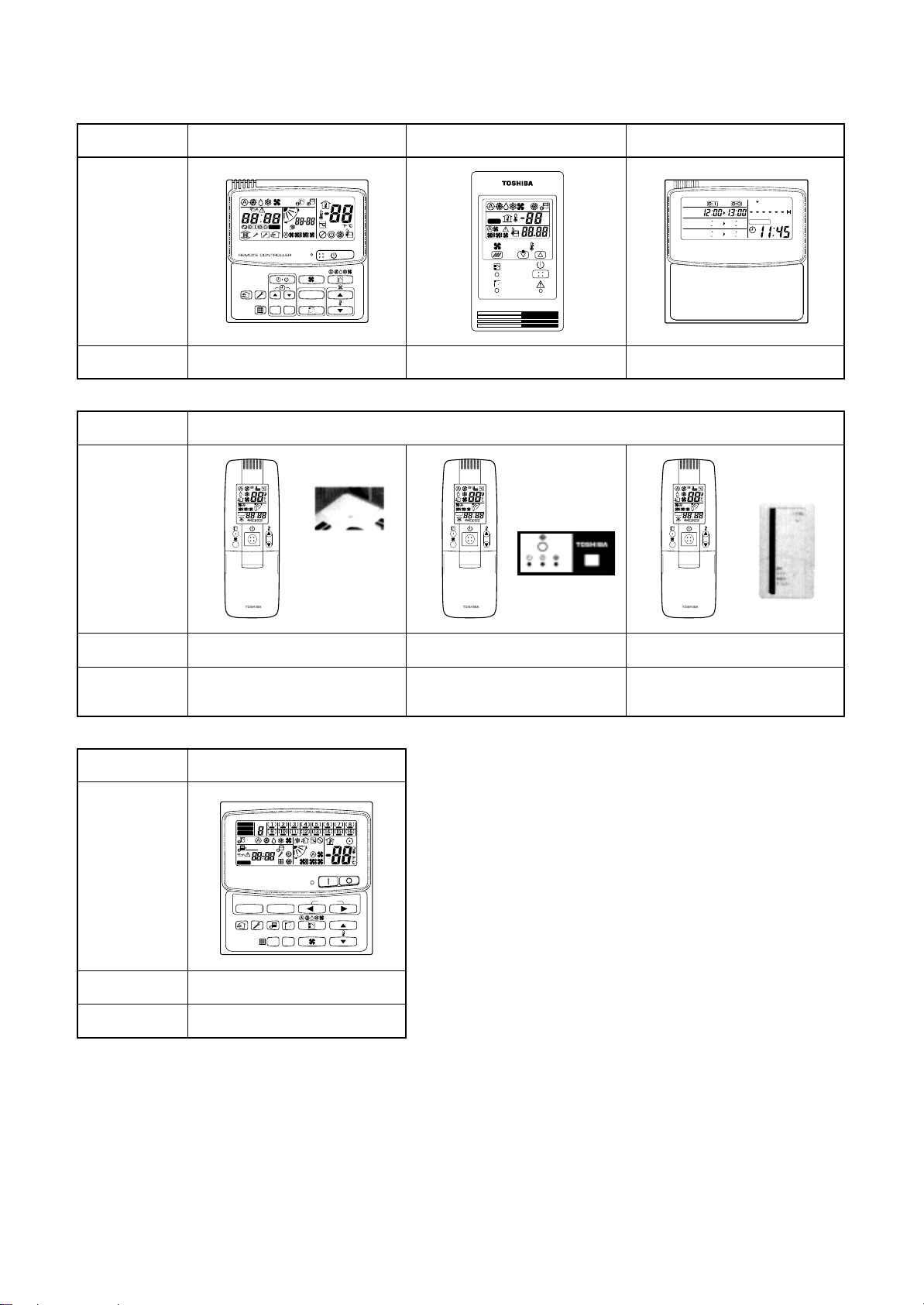
n Remote controller switch
˚C
˚F
TEST
SETTING
Name
Appearance
Model name
Appearance
Wired remote controller
UNIT No.
R.C. No.
CODE No.
UNIT
SET DATA
SETTING
TEST
CL
SET
RBC-AMT21E
Simple wired remote controller
RBC-AS21E
Wireless remote controller kitName
Receiver section
ADR ADR ADR
Receiver section
Weekly timer
PROGRAM1
PROGRAM2
PROGRAM3
WEEKLY TIMER
SuMoTuWeThFr Sa
ERROR
RBC-EXW21E
Receiver section
laid separately
Model name
Type
Name
Appearance
Model name
Type
RBC-AX2U (W)-E
4-way Air Discharge
Cassette type
Central remote controller
ZONE
ALL
ZONE
GROUP
1234
UNIT No.
SET DATA
SETTING
No.
R.C.
SELECT ZONE
CL
TEST
SET
GROUP
CODE
No.
TCB-SC642TLE
64 system center controller
RBC-AX22CE
Under Ceiling type
TCB-AX21E
Separate sensor type
12
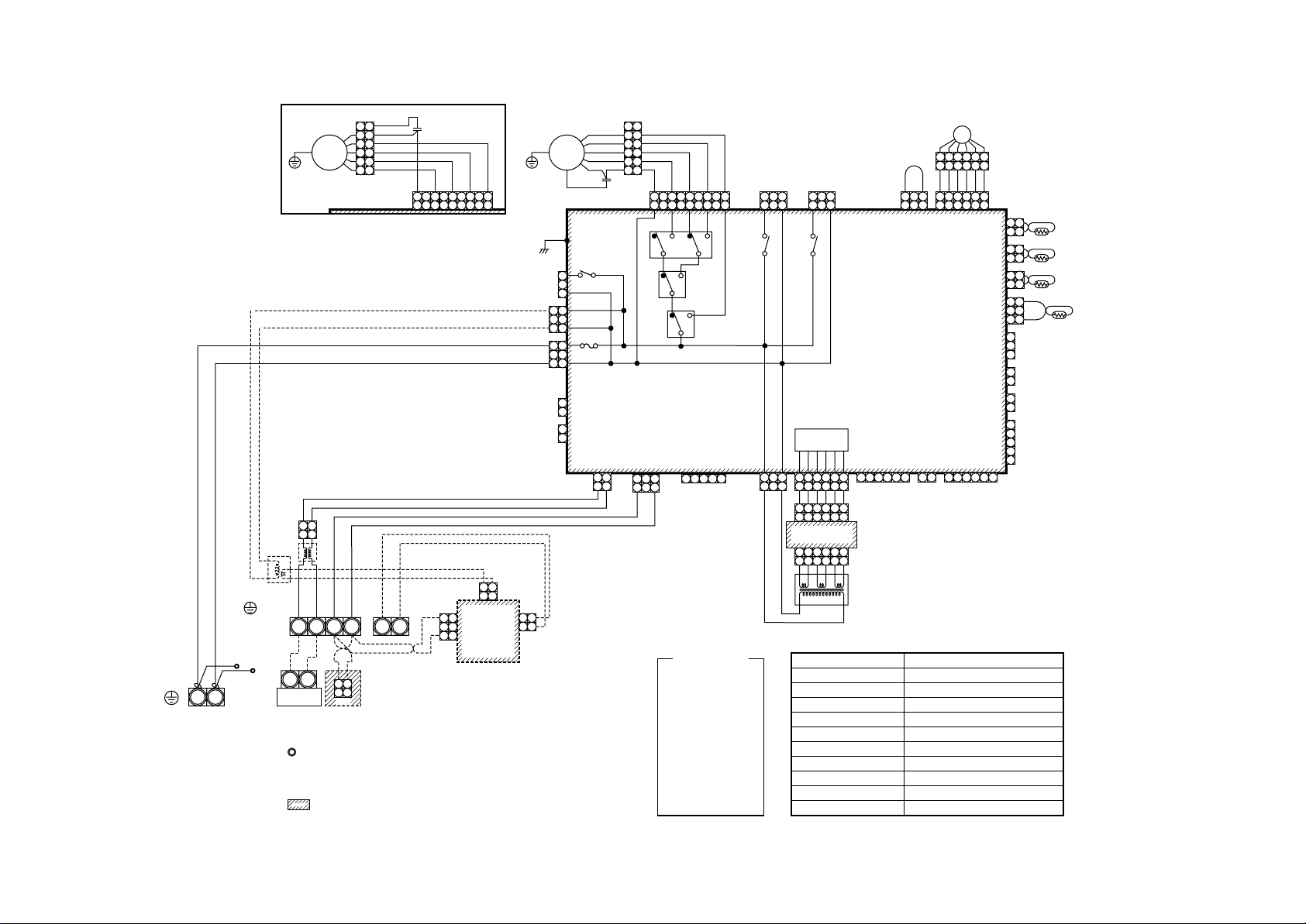
Page 13
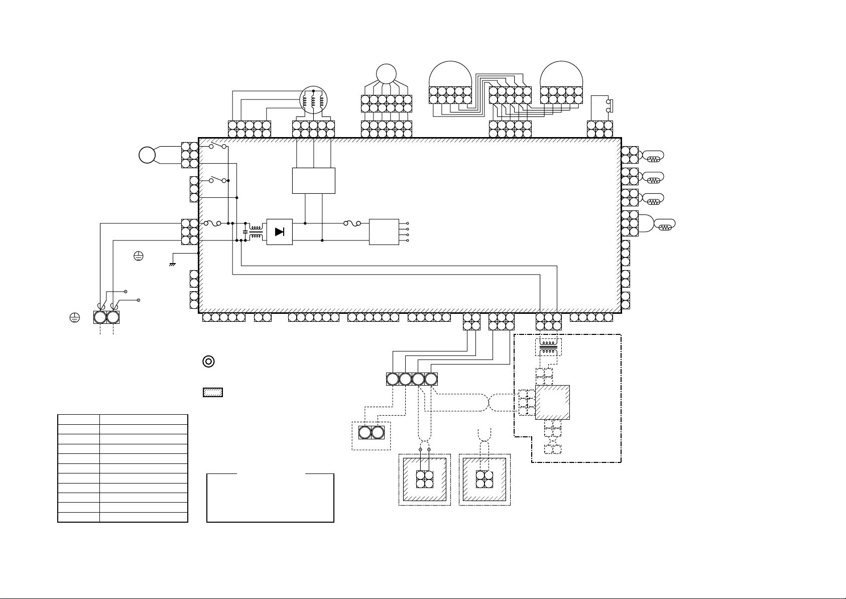
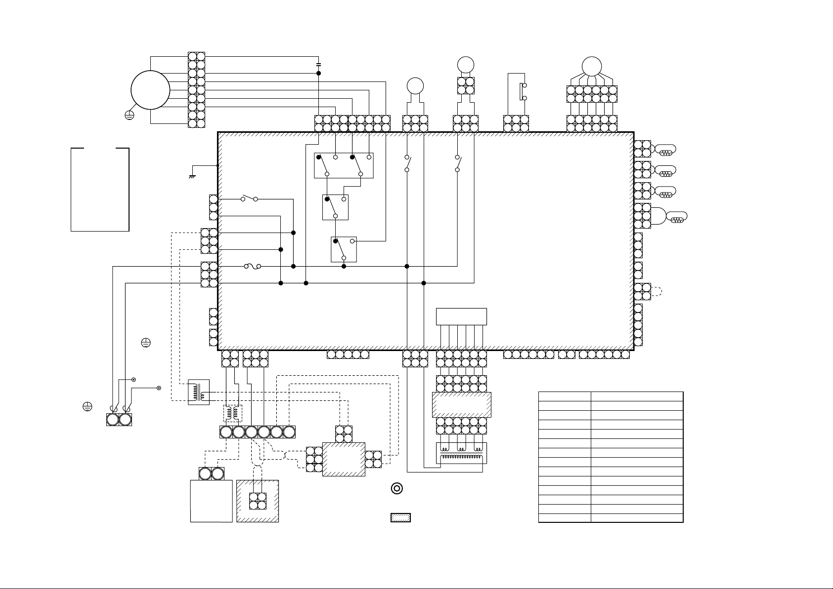
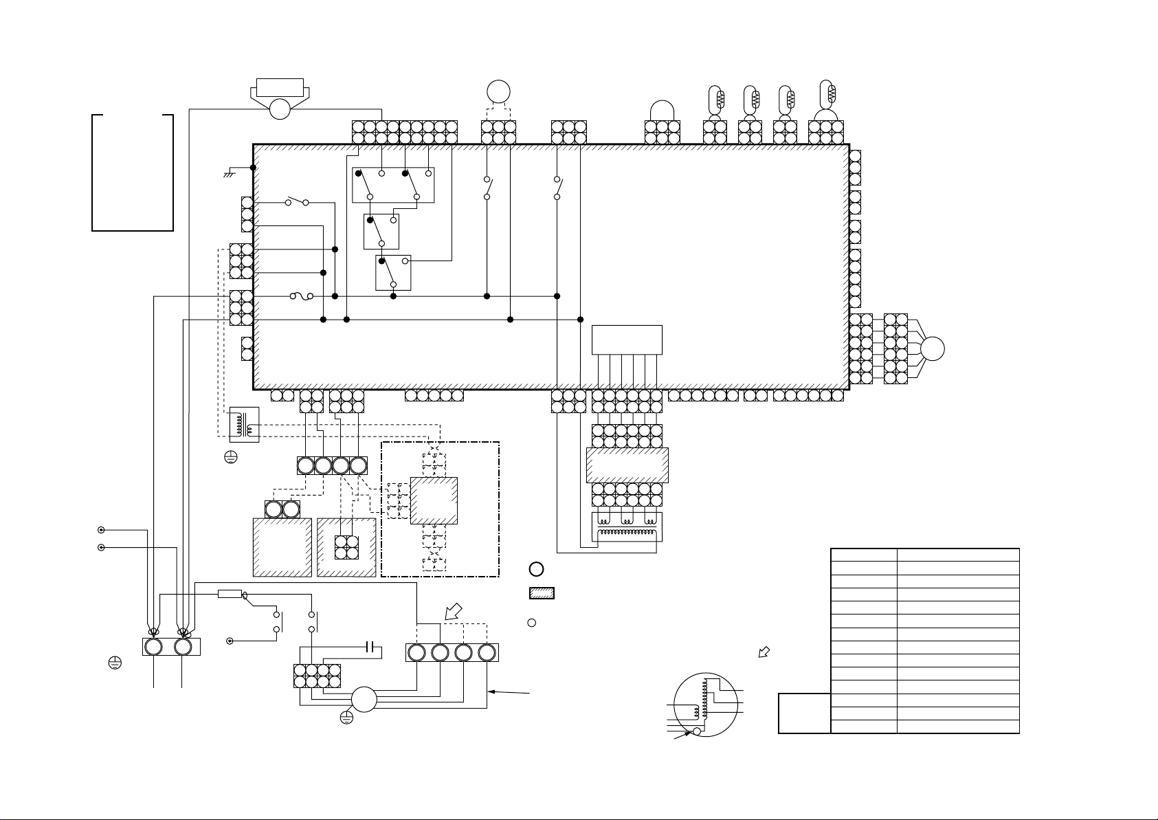
2. WIRING DIA GRAM
2-1. Indoor Unit
2-1-1. 4-way Air Discharge Cassette Type
Model: MMU-AP0091H, AP0121H, AP0151H, AP0181H, AP0241H,
13
Indoor unit
Earth screw
Symbol
FM
TA
TC1
TCJ
TC2
LM1, LM2
DM
FS
RY302
PMV
Flow selector
S(N)R(L)
Power supply
Single phase
220-240V 50Hz
220V 60Hz
Fan motor
Indoor temp sensor
Temp sensor
Temp sensor
Temp sensor
Lover motor
Drain pump motor
Float switch
Drain control relay
Pulse Motor Valve
DM
unit earth
screw
RED
WHI
Closed end
connector
Parts name
~
~
CN32
(WHI)
1 2
(Fandrive)
CN334
(BLU)
T10
RY302
RY303
Fuse
T6.3A
250V~
P301
5 4 3 2 1
5 4 3 2 1
CN50
(WHI)
CN304
(GRY)
RED
CN67
(BLK)
WHI
CN66
(WHI)
CN44
(BLN)
CN68
(BLU)
1
2
3
1
2
3
BLK
1
2
3
1
2
3
1
2
3
1
2
1
2
4 5 6
1. indicates the terminal block, letter at inside
indicates the terminal number.
2. A dotted line and broken line indicate the wiring at site.
3. indicates the control P.C. board.
Color identification
RED : RED
WHI : WHITE
YEL : YELLOW
BLU : BLUE
BRN : BROWN
BLK : BLACK
GRY : GRAY
PNK : PINK
ORN : ORANGE
GRN : GREEN
PMV
FM
6 4 3 1 2 5
6 4 3 1 2 5
CN333
1 2 3 4 5
1 2 3 4 5 6
Motor drive
circuit
+
–
CN61
(YEL)
1 2 3 4 51 2 3
(WHI)
Fuse
T3.15A
250V~
1 2 3 4 5 6
1 2 3 4 5
CN60
(WHI)
1 2
3 4 5 6
(Option)
Power
supply
circuit
U2U1
Outdoor unit
U2
U1
LM2
1 2 3 4 5
1 2 3 4 5
CN82
(BLU)
Indoor control P.C. board
MCC-1402
DC20V
DC15V
DC12V
DC7V
CN81
(BLK)
1 2 3 4 5
CN40
(BLU)
1 2
1 2
BLU
BA
WHI
BLK WHI BLK
CN1
(WHI)
1 2
1 2
Wired remote
controller
Adaptor for wireless
remote controller
BLU
1 2
1 2
1 2 3 4 5
1 2 3 4 5
1 2 3 4 5
1 2 3 4 5
CN41
(BLU)
1 2 3
1 2 3
BLK
BLK
BLK
WHI
CN001
(WHI)
CN309
(YEL)
CN01
(WHI)
3 3
2 2
1 1
CN02
(BLU)
LM1
1 2 3 4 5
1 2 3 4 5
CN33
(WHI)
1 2 3
1 2 3
1 2
Network adaptor
(Option)
1 2
Network
adaptor
P.C. board
1 2
1 2
X Y
CN20
(BLU)
1 2 3 4 5
TR
MCC-1401
CN03
(RED)
3 1
321
CN104
(YEL)
CN102
(RED)
CN101
(BLK)
CN100
(BRN)
CN80
(GRN)
CN73
(RED)
CN70
(WHI)
FS
CN34
(RED)
121
2
121
2
121
2
121
2
33
1
PNL
2
3
1
EXCT
2
1
Filter input
2
MMU-AP0271H, AP0301H, AP0361H, AP0481H, AP0561H
TA
TCJ
TC2
TC1
Page 14
14
Color
indication
RED : RED
WHI : WHITE
YEL : YELLOW
BLU : BLUE
BLK : BLACK
GRY : GRAY
PNK : PINK
ORN : ORANGE
BRW : BROWN
GRN : GREEN
Indoor unit
Earth screw
220-240V 50Hz
220V 60Hz
Flow selector
S(N)R(L)
Power supply
Single phase
FM
unit earth
screw
Closed end
connector
CN039
(YEL)
WHI
121
2
RED
343
4
565
6
77
9
(BLK)
CN304
(GRY)
1
2
3
1
2
3
CN066
(WHI)
CN044
(BRW)
TR
Line Filter
1
Outdoor unit
1
2
3
1
2
3
1
2
3
1
2
1
2
U2U
P301
CN067
(BLK)
CN040
(BLU)
1 2
1 2
BLU
BLU
U
1
U
RY004
Fuse
T5.0A
250V~
CN041
(BLU)
1 2 3
1 2 3
BLK
BLK
BA
2
CN1
(WHI)
1 2
1 2
Remote controller
FAN
CN083
YX
(WHI)
RED
RY007
3 3
1 1
CN02
(BLU)
RC
BLK
9 8 7 6
9 8 7 6
ORN
5 4 3 2 1
5 4 3 2 1
HML UL
RY006
RY005
CN050
(WHI)
1 2 3 4 5
Network
1 2
1 2
adaptor
(Option)
CN01
(WHI)
2
MCC-1401
LM
BLU
YEL
RY002
DM
1 2 3
1 2 3
CN068
DP
(BLU)
RY001
1 2
1 2
1 2 3
1 2 3
LM
(GRN)
CN033
Indoor control P.C. board
Power supply
circuit
4 5 6
CN075
(WHI)
CN02
(YEL)
CN01
(WHI)
TR
CN074
(WHI)
1 2 3
1 2 3
1 2 3
1 2 3 4 5 6
1 2 3 4 5 6
Sub P.C. board
MCC-1520
1 2 3 4 5 6
1 2 3 4 5 6
1 1
2 2
CN03
(RED)
1. indicates the terminal block, letter at inside
indicates the terminal number.
2. A dotted line and broken line indicate the wiring at site.
3. indicates the control P.C. board.
1 2 3
1 2 3
1 2 3 4 5 61 2 3 4 5 6
FS
CN061
(YEL)
FS
(RED)
CN030
6 4 3
6 4 3
1 2 3
1 2 3
CN032
(WHI)
1 2
Fan drive
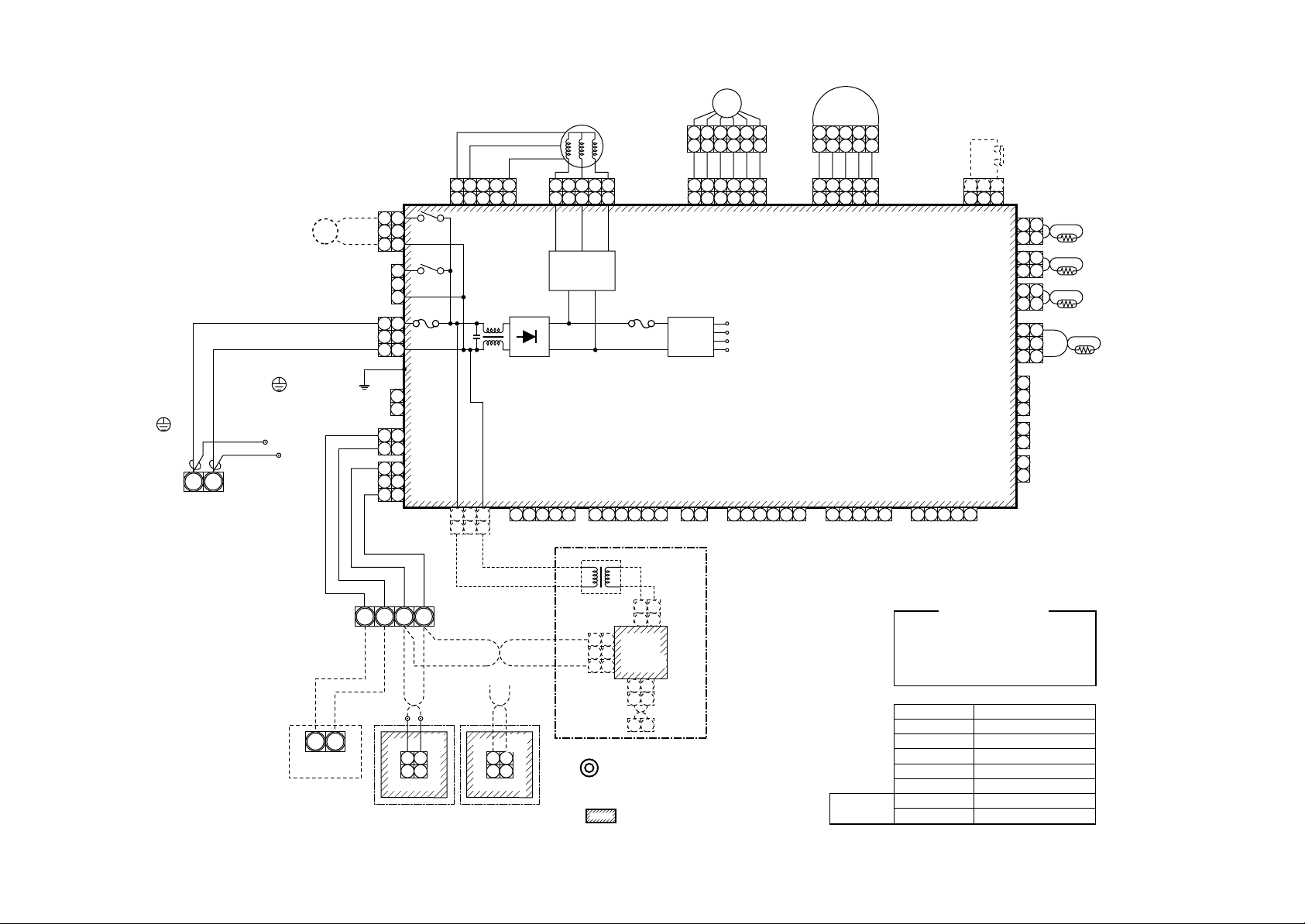
Symbol
FM
RC
TR
LM
TA
TC1,TC2,TCJ
RY001
RY002
RY004
RY005~007
FS
DM
PMV
PMV
1 2 5
1 2 5
PMV
4 5 6
(BLU)
4 5 6
CN082
CN104
(YEL)
CN102
(RED)
CN101
(BLK)
CN100
(BRW)
CN080
(GRN)
CN073
(RED)
CN070
(WHI)
CN081
(BLK)
CN060
(WHI)
1 2 3 4 5 6
Option
Parts name
Fan motor
Running capacitor
Transformer
Louver motor
Indoor temp sensor
Temp sensor
Louver control relay
Drain control relay
Heater control relay
Fan motor control relay
Float switch
Drain pump motor
Pulse Motor Valve
2
2
2
2
1
2
3
1
2
1
2
1
2
3
4
5
121
121
121
121
33
PNL
EXCT
1
2
TA
TCJ
TC2
Filter
TC1
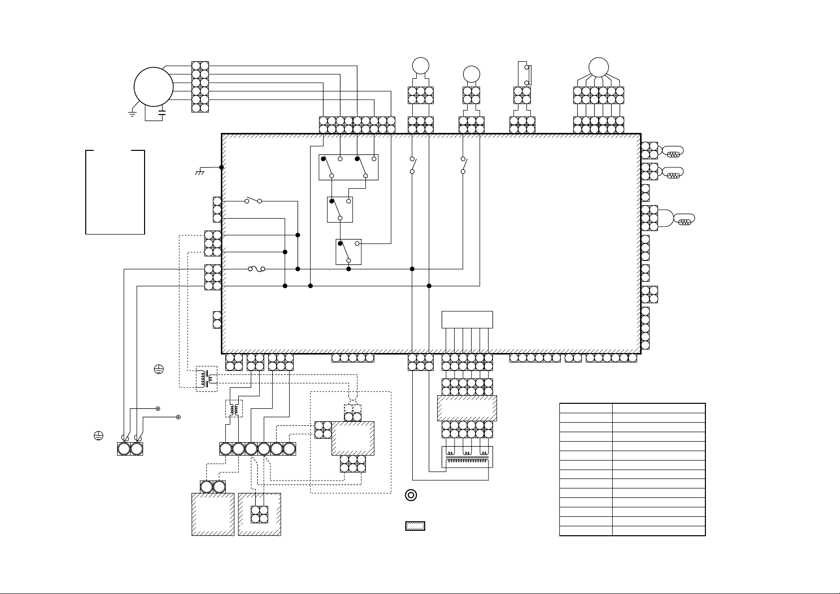
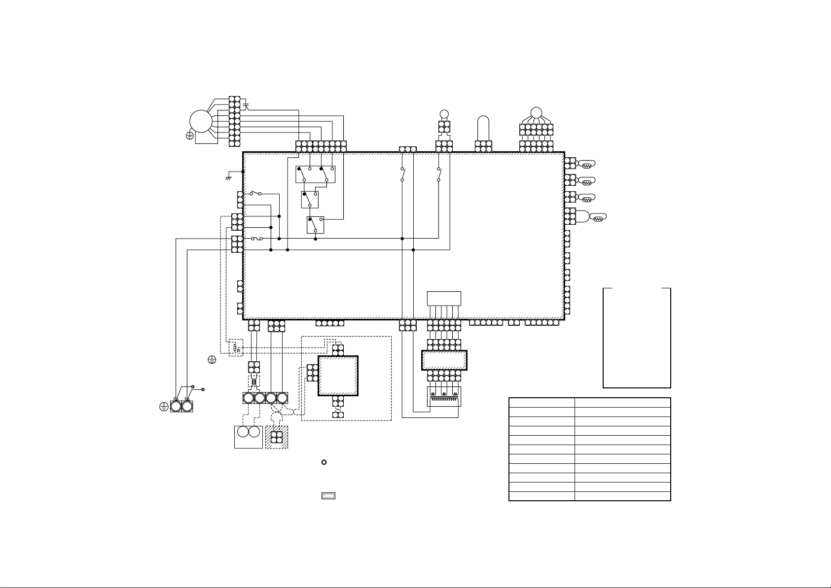
2-1-2. 2-way Air Discharge Cassette Type
Model: MMU-AP0071WH, AP0091WH, AP0121WH, AP0151WH, AP0181WH,
MMU-AP0241WH, AP0271WH, AP0301WH, AP0481WH
Page 15
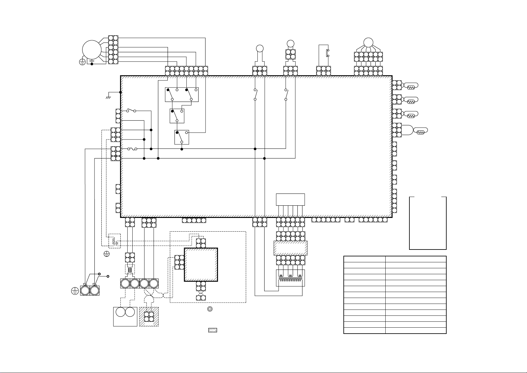
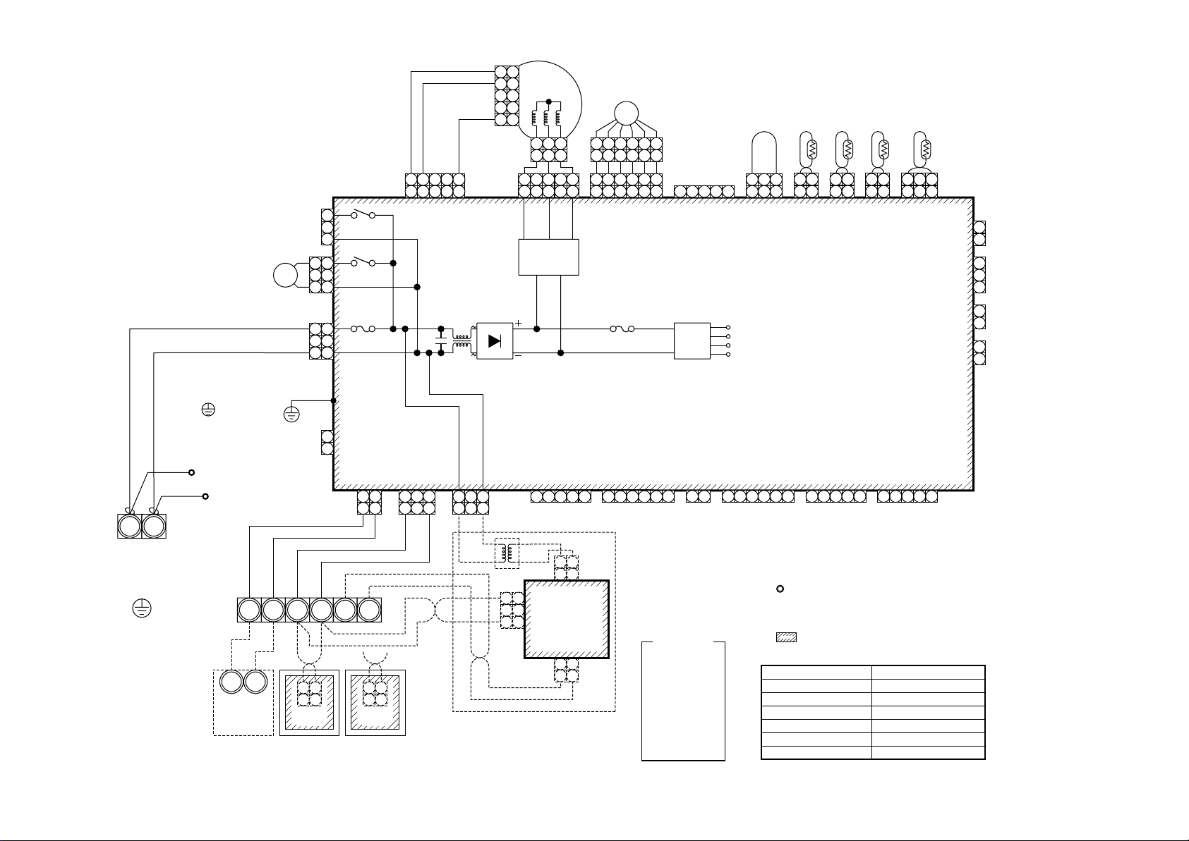
2-1-3. 1-way Air Discharge Cassette Type (Compact type)
Model: MMU-AP0071YH, AP0091YH, AP0121YH
15
Color
indication
RED : RED
WHI : WHITE
YEL : YELLOW
BLU : BLUE
BLK : BLACK
GRY : GRAY
PNK : PINK
ORN : ORANGE
BRW : BROWN
GRN : GREEN
Indoor unit
Earth screw
Flow selector
WHI
RED
RED
S(N)R(L)
Power supply
Single phase
220-240V 50Hz
220V 60Hz
FM
unit earth
screw
Closed end
connector
WHI
RC
2
4
6
CN304
(GRY)
CN309
(YEL)
AC IN
CN066
(WHI)
BLU
121
343
565
CN301
(BLK)
Heater
1
2
3
1
2
3
TR
Line Filter
1
Outdoor
unit
1
2
3
1
2
3
1
2
3
1
2
U
U2U
CN067
(BLK)
CN044
(BRW)
1 2
1 2
BLU
BLU
U
1
BLU
RY004
Fuse
T5.0A
CN040
(BLU)
1 2
1 2
BLU
BLK
BLK
BA
2
CN1
(WHI)
1 2
1 2
Remote controller
FAN
CN083
CN041
(BLU)
1 2 3
1 3
YX
AI-NET
central control
terminal
(WHI)
BLK
RED
9 8 7 6
9 8 7 6
HML UL
RY007
CN050
(WHI)
1 2 3 4 5
MCC-1401
1 2
CN01
(WHI)
1 2
1 1
Network
2 2
adaptor
CN03
P.C. board
(RED)
BLU
ORN
5 4 3 2 1
5 4 3 2 1
RY006
RY005
Network
adaptor
(Option)
2 1
CN02
(BLU)
233 1
YEL
RY002
DM
1 2 3
1 2 3
1 2 3
1 2 3
(BLU)
CN068
DP
RY001
LM
2 1
2 1
1 2 3
1 2 3
LM
(GRN)
CN033
2 1
2 1
1 2 3
1 2 3
Indoor control P.C. board
Power supply
circuit
CN074
(WHI)
CN075
(WHI)
1 2 3
1 2 3
1. indicates the terminal block, letter at inside
indicates the terminal number.
2. A dotted line and broken line indicate the wiring at site.
3. indicates the control P.C. board.
1 2 3
4 5 6
1 2 3 4 5 6
1 2 3 4 5 6
Sub P.C. board
MCC-1520
1 2 3 4 5 6
1 2 3 4 5 6
CN02
(YEL)
CN01
(WHI)
TR
CN061
(YEL)
1 2 3 4 5 61 2 3 4 5 6
FS
(RED)
CN030
FS
6 4 3
6 4 3
1 2 3
1 2 3
CN032
(WHI)
1 2
Fan drive
Symbol
FM
RC
TR
LM
TA
TC1,TCJ
RY001
RY002
RY004
RY005~007
FS
DM
PMV
PMV
1 2 5
1 2 5
4 5 6
4 5 6
CN082
CN104
(YEL)
CN102
(RED)
CN101
(BLK)
CN100
(BRW)
CN080
(GRN)
CN073
(RED)
CN070
(WHI)
CN081
(BLK)
CN060
(WHI)
1 2 3 4 5 6
Option
Fan motor
Running capacitor
Power transformer
Louver motor
Indoor temp sensor
Temp sensor
Flap motor control relay
Drain pump control relay
Heater control relay
Fan motor control relay
Float switch
Drain pump motor
Pulse Motor Valve
PMV
(BLU)
Parts name
2
2
1
2
2
1
2
3
1
2
1
2
1
2
3
4
5
121
121
121
33
PNL
EXCT
1
2
TA
TCJ
TC1
Filter
Page 16
16
Indoor unit
earth screw
220-240V 50Hz
FM
RC
Flow selector
R(L) S(N)
Power supply
single phase
220V 60Hz
1
2
313
4
4
5
5
6
6
P301
BLK
RY004
1
(GRY)
3
CN304
1
(YEL)
313
AC IN
CN066
(WHI)
CN044
(BRW)
unit earth
screw
Line Filter
Closed-end
connector
CN309
1
FUSE
T5.0A 250V~
313
(BLK)
CN067
1
2
1
CN040
2
EMG
TR
U1
U1 U2
Outdoor unit Remote Controller
CN041
(BLU)
(BLU)
2
1 233 1 2 3 4 5
112
1
BLU
BLU
BLK
2
112
U2 A B
2
112
CN1
RED BLK ORN BLU YEL
FAN
CN083
(WHI)
9 5 3 1
RY007
RC
BLK
3
1 1
5 3 1779
M LUL
H
RY006
RY005
CN050
(WHI)
CN01(WHI)
3
CN02
2
(BLU)
CN03(RED)
LM
2
112
113
RY001
Power supply
circuit
1 2 3 4 5 6 1 2 1 23 4 5 6 1 2 3 4 5 6
1 2 3 4 5 6
1 2 3 4 5 6
1 2 3 4 5 6
Sub P.C. board
MCC-1520
1 2 3 4 5 6
1 2 3 4 5 6
Network Adapter
2
112
112
X Y
(Option)
2
MCC-1401
CN068
(BLU)
RY002
CN074
(WHI)
DM
133
1
113
DM
3
1. Indicates the terminal bolock, letter.
Letter at inside indicates the terminal number.
2. A dotted line and broken line indicate
the wiring at side.
3. indicate the control p.c. board.
LM
3
CN033
(GRN)
Control P.C. board
for Indoor unit
CN075
(WHI)
CN02
(YEL)
CN01
(WHI)
TR
FS
FS
3
CN030
(RED)
113
MCC-1403
CN061
(YEL)
1 2 3 4 5 6
1 2 3 4 5 6
CN032
(WHI)
FAN
DRIVE
Symbol
FM
RC
TR
LM
TA
TC1,TC2,TCJ
RY001
RY002
RY005~007
FS
DM
PMV
PMV
1 234 56
1 234 56
CN060
(WHI)
OPTION
PMV
CN082
(BLU)
212
212
1
2
1
2
313
1
2
3
1
2
1
2
1
2
3
4
5
1
1
1
2
PNL
EXCT
FILTER
CN104
(YEL)
CN102
(RED)
CN101
(BLK)
CN100
(BRW)
CN080
(GRN)
CN073
(RED)
CN070
(WHI)
CN081
(BLK)
Parts name
Fan motor
Running capacitor
Transformer
Lover motor
Indoor temp sensor
Temp sensor
Louver control relay
Drain control relay
Fan motor control relay
Float switch
Drain pump motor
Pulse motor valve
TA
TCJ
TC2
TC1
Color
indication
RED : RED
WHI : WHITE
YEL : YELLOW
BLU : BLUE
BLK : BLACK
GRY : GRAY
PNK : PINK
ORN : ORANGE
BRW : BROWN
GRN : GREEN
Model: MMU-AP0151SH, AP0181SH, AP0241SH
Page 17
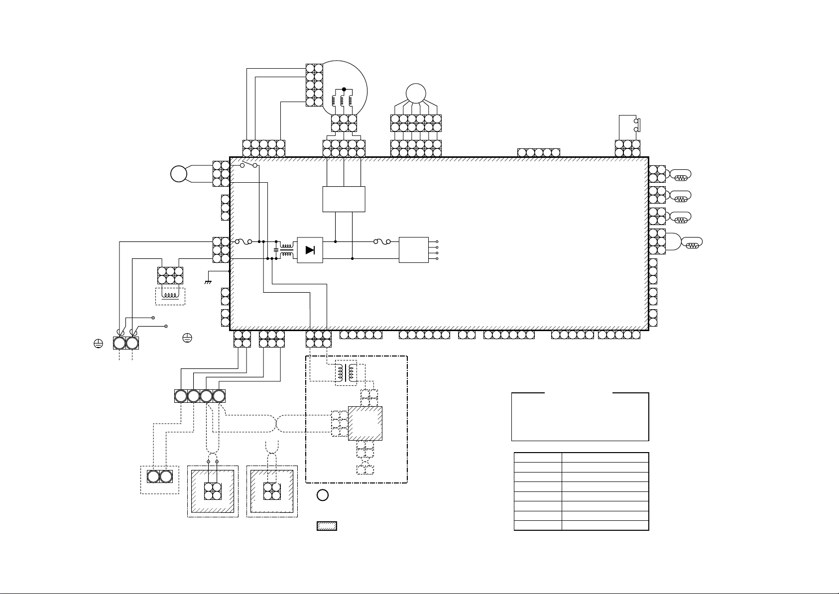
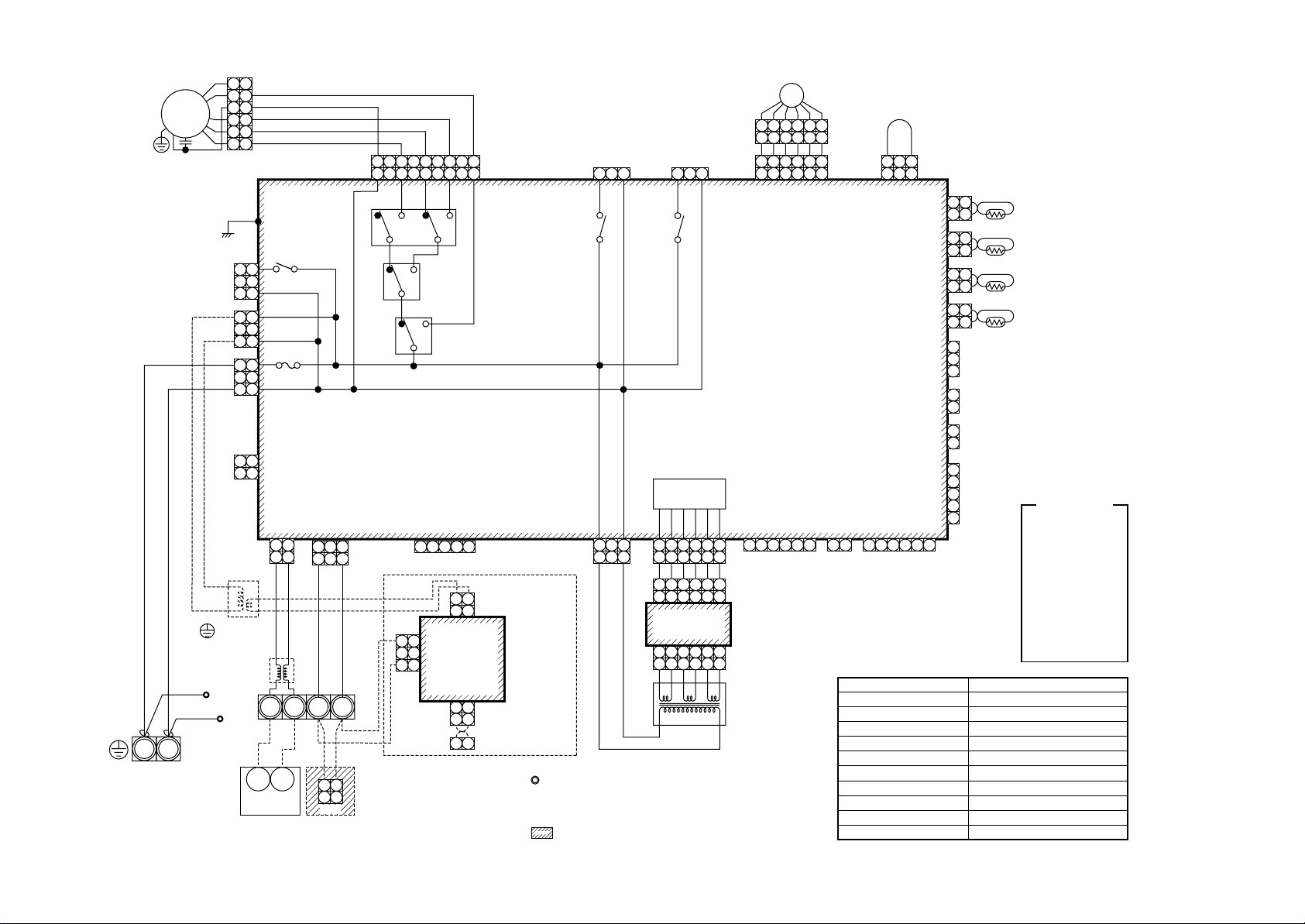
2-1-4. Concealed Duct Standard Type
Model: MMD-AP0071BH, AP0091BH, AP0121BH, AP0151BH, AP0181BH, AP0241BH
17
Indoor unit
S(N)R(L)
Earth screw
Indoor unit power supply
Single phase
220-240V 50Hz
220V 60Hz
RED
WHI
Closed end
connector
Outdoor unit
1 3
1 2 2
Reactor
WHI
Flow selector
U2U
1
DM
unit earth
screw
U
U
1
WHI
Wired remote
CN68
(BLU)
1
1
2
2
3
3
1
CN304
2
(GRY)
3
RED
1
1
CN67
2
2
(BLK)
3
3
WHI
BLK
1
CN66
(WHI)
2
1
CN44
(BRW)
2
BA
2
BLK WHI BLK
CN1
(WHI)
1 2
1 2
controller
5
CN334
RY302
(WHI)
Fuse
T6.3A
250V~
P301
CN41
CN40
(BLU)
(BLU)
1 2 3
1 2
1 2
1 2 3
BLK
BLU
BLU
1 2
1 2
Adaputor for wired
remote controller
11223445
BLK
BLK
WHI
CN001
(WHI)
545
FM
4
11
PMV
6 4 3 1 2 5
6 4 3 1 2 5
1 2 3 4 5 6
1 2 3 4 5 6
Fuse
T3.15A
250V~
4 5 6
T10
Power
supply
circuit
~
~
CN309
(YEL)
CN333
(WHI)
1 2 3
1 2 3
1 3
1 3 5
Motor drive
circuit
+
–
5
CN50
(WHI)
1 2 3
TR
CN02
(BLU)
3 3
2 2
1 1
CN01
(WHI)
1 2
1 2
Network
adaptor
P.C. board
1 2
1 2
Network
adaptor
(Option)
CN03
(RED)
X Y
1. indicates the terminal block, letter at inside
indicates the terminal number.
2. A dotted line and broken line indicate the wiring at site.
3. indicates the control P.C. board.
CN61
(YEL)
CN82
(BLU)
Indoor control P.C. board
DC20V
DC15V
DC12V
DC7V
CN32
(WHI)
CN60
(WHI)
1 21 2 3 4 5 61 2 3 4 51 2 31 2 3
(Signal output)(Fan drive)
1 2 3 4 5
Color identification
RED : RED
WHI : WHITE
YEL : YELLOW
BLU : BLUE
BRW : BROWN
Symbol
FM
TA
TC1,TC2,TCJ
DM
FS
RY302
PMV
CN33
(WHI)
CN81
(BLK)
1 2 3 4 5
1 2 3 4 5
BLK : BLACK
GRY : GRAY
PNK : PINK
ORN : ORANGE
GRN : GREEN
Parts name
Fan motor
Indoor temp sensor
Indoor temp sensor
Drain pump motor
Float switch
Drain pump control relay
Pulse Motor Valve
CN20
(BLU)
3 1
321
CN104
(YEL)
CN102
(RED)
CN101
(BLK)
CN100
(BRN)
CN80
(GRN)
CN73
(RED)
CN70
(WHI)
FS
CN34
(RED)
2
2
2
2
1
2
3
1
2
1
2
121
121
121
121
33
PNL
EXCT
MMD-AP0271BH, AP0301BH, AP0361BH, AP0481BH, AP0561BH
TA
TCJ
TC2
TC1
Page 18
18
Color
indication
RED : RED
WHI : WHITE
YEL : YELLOW
BLU : BLUE
BLK : BLACK
GRY : GRAY
PNK : PINK
ORN : ORANGE
BRW : BROWN
GRN : GREEN
RED
WHI
Closed
end
connector
Indoor unit
Earth screw
S(N)R(L)
Power supply
Single phase
220-240V 50Hz
220V 60Hz
(BLK)
CN304
(GRY)
1
2
3
1
2
3
TR
Flow selector
unit earth
screw
T10A,250V~
Closed end
connector
Spark
killer
87
43F1
FAN
CN083
P301
1
RY004
2
3
1
CN309
2
(YEL)
3
CN067
(BLK)
1
2
3
1
2
YEL
CN066
(WHI)
CN044
(BRW)
EMG
1
Outdoor unit
REDRED F
RED
6
4
Fuse
T5.0A
OC
U
U2U
43F1
WHI
1 2 3 4
CN040
(BLU)
1 21 2
1 2
RC
U
2
1
Remote controller
5
43F1
3
RED
GRY
1 2 3 4
WHI
RED
(WHI)
CN041
1 2 3
1 3
1 2
1 2
REDWHI
9 8 7 6
9 8 7 6
HML UL
RY007
(BLU)
BA
CN1
CN02
(WHI)
(BLU)
RC
GRY
FM
4 2
5 4 3 2 1
RY006
RY005
CN050
(WHI)
1 2 3 4 5
1 2
CN01
(WHI)
1 2
3 3
2
1 1
1 2
1 2
X Y
WHI
F1F2F3F
BLU
RY002
Network adaptor
(Option)
MCC-1401
CN03
(RED)
ORN
BLK
(Option)
DP
1 2 3
1 2 3
DP
(BLU)
CN068
RY001
1 2 3
1 2 3
LM
(GRN)
CN033
1 2 3
1 2 3
FS
CN030
(RED)
TA
1 2
1 2
CN104
(YEL)
Indoor control P.C. board
Power
supply
circuit
CN074
(WHI)
1 2 3
1 2 3
1 2 3
4 5 6
1 2 3 4 5 6
1 2 3 4 5 6
Sub P.C. board
MCC-1520
1 2 3 4 5 6
1 2 3 4 5 6
1. indicates the terminal block, letter at inside indicates the terminal number.
2. A dotted line and broken line indicate the wiring at site.
3. indicates the control P.C. board.
4. When attaching a drain pump, exchange CN030 connector with a connector
of the float switch.
5. A part is connected to the terminal block.
When exchanging to the outside static pressure necessary at the local site,
check the terminal No. and lead color of the fan motor in the below diagram,
4
BRN
and then exchange the lead wire indicated by the arrow mark ( ),
6. Pay attention to change static pressure because the outside static pressure of
H tap in 50 or 60Hz.
Wired for MMD-AP0481 only
(BRN Wire)
Motor over heating protection switch
CN075
(WHI)
BLK
WHI
GRY
RED
1 2 3 4 5 61 2 3 4 5 6
T10
CN02
(YEL)
CN01
(WHI)
TR
CN061
(YEL)
49F
TCJ
1 2
1 2
CN102
(RED)
CN032
(WHI)
1 2
Fan drive
BLU
ORN
BRN
1 2
1 2
CN060
(WHI)
TC1
1 2 3
1 2 3
CN080
(GRN)
CN073
(RED)
CN070
(WHI)
CN081
(BLK)
CN082
(BLU)
TC2
CN101
(BLK)
1 2 3 4 5 6
Option
Sold
separately
CN100
(BRN)
1
2
PNL
3
1
EXCT
2
1
Filter
2
1
2
3
4
5
6
6
5
5
4
4
3
3
2
2
1
1
Symbol
FM
RC
TR
TA
TC1,TC2,TCJ
RY005~007
RY001
RY002
PMV
F
43F1
DM
FS
5
5
2
2
1
1
PMV
3
3
4
4
6
6
Parts name
Fan motor
Running capacitor
Transformer
Indoor temp sensor
Temp sensor
Fan motor control relay
Flap motor control relay
Drain control relay
Pulse Motor Valve
Fuse
Fan motor control relay
Drain pump motor
Float switch
2-1-5. Concealed Duct High Static Pressure Type
Model: MMD-AP0181H, AP0241H, AP0271H, AP0361H, AP0481H
Page 19
FM
2-1-6. Under Ceiling Type
Model: MMC-AP0151H, AP0181H, AP0241H, AP0271H, AP0361H, AP0481H
PMV
1
2
3
4
6
4
6
5
1
2
3
5
LM
1 2 3 4 5
1 2 3 4 5
FS
19
Indoor unit
Earth screw
Power supply
single phase
200-240V 50Hz
200V 60Hz
RED
S(N)R(L)
WHI
RED
WHI
Flow selector
unit earth
screw
Closed end
terminal
DM
U2U
1
Outdoor unit
CN68
(BLU)
1
1
2
2
3
3
CN304
1
(GRY)
2
3
1
1
CN67
2
2
(BLK)
3
3
P301
BLK
1
2
BLU
121
BLU
2
BLK
121
BLK
33
U2U
1
WHI BLK BLKWHI
1 2
1 2
Wired remote
controller
RY302
RY303
Fuse
T6.3A
250V~
CN66
(WHI)
CN40
(BLU)
CN41
(BLU)
BA
CN1
(WHI)
5 4 1
5 4 3 2 1
~
~
CN309
(YEL)
1 2 3
BLK
WHI
CN001
(WHI)
1 2
1 2
Adpter for wireless
remote controller
CN334
1 2 3 4 5
(WHI)
1 2 3 4 5
Motor drive
circuit
+
–
CN50
(WHI)
4 5 6
1. indicates the terminal block, letter at inside
2. A dotted line and broken line indicate the wiring at site.
3. indicates the control P.C. board.
CN333
(WHI)
Fuse
TR
3 3
2 2
1 1
CN02
(BLU)
CN61
(YEL)
T10
CN01
(WHI)
T3.15A
Network
adaptor
P.C. board
1 2
1 2
1 2
1 2
Network
adaptor
(Option)
CN03
(RED)
Power
supply
circuit
CN32
(WHI)
X Y
indicates the terminal number.
1 2 3 4 5
1
2
3
CN82
6
(BLU)
4
5
6
Indoor control P.C. board
DC20V
DC15V
DC12V
DC7V
CN60
(WHI)
1 21 2 3 4 5 6
Option GRLFandrive
1 2 3 4 5
1 2 3 4 5
CN81
(BLK)
1 2 3 4 51 2 3 4 51 2 31 2 3
Sold
separately
CN33
(WHI)
RED : RED
WHI : WHITE
YEL : YELLOW
BLU : BLUE
BRW : BROWN
TC,TC2,TCJ
1 3
123
CN20
(BLU)
1 2 3 4 5
Color identification
Symbol
FM
TA
LM
RY302
DM
FS
CN34
(RED)
CN104
(YEL)
CN102
(RED)
CN101
(BLK)
CN100
(BRW)
CN80
(GRN)
CN73
(RED)
CN70
(WHI)
Fan motor
Indoor temp sensor
Temp sensor
Louver motor
Drain control relay
Drain pump motor
Float switch
121
2
121
2
121
2
121
2
33
1
PNL
2
3
1
EXCT
2
1
FILTER
2
BLK : BLACK
GRY : GRAY
PNK : PINK
ORN : ORANGE
GRN : GREEN
Parts name
TA
TCJ
TC2
TC1
Page 20
2-1-7. High Wall T ype
545
4
FM
Model: MMK-AP0071H, AP0091H, AP0121H, AP0151H, AP0181H, AP0241H
20
RED
WHI
R(L) S(N)
Power supply
single phase
220-240V 50Hz
220V 60Hz
Indoor unit
Earth screw
Flow selector
unit earth
screw
Closed-end
connector
RED
WHI
U1 U2
Outdoor
unit
U1 U2
1
CN68
(BLU)
3
1
LM
CN304
(GRY)
1
3
CN67
(BLK)
P301
BLK
CN66
(WHI)
313
1
3
1
2
A B X Y
WHI BLK
2
112
CN1
(WHI)
Wired remote
controller
CN334
(WHI)
RY302
RY303
FUSE
T6.3A 250V~
CN40
(BLU)
1 231 3
BLU
BLU
BLK
GRY
GRY
WHI BLK
2
112
CN001
(WHI)
Adapter for
wireless remote
controller
BLK
5
CN41
(BLU)
1 21 2
11
1 2 3
1 2 3
CN333
1 2 3 4 5 6
1
223445
1 3
BLK
WHI
(WHI)
CN309
(YEL)
TR
3
1 1
1 3
1 3 5
Motor drive
circuit
CN50
(WHI)
1 2 31 3
CN01(WHI)
3
CN02
2
(BLU)
CN03(RED)
5
4 5
2
112
2
112
1
1 2 3 4 5 6
T3.15A 250V~
Network Adapter
(Option)
MCC-1401
PMV
1 234 56
1 234 56
CN82
(BLU)
FUSE
CN61
(YEL)
1 2 3 4 5
CN33
(WHI)
Power
supply
circuit
CN32
(WHI)
6
1 2
Fandrive
Color
indication
RED : RED
WHI : WHITE
YEL : YELLOW
BLU : BLUE
BLK : BLACK
GRY : GRAY
PNK : PINK
ORN : ORANGE
BRW : BROWN
GRN : GREEN
TC2
TCJ
113
CN34
(RED)
TA
3
21212121212
CN104
CN102
(YEL)
(RED)
CN101
(BLK)
TC1
1
112 31 2 3 4 5
CN100
(BRW)
Control P.C. board
for Indoor unit
DC20V
DC15V
DC12V
DC7V
CN60
(WHI)
1 2 3 4 5 6
Option
MCC-1402
CN81
(BLK)
1 2 3 4 5
CN20
(BLU)
1 2 3 4 5
1. Indicates the terminal bolock.
Letter at inside indicates the terminal number.
2. A dotted line and broken line indicate
the wiring at side.
3. indicate the control p.c. board.
Symbol
FM
TA
TC1,TC2,TCJ
PMV
LM
RY303
Parts name
Fan motor
Indoor temp sensor
Temp sensor
Pulse motor valve
Lover motor
Louver control relay
3
CN103
(GRN)
CN080
(GRN)
CN73
(RED)
CN70
(WHI)
1
2
1
2
3
1
2
1
2
EXCT
Page 21
21
Indoor unit
earth screw
220-240V 50Hz
AC IN RED
R(L) S(N)
Power supply
single phase
220V 60Hz
FM
RC
WHI
Flow selector
unit earth
screw
RED
Closed-end
connector
WHI
2
323
4
4
5
5
6
6
P301
(BLK)
313
313
T5.0A 250V~
313
212
CN040
(BLU)
U1
RY004
(GRY)
CN304
(YEL)
CN309
FUSE
CN041
(BLU)
2
1 233 1 2 3 4 5
112
1
BLU
BLU
BLK
U2 A B
1
1
1
CN067
(BLK)
CN066
(WHI)
1
TR
Line Filter
U1 U2
Outdoor unit Remote Controller
112
CN1
RED BLK ORN BLU YEL
FAN
CN083
(WHI)
9 5 3 1
RY007
RC
BLK
2
5 3 1779
M LUL
H
RY006
RY005
CN050
(WHI)
3
3
CN02
2
(BLU)
1 1
2
112
CN01(WHI)
CN03(RED)
2
112
X Y
1
113
DP
3
3
1 3
RY001
Power supply
circuit
1 2 3 4 5 6 1 2 1 23 4 5 6 1 2 3 4 5 6
1 2 3 4 5 6
1 2 3 4 5 6
1 2 3 4 5 6
Sub P .C. board
MCC-1520
1 2 3 4 5 6
1 2 3 4 5 6
Network Adapter
(Option)
CN068
(BLU)
RY002
CN074
(WHI)
LM
MCC-1401
1. Indicates the terminal bolock.
Letter at inside indicates the terminal number.
2. A dotted line and broken line indicate
the wiring at side.
3. indicate the control p.c. board.
(GRN)
1 2 3 4 5 6
1 2 3 4 5 6
CN033
Control P.C. board
for Indoor unit
MCC-1403
CN061
CN075
(YEL)
(WHI)
T10
CN02
(YEL)
CN01
(WHI)
TR
PMV
2-1-8. Floor Standing Cabinet Type
Model: MML-AP0071H, AP0091H, AP0121H, AP0151H, AP0181H, AP0241H
1 234 56
1 234 56
PMV
CN082
(BLU)
CN032
(WHI)
112 3
CN060
(WHI)
FS
3
CN030
(RED)
CN104
(YEL)
CN102
(RED)
CN101
(BLK)
CN100
(BRN)
CN080
(GRN)
CN073
(RED)
CN070
(WHI)
CN081
(BLK)
212
212
1
2
212
1
2
3
1
2
1
2
1
2
3
4
5
1
1
1
2
1
PNL
EXCT
FILTER
TA
TCJ
TC2
TC1
Color
indication
RED : RED
WHI : WHITE
FAN
DRIVE
OPTION
YEL : YELLOW
BLU : BLUE
BLK : BLACK
GRY : GRAY
PNK : PINK
ORN : ORANGE
BRW : BROWN
GRN : GREEN
Symbol
FM
RC
TR
TA
TC1,TC2,TCJ
RY001
RY002
RY004
RY005~007
PMV
Parts name
Fan motor
Running capacitor
Transformer
Indoor temp sensor
Temp sensor
Louver control relay
Drain control relay
Heater control relay
Fan motor control relay
Pulse motor valve
Page 22
22
Indoor unit
earth screw
RED
WHI
RED
R(L) S(N)
Power supply
single phase
220-240V 50Hz
220V 60Hz
Flow selector
unit earth
screw
Closed-end
connector
WHI
WHI
1
GRN
1
3
3
2
2
4
4
FM
5
5
6
6
RED
RED BLK ORN BLU YEL
FAN
CN083
(WHI)
9 5 3 1
RC
5 3 1779
For AP0071BH,AP0091BH,AP0121BH
2
112
Network
adapter
3
CN02
2
(BLU)
2
112
CN01(WHI)
CN03(RED)
MCC-1401
(Option)
1 1
2 2
CN03
(RED)
TR
U1 U2
U1 U2
Outdoor unit
A B X Y
2
112
CN1
Remote Controller
3
1 1
1. Indicates the terminal bolock.
Letter at inside indicates the terminal number.
2. A dotted line and broken line indicate
the wiring at side.
3. indicate the control p.c. board.
GRN
R301
(BLK)
AC IN
1
1
EMG
FM
RED
WHI
1
3
313
T5.0A 250V~
313
1
CN066
(WHI)
2
1
CN044
(BRW)
2
(GRY)
CN304
(YEL)
CN309
FUSE
(BLK)
CN067
RC
RY004
CN040
(BLU)
112
2
2
424
5
5
6
6
3
3
RED BLK ORN BLU YEL
FAN
CN083
(WHI)
CN041
(BLU)
1 233 1 2 3 4 5
1
5 3 1779
9 5 3 1
M LUL
H
RY007
RY006
indication
RED : RED
WHI : WHITE
YEL : YELLOW
BLU : BLUE
BLK : BLACK
GRY : GRAY
PNK : PINK
ORN : ORANGE
BRW : BROWN
GRN : GREEN
RY005
CN050
(WHI)
Color
CN068
(BLU)
RY002
CN074
(WHI)
133
1
113
3
3
CN033
(GRN)
113
RY001
Control P.C. board
for undoor unit
Power supply
circuit
CN075
MCC-1520
(WHI)
CN02
(YEL)
CN01
(WHI)
TR
1 2 3 4 5 6 1 2 1 23 4 5 6 1 2 3 4 5 6
1 2 3 4 5 6
1 2 3 4 5 6
1 2 3 4 5 6
Sub P.C. boar d
1 2 3 4 5 6
1 2 3 4 5 6
MCC-1403
CN061
(YEL)
112 3
CN030
(RED)
Symbol
FM
RC
TR
TA
TC1,TC2,TCJ
RY001
RY002
RY004
RY005~007
PMV
Fan motor
Running capacitor
Transformer
Indoor temp sensor
Temp sensor
Louver control relay
Drain control relay
Heater control reley
Fan motor control relay
Pulse motor valve
3
CN032
(WHI)
FAN
DRIVE
PMV
1 234 56
1 234 56
1 2 3 4 5 6
1 2 3 4 5 6
CN082
CN104
(BLU)
CN102
(RED)
CN101
CN100
(BRW)
CN080
(GRN)
CN073
(RED)
CN070
CN081
CN060
(WHI)
OPTION
Parts name
(YEL)
(BLK)
(WHI)
(BLK)
PMV
212
212
1
2
131
2
1
2
3
1
2
1
2
1
2
3
4
5
1
1
1
2
3
PNL
EXCT
FILTER
TCJ
TC2
2-1-9. Floor Standing Concealed Type
Model: MML-AP0071BH, AP0091BH, AP0121BH, AP0151BH, AP0181BH, AP0241BH
TA
TC1
Page 23
23
Indoor unit
earth screw
RED
WHI
R(L) S(N)
Power supply
single phase
220-240V 50Hz
220V 60Hz
FM
Flow selector
unit earth
screw
Closed-end
connector
1
RC
313
4
4
5
5
6
6
787
BRW
P301
(BLK)
1
(GRY)
3
CN304
1
(YEL)
313
CN309
AC IN
1
T5.0A 250V~
313
(BLK)
CN067
CN066
(WHI)
1
2
CN044
(BRW)
1
CN040
2
(BLU)
EMG
112
BLU
TR
112
Line Filter
U1
U1 U2
Outdoor unit Remote Controller
CN083
RY004
FUSE
CN041
(BLU)
2
1 233 1 2 3 4 5
1
BLU
BLK
2
U2 A B
2
112
CN1
RED BLK ORN BLU YEL
FAN
(WHI)
9 5 3 1
RY007
RC
BLK
3
1 1
LM
1
221
5 3 1779
M LUL
H
RY006
RY005
CN050
(WHI)
CN01(WHI)
3
CN02
2
(BLU)
CN03(RED)
Network Adapter
2
112
2
112
MCC-1401
X Y
(Option)
CN068
(BLU)
RY002
CN074
(WHI)
1
113
DP
3
RY001
3
LM
3
CN033
(GRN)
113
Control P.C. board
Power supply
circuit
CN075
MCC-1520
(WHI)
CN02
(YEL)
CN01
(WHI)
TR
1 2 3 4 5 6 1 2 1 23 4 5 6 1 2 3 4 5 6
1 2 3 4 5 6
1 2 3 4 5 6
1 2 3 4 5 6
Sub P.C. board
1 2 3 4 5 6
1 2 3 4 5 6
1. Indicates the terminal bolock, letter.
Letter at inside indicates the terminal number.
2. A dotted line and broken line indicate
the wiring at side.
3. indicate the control p.c. board.
FS
3
CN030
(RED)
112 3
for Indoor unit
MCC-1403
CN061
(YEL)
PMV
1 2 3 4 5 6
1 2 3 4 5 6
CN060
CN032
(WHI)
(WHI)
FAN
OPTION
DRIVE
Symbol
FM
RC
TR
LM
TA
TC1,TC2,TCJ
RY001
RY002
RY005~007
PMV
2-1-10. Floor Standing Type
Model: MMF-AP0151H, AP0181H, AP0241H, AP0271H, AP0361H, AP0481H, AP0561H
1 234 56
1 234 56
PMV
CN082
(BLU)
TA
1
CN104
(YEL)
212
TCJ
1
CN102
(RED)
212
TC2
1
1
CN101
(BLK)
2
2
131
CN100
(BRW)
CN080
(GRN)
CN073
(RED)
CN070
(WHI)
CN081
(BLK)
TC1
3
1
2
PNL
3
1
EXCT
2
1
FILTER
2
1
2
3
4
5
Color
indication
RED : RED
WHI : WHITE
YEL : YELLOW
BLU : BLUE
BLK : BLACK
GRY : GRAY
PNK : PINK
ORN : ORANGE
BRW : BROWN
GRN : GREEN
Parts name
Fan motor
Running capacitor
Transformer
Lover motor
Indoor temp sensor
Temp sensor
Louver control relay
Drain control relay
Fan motor control relay
Pulse motor valve
Page 24
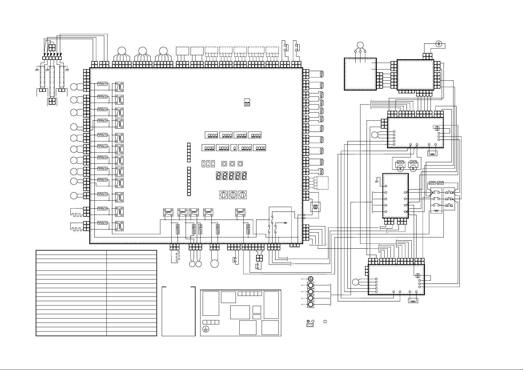
24
112
2
U1 U2 U3 U4 U5 U6
CN309(WHI)
Outdoor
unit
SV61
SV42
CN311(BLU)
SV41
CN310(WHI)
SV51
CN312(WHI)
SV2
CN324(RED)
SV3A
CN313(YEL)
SV3B
CN314(BLK)
SV3C
CN322(WHI)
SV11
CN319(WHI)
SV12
CN316(WHI)
Heater 1
CN315(BLU)
T Heater 2
Symbol
U1 U2 U5 U6
Indoor
unit
U1 U2
U3 U4
Central remote
controller
CM1, CM2
PMV1, PMV2, PMV3
SV2, SV41, SV42, SV51, SV3A, SV3B, SV3C, SV3D ,
SV3E, SV61, SSV11, SV12
4WV1
COMP1, COMP2
TS1, TS2
TD1, TD2
TE1
TO
TK1, TK2, TK3, TK4
TL
HEATER1, HEATER2, ACCUM HEATER
FM
PS
PD
63H1, 63H2
MG-SW
OCR
BRW
BRW
BLU
BLU
112
2
7
CN01
CN03
(BLU)
(WHI)
5
BLU
313
BLU
BLU
BLU
BLU
BLU
BLU
BLU
BLU
BLU
BLU
BLU
BLU
BLU
BLU
BLU
BLU
BLU
BLU
BLU
CR500
1
7
7
CR503
5
5
3
3
CR502
1
1
4
3
CR504
212
1
313
CR506
1
313
CR507
1
313
CR508
1
313
CR509
1
4
4
3
3
CR513
2
1
1
313
CR514
3
CR516
131
3
CR517
131
PMV1
WHI
WHI
RED
BRN
BLU
ORN
YEL
WHI
CN300
(WHI)
RY500
RY503
RY502
RY504
RY506
RY507
RY508
RY509
RY513
RY514
RY516
RY517
Parts name
RED
6 5 4 3 2 1
6 5 4 3 2 1
11223
6 5 4 3 2 1
6 5 4 3 2 1
3
Compressor
Pulse motor valve
2-way valve coil
4-way valve coil
Compressor case thermo.
Pipe temp. sensor (Inlet)
Pipe temp. sensor (Outlet)
Heat exchange temp. sensor
Air temp. sensor
Oil temp. sensor
Liquid temp. sensor
Case heater, 230V, 26W
Fan motor (DC)
Low pressure sensor
High pressure sensor
High pressure switch
Magnet switch
Overcurrent relay
BRN
PMV2
BLU
CN301
(WHI)
ORN
YEL
WHI
PMV3
RED
BRN
BLU
ORN
6 5 4 3 2 1
6 5 4 3 2 1
CN302
(RED)
Pressure
Pressure
Sensor
Sensor
PS
PD
RED
BLK
WHI
RED
YEL
WHI
1 2
1 2
BRN
Accumulator
heater
Color
indication
RED : RED
WHI : WHITE
YEL : YELLOW
BLU : BLUE
BLK : BLACK
GRY : GRAY
PNK : PINK
ORN : ORANGE
BRN : BRWN
VLT : VIOLET
BLK
4 3 2
4 3 1
4 3 2 1
4 3 2 1
CN501
CN500
(RED)
(WHI)
Interface Control P.C. Board
MCC-1429
1
2
3
(Srvice)
4
5
6
CN800
1
CN30
2
3
4
5
6
7
8
9
CN802
Flash
RY510
CR
510CR518
4
33221
CN321
(RED)
4
1
BLK
BLK
BLK
BLK
SV3ESV
3D
Option
Board
WHI
4 3 2 1
4 3 2 1
CN508
(RED)
SW11
SW06
CN31
RY521RY511
CN323
(WHI)
Noise filter
P.C. board
MCC-1366
L1L2L3N
4 3 2 1
4 3 2 1
431ON2
431ON2
SW07
CN32
SW01
CR521 CR519CR511
1 3
CN317
(BLU)
1 3
BLK
BLK
4WV1
Power supply
terminal
Option
Option
Board
Board
4 3 2 1
4 3 2 1
CN509
CN510
(BLK)
(WHI)
4
31ON2
SW13
SW12
1
431ON2
ON
SW09
SW08
SW06
SW05SW04
D603D602D601D600 D604
SW02 SW03
RY519RY518
CN307(WHI)
4 3 2 1
2 1
ORN
ORN
Comp2
Parts layout
U1U2U3U4U5U
Fan IPDU
Connecting terminal
MCC-896
Power supply
for fan
MCC-1439
Comp. IPDU
MCC-1502
ON
SW30
431ON2
431ON2
CN305(RED)
5 3 1 3 17
7 5
RED
BLU
No.1
Option
Board
4 3 2 1
455 3 2 1
CN513
(BLU)
4
31ON2
SW14
SW10
3
BLK BLK
3 1
3 1
ORN
Comp1
MGSW
OCR
Option
Board
4 3 2 1
4 3 2 1
CN512
(BLU)
431ON2
T6.3A
FUSE
1
1
RED
L1L2L3
ORN
6
Interface
control
P.C. board
(I/F)
MCC-1429
Comp. IPDU
No.2
MCC-1502
21
WHI
T6.3A
FUSE
332
BLK
T6.3A
FUSE
4
4
GRY
N
1 3
1 3
CN306
(WHI)
CN400
(WHI)
FM
63H1
63H2
1 3
1 3
BLU(BLK)
313
CN308
(BLU)
CN502
(WHI)
313
CN503
(PNK)
212
CN504
(WHI)
212
CN522
(BLK)
212
CN505
(GRN)
212
CN507
(YEL)
313
CN514
(BLK)
313
CN515
(GRN)
313
CN516
(RED)
313
CN523
(YEL)
212
CN521
(WHI)
4 4
313
CN511
(GRN)
2 2
313
CN100
(BLK)
CN402
CN401
CN600(WHI)
5 5
4 4
313
2 2
CN325
(YEL)
Option
Power Supply
3phase
380-415V 50Hz
1. The two-dot chain line indicates wiring at the local site, and the dashed line indicates
2. , , and indicate the terminal board and the numerals indicate the terminal numbers.
3. indicates P.C. board.
TD1
(YEL)
BLU(BLK)
1
BLU(BLK)
TD2
(RED)
BLU(BLK)
1
BLK
TS1
BLK
(GRY)
1
BLK
TS2
BLK
1
BLK
TE1
BLK
(BLK)
1
BLK
TO
BLK
(BLK)
1
BLU(BLK)
TK1
(BLK)
BLU(BLK)
1
BLU(BLK)
TK2
(BLU)
BLU(BLK)
1
BLU(BLK)
TK3
(BLU)
BLU(BLK)
1
BLU(BLK)
TK4
(GRN)
BLU(BLK)
1
BLK
TL
BLK
(WHI)
1
Option
board
1
BLU
BLU
1
Transformer
WHI
RED
1
PNK
RED
BLU
WHI
BLK
Earth screw
RED
L1
WHI
L2
BLK
L3
GRY
N
accessories sold separately and service wires, respectively.
* Be sure to fix the electric parts cover surely with two screws.
(Otherwise water enters into the box resulting in a trouble.)
RED
WHI
BLK
UVW
FAN IPDU
P.C. Board
MCC-896, 897
CN25
(WHI)
1
3
BLK
WHI
CM2
RED
YEL
BLU
YEL
–
+
CN01
(WHI)
BLU
CM1
3 1
3 1
CN26
(BLU)
RED
WHI
BLK
GRY
W
V
U
5
5
4
4
3
3
2
2
1
1
CN25
(WHI)
BLK
WHI
RED
YEL
BLU
BLK
5 4 1
5 4
CN11
CN10
CN09
CN22
CN23
BLU
313
YEL
1
BLK
5
5
WHI
4
4
BLU
3
3
RED
2
2
PNK
1
1
3 1
3 1
1 1
2 2
CN26
(BLU)
3 3
W
CN11
V
CN10
U
CN09
CN22
CN23
YEL
YEL
+ – + –
Noise filter
P.C. board
MCC-1366
CN21
CN01
CN02
CN03
CN04
CN23(BLU)CN22(WHI)
1 3
1 3
PNK
RED
BLU
WHI
BLK
3 2
3 2 1
CN06
(WHI)
IPDU Board (2)
MCC-1502
CN15 CN13
YEL
BLU
CN506(BLK)
CN500
(WHI)
Power supply
P.C. board for FAN
MCC-1439
CN503
(WHI)
CN504 CN505(RED)
1 2
1 2
BLK
WHI
PNK
RED
BLU
PNK
1 2 5
3 2
5 4 1
1 2
3 2 1
5 4
CN06
(WHI)
IPDU P.C. Board (1)
MCC-1502
CN15
CN13
BLU
BLK
BLK
BLK
RED
RED
CN17
WHI
CN18
BLK
BLK
CN19
GRY
GRY
CN20
GRY
1 3
1 3
PNK
RED
BLU
WHI
BLK
3 1
3 2
5 4 1
3 1
3 2 1
5 4
CN18
CN17
(RED)
(BLK)
CN03
L1
CN02
L2
CN01
L3
CN08
WHI
Reactor
BLU
CN07
WHI
RED
CN18
(RED)
CN21
WHI
RED
BLU
YEL
1
331
CN502
(BLU)
CN501
(RED)
3 4
53 41 2 5
3 4 5
WHI
BLK
BLU
3 4
3 4 5
CN03
CN02
CN01
Reactor
PTC Themistor
BLK
WHI
RED
–
+
313
1
5
5
GRY
3
3
RED
1
1
BLU
YEL
RED
3 1
3 1
CN17
(BLK)
BLK
L1
WHI
L2
RED
L3
CN20
WHI
RED
RED
Mg-SW OCR
1
2
4
3
5
6
A1 A2
2-2. Outdoor Unit
Model: MMY-MAP0801FT8, MAP1001FT8, MAP1201FT8
2
4
6
Page 25

2-3. Flow Selector Unit (FS Unit)
Model: RBM-Y1121FE, Y1801FE
25
Flow Selector Unit
RBM-Y1801FE Only
SVSSVS SVSS
SVDCOM SVS
BLU
ORN
WHI
SVDD
SVDD
YEL
SVD
SVSS
BRW
Earth Screw
1
3
1
3
1
CN01
(RED)
Control P.C. Board
MCC-1431
3
1
CN02
(GRN)
53
CN10
(WHI)
45
312
321
Indoor Unit
9
7
9
75
54
Control P.C. Board
for indoor unit
51234
CN81
45213
(BLK)
11
33
CN67
(BLK)
Power Supply
Single Phase
220-240V 50Hz
S(N)R(L)
Indoor Unit
Earth Screw
Page 26
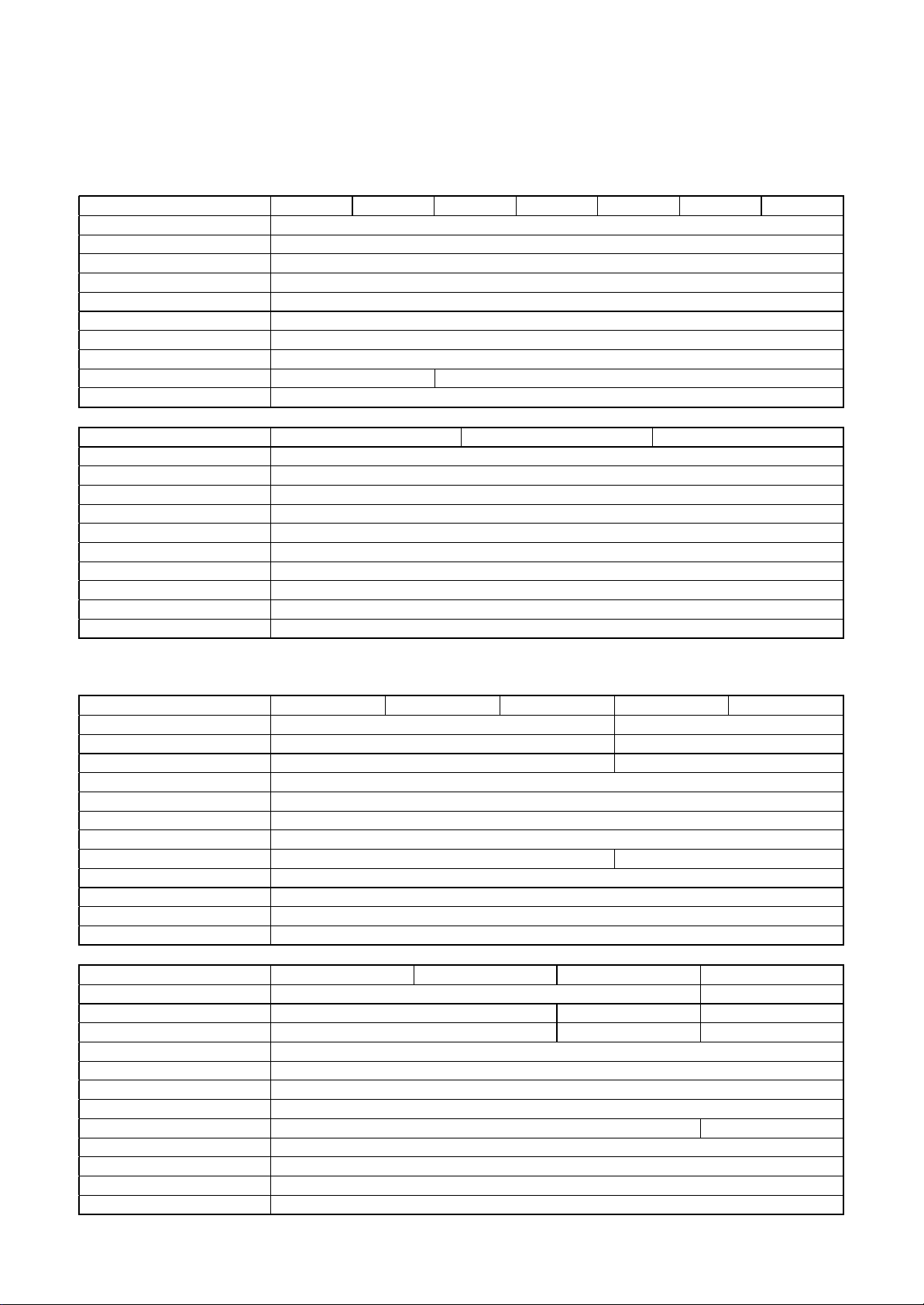
3. PARTS RATING
3-1. Indoor Unit
4-way Air Discharge Cassette Type
Model MMU-AP 0091H 0121H 0151H 0181H 0241H 0271H 0301H
Fan motor SWF-230-60-1
Drain pump motor ADP-1409
Float switch FS-0218-102
TA sensor Lead wire length : 155mm
TC1 sensor Ø4 size lead wire length : 1200mm Vinyl tube (Blue)
TC2 sensor Ø6 size lead wire length : 1200mm Vinyl tube (Black)
TCJ sensor Ø6 size lead wire length : 1200mm Vinyl tube (Red)
Pulse motor EDM-MD12TF-3
Pulse motor valve EDM-B25YGTF EDM-B40YGTF
Louver motor (panel) MP24GA
Model MMU-AP 0361H 0481H 0561H
Fan motor SWF-200-90-1
Drain pump motor ADP-1409
Float switch FS-0218-102
TA sensor Lead wire length : 155mm
TC1 sensor Ø4 size lead wire length : 1200mm Vinyl tube (Blue)
TC2 sensor Ø6 size lead wire length : 1200mm Vinyl tube (Black)
TCJ sensor Ø6 size lead wire length : 1200mm Vinyl tube (Red)
Pulse motor EDM-MD12TF-3
Pulse motor valve EDM-B60YGTF-1
Louver motor (panel) MP24GA
2-way Air Discharge Cassette Type
Model MMU-AP 0071WH 0091WH 0121WH 0151WH 0181WH
Fan motor AF-230-53-4G AF-230-39-4B
Running condenser for fan motor AC 400V, 1µF A C 450V, 2µF
Running capacitor for fan motor AC 400V, 1.0µF AC 450V, 2.0µF
Drain pump motor PJD-05230TF-1
Float switch FS-0208-608
Control P.C. board transformer TT-13
Pulse motor EDM-MD12TF-3
Pulse motor valve EDM-B25YGTF EDM-B40YGTF
TA sensor Lead wire length : 268mm
TC1 sensor Ø4 size lead wire length : 1200mm Vinyl tube (Blue)
TC2 sensor Ø6 size lead wire length : 1200mm Vinyl tube (Black)
TCJ sensor Ø6 size lead wire length : 1200mm Vinyl tube (Red)
Model MMU-AP 0241WH 0271WH 0301WH 0481WH
Fan motor AF-200-53-4F AF-200-92-4B
Running condenser for fan motor AC 450V, 2.5µF AC 450V, 3µF AC 450V, 5µF
Running capacitor for fan motor AC 450V, 2.5µF AC 450V, 3.5µF AC 500V, 5µF
Drain pump motor PJD-05230TF-1
Float switch FS-0208-608
Control P.C. board transformer TT-13
Pulse motor EDM-MD12TF-3
Pulse motor valve EDM-B40YGTF EDM-B60YGTF-1
TA sensor Lead wire length : 268mm
TC1 sensor Ø4 size lead wire length : 1200mm Vinyl tube (Blue)
TC2 sensor Ø6 size lead wire length : 1200mm Vinyl tube (Black)
TCJ sensor Ø6 size lead wire length : 1200mm Vinyl tube (Red)
26
Page 27
1-way Air Discharge Cassette (Compact type) Type
Model MMU-AP 0071YH 0091YH 0121YH
Fan motor AF-200-22-4N-1
Running capacitor for fan motor AC 400V, 1µF
Drain pump motor PJD-05230TF-1
Float switch FS-0208-602
Control P.C. board transformer TT-13
Pulse motor EDM-MD12TF-3
Pulse motor valve EDM-B25YGTF
TA sensor Lead wire length : 818mm
TC1 sensor Ø4 size lead wire length : 1200mm Vinyl tube (Blue)
TCJ sensor Ø6 size lead wire length : 1200mm Vinyl tube (Red)
Model MMU-AP 0151SH 0181SH 0241SH
Fan motor AF-200-34-4D
Running capacitor for fan motor A C 450V, 1.5µF AC 500V, 2.5µF
Drain pump motor PJD-05230TF-2
Float switch FS-0208-603
Control P.C. board transformer TT-13
Pulse motor EDM-MD12TF-3
Pulse motor valve EDM-B40YGTF
TA sensor Lead wire length : 155mm Vinyl tube
TC1 sensor Ø4 size lead wire length : 1200mm Vinyl tube (Blue)
TC2 sensor Ø6 size lead wire length : 1200mm Vinyl tube (Black)
TCJ sensor Ø6 size lead wire length : 1200mm Vinyl tube (Red)
Concealed Duct Standard Type
Model MMD-AP 0071BH 0091BH 0121BH 0151BH 0181BH
Fan motor ICF-280-120-2
Drain pump motor ADP-1409
Float switch FS-0218-102
Pulse motor EDM-MD12TF-3
Pulse motor valve EDM-B25YGTF EDM-B40YGTF
TA sensor Lead wire length : 618mm
TC1 sensor Ø4 size lead wire length : 1200mm Vinyl tube (Blue)
TC2 sensor Ø6 size lead wire length : 1200mm Vinyl tube (Black)
TCJ sensor Ø6 size lead wire length : 1200mm Vinyl tube (Red)
Model MMD-AP 0241BH 0271BH 0301BH 0361BH 0481BH 0561BH
Fan motor ICF-280-120-1 ICF-280-120-2
Drain pump motor ADP-1409
Float switch FS-0218-102
Pulse motor EDM-MD12TF-3
Pulse motor valve EDM-B40YGTF EDM-B60YGTF-1
TA sensor Lead wire length : 618mm
TC1 sensor Ø4 size lead wire length : 1200mm Vinyl tube (Blue)
TC2 sensor Ø6 size lead wire length : 1200mm Vinyl tube (Black)
TCJ sensor Ø6 size lead wire length : 1200mm Vinyl tube (Red)
27
Page 28
Concealed Duct High Static Pressure Type
Model MMD-AP 0181H 0241H 0271H 0361H 0481H
Fan motor STF-200-160-4B STF-200-160-4A STF-200-260-4C STF-200-260-4B
Running condenser for fan motor AC 500V, 4µ F AC 400V, 8µF AC 450V, 6µF AC 400V, 8µF
Drain pump motor ADP-1409
Float switch FS-0218-102-6
Pulse motor EDM-MD12TF-3
Pulse motor valve EDM-B40YGTF EDM-B60YGTF-1
TA sensor Lead wire length : 1200mm
TC1 sensor Ø4 size lead wire length : 1200mm Vinyl tube (Blue)
TC2 sensor Ø6 size lead wire length : 1200mm Vinyl tube (Black)
TCJ sensor Ø6 size lead wire length : 1200mm Vinyl tube (Red)
Under Ceiling Type
Model MMC-AP 0151H 0181H 0241H 0271H 0361H 0481H
Fan motor SWF-280-60-1 S WF-280-60-2 SWF-280-120-2
Driving motor for horizontal grille MP24GA1
Pulse motor EDM-MD12TF-3
Pulse motor valve EDM-B40YGTF EDM-B60YGTF-1
TA sensor Lead wire length : 155mm Vinyl tube
TC1 sensor Ø4 size lead wire length : 1200mm Vinyl tube (Blue)
TC2 sensor Ø6 size lead wire length : 1200mm Vinyl tube (Black)
TCJ sensor Ø6 size lead wire length : 1200mm Vinyl tube (Red)
High Wall Type
Model MMK-AP 0071H 0091H 0121H 0151H 0181H 0241H
Fan motor ICF-280-120-3
Driving motor for horizontal grille MT8-3-6
Pulse motor EDM-MD12TF-3
Pulse motor valve EDM-B25YGTF EDM-B40YGTF
TA sensor Lead wire length : 818mm Vinyl tube
TC1 sensor Ø4 size lead wire length : 1200mm Vinyl tube (Blue)
TC2 sensor Ø6 size lead wire length : 1200mm Vinyl tube (Black)
TCJ sensor Ø6 size lead wire length : 1200mm Vinyl tube (Red)
28
Page 29
Floor Standing Cabinet Type
Model MML-AP 0071H 0091H 0121H 0151H 0181H 0241H
Fan motor AF-200-19-4F AF-200-45-4F AF200-70-4K
Running condenser for fan motor AC450V, 1.2µF AC400V, 1.8µF AC450V, 2µF
Transformer TT13
Pulse motor EDM-MD12TF-3
Pulse motor valve EDM-B25YGTF EDM-B40YGTF
TA sensor Lead wire length : 818mm Vinyl tube
TC1 sensor Ø4 size lead wire length : 1200mm Vinyl tube (Blue)
TC2 sensor Ø6 size lead wire length : 1200mm Vinyl tube (Black)
TCJ sensor Ø6 size lead wire length : 1200mm Vinyl tube (Red)
Floor Standing Concealed Type
Model MML-AP 0071BH 0091BH 0121BH 0151BH 0181BH 0241BH
Fan motor AF-200-19-4G AF-200-70-4K
Running condenser for fan motor AC450V, 1.5µF AC450V, 1µF AC450V, 2µF
Transformer TT-13
Pulse motor EDM-MD12TF-3
Pulse motor valve EDM-B25YGTF EDM-B40YGTF
TA sensor Lead wire length : 818mm Vinyl tube
TC1 sensor
TC2 sensor Ø6 size lead wire length : 2000mm Vinyl tube (Black)
TCJ sensor Ø6 size lead wire length : 2000mm Vinyl tube (Red)
Ø4 size lead wire length : 2000mm Vinyl tube (Blue)
Floor Standing Type
Model MMF-AP 0151H 0181H 0241H 0271H 0361H 0481H 0561H
Fan motor AF-200-37R AF-200-63T
Running condenser for fan motor AC500V, 3µF AC500V, 3.5µF A C500V, 4µF
Transformer TT-13
Pulse motor EDM-MD12TF-3
Pulse motor valve EDM-B40YGTF EDM-B60YGTF-1
Driving motor for vertical flap MT8-3-9
AF-200-110M-1
AF-200-160H-1
TA sensor Lead wire length : 1200mm Vinyl tube
TC1 sensor
TC2 sensor Ø6 size lead wire length : 2000mm Vinyl tube (Black)
TCJ sensor Ø6 size lead wire length : 1200mm Vinyl tube (Red)
Ø4 size lead wire length : 1200mm Vinyl tube (Blue)
29
Page 30
3-2. Outdoor Unit
Model MMY-
Compressor DA421A3FB-23M Output: : 3.7 5kW × 2
4-way valve coil (Heat pump only) LB64046 AC220-240V 50Hz
Pulse motor valve coil VPV-MOAJ524C0 HAM-MD12TF-3 DC12V
2-way valve coil VPV
VPV-122DQ1 SV2, SV3C, SV3D, SV3E, SV6, SV12
2-way valve
High-pressure SW ACB-JB215 OFF : 3.73MPa, ON : 2.9MPa
Pressure sensor (For high press ure) 150XA4-H3 0. 5 to 3.5V / 0 to 0.98MPa
Pressure sensor (For low pressure) 150XA4-L1 0.5 to 4.3V / 0 to 3.73MPa
Fan motor MF-230-600-2 DC280V, 600W
Case heater AC240V, 29W × 3
Compressor ca se the rmo. US-622KXTMQO-SS OFF : 125°C, ON : 90°C × 2
VPV-303DQ1 SV3A, SV41, SV42, SV5
VPV-603DQ2 SV3B
VPV-1204DQ50 SV11
MAP0801FT8 MAP1001FT8 MAP1201FT8
AC220–240V 50Hz
SV2, SV3A, SV3B, SV3C, SV3D, SV3E
SV41, SV42, SV5, SV6, SV11, SV12
3-3. Outdoor Control Unit
Heat Recovery Model
Model MMY-
Power supply terminal block JXO-3004 AC600V / 30A, 4P
Communication line t erminal block JXO-B2H AC30V (or DC42V) / 1A, 6P
Reactor CH-44FK 1.45mH / 25A
Smoothing condenser (For compressor) 400LRSN 1500M 1500µF / 400V
Power supply transformer TT-01-03T AC230V, 350mA
P.C. board (Noise filter) MCC-1366
Line filter (AC)
P.C. board (Control board) MCC-1429
P.C. board IPDU-4T62DA1E 6.2kW MC C-1502
P.C. board (Power supply board) MCC-1439
P.C. board (IPDU for fan) IPDU-2D16DA1 800W MCC-896, MCC-897
Power complex module 6MBR25UA120 25A/1200V (MCC-1502 P.C. board)
Pipe temp. sensor (TD) —–30°C to 135°C (Ambient temp. range)
Pipe temp. sensor (TS) —–20°C to 80°C (Ambient temp. range)
Heat exchanger temp. sensor (TE ) —–20°C to 80°C (Ambient temp. range)
Outside temp. sensor (TO) —–20°C to 80°C (Ambient temp. range)
Oil temp. sensor (TK) —–30°C to 135°C (Ambient temp. range)
Liquid temp. sensor (TL) —–20°C to 80°C (Ambient temp. range)
Smoothing condenser (For fan) 400LRSN1000M 1000µF / 400V
Magnet SW FC-2S 400V / 38A
Thermistor ZPROYCE101A500 100Ω, 13A, 500V
MAP0801FT8 MAP1001FT8 MAP1201FT8
FKX-240NK-4810US 0.48mH / 30A (MCC-1366 P.C. board)
FKX-220NK-6310US 0.63mH / 25A (MCC-1366 P.C. board)
3-4. Flow Selector Unit (FS Unit)
Model RBM-Y1121FE RBM-Y1801FE
P.C. board (Control board) MCC-1431
2-way valve coil VPV AC220-240V 50Hz
2-way valve
VPV-122DQ1 SVSS, SVDD
VPV-1204DQ50 SVS, SVD
30
Page 31

TO sensor
TE sensor
3-5. Pa rts Layout in Outdoor Unit
31
SV42 valve
SV41 valve
High pressure
SW1
TD1 sensor
High pressure
SW2
TD2 sensor
Check joint
(Low pressure)
SV3D valve
SV5 valve
TS1 sensor
SV12 valve
PMV
4-way valve
Check joint
(High pressure)
High pressure sensor
Check joint
(Liquid pipe)
TS2 sensor
SV2 valve
SV11 valve
SV6 valve
SV3A valve
SV3B valve
TL sensor
Low pressure
sensor
SV3E valve
SV3C valve
TK1, TK2 sensor
TK3 sensor
TK4 sensor
Front side Rear side
Page 32

3-6. Name of Each Pa rt
Air outlet/Air outlet flap
Select air blow direction in
cooling or heating operation each.
Earth screw
It is included in the electric parts box.
Air inlet grille
Air in the room is sucked from here.
Air filter
Removes dust and trash.
(Air filter is provided in the air inlet grille.)
Air inlet
Suction duct is connected.
Air outlet
Discharge duct is connected.
Earth screw Drain pan
Earth screws are provided in the
electric parts box.
Earth screw
It is included in the electric parts box.
Air outlet/
Air outlet flap
Select air blow direction in cooling
or heating operation each.
Air inlet grille
Air in the room is sucked from here
Air filter
Remo ves dust and trash.
(Air filter is pro vided in the air inlet grille.)
Air outlet flange
Discharge duct is
connected.
Earth screw
It is included in the
electric parts box.
Air filter
Removes dust and trash.
(Air filter is provided in the air inlet grille.)
Air inlet
Air in the room is
sucked from here
Wiress remote controller
(Sold separately)
UNIT
SET
CL
SETTING
UNIT No.
CODE No.
TEST
SET DATA
R.C. No.
3-6-1. Outdoor Unit
Air inlet
They are provided at front,
rear, left, and right sides.
Fixing leg
3-6-2. Indoor Unit
[4-way Air Discharge Cassette Type]
Earth screw
It is included in the electric parts box.
32
Air outlet (Discharge)
Hot air is discharged when cooling
operation is performed.
Cold air is diacharged when heating
operation is performed.
Air outlet/Air outlet flap
Select air blow direction in cooling or heating operation each.
2-way discharge/3-way discharge
2-way discharge or 3-way discharge can be selected
according to the shape or arrangement of the room.
For details, consult with the dealer which you have
purchased the air conditioner.
Power source hole
Refrigerant pipe
connecting hole
Connecting valve is included inside here.
[1-way Air Discharge Cassette Type]
[Concealed Duct Type]
[Concealed Duct, High Static Pressure Type]
Clip
The clip is to open/close the air inlet grille.
[2-way Air Discharge Cassette Type]
Air outlet/Air outlet flap
Select air blow direction in cooling or heating operation each.
Earth screw
It is included in the electric parts box.
Center panel
Air inlet
Air in the room is sucked from here.
Air filter
Removes dust and trash.
(Air filter is provided in the air grille.)
Air inlet grille
Air in the room is sucked from here.
CODE No.
SET DATA
UNIT No.
SETTING
R.C. No.
TEST
Wiress remote controller
UNIT
CL
SET
(Sold separately)
Air filter
Removes dust and trash.
(Air filter is provided in the center panel.)
Page 33

SETTING
UNIT No.
CODE No.
TEST
SET DATA
R.C. No.
2
9
10
11
17
16
12
14
13
15
5
6
7
3
1
8
4
33
[Under Ceiling Type] [Floor Standing Cabinet Type]
Air inlet port
The air in the room is sucked
in from this port.
Button
Button to open/close
the suction port
Air filter
Removes dust or trash.
(Provided on the suction port.)
Air outlet/Air outlet flap
Change the direction of the air to
be discharged according to
cool/heat mode.
Earth screw
Earth screws are
provided in the
electric parts box.
Air filter
Removes dirt or dust.
(It is included in the suction port.)
Air outlet/Air outlet flap
Exchanges the air direction
according to cooling or
heating time.
[Floor Standing Concealed Type]
[High Wall T ype]
Air inlet grille
Air in the room is
sucked from here.
Air filter
Removes dust and trash.
(Air filter is provided in
the air inlet grille.)
Earth screw
Earth screws are provided
in the electric parts box.
Air outlet/Air outlet flap
Change the direction of the
air to be discharged according
to cool/heat mode.
Air outlet port
Earth screw
It is prepared
in the electric
parts box.
Air inlet port
Sucks air inside of
the room from here.
Front panel (Lower side)
Drain pan (With drain filter)
This accessory is installed
at the local site.
Air filter
Removes dirt or dust.
(It is included in the suction port.)
[Floor Standing Type]
Horizontal flap/
Air outlet port
Exchanges the air
SET DATA
SETTING
CODE No.
UNIT No.
R.C. No.
TEST
Wiress remote controller
UNIT
CL
SET
(Sold separately)
direction according to
cooling or heating time.
Air inlet port
Sucks air inside of
the room from here.
Air filter
Removes dirt
or dust.
Earth screw
It is prepared in the
electric parts box.
Drain pan
Water accumulated
in the drain pan is
drained from here
through the drain pipe.
Earth screw
It is prepared
in the electric
parts box.
Air inlet port
Sucks air inside of
the room from here.
Fixing metal holder
Vertical flap
The air can be
automatically
discharged
rightward/leftward
at stated periods.
Fixing metal holder
(Right and left)
3-7. Parts Name of Remote Controller
Operation section
• Using a remote controller, maximum 8 indoor units can be operated.
• After the operation contents have been once set up, the remote
controller can be operated by pushing ON/OFF buttons only.
Display section
In the display example, all indicators are displayed for the explanation.
In reality only, the selected contents are indicated.
• When turning on the leak breaker at the first time, [SET DATA] flashes on the display part of the remote controller.
While this display is flashing, the model is being automatically confirmed. Accordingly, wait for a while after [SET
DAT A] display has disappeared, and then use the remote controller.
1
SET DATA display
Displayed during setup of the timer.
2
Operation mode select display
The selected operation mode is displayed.
3
CHECK display
Displayed while the protective device works or a
trouble occurs.
4
Timer time display
Time of the timer is displayed. (When a trouble
occurs, the check code is displayed.)
5
Timer SETIN setup display
When pushing the Timer SETIN button, the
display of the timer is selected in order of
[OFF]
[ON]
6
Filter display
If “FIL TER ” is displayed, clean the air filter.
7
TEST run display
Displayed during a test run.
8
Flap position display
Displays flap position.
9
SWING display
Displayed during up/down movement of the flap.
10
11
→ [OFF] repeat OFF timer →
→ No display.
Set up temperature display
The selected set up temp. is displayed.
Remote controller sensor display
Displayed while the sensor of the remote
controller is used.
12
PRE-HEAT display
Displayed when the heating operation starts or
defrost operation is carried out.
While this indication is displayed, the indoor fan
stops or the mode enters in LOW.
13
Operation ready display
Displayed when cooling operation is unavailable
because heating operation is performed.
14
No function display
Displayed if there is no function even if the button is
pushed.
15
Air volume select display
The selected air volume mode is displayed.
(AUTO)
(MED.) (LOW)
In the Concealed Duct High Static Pressure type
models, [HIGH] only is displayed for the air speed.
16
Mode select control display
Displayed when pushing “Operation mode select”
button while the operation mode is fixed to heating or
cooling by the system manager of the air conditioner.
17
Central control display
Displayed when using the remote controller together
with the central control remote controller, etc.
If Remote controller is prohibited at the centralcontrol
side,
flashes when operating
the change is not accepted.
(The contents available to be set up on the remote
controller differ according to the central control mode.
For details, refer to Owner’s Manual of the central
control remote controller.)
, , / buttons and
SET DATA
SETTING
SET
(HIGH)
CODE No.
UNIT No.
R.C. No.
TEST
UNIT
CL
Display
section
Operation
section
Page 34

UNIT
1
2
4
3
SET
CL
HEAT DRYAUTO COOL FAN
(Dehumidity)
LOW MED. HIGH
AUTO
Operation section
Push each button to select a desired operation.
• The details of the operation needs to be set up once, afterward, the air conditioner can be used by pushing
2
4
1
34
Air volume select button
Selects the desired air volume mode.
2
Timer set button
TIMER SET button is used when the timer is set
up.
3
Check button
The CHECK button is used for the chec k operation. During normal operation, do not use this
button.
4
Fan button
F AN button is used when a fan which is sold on
the market or etc. is connected.
• If “No function” is displayed on the remote
controller when pushing the FAN button, a fan
is not connected.
5
Filter reset button
Resets (Erases) “FILTER ” display.
6
UNIT and AUTO flap button
UNIT
7
Operation lamp
Lamp is lit during the operation. Lamp is off
when stopped.
Although it flashes when operating the protection
device or abnormal time.
button only.
3
5
Select a unit No.
Swing automatically or manually
SET
1
7
9
UNIT
CL
6
8
When the button is pushed, the operation
starts, and it stops by pushing the button
again.
When the operation has stopped, the operation lamp and all the displays disappear.
9
Operation select button
Selects desired operation mode.
10
Set up temperature button
Adjusts the room temperature.
Set the desired set temperature by pushing
OPTION :
Remote controller sensor
Usually the TEMP. sensor of the indoor unit senses
the temperature. The temperature on the surrounding of the remote controller can also be sensed.
For details, contact the dealer from which you have
purchased the air conditioner.
button
or .
8
10
3-8. Correct Usage
When you use the air conditioner for the first time or when you change the SET DATA value, follow the procedure
below. From the next time, the operation displayed on the remote controller will start by pushing the
Preparation
Turn on the main power switch and/or the leakage breaker.
• When the power supply is turned on, a partition line is displayed on the display part of the remote controller.
* After the power supply is turned on, the remote controller does not accept an operation for approx. 1 minute, but it
1
2
3
4
Stop
Push button.
The operation lamp goes off, and the operation stops.
button only.
is not a failure.
REQUIREMENT
• While using the air conditioner, operate it only with button without turning off the main power
switch and the leak breaker.
Push button.
The operation lamp goes on, and the operation starts.
Select an operation mode with the “MODE” button.
One push of the button, and the display
changes in the order shown on the right.
• In HEAT
air flow becomes LOW and the air volume decreases.
• In the defrost mode, the fan stops so that cool air is not discharged and PRE-DEF
•“Dry” function is not provided to Concealed Duct high Static Pressure type.
Select air volume with “FAN ” button.
One push of the button, and the display
changes in the order shown on the right.
• When air volume is “AUTO
temperature and room temperature.
• In DRY
• In heating operation, if the room temperature is not heated sufficiently with VOLUME “LOW
select “MED. ” or “HIGH ” operation.
• The temperature which the temperature sensor detects is one near the air inlet of the indoor unit. Therefore it slightly differs from the room temperature according to the installation status. The setup value is a
criterion of the room temperature. (Automatic air speed cannot be selected in FAN mode.)
• Air volume of function is not provided to “Concealed Duct High Static Pressure Type” but air speed “HIGH
Determine the set up temperature by pushing the “TEMP. ” or “TEMP. ” button.
mode, if the room temperature reaches to the set temperature, the outdoor unit stops and the
is displayed.
”, air volume differs according to the temperature difference between set
mode, “AUTO ” is displayed and the air volume is LOW.
” operation,
” only is displayed.
Page 35

UNIT
4
1
SET
CL
3
2
3-9. Automatic Operation (A uto Changeo ver)
When you set the air conditioner in mode or switch over from AUTO operation because of some settings
change, it will automatically select either cooling, heating, or fan only operation depending on the indoor temperature.
Start
1
35
Push this button to start the air conditioner.
2
Mode select button (MODE)
Select Auto.
3
Temperature button
Set the desired temperature.
• In case of cooling, start the operation after approx. 1 minute.
• In case of heating, the operation mode is selected in accordance with the room temperature and operation
• When you select the Auto mode, it is unnecessary to set the f an speed. The FAN speed display will show
• After the heating operation has stopped, FAN operation may continue for approx. 30 seconds.
• When the room temperature reaches the set temperature and the outdoor unit stops, the super low wind is
• If the Auto mode is uncomfortable, you can select the desired conditions manually.
When restarting the operation after stop
• When restarting the operation immediately after stop, the air conditioner does not operate for approx. 3
minutes to protect the machine.
Stop
Push button.
Push this button again to stop the air conditioner.
button
starts after approximately 3 to 5 minutes.
AUTO and the fan speed will be automatically controlled.
discharged and the air volume decreases excessively. During defrost operation, the fan stops so that cool
air is not discharged and “PRE-HEAT
” is displayed.
NOTE
3-10. TIMER Operation
A type of timer operation can be selected from the following three types.
OFF timer : The operation stops when the time of timer has reached the set time.
Repeat OFF timer : Every time, the operation stops after the set time has passed.
ON timer : The operation starts when the time of timer has reached the set time.
Timer operation
1
Push TIMER SET button.
• The timer display (type) changes for every
push of the button.
• SET DATA and
2
Push to select “SET TIME”.
For every push of button, the set time increases in the unit of 0.5 hr (30 minutes).
The maximum set time is 72.0 hr.
For every push of
The minimum set time is 0.5 hr.
3
Push SET button.
• SET DATA display disappears and display goes on.
(When ON timer is activated, time is displayed, and after time of the timer has been up, displays other
than ON disappear.)
display flashes.
button, the set time decreases in the unit of 0.5 hr (30 minutes).
Cancel of timer operation
4
Push CL button.
• TIMER display disappears.
NOTICE
• When the operation stops after the timer reached the preset time, the Repeat OFF timer resumes the
operation by pushing button and stops the operation after the time of the timer has reached the
set time.
OFF
(OFF timer) (Repeat OFF timer)
OFF ON
No display
(ON timer)
Page 36

3-11. Re-Installation
DANGER
Ask the dealer or an installation professional to re-install the air conditioner to a new place
or move it to another place and to observe the following items.
If the air conditioner is inappropriately by installed by yourself, it may cause electric shock
or fire.
Do not install the air conditioner in the following places
• Do not install the air conditioner in any place within 1 m from a T V, stereo, or radio set. If the unit is installed in
such place, noise transmitted from the air conditioner affects the operation of these appliances.
• Do not install the air conditioner near a high frequency appliance (sewing machine or massager for business
use, etc.), otherwise the air conditioner may malfunction.
• Do not install the air conditioner in a humid or oily place, or in a place where steam, soot, or corrosive gas is
generated.
• Do not install the air conditioner in a salty place such as seaside area.
• Do not install the air conditioner in a place where a great deal of machine oil is used.
• Do not install the air conditioner in a place where it is usually exposed to strong wind such as in seaside area
or on the roof or upper floor of a building.
• Do not install the air conditioner in a place where sulfureous gas generated such as in a spa.
• Do not install the air conditioner in a vessel or mobile crane. Be careful with noise or vibrations
• Do not install the air conditioner in a place where noise by outdoor unit or hot air from its air outlet annoys
your neighbors.
• Install the air conditioner on a solid and stable foundation so that it prevents transmission of resonating,
36
operation noise and vibration.
• If one indoor unit is operating, some sound may be audible from other indoor units that are not operating.
3-12. Tr oub les and Causes
CAUTION
If any of the following conditions occur, turn off the main power supply switch and immediately contact the
dealer :
• The operation lamps flash at short intervals (5 Hz) even though you have tried turning off the power
supply and turning on again after 2 or 3 minutes.
• Switch operation does not work properly.
• The main power fuse often blows out, or the circuit breaker is often activated.
• A foreign matter or water fall inside the air conditioner.
• Any other unusual conditions are observed.
3-13. Information
Confirmation before operation
• Turn on the power switch 12 hours before starting the
operation.
• Check whether earth wire is cut off or disconnected.
• Check the air filter is connected to the indoor unit.
Heating capacity
• A heat pump system which absorbs heat from
outside of the room and then discharges heat into the
room is adopted for heating. If the outside temperature falls, the heating capacity decreases.
• When the outside temperature is too low, it is recommended to use this air conditioner together with other
heating equipment.
Defrost during heating operation
• In heating operation, if there is frost on the outdoor
unit, the operation changes automatically to the
defrost operation (Approx. 2 to 10 minutes) to
increase the heating efficiency.
• During defrost operation, the fan of the indoor unit
stops.
3-minutes protection
• When restarting the operation just after the operation
has been stopped or the main power switch has
turned on, the outdoor unit does not work for approx.
3 minutes in order to protect the air conditioner.
Power failure
• If a power failure occurred during operation, all
operations stop.
• When the power is returned after a power failure, the
operation lamp notifies the power-ON by flashing
operation lamp on the remote controller.
• When restarting the operation, push
button again.
Fan rotation in stopped unit
• In heating operation even in the stopped indoor unit,
the fan rotates once for several minutes per approx.
an hour when the other indoor unit is operating to
protect the air conditioner.
Protective device (High pressure switch)
This device stops automatically an operation when
excessive force is applied on the air conditioner.
If the protective device works, the operation stops and
the operation lamp flashes.
When the protective device works, the indication
and the check code are displayed on the display
section of the remote controller. In the following cases,
the protective device may work.
In cooling operation
• The suction port or discharge port of the outdoor unit
is closed.
• A strong wind continuously blows to the discharge
port of the outdoor unit.
In heating operation
• Dust or waste adheres excessively to air filter of the
indoor unit.
• The discharge port of the indoor unit is closed.
If the protective device works, turn off the main
power switch, solve the cause, and then start the
operation again.
Cooling/Heating operation of Multi
system air conditioner
<Standard type>
• Although each indoor unit can be individually controlled in the Multi system air conditioner, the cooling
operation and the heating operation cannot be
simultaneously performed in the multiple indoor units
which are connected to an outdoor unit. If doing so,
the indoor unit in cooling mode stops and “
operation part goes on. The indoor unit in heating
mode continues operation. When the operation mode
has been fixed to cooling or heating by the system
manager of the air conditioner, an operation other
than the setup mode cannot be performed.
If an operation other than the setup mode is performed, “
operation stops.
” at operation part goes on and the
” at
<Simultaneous operation type>
• When the outdoor temperature goes out of the
operable range, cooling or heating operation may not
be performed in order to protect the equipment. In
this case, “
” goes on.
Characteristics of heating operation
• The wind is not out just after starting an operation.
The hot wind starts to blow 3 to 5 minutes after (Time
differs according to indoor/outdoor temperature.) the
indoor heat exchanger has warmed up.
• During operation, the outdoor unit may stop if the
outside temperature rises.
Characteristics of cooling/heating simultaneous operation
• If the outdoor temperature drops during operation,
the fan of the outdoor unit may stop.
Page 37

3-14. Adjustment of Air Direction
UNIT
UNIT
3
1, 2
SET
CL
No
display
Unit No.
1-1
Unit No.
1-2
Unit No.
1-3
Unit No.
1-4
T o increase the cooling/heating efficiency,
be sure to make proper use of the discharge
flap for cooling or heating operation.
As the characteristics of air, cool air collects at
lower levels, and hot air collects at higher levels.
Set the flap so that air blows out horizontally.
If cooling operation is performed with the flap blowing air
downwards, the air outlet or surface of the flap will be
wet with dew, and dewdrop may fall down.
[4-way Air Discharge Cassette Type]
In cooling operation
• Use the discharge
flap with horizontal
set point.
• When the air conditioner stops, the flap (adjustment plate of up/down air direction) directs downward automatically.
• When the heating operation is in “PRE-HEAT
directs upward. The swinging starts after “PRE-HEAT
remote controller even if the heating operation is in “PRE-HEAT
How to set up the air direction
1
Push during operation.
The air direction changes for ev ery push of the button.
In HEAT operation
Direct the flap (adjustment plate of up/down air
37
direction) downward. If directing at upward, hot
air may not come to the foot.
In heating operation
• Use the discharge
flap with downward
set point.
” states, the flap (adjustment plate of up/down wind direction)
” status cleared, SWING is displayed on the
Initial setup
CAUTION
” status.
SET
2-way/3-way air discharge
2-way discharge or 3-way discharge can be selected according to the shape or arrangement of the room.
For details, consult with the dealer which you have purchased the air conditioner.
NOTES
• If cooling operation is executed under condition of downward blowing, the cabinet or surface of the horizontal flap gets wet with dew and may drop .
• During heating operation under condition of horizontal blowing, unevenness of temperature may increase
in the room.
• Never handle the horizontal flap directly with hands, otherwise a trouble is caused. Use the flap operation
switch on the remote controller to change direction of the horizontal flap. The hori zontal flap does not stop
even if pushing the horizontal flap. Adjusting the stop position, push the switch.
[2-way Air Discharge Cassette Type]
In cooling operation
Use the air outlet flap with horizontal set point.
UNIT
CL
Setup of air direction and swinging
Heating operation
Use the air outlet flap with downward set point.
How to start swing
2
How to stop swing
3
4 Auto flap button
In COOL/DRY operation
Direct the flap (adjustment plate of up/down air
direction) upward. If directing it downward, the
dew may from on the surface of the air discharge port and may drop down.
Initial setup
1, 2, 3 4
In FAN operation
Initial setup
In all modes
Series of
operation
Push , set the flap (adjustment plate of up/down
air direction) direction to the lowest position, and then
push
SWING is displayed and the up/down wind direction is
automatically selected.
again.
Display when stopping the swing
Fan/Heat
operation
Cool/Dry
operation
Push SWING/WIND again while the flap is swing.
• The flap stops at a position when you push. After then, if pushing , the air direction descends from
the highest position.
• In COOL/DRY operation, the flap does not stop as it directs downward. If stopping the flap as it directs
downward during swing operation, it stops after moving to the 3
UNIT
• Push
Then the indoor unit No. in a group control is displa yed.
For the displayed indoor unit, set up the air direction.
• If the unit No. is not displayed, all the indoor units are operated at the same time.
• Every pushing
to set up the air direction individually in each indoor unit.
UNIT
, the display is exchanged as follows:
UNIT
rd
position from the highest position.
No
Unit No.
1-4
Unit No.
display
1-1
Unit No.
1-3
Unit No.
1-2
1
Push during operation.
• is displayed and the air direction is automatically exchanged upward/downward.
When a remote controller operates the multiple
indoor units, an indoor unit is selected and air
direction can be individually set up.
2
Push again during swinging of the
flap.
• You can stop the flap at the desired position.
3
Auto flap button
• Push
individually in each indoor unit. Then the indoor
unit No. in a group control is displayed. For the
displayed indoor unit, set up the air direction.
• If the unit No. is not displayed, all the indoor
units are operated at the same time.
• Every pushing
changed as follows:
UNIT
to set up the air direction
, the display is ex-
UNIT
Page 38

[1-way Air Discharge Cassette Compact Type]
1
2
In this case, do not use the
swing function.
<Up/Down air direction adjustment>
[High Wall T ype]
<Up/Down air direction adjustment>
In cooling operation
In cooling operation, use the air outlet flap with
horizontal set point so that cool air diffuses the whole
room.
In heating operation
In heating operation, use the air outlet flap with
downward set point so that the hot air is spread to
the floor.
<Left/Right air direction adjustment>
When you change the blowout direction to left/right,
direct the vertical grille inside of the air outlet flap to
desired direction.
<Setup of air direction and swing>
Refer to that of 2-way Air Discharge Cassette Type.
[Under Ceiling Type]
<Up/Down air direction adjustment>
38
In cooling operation
In cooling operation, use the air outlet flap with
horizontal set point so that cool air diffuses the whole
room.
In heating operation
In heating operation, use the air outlet flap with
downward set point so that the hot air is spread to
the floor.
<Left/Right air direction adjustment>
When you change the blowout direction to left/right,
direct the vertical flap inside of the air outlet flap to
desired direction.
[Concealed Duct Standard Type]
When using a air outlet port unit (sold separately), adjust the air direction as follows:
In cooling operation
In cooling operation, use the air outlet flap with
horizontal set point so that cool air diffuses the whole
room.
In heating operation
In heating operation, use the air outlet flap with
downward set point so that the hot air is spread at
the foot.
In cooling operation
In cooling operation, use the air outlet flap with
horizontal set point so that cool air diffuses the whole
room.
In heating operation
In heating operation, use the air outlet flap with
downward set point so that the hot air is spread to
the floor.
<Left/Right air direction adjustment>
When you change the blowout direction to left/right,
direct the vertical flap inside of the air outlet flap to
desired direction.
[Floor Standing Cabinet Type]
In cooling operation
In cooling operation, use the air outlet flap with
horizontal set point so that the cold air diffuses in
whole room.
In heating operation (For Heat-pump model only)
In heating operation, use the air outlet flap with
downward set point so that the hot air blows at the
foot.
[Floor Standing Type]
<Adjustment of air direction upward/downward>
In cooling operation
In cooling operation, move the flap with hands and use it with horizontal
air outlet point so that the cold air diffuses in whole room.
In heating operation (For Heat-pump model only)
In heating operation, move the flap with hands and use the air outlet flap
with downward set point so that the hot air blows at the foot.
<Adjustment of air direction rightward/leftward>
Lift up the vertical flap lightly, direct it toward the desired
direction, and lower it.
In this case, do not use the Swing function.
Page 39

CODE No.
1,
2
Suction grille
Button
3-15. Air Conditioner Operations and Performance
3 minutes protection function
3-minutes protection function prevents the air conditioner from starting for initial 3 minutes after the main power
switch/circuit breaker is turned on for re-starting the air conditioner.
Power failure
Power failure during operation will stop the unit completely.
• To restart the operation, push the START/STOP button on the remote controller.
• Lightning or a wireless car telephone operating nearby may cause the unit to malfunction. Turn off the main power
switch or circuit breaker and then turn them on again. Push the START/STOP button on the remote controller to restart.
Heating characteristics
Preheating operation
The air conditioner will not deliver warm air immediately after it is turned on. Warm air will start to flow out after
approximately 5 minutes when the indoor heat exchanger warmed up.
Warm air control (In heating operation)
When the room temperature reaches the set temperature, the fan speed is automatically reduced to prevent to blow
cold draft. At this time, the outdoor unit will stop.
Defrosting operation
If the outdoor unit is frosted during the heating operation, defrosting starts automatically (for approximately
2 to 10 minutes) to maintain the heating capacity.
• The fans in both indoor and outdoor units will stop during the defrosting operation.
• During the defrosting operation, the defrosted water will be drained from the bottom plate of the outdoor unit.
Heating capacity
In the heating operation, the heat is absorbed from the outside and brought into the room. This way of heating is
called heat pump system. When the outside temperature is too low, it is recommended to use another heating
apparatus in combination with the air conditioner.
39
Attention to snowfall and freeze on the outdoor unit
• In snowy areas, the air inlet and air outlet of the outdoor unit are often covered with snow or frozen up.
If snow or freeze on the outdoor unit is left as it is, it may cause machine failure or poor warming.
• In cold areas, pay attention to the drain hose so that it perfectly drains water without water remaining inside for
freeze prevention. If water freezes in the drain hose or inside the outdoor unit, it may cause machine failure or
poor warming.
Air conditioner operating conditions
For proper performance, operate the air conditioner under the following temperature conditions:
Cooling operation
Heating operation
If air conditioner is used outside of the above conditions, safety protection may work.
* Do not use “Super HRM” for other than personal usage where the ambient temperature may go down below –5°C.
(For example, OA equipment/Electric device/Food/Animals and plants/Art object)
When outdoor temperature goes out of specified range, “ or ” mark is indicated on the Wired remote
controller display and required operation will stop.
& ” : When heating operation. “ ” : When cooling operation.
“
Notice :
• This indication is not failure.
• When outdoor temperature goes back to specified range, “
• Operation stops because concurrent operation can not be kept in the condition of out of specification for Super
HRM. (Outdoor temp. (DB) < –5°C : Cooling, > 21°C : Heating)
Outdoor temperature : –5°C to 43°C (Dry-bulb temp.)
Room temperature : 21°C to 32°C (Dry-bulb temp.), 15°C to 24°C (Wet-bulb temp.)
CAUTION
Outdoor temperature : –15°C to 15°C (Wet-bulb temp.)
Room temperature : 15°C to 28°C (Dry-bulb temp.)
Room relative humidity – less than 80 %. If the air conditioner operates
in excess of this figure, the surface of the air conditioner may cause dewing.
CAUTION
or ” disappear and star t nor mal operation.
3-16. Maintenance
For maintenance, be sure to turn off the main power switch.
WARNING
• Please do not intend to do the daily
maintenannce and/or Air Filter cleaning by
yourself.
Otherwise, you may contact with revolving fan or
active electrity when you insert your hands into the
unit during running of the air conditioners.
Do not handle the buttons with wet
hands; otherwise an electric shock
may be caused.
<Daily maintenance>
Cleaning of air filter
1
If is displayed on the remote controller,
maintain the air filter.
2
Clogging of the air filter decreases cooling/
heating efficiency.
• After cleaning, push button. display disap-
pears.
[4-way Air Discharge Cassette Type]
• When using an elevator panel, move down the suction port with the elevator remote controller.
1
Open the suction port.
• Slide the clip of the suction port to inside and
open the suction port slowly while holding it.
2
Take out the air filter.
• Push the extrusion of the air filter to inside and
pull out it to take out the air filter.
3
Cleaning with water or vacuum cleaner
• If dirt is heavy, clean the air filter by tepid water
with neutral detergent or water.
• After cleaning with water, dry the air filter
sufficiently in a shade place.
4
Mount the air filter.
5
Close the suction port.
• Close the suction port, slide the clip outward,
and then fix it surely.
6
Push .
• display disappears.
Cleaning of oil guard filter
• Clean the oil guard filter once per 2 weeks.
• Clean the oil guard filter by tepid water with neutral
detergent or water.
• After cleaning with water, rinse and dry the oil guard
filter sufficiently in a shade place.
1
Information
• The oil guard filter does not surely collect oil soot
though it has an excellent endurance against oil
soot.
• The cleaning interval for the oil guard filter is
calculated under environmental condition of oil soot
density 3.5mg/m
Adjust cleaning interval according to conditions of
adhered oil soot or dirt.
3
3
.
CAUTION
Strap to
prevent falling
Air filter
Suction grille
2
Push
5
Button
Page 40

Cleaning of discharge louver
Pull out filter downward
while holding the frames.
Inlet grille knob
Air filter
Inlet grille
Pull out inlet grille
while pushing hook.
Inlet grille
Inlet grille
fixing knob
Hinge
Slide
The air outlet flap can be removed to clean if necessary.
1
Remove the air outlet flap.
• Holding the both ends of the air outlet flap,
remove it with sagging the center downward.
2
Clean the air outlet flap with water.
• If dirt is heavy , clean the air outlet flap by tepid
water with neutral detergent or water.
3
Mount the air outlet flap.
• First push in the one side, and insert the
opposite side with sagging the center downward.
Be careful to direction when mounting
the louver.
Set the surface with printed mark upward, and
mount the flap so that the arrow mark of the
printed mark directs outward.
[2-way Air Discharge Cassette Type]
• Hold the center panel and pull it toward you and
40
pull down it slowly downward. (The center panel
can move either leftward or rightward. Remove it
after confirmation.)
• Take off the fall-preventing straps at the both sides.
• Pull down the air filter to take out it.
For AP0631, AP0481, and AP0561 types, hold
[ ]
the claw of the air filter and pull down it.
1
2
2
Insert in the flap sagging
1
3
Insert
[1-way Air Discharge Cassette Compact Type]
1. Push [PUSH] at the center and left/right of the
suction port to open the suction port.
2. Take out the air filter by lifting up it once and then
pull it downward.
REQUIREMENT
• Insert the air filter of 1-way Air Discharge Cassette
Compact Type surely into the specified position.
down the center downward.
[Concealed Duct Standard Type]
• Slide [Click] of the suction panel toward arrow direction and then open the panel downward. Turn the lever at
the bottom side of the main unit to take out the air filter.
Clamp
Stepped screw
[Concealed Duct High Static Pressure Type]
• Cleaning method differs according to the mounted air filter type.
For cleaning method, please contact the dealer .
• The cleaning method differs depending on the type of attached air filter .
Please ask the constructor or the dealer which you purchased the air conditioner.
<Before cooling season>
Cleaning of drain pan
• For cleaning of the drain pan, contact the dealer . (If the drain pan or drain port is clogged with dust, water
is disabled to drain. In some cases, water overflows from the drain pan and it may wet wall or floor.
Be sure to clean the drain pan before the cooling season.)
[Under Ceiling Type]
1
Open the suction grille.
• Hold “knob” of the inlet grille, push it rearward (OPEN),
and then open the inlet grille quietly while holding it.
2
Take out the air filter.
• Push knobs of the air filter to remove the claws of the
inlet grille. Remove the air filter by pulling it toward you.
3
Suck dust by a vacuum cleaner or clean with water.
• When dirt is heavy , it is effective to clean the filter with
tepid water with dissolved neutral detergent or cold water.
• After cleaning the filter with water,
dry the filter completely in the shade.
4
Mount the air filter.
5
Close the inlet grille.
• Close the inlet grille, slide the “knob”
toward you, and then fix it surely.
6
Push .
• display disappears.
CAUTION
After cleaning, be sure to attach the fall-preventing straps of the center panel; otherwise an injury is caused
by falling.
Inlet grille knob
Air filter
Inlet grille
Page 41

[High Wall Type]
/
Air outlet Drain receiver (With strainer)
Air filter
Removes dirt or dust.
(It is included in the inlet grille.)
Front panel
(Lower side)
Air outlet / Air outlet flap
Air filter
Removes dirt or dust.
(It is included in the inlet grille.)
Air inlet glille
I will wipe soft
and dry cloth!
Do not use.
Polishing
powder
Benzene
Thinner
Chemical
floor-cloth
Use after drying
when it has not been
used for a long time!
<Air inlet grille>
Wipe it with a dried soft cloth.
• If dirt of the main unit is not cleaned even if wiped with
a dried soft cloth, wipe it completely squeezed cloth
which was rinsed with tepid water below 40°C.
Air inlet grille
Air in the room is sucked from here.
[Floor Standing Cabinet Type]
Cleaning of the main unit/remote controller
• Wipe them with soft and dry cloth.
• If heavy dirt adheres to the main unit, wipe out it
with a cloth dampened with tepid water. For the
remote controller, use a dry cloth.
<Air outlet grille/Air outlet flap>
• If using a metal brush or hard sponge for maintenance of the front panel, the surface is scratched and
coating of the front panel may be pealed.
• Use neutral detergent for kitchen to clean a heavy dirt
and then rinse the grille or flap with water.
Suck dust by a vacuum cleaner or clean with water.
• After cleaning the filter with water, dry the filter completely
in the shade.
[Floor Standing type]
41
Cleaning of drain pan
• For cleaning of the drain pan, contact the dealer . (If the drain pan or drain port is clogged with dust, water
is disabled to drain. In some cases, water overflo ws from the drain pan and it may wet wall or floor.
Be sure to clean the drain pan before the cooling season.)
<Attachment/detachment of the air filter>
• Pull the air filter downward and take out tow ard you.
• Insert the air filter into the indoor unit and push in it.
Air outlet grille
Air filter
Removes dust and trash.
(Air filter is provided in the air inlet grille.)
Air outlet flap
Attachment air filter
• Before you clean the air conditioner, be sure to turn
off the circuit breaker or the main power switch.
• Clean the air filter every two weeks. If the air filter is
clogged with dust, the performance of the air
conditioner will deteriorate.
[Floor Standing Concealed Type]
• Do not use benzene, thinner, polishing powder, or
similar solvents for cleaning. These may cause a
crack or deformation.
<If you do not use the unit for more than
1 month>
• Operate the fan for half a day to dry inside of the
main unit sufficiently.
• Turn off the main power switch.
• Clean the air filter and then remount it as before.
Suck dust by a vacuum cleaner or clean with water.
• When dirt is heavy, it is effective to clean the filter with
tepid water with dissolved neutral detergent or cold water.
• After cleaning the filter with water, dry the filter completely
in the shade.
• Clean the drain pan or the drain receiver. If the drain
pan or the drain receiver is clogged with dust, water
may overflow causing getting wet on the floor.
<How to remove front panel>
• Push down hook of the air filter on the front panel
(Lower side)
• Pull the air filter toward you to remove it.
• This model is a concealed type. Therefore conceal
other parts than the air outlet and the air filter.
Be sure not to touch the electric parts box, the
surrounding lead wires, the refrigerant pipes, etc.
directly with the hands.
<Before cooling season (Concealed Duct
High Static Pressure Type)>
Cleaning of drain pan and drain receiver
(With strainer)
CAUTION
Clean the drain pan and the drain receiver
(strainer)
If the drain pan or the drain receiver chokes with
dust, water overflows or ceiling or floor gets wet.
REQUIREMENT
For cleaning of the drain pan or drain receiver, contact
the dealer which you purchased the air conditioner.
Page 42

3-17. How to Use the Air Conditioner Efficiently
To save the charges for electricity and to gain comfortable cooling/heating operation
3-18. When the Following Symptoms are Found
Check the points described below before asking repair servicing.
Clean the air filter frequently
• If the air filter is clogged, cooling/heating efficiency
decreases.
Do not cool/heat the room excessively
WARNING
Do not expose your body in cool air for a
long time; otherwise it causes worse
condition or health loss.
• It is unhealthy; especially take care of children or
42
aged persons.
• Recommended set temperature
Cool
26 to 28°C
Heat
22 to 24°C
Don’t forget
periodical
check!
Don’t cool
excessively!
Close window or door often
• Close window or door often so that cool/hot air
does not out of the room.
Close windows
and doors often!
Evenness of room temperature
• Using a discharge louver, adjust air direction.
Exposing yourself for a long time in blowing air
exerts a bad influence upon your health.
Symptom
Outdoor unit • White misty cold air
Indoor unit •“Swish” sound is
or water is out.
• Sometimes, noise
“Pushu !” is heard.
heard sometimes.
• Slight “Pishi!” sound
is heard.
• Discharge air smells.
•“
” indication is lit.
Check again.
• Sound or cool air is
output from the
stand by indoor unit.
• When power of the
air conditioner is
turned on, “Ticktock”
sound is heard.
Operates or stops automatically.
Does not operate.
Silent
Air is not cooled or warmed sufficiently.
It is not a failure.
It’s strange.
Cause
• Fan of the outdoor unit stops automatically and performs defrost
operation.
• Solenoid valve works when defrost operation starts or finishes.
• When the operation has started, during the operation, or immediately
after the operation has stopped, a sound such as water flows may be
heard, and the operation sound may become larger for 2 or 3 minutes
immediately after the operation has started. They are flowing sound of
refrigerant or draining sound of dehumidifier.
• This is sound generated when heat exchanger, etc. expand and
contract slightly due to change of temperature.
• Various smell such as one of wall, carpet, clothes, cigarette, or
cosmetics adhere to the air conditioner.
• Do not the outdoor temperature go out of the specified range?
• When the manager of the air conditioner has fixed the operation to
COOL or HEAT, and an operation contrary to the setup operation is
performed.
• When fan operation stopped to prevent discharge of hot air.
• Since refrigerant is flowed temporarily to prevent stay of oil or
refrigerant in the stand by indoor unit, sound of flowing refrigerant,
“Kyururu” or “Shaa” may be heard or white steam when other indoor
unit operates in HEAT mode, and cold air in COOL mode may be
blow-out.
• Sound is generated when the expansion valve operates when power
has been turned on.
• Is the timer “ON” or “OFF”?
• Is it a power failure?
• Is the power switch turned off?
• Is the power fuse or breaker blown?
• Has the protective device operated? (The operation lamp goes on.)
• Is the timer “ON”? (The operation lamp goes on.)
• Do not the outdoor temperature go out of the specified range?
• Is the suction port or discharge por t of the outdoor unit obstr ucted?
• Are any door or window open?
• Is the air filter clogged with dust?
• Is discharge louver of the indoor unit set at appropriate position?
• Is air selection set to “LOW” “MED”, and is the operation mode set to
“FAN”?
• Is the setup temp. the appropriate temperature?
• Do not the outdoor temperature go out of the specified range?
When the following symptoms are found, stop the operation immediately, turn off the power switch, and contact
the dealer which you have purchased the air conditioner.
• Activation of switch is unstabl e.
• Fuse or breaker is blown periodically.
• Foreign matters or water entered by mistake.
• When if activation cause of the protective device has been removed, the operation is not performed.
• Other unusual status occurred.
Page 43

4. REFRIGERANT PIPING SYSTEMATIC DRA WING
4-1. In verter Unit (8, 10, 12HP)
Model: MMY-MAP0801FE, MAP1001FE, MAP1201FE
Propeller fan
FM
Fan motor
Sensor
(TE1)
Strainer
(Right side)
Main heat exchanger
Sensor
(TO)
Pulse motor valve
(PMV1) (PMV2)
Check
Strainer
valve
Sensor
(TL)
Liquid
tank
Check
joint
Solenoid valve
(SV12)
(PMV3)
Solenoid
valve
(SV5)
Solenoid
valve
(SV6)
Strainer
Check
valve
Capillary
tube
Capillary tube
Solenoid valve
(SV3D)
Solenoid valve
(SV41)
Capillary tube
(Left side)
Main heat exchanger
Sub heat exchanger (Right side)
Sub heat exchanger (Left side)
Solenoid
valve
(SV11)
High-pressure
Check
sensor
Check joint
Strainer
Oil
separator
Strainer
Capillary tube
Check
valve
High-
pressure
switch
Sensor
(TD1)
Capillary
tube
Sensor
(TK3)
Strainer Strainer
Check
(Inverter)
valve
Compressor 1
Capillary
tube
Sensor
(TK1)
Solenoid
valve
(SV3E)
Sensor
(TK4)
valve
Solenoid valve
Solenoid
valve
(SV3C)
Capillary
Oil tank
(SV2)
Check
valve
Check
valve
tube
Sensor
(TK2)
4-Way valve
Capillary
tube
Capillary tube
Solenoid valve
(SV42)
Highpressure
switch
Sensor
(TD2)
(Inverter)
Compressor 2
Capillary tube
Sensor
(TS1)
Sensor
(TS2)
Accumulator
Lowpressure
sensor
Check
joint
Strainer Strainer
Service
Service
Service
valve of
balance
pipe
valve at
liquid
side
valve at
discharge
gas side
Service
valve at
suction
gas side
Strainer
Solenoid
valve
(SV3A)
43
Check
valve
Solenoid
valve
(SV3B)
Check
valve
Page 44

4-2. Explanation of Functional Pa rts
Functional part name Functional outline
Solenoid valve
4-way valve
Pulse motor
valve
Oil separator
Temp . sensor
SV3A
SV3B
SV3C
SV3D
SV3E
SV2
SV4 (n)
SV5
SV6
SV11
SV12
PMV1, 2
PMV3
TD1, TD2
TS1
TS2
TE
TK1, TK2,
TK3, TK4,
TL
TO (Connect or CN50 7 : Y ell o w)
(Connector CN32 4 : Red)
1) Collects oil in the oil tank during OFF time.
2) Supplies oil reserved in the oil tank during ON time.
(Connector CN 313 : Blue)
1) Returns oil supplied in the balance pipe to the compressor.
(Connector CN314: Black)
1) Pressurizes oil reserved in the oil tank during ON time.
(Connector CN 323 : Whi te)
1) Reserves oil in the oil separator during OFF time, and supplies oil during ON time.
(Connector CN 323 : Whi te)
1) Turns on during operation and balances oil between compressors.
(Hot gas bypass) (Connector CN312: White)
1) Low pressure release function
2) High pressure release function
3) Gas balance function during stop time
(Start compensation valve of compressor) (Connector CN311: Blue)
1) For gas balance start
2) High pressure release function
3) Low pressure release function
(Connector CN 310 : Whi te)
1) Increase of No. of heating indoor units, Gas balance function in defrost time
2) Low-pressure balance function of discharge gas pipe during all cooling operation
(Connector CN 309 : Whi te)
1) Liquid bypass function for discharge temp. release (Cooling bypass circuit)
(Connector CN 322 : Whi te)
1) For shutdown discharge gas (During all cooling operation and defrost operation)
(Connector CN 319 : Whi te)
1) Flow-rate control function of refrigerant to sub heat exchanger during simultaneous operation
2) Flow-rate control function of refrigerant to sub heat exchanger during defrost operation
(Connector CN 317 : Blue)
1) Cooling/Heating selection
2) Reverse defrost
3) Main-/Sub-heat exchanger selection
(Connector CN300, 301: White)
1) Super heat control function during all heating operation and mainly heating, partly cooling operation
2) Under-cool adjustment function during all cooling operation
3) Divided flow control function during mainly cooling, partly heating operation
(Connector CN30 2 : Red)
1) For flow-rate control of sub heat exchanger during simultaneous operation
(Control function of heating divided flow)
2) A function preventive high pressure up during all cooling or all heating operation
1) Prev e ntion f o r early dr op o f oil l e v e l ( Decreas e of flow- ou t of disch arg e oil to cycle )
2) Reserve function of surplus oil
(TD1: Connector CN502: White, TD2: Connector CN503: Pink)
1) Protection of compressor discharge temp.
2) Releasing of discharge temp.
(Connector CN 504 : Whi te)
1) Controls super heat of PMV1 and 2 during all heating operation and simultaneous operation
(Connector CN522: Black)
1) Controls indoor oil recovery during all cooling operation and mainly cooling, partly heating operation
2) Detects overheat of cycle.
(Connector CN505: Green)
1) Controls defrost during all heating operation and simultaneous operation.
2) Controls outdoor fan during all heating operation and simultaneous operation.
TK1: Connector CN514: Black, TK2: Connector CN515: Green,
TK3: Connector CN516: Red, TK4: Connector CN523: Yellow
1) Judges oil level of compressor.
(Connector CN 521 : Whi te)
1) Detects under-cool during all cooling operation and simultaneous operation.
1) Detects outside temperature.
For details of operation mode , refer to page 9.
44
Page 45

Functional part name Functional outline
Pressure
sensor
Heater
Balance pipe 1) Oil balancing in each outdoor unit (This unit does not use this Balance pipe.)
High pressure sensor
Low pressure sensor
Compressor case heater
Accumulator case heate r
(Connector CN501: Red)
1) Detects high pressure and uses it to control capacity of compressor.
2) D etects h igh pressu re during all cooling operation and uses it to contro l f an w hen cooling w ith
low outside air.
3) Detects under-cool of the indoor unit of which heating thermo.-ON during all heating operation
and simultaneous opera tion.
4) Controls outdoor fan rpm during mainly cooling, part heating operation.
(Connector CN500: Wh ite)
1) Detects low pressure and uses it to control capacity of compressor during all cooling operation
and simultaneous opera tion
2) Detects low pressure and uses it to controls super heat during all heating operation and
simultaneous oper ation
(Compressor 1 Connector CN316: White, Compressor 2 Connector CN315: Blue)
1) Prevents liquid accumulation to compressor
(Connector CN321: Red)
1) Prev ents liquid accumulation to accumulator
<Operation mode>
Operation mode Outline
1. All Indoor Unit(s)
Operating for Cooling
2. All Indoor Unit(s)
Operating for Heating
Only cooling operation without heating operation
Outdoor heat exchanger (Main heat exchanger) is used as condenser.
Only heating operation without cooling operation
Outdoor heat exchanger (Main heat exchanger) is used as evaporator.
3. Simultaneous operation MIU for simultaneous operation
3-1. Mainly cooling, partly
heating operation
3-2. Mainly heating, partly
cooling operation
4. Defrost
Cooling/ he at ing sim ul tan eou s oper at io n with sub je ct iv e co o ling oper at io n
Outdoor heat exchanger (Sub heat exchanger) is used as condenser.
Cooling /he at ing sim u lta neo us oper ati on w ith sub je cti v e h eat ing operation
Outdoor heat exchanger (Main heat exchanger) is used as evaporator.
Using reversing operation of 4-way valve, ice of the outdoor heat exchanger is dissolved
with single cooling cycle.
45
Page 46

Configuration of outdoor unit heat exchanger
Propeller fan
Fan motor
Main heat exchanger
Wind
Sub heat
exchanger
Front side (Right) Rear side (Left)
Flow Selector Unit (FS Unit)
RBM-Y1121FE RBM-Y1801FE
Discharge
Strainer
SVD
gas pipe
SVDD
Capillary
tube
Capillary
tube
SVSS
Liquid pipe
Capillary
tube
Check
valve
Strainer
Suction
gas pipe
SVS
Wind
Sub heat
exchanger
* RBM-Y1801FE has two “SVS” valves.
Discharge
Strainer
SVD
gas pipe
SVDD
Capillary
tube
Capillary
tube
SVSS
Liquid pipe
Capillary
tube
Check
valve
Strainer
Suction
gas pipe
SVS SVS
To indoor
liquid side
Functional part name
Solenoid valve SVD
SVS
SVDD
SVSS
Strainer
To indoor
gas side
To indoor
liquid side
Strainer
To indoor
gas side
Functional outline
(Discharge gas block valve)
1) High pressure gas circuit during heating operation
(Suction gas block valve)
1) Low pressure gas circuit during cooling operation
(Pressure valve)
1) For pressurizing when No. of heating indoor units increases.
(Reducing valve)
1) For recovery of refrigerant of the stopped indoor unit of which cooling ther mo-OFF
2) For reducing pressure when No. of heating indoor units decreases.
46
Page 47

4-3. Indoor Unit
Gas sideLiquid side
Strainer
Capillary tube
Air heat exchanger
at indoor side
Pulse Motor
Valve (PMV)
Strainer
Sensor
Sensor
(TCJ)
Fan
(TC2)
Sensor
(TA)
M
Fan motor
(NOTE) MMU-AP0071YH to AP0121YH type air conditioners ha ve no TC2 sensor.
Functional part name
Pulse Motor Valve PMV
Temp. sensor 1. TA
2. TC1
3. TC2
4. TCJ
(Connector CN082 (6P): Blue)
1) Controls super heat in cooling operation
2) Controls under cool in heating operation
3) Recovers refrigerant oil in cooling operation
4) Recovers refrigerant oil in heating operation
(Connector CN104 (2P): Yellow)
1) Detects indoor suction temperature
(Connector CN100 (3P): Brown)
1) Controls PMV super heat in cooling operation
(Connector CN101 (2P): Black)
1) Controls PMV under cool in heating operation
(Connector CN102 (2P): Red)
1) Controls PMV super heat in cooling operation
2) [MMU-AP0071 to AP0121YH only]
Controls PMV under cool in heating operation
Functional outline
Sensor
(TC1)
47
Page 48

5. SYSTEM REFRIGERANT CYCLE DRAWING
y
y
y
y
5-1. Refrigerant Piping Systematic Diagram in System
<Selection of operation mode>
For the selection of each operation mode, see the table below:
“Stop Once” means the system does not operate f or 3 minutes after operation before update has stopped.
After update
cooling, partl
Before
update
All cooling operation
(OFF)
Mainly cooling,
partly heating
cooperation (ON)
Mainly heating,
partly cooling
operation (ON)
All heating operation
(ON)
All cooling operation
(OFF)
Operation continues
(ON à OFF)
Stop Once
(ON à OFF)
Stop Once
(ON à OFF)
Mainl
heating cooperation
(ON)
Operation continues
(OFF à ON)
Operation continues
(As ON)
Operation continues
(As ON)
Mainl
Note) Phrases in parentheses in the table indicate status of 4-way valve.
<ON-OFF list of Flow Selector Unit (FS Unit) valve>
Outline of control valve output of FS unit (Basic operation)
heating, partl
cooling operation
(ON)
Operation continues
(OFF à ON)
Operation continues
(As ON)
Operation continues
(As ON)
All heating operation
(ON)
Stop Once
(OFF à ON)
Operation continues
(As ON)
Operation continues
(As ON)
Indoor operation mode
1. Stop (Remote controller OFF)
<All system stop>
2. Cooling thermo-OFF OFF OFF OFF ON
3. Cooling thermo-ON OFF OFF ON ON
4. Heating thermo-OFF
5. Heating thermo-ON
6. “E04” error is being detected OFF ON OFF OFF
SVD
(High pressure
circuit valve)
OFF
<OFF>
ON OFF OFF OFF
SVDD
(Pressure valve
<For delay>)
OFF
<OFF>
SVS
(Low pressure
circuit valve)
OFF
<OFF>
SVSS
(Reducing valve
<For delay>)
ON
<OFF>
48
Page 49

5-2. All cooling operation (Operation of cooling only)
[In high outside temperature (15°C or more: Criterion)]
FM
TE1
Main heat exchanger
Sensor
(TO)
Outdoor unit
Operating for condenser
PMV1 PMV2
TL
Liquid
tank
SV12
(PMV3)
SV6
SV5
Main heat exchanger
SV11
Pd sensor
SV3D
SV41
TD1
(Inverter)
Compressor 1
SV3E
SV3A
OFF
4-Way valve
TS1
Pd sensor
TS2
SV2
OS
SV42
HPHP
SV3B
Suction gas pipe
Discharge gas pipe
Accumulator
Liquid pipe
SV3C
Oil tank
TK2
TD2
(Inverter)
Compressor 2
TK3
TK1
TK4
High pressure gas or condensed liquid refrigerant
Low pressure gas refrigerant
Low pressure gas refrigerant (Refrigerant recovery line)
High pressure refrigerant (Push-in circuit)
FS unit
Indoor unit
PMV
TC2
TCJ
SVD
SVDD SVSS
Cooling
SVS
SVD
SVDD SVSS
STST
PMV
TC1
TC2
TCJ
STST
Cooling
SVS
TC1
PMV
TC2
TCJ
SVD
SVDD SVSS
Cooling
SVS
SVD
SVDD SVSS
STST
PMV
TC1
TC2
TCJ
Outdoor unit Flow selector/Indoor u n it
4-way va lv e OFF SV3A OFF
<Cooling thermo-ON> <Stop>
SV4 (n) (Note 1) SV3B OFF SVD OFF SVD OFF
SV5 OFF SV3C OFF SVS ON SVS OFF
SV6 Control SV3D Control SVDD OFF SVDD OFF
SV11 ON SV3E ON SVSS ON SVSS ON
SV12 OFF PMV1, 2 Control PMV Control PMV Close
Outdoor fan Control PMV3 Close
(Note 1) SV4 of the stopped compressor is ON.
SVS
STST
TC1
Stop
49
Page 50

[In low outside temperature (15°C or less: Criterion)]
FM
TE1
Main heat exchanger
Sensor
(TO)
Outdoor unit
Operating for condenser
PMV1 PMV2
TL
Liquid
tank
SV12
(PMV3)
SV6
SV5
Main heat exchanger
SV11
Pd sensor
SV3D
SV41
TD1
(Inverter)
Compressor 1
SV3E
SV3A
OFF
4-Way valve
TS1
Pd sensor
TS2
SV2
OS
SV42
HPHP
SV3B
Suction gas pipe
Discharge gas pipe
Accumulator
Liquid pipe
SV3C
Oil tank
TK2
TD2
(Inverter)
Compressor 2
TK3
TK1
TK4
High pressure gas or condensed liquid refrigerant
Low pressure gas refrigerant
Low pressure gas refrigerant (Refrigerant recovery line)
High pressure refrigerant (Push-in circuit)
FS unit
Indoor unit
PMV
TC2
TCJ
SVD
SVDD SVSS
Cooling
SVS
SVD
SVDD SVSS
STST
PMV
TC1
TC2
TCJ
STST
Cooling
SVS
TC1
PMV
TC2
TCJ
SVD
SVDD SVSS
Cooling
SVS
SVD
STST
PMV
TC1
TC2
TCJ
Outdoor unit Flow selector/Indoor unit
4-way valve OFF SV3A OFF
<Cooling thermo-ON> <Stop>
SV4 (n) (Note 1) SV3B OFF SVD OFF SVD OFF
SV5 ON SV3C OFF SVS ON SVS OFF
SV6 Control SV3D Control SVDD OFF SVDD OFF
SV11 OFF SV3E ON SVSS ON SVSS ON
SV12 OFF PMV1, 2 Control PMV Control PMV Close
Outdoor fan Control PMV3 Close
(Note 1) SV4 of the stopped compressor is ON.
SVS
SVDD SVSS
STST
TC1
Stop
50
Page 51

5-3. All heating operation (Operation of heating only)
FM
TE1
Main heat exchanger
Sensor
(TO)
Outdoor unit
Operating for evaporator
PMV1 PMV2
TL
Liquid
tank
SV12
(PMV3)
SV6
SV5
Main heat exchanger
SV11
Pd sensor
SV3D
SV41
TD1
(Inverter)
Compressor 1
SV3E
SV3A
4-Way valve
OFF
TS1
Pd
sensor
TS2
SV2
OS
SV42
HPHP
SV3B
Suction gas pipe
Discharge gas pipe
Accumulator
Liquid pipe
SV3C
Oil tank
TK2
TD2
(Inverter)
Compressor 2
TK3
TK1
TK4
High pressure gas or condensed liquid refrigerant
Low pressure gas refrigerant
Low pressure gas refrigerant (Refrigerant recovery line)
High pressure refrigerant (Push-in circuit)
FS unit
Indoor unit
PMV
TC2
TCJ
SVD
SVDD SVSS
Heating
SVS
SVD
SVDD SVSS
STST
PMV
TC1
TC2
TCJ
STST
Heating
SVS
TC1
PMV
TC2
TCJ
SVD
SVDD SVSS
Heating
SVS
SVD
SVDD SVSS
STST
PMV
TC1
TC2
TCJ
Outdoor unit Flow selector/Indoor unit
4-way valve OFF SV3A OFF
<Heating thermo-ON> <Heating the rmo-OFF> <Stop>
SV4 (n) (Note 1) SV3B ON SVD ON SVD ON SVD OFF
SV5 OFF SV3C OFF SVS OFF SVS OFF SVS OFF
SV6 Control SV3D Control SVDD OFF SVDD OFF SVDD OFF
SV11 ON SV3E ON SVSS OFF SVSS OFF SVSS ON
SV12 OFF PMV1, 2 Control PMV C ontro l PMV Close PMV Close
Outdoor fan Control PMV3 Close
(Note 1) SV4 of the stopped compressor is ON.
SVS
STST
TC1
Stop
51
Page 52

5-4. Mainly Cooling, Partly Heating Operation
(Cooling/heating simultaneous operation with subjective cooling operation)
FM
TE1
Main heat exchanger
Sensor
(TO)
Outdoor unit
PMV1 PMV2
TL
Liquid
tank
SV12
(PMV3)
Main heat exchanger
Operating
for condenser
SV11
SV5
SV3D
Pd sensor
SV41
TD1
SV3E
OS
TK3
(Inverter)
Compressor 1
TK1
TK4
SV3A
SV6
SV3C
Oil tank
TK2
4-Way valve
SV2
TD2
(Inverter)
Compressor 2
ON
SV42
HPHP
SV3B
Suction gas pipe
Discharge gas pipe
TS1
TS2
Pd
sensor
Accumulator
Liquid pipe
High pressure gas or condensed liquid refrigerant
Low pressure gas refrigerant
Low pressure gas refrigerant (Refrigerant recovery line)
High pressure refrigerant (Push-in circuit)
FS unit
Indoor unit
PMV
TC2
TCJ
SVD
SVDD SVSS
Cooling
SVS
SVD
SVDD SVSS
STST
PMV
TC1
TC2
TCJ
STST
Cooling
SVS
TC1
PMV
TC2
TCJ
SVD
SVDD SVSS
Stop
SVS
SVD
SVDD SVSS
STST
PMV
TC1
TC2
TCJ
Outdoor unit Flow selector/Indoor unit
4-way valve ON SV3A OFF
<Cooling thermo-ON> <Heating thermo-ON> <Stop>
SV4 (n) (Note 1) SV3B OFF SVD OFF SVD ON SVD OFF
SV5 OFF SV3C OFF SVS ON SVS OFF SVS OFF
SV6 Control SV3D Control SVDD OFF SVDD OFF SVDD OFF
SV11 ON SV3E ON SVSS ON SVSS OFF SVSS ON
SV12 Control PMV1, 2 Close (Note 2) PMV Control PMV Control PMV Close
Outdoor fan Control PMV3 Control
(Note 1) SV4 of the stopped compressor is ON. (Note 2) May be controlled.
SVS
STST
TC1
Heating
52
Page 53

5-5. Mainly Heating, Partly Cooling Operation
(Cooling/heating simultaneous operation with subjective heating operation)
FM
TE1
Main heat exchanger
Sensor
(TO)
Outdoor unit
Operating for evaporator
PMV1 PMV2
TL
Liquid
tank
SV12
(PMV3)
SV5
SV6
Main heat exchanger
SV11
Pd sensor
SV3D
SV41
TD1
(Inverter)
Compressor 1
SV3E
SV3A
4-Way valve
ON
TS1
Pd
sensor
TS2
SV2
OS
SV42
HPHP
SV3B
Suction gas pipe
Discharge gas pipe
Accumulator
Liquid pipe
SV3C
Oil tank
TK2
TD2
(Inverter)
Compressor 2
TK3
TK1
TK4
High pressure gas or condensed liquid refrigerant
Low pressure gas refrigerant
Low pressure gas refrigerant (Refrigerant recovery line)
High pressure refrigerant (Push-in circuit)
FS unit
Indoor unit
PMV
TC2
TCJ
SVD
SVDD SVSS
Heating
SVS
SVD
SVDD SVSS
STST
PMV
TC1
TC2
TCJ
STST
Heating
SVS
TC1
PMV
TC2
TCJ
SVD
SVDD SVSS
Stop
SVS
SVD
SVDD SVSS
STST
PMV
TC1
TC2
TCJ
Outdoor unit Flow selector/Indoor u n it
4-way valve ON SV3A OFF
<Cooling thermo-ON> <Heating thermo-ON> <Stop>
SV4 (n) (Note 1) SV3B OFF SVD OFF SVD ON SVD OFF
SV5 OFF SV3C OFF SVS ON SVS OFF SVS OFF
SV6 Control SV3D Control SVDD OFF SVDD OFF SVDD OFF
SV11 ON SV3E ON SVSS ON SVSS OFF SVSS ON
SV12 Close (Note 2) PMV1, 2 Control PMV Control PMV Control PMV Close
Outdoor fan Control PMV3 Close (Note 2)
(Note 1) SV4 of the stopped compressor is ON. (Note 2) May be controlled.
SVS
STST
TC1
Cooling
53
Page 54

5-6. Defrost
TE1
FM
Main heat exchanger
Sensor
(TO)
Outdoor unit
PMV1 PMV2
TL
Liquid
tank
SV12
(PMV3)
Main heat exchanger
OFF
4-Way valve
SV11
SV5
SV3D
Pd sensor
SV41
TD1
SV3E
OS
TK3
(Inverter)
Compressor 1
TK1
TK4
SV3A
Oil tank
SV3C
TK2
SV2
TD2
(Inverter)
Compressor 2
SV42
HPHP
SV3B
SV6
Pd
TS1
sensor
TS2
Accumulator
Suction gas pipe
Discharge gas pipe
Liquid pipe
High pressure gas or condensed liquid refrigerant
Low pressure gas refrigerant
Low pressure gas refrigerant (Refrigerant recovery line)
FS unit
Indoor unit
PMV
TC2
TCJ
SVD
SVDD SVSS
Cooling
indoor
SVS
SVD
SVDD SVSS
STST
PMV
TC1
TC2
TCJ
STST
Heating
indoor
SVS
TC1
PMV
TC2
TCJ
SVD
SVDD SVSS
Heating
indoor
SVS
SVD
SVDD SVSS
STST
PMV
TC1
TC2
TCJ
Stopped
indoor
Defrost operation is carried out during all heating operation or Mainly heating, part cooling operation.
Outdoor unit Flow selector/Indoor unit
4-way valve OFF SV3A OFF
SV4 (n) (Note 1) SV3B OFF SVD OFF SVD OFF
SV5 ON SV3C OFF SVS ON SVS ON
SV6 Control SV3D Control SVDD OFF SVDD OFF
SV11 OFF SV3E ON SVSS ON SVSS ON
SV12 Close PMV1, 2 Control PMV Control PMV Control
Outdoor fan Stop (Note 2) PMV3 Control Fan Control Fan Stop
<Cooling thermo-ON> <Others>
SVS
STST
TC1
(Note 1) SV4 of the stopped compressor is ON. (Note 2) May be controlled.
54
Page 55

6. CONTROL OUTLINE
6-1. Indoor Unit
6-1-1. Control Specifications
No.
1
2 Operation
Item
Power supply
is reset.
select
Outline of specifications
(1) Distinction of outdoor unit
When the power supply is reset, the outdoor units are
distinguished, and control is exchanged according to the
distinctive results.
(2) Check code clear
When the power supply is reset, the check code is also reset
once. If an abnormal status which the check code appears
after Start/Stop button of the remote controller has been
pushed continues, the check code is displayed again on the
remote controller.
(1) Based upon the operation select command from the remote
controller or central controller, the operation mode is selected.
Remote controller
command
STOP
FAN
COOL
DRY
HEAT
COOL/HEAT AUTO
Heating operation is automatically selected with difference
between setup temperature and room temperature.
Control outline
Stops air conditioner.
Fan operation
Cooling operation
Dry operation ∗
Heating operation
COOL/HEAT AUTO operation
Remarks
∗ Concealed Duct High
Static Pressure type air
conditioner cannot operate
for drying.
3 Room temp.
control
4 Automatic
capacity
control
Air volume
5 HH > H+ > H >
control
(1) Adjustment range Set temperature on remote controller (°C)
Allcooling
Wired type
Wireless type
(2) From the item code 06, the setup temperature in heating
operation can be corrected.
Setup data
Setup temp. correction
Setup at shipment
Setup data 2
(1) Based upon difference between Ta and Ts, the operation
frequency is indicated to the outdoor unit.
(1) By the command from the remote controller, “HIGH (HH)”,
“MED (H)”, or “LOW (L)” “AUTO” operation is executed.
(2) While air speed is in AUTO mode, the air speed is changed
according to the difference between Ta and Ts.
18 to 29°C
18 to 30°C
0246
+0°C+2°C+4°C+6°C
All heating
18 to 29°C
16 to 30°C
Heating suction temperature
shift
L+ > L > LL
55
Page 56

No.
Item
Outline of specifications
Remarks
6
Prevention of
cold air
discharge
7 Freeze
prevention
control (Low
temp. release)
(1) In all heating operation, the upper limit of the fan tap is set by
one with higher temperature of TC2 sensor and TCJ sensor.
• When B zone has continued for 6 minutes, the operation
shifts to C zone.
• In defrost time, the control point is set to +6°C.
(˚C)
32
30
28
26
D
C
A zone: OFF
B zone:
Over 26˚C, below 28˚C, LOW
C zone:
E
Over 28˚C, below 30˚C, MED
D zone:
Over 30˚C, below 32˚C, HIGH
E zone: Ultra HIGH
20
16
B
A
(1) In all cooling operation, the air conditioner operates as de-
scribed below based upon temp. detected by TC1, TC2 and
TCJ sensors.
To prevent the heat exchanger from freezing, the operation
stops.
• When “J” zone is detected for 5 minutes, the command
frequency becomes “S0” to the outdoor unit.
• In “K” zone, the timer count is interrupted, and held.
• When “1 ” zone is detected, the timer is cleared and the
operation returns to the normal operation.
• When the command frequency became S0 with continuation of “J” zone, operation of the the indoor fan in LOW
mode until it reaches the “1 ” zone.
It is reset when the following conditions are satisfied.
• In D and E zones, priority
is given to remote controller air speed setup.
• In A and B zones, “
” is
displayed.
Reset conditions
>
1) TC1
12°C and TC2 > 12°C and TCJ > 12°C
2) 30 minutes passed after stop.
TC1
10°C (5°C)
0°C
(˚C)
P1
Q1
K
J
a
P1
Q1
(2) In all cooling operation, the air conditioner operates as
described below based upon temp. detected by TC2 and TCJ
sensors.
• When “M” zone is detected for 45 minutes, the command
frequency becomes “S0” to the outdoor unit.
• In “N” zone, the timer count is interrupted and held.
• When shifting to “M” zone again, the timer count restarts
and continues.
• If “L” zone is detected, the timer is cleared and the opera-
tion returns to normal operation.
Reset conditions
>
1) TC1
12°C and TC2 > 12°C and TCJ > 12°C
2) 30 minutes passed after stop.
(˚C)
P2
Q2
L
N
M
P2
Q2
TC2, TCJ
5°C
–2.0°C
∗ In a Model without TC2,
TC2 is not judged.
56
Page 57

No.
Item
Outline of specifications
Remarks
8
Recovery control
for cooling
refrigerant and oil
9
Recovery control
for heating
refrigerant and oil
10
Short inter mittent
operation
compensation
control
(1) The indoor unit which stops operation, thermostat is OFF,
or operates in FAN mode opens PMV of the indoor unit by
the specified opening degree when cooling refrigerant or oil
recovery signal is received from the outdoor unit.
(2) Drain pump of 4-way air discharge cassette type and
concealed duct type operate during recovery control mode.
The indoor unit which stops operation, thermostat is OFF, or
operates in FAN mode performs the following controls when
the heating refrigerant/Oil recovery signal is received from the
outdoor unit.
1) Opens PMV of the indoor unit by the specified opening
degree.
2) Stops the fan.
3) Only 4-way Air Discharge Cassette type air conditioner
rotates the indoor fan with intermittent operation for approx.
1 minute after recovery control.
4) Only 4-way Air Discharge Cassette type air conditioner
rotates the indoor fan with intermittent operation for approx.
1 minute after recovery control as the outdoor unit.
5) After recovery control, drain pump of 4-way air discharge
cassette type and cobcealed duct type will operate.
(1) For 5 minutes after the operation has started, the operation
is continued even if entering thermostat-OFF condition.
(2) However, if the thermostat has been turned off by changing
the set up temp., the thermostat is OFF with even the
above condition. The protective control has priority.
• Recovery operation is
usually executed every 2
hours.
• In the indoor unit which
thermostat is OFF, or
operates in FAN mode,
” lamp goes on.
“
• Recovery operation is
usually executed every
1 hour.
11
Drain pump
control
12 Elimination of
remaining heat
13 Auto flap control (1) When the louver signal has been received from the remote
14 Filter sign display
(None in wireless
type)
∗ Provided in the
separately laid
type
TCB-AX21E.
(1) During “COOL” operation (including DRY operation), the
drain pump operates.
(2) While the drain pump operates, if the float switch works,
the drain pump continues operation and a check code is
displayed.
(3) While the drain pump stops, if the float switch works, turn
off the capacity demand command, stop the operation, and
operate the drain pump. If the float switch continues
operating for approx. 5 minutes, the operation stops and
the check code is displayed.
(4) In heating operation, if humidifier “provided” is judged,
compressor “ON”, compressor “ON”, fan “ON”, and MAX
(TC2, TCJ)
(1) When the air conditioner stops in the “HEAT” mode, drive
the indoor fan with “LOW” mode for approx. 30 seconds.
controller, the louver operates if the indoor fan is operating.
(2) In 4-way Air Discharge Cassette type, the discharge louver
automatically directs downward if the operation stops.
(3) In 4-way Air Discharge Cassette type, the discharge louver
directs upward if the heating operation is being prepared.
(1) The operation time of the indoor fan is integrated and
stored in memory, and the filter exchange signal is sent to
the remote controller to display on the remote controller
LCD after the specified time.
(2) When the filter reset signal is received form the remote
controller, time of the integrated timer is cleared. In this
time, if the specified time has passed, the measured time is
reset and LCD display disappears.
>
33°C, the drain pump operates.
Check code [P10]
When CN70 is connected
or the item code 40 setup
data is 1, the setup
becomes humidifier
“provided”, and the drain
pump operates with the left
conditions.
57
Page 58

No.
Item
Outline of specifications
Remarks
15
“ ” and “ ”
display
(Operation and
heating stand-by)
<Operation standby> .......... Display on remote controller
(1) •“P05” is one of displays of power wire missing.
•“P05” of power cable is detected.
•“COOL/DRY” operation cannot be performed because the
other indoor unit is under “HEAT” operation.
•“HEAT” operation cannot be performed because COOL
priority is set (Outdoor I/F P.C. board SW11 1-bit is ON)
and the other indoor unit is under “COOL/DRY” operation.
•“FAN” operation cannot be performed because the system
performs “Heat oil/Refrigerant recovery” operation.
• There is a unit in which indoor overflow “P10” is detected.
• There is a unit in which interlock alar m “P23” is detected.
(2) The above indoor units unavailable to operate waits under
condition of thermostat OFF.
<HEAT standby> .................. Display on remote controller
(1) • HEAT thermostat is OFF.
• Dur ing HEAT operation, the fan rotates with lower air speed
than one specified in order to prevent discharge of cold
draft or stops. (including case that defrost operation is
being performed)
•“HEAT” operation cannot be performed because COOL
priority is set (Outdoor I/F P.C. board SW11 bit 1 is ON) and
the other indoor unit is under “COOL/DRY” operation.
(2) “HEAT standby” is displayed until the above conditions are
released.
•“ ” goes on.
” goes on.
•“
16 Selection of
central control
mode
(1) The contents which can be changed on the remote controller
at indoor unit side can be selected by setup at the central
controller side.
(2) In case of operation from TCC-LINK central controller
(TCB-SC642TLE, etc.)
[Central control mode 1] : Cannot operate
[Central control mode 2] :
Cannot operate, stop, select mode, set up temp.
[Central control mode 3] :
Cannot select mode, set up temp.
[Central control mode 4] : Cannot select mode
(3) RBC-AMT21E (Wired remote controller)
While mode is the central control mode, “
lights on the display part of the remote controller.
CENTRAL”
If operation is performed
from the remote control
“CENTRAL CONTROL”
mode, the status is
notified with receiving
sound.
58
Page 59

6-2. Outdoor Unit
6-2-1. Operation Start/Operation End
The compressor, solenoid valve, pulse motor valve (PMV), outdoor fan, etc. are controlled by a command from
the indoor controller. The follower outdoor unit starts/stops by a command from the header outdoor unit.
No.
1
Pulse Motor Valve
(PMV) control
Item
Operation explanation and applied data, etc.
(1) PMV control (using two PMV, 1 and 2)
1) PMV (Pulse Motor Valve) is controlled between 90 to
1000 pulses during operation.
2) In all cooling operation, PMV opening is controlled
based upon detected TL sensor temp. and detected
Pd pressure value. (Under-Cool control)
3) In all heating operation, PMV opening is controlled
based upon detected TS and TD sensor temp. and
detected PS pressure value. (Super-Heat control)
4) Close fully PMV opening when thermostat is OFF,
operation stops and A.C. stops in trouble.
1000
PMV 2
550
500
90
PMV opening
45
(2) PMV3 control
1) PMV3 (Pulse Motor Valve 3) is controlled between 0
and 500 pulses during mainly cooling, partly heating
or mainly heating, partly cooling operation.
2) PMV3 opening is controlled according to demand
capacity difference (HP) between cooling capacity
and all heating capacity.
3) Close fully PMV opening when thermostat is OFF,
operation stops and A.C. stops in trouble.
PMV 1
Min. Med. Max.
Remarks
• In heating operation,
PMV2 is 0 pulses and
PMV may be controlled by
PMV1 only with the
minimum 45 pulses.
2 Outdoor fan control (1) Fan control in all cooling operation
1) Outdoor fan speed (mode) is controlled based upon
detected Pd pressure value.
2) In a specified time when cooling operation star ted,
the center outdoor unit controls the outdoor fan
speed based upon detected Pd pressure value.
(2) Fan control in all heating operation
1) Outdoor fan speed (mode) is controlled based upon
detected TE sensor temp.
2) If TE > 25°C has been continuously detected for 5
minutes, the operation may stop. In this case, the
status is same as one in usual thermostat-OFF, so
the operation restarts.
3) After A.C started, this control is not performed during
the specified time after defrost operation and defrost
control.
4) When refrigerant is excessively shortened, START/
STOP operation may be repeated by this control.
(3) Fan control for mainly cooling, part heating operation
The outdoor fan speed (mode) is controlled according to
the target Pd (Discharge pressure).
59
When TE temp. (ambient
temperature) exceeds 25°C,
Heating operation stops.
(Over the operation temp.
condition of ambient temp.)
• The fan speed of the
maximum mode differs by
the outdoor HP.
Page 60

No.
Item
Operation explanation and applied data, etc.
Remarks
3
Capacity control
4 Oil level detection
control
1) According to the capacity demand command from the
indoor controller, the inverter frequency control of the
outdoor units is determined.
2) Two compressors in the outdoor unit rotate every stop
of compressor and exchanges the start order when
the compressor will be ON in the next time.
1) Based upon the detected temperature of TK1 to TK4
sensors, whether the right amount of oil is included in
the compressor case or not is judged.
2) From relation between the detected temperature of
the operating compressor TK1 or TK2 and detected
temperature of TK3, TK4, whether oil level in the
compressor case is right or not is judged. If it is
insufficient, the control shifts to the oil equation
control.
3) This control is usually performed dur ing operation of
the compressor.
Oil
separator
(SV2)
• Min. frequency: 26Hz
• The detection is per-
formed in both cases of
operation of a compressor
and operation of two
compressors.
• Adequate oil level (Standard)
1) The oil level of the
compressor 1 is
adequate when
TK1 - TK3
> 15°C
2) The oil level of the
compressor 2 is
adequate when
TK2 - TK3
> 15°C
(SV3D)
(SV41)
Balance pipe
Packed valve
OFF
(TD1)
ON
(SV3E)
(TK3)
Compressor 1
Compressor 1
(TK1)
(TK4)
OFF
(SV3C)
(TK2)
Oil tank
(SV3A)
OFF
(SV42)
(TD2)
Compressor 2
Compressor 2
(SV3B)
60
Page 61

No.
Item
Operation explanation and applied data, etc.
Remarks
5
Oil short
protective
control
6 Refrigerant/Oil
recovery control
This control is provided to prevent the oil short in the compressor.
This control is basically performed by ON/OFF operation of the
solenoid valves SV3A, SV3B, SV3C, SV3D.
(For the schematic diagram of oil short protective control.)
(1) Oil-short protective control
The protection stops when the status of oil short continues for
30 minutes, and it restarts after 2 minutes and 30 seconds
after. After then, if the protection stop is repeated 3 times, an
error is determined.
(Restart is not performed.) The error code is “H07”.
(1) In all cooling operation, this control is executed to regularly
recover the refrigerating oil stagnated in gas inter-unit pipe or
indoor unit to the outdoor unit when the compressor driving
command is weak, and to prevent refrigerant accumulation in
the outdoor heat exchanger while low ambient cooling
operation is performed.
This control is managed by the header outdoor unit.
1) Control conditions
• Cooling oil recovery control is executed every 2 hours
approximately.
2) Contents of control
• Recovery time continues for approx. 2 or 3 minutes
though it differs according to the system capacity.
(2) Refrigerant recovery control in heating room
During heating operation, this is executed to recover liquid
refrigerant stagnated in the stopped indoor unit. It is also used
to recover oil in the outdoor heat exchanger in heating overload
operation except with defrost condition.
This control is managed by the header outdoor unit.
1) Heating refrigerant recovery control is executed every an
hour approximately.
2) Recovery time continues for approx. 2 to 10 minutes
though it differs according to the load condition.
(3) Control for refrigerating-oil recovery in simultaneous operation.
Controls to recover the refrigerating oil accumulated in the
low-pressure gas inter-unit piping in simultaneous operation
(regardless of all cooling operation/all heating operation).
1) Control condition
• When the integrating time of compressor-ON reached 95
minutes in simultaneous operation.
2) Control contents
When the conditions have been satisfied, change the mode
of the indoor unit from heating to cooling mode (stop the
indoor fan) and the oil is recovered for 2 minutes 30
seconds to max. 10 minutes. The indoor unit in cooling
operation continues the operation.
• Oil accumulated in the
oil separator is returned
to the compressor.
• It is a protective control
when drop of the oil
level has been detected
for a long time.
• Control for refrigerating
oil recovery is performed with interval of
approx. 2 hours.
• Recovery time differs
according to the system
capacity.
Approx. 2 to 3 minutes
are required.
• Refr igerant recovery
control for heating is
performed with interval
of approx. one hour.
• Recovery time differs
according to the load
conditions.
Approx. 2 to 10 minutes
are required.
7 Defrost control
(Reverse
defrost method)
(1) Defrost start condition
In all heating operation and mainly heating, part cooling
operation the operating time is integrated when the detected
TE sensor temp was lower than –2°C, and when 25 minutes
have passed in the initial time after the compressor started
and 55 minutes in the second time and after.
(2) Contents of control
• If the outdoor units are combined, the defrost operation
forcedly continues for 2 minutes if the defrost operation has
been once started.
(3) Stop conditions of defrost operation
• If the outdoor units are combined, the fan drive and compressor inverter frequency may be controlled by Pd pressure
during defrost operation.
61
• Dur ing defrosting
operation, all the
solenoid valves of
4-way are OFF and all
compressors are
driven.
Page 62

No.
Item
Operation explanation and applied data, etc.
Remarks
8
Release valve
control
(1) SV2 gas balance control
This control is executed to balance the gas when opening SV2 while
the compressor is off, in order to decrease the activation load in the
next compressor-ON time.
(2) SV2 high pressure release control
This control is to control pressure rising in low-frequency operation
of the inverter.
(3) SV2 low pressure release control
This control is to prevent quick pressure dropping in transient
operation. This control is individually executed by the header outdoor
unit.
This control is executed as necessary except during stop time and
thermostat-OFF time.
(4) SV41, SV42 valves
1) SV41, 42 low-pressure release control
This control purposes to protect drop of low-pressure.
This control functions during defrost operation, heating start
pattern controlling, all cooling operation, or mainly cooling, partly
heating operation.
• Control contents (Defrost/heating start pattern)
Turn on SV41 and SV42 when PS pressure ≤ 0.1MPa, and turn
off SV41 and SV42 when PS pressure ≥ 0.15MPa.
• Control contents (All cooling operation, Mainly cooling, partly
heating operation)
Turn on SV41 and SV42 when PS pressure ≤ 0.14MPa and Pd
pressure ≤ 1.8MPa, and turn off SV41 and SV42 when PS
pressure ≥ 0.24MPa and Pd pressure ≥ 2.2MPa
2) High pressure release control
This control is a gas bypass control which emergently prevents
the high pressure cut.
Tur n on SV41 and SV42 when Pd pressure ≥ 3.5MPa, and turn off
SV41 and SV42 when Pd pressure ≤ 3.45MPa.
(5) SV6 valve
1) Cooling bypass control
This control is a liquid refrigerant bypass control to suppress rise
of the discharge temperature or compressor inside temp.
Tur n on SV6 valve when the higher discharge temperature (TD1
or TD2) becomes 96°C or higher and turn off when it becomes
below 84°C by bypassing liquid refrigerant.
(6) PMV3
1) High pressure release control (All heating operation)
This control suppresses rise of high pressure during inverter low
frequency operation in all heating operation mode.
Set up PMV3 opening to 45 pulses when Pd pressure = 3.45MPa.
2) High pressure release control (All cooling operation)
Set up PMV3 opening to 60 pulses when Pd pressure = 3.5MPa.
9 Frequency
release control
(1) High pressure release control
This control is provided to correct the operation command of the
compressor and suppress rise of high pressure.
1) Control contents
The operation frequency is decreased by 1 step when Pd pres-
sure ≥ 3.4MPa. It is decreased by 1 step every 10 seconds until
Pd pressure becomes below 3.4MPa.
2) Release condition
• When Pd pressure ≤ 3.2MPa
• When refrigerant recovery control star ts in all heating room
• Dur ing defrost operation, stop, thermo OFF
62
Page 63

No.
10
Compressor
stop by high
pressure
release control
Item
Operation explanation and applied data, etc.
This control is to forcedly stop the compressor in outdoor unit
according to Pd pressure.
(1) Contents of control
• The compressor stops when Pd pressure is over 3.5MPa.
Remarks
11 Case heater
control
12 IPDU control IPDU controls the inver ter compressor by command frequency,
The case heater output includes compressor case heater and
accumulator case heater. This control is to prevent accumulation of
refrigerant in the compressor case by turning of the power of heater
while the compressor stops, and it is executed in all the outdoor units.
If electricity is not turned on for a specified time before the test run
after installation, a trouble of the compressor may be caused. When
the power has been interrupted for a long time and the operation
starts from the status as it was, it is desirable to turn on the power
before start of operation as per the test run time.
This control is used often together with the compressor winding
heating control. In this case, the power sound may be heard but it is
not a trouble.
(1) Contents of control
• Turns on during compressor-OFF
• Turns off when the detected TO sensor temp is 28°C or higher,
and turns on when it is 25°C or lower
• The operation continues for 10 minutes after compressor-OFF
changed to compressor-ON.
frequency up/down speed, and current release control value from the
interface P.C. board.
The main controls of IPDU control P.C. board are described below.
(1) Current release control
The output frequency is controlled by AC input current value
which is detected by inputting current sensor (CT) on the control
P.C. board to prevent the inverter input current from rising higher
than the specified value.
(2) Heat sink temp detection control
1) This control protects IGBT overheat preventive protection by
the thermistor (TH temp) on the compressor driving module in
IPDU.
∗ For TH temperature, the higher one of IPDU1 temperature
and IPDU2 temperature is applied.
(3) Over-current protective control
1) The compressor stops when IPDU control P.C. board detects
over-current.
(4) Compressor case thermo control
1) When the compressor case thermostat work s, the compressor
stops.
2) When the compressor stops, 1 is counted to the error count,
and the compressor reactivates after 2 minutes and 30
seconds. After reactivated, the error count is cleared if the
operation continues for 10 minutes or more.
3) The error is determined with error count 4. The error “H04” is
displayed in compressor 1 and “H14” in compressor 2, respec-
tively.
• TH sensor is
provided to IPDU1
and 2 each.
• The case ther mostat
is usually closed and
connected to the
interface P.C. board.
13 High pressure
prevention
control
(1) High pressure SW control
• The high-pressure SW is usually closed and connected to IPDU.
1) The compressor driver stops when high pressure SW at
inverter compressor operates.
2) When the compressor dr iver stops, 1 is counted to the error
count, and the compressor driver reactivates after 2 minutes 30
seconds. After reactivated, the error count is cleared if the
operation continues for 10 minutes or more.
3) The error is deter mined with error count 4. The error “P04” is
displayed.
63
Page 64

<Other cautions>
1. Cooling operation in low ambient temperature
1) When low pressure is lowered, the freeze pre vention control by the indoor unit TC sensor may decrease
the frequency.
2) When low pressure is lowered, the cooling capacity control may decrease the frequency.
3) When discharge temp. sensor value lo wers below 60°C , the frequency may be increased over the
receive command from the indoor unit.
2. PMV (Pulse Motor Valve) for outdoor unit
1) When the power is turned on, a tap sound to initialize PMV is heard. If this sound is not heard, PMV
operation error is considered. However, this sound may not be heard at a place where outside sound
takes precidence.
2) Do not remove the driving part (Head part) of PMV during operation. It may cause error in opening.
3) When transporting (replacing) the set, never keep the driving part removed. The valv e is closed, and the
valve is damaged by sealed liquid compression.
4) When removing the driving part and attaching it again, push in it securely until a “click” sound can be
heard. Then, turn off the power once, and turn on the power again.
<Release control list>
Release item Operation
SV2 ON, SV41, SV42 ON
High pressure release
Low pressure relea se SV2 ON, SV41, SV42 ON, Oper ation f requency limit
Discharge temp . release SV6 ON, Operation frequency limit
Current release Operation frequen cy li mit
Heat sink release Outdoor fan speed up, Operation frequency limit
PMV3=45 pulses (All heating operation), 60 pulses (All cooling operation)
Operation frequency limit
64
Page 65

7. APPLIED CONTROL
7-1. Indoor Unit
7-1-1. Setup of Selecting Function in Indoor Unit
(Be sure to Execute Setup by a Wired Remote Controller)
<Procedure> Execute the setup operation while the unit stops.
5
6
UNIT
CL
SET
4
3
1
1
Push
The firstly displayed unit No. indicates the header indoor unit address in the group control.
In this time, the fan of the selected indoor unit is turned on.
2
Every pushing
displayed. In this time, the fan of the selected indoor unit only is turned on.
3
Specify the item code (DN) using the setup temperature and buttons.
4
Select the setup data using the timer time and buttons.
(When selecting the DN code to “33”, change the temperature indication of the unit from “°C”
to “°F” on the remote controller.)
SET
CL
,
, and buttons simultaneously for 4 seconds or more.
UNIT
button, the indoor unit numbers in the group control are successively
2
5
Push
• To change the selected indoor unit, return to procedure 2 .
• To change the item to be set up, return to procedure 3 .
6
Pushing button returns the status to normal stop status.
button. (OK if display goes on.)
SET
65
Page 66

Table: Function selecting item code (DN)
(Items necessary to perform the applied control at the local site are described.)
DN
01
Filter sign lighting
time
02
Dirty state of filter
03
Central control
address
04
Specific indoor unit
priority
06
Heating temp shift
0d
Existence of [AUTO]
mode
0F
Cooling only
10
Type
11
Indoor unit capacity
12
Line address
13
Indoor unit address
14
Group address
19
Flap type
(Adjustment of air
direction)
1E
Temp difference of
[AUTO] mode
selection COOL →
HEAT, HEAT →COOL
28
Automatic restart of
power failure
29
Operation condition
of humidifier
2A
Selection of option/
error input (CN70)
2E
HA terminal (CN61)
select
30
Automatic elevating
grille
31
Ventilating fan
control
32
TA sensor selection
33
Temperature unit
select
40
Control for humidifier
(+ drain pump control)
5d
High ceiling selection
(Air volume selection)
60
Timer set
(Wired remote
controller)
62
Smudging-proof
control clear
92
Outside interlock
release condition
Item
Description
0000 : None 0001 : 150H
0002 : 2500H 0003 : 5000H
0004 : 10000H
0000 : Standard 0001 : High degree of dir t
(Half of standard time)
0001 : No.1 unit to 0064 : No.64 unit
0099 : Unfixed
0000 : No priority 0001 : Priority
0000 : No shift 0001 : +1°C
0002 : +2°C to 0010 : +10°C
(Up to +6 recommended)
0000 : Provided 0001 : Not provided
(Automatic selection from
connected outdoor unit)
0000 : Heat pump 0001 : Cooling only
(No display of [AUTO] [HEAT])
0000 : (1-way air discharge cassette)
0001 : (4-way air discharge cassette) to 0037
0000 : Unfixed 0001 to 0034
0001 : No.1 unit to 0030 : No.30 unit
0001 : No.1 unit to 0064 : No.64 unit
0000 : Individual 0001 : Header unit of group
0002 : Follower unit of group
0000 : Not provided 0001 : Swing only
0004 : [4-way Air Discharge Cassette type] and [Under Ceiling type]
0000 : 0 deg t o 0010 : 10 deg
(For setup temperature, reversal of COOL/HEAT by ± (Data value)/2)
0000 : None 0001 : Restart
0000 : Usual 0001 : Condition ignored
(Detection control for heat exchanger temperature)
0000 : Filter input 0001 : Alarm input (Air washer, etc.)
0002 : Humidifier input
0000 : Usual 0001 : Leaving-ON prevention control
0000 : Unavailable 0001 : Available
0000 : Unavailable 0001 : Available
0000 : Body TA sensor 0001 : Remote controller sensor
0000 : °C (at factory shipment) 0001 : °F
0000 : None
0001 : Humidifier + Vaporizing system (Pump ON)
0002 : Humidifier + Ultrasonic system
(Pump ON after specified time passed) (Unused)
0003 : Humidifier + Natural drain system (Pump OFF)
[4-way Air Discharge Cassette type] and [Under Ceiling type]
0000 : Standard filter 0001 : Super-long life filter
0003 : High efficiency filter
[Concealed Duct Standard type]
0000 : Standard static pressure (40Pa)
0001 : High static pressure 1 (70Pa)
0003 : High static pressure 2 (100Pa)
0005 : Correspond to quiet sound
0006 : Low static pressure (20Pa)
0000 : Available (Operable) 0001 : Unavailable (Operation prohibited)
0000 : Clear
0000 : Operation stop 0001 : Release communication signal
receive
At shipment
According to type
0000 : Standard
0099 : Unfixed
0000 : No priority
0002 : +2°C
(Floor type 0000: 0°C)
0001 : Not provided
0000 : Heat pump
According to model type
According to capacity type
0099 : Unfixed
0099 : Unfixed
0099 : Unfixed
According to type
0003 : 3 deg
(Ts±1.5)
0000 : None
0000 : Usual
0002 : Humidifier
0000 : Usual
(HA terminal)
0000 : Unavailable
0000 : Unavailable
0000 : Body TA sensor
0000 : °C
0003 : Humidifier ON,
Pump OFF
0000 : Standard
0000 : Available
4- way Air Discharge
Cassette type only
0000 : Operation stop
66
Page 67

TYPE
Item code [10]
Setup data
0000
0001
0002
0003
0004
0006
0007
0008
0010
0011
0013
1-way Air Discharge Cassette
4-way Air Discharge Cassette
2-way Air Discharge Cassette
1-way Air Discharge Cassette (Compact type)
Concealed Duct Standard
Concealed Duct High Static Pressure
Under Ceiling
High Wal l
Floor Standing Cabinet
Floor Standing Concealed
Floor Standing
~
Indoor unit capacity
Type
—
Abbreviated Model name
MMU-AP XXX SH
MMU-AP XXX H
MMU-AP XXX WH
MMU-AP XXX YH
MMD-AP XXX BH
MMD-AP XXX H
MMC-AP XXX H
MMK-AP XXX H
MML-AP XXX H
MML-AP XXX BH
MMF-AP XXX H
Item code [11]
Setup data
0001
0003
0005
0007
0009
0011
0012
0013
0015
0017
0018
0021
0023
~
Model
007
009
012
015
018
024
027
030
036
048
056
072
096
—
67
Page 68

7-1-2. How to Set Up the Cooling Only Indoor Unit
When setting the specific indoor unit to Cooling Only unit without connecting to the flow selector unit, setup to
the indoor unit to become the Cooling Only unit is necessary.
P erform setup in the following procedure .
Setup to the indoor unit is performed by handling the wired remote controller.
Even if a wired remote controller is not used, attach a wired remote controller for setup.
When using the air conditioner with a wireless remote controller, select “Cooling Only” of the wireless remote
controller after the above setup .
For handling the wireless remote controller, refer to the manual attached to the wireless remote controller.
Change the setup during stop of the operation.
(Be sure to stop operation of the air conditioner.)
SET DATA
CODE No.
UNIT No.
R.C. No.
Procedure
1
2
3
4
4
6
1
Description
When pushing
flashes as shown in the figure.
Check that the displayed item code is [10].
• If the item code indicates one other than [10], push
erase the display, and then retry the operation from the first step.
(After pushing
controller cannot be accepted after a while.) (* The display changes according to the indoor unit model.)
In a group control, the firstly displayed indoor unit No. becomes the header unit.
Every pushing [UNIT] button, the indoor unit No. in the group control is displayed successively.
Select an indoor unit of which setup is to be changed.
In this time, the position of the indoor unit of which setup is to be changed
can be confirmed because the fan and flap of the selected indoor unit work.
Use and buttons of the set temperature to specify the item code [0F].
Use and buttons of the timer time to select the setup data [0001].
SET
+ CL + buttons simultaneously for 4 seconds or more, after a while, the display part
button, the operation of remote
Setup data
Cooling Only setup
0000
Heat pump
button to
0001
Cooling Only
SET
*
UNIT
CL
SET DATA
SET DATA
SET DATA
UNIT No.
R.C. No.
UNIT No.
** **
R.C. No.
CODE No.
CODE No.
2
3
5
5
6
SET
Push
• To change the setup of an indoor unit other than the selected one, start operation from Procedure
• In a group control, setup change of all the indoor units in a group is necessar y.
• Pushing CL button clears the set up contents which have been already set.
• In this case, retr y from Procedure
When the setup finished, push button. (The setup is determined.)
Pushing
(For some time after
remote controller cannot be accepted.)
button. In this time, if the display changes from flashing to lighting, the setup completes.
To change the setup of the set other than the selected one, start again operation from Procedure
CAUTION Cooling Only and Heat pump cannot exist in the same group.
2
.
button deletes the display and returns to normal stop status.
button has been pushed, the operation of the
68
2
.
2
.
Page 69

7-1-3. Applied Control in Indoor Unit
n Remote location ON/OFF control box (TCB-IFCB-4E)
[Wiring and setup]
• Use the exclusive connector for connection with the indoor control P.C. board.
• In a group control, the system can operate when connecting with any indoor unit (Control P.C. board) in the
group. However when taking out the operation/error signal from the other unit, it is necessary to take out from
each unit individually.
(1) Control items
1) Start/Stop input signal : Operation start/stop in unit
2) Operation signal : Output during normal operation
3) Error signal : Output during alarm
(Serial communication error or indoor/outdoor protective device) oper ation
(2) Wiring diagram using remote control interface (TCB-IFCB-4E)
Input IFCB-4E : No voltage ON/OFF serial signal
Output No voltage contact for operation, error display
Contact capacity: Below Max. AC240V 0.5A
Indoor control P.C. board
Start/Stop input
COM (GND)
Remote controller prohibition/clear input
Operation signal output
COM (+12V)
Error signal output
1
2
3
4
5
6
CN61
T10
(YEL)
Remote location ON/OFF control box
Power supply 220–240V,
(TCB-IFCB-4E)
1
2
3
4
CN06
1
2
3
4
5
6
CN13
~
50Hz
ON/OFF serial
signal input
COM
Operation signal output
Error signal output
69
Page 70

n Ventilating fan control from remote controller
[Function]
• The start/stop operation can be operated from the wired remote controller when air to air heat exchanger or
ventilating fan is installed in the system.
• The fan can be operated even if the indoor unit is not operating.
• Use a fan which can receive the no-voltage A contact as an outside input signal.
• In a group control, the units are collectively operated and they can not be individually operated.
(1) Operation
Handle a wired remote controller in the following procedure.
∗ Use the wired remote controller during stop of the system.
∗ Be sure to set up the wired remote controller to the header unit. (Same in group control)
∗ In a group control, if the wired remote controller is set up to the header unit, both header and follower units
are simultaneously operable.
1
Push concurrently
The unit No. displayed firstly indicates the header indoor unit address in the group control.
In this time, the fan of the selected indoor unit turns on.
2
Every pushing
SET
UNIT
CL
+
+ buttons for 4 seconds or more.
button, the indoor unit numbers in group control are displayed succes-
sively.
In this time, the fan of the selected indoor unit only turns on.
3
Using the setup temp or button, specify the item code !.
4
Using the timer time or button, select the setup data. (At shipment: )
The setup data are as follows:
Setup data
5
Push
• To change the selected indoor unit, go to the procedure 2 ).
• To change the item to be set up, go to the procedure 3 ).
SET
button. (OK if display goes on.)
Handling of operation of air to air heat exchanger or ventilating fan
Unavailable (At shipment)
Available
6
Pushing returns the status to the usual stop status.
(2) Wiring
Relay (DC12V, procured locally)
CN32
FAN DRIVE
(2P WHI)
Indoor control
P.C. board
Note) Determine the cable length between the
121
2
indoor control P.C. board and the relay within 2m.
Outside control
input of fan
To terminal
70
4-way Air Discharge Cassette type
Concealed Duct Standard type
Under Ceiling type
High Wall type
Corresponds up to a relay in which rated current of the
operation coil is approx. 75mA
Other type models:
Correspond up to a relay in which rated current of the
operation coil is approx. 16mA (Does not correspond
to a terminal block type relay on the market.)
model :
Page 71

n Leaving-ON prevention control
[Function]
• This function controls the indoor units individually. It is connected with cable to the control P.C. board of the
indoor unit.
• In a group control, it is connected with cable to the indoor unit (Control P.C. board), and the item code - is
set to the connected indoor unit.
• It is used when the start operation from outside if unnecessary but the stop operation is necessary.
• Using a card switch box, card lock, etc, the forgotten-OFF of the indoor unit can be protected.
• When inserting a card, start/stop operation from the remote controller is allowed.
• When taking out a card, the system stops if the indoor unit is operating and start/stop operation from the
remote controller is forbidden.
(1) Control items
1) Outside contact ON : The start/stop operation from the remote controller is allowed.
(Status that card is inserted in the card switch box)
2) Outside contact OFF : If the indoor unit is operating, it is stopped forcedly.
(Start/Stop prohibited to remote controller)
(Status that card is taken out from the card switch box)
∗ When the card switch box does not perform the above contact operation, convert it using a relay with b
contact.
(2) Operation
Handle the wired remote controller switch in the following procedure.
∗ Use the wired remote controller switch during stop of the system.
121
343
565
+
CL
+ buttons for 4 seconds or more.
Relay (procured locally)
Power supply
Outside contact (Card switch box, etc: Procured locally)
* In the figure, the contact indicates
a status that the card is taken out.
1
Push concurrently
2
Using the setup temp or button, specify the item code - .
3
Using the timer time or button, set to the setup data.
4
Push
5
Push button. (The status returns to the usual stop status.)
SET
button.
SET
(3) Wiring
CN61
T10
2
(YEL)
4
6
Indoor control P.C. board
Note) Determine the cable length between the indoor control P.C. board and the relay within 2m.
n Demand control from indoor unit
When the relay is turned on, a forced thermostat-OFF operation starts.
• Wiring example
CN73
(2P plug: RED)
Indoor control P.C. board
EXCT
121
2
Relay (procured locally)
Relay coil signal
71
Note) Determine the cable length between the indoor or
outdoor control P.C. board and the relay within 2m.
Page 72

7-2. Outdoor Unit
7-2-1. Applied Control in Outdoor Unit
The following functions become available by setting the switches on the outdoor interface P.C. board.
No.
1
Outdoor fan high static pressure shift
Function
<Interface P.C. board of outdoor unit>
Switch No.
SW10
Bit
2
<Switch position magnified drawing>
SW10
Bit 2
For setup of outdoor fan high static pressure shift
7-2-1-1. Outdoor fan High Static Pressure Shift
n Usage/Features
This function is set when connecting a duct to discharge port of the outdoor unit.
n Setup
Turn “Bit 2” of the Dip switch [SW10] on the interface P.C. board of the outdoor unit to ON side.
n Specifications
Increase No. of rotations of the propeller fan of the outdoor fan so that a duct with the maximum outside static
pressure 35Pa (3.5mmAq) can be installed. If installing a discharge duct (Below 35Pa (3.5mmAq)) exceeding
the duct resistance 15Pa (1.5mmAq), execute this setup.
45Pa or more: For details of adjustment, consult with the sales subsidiary.
Discharge air volume in each outdoor unit is described in the following table.
Capacity rank (MMY-MAP)
Standard air volume of outdoor unit (m³/min.)
0801 type 1001, 1201 type
165 175
72
Page 73

7-2-2. Applied Control in Outdoor Unit
The following functions become a vailable b y using a control P.C. board sold separately.
Set up the switches or the outdoor unit (U1).
No.
1
Power peak-cut control (Standard)
2
Power peak-cut control (Expansion)
3
Snowfall fan control
4
External master ON/OFF control
5
Night operation control
6
Operation mode selection control
Function
<Outdoor unit interface P.C. board>
Switch No.
SW07
SW07
—
—
—
—
Bit
1
1,2
—
—
—
—
Connector No.
CN513
CN513
CN509
CN512
CN508
CN510
Used control P.C. board
TCB-PCDM2E
TCB-PCDM2E
TCB-PCMO2E
TCB-PCMO2E
TCB-PCMO2E
TCB-PCMO2E
<Connector position magnified drawing>
CN508
Red
CN509
Black
CN510
White
CN513
Blue
CN511
Green
<Switch position magnified drawing>
SW07
For power peak-cut control selection
Bit 1
For power peak-cut control (expansion) selection
Bit 2
73
Page 74

7-2-2-1. Power Peak-cut Control (Standard)
Header outdoor unit interface P.C. board
CN513 (BLU)
Connection cable
Power peak-cut
control board
OFF ON
SW2
In case of serial signal
In case of pulse signal
PJ17 (4P WHI)
DC
1.2V
SW1
Operation
Display
L1
Power
supply
Max. AC240V
SW07
Set up Bit 1.
(Setup
to header
unit only)
Procured
locally
Operation
The upper limit capacity of the outdoor unit is restricted
based on the demand request signal from outside.
L1 : Display lamp during power peak-cut control
SW1 : Power peak-cut ON switch
(ON during demand, OFF in normal time) ∗1
SW2 : Power peak-cut OFF switch
(OFF during demand, ON in normal time) ∗1
*1
Input signals of SW1 and SW2 are acceptable even if they
are longer then pulse input (100mm.sec.) or serially made.
However do not turn on SW1 and SW2 simultaneously.
∗ Be sure to prepare a contact for each terminal.
Relay contact capacity of “operation” port
Below AC240V 0.5A (COSØ = 100%)
Below DC24V 1A (Non-inductive load)
Note) When connecting non-inductive load such as relay
coil to L1 load, insert the noise surge absorber CR
(In case of AC) or counter electromotive-proof diode
(In case of DC) into the bypass circuit.
Power peak-cut control board: TCB-PCDM2E
Outdoor unit destination to be connected becomes the
header outdoor unit (U1).
Setup when Power peak-cut control requested
Power peak-cut control board
(TCB-PCDM2E)
Power peak-cut ON signal is input.
Power peak-cut OFF signal is input.
SW1 SW2 L1
ON OFF ON
OFF ON OFF
<Setup positions of header outdoor unit
interface P.C. board>
Outdoor unit interface P.C. board
SW07: Bit 1 OFF SW07: Bit 1 ON
0% (Forced stop) Capacity 60% (Upper limit restriction)
100% (Normal operation) 100% (Normal operation)
<Connector position magnified drawing>
CN513
Blue
<Switch position magnified drawing>
74
SW07
Bit 1
Operation stop to 100%
OFF
ON 60% to 100%
ON
Page 75

7-2-2-2. Power Peak-cut Control (Expansion)
Header outdoor unit interface P.C. board
CN513 (BLU)
Connection cable
Power peak-cut
control board
PJ17 (4P WHI)
SW07
Set up Bit 1.
ON Bit 2.
(Setup to
Header
unit only)
Operation
The upper limit capacity of the outdoor unit is restricted
based on the demand request signal from outside.
L1 : Display lamp during Power peak-cut control
SW1 : Power peak-cut ON switch ∗1
SW2 : Power peak-cut OFF switch ∗1
*1
Input signals of SW1 and SW2 are acceptable even if they
are upper than pulse input (100mm. sec.) or serially made.
∗ Be sure to prepare a contact for each terminal.
Relay contact capacity of “operation” port
Below AC240V 1A (COSØ = 100%)
OFF ON
DC
1.2V
Operation
Below DC24V 2A (Non-inductive load)
SW2 SW1
Display
Note) When connecting non-inductive load such as relay
coil to L1 load, insert the noise surge absorber CR
(In case of AC) or counter electromotive-proof diode
L1
(In case of DC) into the bypass circuit.
Power peak-cut control board: TCB-PCDM2E
Power
supply
MAX AC240V
Procured locally
Outdoor unit destination to be connected becomes the
header outdoor unit (U1).
Setup at power peak-cut control (expansion) request
Outside power
peak-cut request
SW1 SW2
OFF OFF
ON OFF
OFF ON
ON ON
Display lamp
L1
OFF
ON
ON
ON
<Setup positions of header outdoor
unit interface P.C. board>
Power Peak-cut request
Outdoor wire interface P.C. board (SW07/ Bit 2 ON)
SW07 : Bit 1 OFF SW07 : Bit 1 ON
100% (Normal operation) 100% (Normal operation)
80% (Upper limit restriction) 85% (Upper limit restr iction)
60% (Upper limit restriction) 75% (Upper limit restr iction)
0% (Forced stop) 60% (Upper limit restriction)
<Connector position magnified drawing>
CN513
Blue
<Switch position magnified drawing>
75
SW07
Bit 1
Bit 2
Operation stop to 60%, 80%, 100%
OFF
ON 60% to 60%, 75%, 85%, 100%
ON
Power peak-cut (expansion) ON
ON
Page 76

7-2-2-3. Snowfall Fan Control
Header outdoor unit interface P.C. board
CN509 (4P BLK)
Connection cable
External master
ON/OFF
control board
HEAT
Procured locally (Snow sensor)
COOL
PJ17
SMC
(4P WHI)
COM
Operation
The outdoor unit fan operates by the Snowfall signal from outside.
Terminal
COOL
(SMC)
The control contents are accepted during leading and trailing of
the input signal.
(The status of leading and trailing should be held for 100mm. sec.
or more.)
External master ON/OFF control board : TCB-PCMO 2E
Outdoor unit destination to be connected becomes the header
outdoor unit (U1).
SMC: Snowfall detection switch
Input signal
ON
OFF
ON
OFF
Operation
Snowfall fan control
(Operates outdoor unit fan.)
Usual operation
(Releases control.)
7-2-2-4. External master ON/OFF control
Header outdoor unit interface P.C. board
CN512 (4P BLU)
Connection cable
External master
ON/OFF
control board
HEAT
COOL
SMH
PJ17
SMC
(4P WHI)
COM
Operation
The outdoor unit starts or stops the system.
The control contents are accepted during trailing of the input signal.
(The status of trailing should be held for 100mm. sec. or more.)
NOTES
1) Do not turn on COOL and HEAT terminals concurrently.
2) Be sure to prepare a contact for each terminal.
External master ON/OFF control board : TCB-PCMO 2E
Outdoor unit destination to be connected becomes the header
outdoor unit (U1).
Terminal
COOL
(SMC)
Heat
(SMH)
Input signal
ON
Starts collectively indoor units.
OFF
ON
Stops collectively indoor units.
OFF
Outside signal: No voltage pulse contact
Operation
Procured locally
SMC: Input signal for start.
SMH: Input signal for stop.
76
Page 77

7-2-2-5. Night Operation Control
Header outdoor unit interface P.C. board
CN508 (4P RED)
Connection cable
External master
ON/OFF
control board
HEAT
COOL
PJ17
(4P WHI)
COM
SMC
Procured locally
Operation
The noise decreases in the night.
Terminal
COOL
(SMC)
Input signal
ON
OFF
ON
OFF
Night (sound reduction)
operation control
Usual operation
The control contents are accepted during leading and trailing of
the input signal.
(The status of leading and trailing should be held for 100mm. sec.
or more.)
Capacity criterion during night operation control
Capacity during control indicates values as described in the
following table.
Night operation sound
reduction dB (A)
1201 type
1001 type
0801 type
50
50
50
Approx. 55% Approx. 45%
Approx. 65% Approx. 55%
Approx. 80% Approx. 70%
Operation
Capacity
COOL HEAT
(Against Max. capacity)
SMC : Input signal for night operation.
External master ON/OFF control board : TCB-PCMO 2E
Outdoor unit destination to be connected becomes the header outdoor unit (U1).
7-2-2-6. Operation Mode Selection Control
Header outdoor unit interface P.C. board
CN510 (4P WHI)
Connection cable
External master
ON/OFF
control board
HEAT
COOL
PJ17
(4P WHI)
COM
Operation
This control can be operated with the operation mode which is
permitted by SMC or SMH.
The indoor unit operating by operation mode without permission
is as follows:
1) Display on remote controller
“
2) Indoor fan
In FAN mode: Fan normally operates.
In COOL mode: Fan normally operates.
In HEAT mode: Fan operates with ultra low speed.
* Be sure to prepare a contact for each contact terminal.
SMC: COOL mode designated input switch
SMH: HEAT mode designated input switch
(Mode select controlled)” goes on.
Outside signal: No voltage serial contact
SMH
SMC
Procured locally
External master ON/OFF control board : TCB-PCMO 2E
Outdoor unit destination to be connected becomes the header
outdoor unit (U1).
77
Page 78

8. TEST OPERATION
U1U3U2
U4
U1U3U2 U5 U6
U4
U1U3U2
U1AU2
U5 U6
U4
Outdoor unit
Outdoor unit
Indoor unit
To indoor unit
Central control units
Other refrigerant line
Other refrigerant line
Earth
3-phase
380-415V
Leak interception
Main switch
1-phase 220–240V
Leak interception
Main switch
B
Remote
controller
U1AU2
B
Remote
controller
U1AU2
B
Remote
controller
U1AU2
B
1
2 4
5 5
3
8-1. Procedure and Summary of Test Operation
A test operation is executed in the f ollowing procedure. When a trouble or an error occurs in each step, remove
causes of a trouble or an error referring to the section “9. Tr oubleshooting”.
Check before test operation
Check the basic items, mainly the installation work.
Be sure to enter the check results in the check list 1 and 2.
2. In case that a central control system is connected (Before address setup)
78
Check the main power supply
is turned on.
Set up the addresses.
Test operation
It is the check after the power has been turned on.
Check the refrigerant circuit system is normally turned on.
Start the address setup in the outdoor/indoor units.
(NOTE) The operation does not start by only power-ON.
Carry out a test operation.
Check air blowing and cooling/heating operation in the indoor unit.
END
8-2. Check Items before Test Operation
Prior to the test operation, check the following items so that there is no trouble in the installation work.
<Main check items for electric wiring>
Outdoor unit
Main switch
Indoor unit
Main switch
Outdoor unit (A)
1
U1U3U2
Earth
U1AU2
The communication system differs from
that of R22 or R407 refrigerant
“Modular Multi system”
air conditioner.
Check again cautious points on wiring.
1. In case that a center control
system is not connected:
No.
Are indoor and outdoor communication lines of the header unit connected to U1/U2
terminals?
Is the relay connector between U1/U2 terminal and U3/U4 terminal removed?
(Set up at shipment from the factory)
Is the terminal resistance (SW30-2) on the interface P.C. board of the outdoor unit
turned on? (Set up at shipment from the factory)
Is the end terminal of the shield wire grounded?
NOTE) The above figure does not show all the electric cables.
For details, refer to the installation manuals for outdoor unit, indoor unit, remote controller, or optional devices.
3-phase
380-415V
Leak interception
1-phase
220–240V
Leak interception
Main check items
2
3
U4
U5 U6
4 4
U1AU2
B
Remote controller
U1AU2
B
Check
No.
Are indoor and outdoor communication lines of the header unit connected to U1/U2
terminals?
Is the relay connector between U1/U2 terminal and U3/U4 terminal removed?
U1AU2
B
B
(Set up at shipment from the factory) (Before address setup, remove the relay connector.)
Is the communication line of the central control system connected to the header unit U3/U4
terminals of each refrigerant line?
(The communication line of the central control system may be connected to the communication lines of the indoor/outdoor communication lines.)
Is the terminal resistance (SW30-2) on the interface P.C. board of the header unit turned on?
(Set up at shipment from the factory)
(After address setup, turn off SW30-2 of the header unit except the smallest unit after
check of trial operation.)
Is the end terminal of the shield wire grounded?
When the refrigerant line and the central control system of the digital inverter air conditioner are connected:
→ Are “1 : 1 model” connection interface adaptors correctly connected?
→ When the digital inverter air conditioner operates with group operation, twin, or triple
operation, are the adopters connected to the header unit of the indoor unit?
Main check items
Check
NOTE) The above figure does not show all the electric cables.
For details, refer to the installation manuals for outdoor unit, indoor unit, remote controller , or optional
devices.
Page 79

3. Connection check between Flow Selector Unit (FS Unit) and indoor unit
Connection of shield wire close end
(Connect all connecting parts of each indoor unit.)
A
B
Control
wiring
CN81
S(N)S(N) S(N)
Power
line
R
(L)
U1U2
To Outdoor unit
U1/U2
1
Indoor unit Indoor unit
R
(L)
U1U2
A
B
CN81
3
Wired
remote
controller
Control
FS unit FS unit FS unit
wiring
CN02
CN01
Power
line
2
79
No.
Are indoor/outdoor communication lines connected to U1/U2 terminals?
Is signal line of FS unit connected to connector CN81?
IIs the power supply cable of FS unit connected to R (L) and S (N) fasten terminals?
Is power supply cable of FS unit connected to the closed end connector if the indoor unit is
Wall type or Concealed Duct High Static Pressure type?
NOTE) TThe above figure does not cover all the electric wirings.
For details, refer to the Installation Manual of Flow selector unit.
Main check items
Wired
remote
controller
CN02
CN01
(Open)
Indoor unit
U1U2AB
R
(L)
4
Control
wiring
CN81
Power
line
losed end connctor
Check
Wired
remote
controller
CN02
CN01
<Check list 1>
• Using the “Check list 1”, check there is no trouble in the installation work.
Is capacity of the leak breaker appropriate? Outdoor unit (A) XXXX A Indoor unit XXXX A
Is diameter of the power cable correct? Outdoor unit (A) XXXX mm² Indoor unit XXXX mm²
Is control communication line correct? Indoor –outdoor connection ter minals (U1, U2) XXXX
Is power of indoor units supplied collectively?
Is earth grounded
Is insulation good?
Is the main power voltage good? XXXX V
Is diameter of connecting pipe correct?
Is the branch kit correct?
Is drain water of the indoor unit arranged so that it flows without accumulation?
Is thermal insulation of pipes good? (Connecting pipes, Branch kit)
Is not short-circuit of discharge air in indoor/outdoor units?
After airtight test for pipes, are vacuuming and adding of refrigerant executed?
Are valves of all the outdoor units fully opened? Gas side Liquid side Balance side
Central control system connection terminals (U3, U4)
Do not connect outdoor–outdoor connection terminals.
Outdoor unit (A)
XXXX XXXX XXXX
XXXX
XXXX
• Check the additional amount of refrigerant.
<Check list 2>
Calculate the additional amount of refrigerant from the additional amount of refrigerant (A) and finally a value
multiplied by heat recovery correction value (1.3) becomes the additional amount of refrigerant (B).
Additional amount=Actual liquid×Additional amount of
of refrigerant (B) pipe length refrigerant per liquid pipe 1m
(A)
Firstly enter the total length for each liquid pipe in the following table, and then calculate the additional amount
of refrigerant by pipe length.
<Additional amount of refrigerant by pipe length>
Pipe dia at
liquid side
Standard amount of refrigerant
Ø6.4
Ø9.5
Ø12.7
0.025 ×
0.055 ×
0.105 ×
kg/m
Total pipe length at each liquid side
Additional amount of refrigerant by pipe
length (A)
Additional amount of refrigerant (B)
×
1.3
Additional amount of refrigerant pipe
dia at each liquid side kg
=
=
=
kg
kg
kg
kg
kg
Next, refer to the following table f or the corrective amount of refrigerant (C) by system capacity.
Page 80

8-3. Check at Main P ower-ON
Interface P.C. board
SW01 SW02
<Rotary switches>
SW03
7-segment
display [A]
Push-switch
SW04
Push-switch
SW05
Push-switch
SW15
7-segment
display [B]
After turning on the main power of the indoor units and outdoor unit in the refrigerant line to be executed with a
test operation, check the following items in outdoor and each indoor unit.
(After turning on the main power, be sure to check in order of indoor unit
→→
→ outdoor unit.)
→→
If the power supply of the outdoor unit has been firstly turned on, [E19] appears on the 7-segment display on
the interface P.C. board until the po wer supply of the indoor unit is turned on. However it is not an error.
<Check on outdoor unit>
1. Check that all the rotary switches, SW01, SW02, and SW03 on the interface P.C. board of the outdoor unit
are set up to “1”.
2. If other error code is displayed on 7-segment [B], remove the cause of trouble referring to
“9. T roubleshooting”.
3. Check that [L08] is displayed on 7-segment display [B] on the interface P.C. board of the outdoor unit.
(L08: Indoor address unset up)
(If the address setup operation has already finished in service time, etc, the above check code is not displayed, and only [U1] is displa yed on 7-segment display [A].)
Interface P.C. board
7-segment display [A]
7-segment display [B]
80
SW01 SW02 SW03
<Check on indoor unit>
1. Display check on remote controller (In case of wired remote controller)
Check that a frame as shown in the following left figure is displayed on LC display section of the remote
controller.
8-4. Address Setup
After power-ON, set up the indoor address from the interface P.C. board of the outdoor unit.
(The address setup operation cannot be performed by power-ON only.)
8-4-1. Cautions
1. It requires approx. 5 minutes usually f or 1 line to automatically set up address.
Howev er in some cases, it may require maximum 10 minutes .
2. It is unnecessary to operate the air conditioner for address setup.
3. Manual address setup is also available besides automatic setup.
Automatic address: Setup from SW15 on the interface P.C. board of the outdoor unit
Manual address: Setup from the weird remote controller.
(For details, refer to section “8-4-3. Address setup procedure”)
8-4-2. Address Setup and Check Procedure
Procedure
1
2
3
4
5
6
Item
Indoor unit power-ON
Outdoor unit power-ON
7-segment display
check
Address setup start
Display check after
setup
System information
check after setup
Turn on power of indoor unit in refrigerant line to which address is set up.
Turn on power of all the outdoor units in refrigerant line to which address is set up.
Check that [L08] is displayed on 7-segment display [B] on the interface P.C. board of the
outdoor unit in the system to which address is set up.
Confirm the corresponding items in “8-4-3 Address setup procedure”, and then set up address
according to the operation procedure.
(Be sure that the setup operation may differ in group control or central control.)
Note) Address cannot be set up if switches are not operated.
• After address setup, [U1] [ ] are displayed in 7-segment display section.
• If an error code is displayed in 7-segment display [B], remove the cause of trouble referring to
“9. Troubleshooting”.
Using 7-segment display function, check the system information of the scheduled system.
(This check is executed on the interface P.C. board of the outdoor unit.)
System capacity
No. of connected indoor units
After the above checks, return rotary switches SW01, SW02, SW03 to 1/1/1.
Operation and check contents
Rotary switch setup
SW01 SW02 SW03
123
143
[Connected No. of units]
7-segment display
[A] [B]
[No. of HP] [HP]
If a frame is not displayed as shown in the abo ve right figure, the power of the remote controller is not normally
turned on. Therefore check the following items.
• Check power supply of indoor unit.
• Check wiring between indoor unit and remote controller.
• Check whether there is cutoff of cable around the indoor control P.C. board or not, and chec k connection
• Check failure of transformer for the indoor microcomputer.
• Check indoor control P.C. board failure.
failure of connectors.
UNIT
CL
SET
Normal status
(Power and operation stop)
UNIT
CL
SET
Abnormal status
(Power is not normally turned on.)
Page 81

8-4-3. Address Setup Procedure
SW11
1
ON
Outdoor unit interface P.C. board
2 3 4
SW12
1ON2 3 4
SW06
1ON2 3 4
SW07
1
ON ONON ON
2 3 4
SW09SW08
11 2 3 4
SW10
1 2 3 4
SW13
1ON2 3 4
SW14
1ON2 3 4
In this air conditioner, it is required to set up address to the indoor unit before starting operation. Set up the address according to the following setup procedure.
1. Set up address after wiring work.
2. Be sure to turn on the power in order of indoor unit → outdoor unit. If turning on the power in the reverse
order, a check code [E19] (Error of No. of outdoor units) is output. When a check code is output, turn on
the power again.
3. It requires maximum 10 minutes (Usually, approx. 5 minutes) to set up automatically an address to 1 line.
4. To set up an address automatically, the setup at outdoor side is necessary.
(Address setup cannot be performed by power-ON only.)
5. To set up an address, it is unnecessary to operate the air conditioner.
6. Manual address setup is also available besides automatic setup.
Automatic address : Setup from SW15 on the interface P.C. board of the header unit
Manual address : Setup from the wired remote controller
∗ It is temporarily necessary to set the indoor unit and wired to 1 : 1.
(In group operation and in time without remote controller)
Automatic Address Setup
Without central control : To the address setup procedure 1
With central control : To the address setup procedure 2
(However, go to the procedure 1 when the central control is performed in a single refrigerant line.)
(Example)
81
Address setup procedure
Cable systematic diagram
Address setup procedure 1
1. Turn on power of indoor/outdoor units.
(In order of indoor
2.
After approx. 1 minute, check that U. 1. L08 (U . 1. flash)
is displayed in 7-segment display section on the interface
P.C. board of the outdoor unit.
3. Push SW15 and start setup the automatic address.
(Max. 10 minutes for 1 line (Usually, approx. 5 minutes))
4.
When the count Auto 1 → Auto 2 → Auto 3 is displayed in 7-segment display section, and it changes from
U. 1. - - - (U. 1. flash) to U. 1. - - - (U. 1. light) , the
setup finished.
5. When perform a central control, connect a relay
connector between [U1, U2] and [U3, U4] terminals in
the outdoor unit.
CAUTION
In case of central control in a single refrigerant line
To procedure 1
Outdoor
Indoor Indoor
Remote
controller
→→
→ Outdoor)
→→
remote controller
Remote
controller
Central
Outdoor
remote controller
Indoor Indoor
Remote
controller
Central
In case of central control over refrigerant lines
To procedure 2
Outdoor
Indoor Indoor
Remote
Remote
controller
controller
Outdoor
remote controller
Indoor Indoor
Remote
controller
Central
Outdoor unit interface P.C. board
SW04
SW05 SW15
D600 D601 D602 D603D604
SW01
SW02 SW03
111
3
2, 4
5
U1 U2
For internal
wiring between
indoor and
outdoor
U3 U4
For wiring of
central control
system
U5 U6
Unused in
this model
REQUIREMENT
• When a group control is performed over the
multiple refrigerant lines, be sure to turn on the
power supplies of all the indoor units connected
in a group in the time of address setup.
(Example)
Cabling
systematic
diagram
Group control over
multiple refrigerant lines
Outdoor
Outdoor
• If turning on the power for each refrigerant line
to set up address, a header indoor unit is set for
each line. Therefore , an alarm code “L03”
Indoor Indoor
Indoor Indoor
(Duplicated header indoor units) is output in
operation after address setup. In this case,
change the group address from the wired
remote controller for only one header unit is set
up.
Remote
controller
Address setup procedure 2
1. Using SW13 and 14 on the interface P.C. board of the
outdoor unit in each system, set up the system address
for each system.
(At shipment from factory: Set to Address 1)
Note) Be careful not to duplicate with other refrigerant line.
Line address switch on outdoor interface P.C. board (¡: Switch ON, × : Switch OFF)
Line
address
1
2
3
4
5
6
7
8
9
10
11
12
13
14
SW13 SW14
12341234
ЧЧЧЧЧ
Ч
ЧЧ¡ЧЧ
Ч
ЧЧЧ¡Ч
Ч
ЧЧ
Ч
ЧЧЧЧ
Ч
ЧЧ¡Ч
Ч
ЧЧЧ
Ч
×××
¡
¡¡
¡
¡¡¡
¡
¡¡×¡
¡
××
×
¡
¡¡
××
¡¡
×
¡¡
×
×
×
¡
¡
¡
Line
address
15
16
17
18
19
20
21
22
23
24
25
26
27
28
: Is not used for setup of system address. (Do not change setup.)
2. Check that the relay connectors between [U1U2] and
[U3U4] terminals are come out in all the outdoor units to
which the central control is connected.
(At shipment from factory: No connection of connector)
3. Turn on power of indoor/outdoor.
(In order of indoor
→→
→ outdoor)
→→
4. After approx. 1 minute, check that 7-segment display is
U.1.L08 (U.1. flash) on the interface P.C. board of the
outdoor unit.
5. Push SW15 and start setup the automatic address.
(Max. 10 minutes for 1 line (Usually, approx. 5 minutes))
6.
When the count Auto 1
→→
→ Auto 2
→→
→→
→ Auto 3 is displayed
→→
in 7-segment display section, and it changes from
U. 1. - - - (U. 1. flash) to U. 1. - - - (U. 1. light) , the
setup finished.
7. Procedure 4. to 6. are repeated in other refrigerant lines.
SW13 SW14
12341234
2
For internal
wiring between
indoor and
outdoor
××
×
¡
¡¡
¡
¡¡¡
¡
¡¡×¡
¡
¡¡¡¡
¡
¡¡
¡
¡¡¡×¡
U1 U2
For wiring of
central control
system
¡¡¡
¡¡¡¡
××××
×××
×
×ס×
×
×××
×
U3 U4
××
¡
××
¡¡
××
×
¡
U5 U6
Unused in
this model
×
×
×
¡
¡
¡
Page 82

8. How to set up resistance of the end terminal
SET
SET
SET
UNIT
SET
CL
UNIT No.
CODE No.
SET DATA
R.C. No.
Operation procedure
1 2 3 4 5 6
7
8 9 10 11
End
2, 5, 8
3, 6, 9
1
4, 7, 10
11
Data Item code
Outdoor
Header
#1
Indoor Indoor Indoor
Line address 1
Indoor address
1
Group address
1
Outdoor
#2
Indoor Indoor
Follower
1
2
2
1
3
2
2
1
2
2
2
2
Remote
controller
When all the address setups have finished in the same refrigerant circuit system, put the terminator resistor in the same
central control line into one.
• Remain only SW30-2 of the outdoor unit with the least
refrigerant line address number as it is ON.
(With end terminal resistance)
• Set up SW30-2 of the other outdoor units to OFF.
(Without terminator resistor)
9. Connect the relay connector between [U1U2] and [U3U4] of the
outdoor unit for each refrigerant line.
10. Then set up the central control address.
(For the central control address setup, refer to the Installation manual of the central control devices.)
123
U3 U4
U1 U2 U5 U6
Relay
connector
U1 U2
U1 U2 U5 U6
Relay
connector
U1 U2
Connect short
after address setup
U1 U2
A B
Remote
controller
U3 U4
A B
Remote
controller
Outdoor unit Outdoor unit Outdoor unit
A B
Remote
controller
Individual Group
21
ON
SW30
OFF
U1 U2
A B
Remote
controller
Individual Group
1 2
ON
1
1
0
1
2
0
Before address
setup
During setup of
address
82
After address setup
Outdoor interface
P.C. board
SW13, 14
(Line address)
SW30-2
Terminator resistor of
indoor/outdoor communi
cation line/central control
communication line
Relay connector
Indoor side (Automatic setup)
Line address
Indoor unit address
Group address
Relay connector — NOTE —
Never connect a relay connector until address setup for all the refrigerant lines finishes;
otherwise address cannot be correctly set up.
U3 U4
U1 U2 U5 U6
Relay
connector
U1 U2
A B
Remote
controller
U3 U4
SW30
U1 U2 U5 U6
Relay
connector
U1 U2
A B
Remote
controller
OFF after
address setup
Connect short
after address setup
2
1
1
Point
Outdoor unit interface P.C. board
1ON2
SW30
SW30
Manual address setup from remote controller
In case to decide an address of the indoor unit prior to finish of indoor wiring work and unpracticed outdoor
wiring work (Manual setup from remote controller)
Arrange one indoor unit and one remote controller set to 1 by 1.
1ON2 3 4
1ON2 3 4
1ON2 3 4
SW11
SW12
ON ONON ON
1ON2 3 4
1
2 3 4
SW06
SW07
SW13
11 2 3 4
SW09SW08
1ON2 3 4
SW14
1 2 3 4
SW10
Turn on the power.
(Wiring example in 2 lines)
1
Push simultaneously
buttons for 4 seconds or more.
LCD changes to flashing.
(Line address)
2
Using the setup temp. /
SET
+ CL +
buttons, set to the item code.
3
Using the timer time / buttons,
set up the line address.
U3 U4
U1 U2 U5 U6
Relay
connector
U1 U2
21
ON
OFF
U1 U2
2
2
2
A B
A B
U1 U2
A B
Remote
controller
U3 U4
21
ON
SW30
OFF
U1 U2 U5 U6
Relay
connector
U1 U2
A B
Remote
controller
3 1
OFF after
address setup
Connect short
after address setup
3
1
0
Setup at shipment
from factory
ON
Open
In the above example, under condition of
no inter-unit wire of the remote controller,
set the address after individual connecting of the wired remote controller.
Group address
Individual : 0000
Header unit : 0001
Follower unit : 0002
} In case of group control
(Match it with the line address on the interface
P.C. board of the outdoor unit in the identical
refrigerant line.)
4
Push
button.
(OK when display goes on.)
(Indoor address)
5
Using the setup temp. /
buttons, set ! to the item code.
6
Using the timer time / buttons,
set up the indoor address.
7
Push
button.
(OK when display goes on.)
(Group address)
8
Using the setup temp. /
buttons, set " to the item code.
9
Using the timer time / buttons,
set Individual =
Follower unit =
10
Push
, Header unit = ,
.
button.
(OK when display goes on.)
11
Push button.
Setup operation finished.
(Status returns to normal stop status.)
Page 83

Note 1)
UNIT
When setting the line address from the remote controller, do not use address 29 and 30.
The address 29 and 30 cannot be set up in the outdoor unit. Therefore if they are incorrectly set up, a check
code [E04] (Indoor/outdoor communication circuit error) is output.
Confirmation of indoor unit address and position by using the remote controller
[Confirmation of indoor unit address and the position]
1. When you want to know the indoor address though position of the indoor unit itself can be
recognized;
<Procedure> (Operation while the air conditioner operates)
1
If it stops, push button.
2
Push
The unit No. 1-1 is displayed on the LCD.
(Disappears after several seconds) The display ed
unit No indicates the line address and indoor
address. (If there is other indoor unit connected
to the same remote controller (Group control
unit), other unit No. is displayed every pushing
UNIT
UNIT
button.)
button.
1
Operate
2
83
2. When you want to know position of the indoor unit using the address
• To confirm the unit numbers in a group control;
<Procedure> (Operation while the air conditioner stops)
The indoor unit numbers in a group control are successively display ed, and the corresponding indoor fan is
turned on. (Operation while the air conditioner stops)
1
Push + buttons simultaneously
for 4 seconds or more.
• Unit No. is displayed.
• The fans of all the indoor units in a group
control are turned on.
2
Every pushing
unit numbers in the group control are
successively displayed.
• The firstly displayed unit No. indicates the
address of the header unit.
• Only fan of the selected indoor unit is turned
on.
3
Push button to finish the procedure.
All the indoor units in group control stop.
button, the indoor
UNIT
3
End
1
2
Operation procedure
1 2
SET DATA
Operation procedure
1 2 3
• T o confirm all the unit numbers from an arbitrary wired remote controller;
<Procedure> (Operation while the air conditioner stops)
The indoor unit No. and position in the same refrigerant line can be confirmed. An outdoor unit is selected, the
indoor unit numbers in the same refrigerant line are successively displayed, and then its indoor unit fan is turned
on.
1
Push the timer time + buttons simultaneously for 4 seconds or more.
Firstly, the line 1, item code )+ (Address Change) is displayed. (Select outdoor unit.)
2
Using
address.
3
Using
address.
• The indoor unit address, which is connected to the
refrigerant pipe of the selected outdoor unit is dis-
CODE No.
UNIT No.
UNIT
CL
SET
CODE No.
UNIT No.
R.C. No.
UNIT
CL
SET
End
played and the fan is turned on.
4
Every pushing
numbers in the identical pipe are successively
displayed.
• Only fan of the selected indoor unit operates.
[To select another line address]
5
Push CL button to return to procedure 2 ).
• The indoor address of another line can be successively confirmed.
6
Push button to finish the procedure.
Change of indoor address from remote controller
Change of indoor address from wired remote controller
• T o change the indoor address in individual operation (Wired remote controller : Indoor unit = 1 : 1) or
group control (When the setup operation with automatic address has finished, this change is available.)
<Procedure> (Operation while air conditioner stops)
1
Push simultaneously
(The firstly displayed unit No. indicates the header unit in group control.)
2
In group control, select an indoor unit No. to be changed by
(The fan of the selected indoor unit is turned on.)
3
Using the setup temp. / buttons,
set
! to the item code.
4
Using the timer time / buttons, change
the displayed setup data to a data which you
want to change.
5
Push
6
Using the
be changed at the next time. Repeat the procedure
4
that it is not duplicated.
7
After the above change, push
confirm the changed contents.
8
If it is acceptable, push button to finish
confirmation.
+ buttons, select the line
UNIT
button, determine the selected line
SET
button, the indoor unit
UNIT
+ CL + buttons for 4 seconds or more.
SET
button.
SET
button, select the unit No. to
UNIT
to 6 and change the indoor address so
button to
UNIT
SET DATA
6
CL
1
SET
3
Operation procedure
1 2 3
4
5 6
button.
SET DATA
4
8
1
CL
SET
5
Operation procedure
1 2 3 4
6 7 8
5
UNIT No.
R.C. No.
UNIT
End
UNIT No.
R.C. No.
UNIT
CODE No.
4
2
5
CODE No.
2,
6,
7
3
End
Page 84

• T o change all the indoor addresses from an arbitrary wired remote controller;
6
U3 U4
U1 U2 U5 U6
U1 U2
A B
Outdoor unit
Relay connector
Remote
controller
U1 U2
A B
Remote
controller
U3 U4
U1 U2 U5 U6
U1 U2
A B
Remote
controller
U1 U2
A B
U3 U4
U1 U2
U1U3U2
U4
U5 U6
U1 U2
A B
Remote
controller
Central control
device
Unit of which address is to be returned to the initial status
Outdoor unit Outdoor unit
(When the setup operation with automatic address has finished, this change is available.)
Contents: Using an arbitrary wired remote controller, the indoor unit address can be changed for each same
∗∗
∗ Change the address in the address check/change mode.
∗∗
<Procedure> (Operation while air conditioner stops)
1
2
3
4
5
6
refrigerant line
Push the timer time + buttons simultaneously for 4 seconds or more.
Firstly, the line 1, item code AC (Address Change) is displayed.
Using
Push
• The indoor unit address, which is connected to the refrigerant pipe of the selected outdoor unit is displayed and the f an is turned on.
First the current indoor address is displayed on the setup data. (Line address is not display ed.)
+ buttons, select the line address.
UNIT
button.
SET
The indoor address of the setup data moves up/down by the timer time / buttons.
Change the setup data to a new address.
Push
Every pushing
button to determine the setup data.
SET
button, the indoor unit numbers in the identical pipe are successively
UNIT
displayed. Only fan of the selected indoor unit operates.
Repeat the procedure 4 to 6 and change all the indoor addresses so that they are not duplicated.
7
84
Push
(All the displays on LCD go on.)
8
Push button to finish the procedure.
SET
button.
Clearance of address (Return to status (Address undecided) at shipment from factory)
Method 1
An address is individually cleared from a wired remote controller.
“0099” is set up to line address, indoor address, and group address data from the remote controller.
(For the setup procedure, refer to the abovementioned address setup from the remote controller .)
Method 2
Clear the indoor addresses in the same refrigerant line from the outdoor unit.
1. Turn off the power of the refrigerant line to be returned to the status at shipment, and change the outdoor
unit to the following status.
1) Remove the relay connector between [U1U2] and [U3U4].
(If it has been already removed, leave it as it is.)
2) Turn on SW30-2 on the interface P.C. board of the outdoor unit if it is OFF.
(If it has been already ON, leave it as it is.)
UNIT No.
R.C. No.
UNIT
CODE No.
2
SET DATA
1
CL
SET
3
Here, if the unit No is not called up, the outdoor unit in
this line does not exist.
Push
procedure 2 .
button, and then select a line according to
CL
Cancel of line selection
4
8
5, 7
To finish the setup
Operation procedure
1 2 3 4
5
SET DATA
CL
SET
6 7 8
UNIT No.
R.C. No.
UNIT
CODE No.
End
2. Turn on the indoor/outdoor power of which address is to be cleared. After approx. 1 minute, chec k that
“U.1. - - -” is displayed, and then ex ecute the following operation on the interface P.C. board of the outdoor
unit of which address is to be cleared in the refrigerant line.
SW01 SW02 SW03
212
222
3. After “A.d. c.L.” has been displayed on 7-degment display, return SW01/SW02/SW03 to 1/1/1.
4. When the address clearing has correctly finished, “U.1.L08” is displa yed on 7-degment display after a while.
If “A.d. n.G.” is displayed on 7-degment display, there is a possibility which is connected with the other
refrigerant line. Check again the relay connector between [U1U2] and [U3U4] terminals.
NOTE) Be careful that the other refrigerant line address may be also cleared if clearing operation is not
correctly executed.
5. After clearing of the address, set up an address again.
After checking that “A.d.buS” is displayed on 7-degment
display, and then push SW04 for 5 seconds or more.
After checking that “A.d.nEt” is displayed on 7-degment
display, and then push SW04 for 5 seconds or more.
SW04
Address which can be cleared
Line + Indoor + Group address
Central control address
Page 85

In case of increase the address-undefined indoor units (Extension, etc.)
Center unit
U1U3U2
U4
U1U3U2 U5 U6
U4
U1U3U2
U1AU2
U5 U6
U4
Header unit (A)
Outdoor unit
Indoor unit
Central control units
Line address = 2
Other refrigerant line
Other refrigerant line
Earth
3-phase 380–415V, 50Hz
Leak interception
Main switch
1-phase 220–240V, 50Hz
Leak interception
Main switch
B
Remote
controller
U1AU2
B
Remote
controller
U1AU2
B
Remote
controller
U1AU2
B
4
4
Center unit (A)Center unit (A)
Header unit (A)
Line address = 1
1
3 2
If set up the indoor address of which address is undefined accompanied with extension of indoor units, replacement of P.C. board, etc, f ollow to the methods below.
Method 1
Set up an address individually from a wired remote controller.
(Line address, Indoor address, Group address, Central address)
For the setup method, refer to the above “Manual address setup from remote controller”.
Method 2
Set up an address from the outdoor unit.
∗ Leave the address of the unit of which address has been already set up as it is.
Set up an address only to the unit of which address is undefined.
The addresses are allocated from the low number.
Setup procedure
Arrange the outdoor units in the refrigerant line to which indoor units are added. (Figure below)
1. Remove the relay connector between [U1U2] and [U3U4].
2. Turn on SW30-2 on the interface P.C. board at outdoor unit side if it is OFF.
∗ Turn off the power, and then execute the operation.
85
Outdoor unit
Disconnected
U3 U4
U1 U2 U5 U6
Outdoor unit Outdoor unit
U3 U4
U1 U2 U5 U6
Center unit
U1 U2
U3 U4
U5 U6
Central control
device
U1U3U2
U4
8-4-4. Check after Address Setup When Central Control System is Connected
When the central control system is connected, check the following setup has finished after address setup.
U1 U2
controller
A B
Remote
U1 U2
A B
Remote
controller
U1 U2
A B
Remote
controller
Added indoor unit
U1 U2
A B
U1 U2
A B
Remote
controller
3. Turn on the indoor/outdoor power of which address is to be set up . After approx. 1 minute, check that
“U.1. - - -” is displayed on 7-segment display.
4. Execute the following operation on the interface P.C. board of the outdoor unit.
SW01 SW02 SW03
2142
“AUTO1” → “AUTO2” → “AUTO3” … “AUTO9” is counted and displayed on 7-degment display.
Return the SW01, 02, 03 setup as before.
5. When “U.1. - - -” is displayed on 7-segment display, the setup operation finished.
Turn off the indoor/outdoor power .
After checking that “ ” is displayed on 7-segment
display, and then push SW04 for 5 seconds or more.
SW04
6. Return the following setup as before.
• Relay connector
• SW30-2
• SW01, 02, 03
Relay connector
Terminator
resistor
Line address
Main check items
1) Is relay connector of the outdoor unit connected after address setup?
2) Is the end resistance (SW30-2) of the outdoor unit with the least
address number (in the central control line) turned on?
3) Are the terminal resistance (SW30-2) of the outdoor units in except the
line of which central control line address is the smallest turned off?
4) Are not addresses in the line address (SW13, SW14) duplicated in each
refrigerant line?
Check
NOTE) The above table does not describe all the electric cablings. F or details, refer to each installation manual
for outdoor unit, indoor unit, remote controller, and optional devices.
Page 86

8-5. Troubleshooting in Test Operation
If the phenomena appear, such as a check code is output or the remote controller is not accepted in power-ON
after cabling work or in address setup operation, the following causes are considered.
8-5-1. A check Code is Displayed on the Remote Controller
Check code
displayed on
remote controller
E04
Outdoor unit
7-segment
display
E19-00
L08
E08-XX
Cause
Outdoor power is formerly turned on.
There is none of outdoor terminator resistor, or
there are two or more resistances.
(After address setup)
ON
2
After address was decided, all the
indoor units do not correctly response
after power-ON in outdoor unit.
Address setup error
• Only line addresses of the connected indoor units
are undefined.
• The outdoor line address and the line addresses in
all indoor units do not match.
• The indoor addresses are duplicated.
(Units except those displaying E04 are duplicated.)
• A header unit is not set up in a group.
(Except group displaying E04)
Duplication of indoor addresses.
(Address No in which sub-code of the check code
are duplicated)
1
SW30
Countermeasures
Turn on the power again.
(In order of Indoor → Outdoor)
Check SW30 bit 2 of the outdoor unit.
No connection between multiple refrigerant lines:
SW30 bit 20N
Connection between multiple refrigerant lines:
SW30 bit 2 of the connected outdoor unit is turned
on only in one line.
Check and modifies disconnection of indoor/outdoor
communication line.(Communication line between
outdoor unit and the leading indoor unit)
Check influence of communication noise.
Set up address again.
Set up address again.
E16
E25
L04
L05 (*)
L06
L08
E07
E06
E16-XX
E25
L04
L06
L08
There is none of outdoor terminal
resistance, or there are two or more
resistances.
(After address setup, when terminal
resistance setup is changed after
power-ON.)
Transmission circuit error at interface side
(P.C. board failure)
After address setup, communication from all the
indoor units interrupted under condition that a
normal operation can be performed.
Exceeded No of connected indoor units or
exceeded capacity.
Duplication of outdoor addresses.
(Only when outdoor address was manually set up)
Duplication of outdoor line addresses
• Line address setup error, occurred after connection between U1, U2 and U3, U4 connectors
Duplicated of indoor units with priority
There are two or more indoor units set up with
priority .
Address setup error
• Only indoor addresses of all the connected indoor
units are undefined.
ON
1
SW30
2
Check SW30 bit 2 of the outdoor unit.
No connection between multiple refrigerant lines:
SW30 bit 20N
Connection between multiple refrigerant lines:
SW30 bit 2 of the connected outdoor unit is turned
on only in one line.
Replace the interface P.C. board.
Check and correct disconnection of indoor/outdoor
communication line.(Communication line between
outdoor unit and the leading indoor unit)
Check influence of communication noise.
Adjust No of connected indoor units or capacity.
Do not use a manual setup for outdoor address.
Modify line address setup of the outdoor unit
between lines. (Set up SW 13 and 14 on the
interface P.C. board.)
The Heat Recovery Multi is not set up on priority.
Set up address again.
(∗) [L05]: Displayed on the indoor unit set up with priority
[L06]: Displayed on the indoor unit except one set up with priority
86
Page 87

8-5-2. Operation from remote controller is not accepted and a check code is dis-
played on 7-segment display of the interface P.C. board of the outdoor unit.
Remote controller
status
No response
7-segment
display of
outdoor unit
L08
E19-00
E20-01
Cause
Line addresses and indoor addresses of all the connected
indoor units are unset.
There is no outdoor unit of group control.
Indoor unit power is not turned on.
Indoor/outdoor communication line is not correctly
connected to the outdoor unit. (Fig. 1)
(Indoor/outdoor cannot
communicate before address setup.)
There is none of outdoor terminal resistance, or there are two
or more resistances. (Before address setup)
Address setup is performed with connecting indoor/outdoor
communication line between outdoor units. (Fig. 3)
Address setup is performed under condition of connecting
between multiple refrigerant lines. (Fig. 3)
ON
1
SW30
2
Countermeasures
Set up addresses.
Set up group address.
Turn on the power again.
(In order of indoor → outdoor)
Correct wiring.
Check SW30 bit 2 of the outdoor unit.
No connection between multiple
refrigerant lines: SW30 bit 2 0N
Connection between multiple
refrigerant lines: SW30 bit 2 of the
connected outdoor unit is turned on
only in one line.
Correct wiring.
Correct wiring.
8-5-3. There is no display of a check code on 7-segment display on the interface
P.C. board of the outdoor unit though there is indoor unit which does not
accept the operation from the remote controller.
Remote controller
status
No response
No display on
remote controller
(No line is output.)
7-segment
display of
outdoor unit
None
None
Cause
Communication line is not connected between indoor and
outdoor.
Line and indoor addresses are unset.
(Unit which does not response to remote controller)
The power of the header unit of the group is not turned on in
indoor group control.
(Unit which does not response to remote controller)
Group address is set up to follower unit in the individual
control. (Unit which does not response to remote controller)
The power is not turned on.
(Unit which is not displayed on remote controller)
Remote controller is not connected with cable.
(Unit which is not displayed on remote controller)
Miscabling of remote controller
(Unit which is not displayed on remote controller)
Countermeasures
Modify wiring.
Set up address.
Turn on the power.
Set [0] to group address in case of
individual control.
Turn on the power.
Correct wiring.
Correct wiring.
Remote controller communication circuit error
(Unit which is not displayed on remote controller)
If 230V is incorrectly applied to the remote controller terminal,
the remote controller communication circuit fails.
87
Remove FASTON terminal connected
to remote controller terminals (A/B),
and check the voltage. If voltage is
not applied, replace P.C. board.
(15 to 18V usually)
Page 88

8-5-4. In check for No. of connected outdoor units and connected Indoor units
after address setup, diminished No. of connected units displayed.
(There are outdoor/indoor units which do not operate in a test operation.)
Status
Number of connected
indoor units is short.
Number of outdoor
units connected to
group is short in
group operation from
remote controller.
Miswiring of communication line between
indoor units or unconnected cable (Fig. 3)
(Address setup operation has finished without
recognition of miswired indoor unit.)
Remote controller is not connected with wire.
Miscabling of remote controller
Remote controller communication circuit error
If 230V is incorrectly applied to the remote
controller terminal, the remote controller
communication circuit fails.
<Miswiring example>
(Fig. 1)
Remote
controller status
Outdoor unit
7-segment display
Cause
Countermeasures
After modification of wiring, set up address again and check No. of
the connected indoor units.
Using the main remote controller connected to a group, start a test
operation, specify the unit which does not operate (Unit unconnected to group), and then check wiring.
Using the main remote controller connected to a group, start a test
operation, specify the unit which does not operate (Unit unconnected to group).
Remove Fasten receptacle connected to remote controller
terminals (A/B), and check the voltage. If voltage is not applied,
replace P.C. board. (15 to18V in normal time)
Miswiring example
No response
(Fig. 2)
Remote
controller status
No response
(Fig. 3)
Outdoor unit
7-segment display
Status
E19-00
E20-01
Outdoor unit
U3/U4
Indoor unit
Outdoor unit
U1/U2
Indoor unit
Indoor unit
Outdoor unit
U1/U2
Indoor unit
Outdoor unit
U5/U6
Indoor unit
Miswiring example
Outdoor unit
Indoor unit
Miswiring example
U1/U2
Indoor unit
Outdoor unit
U1/U2
Number of connected indoor units is short.
Outdoor unit
U1/U2
Indoor unit
88
A/B
Indoor unit
Page 89

8-6. Test Operation Check
8-6-1. Fan Check
START
Push [START/STOP] button.
Select the operation mode [FAN].
Is air discharged from the
discharge port of the indoor unit?
YES
Is there no abnormal sound?
YES
Normal
Check all indoor unit in turn.
NO
NO
When an error code has been displayed on the
remote controller, remove the error cause referring
to “Check code and check position displayed on
remote controller and outdoor unit”.
Check indoor fan, fan motor, and fan circuit.
Check positions around the fan.
8-6-2. Cooling/Heating Test Operation Check
The cooling/heating test operation check can be performed on both remote controller and outdoor interface P.C.
board.
1. Test operation start/stop operation
<Test operation from remote controller>
Wired remote controller : Refer to the lower items in “Test operation” of wired remote controller.
Wireless remote controller : Refer to the lower items in “Test operation” of wireless remote controller.
Wired remote controller
1
When pushing button for 4 seconds or more,
[TEST] is displayed in the display section and the
mode enters in test operation mode.
1,
5
TEST
2
Push button.
3
Using button, select an operation mode [COOL] or [HEAT].
• Do not use operation mode other than [COOL] or [HEAT].
• Temperature adjustment is unavailable during test operation.
• Error is detected as usual.
4
When the test operation has finished, push button to stop the operation.
(The same display as that in procedure 1) appears in the display section.)
5
Push button to clear the test operation mode.
([TEST] display in the display section disappears and the status
returns to the normal stop status.)
SET
CL
2,
4
UNIT
3
TEST
89
Page 90

Wireless remote controller (Except 4-way Air Discharge Cassette type and Under Ceiling type)
1
Remove a screw which fix es the serial plate of the receiver part on the wireless remote controller.
Remove the nameplate of the receiver section by inserting a minus screwdriver, etc into the notch at the
bottom of the plate, and set the Dip switch to [TEST RUN ON].
2
Execute a test operation with button on the wireless remote controller.
• , , and LED flash during test operation.
• Under status of [TEST RUN ON], the temperature adjustment from the wireless remote controller is inv alid.
Do not use this method in the operation other than test operation because the equipment is damaged.
3
Use either COOL or HEAT operation mode for a test operation.
* The outdoor unit does not operate approx. 3 minutes
after power-ON and operation stop.
4
After the test operation finished, stop the
air conditioner from the wireless remote
controller, and return Dip switch of the
sensor section as before.
(A 60-minutes timer clearing function is
attached to the sensor section in order to
prev ent a continuous test operation.)
M4 × 25 screw
(2 pieces)
Receiver unit
Spacer
Small screw
Wireless remote controller (4-way Air Discharge Cassette type)
1
Turn off power of the air conditioner.
Remove the adjust corner cap attached with sensor section from the ceiling panel. For removing method,
follow to the installation man ual attached to the ceiling panel.
(Be careful to handle the sensor section because cables are connected to the sensor section.)
Remove the sensor co ver from the adjust corner cap. (1 screw)
2
Change Bit [1: TEST] of the switch [S003] on the sensor P.C. board from OFF to ON.
Mount the sensor cover and attach the adjust corner cap with sensors to the ceiling panel.
Turn on power of the air conditioner.
3
Push button of the wireless remote controller, and select an operation mode [COOL]
or [HEAT] with
section flash during the test operation.)
• Do not use operation mode other than [COOL] or [HEAT].
• Error is detected as usual.
4
When the test operation has finished, push
button to stop the operation.
5
Turn off power of the air conditioner.
Change Bit [1] of the switch [S003] on the
sensor P.C. board from ON to OFF.
Attach the adjust corner cap with
sensors to the ceiling panel.
button. (All the display lamps of the wireless remote controller sensor
Sensor cover
Adjust corner cap
Notch
Nameplate
S003
Bit 1 : OFF ON
4321
Sensor P.C. board
ON
<Test operation from outdoor unit>
Refer to “8-7-2. Function of Start/Stop the Indoor Unit fr om Outdoor Unit” in “8-7. Service Support Function”.
NOTE) The test operation returns to the normal operation after 60 minutes have passed.
90
Page 91

In case of wireless remote controller (for under ceiling type)
Procedure
1
2
3
4
5
6
Description
Turn on power of the air conditioner.
The operation is not accepted for 5 minutes when power has been turned on at first time after installation, and 1 minute when power has been turned on at the next time and after. After the specified time
has passed, perform a test operation.
Push [Start/Stop] button and change the operation mode to [COOL] or [HEAT] with [Mode] button.
Then change the fan speed to [High] using [Fan] button.
Test cooling operation Test heating operation
Set temperature to [18°C] using [Temperature set] Set temperature to [30°C] using [Temperature set]
button. button.
After checking the receiving sound “Pi”, immediately After checking the receiving sound “Pi”, immediately
push [Temperature set] button to set to [19°C] push [Temperature set] button to set to [29°C].
After checking the receiving sound “Pi”, immediately After checking the receiving sound “Pi”, immediately
push [Temperature set] button to set to [18°C]. push [Temperature set] button to set to [30°C].
Then repeat the procedure 4 → 5 → 4 → 5 .
After approx. 10 seconds, all the display lamps on the sensor part of wireless remote controller, [Opera-
tion] (Green), [Timer] (Green), and [Ready] (Yellow) flash and the air conditioner starts operation.
2
If the lamps do not flash, repeat the procedure
and after.
7
<Outline of test operation from the wireless remote controller>
Test cooling operation:
Start → 18°C → 19°C → 18°C → 19°C → 18°C → 19°C → 18°C → (Test operation) → Stop
Test heating operation:
Start → 30°C → 29°C → 30°C → 29°C → 30°C → 29°C → 30°C → (Test operation) → Stop
After the test operation, push [Start/Stop] button to stop the operation.
Be sure to set the
air speed to [High]
2
3, 4, 5, 6
2, 7
91
Page 92

2. Test operation
START
Test operation for one indoor unit
Is cold air or hot air discharged?
Test operation for
all units in turn
Operate all the indoor units at once.
YES
Operation start
YES
YES
Is air circulation good?
YES
Refer to “Test operation procedure” of
indoor remote controller.
The operation does not start approx. 3 minutes
after power-ON or operation stop.
(NOTE)
After power-ON, it may require Max. 10 minutes
to start the operation due to the initial
communication of the system.
Check operation status of the compressor.
Check direction of the flap.
Execute a test operation using
“Function of start/stop the indoor unit from
outdoor unit” in “Service support function”.
(NOTE 1)
Is the temperature difference
between suction and discharge good?
YES
Is the operating voltage correct?
(Rated voltage ±10%)
YES
(NOTE 2)
Is the operating current normal?
YES
(NOTE 3)
Is the operating pressure normal?
YES
Normal
NO
NO
NO
NO
• Check power voltage of the
main power supply.
• Check cable size of the
power supply.
• Check temperature load in indoor/outdoor.
• Check pipe length and refrigerant amount.
• Check operating Hz of compressor.
• Check abnormal sound in outdoor unit.
(Abnormal sound, etc of compressor and others)
92
Page 93

(NOTE 1) Criterion for difference between suction and discharge temperature
1. Cooling
After operation for minimum 30 minutes with [COOL] mode , if there is the dry bulb temper ature difference
Temperature difference:8°C or more between suction and discharge air of the indoor unit.
(In Max-Hz operation)
2. Heating
After operation for minimum 30 minutes with [HEAT] mode, if there is the dry bulb temperature difference
Temperature difference:15°C or more between suction and discharge air of the indoor unit.
(In Max-Hz operation)
∗ Consider that the temperature difference temperature difference may diminish in cases of system in which
the connected indoor capacity exceeds 100%, a long pipe length, a large difference.
(NOTE 2) Criterion for operating power current
For a test operation (All the indoor units operate), it is normal when the power current is under the
following v alues .
Outdoor unit
8HP 10HP 12HP
Current value
18 21 22
(Unit: A)
(NOTE 3) Criterion for cycle status
1. Refrigerating cycle under standard condition
The refrigerating cycle under standard cooling and heating condition is as follows:
10HP
MMY-MAP1001FT8
Cool standard Heat standard
Pressure (MPa)
Pipe surface temp (°C)
Number of compressor
rotations
Air temp condition (DB/WB) (°C)
(rps)
High (Pd)
Low (Ps)
Discharge (TD)
Suction (TS1)
Indoor heat exchanger (TC)
Outdoor heat exchanger (TE1)
Liquid temp (TL)
Compressor 1
Compressor 2
Indoor
Outdoor
∗ This compressor is driven with 4-pole motor. The value of the compressor frequency (Hz) measured by a clamp meter is
two times of the rotation count (rps) of the compressor.
∗ This data is the cycle data under condition of the standard pipe length and two 4-way Air Discharge Cassette type air
conditioners connected. Data changes according to installed pipe length, combination of indoor units, or connected
indoor capacity.
∗ For a compressor, the left side is 1 and the right side is 2 viewed from the front side.
Even if two compressors operate, the frequency difference may be a little set as measures against resonance.
∗ The temperature of indoor heat exchanger (TC) indicates TCJ sensor temperature in cooling time, and TC2 sensor
temperature in heating time respectively.
3.1 2.9
0.8 0.7
86 90
63
846
43 1
36 36
79 75
79 75
27/19 20/–
35/– 7/6
2. Criterion for operating pressure
General criterion is as follows:
All cooling operaton
All heating operation
High pressure : 2.0 to 3.2MPa
Low pressure : 0.5 to 0.9MPa
High pressure : 2.5 to 3.3MPa
Low pressure : 0.5 to 0.7MPa
Using the rotary switch on the outdoor unit I/F, the operating pressure, cycle temperature, and compressor rotation
count can be checked on 7-segment display.
Refer to “Outdoor refrigerant circuit system data display” and “Indoor cycle data display” in Section 9. Tr oubleshooting.
Indoor :18 to 32°C
Outdoor :25 to 35°C
Indoor :15 to 25°C
Outdoor : 5 to 10°C
When all the units operate in cooling mode
When all the units operate in heating mode
93
Page 94

8-7. Service Support Function
8-7-1. Function to Start/Stop (ON/OFF) Indoor Unit from Outdoor Unit
The following functions of the indoor unit can start or stop by the switches on the interface P.C. board of the header unit.
No.
Function
1
All cooling
test operation
2
All heating
test operation
3
Batch start
Changes the mode of all the connected indoor
units collectively to cooling test operation.
Note) Control operation same as usual test
operation from remote control is
performed.
Changes the mode of all the connected indoor
units collectively to heating test operation.
Note) Control operation same as usual test
operation from remote control is
performed.
Starts all the connected indoor units collectively.
Note) The contents follow to the setup of
remote controller.
Outline
Setup/Release
[Setup]
Push SW04 for 2 seconds or more
with SW01”2”, SW02”5”, SW03”1”.
[Release]
Return SW01, SW02, SW03 to “1”.
[Setup]
Push SW04 for 2 seconds or more
with SW01”2”, SW02”6”, SW03”1”.
[Release]
Return SW01, SW02, SW03 to “1”.
[Setup]
Push SW04 for 2 seconds or more
with SW01”2”, SW02”7”, SW03”1”.
[Release]
Return SW01, SW02, SW03 to “1”.
7-segment display
Section A Section B
[C ] [ –C]
Section A Section B
[H ] [ –H]
Section A Section B
[CH] [ 11]
[ 11] is displayed on
Section B for 5 seconds.
Batch stop
4
Individual
start
Individual stop
Individual test
operation
Stops all the connected indoor units collectively.
Starts the specified indoor unit.
Notes)
• The contents follow to the setup of remote
controller.
• The other indoor units keep the status as
they are.
Stops the specified indoor unit.
Note) The other indoor units keep the status
as they are.
Operates the specified indoor unit.
Note) The other indoor units keep the status
as they are.
[Setup]
Push SW05 for 2 seconds or more
with SW01”2”, SW02”7”, SW03”1”.
[Release]
Return SW01, SW02, SW03 to “1”.
[Setup]
Push SW04 for 2 seconds or more set
SW01 “16” and set SW02 and SW03
to address No. (1 to 64) to be started.
[Release]
Return SW01, SW02, SW03 to “1”.
[Setup]
Push SW05 for 2 seconds or more set
SW01 “16” and set SW02 and SW03
to address No. (1 to 64) to be stopped.
[Release]
Return SW01, SW02, SW03 to “1”.
[Setup]
Push SW04 for 10 seconds or more
set SW01 “16” and set SW02 and
SW03 to address No. (1 to 64) to be
operated.
[Release]
Return SW01, SW02, SW03 to “1”.
Section A Section B
[CH] [ 00]
[ 00] is displayed on
Section B for 5 seconds.
Section A Section B
[ ] [ ]
Section A:
Displays the corresponding
indoor address.
Section B:
Displays [ 11] for 5 seconds
from operation-ON.
Section A Section B
[ ] [ ]
Section A:
Displays the corresponding
indoor address.
Section B:
Displays [ 00] for 5 seconds
from operation-OFF.
Section A Section B
[ ] [ ]
Section A:
Displays the corresponding
indoor address.
Section B:
Displays [ FF] for 5 seconds
from test operation-ON.
NOTE 1) This star t/stop function only sends
the signals from the outdoor unit to
the indoor unit, such as start, stop,
operation mode, etc. It does not
resend the signals even if the indoor
unit does not follow the sent signals.
NOTE 2) The above controls are not used
during abnormal stop.
Interface P.C. board
94
7-segment display [A] 7-segment display [B]
SW04 SW05
SW01 SW02 SW03
<Rotary switch>
Page 95

1. All cooling test operation function
This function is provided to change collectively the mode of all the indoor units connected to the same
system for the cooling test operation mode . Using switches on the interface board of the outdoor unit.
<Operation procedure>
Power ON
Set SW01 on the interface P.C. board of the outdoor unit to [2],
Sw02 to [5], and SW03 to [1] respectively. ([C ] is displayed on 7-segment display [A].)
Push SW04 on the interface P.C. board of the outdoor unit for 2 seconds or more.
[TEST] is displayed on the remote controller of the indoor unit to be operated.
Check that “ – C ” is displayed on 7-segment display
[B] on the interface P.C. board of the outdoor unit.
Return SW01, SW02, SW03 on the interface P.C. board of the outdoor unit to [1], [1], [1]
respectively or push the push-switch SW05 for 2 seconds or more.
Be sure to turn on power at the indoor side before power-ON of outdoor unit.
Start
[A]
[C ]
[B]
[ –C]
Operation check
Stop/End
2. All heating test operation function
This function is provided to change collectively the mode of all the indoor units connected to the same
system for the heating test operation mode. Using switches on the interface board of the outdoor unit.
<Operation procedure>
Power ON
Be sure to turn on power at the indoor side before power-ON of outdoor unit.
Set SW01 on the interface P.C. board of the outdoor unit to [2],
Sw02 to [6], and SW03 to [1] respectively. ([H ] is displayed on 7-segment display [A].)
Push SW04 on the interface P.C. board of the outdoor unit for 2 seconds or more.
[TEST] is displayed on the remote controller of the indoor unit to be operated.
Check that “ – H ” is displayed on 7-segment display
[B] on the interface P.C. board of the outdoor unit.
Return SW01, SW02, SW03 on the interface P.C. board of the outdoor unit to [1], [1], [1]
respectively or push the push-switch SW05 for 2 seconds or more.
Interface P.C. board
[A]
[ H ]
7-segment display [A] 7-segment display [B]
[B]
[ –H]
SW04 SW05
Start
Operation check
Stop/End
SW01 SW02 SW03
<Rotary switch>
NOTE) The test operation returns to the normal operation after 60 minutes.
95
Page 96

3. Batch start/stop (ON/OFF) function
This function is provided to start/stop collectively all the indoor units connected to the same system by using
switches on the interface board of the outdoor unit.
<Operation procedure>
Power ON
Set up the operation mode of the remote controller.
(If it is not set up, the operation continues with the current mode.)
(FAN/COOL/HEAT)
Set on the interface P.C. board of the outdoor unit SW01 to [2],
Sw02 to [7], and SW03 to [1] respectively. ([CH ] is displayed
on 7-segment display [A].)
Push SW04 on the interface P.C. board of the outdoor unit for
2 seconds or more.
The indoor unit to be started operates.
Be sure to turn on power at the indoor side before power-ON of outdoor unit.
If an error is already displayed under condition of
SW01 [1], SW02 [1], SW03 [1], return the status to
normal one according to troubleshooting and then
execute a test operation.
The unit which is not given with priority by heating
priority control, cooling priority control, and selection
of cooling or heating mode is not operated.
In this case, or is displayed on the
remote controller.
Start
Operation check
If the discharge temperature does not change
though COOL or HEAT has been set up from the
( )
remote controller, misconnection is considered.
Push the push-switch SW05 on the interface P.C. board of the
outdoor unit for 2 seconds or more.
After test operation, return the rotary switches SW01, SW02,
and SW03 on the interface P.C. board of the outdoor unit to
[1], [1], [1] respectively.
Stop
End
96
Page 97

4. Individual start/stop (ON/OFF) individual test operation function
This function is provided to start/stop (ON/OFF) individually each indoor unit connected to the same system
by using switches on the interface board of the outdoor unit.
Set SW01 [16] and set SW02, SW03 to indoor address No. (1 to 64) to be started (Refer to the following
table∗) - only the setup indoor unit starts operation.
(In the rotary switches of the indoor unit which operates in a group by the remote controller, the follower unit
cannot be individually started or stopped. In this case, [ – – ] is displayed on 7-segment display [B] on the
interface P.C. board of the outdoor unit.)
<Operation procedure>
Power ON
Set up the operation mode of the remote controller.
(If it is not set up, the operation starts with the current mode.)
Match the rotary switch on the interface P.C. board of the
outdoor unit
corresponding indoor unit
Push the push-switch SW04 on the interface
P.C. board of the outdoor unit for 2 seconds or more.
(If pushing this switch continuously for 10 seconds
or more, the operation changes to the individual
test operation.)
*
with in the following table.
(7-segment display)
[A]
[ ]
Address display of
[ ]
[ 00] is displayed for
5 seconds after operation-ON.
Be sure to turn on power at the indoor side before power-ON of outdoor unit.
[B]
Address display of
corresponding indoor unit
[A]
[ ]
If an error is already displayed under condition of SW01 [1],
SW02 [1], SW03 [1], return the status to normal one according
to troubleshooting and then execute a test operation.
The unit which is not given with priority by heating priority control,
cooling priority control, and selection of cooling or heating mode
is not operated. In this case, or is displayed on the
remote controller.
(7-segment display)
[ 11] is displayed for
5 seconds after operation-ON.
(For individual test operation,[ FF] is displayed.)
[B]
[ ]
Start
Operation check
The indoor unit to be started operates.
Push the push-switch SW05 on the interface
P.C. board of the outdoor unit for 2 seconds or more.
(7-segment display)
[A]
[ ]
Address display of
corresponding indoor unit
After test operation, return the display select
switches SW01, SW02, and SW03 on the interface
P.C. board of the outdoor unit to [1], [1], [1] respectively.
[ 00] is displayed for
5 seconds after operation-ON.
[B]
[ ]
End
If the discharge air temperature does not change
though COOL or HEAT has been set up from the
( )
remote controller, misconnection is considered.
SW01 SW02 SW03 Units to be operated
*
Address 1
16 1 to 16 1
16 1 to 16 2
16 1 to 16 3
16 1 to 16 4
to individually
Address 16
Address 17
to individually
Address 32
Address 33
to individually
Address 48
Address 49
to individually
Address 64
NOTE) The individual test operation returns to the normal operation after 60 minutes.
97
}
}
}
}
In individual
start/stop
Page 98

8-7-2. Error Clearing Function
1. Clearing from the main remote controller
[Error clearing in outdoor unit]
Error of the outdoor unit is cleared by the unit of one refrigerant circuit system to which the indoor units operated by the remote controller. (Error of the indoor unit is not cleared.)
For clearing errors, the service monitor function of the remote controller is used.
<Method>
1
Change the mode to service monitor mode by pushing
4 seconds or more.
2
Using / buttons, set “FF” to item code.
The display in Section A in the following figure is counted with interval of 5 seconds as
“
# ”
When the count arrives “ ”, the error is cleared.
∗ However, counting from “# ” is repeated on the display.
3
When button is pushed, the status returns to the normal status.
→→
→ “" ”
→→
→→
→ “! ”
→→
→→
→ “ ”
→→
→→
→ “ ”
→→
→→
→ “ ”.
→→
+ buttons simultaneously for
CL
Operation procedure
1 2 3
The status returns to the normal status.
Section A
3
1
[Error clearing in indoor unit]
SET
CODE No.
UNIT No.
R.C. No.
UNIT
CL
2
Error in the indoor unit is cleared by button on the remote controller.
(Only error of the indoor unit connected with operating remote controller is cleared.)
98
Page 99

2. Clearing from the interface P.C. board
Using the switches on the interface P.C. board, this function is to clear the currently detected error for each
refrigerant circuit system without resetting the power supply.
(→ Restart of error detection)
Errors in both outdoor and indoor units are once cleared.
Set the rotary switches on the interface P.C. board of the
outdoor unit to the following setting.
SW01=[2] SW02=[16] SW03=[1]
Push the push-switch SW04 on the interface P.C. board of
the outdoor unit for 5 seconds or more.
[ C L] is displayed in 7-segment display [B] on the P.C. board
(for 5 seconds), and the error is completely cleared.
7-segment display [A] 7-segment display [B]
Interface P.C. board
(7-segment display)
[A]
[ E ]
(7-segment display)
[A]
[ E ]
Push
switch
SW04
Push
switch
SW05
[B]
[ ]
[B]
[ C L ]
SW01 SW02 SW03
<Rotary switch>
3. Clearing of error check code by power reset
This function is provided to clear error in a refrigerant circuit system by resetting the power of all the outdoor
and the indoor units.
(→ Restart of error detection)
As same as the clearing method on the interface P.C. board, errors of both the outdoor and the indoor units
are once cleared.
<Method>
1. Be sure to reset power of both the outdoor and the indoor units.
NOTE) After power reset, it requires usually 3 minutes to power-on due to the initial communication of the
system. In same cases, it requires Max. 10 minutes.
99
Page 100

8-7-3. Remote Controller Distinction Function
This function is provided to distinguish the remote controller connected from the outdoor unit to the indoor unit
for a refrigerant circuit system using switches on the interface P.C. board of the outdoor unit.
<Distinction procedure>
Power ON
Set the display select switches on the interface P.C. board of
the outdoor unit as follows:
SW01
SW02
SW03 [1]
Push the push-switch SW04 on the interface P.C. board of the
outdoor unit for 2 seconds or more.
display of the connected remote controller flashes.
Push the push-switch SW05 on the interface P.C. board of the
outdoor unit for 2 seconds or more.
[2]
[4]
Be sure turn on the power of the indoor unit prior
to the power of the outdoor unit.
(7-segment display)
[A]
[ A 1 ]
(7-segment display)
[A]
[ A 1 ]
Check the connected remote controller.
End
Other end conditions:
1. 10 minutes passed for sending operation
2. SW01, SW02, or SW03 changed to other position.
[B]
[ ]
Operation
[A]
[ FF ]
Interface P.C. board
7-segment display [A] 7-segment display [B]
SW04 SW05
SW01 SW02 SW03
<Rotary switch>
100
 Loading...