

Toshiba IK-TU61 User Manual

CAMERA CONTROL UNIT
IK-TU61
INSTRUCTION MANUAL
For Customer Use
Enter below the Serial No.
which is located on the
bottom of the cabinet. Retain
this information for future reference.
Model No.: IK-TU61
Serial No.:
WARNING
This is a Class A of EN55022 product. In a domestic environment this product may cause radio
interference in which case the user may be required to take adequate measures.
INFORMATION
This equipment has been tested and found to comply with the limits for a Class A digital device, pursuant to Part 15 of the FCC Rules. These limits are designed to provide reasonable protection against
harmful interference when the equipment is operated in a commercial environment. This equipment
generates, uses, and can radiate radio frequency energy and, if not installed and used in accordance
with the instruction manual, may cause harmful interference to radio communications. Operation of this
equipment in a residential area is likely to cause harmful interference in which case the user will be
required to correct the interference at his own expense.
USER-INSTALLER CAUTION: Your authority to operate this FCC verified equipment could be voided if
you make changes or modifications not expressly approved by the party responsible for compliance to
Part 15 of the FCC Rules.
This Class A digital apparatus complies with Canadian ICES-003.
Cet appareil numérique de la classe A est comforme à la norme NMB-003 du Canada.
SAFETY PRECAUTIONS
Read the following safety precautions carefully before using the product. These instructions
contain valuable information on safe and proper use that will prevent harm and damage to the
operator and other persons. Make sure that you fully understand the following details (indications,
graphic symbols) before proceeding to the main descriptions in this manual.
Indication definitions Graphic symbol definitions
Indication
Meaning
This indicates that ignoring this label and/or misoperation of the prod-
Warning
uct may cause serious personal injury or even death.
This indicates that ignoring this label and/or misoperation of the prod-
Caution
*
1: Bodily injury means injuries, burns and elec-
uct may cause personal injury
or material damage*2.
*1
and/
tric shock which does not require hospitaliza-
Symbol
Indicates a prohibited action that
must not be carried out. The actual
prohibited action is indicated in the
symbol or nearby graphically or described in text.
Indicates a mandatory action that
must be carried out. The actual
mandatory action is indicated in the
symbol or nearby graphically or described in text.
Meaning
tion or prolonged treatment.
*
2: Physical damage means extended harm to home, household effects.
Warning
• Do not use the product when abnormality occurs.
Use in the abnormal state such as smoke emitting from the product, burning smell, being
damaged by drop, invasion of foreign objects inside the product, etc. , may cause fire and/
or electric shock. Always be sure to disconnect the power plug from the electrical outlet
(socket) at once and contact your dealer.
• Do not install the product where splashing of water may occur, such as outdoor, a
bathroom, etc.
This may cause fire and/or electric shock.
• Do not repair, disassemble and/or modify by yourself.
This may cause fire and/or electric shock. Always be sure to contact your dealer for internal
repair, check and cleaning of the product.
• Keep the rated voltage for the product.
The use of power supply voltage outside the rated voltage may cause fire and/or electrical
shock. Please refer to ”5.CONNECTIONS”.
• Do not put a vessel(s) filled with a liquid (flower vase, etc.).
If a liquid enters the product, a fire and/or electric shock may occur.
• Do not put the product in an unstable, slanting and/or vibrating place.
Drop and/or fall of the product may cause injury.
• Do not touch power or TV antenna cords during a thunderstorm.
This might cause electric shock.
- 2 -
Caution
• Follow these cautions when installing.
• Do not put the product on a Inflammable material such as carpet or blanket.
• Do not put the product in a narrow space, since the heat generated by the product may
cause fine.
• Do not put a inflammable material on the product.
If you do not keep above, the heat generated by the product may cause fire.
• Do not put the product in direct sunshine and/or high temperature.
The temperature rise inside the product may cause fire.
• Do not put the product In a moist or dusty place such as a bathroom, a place close to
a humidifier, etc.
This may cause fire and/or electric shock.
• Do not put the product in a moist, soot/and/or dusty place such as a kitchen, etc.
Do not put the product where soot and steam may occur, such as a kitchen, etc. , or in a
dusty place. This may cause fire and/or electric shock.
• Do not shoot the sun with the lens and do not put the lens in the place exposed to an
intensive light, such as sunshine, etc.
Focusing of the light may cause injury of eye and/or fire.
• Do not put the product in your mouth and do not swallow it.
This may cause suffocation and/or injury.
• Ask your dealer to perform a periodical check and internal cleaning.
Dust inside the product may cause fire and/or trouble. For check and cleaning cost, please
consult your dealer.
- 3 -

TABLE OF CONTENTS
1.CAUTIONS ON USE AND INSTALLATION ........................................... 6
2.COMPONENTS...................................................................................... 6
3.ITEMS CONTROLLED BY USING ON SCREEN DISPLAY................... 7
4.NAMES AND FUNCTIONS..................................................................... 8
5.CONNECTION........................................................................................ 10
5.1 Standard Connection .................................................................................................. 10
5.2 Cautions on Connection.............................................................................................. 10
5.3 Connection on Back Panel.......................................................................................... 10
5.3A Connector Pin Assignments ..................................................................................... 11
6.OPERATION........................................................................................... 12
6.1 Automatic Black Balance ............................................................................................ 12
6.2 White Balance............................................................................................................. 13
6.3 Scene File................................................................................................................... 15
6.4 Gain............................................................................................................................. 15
6.5 Shading Correction ..................................................................................................... 16
6.6 Freeze Operation........................................................................................................ 17
7.MODE SETTING BY ON SCREEN DISPLAY ........................................ 17
7.1 Using the Menus......................................................................................................... 17
7.2 Menus ......................................................................................................................... 19
(1) SHUTTER (Electronic shutter) .................................................................................... 19
(1.1) Changing each setting in AUTO mode................................................................ 20
(1.2) Changing each setting in MANUAL mode........................................................... 22
(1.3) Changing each setting in SS(synchro. scan) mode ............................................ 23
(1.4) Changing each setting in EXT TRIG mode......................................................... 24
(1.4.1) Changing each setting in 1 PULSE SNR mode................................................ 24
(1.4.2) Changing each setting in 1 PULSE SR mode.................................................. 25
(1.4.3) Changing each setting in 2 PULSE mode........................................................ 26
(1.4.4) Changing each setting in RS232C mode ......................................................... 27
(2) GAIN (Video gain) ....................................................................................................... 27
(2.1) Changing the maximum gain in AUTO (Automatic gain control) mode .............. 28
(2.2) Changing gain in MANUAL mode........................................................................ 28
(3) WHT BAL (White balance).......................................................................................... 29
(3.1) Changing the AWB (Automatic White Balance)mode setting............................. 29
(3.2) Changing the ATW (Automatic Trace White Balance)mode setting................... 30
(3.3) Changing the MANUAL mode setting.................................................................. 31
(4) PROCESS (Process)................................................................................................... 32
(4.1) Changing the gamma correction ON/OFF .......................................................... 32
(4.2) Changing gamma correction level....................................................................... 32
(4.3) Changing black gamma correction level............................................................. 33
(4.4) Changing detail (outline) gain.............................................................................. 33
(4.5) Changing detail boost frequency......................................................................... 33
(4.6) Changing master pedestal .................................................................................. 33
(4.7) Changing chroma gain ........................................................................................ 34
(4.8) Changing DNR(Digital Noise Reduction)............................................................. 34
(5) MATRIX(Matrix color correction)................................................................................. 35
(5.1) Changing MATRIX color correction ON/OFF ...................................................... 35
(5.2) Changing each of MATRIX setting...................................................................... 35
(6) SYNC........................................................................................................................... 36
(6.1) INT screen........................................................................................................... 36
(6.2) Changing EXT setting.......................................................................................... 36
- 4 -

(7) OPTION....................................................................................................................... 37
(7.1) Chaging OUTPUT1 output .................................................................................. 37
(7.2) Chaging OUTPUT2 output .................................................................................. 37
(7.3) Chaging shading correction mode....................................................................... 37
(7.4) Chaging manual shading correction setting ........................................................ 37
(7.5) Chaging RGB SYNC ........................................................................................... 37
(7.6) Chaging FREEZE DISP setting........................................................................... 38
(7.7) Chaging Negative/Positive inversion switch........................................................ 38
(7.8) Chaging detail signal output................................................................................ 38
(7.9) Chaging RS232C communication baud rate setting ........................................... 38
(8) Setting USER area...................................................................................................... 38
(9) Setting to factory setting status ................................................................................... 40
7.3 External Sync.............................................................................................................. 40
(1) External sync signal input conditions........................................................................... 40
(2) External sync frequency range.................................................................................... 41
(3) Using the unit with external sync signal....................................................................... 41
(3.1) H (horizontal) phase adjustment ......................................................................... 41
(3.2) SC (Sub carrier) phase afjustment...................................................................... 41
7.4 Synchro. Scan Operation............................................................................................ 42
(1) Setting by 1H............................................................................................................... 42
(2) Setting by the frame .................................................................................................... 42
7.5 EXT TRIG(External trigger) ........................................................................................ 43
(1) 1 PULSE SNR (1 PULSE Sync Non Reset)................................................................ 43
(2) 1 PULSE SR (1 PULSE Sync Reset).......................................................................... 44
(3) 2 PULSE...................................................................................................................... 45
(4) RS232C ....................................................................................................................... 47
7.6 Freeze Operation by Trigger Input.............................................................................. 48
7.7 Digital output............................................................................................................... 49
(1) Sync pulse timing......................................................................................................... 49
8.BEFORE MAKING A SERVICE CALL.................................................... 50
9.SPECIFICATIONS.................................................................................. 51
10.EXTERNAL APPEARANCE DIAGRAM................................................ 52
- 5 -

1....CAUTIONS ON USE AND INSTALLATION
●Carefully handle the units.
Do not drop, or give a strong s hoc k or vibrati on
to the camera. This may cause problems.
Treat the camera cables carefully to prevent
cable problems , such as cable break down and
loosened connections.
●Do not shoot intense light.
If there is an inte nse light at a locati on on the
screen such as a spot light, a blooming and
smearing may occur.
When intense light enters, vertical stripes may
appear on the screen. This is no t a ma lfu nct ion.
Ghosts ma y occur wh en there is an int ense lig ht
near the object. In this case, change the
shooting angle.
●Install the camera in a location free
from noise.
If the camera or the cables are located near
power utility lines or a TV, etc. undesirable
noise may appear on the screen. In such a
case, try to change th e location of the camera
or the cable wiring.
●Moire
When thin stripe patterns are shooted, stripe
patterns that are not actually there (moire) m a y
appears as interferenc e stripes. This is not a
malfunction.
●Operating ambient temperature and humidity.
Do not use the camera in places where temperature
and humidity exceed the specifications. Picture
quality will lower and internal parts may be
damaged.
Be particularly careful when using in places
exposed to direct sun light. When shooting in hot
places, depending on the conditions of the object
and the camera (for example when the gain is
increased), noise in the form of vertical strips or
white dots may occur. This is not a malfunction.
●Handling of the camera head and
protection cap.
Keep the camera he ad and the protection cap away
from children. Ch ildren may put them into m outh or
swallow them accidentally. The protection cap
protects the im age sensing plane when t he lens is
removed from the camera head, do not throw away.
●When not using the camera for a longtime.
Turn off the camera power switch and stop
supplying power.
●When cleaning the camera
Always turn off the power and c lean with a piece of
dry cloth. If necessary, gently wipe with a cloth
dampened with thinned detergent. Do not use
benzine, alcohol, thinner, etc. If used, coating and
printed letters may be discolored. When cleaning
the lens, use a lens cleaning paper, etc.
2....COMPONENTS
(1)Camera Control Unit ............................................................................................... 1
(2)Accessories
(a)Instruction manual ........................................................................................ 1
- 6 -
....
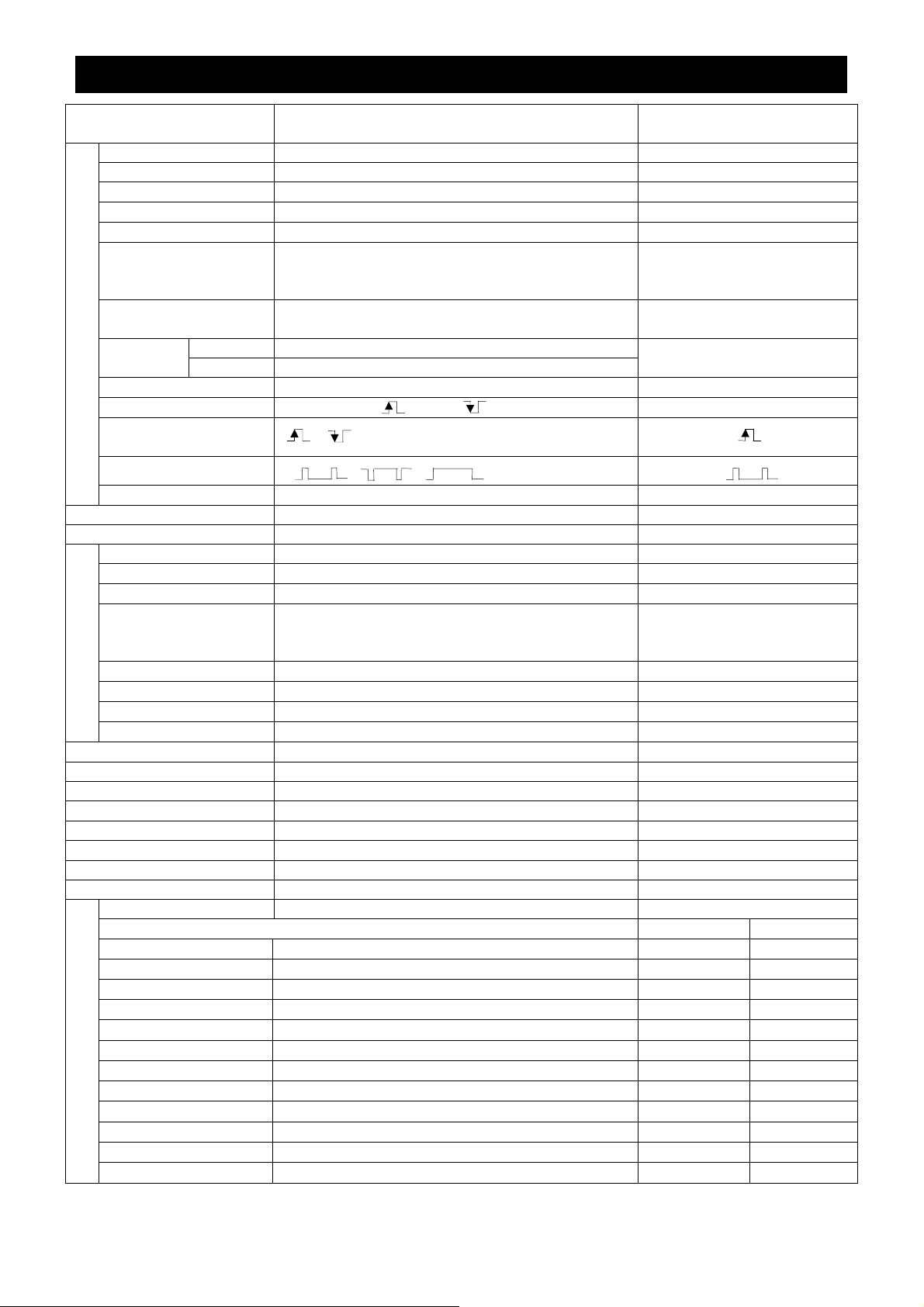
3
ITEMS CONTROLLED BY USING ON SCREEN DISPLAY
Item Available selections
MODE AUTO, MANUAL, SS, EXT TRIG MANUAL
EXT TRIG 1PULSE SNR, 1PULSE SR, 2PULSE, RS232C 1PULSE SNR
AUTO level
AUTO peak/average
AUTO response speed
AUTO area PRESET A, PRESET B, PRESET C, PRESET D,
Electronic shutter
MANUAL speed OFF, 1/120s, 1/250s, 1/500s, 1/1000s, 1/2000s,
Syncro. FLD 1/625H to 310/625H, OFF, 1FRM to 255FRM
scan FRM 1/625H to 310/525H, OFF, 2FRM to 256FRM
Storage mode FLD, FRM FLD
Freeze operation FRONT, TRIG , TRIG FRONT
Trigger
(1PULSE SNR/SR)
Trigger(2PULSE)
1PULSE exposure time 0.06ms to 20ms 20ms
AUTO maximum gain 0dB to 20dB 10dB
MANUAL gain 0dB to 20dB 0dB
Color temperature 3200K, 5600K 3200K
AWB R PAINT
White balance
AWB B PAINT
AWB area PRESET A, PRESET B, PRESET C, PRESET D,
ATW R PAINT
ATW B PAINT
MANUAL R GAIN
MANUAL B GAIN
Gamma correction switching ON, OFF ON
Gamma correction level
Black gamma LOW, NORMAL, HIGH NORMAL
Detail gain
Detail boost frequency LOW, NORMAL, HIGH NORMAL
Master pedestal
Chroma gain
Digital noise reduction(DNR) ON, OFF OFF
Correction ON/OFF ON, OFF ON
JK-TU62H use JK-TU63H use
R hue
Matrix color correction
R gain
G hue
G gain
B hue
B gain
Ye hue
Ye gain
Cy hue
Cy gain
Mg hue
Mg gain
-100 − 0 − 100
00:10 − 05:05 − 10:00 05:05
1 − 5 − 10
PRESET E, USER
(USER area is possible to set in 64 zones)
1/4000s, 1/10000s
,
, ,
-10 − 0 − 10
-10 − 0 − 10
PRESET E, USER
(USER area is possible to set in 64 zones)
-10 − 0 − 10
-10 − 0 − 10
-100 − 0 − 100
-100 − 0 − 100
-10 − 0 − 10
-7(OFF) − 0 − 7
-50 − 0 − 50
-128 − 0 − 127
-15 − 0 − 15
-15 − 0 − 15
-15 − 0 − 15
-15 − 0 − 15
-15 − 0 − 15
-15 − 0 − 15
-15 − 0 − 15
-15 − 0 − 15
-15 − 0 − 15
-15 − 0 − 15
-15 − 0 − 15
-15 − 0 − 15
Preset value
(Factory setting)
0
5
PRESET A
OFF
OFF
0
0
PRESET A
0
0
0
0
0
0
0
0
0 0
0 0
3 0
3 0
0 0
2 -1
0 0
2 -1
0 0
0 0
0 0
0 0
- 7 -
Item Available selections
Ext.
Sync.
H phase adjustment
SC 0/180 0, 180 0
SC phase adjustment
-100 − 0 − 100
-128 − 0 − 127
OUTPUT 1 RGB, Y/PR/PB RGB
2 VBS, Y/C VBS
Shading correction mode SET, MANUAL, OFF OFF
Manual shading correction
-128 − 0 − 127
RGB SYNC G, ALL ON, ALL OFF G
FREEZE DISP ON, OFF ON
Negative/Positive inversion NEGA, POSI POSI
Detail signal output ON, OFF OFF
RS232C baud rate 9600bps, 19200bps 9600bps
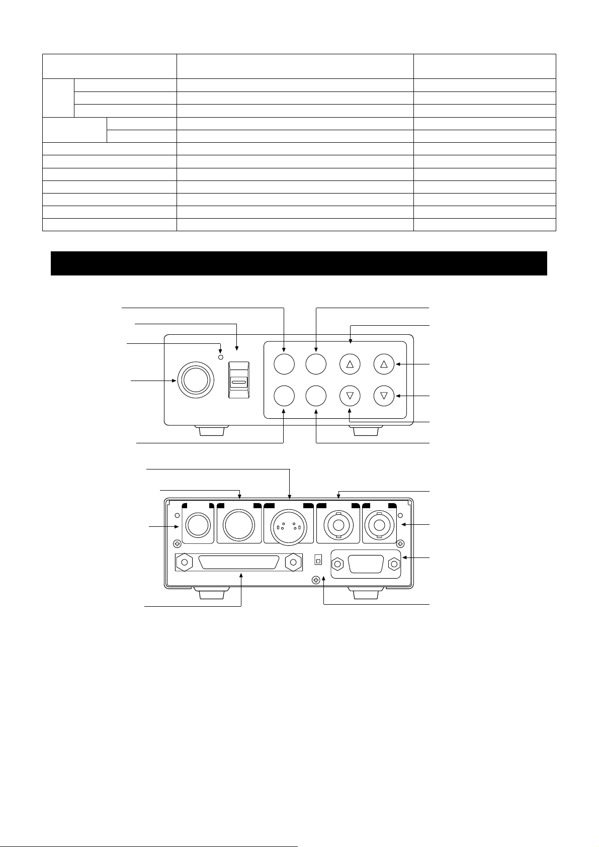
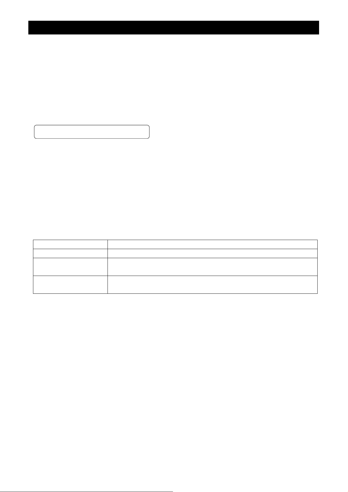
4....NAMES AND FUNCTIONS
Preset value
(Factory setting)
0
0
0
④FILE button
③POWER switch
②POWER LED
①Camera cable
terminal
CAMERA
POWER
ON
OFF
FILE DISP
FREEZE
PAGE
(SHD) (AWB)
MENU DATA
(ABB)
⑥DISP button
⑧MENU UP
(SHD) button
⑩DATA UP
(AWB) button
⑪DATA DOWN
(ABB) button
⑨MENU UP(SHD) botton
⑤FREEZE button
⑭S-VIDEO terminal
⑬DC IN/SYNC terminal
⑫DC IN 12V terminal
⑰DIGITALterminal
DC IN 12V
DC IN/SYNC
DIGITAL
S-VIDEO
ON
OFF
KEY LOCK
EXT SYNC
RGB
VIDEO
⑦PAGE button
⑮EXT.SYNC terminal
⑯VIDEO terminal
⑲RGB terminal
⑱KEY LOCK switch
- 8 -

① Camera cable terminal
② POWER LED
③ POWER switch
④ FILE button
⑤ FREEZE button
⑥ DISP button
⑦ PAGE button
⑧ MENU UP(SHD)button
⑨ MENU DOWN button
⑩ DATA UP(AWB)button
⑪ DATA DOWN
(ABB)button
⑫ DC IN 12V terminal
⑬ DC IN/SYNC terminal
The camera cable is connected.
Lights when the power is turned on.
Turns on or off the power supply.
Used when switching the scene files.
Used when switching to th e freeze menu and when r eturning from the freeze
menu to the camera menu.
Used when switching the display.
Used when switching to the menu and when selecting the menus.
Select the function to be c onf irmed or chan ged on the m enu. (Also used when
performing the auto shading correction.)
Select the function to be confirmed or changed on the menu.
Changes the valu e of the f unction selec ted by the MENU (UP/DOW N) button.
(Also used when using AWB.)
Changes the valu e of the f unction selec ted by the MENU (UP/DOW N) button.
(Also used when using ABB.)
Accept a DC power input (12V).
HD and VD signals are input/output. When the random trigger operation is
used, the trigger signal is input and the index signal is output.
⑭ S-VIDEO terminal
⑮ EXT. SYNC terminal
⑯ VIDEO terminal
⑰ DIGITAL terminal
⑱ KEY LOCK switch Enables/disables buttons ④ to ⑪.
⑲ RGB terminal
Outputs Y (luminance) and C (color) signals.
Used when the camera output s ignal is synchronized by the external signal.
(BNC connector)
Outputs VBS output. Connected to a monitor, VTR, etc. (BNC connector)
LVDS format digital video signal output and control signal input/output
terminal. This terminal also includes an RS232C format external control pin.
Used as the connector terminal for Y/C or VBS output, RGB or Y/P
and SYNC output.
R/PB
output,
- 9 -
....
5
CONNECTION
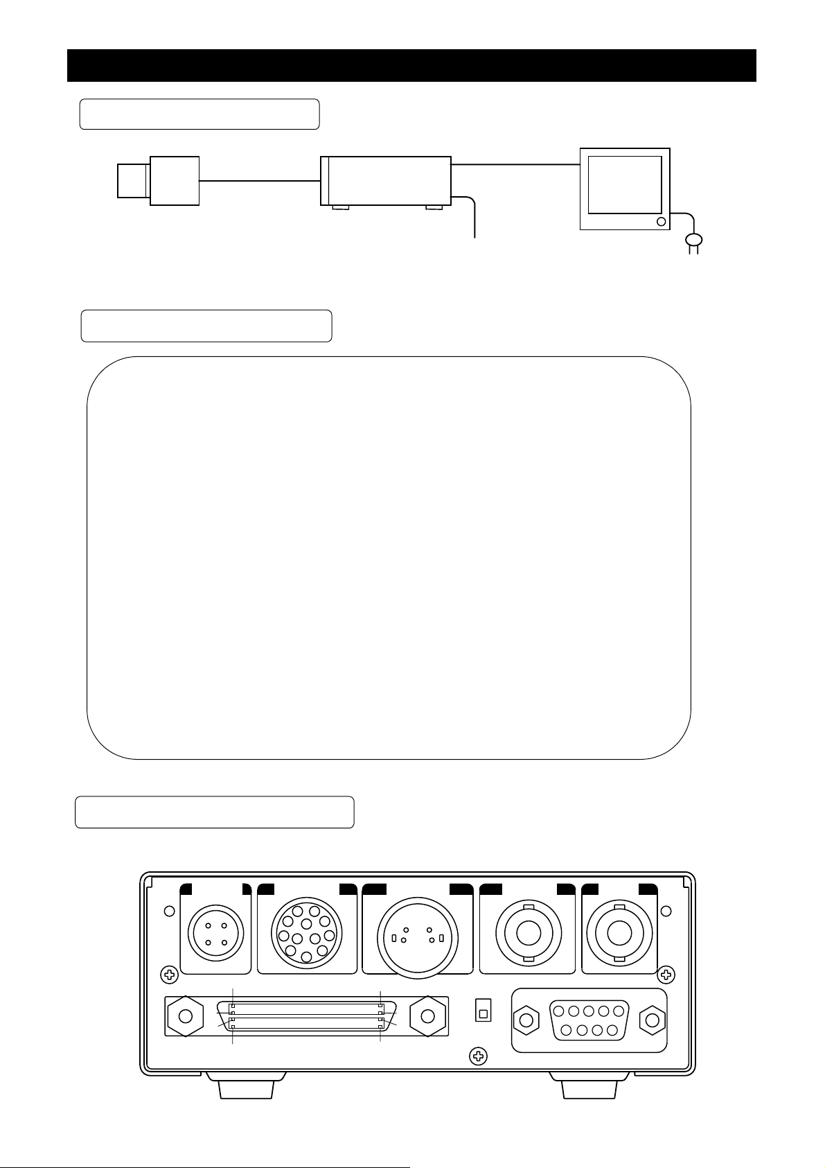
5....1 Standard Connection
Lens
Camera cable
option)
(
IK-TU61
Camera
Control unit
VIDE
DC IN 12V
Coaxial
Cable
75
Ω
Camera head
option
(
)
DC power
supply
5....2 Caution on Connection
・
Please use only optional camera heads model # JK-TU62H or JK-TU63H with this camera
controller. Use of another head may cause damage.
・
When connecting the camera cables, be sure to turn off the camera control unit and
the other equipment connected.
・
For DC power supply connecting to DC IN 12V terminal, use Class II DC power supply
approved according to EN60950 in Europe.
(Betrieb nur mit zertifiziertem AC-Adapter nach EN60950)
When camera is used in USA, use UL listed and/or CSA approved ungrounding type
AC adaptor with the specifications described below.
monitor
:
Power supply voltage
Current rating
Ripple voltage
Connector
・
If the screw on the camera connector portion of the camera cable looses, noise may
DC12V±10%
:
More than 830mA, Less than2.5A
:
Less than 50mV(p-p)
:
HR10A-7P-4S by HIROSE electronics Co. Ltd
Pins 1, 2 : 12V
Pins 3, 4 : GND
appear on the screen. So be sure to tighten the connector fully.
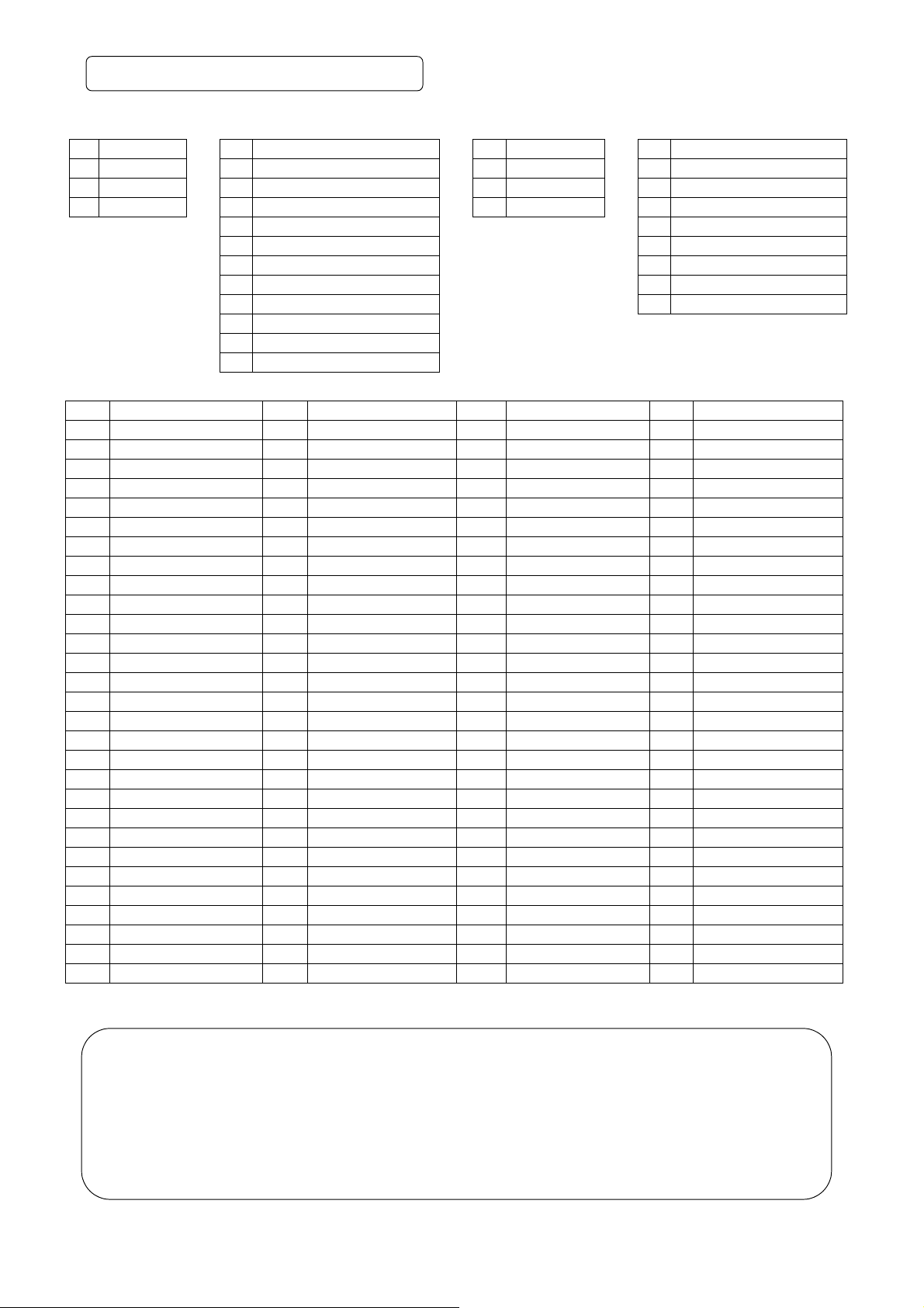
5....3 Connection on Back Panel
Back panel view
DC IN 12V
3
1
4
2
DC IN/SYNC
1
9
2
8
10
11 12
4
7
6
5
3
S-VIDEO
3
4
2
1
EXT SYNC VIDEO
30
60
90
120
DIGITAL
1
31
61
91
ON
OFF
KEY LOCK
5
9
RGB
432
8
1
6
7
- 10 -
....
5
3A Connector Pin Assignments
DC IN 12V DC IN/SYNC S-VIDEO RGB
1 +12V
2 +12V
3 GND
4 GND
1 GND
2 +12V
3 GND(for INDEX)
4 INDEX
5 GND(for HD)
6 HD OUT
7 VD OUT
8 GND(for TRIGGER)
9 TRIGGER
10 VD IN
11 HD IN
12 GND(for VD)
1 GND
2 GND
3 Y
4 C
1 GND(for VBS,Y/C)
2 GND(for R/G/B,Y/PR/PB)
3 R/PR OUT
4 G/Y OUT
5 B/PB OUT
6 VBS/Y OUT
7 SYNC OUT
8 GND(for SYNC)
9 -/C OUT
DIGITAL
1 R0 (+) 31 R0 (-) 61 GND 91 GND
2 R1 (+) 32 R1 (-) 62 PIXEL CLK (+) 92 PIXEL CLK (-)
3 R2 (+) 33 R2 (-) 63 FRAME EN (+) 93 FRAME EN (-)
4 R3 (+) 34 R3 (-) 64 FIELD ID (+) 94 FIELD ID (-)
5 R4 (+) 35 R4 (-) 65 LINE EN (+) 95 LINE EN (-)
6 R5 (+) 36 R5 (-) 66 TRIGGER D (+) 96 TRIGGER D (-)
7 R6 (+) 37 R6 (-) 67 RESERVE (OUT +) 97 RESERVE (OUT -)
8 R7 (+) 38 R7 (-) 68 GND 98 GND
9 R8 (+) 39 R8 (-) 69 GND 99 GND
10 R9 (+) 40 R9 (-) 70 NC 100 NC
11 G0 (+) 41 G0 (-) 71 NC 101 NC
12 G1 (+) 42 G1 (-) 72 NC 102 NC
13 G2 (+) 43 G2 (-) 73 NC 103 NC
14 G3 (+) 44 G3 (-) 74 NC 104 NC
15 G4 (+) 45 G4 (-) 75 NC 105 NC
16 G5 (+) 46 G5 (-) 76 NC 106 NC
17 G6 (+) 47 G6 (-) 77 NC 107 NC
18 G7 (+) 48 G7 (-) 78 NC 108 NC
19 G8 (+) 49 G8 (-) 79 NC 109 NC
20 G9 (+) 50 G9 (-) 80 NC 110 NC
21 B0 (+) 51 B0 (-) 81 NC 111 NC
22 B1 (+) 52 B1 (-) 82 NC 112 NC
23 B2 (+) 53 B2 (-) 83 NC 113 NC
24 B3 (+) 54 B3 (-) 84 NC 114 NC
25 B4 (+) 55 B4 (-) 85 GND 115 GND
26 B5 (+) 56 B5 (-) 86 GND 116 GND
27 B6 (+) 57 B6 (-) 87 TXD 117 NC
28 B7 (+) 58 B7 (-) 88 RXD 118 NC
29 B8 (+) 59 B8 (-) 89 GND 119 NC
30 B9 (+) 60 B9 (-) 90 GND 120 GND
* When using pins to remote(pins 87 to 89), please consult with your dealer.
Precautions on DIGITAL terminal :
・ Interference occurring inside the cable may accidentally activate the Trigger if the TRIGGER D
inputs (pins 66 and 96) are open.
If the TRIGGER D input is not us ed, the TRIGGER D input p in should be either not connected or
connected to RESERVE output pin (pins 67 and 97) ie: (connect pin 66 to pin 67 and pin 96 to 97).
・ The RESER VE p ins ( pi n s 67 and 97) are provided for an add itiona l output. If unused they shoul d be
OPEN or connected to Trigger D.
・ NC pins (pins 117 to 119) should be left OPEN.
- 11 -
....
6
OPERATION
① Referring to the item “ 5. CONNECTION”, connect each equipment correctly.
② Turn on the connected equipment and the camera.
③ W hen using the cam era for the first time and when replacing the c amera cable and t he camera head, be
sure to operate the ABB adjustment in advance, referring to the item “6.1 Automatic Black Balance”.
④ Pointing the lens at the object, operate the lens iris adjustment, focus adjustment, etc.
⑤ Referring to the item “6.2 White Balance”, operate the adjustment.
⑥ Ref erring to the i tems “6.3 Scen e File, 6.4 Gai n, 7. MODE SETTING BY ON SCREEN DI SPLAY”, selec t
the necessary items.
....
6
1 Automatic Black Balance
Black balance adjustment is necessary to get the correct black picture level.
・ Close the lens iris.
・ If the color bar pattern is displayed on the screen or if the index menu/menu is displayed, press the
[DISP] button to disable the c olor bar pattern or the charac ter display. If the cam era is in Freeze Mode,
perform the cancellat ion procedure (refer to the item “6.6 F reeze Operation”) to return t he c amera to Live
Image Mode.
・ Hold the [DATA DOWN] button for approx. 1 second.
・ When the black balance adjustment operation starts, the character ABB blinks on the screen.
・ When the b lack balance adjustm ent operation finishes, t he character ABB ends bl inking and the result
appears for approx. 1 second.
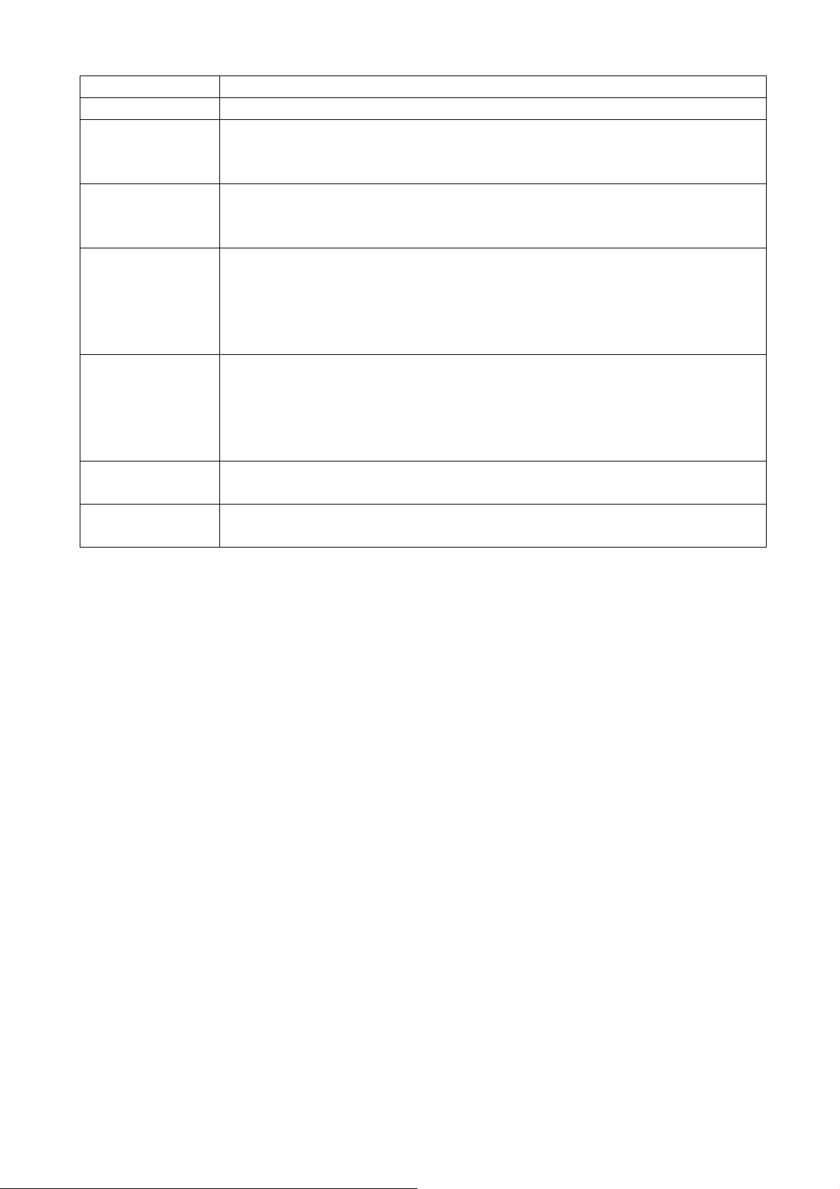
Display Meaning
ABB OK Automatic black balance adjustment finished correctly.
ABB NG
CLOSE LENS
ABB NG Automatic black balance adjustment cannot be performed.
Automatic black balance adjustment cannot be performed because the lens iris
is open. Close the lens iris.
Operate the automatic black balance again.
- 12 -

....
6
2 White Balance
For the white balance adjustment for this unit, ATW (Automatic Trace White balance), AWB (Automatic
White Balance) and M ANU AL ( M anu al whi te bal ance) adj ustments are provided. Referring to th e it ems “7.2
(3) WHT BAL (White balance), 7. MODE SETTING BY ON SCREEN DISPLAY”, select the desired mode.
Outline
Features
Notes
ATW
(
(Automatic Trace White
((
Balance))))
Camera measures the object
color temperature and
adjust the white balance
automatically.
Traces variations of color
temperature and adjusts
the white balance automatically.
If an illumination is low,
white balance may not be
corrected. When the shutter
mode is EXT TRIG or long
the long period exposure
mode, ATW is not available.
(
(Automatic White Balance))))
((
Adjust white balance by
displaying the white object
inside the area set by AWB
menu and pressing the
[DATA UP] button.
Measurement accuracy is
higher than ATW. This
mode is effective when
shooting under less variations of color temperature.
When the shutter mode is
EXT TRIG, AWB is not
available.
AWB
MANUAL
(
(Manual White Balance))))
((
Adjust the white balance
manually using the WHT
BAL menu while shooting
the white object.
Artificial white balance
setting can be set. The
manual adjustment is most
effective under shooting
condition with no color
temperature variation.
Adjustment is performed by
confirming with a vector
scope.
① AWB(Automatic white balance)
・ Set the MODE to AWB on the WHT BAL menu.
Perform the C.TEMP (color temperature conversion) setting, if necessary.
(Refer to the item “7.2 (3) WHT BAL (White balance)”.)
3200K:Appropriate for indoor shooting.
5600K:Appropriate for outdoor shooting.
・ If the color bar pattern is dis played on the s creen or if the index m enu/m enu is displayed, press the [D ISP]
button to disable the color bar pattern or the charact er display on the menu. If the camera is in Freeze
Mode, perform the c anc e lla tion proc e dur e (r ef er to th e item “6.6 Freeze Operation ”) to r etur n th e c amera to
Live Image Mode.
・ Shoot a known white object that fills the area set by the AWB menu (refer to the item “7.2 (3) (3.1) (d)
Changing AWB zone area” ) and push [DATA UP] button for approx. 1 second.
・ The character AWB blinks on the screen when the AWB starts.
・ The character AWB stops blinking when the AWB finishes, and the result is displayed for approx. 1 second.
- 13 -
Display Meaning
AWB OK
AWB NG
LEVEL LOW
AWB NG
LEVEL HIGH
AWB NG
C....TEMP LOW
AWB NG
C....TEMP HIGH
AWB NG
NOT AVAILABLE
AWB NG
② MANUAL(Manual white balance)
・ Set the MODE to MANUAL on the WHT BAL menu.
(Refer to the item “7.2 (3) WHT BAL (white balance)”.)
・ Shoot a known white object, adj ust the white balance adjusting the l evels of R GAIN and B GAIN on th e
menu, confirming with a monitor or a vector scope.
(Refer to the item “7.2 (3) (3.3) Changing each setting in MANUAL mode”.)
Automatic white balance adjustment finished correctly.
Automatic white ba lance adju stment cannot be perform ed because the v ideo level is
too low.
Set the video level properly.
Automatic white ba lance adju stment cannot be perform ed because the v ideo level is
too high.
Set the video level properly.
Automatic white balance adjustment cannot be performed because the color
temperature is too low.
If the C.TEMP is set to 5600K, set to 3200K.
If the message appears with the C.TEMP set to 3200K, change the illumination or
use a color temperature conversion filter.
Automatic white balance adjustment cannot be performed because the color
temperature is too high.
If the C.TEMP is set to 3200K, set to 5600K.
If the message appears with the C.TEMP set to 5600K, change the illumination or
use the color temperature conversion filter.
Automatic white balance adj ustm ent cannot b e perfor m ed because the s hutter s peed
mode is EXT TRIG mode.
Automatic white bal ance adj ustm ent cannot be perf orm ed for other reasons . Suc h as
no white area is included in an object, etc.
- 14 -

....
6
3 Scene File
Three scene files (A, B, C) are availa ble as user memories f or this uni t. These ar e selectab le dependin g on
shooting conditions. By using the [FILE] button, the camera operation is changed immediately from the
currently selected Scene File to the next. (Refer to the item “7. MODE SETTING BY ON SCREEN
DISPLAY”.)
・ While any menu is displayed, pressing the [FILE] button will display the menu settings for the next Scene File:
FILE A →→→→ FILE B →→→→ FILE C
・ When the [FILE] button is pressed wh ile the cam era is in live im age m ode, the current s cene file s electio n
at that time is displ a yed f or appr ox . 3 sec onds in t he u pper ri ght c orner of the screen. If the [FILE] but ton is
pressed again while the position is displayed, the scene file cycles as described above.
6....4 Gain
When the image is dark even if the lens iris is open, change the ga in (video gain) to get the proper v ideo
level.
For the gain adjustment of the unit, AUTO (Autom atic gain control), MANUAL (Manua l), OFF (0 dB) modes
are provided. Select the mode on the GAIN menu. (Refer to the item “7.2 (2) GAIN (Video gain)”.)
① AUTO(Automatic gain control)
When the output is low, the gain is automatically adjusted to a suitable video level.
The maximum value of the gai n is 20 dB, an d can be s et fr om 0 to 20d B in 1d B st eps. (Refer to the it em
“7.2 (2) (2.1) Changing the maximum gain in AUTO (Automatic gain control) mode”.)
Video level (LEVEL), peak average value ratio (PEAK/AVE), and measurement light area (AREA) is same
as the setting on th e automatic s hutter. (Refer to the item “7.2 (1) (1.1) Changing each s etting in AUT O
mode”.)
② MANUAL(Manual gain)
Gain adjustment is performed o n the GAIN menu. The adj ustment rang e is fr om 0 to 20dB i n 1dB steps .
(Refer to the item “7.2 (2) (2.2) Changing the gain in MANUAL mode”.)
③ OFF
Gain is fixed at 0 dB.
- 15 -
6....5 Shading Correction
Due to the lens used or the env ironmental con dition, ver tical color s hading ma y occur at the top and bot tom
of the screen. In this case, the shading correction can decrease the color shading. For the shading correction
of the unit, SET (Automatic shading correction), MANUAL (Manual shading correction), and OFF (no shading
correction) modes are provided. Select the mode on the OPTION menu. (Ref er to the item “7.2 (7) (7.3)
Changing shading correction mode”.)
① SET(Auto shading)
・ W hen the s hutter spe ed m ode is set t o EXT TR IG or the SS l ong p eriod ex pos ure m ode, t he aut om atic
shading correction cannot be performed.
・ If the color bar pattern is displayed on the screen or if the index m enu/menu is displayed, press the
[DISP] button to remove them from the screen. If the camera is in Freeze Mode, perform the
cancellation procedure ( refer to the item “6.6 Freeze Operation” ) to return the camera to Live Image
Mode.
・ Push the [MENU UP] button for approx. 1 second.
・ When the automatic shading correction operation starts, the character SHD blinks on the screen.
・ When the aut omatic s hading corr ection opera tion term inates, the c haracter SHD ends blinking and the
result is displayed for approx. 1 second.
Display Meaning
SHD OK
SHD OK
LIMIT
SHD NG
LEVEL LOW
SHD NG
LEVEL HIGH
SHD NG
NOT AVAILABLE
② MANUAL(Manual Shading)
Perform the correction amount sett in g on th e OPTION menu, confirming with a monitor or a vector scope.
(Refer to the “7.2 (7) (7.4) Changing the manual shading correction setting”.)
③ OFF
The status is no shading correction.
* The shading correction is effective when the lens iris or zoom ratio is fixed. Use the unit with
SHADING OFF for variable lens conditions.
Automatic shading correction operation terminated correctly.
Automatic shading correction operation terminated, however, the correction
necessary exceeds the camera’s range so the maximum possible value is applied.
Automatic shading correction cannot be performed because the video level is too
low. Set the video level properly.
Automatic shading correction cannot be performed because the video level is too
high. Set the video level properly.
Automatic shading correction operation cannot be performed because the shutter
speed mode is the EXT TRIG mode or the SS long period exposure mode.
- 16 -
 Loading...