

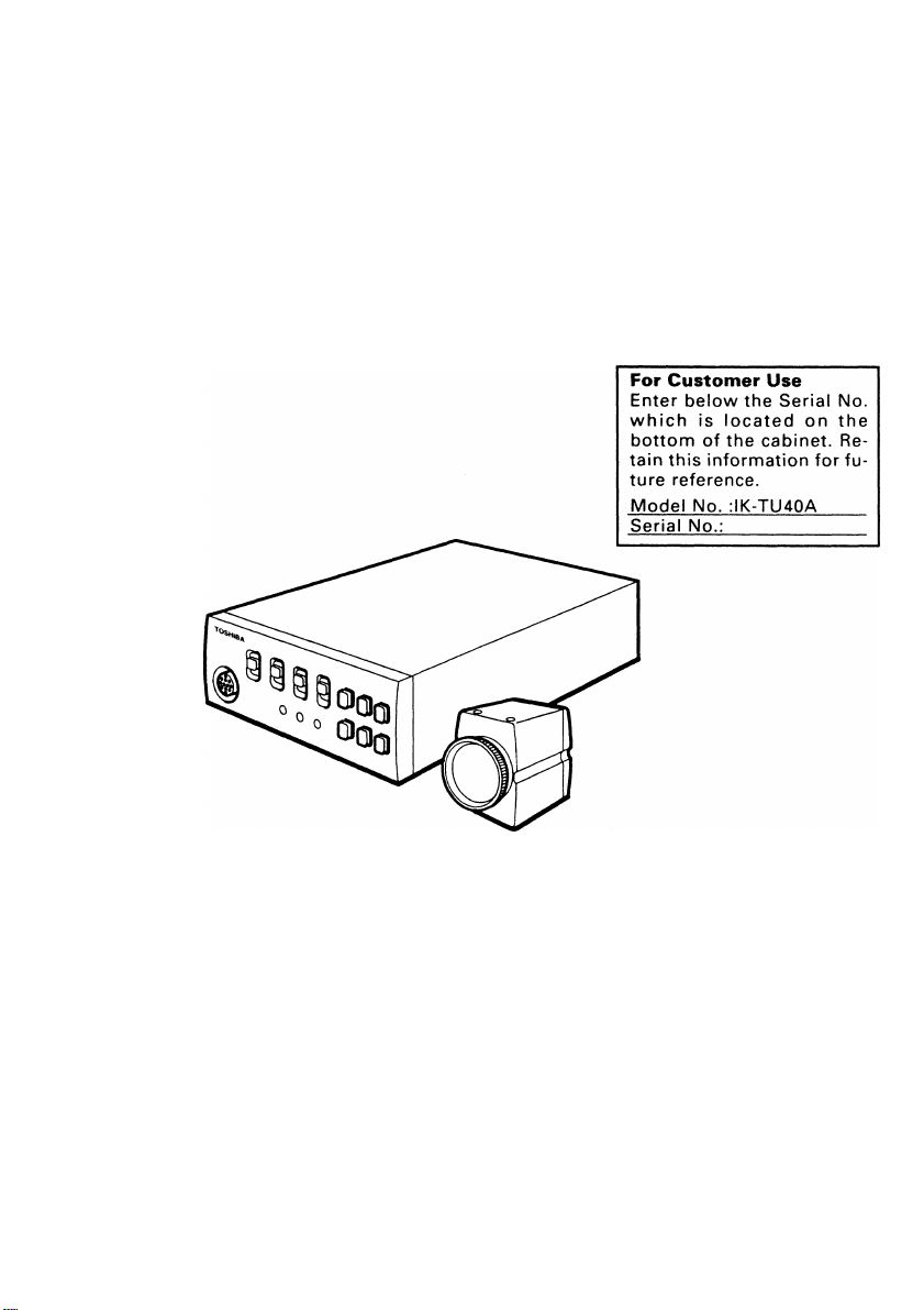
TOSHIBA
3 CCD COLOR CAMERA
IK-TU40A
INSTRUCTION MANUAL
INFORMATION
This equipment has been tested and found to comply with the limits for a Class A digital device,
pursuant to Part 15 of the FCC Rules. These limits are designed to provide reasonable protection
against harmful interference when the equipment is operated in a commercial environment. This
equipment generates, uses, and can radiate radio frequency energy and, if not installed and used
In accordance with the instruction manual, may cause harmful interference to radio communica
tions. Operation of this equipment in a residential area is likely to cause harmful interference in
which case the user will be required to correct the interference at his own expense.
USER-INSTALLER CAUTION: Your authority to operate this FCC verified equipment could be
voided If you make changes or modifications not expressly approved by the party responsible for
compliance to Part 15 of the FCC rules.
This Class A digital apparatus meets all requirements of the Canadian Interference Causing Equip
ment Regulations.
Cet appareil numérique de la classe A respecte toutes les exigences du Règlement sur le matériel
brouilleur du Canada.

TABLE OF CONTENTS
1. COMPONENTS........................................................................................................................4
2. SPECIFICATIONS....................................................................................................................4
3. ITEMS CONTROLLED BY USING ON SCREEN DISPLAY...................................................5
4. NAMES AND FUNCTIONS......................................................................................................6
5. CONNECTION......................................................................................................................... 8
5.1 Standard Connection........................................................................................................8
5.2 Cautions on Connection...................................................................................................8
5.3 Connection on Back Panel
6. OPERATION.......................................................................................................................... 10
6.1 Automatic Black Balance................................................................................................10
6.2 White Balance................................................................................................................10
6.3 Scene File...................................................................................................................... 12
6.4 Gain................................................................................................................................12
6.5 Shading Correction ....................................................................................................... 12
7. MODE SETTING BY ON SCREEN DISPLAY.......................................................................14
7.1 Using the Menus............................................................................................................14
7.2 Menus.............................................................................................................................16
(1) SHUTTER (Electronic shutter).......................................................................................16
(1.1) Changing each setting in AUTO mode
(1.2) Changing each setting in MANU mode...................................................................18
(1.3) Changing each setting in SS (syncro. scan) mode.................................................18
(1.4) Changing each setting in 1 PULSE mode...............................................................19
(2) GAIN (Video gain)..........................................................................................................19
(2.1) Changing the maximum gain in AUTO
(Automatic gain control) mode................................................................................19
(2.2) MANU (manual) mode menu................................................................................. 20
(2.3) NORM (0 dB) mode menu
(3) WHT BAL (white balance)..............................................................................................20
(3.1) ATW (Automatic Trace White Balance) mode menu
(3.2) Changing the AWB (Automatic White Balance) mode setting... 20
(3.3) MANU (manual) mode menu..................................................................................21
(4) PROCESS (Process).....................................................................................................22
(4.1) Changing the gamma correction ON/OFF..............................................................22
(4.2) Changing gamma correction level
(4.3) Changing black gamma correction level.................................................................23
(4.4) Changing two-dimension low pass filter................................................................ 23
(4.5) Changing detail (outline) gain.................................................................................23
(4.6) Changing detail boost frequency
(4.7) Changing master pedestal......................................................................................24
.............................................................
...................................................................
......................................................................................
..............................................
..........................................................................
............................................................................
.................................
9
16
20
20
22
23

(5) SYNC (sync) ..................................................................................................................24
(5.1) INT screen...............................................................................................................24
(5.2) Changing EXT setting..............................................................................................24
(6) OPTION..........................................................................................................................25
(6.1) Changing OUTPUT 1 output...................................................................................25
(6.2) Changing OUTPUT 2 output...................................................................................25
(6.3) Changing Negative/Positive inversion switch
(6.4) Changing detail signal output..................................................................................25
(6.5) Changing shading....................................................................................................26
(6.6) Changing G SYNC..................................................................................................26
(7) Setting USER area.........................................................................................................26
(8) Setting to factory setting status......................................................................................27
7.3 External Sync.................................................................................................................27
(1) External sync signal input conditions............................................................................ 27
(2) External sync frequency range.......................................................................................28
(3) Using the camera with external sync signal
(3.1) H (horizontal) phase adjustment.............................................................................28
(3.2) SC (Sub carrier) phase adjustment.........................................................................28
7.4 1 PULSE....................................................................................................................... 28
7.5 Syncro. Scan Operation.................................................................................................29
(1) Setting by 1H..................................................................................................................29
(2) Setting by the frame.......................................................................................................29
8. CAUTIONS ON USE AND INSTALLATION
9. BEFORE MAKING A SERVICE CALL...................................................................................30
10. EXTERNAL APPEARANCE DIAGRAM..............................................................................31
................
.........................................................
..................................................................
.........................................................30
25
28
1. COMPONENTS
(1) Camera head (without lens, protection cap attached)
(2) Camera control unit....................................................................................... 1
(3) Accessories.......................................................................................................1
(a) Instruction manual....................................................................................1
(b) Warranty card.......................................................................................... 1
......................................
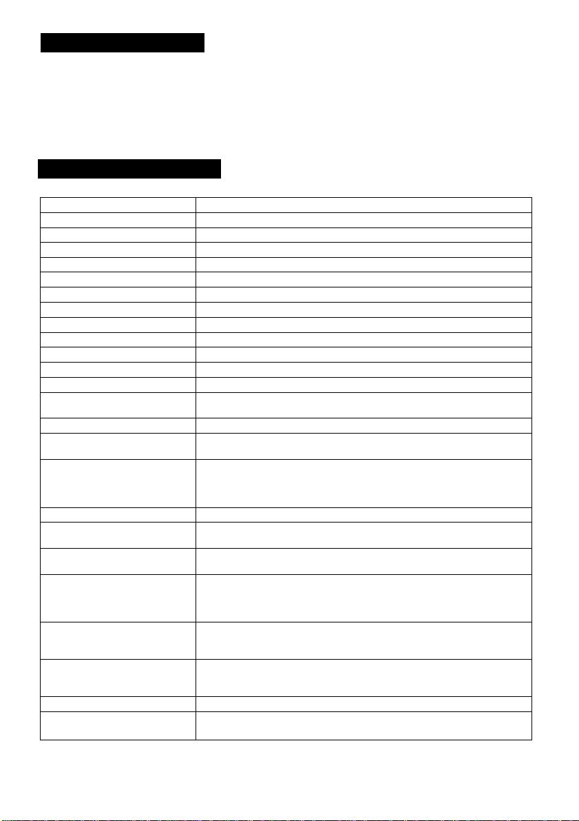
2. SPECIFICATIONS
Power supply
Power consumption
Pick-up system
Image sensor
Effective pixels
Scanning system
Scan frequency
Sync system
Horizontal resolution
Sensitivity
Minimum ilumination
SN ratio
Lens mount
Ambient operating
temperature
Ambient humidity
Weight
External dimension
(except for protruded
portions)
Scene file (user memories)
White balance
Gain
Output signal
External sync input
Sync signal output
1 pulse trigger
Index output:
DC12V ±10%
7.4W
RGB, 3 CCD, Micro prism system
1/3 inch IT-CCD
Horizontal: 768 pixels. Vertical: 494 pixels
2:1 interlace
Horizontal: 15.734kHz, Vertical: 59.94Hz
Internal/External (automatic switching)
750 TV lines
F8 (2000 lx, 3000K)
10 lx. (F2.2, Sensitivity +18 dB, 3000K)
62 dB standard
C mount (flange back: 17.526 mm in-air)
32 ~ 104°F ( 0 ~ 40°C )
Less than 90%
Camera head: Approx. 2.1 oz (60g),
Camera control unit: Approx. 1.48 lbs (670g)
Camera head: 1.27" (W) x 1.57" (H) x 1.58" (D)
Camera control unit: 4.33" (W) x 1.57" (H) x 6.14" (D)
A, B, C
ATW (Automatic tracing white balance),
AWB (Automatic white balance), MANU (Manual)
AUTO (Automatic gain control),
MANU (Manual), NORM (0 dB)
VBS: 75П unbalanced, BNC connector, NTSC standard
Y/C: 75Q unbalanced, S terminal
RGB or Y/PR/PB: 75i2 unbalanced, D sub 9 pin connector
VBS or Y/C: 750 unbalanced, D sub 9 pin connector
VBS/BB: 750 unbalanced. Sync negative BNC connector
HDorVD: 2 ~ 5V(p-p) Negative
SYNC: 2.5 ± IV(p-p), 750 unbalanced
HDorVD: 5V V(p-p), Negative,
TRIGGER: L level: Less than 0.5V, H level: 4 ~ 5V, Positive
INDEX: L level: Less than 0.5V, H level: 4 ~ 5V
SYNC 0.286V, Burst 0.286V
Loatffrnpedance: More than 10 kO
Negative , Load impedance: More than 10 kO
(32.5 (W) X 40 (H) X 40.2 (D) mm)
(110 (W) X 40 (H)x 156(D) mm)
1
Remote interface:
Option (Optional parts)
Serial data interface (RS-232C standard)
EXC-T406 (Camera cable 21'10" (6.5m))
EXC-T403 (Camera cable 9' 9" (3m))
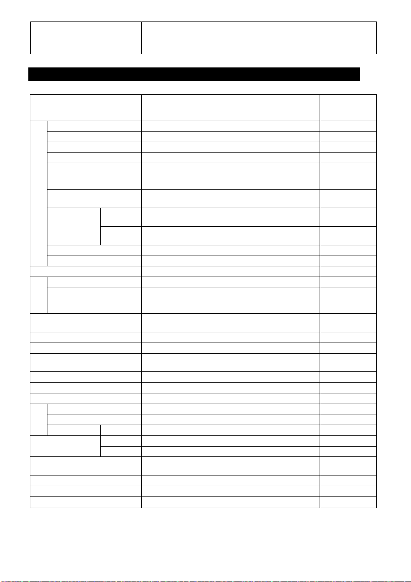
3. ITEMS CONTROLLED BY USING ON SCREEN DISPLAY
Item
MODE
AUTO level
AUTO peak (average)
AUTO response speed
AUTO area
CD
13
-C
</)
o
MANU speed
'c
o
+->
o
Syncro.
LU
scan
FLD
FRM
AUTO, MANU, SS, 1 PULSE
-99 '^00-99
00:10 05:05 ~ 10:00
01 ~ 05 ~ 10
PRESET A , PRESET B, PRESET C, PRESET D,
USER
(USER area is possible to set in 64 zones.)
OFF, 1/100s, 1/250S, 1/500s, 1/1000s, 1/2000S,
1/4000S, 1/IOOOOs
001/525H - 260/525H, OFF,
001FRM ~ 255FRM
001/525H ^ 260/525H, OFF,
001FRM ~ 256FRM
1 PULSE
0.06ms ~ 16ms
Storage mode FLD, FRM
AUTO maximum gain
Offset
OQ
Area
1
Gamma correction
switching
Gamma correction level
Black gamma
Two-dimension low pass
filter (2D LPF)
00 dB ~ 18 dB
-10 - 00 ~ 10
PRESET A, PRESET B, PRESET C, PRESET D,
USER
(User area is possible to set In 64 zones.)
ON, OFF
-10 ~ 00 10
LOW, NORM, HIGH
ON, OFF
Detail gain -5 (OFF) ~ 0 ~ 5
Detail boost frequency
Master pedestal
H phase adjustment
4-: ^
SC 0/180 0, 180
SC phase ad
OUTPUT
Negative/Positive
inversion
ustment
1
2
Detail signal output
LOW, NORM, HIGH
-50 ~ 00 ~ 50
-99 ~ 00 ~ 99
-99 -00-99
RGB, Y/PR/PB
VBS, Y/C
NEGA, POSI
ON, OFF
Shading correction ON, OFF
G SYNC
ON, OFF
Available selections
Preset value
(Factory
setting)
MANU
00
05: 05
05
PRESET A
OFF
OFF
-
16ms
FLD
09dB
00
PRESET A
ON
00
NORM
OFF
0
NORM
00
00
0
00
RGB
VBS
POSI
OFF
OFF
ON

4. NAMES AND FUNCTIONS
® Prism faceplate
' Lens mount (3) Cameracable terminal
® Mounting screws
f—
1
Front
Side Rear
Ohmm« <&iMriNral Itaill
® W.B. switch
(D FILE switch (D POWER light-
® POWER LED
© Camera cable
terminal-
> Manual WB controls> GAIN adjustment
controls-----------------
Bottom
' GAIN switch
' DISPLAY button
'MENU UP (SHD) button
►O POWER FILE W.B. GAIN DISP (SHD) (AWB)
' DATA UP (AWB) button
' DATA DOWN
(ABB) button
MENU DOWN button
' PAGE button
Front

© Prism faceplate
® Lens mount
@ Camera cable terminal
® Mounting screws
® None
® Camera cable terminal
® POWER LED
® POWER switch
® FILE switch
® W.B. switch
® GAIN switch
® Manual WB controls
® GAIN adjustment controls
® DISPLAY button
® PAGE button
® MENU UP (SHD) button
® MENU DOWN button
® DATA UP (AWB) button
® DATA DOWN (ABB) button
@ DC IN 12V terminal
@ DC IN/SYNC terminal
S-VIDEO terminal
EXT. SYNC terminal
VIDEO terminal
RGB terminal
HDA/D switch
REMOTE terminal
The protection cap is attached on the lens mount por
tion. After removing the cap, mount the lens. Be careful
not to scratch or touch the optical area.
C mount lens is mounted.
The camera cable is connected.
Screw holes to fix the camera head mount. (M3 depth of
camera section: 4mm)
The camera cable is connected.
Lights when the power is turned on.
Turns on or off the power supply.
Switch the scene files. (A/B/C)
Switch the white balance mode. (ATW/AWB/MANU)
Switch the gain mode. (AUTO/MANU/NORM)
Adjust R and B gains when the white balance switch ®
is set to MANU.
Adjust video signal gain when the gain switch ® is set to
MANU.
Used when switching the display.
Used when switching to the menu and when selecting
the menus.
Select the function to be confirmed or changed on the
menu. (Also used when performing the shading correc
tion.)
Select to confirm the function or to change the menu.
Changes the value of the function selected by the MENU
(UP/DOWN) button. (Also used when using AWB.)
Changes the value of the function selected by the MENU
(UP/DOWN) button. (Also used when using ABB.)
Accept a DC power Input (12V).
When DC IN 12V terminal @ is not used, accept DC12V
input. HD and VD signals are input/ou^ut. (The input/
output is switched by the HD/VD switch @.) When 1 pulse
operation is used, the trigger signal is input and the in
dex signal is output.
Outputs Y (luminance) and C (color) signals.
Used when the camera output signal is synchronized by
the external signal. (BNC connector)
VBS output. Connected to a monitor, VTR, etc. (BNC con
nector)
Used as the connector terminal for Y/C or VBS output 2,
or A, RGB or Y/Pr/Pb output, or SYNC output.
Switch input/output of HD, VD signals at DC IN/SYNC
terminal @.
Switch terminal resistor when HD and VD signals are
input.
Used when controlling functions of the camera by RS232C.
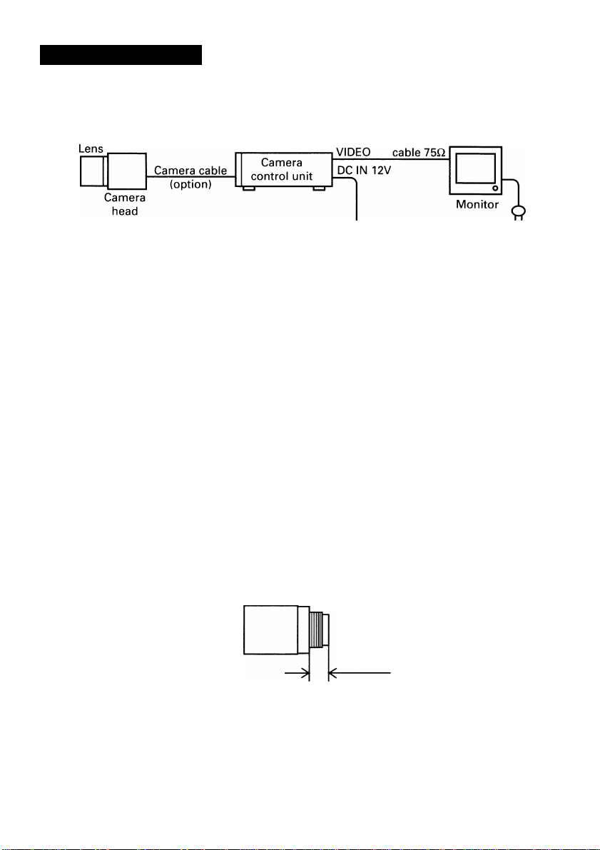
5. CONNECTION
S.1
When connecting the camera cables, be sure to turn off the camera control unit
and the other equipment connected.
For DC power supply connecting to DC IN 12V terminal, use UL listed and/or CSA
approved ungrounding type AC adaptor with the specifications described below.
Power supply voltage: DC12V ± 10%
Current rating: More than 830mA, less than 2.5A
Ripple voltage: Less than 50mV(p-p)
Connector: HR10A-7P-4S by HIROSE electronics Co. Ltd.
We suggest to use a C mount lens for 3CCD camera.
When using other lens, the best camera performance of this camera may not be
obtained.
(For example, low resolution may occur, focus may be lost through the range of
a zoom lens, and flare ghost shading may occur.)
Furthermore, in order to avoid damaging the mounting portion of the camera
head, use a lens which projection dimension from the mounting base is less than
0.157" (4 mm).
Coaxial
DC power
supply
Pins 1, 2: 12V
Pins 3, 4: GND
Less than 0.157"
(4mm)
If the screw on the camera connector portion of the camera cable looses, noise
may appear on the screen. So be sure to tighten the connector fully.
8
UP 8lNBMElfc[ VNOMHMIf^
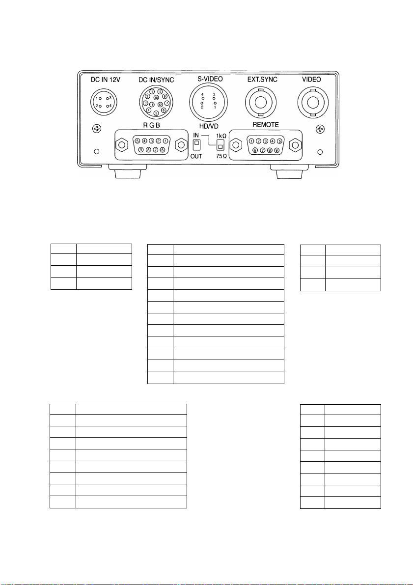
Back panel view
Stt3Jk CkMMMMdhMiF Mfatt i
DC IN 12V
1
+ 12V
2
+ 12V
3 GND
4
GND
RGB
1
GND (for VBS, Y/C)
2
GND for R/G/B, Y/Pr/Pb)
3
r/pr out
4
G/Y OUT
5 b/pb out
6 VBS/Y OUT
7
SYNC OUT
8 GND (for SYNC)
9 -/C OUT
When using the REMOTE terminal, please consult with your dealer.
DC IN/SYNC
1 GND
+12V
2
GND (for INDEX)
3
4 INDEX
5 GND (for HD)
HD (IN/OUT)
6
7
VD (IN/OUT)
8 GND (for TRIGGER)
TRIGGER
9
GND
10
11 +12V
12
GND (for VD)
S-VIDEO
1 GND
2
3
4
REMOTE
1
2 TXD
3
4
5
6
7
8
9 NC
GND
Y
C
NC
RXD
DSR
GND
DTR
CTS
RTS

6. OPERATION
© Referring to the item '"5. CONNECTION", connect each equipment correctly.
® Turn on the connected equipment and the camera.
@ When using the camera for the first time and when replacing the camera cable and the
camera head, be sure to operate the ABB adjustment in advance, referring to the item
"6.1 Automatic Black Balance".
® Facing the lens to the object, operate the lens iris adjustment, focus adjustment, etc.
® Referring to the item "6.2 White Balance", operate the adjustment.
® Referring to the items "6.3 Scene File, 6.4 Gain, 7. MODE SETTING BY ON SCREEN
DISPLAY", select the necessary items.
[ #«1 AiHNMWMirtlt Wtawii Mkamm
Black balance adjustment is necessary to get the correct black picture level.
• Close the lens iris.
• Disable the color bar pattern or the character display by pushing the [DISP] button, if
necessary.
• Flold the [DATA DOWN] button for approx. 1 second.
• When the black balance adjustment operation starts, the character ABB blinks on the
screen.
• When the black balance adjustment operation finishes, the character ABB ends blink
ing and the result appears for approx. 1 second.
«.2 Wliil*
For the white balance adjustment for this camera, ATW (Automatic Trace White balance),
AWB (Automatic White Balance) and MANU (manual white balance) adjustments are pro
vided. Select the desired mode by the [W.B.] switch.
Display
ABB OK Automatic black balance adjustment finishes correctly.
ABB NG
CLOSE LENS
ABB NG
Outline
Camera measures
the object color
temperature and
adjust the white
balance automati
cally .
Automatic black balance adjustment cannot be performed
because the lens iris Is open.
Close the lens iris.
Automatic black balance adjustment cannot be performed.
Operate the automatic black balance again.
ATW
(Automatic Trace
White balance)
(Automatic White
Adjust white
balance by display
ing the white object
Inside the area set
by AWB menu and
pressing the [DATA
UP] button.
Meaning
AWB
Balance)
MANU
(Manual White
Balance)
Adjust the white
balance manually
using the white
balance adjustment
controls while
shooting the white
obiect.
10

ATW
(Automatic Trace
White balance)
Traces variations of
color temperature
and adjusts the
white balance
Features
Notes
® AWB
• Set [WB] switch to AWB.
• Disable the color bar pattern or the characters by pushing the [DISP] button, if nec
essary.
• Shoot a known white object entirely in the area set by the AWB menu (refer to the
item "7.2 (3.2) (b) Changing AWB measurement light area".} and push [DATA UP]
button for approx. 1 second.
• The character AWB blinks on the screen when the AWB starts.
• The character AWB ends blinking when the AWB finishes, and the result Is dis
played for approx. 1 second.
automatically.
If an illumination is
low, white balance
may not be cor
rected. When the
shutter speed is in
the 1 pulse or the
long period expo
sure mode, ATW Is
not available.
Measurement
accuracy is higher
than ATW. This
mode is effective
when shooting
under less variations
of color tempera
ture.
When the shutter
speed is of the 1
pulse mode, AWB is
not available.
AWB
(Automatic White
Balance)
MANU
(Manual White
Balance)
Artificial white
balance setting can
be set. The manual
adjustment is most
effective under
shooting condition
with no color
temperature
variation.
Adjustment Is
performed by
confirming with a
monitor or a vector
scope.
Display
AWB OK
AWB NG
LEVEL NG
AWB NG
C. TEMP LOW
AWB NG
C. TEMP HIGH
AWB NG
NOT AVAILABLE
AWB NG
Meaning
Automatic white balance adjustment finishes correctly.
Automatic white balance adjustment cannot be performed
because the video level is too high or too low.
Set the video level properly.
Automatic white balance adjustment cannot be performed
because the color temperature is too low.
Change the illumination or use a color temperature conversion
filter.
Automatic white balance adjustment cannot be performed
because the color temperature is too high.
Change the illumination or use the color temperature conver
sion filter.
Automatic white balance adjustment cannot be performed
because the shutter speed mode is 1 pulse mode.
Automatic white balance adjustment cannot be performed for
other reasons. Such as no white area is included in an object,
etc.
11

MANU
• Set the [WB] switch to MANU.
• Shoot a known object, adjust the white balance using the white balance adjusting
controls with a screwdriver, confirming with a monitor or a vector scope.
«.3 SmiwitI«
Three scene files (A, B, C) are user memories for camera setup. These are selectable
depending on shooting conditions. By switching [FILE] switch, the camera operation is
changed immediately. (Refer to the item "7. MODE SETTING BY ON SCREEN DISPLAY).
6.4 OaiH
When the picture image is dark even if the lens iris is open, change the gain (video gain)
to get proper video level.
For the gain adjustment of the camera, AUTO (Automatic gain control), MANU (Manual),
NORM ( 0 dB) modes are provided. Select by the [GAIN] switch.
® AUTO
• When the output Is low, the gain is automatically adjusted to a suitable video level.
• The maximum value of the gain is 18 dB, possible to be set within 0 ~ 18 dB in 1 dB
step. For the setting method, please refer to the item "7.2 Menus".
• Measurement light area is same as the automatic shutter. (please refer to the item
7.2 (1.1) Changing each setting In AUTO mode".)
© MANU
• Gain adjustment is performed by the GAIN adjusting control.
• The adjusting range Is 0 dB to 18 dB.
• When confirming the gain value set, refer to the item "7.2 (2.2) MANU (manual)
mode menu".
@ NORM
• Gain Is fixed to 0 dB.
6.8 SfcqdHiig C«mMiik»i
Due to the lens used or the environmental condition, color shading may occur at the
upper and lower side of the screen. In this case, the automatic shading correction can
decrease the color shading.
• Turn the SHADING on. When it is off, the automatic shading correction cannot be per
formed. When changing the setting, refer to the item "7.2 (6.5) Changing shading".
• When the shutter speed mode is set to 1 PULSE or the long period exposure mode, the
automatic shading correction cannot be performed.
• Disable the color bar and the characters by pushing the [DISP] button. If necessary.
12

Push the [MENU UP] button for approx. 1 second.
When the automatic shading correction operation starts, the character SHD blinks.
When the automatic shading correction operation terminates, the character SHD ends
blinking and the result is displayed for approx. 1 second.
Display
SHD OK
SHD LIMIT
SHD NG
LEVEL NG
SHD NG
NOT AVAILABLE
The automatic shading correction is effective when the lens iris or zoom ratio is fixed.
Use the camera with SHADING OFF for variable lens conditions.
Automatic shading correction operation terminates correctly.
Automatic shading correction operation terminates.
However, the most proper value cannot be selected in the
correction value range. So the value is set to the most proper
value within the correction range.
Automatic shading correction cannot be performed because
the video level is too high or too low.
Set the video level properly.
Automatic shading correction operation cannot be performed
because the shutter speed mode is the 1 pulse mode or the
long period exposure mode.
Meaning
13

7. MODE SETTING BY ON SCREEN DISPLAY
Various settings can be controlled on the camera by using the on screen menu displayed
on the monitor. The contents once set are memorized in the scene files (A, B, C) selected,
so if the power turns off, it is unnecessary to set again when using the camera next time.
When the setting is performed, select the menu of the item to be set.
7*1 UsIm9 Nm
When the power turns on, the normal screen showing only the video signal appears.
Change the output to each screen (video signal output, color bar screen. Index menu,
menus, and area menu) by using the [DISP], [PAGE], [MENU UP], and [MENU DOWN]
buttons.
(A menu is selected when pushing the [PAGE] button after moving the on the screen
by the [MENU UP], [MENU DOWN] button while the Index menu is displayed.)
14

15

• Select the menu to change the setting by referring the item "7.1 Using the Menu".)
• When the [MENU UP], [MENU DOWN] buttons are pushed, the on the screen
moves up and down. Move the to the item to change.
(1) SHUTTER (Electronic shuHer)
The electronic shutter has four modes; AUTO, MANU, SS (Syncro. Scan), 1 PULSE.
Move the to one of the modes and push the [DATA UP], [DATA DOWN], and select
mode among AUTO, MANU, SS, 1 PULSE.
AUTO^
AUTO: The exposure time is controlled automatically to obtain the video level set.
MANU: Possible to select the exposure time among eight kinds of speed; OFF (1/
SS: Shutter speed can be set by the horizontal scanning time (1H) unit or by the
(Syncro Scan) frame unit.
1 PULSE: Outputs 1 field picture Image by exposing the CCD Immediately after the
-MANU- SS- '1 PULSE
60s), 1/100s, 1/250S, 1/500S, 1/1000s, 1/2000s, 1/4000s, 1/10000s.
Note:
When setting a rapid shutter speed, sensitivity degrades according
to the speed. When a discharging light such as fluorescent lamp,
etc. is used for the illumination, the flicker may be large.
trigger pulse is fed from an external circuit.
n
(1.1) Changing each setting in AUTO mode
Move up and
down by pushing
MENU UP, DOWN
TI7
►MODE
LEVEL
PEAK/AVE
SPEED
AREA
AREA DISP
FLD/FRM
< MODE = AUTO >
1 SHUTTER
Shutter mode (AUTO, MANU, SS, 1 PULSE)
Automatic shutter level adjustment (-99 ~ 99)
Peak average ratio adjustment (00:10 - 10:00)
Automatic shutter response speed adjustment
(01-^10)
Automatic shutter area selection
PRESET A, PRESET B, PRESET C, PRESET D,
USER
Automatic shutter area display selection
FLD/FRM SW (FLD, FRM)
(a) Changing the video level in the automatic shutter mode.
© Set the to LEVEL by pushing [MENU UP], [MENU DOWN] buttons.
® Set the video level by pushing [DATA UP], [DATA DOWN] buttons.
—^The value increases by pushing [DATA UP].
-99 <
--------
>00 <
---------
> 99
— The value decreases by pushing [DATA DOWN].
16

(b) Changing the automatic shutter detection
(ratio between peak and average value)
® Set the to PEAK/AVE by pushing [MENU UP], [MENU DOWN] buttons.
® Set the ratio between peak and average value by pushing [DATA UP], [DATA DOWN]
buttons.
(Peak : Average value)
00:10 <----> 05:05 <----> 10:00
The peak value increases by pushing [DATA UP].
------
The peak value decreases by pushing [DATA DOWN].
(c) Changing the automatic shutter response speed
® Set the to SPEED by pushing [MENU UP], [MENU DOWN] buttons.
@ Set the response speed by pushing [DATA UP], [DATA DOWN] buttons.
-------
^The response speed beconnes quick by pushing [DATA UP].
01 <----> 05 <----^ 10
-------
The response speed becomes slow by pushing [DATA DOWN].
(d) Changing the automatic shutter zone area
® Set the to AREA by pushing [MENU UP], [MENU DOWN] buttons.
@ Set the measurement light area by pushing [DATA UP], [DATA DOWN] buttons.
[DATA UP]
^PRESET a:^: preset b X preset C X preset D X user^
[DATA DOWN]
" 1 1
1 1
1 1
1 1
1 1
PRESET A PRESET B PRESET C PRESET D
1
1
Custom
1
selection
1
1
USER
(e) Confirming the contents of the measurement light area selected
by the automatic shutter
® Set the to AREA DISP by pushing [MENU UP], [MENU DOWN] buttons.
@ Area screen appears by pushing [DATA UP], [DATA DOWN] buttons.
When AREA is set to USER, the setting can be changed on the area menu. When
changing the area, refer to the item "7.2 (7) Setting USER area".
@ Push the [DISP] button to return to the menu.
(f) Changing the CCD storage mode
® Set the to FLD/FRM by pushing [MENU UP], [MENU DOWN] buttons.
(D Select either FLD (field) or FRM (frame) by pushing [DATA UP], [DATA DOWN]
buttons.
17

(1.2) Changing each setting in MANU mode
Shutter mode (AUTO, MANU, SS, 1 PULSE)
Shutter spdde setting
OFF, 1/100S, 1/250S, 1/500S, 1/1000S,1/2000S,
1/4000S, 1/10000S
FLD/FRM SW (FLD, FRM)
<MODE = MANU>
(a) Changing the shutter speed
© Set the to MANU by pushing [MENU UP], [MENU DOWN] buttons.
® Set the shutter speed by pushing [DATA UP], [DATA DOWN] buttons.
-----
> [DATA UP]
OFF5:i/i00S5:i/250S:
V500SX 1/1000S X 1/2000S
<
-----
[DATA DOWN]
(b) Changing CCD storage mode
® Set the to FLD/FRM by pushing [MENU UP], [MENU DOWN] buttons.
® Select either FLD (field) or FRM (frame) by pushing [DATA UP], [DATA DOWN]
buttons.
IMOOOS^ 1/10000S
(1.3) Changing each setting in SS (syncro. scan) mode
• Shutter mode (AUTO, MANU, SS, 1PULSE)
• Syncro. scan setting
• FLD/FRM SW (FLD, FRM)
(a) Changing the shutter speed setting
® Set the to SYNCHRO SCAN by pushing [MENU UP], [MENU DOWN] buttons.
@ Select the shutter speed by pushing [DATA UP], [DATA DOWN] buttons.
-----
^[DATA UP]
001/525H<-
118
260/525H-^—>OFF ^
[DATA DOWN]
001/525H
A
V
260/525H
OFF
FLD: 001FRM, FRM: 002FRM
FLD: 255FRM,^FRM: 256FRM
V
A
001FRM<-^255FRM
002FRM 256FRM
\_____________/
Long time exposure
at FLD
at FRM

(b) Changing CCD storage mode
© Set the to FLD/FRM by pushing [MENU UP], [MENU DOWN] buttons.
@ Select either FLD (field) or FRM (frame) by pushing [DATA UP], [DATA DOWN]
buttons.
(1.4) Changing each setting in 1 PULSE mode
Shutter mode (AUTO, MANU, SS, 1 PULSE)
1 PULSE exposure time setting
(0.06mS ~ 16mS)
0.06mS ~ 0.38mS (0.02mS step)
0.4mS ~ 0.9mS (0.1 mS step)
ImS ~ 16mS (ImS step)
<MODE = 1PULSE>
(a) Changing 1 PULSE exposure time setting
® Set the to EXPOSURE by pushing [MENU UP], [MENU DOWN] buttons.
® Set the exposure time by pushing [DATA UP], [DATA DOWN] buttons.
►[DATA UP]
0.06mS<-->0.38mS^
(0.02mS step)
"0.4mS <--->0.9mS"^
(0.1 mS step)
^
-----
[DATA DOWN]
►1mS<
(2) GAIN (Video gain)
-----
->16mS
(ImS step)
Display the [GAIN] switch position.
AUTO
MANU
NORM
(2.1) Changing the maximum gain in AUTO (Automatic gain control) mode
Set by pushing
DATA UP,
DOWN.
---
2 GAIN --
MODE AUTO
►MAX GAIN 18dB^
® Set by pushing [DATA UP], [DATA DOWN] buttons.
------
»-The gain increases by pushing [DATA UP].
00dB<
------------------------
------
->18dB
The gain decreases by pushing [DATA DOWN].
•[GAIN] switch position
•Automatic maximum gain setting
(0 ~ 18dB, IdB step)
19

(2.2) MANU (manual) mode menu
---
2 GAIN -MODE MANU
GAIN 18dB^
[GAIN] switch position
Manual gain display (0 ~ 18 dB, 1 dB step)
The GAIN set by the GAIN control is displayed . (Front panel)
(2.3) NORM (0 dB) mode menu
---
2 GAIN
MODE NORM'#-
----
»[GAIN] switch position
C3) WHT BAL (white balance)
[W.B] (white balance) switch position is displayed.
ATW —> AWB<—^MANU
(3.1) ATW (Automatic Trace White Balance) mode menu
»[W.B] Switch position
(3.2) Changing the AWB (Automatic White Balance) mode setting
[W.B] switch position
AWB offset setting
+ : Orange direction.
Cyan direction 10*10
AWB area
PRESET A, PRESET B, PRESET C, PRESET D,
USER
AWB area display
20

(a) Changing AWB offset (tint)
© Set the to OFFSET by pushing [MENU UP], [MENU DOWN] buttons.
® Set the offset amount by pushing [DATA UP], [DATA DOWN] buttons.
—>Red increases by pushing [DATA UP].
-10 00 10
<— Blue increases by pushing [DATA DOWN].
(b) Changing AWB zone area
© Set the to AREA by pushing [MENU UP], [MENU DOWN] buttons.
® Select the area by pushing [DATA UP], [DATA DOWN] buttons.
[DATA UP]
^ PRESET kX PRESET B X PRESET C X PRESET D X USER^
[DATA DOWN]
Custom
selection
PRESET A PRESET C
PRESET D
(c) Confirming the contents of the zone area
selected by AWB
© Set the to AREA DISP by pushing [MENU UP], [MENU DOWN] buttons.
® Set the screen to area display menu by pushing [DATA UP], [DATA DOWN] buttons.
When the AREA is set to USER, the AREA is set by the area display menu. When
setting the area, refer to the item "7.2 (7) Setting the USER area".
® Push the [DISP] button to return to the menu.
(3.3) MAIMU (manual) mode menu
-- 3 WHT BAL
MODE
•
• [W.B] switch position
USER
21

C4) PROCESS (Process)
Move up and
down by pushing
MENU UP, DOWN
A
-- 4 PROCESS
^GAMMA ON/OFF
GAMMA
BLACK GAMMA
2D LPF
DTL GAIN
DTL B.FRQ
M. PED
Set by pushing
DATA UP,
DOWN.
Gamma correction ON/OFF
Gamma correction level setting
(10 10)
Black level gamma (LOW,NORM,HIGH)
Two dimension low pass filter (ON/OFF)
Detail gain setting
Detail boost frequency setting
(LOW, NORM, HIGH)
Master pedestal setting
(4.1) Changing the gamma correction ON/OFF
© Set the to GAMMA ON/OFF by pushing [MENU UP], [MENU DOWN] buttons.
@ Select either ON or OFF by pushing [DATA UP], [DATA DOWN] buttons.
When ON is selected, menu will show the GAMMA and BLACK GAMMA selec
tions.
When OFF is selected, GAMMA, BLACK GAMMA, and 2D LPF disappear. So the
setting for GAMMA, BLACK GAMMA, and 2D LPF cannot be made. (2D LPF setting
turns OFF.)
Gamma correction ON/OFF
Detail gain setting
Detail boost frequency setting
(LOW, NORM, HIGH)
Master pedestal setting
Menu when GAMMA OFF is selected.
(4.2) Changing gamma correction level
® Set the to GAMMA by pushing [MENU UP], [MENU DOWN] buttons.
® Set the gamma correction level by pushing [DATA UP], [DATA DOWN] buttons.
—^Correction amount becomes large.
_-]Q <----> 00 <----> 10
— Correction amount becomes small.
(When OFF is selected in GAMMA ON/OFF selection line, the display GAMMA
turns off automatically. So the gamma correction level change cannot be changed.)
f 22^

(4.3) Changing black gamma correction level
® Set the to BLACK GAMMA by pushing [MENU UP], [MENU DOWN] buttons.
© Select black gamma correction by pushing [DATA UP], [DATA DOWN] buttons.
[DATA UP]
low!S:norm5:high;
[DATA DOWN]
(When OFF is selected in GAMMA ON/OFF selection line, the display GAMMA
turns off automatically. So the gamma correction level change cannot be changed.)
(4.4) Changing two-dimension low pass filter
® Set the to 2D LPF by pushing [MENU UP], [MENU DOWN] buttons.
@ Select either ON or OFF by pushing [DATA UP], [DATA DOWN] buttons.
When ON is selected, the cross color noise in VBS output is reduced.
Note:
Select OFF in step 2 described above when using signals other than the
VBS output.
When OFF is selected in the GAMMA ON/OFF line or when DTL OUT ON
is selected in the OPTION menu, the display 2D LPF turns off automati
cally. So 2D LPF change cannot be performed. (2D LPF is set to OFF.)
(4.5) Changing detail (outline) gain
® Set the to DTL GAIN by pushing [MENU UP], [MENU DOWN] buttons.
® Set the detail gain by pushing [DATA UP], [DATA DOWN] buttons.
■^The detail increases by pushing [DATA UP].
-> 00 <
--------
(DTL OFF)
■ The detail decreases by pushing [DATA DOWN].
> 5
(When DTL OUT ON is selected in OPTION menu, the display DTL GAIN turns off
automatically. So DTL GAIN change cannot be performed.)
(4.6) Changing detail boost frequency
® Set the to DTL B.FREQ by pushing [MENU UP], [MENU DOWN] buttons.
® Set the detail boost frequency by pushing [DATA UP], [DATA DOWN] buttons.
[DATA UP]
low5:norm5:high;
[DATA DOWN]
23

(4.7) Changing master pedestal
® Set the to M. PED by pushing [MENU UP], [MENU DOWN] buttons.
(D Set the master pedestal by pushing [DATA UP], [DATA DOWN] buttons.
"M.PED rises by pushing [DATA UP].
-50
> 00 <
--------
>- 50
M. PED decreases by pushing [DATA DOWN].
(When DTL OUT ON is selected in OPTION menu, the display M. PED turns off
automatically. So the M. PED change cannot be performed.)
IVIenu when DTL OUT ON is selected in OPTION menu.
C5) SYNC (sync)
When an external sync signal is input, the display changes from INT (internal sync) to
EXT (external sync) automatically.
INT
EXT
(5.1) INT screen
---
5 SYNC
MODE
(5.2) Changing EXT setting
24
—
INT ◄
-----
Sync system display
► Phase adjustment
H PHASE -99 99
SC 0/180 0,180
SC PHASE -99 ~ 99

(a) Adjusting horizontal phase
© Set the to H PHASE by pushing [MENU UP], [MENU DOWN] buttons.
(D Adjust the horizontal phase by pushing [DATA UP], [DATA DOWN] buttons.
---------
^ [DATA UP]
-99 <
--------
> 00 <---------> 99
---------
[DATA DOWN]
(b) Performing coarse adjustment of sub carrier phase
© Set the to SC 0/180 by pushing [MENU UP], [MENU DOWN] buttons.
® Select either 0 or 180 by pushing [DATA UP], [DATA DOWN] buttons.
(c) Adjusting sub carrier phase
© Set the to SC PHASE by pushing [MENU UP], [MENU DOWN] buttons.
@ Adjust the sub carrier phase by pushing [DATA UP], [DATA DOWN] buttons.
(6) OPTION
OUTPUT 1
OUTPUT 2
Nega/Posi inversion SW
DTL OUT ON/OFF
Automatic shading correction ON/OFF
G SYNC ON/OFF
(6.1) Changing OUTPUT 1 output
© Set the to OUTPUT 1 by pushing [MENU UP], [MENU DOWN] buttons.
® Select either RGB or Y/PR/PB by pushing [DATA UP], [DATA DOWN] buttons.
When Y/PR/PB is selected, the display G SYNC turns off automatically. So G SYNC
change cannot be performed.
OUTPUT 1
OUTPUT 2
Nega/Posi inversion SW
DTL OUT ON/OFF
Automatic shading correction ON/OFF
Menu when selecting Y/PR/PB
25

(6.2) Changing OUTPUT 2 output
© Set the to OUTPUT 2 by pushing [MENU UP], [MENU DOWN] buttons.
® Select either VBS or Y/C by pushing [DATA UP], [DATA DOWN] buttons.
(6.3) Changing Negative/Positive inversion switch
® Set the to NEGA/POSI by pushing [MENU UP], [MENU DOWN] buttons.
@ Select either NEGA (negative) or POSI (positive) by pushing [DATA UP], [DATA
DOWN] buttons.
(6.4) Changing detail signal output
® Set the to DTL OUT by pushing [MENU UP], [MENU DOWN] buttons.
® Select either ON (detail signal only is output) or OFF (video signal) by pushing
[DATA UP], [DATA DOWN] buttons.
(6.5) Changing shading
® Set the to SHADING by pushing [MENU UP], [MENU DOWN] buttons.
® Select either ON or OFF by pushing [DATA UP], [DATA DOWN] buttons.
When ON is selected, the automatic shading correction can be performed by [MENU
UP] button. When performing the automatic shading correction, refer to the item
"6.5 Shading Correction". (Page 12)
(6.6) Changing G SYNC
® Set the to G SYNC by pushing [MENU UP], [MENU DOWN] buttons.
® Select either ON or OFF by pushing [DATA UP], [DATA DOWN] buttons.
(When Y/Pr/Pb is selecd, G SYNC disappears.)
(7) Setting USER area
• When USER is selected for the AREA of the automatic shutter or for AWB, the light
measurement zones can be changed.
• The USER area is composed of 64 zones with 8 (vertical) x 8 (horizontal) areas, and
each area can be set to ON/OFF.
® Set the output to area menu.
Set the output to the area menu by referring to the item "7.2 (1.1) (e) Confirming the
contents of the measurement light area selected by automatic shutter" and "7.2 (3.2)
(c) Confirming the contents of the zone area selected by AWB".
□ □ □ □□□
□
□ □ □ □ □ □ □ □
□□□ □ □ □ □ □
□ □ □ □ □□□
□ □ □ □ □ □ □
□
□
□ □ □ □ □ □ □ □
□ n n
□□n
26
□ □
□ □
□ □ □
□ □ □

(D Move the "o" to the zone to be appeared.
The display "o" moves up, down, left and right by pushing [MENU UP], [MENU DOWN],
[DATA UP], [DATA DOWN] buttons.
[MENU UP]
0
t
[DATA DOWN] O -^O [DATA UP]
1
o
[MENU DOWN]
@ Select ON/OFF for the zone.
Select ON (effective) or OFF (ineffective) by pushing [PAGE] button.
When ON is selected, the display "Q" appears on the screen and when OFF is se
lected, turns off.
® Push [DISP] button to return to the menu.
Note:
When OFF is selected for all 64 division areas, the automatic shutter func
tion and AWB function are not performed correctly. So do not select OFF for
all.
(8) Setting to factory setting status
The content set can be returned to the factory default status (preset status) for each file.
® Select a file to set to the factory default status by [FILE] switch.
® Disable the color bar display and the characters by pushing [DISP] button, if nec
essary.
® Push [MENU DOWN] and [DATA DOWN] buttons simultaneously for approx. 1
second.
® When the preset operation starts, the character PRESET blinks.
® When the preset operation finishes, the character PRESET disappears.
w j
When using the camera with an external sync signal, input VBS (composite video signal)
or BB (Black Burst) to "EXT. SYNC" terminal on the rear of the camera control unit, or
input HD and VD to DC IN/SYNC terminal. When the external sync signal is input, the
camera automatically switches its sync from the internal sync to the external sync. When
inputting HD and VD, set the HDA/D switch on the rear of the camera control unit to IN.
(1) External sync signal input conditions
VB, BB
(75Q unbalanced)
HD
VD
SYNC section 0.286 ± 0.1V
Burst section 0.286 ± 0.1V
2 ~ 5V(p-p) Negative
2 ~ 5V(p-p) Negative
27

(2) External sync frequency range
For NTSC standard frequency: Within ±50ppm
(3) Using the camera with external sync signal
Adjust H (horizontal) phase and SC (sub carrier) phase if necessary to match the output of
multiple cameras. When adjusting H (horizontal) phase and SC (sub carrier) phase, refer
to the item "7.2 (5.2) Changing EXT setting".
(3.1) H (horizontal) phase adjustment
Observe the external sync signal and the video
signal output waveform of the camera with a dual
trace oscilloscope, and adjust H phase so that the
H phase matches.
Match
the phase.
(3.2) SC (Sub carrier) phase adjustment
When using the camera with external sync, the
sub carrier signal phase of the video output signal of the camera can be adjusted. Per
form a coarse adjustment for 0° and 180° in SC 0/180 and then perform a fine adjustment
in SC PHASE. Using a vector scope for the phase adjustment will provide more accuracy.
yXr
i/%v
External
sync, signal
Camera
video output
7.4 1 PVLSI
Single exposure of the CCD is controlled when inputting the trigger pulse (TRIGGER)
from DC IN/SYNC terminal and then output 1 field picture image.
Trigger pulse level: Low Level
Trigger signal fetch timing
Trigger pulse width
Trigger pulse interval
Trigger pulse Input impedance
(Time from trigger pulse input to start of electric charge: Within 2ps)
Trigger input|-^^\^^^
1 PULSE operation timing chart
• When the exposure period is within SYNC interval.
Trigger pulse
(Trigger)
Jl
1"^“^ Exposure period
: less than 0.5V, High level: 4
: Rising period
: More than 2 ps
: More than 50 ps
: More than 15 kQ.
+5V
IkO
15kn
t>°—
TC4S584F
5V
28
Video output
Index output
(INDEX)
u ^
H: 4 ~ 5V
L: Less than 0.5V

When the exposure period is over SYNC interval.
Trigger pulse
(Trigger)
Video output
Index output
(INDEX)
JL
Exposure period
IT
H: 4 ~ 5V
L: Less than 0.5V
7.S
The shutter speed can be set by the horizontal scanning period (1H) or by the frame. Also,
CCD integration mode can be set.
(1) Setting by 1H
260/525H ~ 001/525H stands for the setting by the 1H and the shutter speed can be set by
the 1H (63.56ps). This function is used for flicker reduction when shooting non-synchro-
nous sources such as VGA monitors.
(2) Setting by the frame
001FRM ~ 255FRM (at field storage) and 002FRM ~ 256FRM (at frame storage) stand for
the setting (long period exposure) by the frame.
(a) Field storage period
The video signal stored during the frame period set is output as 1 field video image at
a frame interval specified.
Video signal
Index output
(INDEX)
(at 2FRM setting)
H: 4 ~ 5V
L: Less than 0.5V
(b) Frame storage period
The video signal stored during the frame period set is output as 1 frame video image
in a frame interval.
Video signal U U U
Index output
(INDEX)
“1
(at 2FRM setting)
I— H: 4 ~ 5V
L: Less than 0.5V
29

8. CAUTIONS ON USE AND INSTALLATION
Carefully handle the units.
Do not drop or give a strong shock or vibra
tion to the camera. This may cause prob
lems. Treat the camera cables carefully to
prevent cable problems such as cable break
down and loosened connections.
Do not shoot intense light.
If there is an intense light at a location on
the screen such as a spot light, a blooming
and smearing may occur.
Do not aim the camera at the sun. If an in
tense light enters, vertical stripes may ap
pear on the screen.
Lens treatment.
Do not look at the sun through the lens.
Handling of the camera head and pro
tection cap.
Keep the camera head and the protection cap
away from children. Children may put them
into mouth or swallow them accidentally.
The protection cap protects the image sens
ing plane when the lens is removed from the
camera head, do not throw away.
Do not touch internal parts.
Tampering with the internal parts may cause
operation failure or injury.
Operating ambient temperature and hu
midity.
Do not use the camera in places where tem
perature and humidity exceed the specifica
tions. Picture quality will lower and internal
parts may be damaged.
Do not splash water.
Install the camera in a location free from
water splash. If splashed, turn off the cam
era power switch and stop supplying
power, then consult with your dealer.
Install the camera in a location free
from noise.
If the camera or the cables are located near
power utility lines or a TV, etc. undesirable
noise may appear on the screen. In such a
case, try to change the location of the cam
era or the cable wiring.
When not using the camera for a long
time.
Turn off the camera power switch and stop
supplying power.
Should you notice any trouble.
If an abnormality occurs such as no picture
obtained, turn the camera power switch off
and stop supplying power, then consult
with the dealer. Using the camera without
checking the cause of the trouble may lead
to further damage or unexpected accident.
When cleaning the camera
Always turn off the power and make a
cleaning with a piece of dry cloth. If neces
sary, gently wipe with a cloth dampened
with thinned detergent. Do not use benzine,
alcohol, thinner, etc. If used, coating and
printed letters may be discolored. When
cleaning the lens, use a lens cleaning pa
per, etc.
9. BEFORE MAKING A SERVICE CALL
Symptom
No picture
Poor color
Noise appears
30
• Is the power supplied correctly?
• Is the lens iris adjusted correctly?
• Are the cables connected correctly?
• Is the shutter mode set correctly?
• Is the monitor (TV) adjusted correctly?
• Is the white balance of the camera adjusted correctly?
(in modes other than automatic trace)
• Is the illumination dark?
• Is the SC phase adjusted correctly? (External sync)
• Is the camera connector of the camera cable loosened?
Items to be checked

10. EXTERNAL APPEARANCE DIAGRAM
Unit: mm [inch]
[1.58]
37.2
[^^6]
[0.26]
31
 Loading...