


INSTRUCTION MANUAL
CCD CAMERA
IK-SX1L/IK-SX1
For Customer Use
Enter below the Serial No.
which is located on the
bottom of the cabinet. Retain this information for future reference.
Model No.: IK-SX1L
IK-SX1
Serial No.:
WARNING
This is a Class A of EN55022 product. In a domestic environment this product may cause radio
interference in which case the user may be required to take adequate measures.
INFORMATION
This equipment has been tested and found to comply with the limits for a Class A digital device,
pursuant to Part 15 of the FCC Rules. These limits are designed to provide reasonable protection
against harmful interference when the equipment is operated in a commercial environment.
This equipment generates, uses, and can radiate radio frequency energy and, if not installed and
used in accordance with the instruction manual, may cause harmful interference to radio communications. Operation of this equipment in a residential area is likely to cause harmful interference in which case the user will be required to correct the interference at his own expense.
USER-INSTALLER CAUTION: Y our authority to operate this FCC verified equipment could be voided
if you make changes or modifications not expressly approved by the party responsible for compliance to Part 15 of the FCC rules.
This Class A digital apparatus complies with Canadian ICES-003.
Cet appareil numérique de la classe A est comforme à la norme NMB-003 du Canada.
1
Safety precautions
Read the following safety precautions carefully before using the product. These instructions
contain valuable information on safe and proper use that will prevent harm and damage to
the operator and other persons. Make sure that you fully understand the following details
(indications, graphic symbols) before proceeding to the main descriptions in this manual.
Indication definitions Graphic symbol definitions
Indication
This indicates that ignoring this
label and/or misoperation of the
Warning
Caution
*
1:Bodily injury means injuries, burns and
electric shock which does not require hospitalization or prolonged treatment.
*
2: Physical damage means extended harm to
home, household effects.
product may cause serious personal injury or even death.
This indicates that ignoring this
label and/or misoperation of the
product may cause personal injury*1 and/or material damage*2.
SymbolMeaning
Indicates a prohibited action that
must not be carried out. The actual prohibited action is indicated
in the symbol or nearby graphically or described in text.
Indicates a mandatory action that
must be carried out surely. The
actual mandatory action is indicated in the symbol or nearby
graphically or described in text.
Meaning
Warning
• Do not use the product when abnormality occurs.
The use in the abnormality status such as emitting smoke from the product, smelling
burning, being damaged by drop, invasion of foreign objects inside the product, etc.,
may cause fire and/or electric shock. Be always sure to disconnect the power plug
from the electrical outlet (socket) at once and contact your dealer.
• Do not install the product where splashing of water may occur, such as outdoor, a
bathroom, etc.
This may cause fire and/or electric shock.
• Do not repair, disassemble and/or modify by yourself.
This may cause fire and/or electric shock. Be always sure to contact your dealer for
internal repair, check and cleaning of the product.
• Keep the rated voltage for the product.
The use of power supply voltage except for its rated voltage may cause fire and/or
electrical shock. Please refer to “4. Connections”.
• Do not put a vessel(s) filled with a liquid (flower vase, etc.).
If a liquid enters the product, a fire and/or electric shock may occur.
• Do not put the product in an unstable, slanting and/or vibrated place.
Drop and/or fail of the product may cause injury.
• Do not touch cords during a thunderstrom.
This might cause electric shock.
2

Caution
• Keep the followings when installing.
• Do not put the product on a Inflammable material such as carpet or blanket.
• Do not put the product in a narrow space, since the heat generated from the product may be difficult to emanate.
• Do not put a inflammable material on the product.
If you do not keep above, the heat generated by the product may cause fire.
• Do not put the product in direct sunshine and/or high temperature.
The temperature rise inside the product may cause fire.
• Do not put the product In a moist or dusty place such as a bathroom, a place close to
a humidifier, etc.
This may cause fire and/or electric shock.
• Do not put the product in a moist, soot and/or dusty place.
Do not put the product where a soot and steam may occur, such as a kitchen, etc., or
in a dusty place. This may cause fire and/or electric shock.
• Do not shoot the sun with the lens and do not put the lens in the place exposed to an
intensive light, such as the sunshine, etc.
Focusing of the light may cause injury of eye and/or fire.
• Do not put the product in your mouse and do not swallow it.
This may cause suffocation and/or injury.
• Ask your dealer to perform a periodical check and internal cleaning (approx. once
every five years).
Dust inside the product may cause fire and/or trouble. For check and cleaning cost,
please consult your dealer.
Disclaimer
We disclaim any responsibility and shall be held harmless for any damages or losses incurred
by the user in any of the following cases:
1. Fire, earthquake or any other act of God; acts by third parties; misuse by the user, whether
intentional or accidental; use under extreme operating conditions.
2. Malfunction or non-function resulting in indirect, additional or consequential damages,
including but not limited to loss of expected income and suspension of business activities.
3. Incorrect use not in compliance with instructions in this instruction manual.
4. Malfunctions resulting from misconnection to other equipment.
5. Repairs or modifications made by the user or caused to be made by the user and carried
out by an unauthorized third party.
6. Notwithstanding the foregoing, Toshiba’s liabilities shall not, in any circumstances, exceed
the purchase price of the product.
3

TABLE OF CONTENTS
1. CAUTIONS ON USE AND INSTALLATION................................................ 5
2. COMPONENTS ............................................................................................ 5
3. CAMERA PARTS AND FUNCTIONS........................................................... 6
4. CONNECTIONS............................................................................................ 7
4.1. Standard Connection........................................................................... 7
4.2. Cautions on Connection ...................................................................... 7
4.3. Connector Pin Assignments ............................................................... 7
5. OPERATION.................................................................................................. 8
6. Setting .......................................................................................................... 9
6.1 Gain switch........................................................................................... 9
6.2 Synchronizing mode selector switch................................................. 9
6.3 Mode setting switch ............................................................................ 9
6.4 Electric shutter speed switch............................................................ 10
6.5 Partial scanning switch ..................................................................... 10
7. Operation mode ........................................................................................ 11
7.1 Internal synchronization ................................................................... 11
7.2 Internal synchronization draft mode ............................................... 11
7.3 Internal synchronization partial readout ......................................... 12
7.4 1-pulse trigger .................................................................................... 13
7.5 1-pulse trigger partial readout ......................................................... 13
7.6 Pulse width trigger ............................................................................ 14
7.7 Pulse width trigger partial readout .................................................. 14
8. Partial Scanning ........................................................................................ 15
8.1 Scanning area 1/15 (70 lines, 60 fps) ............................................... 15
8.3 Scanning area 1/2 (560 lines, 24 fps) ............................................... 15
8.2 Scanning area 1/2.6 (400 lines, 30 fps) ............................................ 15
8.4 Scanning area 2/3 (700 lines, 20 fps) ............................................... 15
9. Timing Chart .............................................................................................. 16
9-1 All pixel scanning .............................................................................. 16
9.2 Draft mode.......................................................................................... 17
9.3 Partial Scanning ................................................................................. 1 8
10. TROUBLESHOOTING CHART................................................................... 20
11. SPECIFICATIONS....................................................................................... 20
12. EXTERIOR VIEW ........................................................................................ 21
4

1. CAUTIONS ON USE AND INSTALLATION
• Carefully handle the units.
Do not drop, or give a strong shock or
vibration to the camera. This may cause
problems. Treat the camera cables carefully to prevent cable problems, such as
cable breakdown and loosened connections.
• Do not shoot intense light.
If there is an intense light at a location
on the screen such as a spot light, a
blooming and smearing may occur.
When intense light enters, vertical stripes
may appear on the screen. This is not a
malfunction. Ghosts may occur when
there is an intense light near the object.
In this case, change the shooting angle.
• Install the camera in a location free from
noise.
If the camera or the cables are located near
power utility lines or a TV, etc. undesirable noise may appear on the screen. In
such a case, try to change the location of
the camera or the cable wiring.
• Moire
When thin stripe patterns are shooted,
stripe patterns that are not actually there
(moire) may appears as interference
stripes. This is not a malfunction.
• Operating ambient temperature and hu-
midity.
Do not use the camera in places where
temperature and humidity exceed the
specifications. Picture quality will lower
and internal parts may be damaged.
Be particularly careful when using in
places exposed to direct sunlight. When
shooting in hot places, depending on the
conditions of the object and the camera
(for example when the gain is increased),
noise in the form of vertical strips or
white dots may occur. This is not a malfunction.
• Handling of the protection cap.
Keep the protection cap away from chil-
dren. Children may put them into mouth
or swallow them accidentally. The protection cap protects the image sensing
plane when the lens is removed from the
camera, do not throw away.
• When not using the camera for a long-
time.
Stop supplying power.
• When cleaning the camera
Always turn off the power and clean with
a piece of dry cloth. If necessary, gently
wipe with a cloth dampened with thinned
detergent. Do not use benzine, alcohol,
thinner, etc. If used, coating and printed
letters may be discolored. When cleaning
the lens, use a lens cleaning paper, etc.
2. COMPONENTS
(1)Camera............................................................. 1
(2)Accessories
Instruction manual.......................................... 1
5
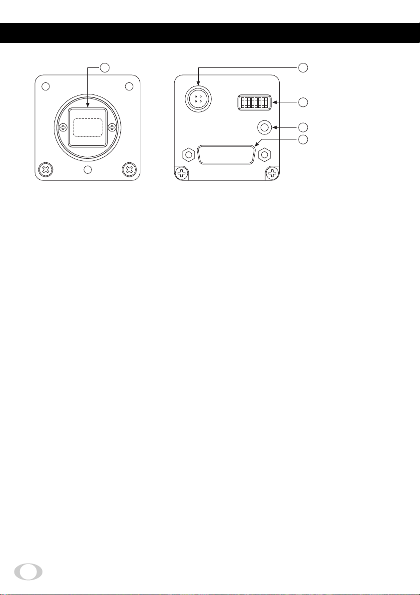
3. CAMERA PARTS AND FUNCTIONS
1
Picture-shooting area
DC IN 12V
MODE SELECT
GAIN
DIGITAL
2
DC IN 12V terminal
3
MODE SELECT
switch
4
GAIN control volume
5
DIGITAL terminal
[Front] [Rear]
Picture-shooting area
11
1
11
The protection cap is attached on the lens mount portion. After removing the cap, mount
the lens. Be careful not to scratch or touch the optical area.
DC IN 12V terminal
22
2
22
Accept a DC power input (12V).
MODE SELECT switch
33
3
33
Selects the gain mode (OFF/ON).
Selects the synchronizing output signal (HD, VD/LEN, FEN).
Selects the operation mode.
Selects the electric shutter exposure time.
Selects the partial scanning mode.
GAIN control volume
44
4
44
Adjusts the video signal gain when the gain mode is set to ON with the MODE SELECT
switch
DIGITAL terminal
55
5
55
33
3
33
.
IK-SX1L: Outputs the EIA RS-644 LVDS 8-bit digital signal. Enters a trigger signal.
IK-SX1: Outputs the Camera Link signal (8-bit digital signal). Enters a trigger signal.
6
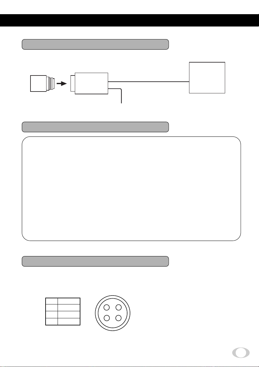
4. CONNECTIONS
4.1. Standard Connection
Image processor
Lens
IK-SX1L
IK-SX1
DC power supply
Camera cable
(option)
DC IN 12V
4.2. Cautions on Connection
• When connecting the camera cables, be sure to turn off the camera and the other
equipment connected.
• The lens for high resolution is recommended.
When using another lens, the best camera performance of this camera may not be
obtained.
(For example, low resolution may occur, and flare, ghost or shading may occur)
• For DC power supply connecting to DC IN 12V terminal, use UL listed and/or CSA
approved ungrounding type AC adaptor with the specifications described below.
Power supply voltage: DC12V±10%
Current rating: More than 830 mA, Less than 2.5A
Ripple voltage: Less than 50 mV(p–p)
Connector: HR10A–7P–4S by HIROSE electronics Co. Ltd Pins 1, 2: +12V
Pins 3, 4: GND
4.3. Connector Pin Assignments
<IK-SX1L, IK-SX1>
DC IN 12V
1
+12V
2
+12V
3
GND
4
GND
Hirose Electronics Co. Ltd. HR10A-7P-4PB
1
234
7
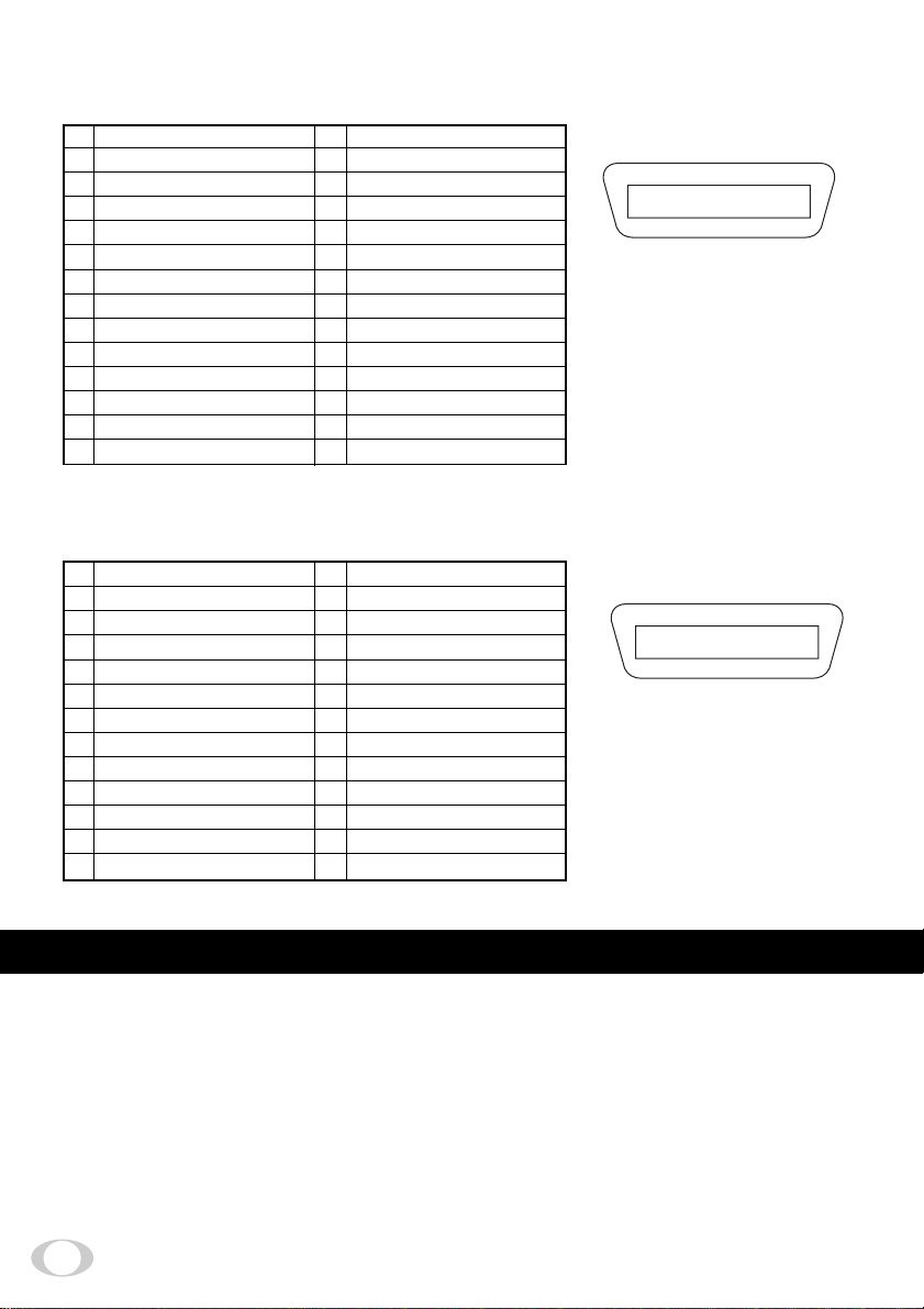
<IK-SX1L>
DIGITAL
1
+D0 (Video Data (LSB))
2
+D1 (Video Data)
3
+D2 (Video Data)
4
+D3 (Video Data)
5
+D4 (Video Data)
6
+D5 (Video Data)
7
+D6 (Video Data)
8
+D7 (Video Data (MSB))
9
+VD/+FEN
10
+HD/+LEN
11
+PCK (Pixel clock)
12
T rigger in (Trigger input)
13
CC3 (Partial Scanning setting)
14
GND
<IK-SX1>
DIGITAL
1
GND
2
–X0
3
–X1
4
–X2
5
–Xclk
6
–X4
7
NC
8
NC
9
–CC1 (Trigger input)
10
+CC2 (Partial Scanning setting)
11
–CC3 (Partial Scanning setting)
12
+CC4 (Partial Scanning setting)
13
GND
15
–D0 (Video Data (LSB))
16
–D1 (Video Data)
17
–D2 (Video Data)
18
–D3 (Video Data)
19
–D4 (Video Data)
20
–D5 (Video Data)
21
–D6 (Video Data)
22
–D7 (Video Data (MSB))
23
-VD/–FEN
24
-HD/–LEN
25
–PCK (Pixel clock)
26
CC2 (Partial Scanning setting)
27
CC4 (Partial Scanning setting)
28
GND
14
GND
15
+X0
16
+X1
17
+X2
18
+Xclk
19
+X4
20
NC
21
NC
22
+CC1 (Trigger input)
23
–CC2 (Partial Scanning setting)
24
+CC3 (Partial Scanning setting)
25
–CC4 (Partial Scanning setting)
26
GND
114
1528
Hirose Electronics Co. Ltd.
HR10A-28S
113
1426
3M
10226-1210
5. OPERATION
Referring to the item ”4. CONNECTION”, connect each equipment correctly.
11
1
11
Turn on the connected equipment and the camera.
22
2
22
Pointing the lens at the object, operate the lens iris adjustment, focus adjustment, etc.
33
3
33
Set the necessary mode by referring to “6. Setting”.
44
4
44
8

6. Setting
MODE SELECT switch
No. 1: Gain ON/OFF
No. 2: Synchronizing signal selection
ON
12345 67890
No. 3: Mode setting
No. 4: Mode setting
No. 5: Mode setting
No. 6: Electric shutter speed
No. 7: Electric shutter speed
No. 8: Electric shutter speed
No. 9: Partial scanning area
No. 10:Partial scanning area
6.1 Gain switch
Use this switch when the image is dark even if the lens iris is fully opened. When the gain
ON is set, adjust the video signal level with the gain control volume on the rear panel.
Mode
Gain OFF
Gain ON
6.2
Synchronizing mode selector switch
This selects the DIGITAL terminal synchronizing signals output.
(–3 to 12dB variable with the control volume)
No.1
OFF
ON
Mode
HD/VD
LEN/FEN
6.3 Mode setting switch
This sets the operation mode.
Mode
Internal synchronization
1-pulse trigger
Pulse width trigger
Internal synchronization draft mode
Internal synchronization partial scanning*
1-pulse trigger partial scanning
Pulse width trigger partial scanning
Internal synchronization partial scanning*
* Same mode
No.3
OFF
OFF
OFF
OFF
ON
ON
ON
ON
No.2
OFF
ON
No.4
OFF
OFF
ON
ON
OFF
OFF
ON
ON
No.5
OFF
ON
OFF
ON
OFF
ON
OFF
ON
9

6.4 Electric shutter speed switch
This sets the electric shutter speed and the exposure time for the 1-pulse trigger.
Electric shutter speed
1/15
1/100
1/500
1/1000
1/2000
1/4000
1/10000
1/50000
No.6
OFF
OFF
OFF
OFF
ON
ON
ON
ON
No.7
OFF
OFF
ON
ON
OFF
OFF
ON
ON
6.5 Partial scanning switch
This sets the partial scanning area.
(Partial scanning can also be set from the DIGITAL terminal on the rear panel.)
Operation mode
Scanning area 1/15 (70 lines, 60 fps)
Scanning area 1/2.6 (400 lines, 30 fps)
Scanning area
Scanning area
Setting from the DIGITAL terminal
(No.9 and No.0 of the MODE SELECT switch become ineffective. )
Switch No. 3 on
the rear panel
OFF
OFF
OFF
OFF
OFF
*: Don’t care. (Either L or H is OK.)
1/2 (560 lines, 24 fps)
2/3 (700 lines, 20 fps)
DIGITAL
terminal CC2
H
H
H
H
L
DIGITAL
terminal CC3
No.9
OFF
OFF
ON
ON
DIGITAL
terminal CC4
H
H
L
L
*
H
L
H
L
*
No.0
OFF
ON
OFF
ON
Operation mode
Scanning area 1/15 (70 lines, 60 fps)
Scanning area 1/2.6 (400 lines, 30 fps)
Scanning area 1/2 (560 lines, 24 fps)
Scanning area 2/3 (700 lines, 20 fps)
Partial scanning OFF
No.8
OFF
ON
OFF
ON
OFF
ON
OFF
ON
10

7. Operation mode
7.1 Internal synchronization
Horizontal synchronization: 15.998 kHz (28.63636 MHz x 1790 clocks)
Vertical synchronization: 15 fps (14.98 Hz = 28.63636 MHz x 1790 clocks x 1068 lines)
Output signal: Video data, pixel clock, FEN/VD, LEN/HD
Video data
(video period image)
HD
VD
FEN
LEN
7.2
Internal synchronization draft mode
When the draft mode is set, the frame rate can be increased by thinning out the image
when outputting.
Horizontal synchronization: 15.998 kHz
Vertical synchronization: 60 fps
Output signal: Video data, pixel clock, FEN/VD, LEN/HD
Video data
(video period image)
HD
VD
FEN
LEN
11

Draft mode OFF
All pixels are independently read out.
Draft mode ON
Pixels are thinned out and read out.
(Only the white pixel is read out.)
Output
7.3
Internal synchronization partial readout
Output
When the partial scanning is set, the frame rate can be increased by decreasing the number of output lines. The number of settable output lines is 70/400/560/700 lines. For the
detail, refer to “8. Partial Scanning”.
Horizontal synchronization: 15.998 kHz (28.63636 MHz x 1790 clocks)
Output signal: Video data, pixel clock, FEN/VD, LEN/HD
Video data
(video period image)
HD
VD
FEN
LEN
12

7.4 1-pulse trigger
Exposure starts by the trigger signal input to the DIGIT AL terminal, and outputs a 1-frame
image. The shutter speed (exposure period) is set with the MODE SELECT switch No. 6 No. 8 on the rear panel.
Input signal: Trigger
Output signal: Video data, pixel clock, FEN/VD, LEN/HD
Trigger
Video data
(video period image)
HD
VD
FEN
LEN
Exposure period
7.5 1-pulse trigger partial readout
This is the mode for partial scanning by the 1-pulse trigger operation.
Input signal: Trigger
Output signal: Video data, pixel clock, FEN/VD, LEN/HD
Trigger
Video data
(video period image)
HD
Exposure period
VD
FEN
LEN
13

7.6 Pulse width trigger
This is the mode to set the exposure period by the pulse width of the trigger signal applied to the DIGITAL terminal. This accumulates electric charge taking the trigger signal
“L” period as exposure time, and developes a 1-frame image. The trigger signal minimum pulse width (“L” period) is 20µs (1/50000s).
Input signal: Trigger
Output signal: Video data, pixel clock, FEN/VD, LEN/HD
Trigger
Video data
(video period image)
HD
VD
FEN
LEN
Exposure period
7.7 Pulse width trigger partial readout
This is the mode for partial scanning by the pulse width trigger operation.
Input signal: Trigger
Output signal: Video data, pixel clock, FEN/VD, LEN/HD
Trigger
Video data
(video period image)
HD
Exposure period
14
VD
FEN
LEN

8. Partial Scanning
The set number of vertical lines is partially scanning, and the frame rate can be increased.
8.1
Scanning area 1/15
(70 lines, 60 fps)
8.2
Scanning area
1/2.6 (400 lines, 30 fps)
8.3
Scanning area 1/2
(560 lines, 24 fps)
70 lines
560 lines
8.4
Scanning area
(700 lines, 20 fps)
400 lines
2/3
700 lines
15

9. Timing Chart
9-1 All pixel scanning
V-rate
1
Internal synchronization
VD
FEN
Video output
Video period
9H
8H
1-pulse trigger, pulse width trigger
VD
FEN
Video output
9H
2H
1040H
1068H
Video period
1040H
11H
16

H-rate
2
Video output
HD
LEN
4
The digits indicate the number of clocks.
1 clock = 34.9 ns (28.63636 MHz)
9.2 Draft mode
V-rate
1
VD
FEN
Video output
1H 1H
180
402
Video period
1392
1790
Video period
9H
260H
267H
17

H-rate
2
Video output
HD
LEN
4
180
402
The digits indicate the number of clocks.
1 clock = 34.9 ns (28.63636 MHz)
9.3 Partial scanning
V-rate
1
Internal synchronization
VD
FEN
Video output
9H
1790
Sweep-off period
Video period
1392
Video period
Sweep-off period
18
70 lines readout
400 lines readout
560 lines readout
700 lines readout
99H
66H
50H
36H
70H
400H
560H
700H
98H
65H
49H
35H
Total
276H
540H
668H
780H

1-pulse trigger, pulse width trigger
VD
(internal synchronization
output position)
VD
(output position)
FEN
Video output
3H
H-rate
2
Video output
70 lines readout
400 lines readout
560 lines readout
700 lines readout
HD
LEN
4
The digits indicate the number of clocks.
1 clock = 34.9 ns (28.63636 MHz)
9H
180
402
Sweep-off period
99H
66H
50H
36H
1790
Video period
70H
400H
560H
700H
Video period
1392
Sweep-off period
98H
65H
49H
35H
Total
276H
540H
668H
780H
19

10. TROUBLESHOOTING CHART
Symptoms
No image
• Is power properly supplied?
• Is the lens iris adjusted properly?
• Is the CRT monitor adjusted properly?
• Is the shutter mode set correctly?
11. SPECIFICATIONS
Power supply
Power consumption
Image sensor
(Effective pixels)
Scanning system
Scan frequency
Sensitivity
Lens mount
Ambient temperature
Ambient humidity
Weight
External dimension
Gain
Video output
Electric shutter
Mode
Partial scanning
Sync signal output
External trigger input
Optional parts
DC12 ± 10%
Approx. 1.7W
2/3inch Progressive Scanning CCD
(Horizontal: 1392 pixels, Vertical: 1040 pixels)
Noninterlace
Horizontal: 15.998 kHz, Vertical: 14.98 Hz
F16 600 lx (GAIN OFF)
C mount
32 to 104° F (0 to 40°C)
Less than 90%
Approx. 4.77 oz (135g)
1.73" (W) x 1.73" (H) x 2.05" (D)
(44 (W) x 44 (H) x 52 (D) mm) (except for protruded portion)
ON (-3 to 12 dB), OFF (0 dB)
IK-SX1L: EIA RS-644 LVDS video 8-bit digital output
IK-SX1: Camera link video 8-bit digital output
1/15s, 1/100s, 1/500s, 1/1000s, 1/2000s, 1/4000s,
1/10000s, 1/50000s
Internal synchronization, internal synchronization draft,
internal synchronization partial scanning
1-Pulse trigger, 1-pulse trigger partial scanning
Pulse width trigger, Pulse width trigger partial scanning
Scanning area 1/15 (70 lines, 6 fps)
Scanning area 1/2.6 (400 lines, 30 fps)
Scanning area 1/2 (560 lines, 24 fps)
Scanning area 2/3 (700 lines, 20 fps)
HD, VD/LEN, FEN LVDS format (IK-SX1L)
PCK (28.63636 MHz) LVDS format (IK-SX1L)
TRIGGER; Low level: Less than 0.4V, High level: 3.4 to 5V
EXC-SX03M (cable for IK-SX1L), EXC-SX03A (cable for IKSX1L), EXC-CL05 (cable for IK-SX1), etc.
Possible causes
Camera Link format (IK-SX1)
Camera Link format (IK-SX1)
Negative
More than 20µs pulse width
* Design and specifications are subject to change without notice.
20

12. EXTERIOR VIEW
Dimensions: mm [inch]
44 [1.73"]
22 [0.87"]
44 [1.73"]
35 [1.38"]
35 [1.38"]
10.5 [0.41"]
26 [1.02"]
13 [0.51"]
6 [0.24"]
35 [1.38"]
7 [0.28"]
3-M3 (screw depth 4mm[0.16"])
26 [1.02"]
10.5 [0.41"]
3-M3 (screw depth 4mm[0.16"])
45.5 [1.79"]
23 [0.91"]
59 [2.32"]
28 [1.10"]
45.5 [1.79"]
7.3 [0.29"]
4-M3 (screw depth 4mm[0.16"])
11 [0.43"]
26 [1.02"]
33 [1.30"]
12 [0.47"]
11.57 [0.46"]
12 [0.47"]
DC IN 12V
DC IN 12V
15.9 [0.63"]
12 [0.47"]
DIGITAL
39 [1.54"]
IK-SX1
DIGITAL
IK-SX1L
MODE SELECT
GAIN
MODE SELECT
GAIN
11 [0.43"]
2.5 [0.10"]
21

Memo
22

Memo
23

LIMITED WARRANTY
CCD CAMERA
The Imaging Systems Division of Toshiba America Information Systems, Inc. (“ISD”) makes the following limited warranties with regard to this CCD Camera (“Product”). These limited warranties extend to the Original End-User (“You[r]”).
One (1) Year Limited Warranty of Labor and Parts: ISD warrants that this Product will perform in accordance with
specifications for a period of one (1) year from the date of purchase by the Original End-User. During this one (1) year
period, ISD will repair or replace the Product, if it does not perform as warranted. In order to take advantage of this Limited
Warranty, You must: (a) deliver the Product to an ISD Authorized Service Provider (“ASP”); and (b) pay all transportation
and insurance charges for shipment of the Product to the ASP. ISD reserves the right to substitute factory refurbished parts
in place of those in need of repair.
Instruction Manual (Owner’s Manual): You should read the Instruction Manual (Owners Manual) thoroughly before
operating this Product. Before seeking warranty service, you should check the troubleshooting guide in the Instruction
Manual (Owner’s Manual) and follow the instructions to correct the problem.
Your Responsibilities: This Limited Warranty is subject to the following conditions:
1. You must provide the bill of sale or proof of purchase at the time that warranty service is required.
2. You must notify an ASP within thirty (30) days after You discover that the Product does not perform in accordance with
specifications during the Limited Warranty period.
3. All warranty servicing of this product must be made by an ISD Authorized Service Provider.
4. You must pack the Product in its original carton using the original packing material, then insert the original carton
containing the Product into another carton with additional packing material before shipping the Product to an ASP.
DISCLAIMERS:
ALL OTHER EXPRESS OR IMPLIED WARRANTIES ON THIS PRODUCT, INCLUDING THE IMPLIED WARRANTIES OF MERCHANTABILITY AND FITNESS FOR A PARTICULAR PURPOSE, ARE HEREBY DISCLAIMED. SOME
STATES DO NOT ALLOW THE EXCLUSION OF IMPLIED WARRANTIES OR LIMITATIONS ON HOW LONG AN
IMPLIED WARRANTY LASTS, SO THE ABOVE LIMITATIONS MAY NOT APPLY TO YOU.
IF THIS PRODUCT IS NOT IN GOOD WORKING ORDER AS WARRANTED ABOVE, YOUR SOLE AND EXCLUSIVE REMEDY SHALL BE THE REPAIR OR REPLACEMENT OF THE PRODUCT. IN NO EVENT WILL ISD OR ITS
PARENT COMPANY OR ANY ASP BE LIABLE TO YOU OR ANY THIRD PARTY FOR ANY DAMAGES IN EXCESS OF THE PURCHASE PRICE OF THE PRODUCT. THIS LIMITATION APPLIES TO DAMAGES OF ANY KIND,
INCLUDING ANY DIRECT OR INDIRECT DAMAGES, LOST PROFITS, LOST SAVINGS OR OTHER SPECIAL,
INCIDENTAL, EXEMPLARY OR CONSEQUENTIAL DAMAGES, WHETHER FOR BREACH OF CONTRACT, TORT
OR OTHERWISE, OR WHETHER ARISING OUT OF THE USE OF OR INABILITY TO USE SUCH PRODUCT, EVEN
IF TAIS, ITS PARENT COMPANY, OR AN ASP HAS BEEN ADVISED OF THE POSSIBILITY OF SUCH DAMAGES
OR OF ANY CLAIM BY ANY OTHER PARTY. SOME STATES DO NOT ALLOW THE EXCLUSION OR LIMITATION
OF INCIDENTAL OR CONSEQUENTIAL DAMAGES FOR SOME PRODUCTS, SO THE ABOVE LIMITATIONS OR
EXCLUSIONS MAY NOT APPLY TO YOU.
THIS WARRANTY GIVES YOU SPECIFIC LEGAL RIGHTS, AND YOU MAY ALSO HAVE OTHER RIGHTS WHICH
MAY VARY FROM STATE TO STATE.
THIS LIMITED WARRANTY SHALL BE VOID IF THE PRODUCT OR PARTS HAVE BEEN SUBJECTED TO MISUSE, ABUSE, ACCIDENT, IMPROPER INSTALLATION, IMPROPER MAINTENANCE, OR USE IN VIOLATION OF
ISD’S WRITTEN INSTRUCTIONS, OR WHERE THE PRODUCT HAS BEEN ALTERED OR MODIFIED WITHOUT
ISD’S PRIOR AUTHORIZATION, OR UPON THE REMOVAL OR ALTERATION OF ISD’S FACTORY SERIAL NUMBER. LABOR SERVICE CHARGES FOR PRODUCT INSTALLATION, SET UP AND ADJUSTMENT OF CONTROLS
ARE NOT COVERED BY THIS LIMITED WARRANTY.
How to Obtain Warranty Service — Step-By-Step Procedures: To obtain warranty service, You should:
1. Contact an ASP for warranty service within thirty (30) days after the Product fails to comply with specifications.
2. Arrange for shipment of the Product to an ASP
3. Securely pack the Product as described above, insure the carton, and include a letter explaining the problem and a
copy of the bill of sale or proof of purchase.
4. Prepay all transportation and insurance costs.
Questions? If you have any questions, please check ISD’s website or send an e-mail as follows:
No person, agent, distributor, dealer, authorized service provider, or company is authorized to change, modify, or extend the
terms of this Limited Warranty in any manner whatsoever. The time within which an action must be commenced to enforce
any obligation of ISD arising under this Limited Warranty or under any statute, or law of the United States or any state
thereof, is hereby limited to one (1) year from the date You discover or should have discovered the problem. This limitation
does not apply to implied warranties arising under state law. Some states do not permit limitation of the time within which
You may bring an action beyond the limits provided by state law, so the above provision may not apply to You. This Limited
Warranty gives You specific legal rights and You may also have other rights which vary from state to state.
Website: http://www.toshiba.com/taisisd/indmed
E-mail: CCTVtech.support@tais.toshiba.com
TOSHIBA AMERICA INFORMATION SYSTEMS, INC.
Imaging Systems Division
9740 Irvine Boulevard, Irvine, CA 92618-1697
Service Department: (949) 461-4989 & 4992
24
 Loading...