

Page 1
TOSHIBA
INSTRUCTION MANUAL
CCD CAMERA
IK-M41F2/IK-M41R2/ IK-C41F2
WARNING
This is a Class A of EN55022 product. In a domestic environment this product may cause radio
interference in which case the user may be required to take adequate measures.
INFORMATION
This equipment has been tested and found to comply with the limits for a Class A digital device,
pursuant to Part 15 of the FCC Rules. These limits are designed to provide reasonable protection
against harmful interference when the equipment is operated in a commercial environment.
This equipment generates, uses, and can radiate radio frequency energy and, if not installed and
used in accordance with the instruction manual, may cause harmful interference to radio com
munications. Operation of this equipment in a residential area Is likely to cause harmful interfer
ence in which case the user will be required to correct the interference at his own expense.
USER-INSTALLER CAUTION: Your authority to operate this FCC verified equipment could be voided
if you make changes or modifications not expressly approved by the party responsible for compllance to Part 15 of the FCC rules.
For Customer Use
Enter below the Serial No.
which is located on the
bottom of the cabinet. Re
tain this information for fu
ture reference.
Model No.: IK-M41F2/
IK-M41R2/
IK-C41F2
Serial No.:
This Class A digital apparatus complies with Canadian ICES-003.
Cet appareil numérique de la classe A est comforme à la norme NMB-003 du Canada.
Page 2

Safety precautions
Read the following safety precautions carefully before using the product. These instructions
contain valuable information on safe and proper use that will prevent harm and damage to
the operator and other persons. Make sure that you fully understand the following details
(indications, graphic symbols) before proceeding to the main descriptions in this manual.
Indication definitions
Indication
This indicates that ignoring this
A
Warning
A
Caution
*2: Physical damage means extended harm to
label and/or misoperation of the
product may cause serious per
sonal injury or even death.
This indicates that ignoring this
label and/or misoperation of the
product may cause personal in
jury*^ and/or material damage*^
*1: Bodily injury means injuries, burns and
electric shock which does not require hos-
pitalization or prolonged treatment.
home, household effects.
Meaning
/j\ Warning
Do not use the product when abnormality occurs.
The use in the abnormality status such as emitting smoke from the product, smelling
O
burning, being damaged by drop, invasion of foreign objects inside the product, etc.
, may cause fire and/or electric shock. Be always sure to disconnect the power plug
from the electrical outlet (socket) at once and contact your dealer.
Do not install the product where splashing of water may occur, such as outdoor, a
bathroom, etc.
This may cause fire and/or electric shock.
Graphic symbol definitions
Symbol
<S)
o
A
Indicates a prohibited action that
must not be carried out. The ac
tual prohibited action is indicated
in the symbol or nearby graphi
cally or described in text.
Indicates a mandatory action that
must be carried out surely. The
actual mandatory action is indi
cated in the symbol or nearby
graphically or described in text.
Indicates an action required cau
tion. The actual action required
caution Is indicated in the symbol
or nearby graphically or described
in text.
Meaning
O
<S)-
Do not repair, disassemble and/or modify by yourself.
This may cause fire and/or electric shock. Be always sure to contact your dealer for
internal repair, check and cleaning of the product.
Keep the rated voltage for the product.
The use of power supply voltage except for its rated voltage may cause fire and/or
electrical shock. Please refer to 2"Connections".
Do not put a vessel(s) filled with a liquid (flower vase, etc.).
If a liquid enters the product, a fire and/or electric shock may occur.
Do not put the product in an unstable, slanting and/or vibrated place.
Drop and/or fail of the product may cause injury.
Page 3

O’
<S)'
(S'
Keep the followings when installing.
• Do not put the product on a Inflammable material such as carpet or blanket.
• Do not put the product in a narrow space, since the heat generated from the prod
uct may be difficult to emanate.
• Do not put a inflammable material on the product.
If you do not keep above, the heat generated by the product may cause fire.
Do not put the product in direct sunshine and/or high temperature.
The temperature rise inside the product may cause fire.
Do not put the product In a moist or dusty place such as a bathroom, a place close to
a humidifier, etc.
This may cause fire and/or electric shock.
Do not put the product in a moist, soot and/or dusty place such as a kitchen, etc.
Do not put the product where a soot and steam may occur, such as a kitchen, etc., or
in a dusty place. This may cause fire and/or electric shock.
Do not shoot the sun with the lens and do not put the lens in the place exposed to an
intensive light, such as the sunshine, etc.
Focusing of the light may cause injury of eye and/or fire.
Do not put the product in your mouse and do not swallow it.
This may cause suffocation and/or injury.
Ask your dealer to perform a periodical check and internal cleaning.
Dust inside the product may cause fire and/or trouble. For check and cleaning cost,
please consult your dealer.
Maintenance
Do not use benzine, alcohol and/or thinner, etc. for cleaning. If you use it, painting or
indication on the product may be worn off or deteriorated.
1. Cautions on use
• Handle the unit carefully. — Do not drop or give a strong shock or vibration. This may
cause trouble. Handling a camera cable roughly may cause the break of cable.
• Do not shoot intense light. — if there is an intense light at a location on the screen such as
a spot light, blooming and smearing may occur. Do not aim the camera at the sun. If an
intense light enters, vertical strips may appear on the screen. However, this is not trouble.
• Install the camera In a location free from noise. — If the camera or the cables are located
near power utility lines or a TV, undesirable noise may appear on the screen, in such a
case, try to change the location of the camera or the cable wiring.
• Handling of the camera head and protection cap. — Keep the camera head and the protec
tion cover away from children. Children may put them into mouth or swallow them acci
dentally. The protection cover protects the image sensing plane when the lens is removed
from the camera head, do not throw away.
• When not using the camera for a long time. — Stop the power supply for safety.
• When cleaning the camera — Be sure to turn off the power and wipe with a dry cloth. If
necessary, gently wipe with a cloth impregnated with thinned detergent. Do not use ben
zine, alcohol, thinner, etc. If used, coating and printed letters may be discolord and deterio
rated. When cleaning the lens, use s lens cleaning paper, etc.
Page 4

TABLE OF CONTENTS
1. CAMERA PARTS AND FUNCTIONS.................................................................5
2. CONNECTIONS..................................................................................................8
3. SIGNAL INPUT/OUTPUT
4. MODE SETTING AND AUXILIARY FUNCTION
5. INTERNAL SYNC.............................................................................................16
6. EXTERNAL SYNC. BY C-SYNC / VS / VBS
7. EXTERNAL SYNC. BY HD, VD........................................................................17
8. RESET/RESTART MODE.................................................................................19
9. ONE-PULSE TRIGGER MODE
10. SHUTTER SPEED SETTING AT INTERVALS OF 1H.....................................22
11. LIST OF VIDEO OUT MODE SETTING
12. DC POWER SUPPLY AND POWER CONNECTION.......................................26
13. TROUBLESHOOTING CHART
14. CONFIGURATION............................................................................................27
15. OPTIONS.......................................................................................................... 28
16. SPECIFICATIONS............................................................................................29
17. EXTERIOR VIEW
.................................................................................
..............................................
....................................................
........................................................................
...........................................................
........................................................................
.............................................................................................
10
12
16
20
24
27
31
Page 5

1. CAMERA PARTS AND FUNCTIONS
IK-C41F2
Hexagon socket
headbolts
Page 6
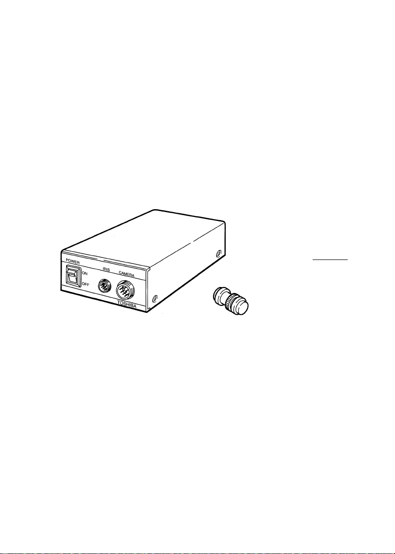
Camera control unit (CCU)
IRIS Terminal
Page 7

0 Iris Ring (The lens is option.)
(0 Focus Ring
® Image Pick-up (CCD)
© Focus Lock Ring
® Portion for Camera Holder
© Camera Cable Terminal
© Camera Cable (Option)
® Camera Cable Connector
® Camera Holder
® Lens Mount
® Picture shooting area
® Camera Head Securing Screw
® Camera connector
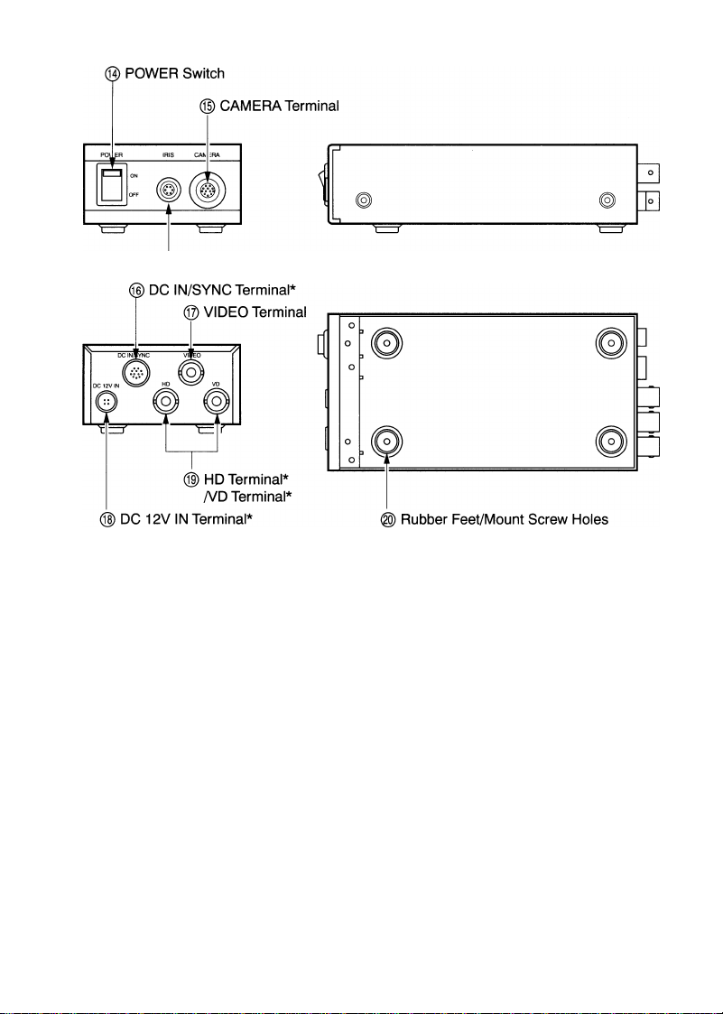
® POWER Switch
® CAMERA Terminal
® DC IN/SYNC Terminal*
® VIDEO Terminal
@ DC 12V IN Terminal*
® HD Terminal*/VD Terminal*
® Rubber Feet/Mount Screw
Holes
To get appropriate iris, the aperture size is adjusted by
turning this ring.
The focus is adjusted by turning this ring.
Should be kept from dirt, dust, finger-print, etc.
When the focus lock ring is set, movement of the focus
ing ring becomes heavy.
This portion is held by the camera holder.
The 'CAM' side of the camera cable is connected to this
terminal.
To connect the camera head and the camera control unit
(CCU).Refer to 'OPTIONAL CAMERA CABLES/LENSES'.
To be connected to 6 Camera Cable Terminal on the rear
of the camera head and to 15 CAMERA Terminal of the
CCU. Before connection, confirm the side ('CAM' or
'CCU') of the cable.
When installing the camera head to a tripod or the like,
use the camera holder.
Used to mount the C mount lens.
Be always sure to keep off dust, finger prints, etc.
Used to mount the camera head
Connector to CAMERA terminal of camera control unit
To turn on/off the power.
The 'CCU' side of the camera cable is connected.
This terminal is to be used for VIDEO output. External
Sync, input.
Note: When the signal is input/output through this DC
IN/SYNC terminal, 'DC 12V IN'/'HD, VD' terminals
(* marked) are not connected.
This output terminal is to be connected to Monitor or
VCR video-in terminal. (BNC pin)
The DC power (12V) is connected to this terminal.
These terminals are used for sync, with external control unit.
Remove four rubber feet, and fix the CCU with screws
(MStype). The screw must not protrude more than 5mm
beyond the inside surfaces of the CCU.
Page 8
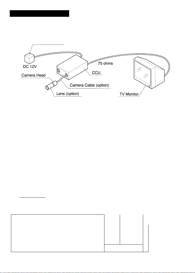
2. CONNECTIONS
IK-M41 P2,IK-M41R2
DC Power Supply
-IMPORTANT------------------------------------------------------------------------------------------------------
Before connecting or disconnecting camera cable, be sure to turn the power OFF.
Otheriwise, the camera head may be damaged, which will void warranty.
1. Detach the cap from the camera head, and attach an optional lens.
2. Connect the camera cable terminal of the camera head and the CAMERA terminal of
the ecu with the camera cable (option). (Refer to NOTE 1.)
3. Connect the VIDEO terminal of the CCU and VIDEO IN terminal of the TV monitor with
a video cable. (Refer to NOTE 2.)
4. Connect the cord from the DC power supply to the DC 12V IN terminal of the CCU.
(Refer to NOTE 3.)
5. Adjust the Iris/Focus rings of the lens (option) to get appropriate image.
IK-C41P2
1. Mount the lens on the camera and make the wiring between devices.
Available lens
Use a C-mount lens with its protruded dimensions (L) from the mounting surface less
than 7.0 mm.
— NOTE: ---------------------------------------------------------
• When the lens quantity exceeds 500g, do
not fix the lens by using its camera head
securing screw holes but keep the lens on
its lens side.
• The camera is not equipped with the back
focus adjustment mechanism.
Lens
C-mount
U
/
Less then 7.0mm
L
Page 9
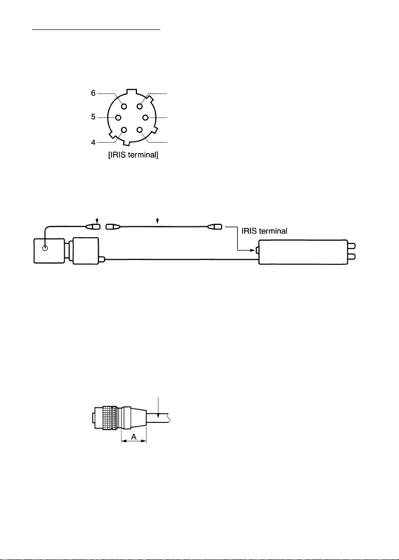
When using an automatic iris lens
When using a EE lens of video feed back type, since the EE video signal develops at the
6P terminal "IRIS" located on the front side of the camera, the signal is sent to the EE
lens. When using an iris extension cable (EXC-C2E, etc.), use HR10A-7P-4P (Hirose
Electronics Co. Ltd.) for the connector on the lens side.
(GND)
EE power
supply +12V
(max. 50 mA)
EE lens
NOTE: 1.
NC
1 NC
EE video signal
0.8±0.15V(p-p)
3 GND
When short-circuiting the EE
power supply accidentally, the
fuse inside the camera is cut
and the EE power supply does
not come out. Be always sure to
take care of the wiring.
- Hirose Electronics Co. Ltd. HR10A-7P-4P
(Connection 1: -I-12V, 2: GND, 3: EE video signal, 4: GND)
;■
----
Iris extension cable (EXC-C2E, etc.)
Camera control unit
Make sure power switches of the CCD and TV monitor are at OFF position.
Securely tighten the connectors of camera cable.
2.
When using VCR, connect the video cable from the CCU to the VIDEO IN termi
nal of VCR.
Read the operation manual before making connections.
3.
Precautions for connections (HR10A-7P-4S).
Plugging
Unplugging
Cable
To connect the cable of the DC power
supply, hold A position of the plug,
and match the plug guide to the re
ceptacle guide so that connection can
be done smoothly.
Cable
To detach the plug, hold B portion of
the plug and pull it straightforward so
that the plug can be detached easily.
9
Page 10
3. SIGNAL INPUT/OUTPUT
|1| Ceitditioii o§ IxlWMii Sync, laput
1.HD
2.VD
3. C-SYNC 3.0±1.5Vp-p • Negative polarity • 75Q unbalanced
4. VS/VBS
5. RR. VD
6. TRIGGER
NOTE: In case of VD, C-SYNC,
3.0±1.5Vp-p • Negative polarity • 75Q unbalanced
5.0±0.5Vp-p • Negative polarity • TTL level
3.0±1.5Vp-p • Negative polarity • 75Q unbalanced
5.0±0.5Vp-p • Negative polarity • TTL level
5.0±0.5Vp-p • Negative polarity • TTL level
0.3±0.1Vp-p • 75Q unbalanced
3.0±1.5Vp-p • Negative polarity • 75Q unbalanced
5.0±0.5Vp-p • Negative polarity • TTL level
3.0±1.5Vp-p • Negative polarity • 75Q unbalanced
5.0±0.5Vp-p • Negative polarity • TTL level
VSA/BS and RR. VD, use the connector for DC IN/SYNC termi-
nal or VD terminal and
External sync, frequency range: Within ±1.0% against NTSC standards
input a signal selected dependent on the mode in use.
6.0\is - 10.0p.s
3H to 9H
EIA-170A standards
EIA-170A standards
3H to 9H
3H to 9H
[ (3) Specifications of Ixternal Owtput Sigwgl ]
1. VIDEO
2. VIDEO INDEX
3. HD
4. VD
5. CLOCK
When HD and VD, common with HD IN and VD IN, are used for inputting, they cannot be
used for outputting. (Input/output can be selected by changing the internal connector.
Input: P304, Output: P305) CLOCK can be output by shorting the inner land.
I.OVp-p • 75Q unbalanced
5.0±0.5Vp-p • Positive polarity • Load impedance more than 10KQ
5.0±0.5Vp-p • Negative polarity • Load impedance more than 10KQ
5.0±0.5Vp-p • Negative polarity • Load impedance more than 10KQ
4.0±1.5Vp-p • 14.31813 MHz • Load impedance more than 1KQ
Inner land for CLOCK
- Connectors
10
CKOUT
Inside of the camera
MAIN board
Output Input
Page 11

(3) 12 Pin Connecter (DC IN/SYNC terminal)
In case the signal is input/output directly from DC IN/SYNC terminal, connect as follows.
[ DC IN/SYNC terminal]
1 9
Type of connector to be used with DC IN/SYNC
terminal: HIROSE HR10A-10P-12S
External Sync. Mode
Pin No.
2* Power +12V Power +12V Power +12V
6*
7*
10 VIDEO INDEX (output)
11 TRIGGER (input)
12
VS/VBS/C-SYNC
Power GND Power GND Power GND
VIDEO (GND) VIDEO (GND)
VIDEO (Signal) VIDEO (Signal) VIDEO (Signal)
HD input (GND) HD input (GND)
HD input (Signal) HD input (Signal)
VSA/BS/C-SYNC input
(Signal)
CLK output (GND)
CLK output (Signal)
VSA/BS/C-SYNC input
(GND)
VD input (Signal)
CLK output (GND) CLK output (GND)
CLK output (Signal) CLK output (Signal)
VD input (GND) VD input (GND)
HD, VD
RESET RESTART/
One-pulse Trigger
VIDEO (GND)
VD input (Signal)
CLOCK OUT requires to short the inner land.
-IMPORTANT
The one marked with * is parallely connected to HD, VD, and DC 12V IN terminals.
Input/output of the signal should be carried out from either one terminal only. (Do not
make connection simultaneously.)
11
Page 12

4. MODE SETTING AND AUXILIARY FUNCTION
The auxiliary function is set with the built-in switch of the unit. In order to change the
setting, remove the cover by detaching 4 screws on the side of the CCU.
Switch layout (cover removed)
-IMPORTANT
When operating the internal switch or using the soldering iron, the built-in circuit of
the unit is exposed, which may hazardous condition of breaking static electricity.
In order to prevent the static electricity breaking, make sure to duly observe the fol
lowing items upon the operation.
© Do not touch any parts and boards other than the switch required to be operated.
@ Do not wear the cloth which is likely to cause static electricity, such as nylon, rubber or
the like. Make sure to put on cotton gloves when carrying out the operation.
® Put on the earth band with the arm for earthing. If the earth band is not available,
touch GND of BNC connector pin before starting the operation.
® Cover the working table with the conductive sheet for earthing.
® Earth GND of the BNC connector pin of the set.
12
Page 13

Gamma correction change-over:
Set S310 to select gamma correction amount to 0.45 or 1.
Gain-up mode:
Set S311 at OFF for normal mode (OdB), and ON for gain-up mode. The gain up amount is
adjustable
maximum to +12dB by setting RV33.
Reset/Restart mode external sync, switch:
In case of RR VD external sync, mode, set S314 at R. RVD. If not, set S314 at NORM.
Input impedance selector switch:
In case the input Impedance of external sync, input signal (VSA/BS/C-SYNCA/D, HD/RR.VD)
is set to 75ii, set S312 at ON (75Q terminated). In case it set to ^KQ, set S312 at OFF (TTL
input).
In case the trigger input Impedance is set to 75i2, set S313 at ON (75Q terminated).
In case it is set to 1 KQ, set S313 at OFF (TTL input).
Flickerless:
Setting S305 to 1/100 allows to reduce the occurrence of flickering phenomenon in the
region with power frequency of 50Hz (The picture flickers under the illumination pro
duced by electric discharge lamps). Inoperative at One-pulse trigger mode and reset/restart mode.
Automatic Electronic Shutter:
Set S305 at ON, and set S306 at AUTO. RV31 is used for fine tuning of the video level.
The camera is designed to automatically control the exposure time ranging from 1/60 to
1/50000 s. in
order to change in luminous energy of the subject.
Inoperative at One-pulse trigger mode and reset/restart mode.
Electronic shutter:
The shutter speed may be set by using either direct setting with a rotary switch, or binary
setting with dip switch. The direct setting with the rotary switch is used for setting at any
mode. The binary setting with the dip switch is used for setting the shutter speed at every
1H (1H=63.5^is) at One-pulse trigger mode.
© Direct setting with rotary switch (any mode)
Set S305 at ON, and set S306 at MANU. Set the rotary switch S307 at the position
corresponded to the desired shutter speed as shown in the table below.
S307 Position
0, 8,9
1
2
3
4
5
6
7
Shutter speed
1/60S
1/125S
1/250S
1/500S
1/1000s
1/2000S
1/4000S
1/10000s
Binary setting with dip switch (One-pulse trigger mode) Refer to 'SHUTTER SPEED
SETTING AT INTERVALS OF 1H'.
13
Page 14

One-pulse trigger mode setting, Reset/Restart mode setting for trigger input:
The rotary switch S309 is used for the mode setting. Before setting the mode, make sure
to turn the powerof the camera off.
S309 Position
0, 1,2, 3, 8,9
4
5 Trigger input, RR. SYNC-RESET
6 One-pulse trigger, SYNC-NONRESET
7
Set internal sync., external sync. (VS/C-SYNC, HD/VD) and reset/restart (HD, RR.VD input)
at NORMAL mode.
Normal mode
One-pulse trigger, SYNC-RESET
Trigger input, RR. SYNC-NONRESET
Mode
Field/Frame accumulation mode:
Set No.1 of S308 to select accumulation/read out mode of CCD output signal.
ON: Frame accumulation
OFF; Field accumulation
Set No.1 of S308 to select field accumulation interlaced mode/frame accumulation inter
laced mode at trigger input mode of reset/restart.
ON: Frame accumulation interlaced mode
OFF: Field accumulation interlaced mode
Output field designation:
The video output field can be designated by selecting switches No.2 and No.3 of S308.
The setting mode changes depending on the mode.
• Internal sync.
Video output field can be designated. Non-interlaced video image: 1 field (1V)=262H
• Reset/Restart trigger input mode, SYNC-RESET mode
Output the field designated by selecting the switches No.2 and No.3 of S308.
• One-pulse trigger SYNC-RESET mode
Output the field designated by selecting the switches No.2 and No.3 of S308.
• Other mode
Output field cannot be designated. Turn the switches No.2 and No.3 of S308 off.
14
S308
No.2
ON
ON ON
OFF
OFF
No.3
OFF ODD field
OFF
ON
Video output field
EVEN field
Designation OFF
Designation OFF
Page 15

CLOCK output:
Shorting the land of MAIN board will allow the clock to be output from 9 pin (signal) and
8 pin (GND) of DCIN/SYNC terminal (12 pin connector) on the rear.
The clock output is 14.31818 MHz ± 50ppm.
VIDEO OUT C-coupling, DC direct connection output switching
The video out signal develops from both pins 4 (signal), 3 (GND) of the DC IN/SYNC termi
nal located on the rear side of the camera and the video terminal (BNC connector).
Setting No. 9 and No. 10 of the S308 mode switch can select either the DC direct connec
tion output (the video blanking signal except SYNC is fixed to GND.) or the C-coupling
output for the video output signal.
S308
No. 9 No. 10 VIDEO (BNC connection) DC IN/SYNC (pin 12)
OFF OFF
OFF ON
ON OFF
ON ON
C-coupling output
DC direct connection output
C-coupling output
DC direct connection output
VIDEO output
C-coupling output
C-coupling output
DC direct connection output
DC direct connection output
15
Page 16

5. INTERNAL SYNC.
At internal sync, mode, the video output field can be designated as well as outputting
video signals of NTSC normally Interlaced at 262.5H. The video output field can be des
ignated by selecting the switches No.2 and No.3 of S308 as shown in the table below.
Output field
OFF
ODD
EVEN
Upon designating the output field, the video out sends each designated field which is
non-interlaced (1 field=262H).
S308
No.2
OFF OFF
OFF ON
ON OFF
ON ON
No.3
6. EXTERNAL SYNC. BY C-SYNC/VS/VBS
C-SYNC: Composite-SYNC signal
VS: VIDEO/Composite-SYNC signal
VBS: VIDEO/BURST/Composite-SYNC signal
In order to set external sync, mode with the signal selected from C-SYNC, VS and VBS,
input to VD IN terminal on the rear (BNC connector) or 7 pin (signal) and 12 pin (GND) of
DC IN/SYNC terminal (12 pin connector). No signal is necessary to be input to 5 pin and 6
pin of HD IN terminal (BNC connector) and DC IN/SYNC terminal.
Set S314 to R.R when the external sync. Is carried out by using BBS (BLACK/BURST/
Composite-SYNC) signal.
Set the S314 (R.R MODE switch) and S312 (HD. VD 75Q ON/OFF switch) according to the
input conditions of C-SYNC, VS and VBS as shown in the table below.
Signal
C-SYNC/VSA/BS 0.3±0.15Vp-p, 75Q unbalanced
C-SYNC 3.0±1.5Vp-p, 75Q unbalanced ON NORM
C-SYNC
External sync, frequency range: Within ±1.0% against NTSC standards.
5.0±0.5Vp-p, TTL OFF
Input condition
16
S312
75Q terminated SW
ON
S314
R.R. mode SW
NORM
NORM
Page 17

EXTERNAL SYNC. BY HD, VD
[ iwwiiiMil» gnd «wiicli setting for HP, VP
Input terminals
HD 6 pin (signal) and 5 pin (GND) of HD IN terminal (BNC connector) or DC IN/SYNC
terminal (12 pin connector)
VD 7 pin (signal) and 12 pin (GND) of VD IN terminal (BNC connector) or DC IN/SYNC
terminal (12 pin connector)
Switch setting
Signal Input condition S312
75Q terminated On/Off SW
HD, VD
|S) Phos* and frequency cendMens of HD, VD
Phase condition
3.0±1.5Vp-p, 7bQ unbalanced ON
5.0±0.5Vp-p, TTL level
1/2H (31.8ns)
OFF
1H(63.5^s)
S314
R.R. mode SW
NORM
NORM
HD
VD
ODD FIELD
VD
EVEN FIELD
11 .Ons VD end edge is within this range.
1
'
15.8ns
15.9ns
V L/ wl lU wUv
^ within this r
\/r\ onri orlr
je is
ange.
Frequency condition
HD: 15.734kHz ± 1% (63.56^s ± 1%)
VD: More than 244H (1 H=63.56^is: 1 horizontal scanning period) at intervals of 0.5H.
Standard VD is 262.5H.
17
Page 18

Interlaced/non-interlaced operation may be carried out by changing the input phase con
ditions of HD and VD.
Interlaced operation
The input phases of VD and HD may be arranged to be ODD and EVEN alternately at
every 1 field so that the video output is interlaced. (Normal HD, VD Input)
Non-interlaced operation
The input phases of VD and HD may be arranged to be either ODD or EVEN only for all
the fields so that the video output is not interlaced. The 'non-interlaced' operation
refers to scan the same scanning line at every field. At non-interlaced operation, verti
cal resolutions may be decreased as shown in the table below.
Operation mode
Frame accumulation interlaced mode
Field accumulation interlaced mode
Frame accumulation non-interlaced mode
Field accumulation non-interlaced mode
Resolution
Fine
Very Good
Good
Good
18
Page 19

8. RESET/RESTART
The camera is designed to reset/restart for retrieving information on a single screen at
any desired time. The reset/restart mode has two types, the mode for inputting RR VD
and HD, and the mode for inputting trigger.
(1) RR VD, HD Iniiwt r*««t/i«slart
1 field
RP VD input
U LT
Video output
The above figure shows an example of the frame accumulation interlaced mode. The
required number of RR VD for video output is to be input.
[ (a)frtgfr iw|Mit roset/resHift mode
Trigger pulse input
Video output
Video index output
The above figure shows an example of the frame accumulation interlaced mode. In
putting only 1 trigger pulse may provide the identical image to that obtained at the RR
VD, input reset/restart mode.
----------
U U LJ
19
Page 20

9. ONE-PULSE TRIGGER MODE
The camera is designed to carry out one-pulse trigger for retrieving the information on a
signal screen momentarily at the desired time. The one-pulse mode has two types, SYNC
reset mode and SYNC non-reset mode. At SYNC reset mode, vertical sync, is carried out
by trigger inputting. At SYNC non-reset mode, vertical sync, is not carried out by trigger
inputting.
trigf|*r SYNC f—t modb
Trigger pulse input
u
Exposed period (approx.)
Video output
Video index output
The exposure period starts from the end edge of the trigger pulse and the exposure is
conducted for the period at the predetermined shutter speed. When the exposure is
finished, video image by 1 field is output.
20
Page 21

The exposure period not overlapped with V-SYNC
Trigger pulse input
-------------------
IT
Exposed period
Video output
Video index output
The exposure period not overlapped with V-SYIMC
Trigger pulse input
U LJ
/A
¥
Video output
Video index output
T1 U \J
U LJ
Exposed period
¥
At this mode, the exposure starts after the end edge of the trigger pulse. It is finished
when the period at the predetermined shutter speed elapses. The video signal is out
put upon vertical sync. (V-SYNC) immediately after the end of the exposure. In case
the exposure period overlaps with V-SYNC, the video image will be output from the
next closest V-SYNC.
21
Page 22

10. SHUTTER SPEED SETTING AT INTERVALS OF 1 H
The shutter speed can be set at intervals of 1H (1H=63.5 ^is) only at one-pulse trigger
SYNC reset/non-reset modes. At these modes, the shutter speed can be set in the range
from 262.5H (1/60 s) to OH (1/30000 s). The shutter speed is set with S302. The mode is set
with switches No. 7 and No. 8 of S308. Then S301 is pressed once after confirming the
power is turned ON.
S308 (mode setting)
No. 7 setting: In case of 1/60 (262.5H) to 1/984.3 (16H), set at OFF.
In case of 1/1049.9 (15H) to 1/30000, set at ON.
No. 8 set at ON: When setting the shutter speed at intervals of 1H.
(Turned OFF when direct setting by means of S305, S306 and S307.)
S302 (Shutter speed data)
Set the exposure period (H) (shutter speed) as binary data of 9 bit. Set '0' at ON, and at
OFF with 'No.V side of S302 as LSB and 'No.9' side as MSB. For example, in case the
exposure period is 8H (shutter speed ranging from 1/63.5 x 8 ^is to 1/2000 s.), S302 is set
as below, since the number '8' is rewritten into '000001000' as binary data of 9 bit.
(LSB)
The exposure period A(H) and the shutter speed 1/B (s) can be obtained from the follow
ing equations. The obtained exposure period A(H) is rounded to the nearest integral num
ber.
(MSB)
Not used.
(Be always sure to turn off)
22
Page 23

SITNC •««il modi«
The shutter speed is set to be higher than 1/984.3 s (16H):
Exposure period A(H)=14318180/910 x shutter speed 1/B s.
The shutter speed is set at 1/984.3 s (16H) or lower:
Exposure period A(H)=14318180/910 x shutter speed 1/B s - 10
(a) Ott0»|Wils» triggw SYliC wiotle
Exposure period A(H)=14318180/910 x shutter speed 1/B s.
Examples of setting input data of exposure period
S308
Mode
One-pulse
trigger
SYNCRESET
One-pulse
trigger
SYNC-
NONRESET
Shutter
speed
1/eOs
1/250S
1/1000s 6
1/2000S 8
1/10000s
1/30000S 0
1/eos
1/250S
1/1000s 16
1/2000S 8
1/10000s
1/30000s 0
Input
data
252
262
ON OFF ON
53
ON OFF ON
ON
ON ON ON
1
ON ON ON
ON ON ON
ON
63
ON OFF ON
ON
ON ON ON
1
ON ON ON
ON ON ON
8
MSB S302 LSB
7
OFF ON
OFF
OFF
OFF
ON
9
8
OFF OFF
ON ON
ON ON
ON ON
ON ON
ON ON
ON ON
ON ON
ON ON
ON
ON ON ON
ON
7 6
ON
ON
OFF
OFF
ON
ON
ON
ON
ON
OFF
ON
ON
ON
4
5
OFF OFF OFF
OFF
ON ON OFF
ON
ON
ON
ON ON OFF
OFF OFF
OFF
ON OFF
ON ON ON
ON ON ON
3 2
ON OFF
OFF ON
ON ON
ON ON
OFF
ON ON
ON
ON
ON
OFF
ON
ON
ON
OFF
OFF
ON
ON
ON
ON
1
ON
OFF
ON
ON
OFF
ON
ON
OFF
ON
ON
OFF
ON
23
Page 24

N)
Mode
Internal sync.
C-SYNCA/BSA/S mode
CC
C
HD, VD mode
LU m
HD, RRVD input,
frame accumulation interlaced
HD, RRVD input,
field accumulation interlaced
HD, RRVD input,
non-interlaced
Trigger input SYNC reset,
frame accumulation interlaced
Trigger input SYNC reset,
field accumulation interlaced
Trigger input SYNC reset,
non-interlaced
Trigger input SYNC non-reset, frame accumulation
interlaced, HDA/D: internal sync.
Trigger input SYNC non-reset, frame accumulation
■c
interlaced, HD: External sync.
w
Trigger input SYNC non-reset, frame accumulation
flS
interlaced, VD: External sync.
0)
cr
Trigger input SYNC non-reset, frame accumulation
interlaced, HDA/D: External sync.
Trigger input, SYNC non-reset, non-reset, frame
accumulation inerlaced, C-SYNC/VBS/VS: External sync.
Trigger input SYNC non-reset, field accumulation
interlaced, HDA/D: internal sync.
Trigger input SYNC non-reset, field accumulation
interlaced, HD: External sync.
Trigger input SYNC non-reset, field accumulation
interlaced, VD: External sync.
Trigger input, SYNC non-reset, non-reset, field accumulation
inerlaced, HD/VD: External sync.
Trigger input, SYNC non-reset, non-reset, field accumulation
inerlaced, C-SYNCA/BS/VS: External sync.
Trigger input, SYNC non-reset, non-interlaced,
HD/VD: internal sync.
External
trigger
input
signal
setting
None 0
C-SYNCor
VBS or VS
HD, VD
HD, RRVD
HD, RRVD
HD, RRVD
Trigger
(HD)
Trigger
(HD)
Trigger
(HD)
Trigger
Trigger,
HD
Trigger,
VD
Trigger,
HD, VD
Trigger,
C-SYNC/VBS/VS
Trigger
Trigger,
HD
Trigger,
VD
Trigger,
HD,VD
Trigger,
C-SYNC/VBS/VS
Trigger 7
S309
mode
0
0
0
0
0
5
5
5
7
7
7
7
7
7
7
7
7
7
2 I 3
Field/
Frame
acciimulation
Set
Can be set
Set
OFF OFF
Set
OFF OFF
ON
OFF OFF
OFF OFF
OFF
OFF
OFF OFF
Can be set
ON
Can be set
OFF
Can be set
OFF
Can be set
ON
OFF OFF
ON
OFF OFF
ON
OFF OFF
ON
OFF OFF
ON
Can be set OFF OFF OFF OFF
OFF
OFF OFF OFF OFF OFF OFF
OFF
OFF OFF ON OFF OFF OFF
OFF
OFF OFF OFF OFF OFF OFF OFF
OFF
OFF OFF OFF OFF OFF OFF OFF
OFF
Can be set
OFF
4
5
External
Output
field
Non
SYNC
interlaced
(onlyVD)
OFF OFF
OFF OFF
OFF OFF OFF
OFF OFF OFF OFF
OFF OFF OFF OFF OFF Set with rotary switch S307
OFF
OFF
OFF OFF OFF OFF OFF Set with rotary switch S307
OFF OFF OFF
ON OFF
OFF
OFF OFF
OFF OFF
ON OFF OFF
OFF OFF
OFF OFF OFF
OFF ON OFF OFF OFF
1
S308
6 7 I 8
Shutter at
H.V
Reset
intervals of 1H
OFF OFF
OFF OFF
OFF OFF OFF Set with rotary switch S307
OFF OFF OFF Set with rotary switch S307
OFF OFF OFF Set with rotary switch S307
OFF OFF OFF Set with rotary switch S307
OFF Set with rotary switch S307
OFF Set with rotary switch S307
OFF OFF Set with rotary switch S307
OFF Set with rotary switch S307
OFF OFF
OFF OFF Set with rotary switch S307
OFF OFF Set with rotary switch S307
OFF OFF Set with rotary switch S307
OFF Set with rotary switch S307
OFF Set with rotary switch S307
OFF Set with rotary switch S307
Shutter speed
Set with rotary switch S307
Set with rotary switch S307
Set with rotary switch S307
Set with rotary switch S307
Remarks
Output field is determined by input phase relation
between HD and VD.
Input RRVD as a set of 4 pulses
Input RRVD as a set of 3 pulses
Input RRVD as a set of 2 pulses
Reset/restart by trigger inputting
Reset/restart by trigger inputting
Reset/restart by trigger inputting
Reset/restart by trigger inputting but SYNC is not
reset by trigger inputting
Reset/restart by trigger inputting but SYNC is not
reset by trigger inputting
Reset/restart by trigger inputting but SYNC is not
reset by trigger inputting
Reset/restart by trigger inputting but SYNC is not
reset by trigger inputting
Reset/restart by trigger inputting but SYNC is not
reset by trigger inputting
Reset/restart by trigger inputting but SYNC is not
reset by trigger inputting
Reset/restart by trigger inputting but SYNC is not
reset by trigger inputting
Reset/restart by trigger inputting but SYNC is not
reset by trigger inputting
Reset/restart by trigger inputting but SYNC is not
reset by trigger inputting
Reset/restart by trigger inputting but SYNC is not
reset by trigger inputting
Reset/restart by trigger inputting but SYNC is not
reset by trigger inputting
Page 25

Mode
Trigger input, SYNC non-reset,
non-interlaced, HD: External sync.
Trigger input, SYNC non-reset,
s
non-interlaced, VD: External sync.
w
Trigger input, SYNC non-reset,
ffl
non-interlaced, HD/VD: External sync.
DC
Trigger input, SYNC non-reset,
non-interlaced, C-SYNC/VBS/VS: External sync.
SYNC reset
SYNC reset, HD input
SYNC non-reset,
O)
HDA/D: Internal sync.
O)
SYNC non-reset,
«
HD: External sync.
3
Q.
d>
SYNC non-reset,
C
VD: External sync.
O
SYNC non-reset,
HD/VD: External sync.
SYNC non-reset,
C-SYNCA/BS/VS: External sync.
External
input
signal
Trigger,
HD
Trigger,
VD
Trigger,
HD, VD
Trigger,
C-SYNC/VBS/VS
Trigger
Trigger,
HD
Trigger
Trigger,
HD
Trigger,
VD
Trigger,
HD, VD
Trigger,
C-SYNC/VBS/VS
S309
trigger
mode
setting
7 OFF
7
7
7
4
4
6
6
6
6
6
1
2 I 3
Field/
Output
Frame
field
accumulalion
OFF
OFF
OFF
OFF
OFF
OFF
OFF
Can be set
OFF
OFF Can be set
Can be set
OFF
OFF
OFF
OFF
OFF OFF
OFF
OFF OFF
OFF OFF
(onlyVD)
OFF
OFF
OFF
OFF
OFF
OFF
S308
4
5 6
External
Non
SYNC
interlaced
OFF ON
ON ON OFF
OFF ON OFF
OFF ON
OFF OFF
OFF OFF
OFF OFF OFF
OFF
OFF OFF
ON
OFF OFF
OFF OFF OFF
OFF
OFF OFF
H.V
Reset
OFF OFF
OFF OFF
ON
OFF
7 I 8
Shutter at
intervals of 1H
OFF
OFF
OFF
OFF
OFF
OFF
Can be set
Can be set
Can be set
Can be set
Can be set
Can be set
Can be set
Shutter speed
Set with rotary switch S307
Set with rotary switch S307
Set with rotary switch S307
Set with rotary switch S307
Set with rotary switch S307
Set at intervals of 1H with S302
Set with rotary switch S307
Set at intervals of 1H with S302
Set with rotary switch S307
Set at intervals of 1H with S302
Set with rotary switch S307
Set at intervals of 1H with S302
Set with rotary switch S307
Set at intervals of 1H with S302
Set with rotary switch S307
Set at intervals of 1H with S302
Set with rotary switch S307
Set at intervals of 1H with S302
Remarks
Reset/restart by trigger inputting, but SYNC
is not reset by trigger inputting.
Reset/restart by trigger inputting, but SYNC
is not reset by trigger inputting.
Reset/restart by trigger inputting, but SYNC
is not reset by trigger inputting.
Reset/restart by trigger inputting, but SYNC
is not reset by trigger inputting.
The mode where video is output
immediately after trigger inputting.
The mode where video is output
immediately after trigger inputting.
SYNC is not reset by trigger inputting.
SYNC is not reset by trigger inputting.
SYNC is not reset by trigger inputting.
SYNC is not reset by trigger inputting.
SYNC is not reset by trigger inputting.
N)
01
S308 No.1 Field/Frame accumulation
ON Frame accumulation
OFF Field accumulation
S308 No.2, No.3 Output field designation
S308
No.2
ON
ON
OFF ON
OFF OFF
No.3
OFF
ON
Output field
ODD field
EVEN field
Designation OFF
Designation OFF
Page 26

12. DC POWER SUPPLY AND POWER CONNECTION
The following specifications are required for DC power supply (DC 12V).
Output voltage: DC12V±10%
Current capacity: More than 600mA
Ripple voltage: Under 50mVp-p
Make sure to supply the camera with power from one terminal either of 'DC 12V IN' or 'DC
IN/SYNC'. In case the power Is supplied from both terminals simultaneously, the power
supply may be damaged.
Terminal
DC 12V IN
DC IN/SYNC HIROSE HR10A-10P-12S
Use the supplied connector HR10A-7P-45 (of HIROSE). The connector consists of the fol
lowing five parts a through e:
Use a cable diameter 5 mm (0.2 inch) or less.
Connector
HIROSE HR10A-7P-4S
Connector polarity
Pin 1, 2 : +
Pin 3, 4 : Pin 2 : +
Pin 1 : -
Procedures
1. Insert the cable into the bushing and the shell, as shown. (To avoid losing the stop
screw, remove it beforehand.)
2. Solder the cable to the connector. (Check for continuity to avoid short circuit between
terminals.)
Pin assignment:Pins 1,2 + Pins 3, 4 -
3. Secure the metal clamp by clinching. Use the application tool HR10A-TC-02 of HIROSE.
(Apply with 5.3 side.)
4. Screw the shell onto the connector until tight. (Make sure not turn the connector and
the cable. Otherwise, the cable will be twisted.)
5. Tighten the stop screw so that it fits securely into the boss. Use a 0.05 inch (1.27 mm)
hexagon wrench.
6. Slide the bushing up until it fits securely against the shell, covering the connections.
26
Page 27

1 3. TROUBLESHOOTING CHART
Symptoms
No image
Dark image
External sync,
is not
available.
• Is power properly supplied?
• Is the lens iris adjusted properly?
• Is the TV monitor adjusted properly?
• Is the switch for mode setting set properly?
• Is RR VD input at reset/restart mode?
• Is trigger input at one-pulse trigger mode?
• Is shutter speed set properly?
• Is the switch for mode setting set properly?
• Is external input pulse input at correct phase?
• Is external input pulse input within the specified frequency
range?
• Is 75Q ON/OFF switch positioned properly? (Is 75Q terminal is
necessary for the signal input from the external unit or TTL
level?)
• Is external Input pulse input from HDA/D terminal, and DC IN/
SYNC terminal simultaneously? (The pulse should be input from
one terminal only.)
14. CONFIGURATION
(1| IIC-M41P2, IK.M41R2
(1) Camera head (attached to head cover)
(2) Camera control unit
(3) Accessories
(a) Camera holder
(b) 4-pin connector (HR 10A-7-P-4S)
(c) Instruction manual
Possible causes
Camera control unit
27
Page 28

1 5. OPTIONS
[AC-M100]
Lens
Model
JK-L03M 3(0.12)
JK-L04M2
JK-L75M
JK-L15M2
JK-L24M2 24 (0.94)
Focal length mm (inch)
7.5 (0.3)
28
4(0.16)
15 (0.6)
Camera Cable
Model
EXC-401M
EXC-402M
EXC-403M
EXC-405M 5 (16.4)
EXC-410M
EXC-415M 15(49.2)
EXC-420M
EXC-430M 30 (98.4)
Length m (ft)
1 (3.3) 5.0 (0.2)
2 (6.5) 5.0 (0.2)
3 (9.8) 5.0 (0.2)
10(32.8) 7.0 (0.28)
20 (65.6)
Diameter mm (inch)
5.0 (0.2)
7.0 (0.28)
7.0 (0.28)
7.0 (0.28)
Page 29

1 6. SPECIFICATIONS
«■ai4ipa^ iic-mi4iKa
Power source
Power current consumption 250mA
Image element
Scan area
Scanning frequency
Sync, system
Resolution
Recommended illumination 36 lx(F1.6 3200K)
Minimum illumination
S/N ratio
Output signal
Output impedance
Infrared-proof filter
Ambient temperature
Ambient humidity
Vibration resistance
Shock resistance
(camera head)
Weight
Dimensions
Auxiliary
function
Others
Options
* Design and specifications are subject to change without prior notice.
* Dimensions and weight are approximate ones.
NOTE: The camera head and the camera control unit (CCD) are to be used as a set with
Camera 16g (0.56 oz) without lens
ecu
AES
Electronic
shutter
Accumulation
Y correction
Sensitivity
matching numbers.
*
DC12V±10%
1/2" interline-transfer CCD
(768H X 494V effective picture elements)
6.54 mm x 4.89 mm
15.734 kHz (horizontal), 59.94 Hz (Vertical)
Internal/External sync, (automatic change-over)
• C-SYNCA/S mode
• HD, VD mode
• Reset/Restart mode
• One-pulse trigger mode
570 TV lines (Horizontal)
More than 400 TV lines (Vertical) at Frame accumulation mode
More than 350 TV lines (Vertical) at Field accumulation mode
1.8 lx (50 IRE FI.6, y=0.45, built-in infrared-proof filter)
More than 56dB (y= 1, WEIGHT ON)
VSI.OVp-p, NTSC compatible
75Q, unbalanced
Built-in (IK-M41F2) Dummy Glass (IK-M41R2)
-10°Cto -h50°C(14F to 122F)
30% to 90%
68.6 m/sMiOto 200Hz)
686 m/s2
510g(18oz)
Refer to 'PROFILE'.
Auto (Automatic electronic shutter)/Manual/Fixed
(electronic shutter) (Factory preset at Manual)
1/60,1/100,1/125,1/250,1/500,1/1000,1/2000,1/4000,1/10000 sec.
(Factory preset at 1/60 sec.)
(Every 1H between 1/60 to 1/30000 at one-pulse trigger mode)
Field/Frame modes (Factory preset at Field)
1/0.45 (Factory preset at 1)
Normal to -i-12dB (Adjustable) (Factory preset at normal)
Video index output. Video out field designation.
Video output (DC direct connection. Condenser coupling)
Refer to 'OPTIONS'.
29
Page 30

IK-C4iia
*
Power source
Power current consumption
Image element
Scan area
Scanning frequency
Sync, system
Resolution 570 TV lines (Horizontal)
Recommended illumination
Minimum illumination 1 lx (50 IRE F1.2, y=0.45, built-in infrared-proof filter)
S/N ratio
Output signal
Output impedance
Infrared-proof filter
Ambient temperature
Ambient humidity
Vibration resistance
Shock resistance
Weight Camera head
ecu
Dimensions
Auxiliary
function
Others
Options
* Design and specifications are subject to change without prior notice.
* Dimensions and weight are approximate ones.
NOTE: The camera head and the camera control unit (CCD) are to be used as a set with
AES
Electronic
shutter
Accumulation
Y correction
Sensitivity
matching numbers.
DC12V±10%
250mA
1/2" interline-transfer CCD
(769H X 494V effective picture elements)
6.54 mm x 4.89 mm
15.734 kHz (horizontal), 59.9 Hz (Vertical)
Internal/External sync, (automatic change-over)
• C-SYNCA/S mode
• HD, VD mode
• Reset/Restart mode
• One-pulse trigger mode
More than 350 TV lines (Vertical) at Field accumulation mode
More than 400 TV lines (Vertical) at Frame accumulation mode
20 lx (FI.2 3200K)
More than 56 dB (y= 1, WEIGHT ON)
VSI.OV(p-p), NTSC compatible
75Q, unbalanced
Built-in
-10'’Cto+50°C (UFto 122F)
30% to 90%
68.6 m/s2(10to 200Hz)
686 m/s^
190g (include camera cable 2m) (6.7 oz)
510g (18 oz)
Camera head: 32 x 32 x 45 (WXHXD)
Camera control unit: 80 x 40.2 x 156.5 (WxHxD)
Auto (Automatic electronic shutter)/Manual/Fixed
(electronic shutter) (Factory preset at Manual)
1/60,1/100,1/125,1/250,1/500,1/1000,1/2000,1/4000,1/10000 sec.
(Factory preset at 1/60 sec.)
(Every 1H between 1/60 to 1/30000 at one-pulse trigger mode)
Field/Frame modes (Factory preset at Field)
1/0.45 (Factory preset at 1)
Normal to +12 dB (Adjustable) (Factory preset at normal)
Video index output. Video out field designation.
Video output (DC direct connection. Condenser coupling)
Refer to ^OPTIONS'.
30
Page 31

1 7. EXTERIOR VIEW
Camera Head IK-M41F2, IK-M41R2 Camera Holder (IK-M41F2, IK-M41R2)
Camera Head IK-C41F2
Hexagon socket
headbolts
31
Page 32

Camera Control Unit
80
Top
156.5
[6.161]
11
[0.44]
©
© ©
Rear
I
H
___
I
Side
30
114
Dimensions, mm [inch]
0: diameter
32
 Loading...