

Page 1

Document: GF07Z301 Rev. 1
INSTRUCTION MANUAL
INSTALLATION - OPERATION - MAINTENANCE
HV6AS Vacuum Circuit Breakers – Fixed Type
4.8 & 7.2kV Voltage Classes
APPLICABLE MODEL NUMBERS:
(Manual Operation Types)
HV6AS-U
HV6AS-L
(Motor Operation Types)
HV6AS-MU
HV6AS-ML
Issued: 2/2000
Supercedes First Issue Dated 2/99.
Page 2

Page 3
INSTRUCTION MANUAL
For the Installation, Operation and Maintenance of
HV6AS Vacuum Circuit Breakers – Fixed Type
4.8 & 7.2kV Voltage Classes
Never attempt to install, operate, maintain or dispose of this equipment until
WARNING
To contact Toshiba, address all correspondence to:
Field Service Department
Toshiba International Corporation
13131 West Little York Road
Houston, Texas 77041 USA
you have first read and understood all of the relevent product warnings and
user directions that are contained in this Instruction Manual.
or call:
(713) 466-0277
(800) 231-1412
(800) 527-1204 (Canada)
Fax: (713) 466-8773
Please complete the following information for your records and retain with this manual:
Model: ___________________________________
Serial Number:_____________________________
Date of Installation: _________________________
Inspected by: ______________________________
Reference Number: _________________________
© TOSHIBA INTERNATIONAL CORPORATION, 2000
Page 4

Page 5
SAFETY Page 1
IMPORTANT MESSAGES
Read this manual and follow its instructions. Signal words such as
DANGER, WARNING and CAUTION will be followed by important safety
information that must be carefully reviewed.
DANGER
WARNING
CAUTION
NOTE Gives you helpful information
READ SAFETY SIGNS
To avoid injury, you must read and follow all safety signs.
Keep the safety signs visible and in good shape. Never remove or cover any safety
signs.
Indicates a situation which will result in death, serious injury, and severe
property damage if you do not follow instructions.
Means that you might be seriously injured or killed if you do not follow
instructions. Severe property damage might also occur.
Means that you might be injured if you do not follow instructions. Equipment
damage might also occur.
Page 6

Page 2 SAFETY
QUALIFIED OPERATORS ONLY
Only qualified persons are to install, operate, or service this equipment according to all
applicable codes and established safety practices.
A qualified person must:
1) Carefully read the entire instruction manual.
2) Be skilled in the installation, construction or operation of the equipment and
aware of the hazards involved.
3) Be trained and authorized to safely energize, deenergize, clear, ground,
lockout and tag circuits in accordance with established safety practices.
4) Be trained and authorized to perform the service, maintenance or repair of
this equipment.
5) Be trained in the proper care and use of protective equipment such as rubber
gloves, hard hat, safety glasses, face shield, flash clothing, etc. in
accordance with established practices.
6) Be trained in rendering first aid.
SAFETY CODES
Toshiba HV6AS vacuum circuit breakers are designed and built in accordance with JIS
C 4603-1990 and JEC-2300-1985. Installations must comply with all applicable state
and local codes, adhere to all applicable National Electric Code (NFPA 70) standards
and instructions provided in this manual.
Page 7

SAFETY Page 3
DANGER
• Turn off and lock out Primary and Control Circuit Power before servicing.
• Keep all panels and covers securely in place.
• Never Defeat, Modify, or Bypass any Safety Interlocks
• Qualified Operators only
HAZARDOUS VOLTAGE will cause severe injury, death, fire, explosion and
property damage.
SAFETY.................................................................................................................................................... 1
Page 8

Page 4 TABLE OF CONTENTS
INTRODUCTION ......................................................................................................................................6
GENERAL DESCRIPTION.......................................................................................................................7
Components..................................................................................................................................7
Indicators and Controls ................................................................................................................. 8
RECEIVING, INSPECTION AND HANDLING..........................................................................................9
Receiving and Unpacking .............................................................................................................9
Acceptance Inspection..................................................................................................................9
Handling and Moving ..................................................................................................................10
INSTALLATION......................................................................................................................................11
Rating Verification.......................................................................................................................11
Mounting the Circuit Breaker to a Panel .....................................................................................12
Mounting Directly to a Shelf ........................................................................................................14
Main Circuit Cable Connections..................................................................................................15
Ground Connections ...................................................................................................................16
Control Circuit Connections ........................................................................................................17
Additional Auxiliary Switch ..........................................................................................................17
PRE-ENERGIZATION CHECK ..............................................................................................................18
General .......................................................................................................................................18
Electrical Checks ........................................................................................................................18
OPERATION...........................................................................................................................................19
Manual Operation........................................................................................................................19
Electrical Operation..................................................................................................................... 19
Undervoltage Trip........................................................................................................................24
MAINTENANCE .....................................................................................................................................25
Maintenance Program.................................................................................................................25
Maintenance Record...................................................................................................................25
Servicing Equipment ...................................................................................................................25
Inspection and Maintenance Types ............................................................................................26
Table 1. Tightening Torques ...................................................................................................... 26
Table 2. Check Points for Periodic Inspection ...........................................................................27
Vacuum Check............................................................................................................................29
DISPOSAL..............................................................................................................................................31
STORAGE ..............................................................................................................................................32
Storage........................................................................................................................................32
Page 9

TABLE OF CONTENTS Page 5
Inspection During Storage...........................................................................................................32
SPECIFICATIONS..................................................................................................................................33
Table 3. Ratings – Manual Operation HV6AS-U and HV6AS-L Types ...................................... 33
Table 4. Ratings – Motor Operation HV6AS-MU and HV6AS-MU Types .................................. 33
WARRANTY AND LIMITATION OF LIABILITY.....................................................................................34
Page 10

Page 6 INTRODUCTION
It is the intent of this manual to provide a guide for safely installing, operating and maintaining Toshiba
vacuum circuit breakers. This manual consists of a section of general safety instructions and is marked
throughout with warning symbols. Read this manual thoroughly before installation, operation and
maintenance of this equipment.
This manual and all accompanying drawings should be considered a permanent part of the equipment.
They should be readily available for review and reference at all times. This manual is not intended to
cover all details, combinations, or variations of the equipment. Always refer to drawings accompanying
the equipment for additional details.
All safety warnings must be followed to ensure personal safety. General safety instructions are
found on pages 1 through 3. Read and save these instructions for future reference.
Follow all precautions to attain proper equipment performance and longevity.
Dimensions shown in the manual are in metric and/or their English equivalent.
This manual is divided into major sections of interest, as follows:
GENERAL DESCRIPTION – Provides a description of the equipment, information on major
components and how they function, plus rating information.
RECEIVING, INSPECTION AND HANDLING – Describes procedures for receiving, unpacking,
inspecting, handling, lifting and moving the circuit breaker.
INSTALLATION – Provides information on installing the circuit breaker in the switchgear cell along with
breaker racking procedures.
PRE-ENERGIZATION CHECK – Provides a checklist for preparing the equipment for energization.
OPERATION – Provides information on manual and electrical operation of the circuit breaker, circuit
diagrams, operating sequence description and operation of circuit breaker optional accessories.
MAINTENANCE – Lists the basic maintenance procedures for this equipment necessary for safe and
reliable operation.
DISPOSAL – Lists procedures for the safe disposal of the equipment when the service life has expired.
STORAGE – Provides guidelines for storing new equipment for an extended period of time.
SPECIFICATIONS – Covers ratings and other specifications of the circuit breaker.
WARRANTY AND LIMITATION OF LIABILITY – Details Toshiba International Corporation’s standard
warranty terms.
Page 11
GENERAL DESCRIPTION Page 7
The Toshiba HV6AS vacuum circuit breakers
described in this manual are suitable for use on
systems of 4.8kV and 7.2kV voltage classes
which require interrupting ratings of 16kA and
14kA respectively and a continuous current
rating of 630A. The circuit breakers are intended
for use in limited applications requiring small
physical size and low maintenance.
These breakers are designed for fixed panel
mounting and are available with upper main
circuit terminals (U, MU types) or rear terminals
(L, ML types).
The breakers are available as both manual and
motor-operated types. Motor-operated breakers
use a motor to charge the closing springs and to
close the breaker upon command. Both types
can be tripped electrically and also include
undervoltage release.
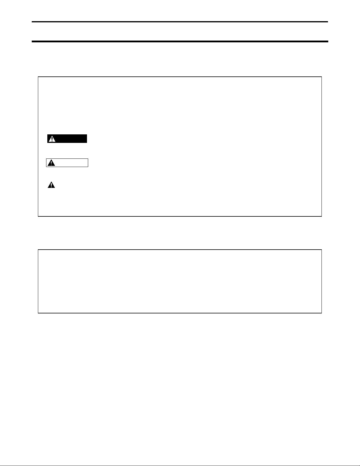
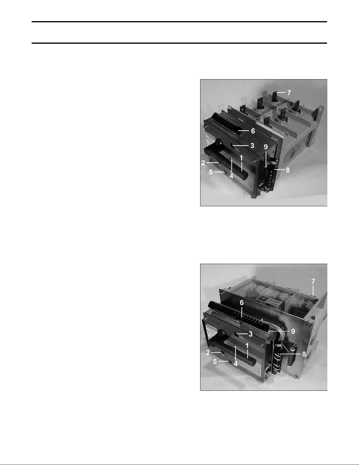
Fig. 1 U and MU Type Circuit Breaker (Upper
Arc interruption is accomplished inside sealed
vacuum interrupters mounted on track-resistant
insulators. Vacuum interrupters use low-surge
contact materials which exhibit low current
chopping levels reducing switching overvoltages.
Main Circuit Terminals)
Fig. 1 and Fig. 2 illustrate and identify the major
components of the circuit breakers.
COMPONENTS LEGEND:
1) Manual closing handle
2) Manual trip lever
3) On-Off indicator
4) Spring charge indicator (MU and ML only)
5) Operations counter
6) Secondary control circuit terminal block
7) Main circuit terminals
8) Auxiliary switch
9) Grounding terminal
Fig. 2 L and ML Type Circuit Breaker (Rear
Main Circuit Terminals)
Page 12
Page 8 GENERAL DESCRIPTION
5) Operations Counter - Indicates the total
SAFETY DEVICES
Safety interlocks and guards are provided as an
integral part of the equipment design. These
devices are provided for safety to the operator.
accumulated number of times the circuit
breaker has been closed.
DANGER
WARNING
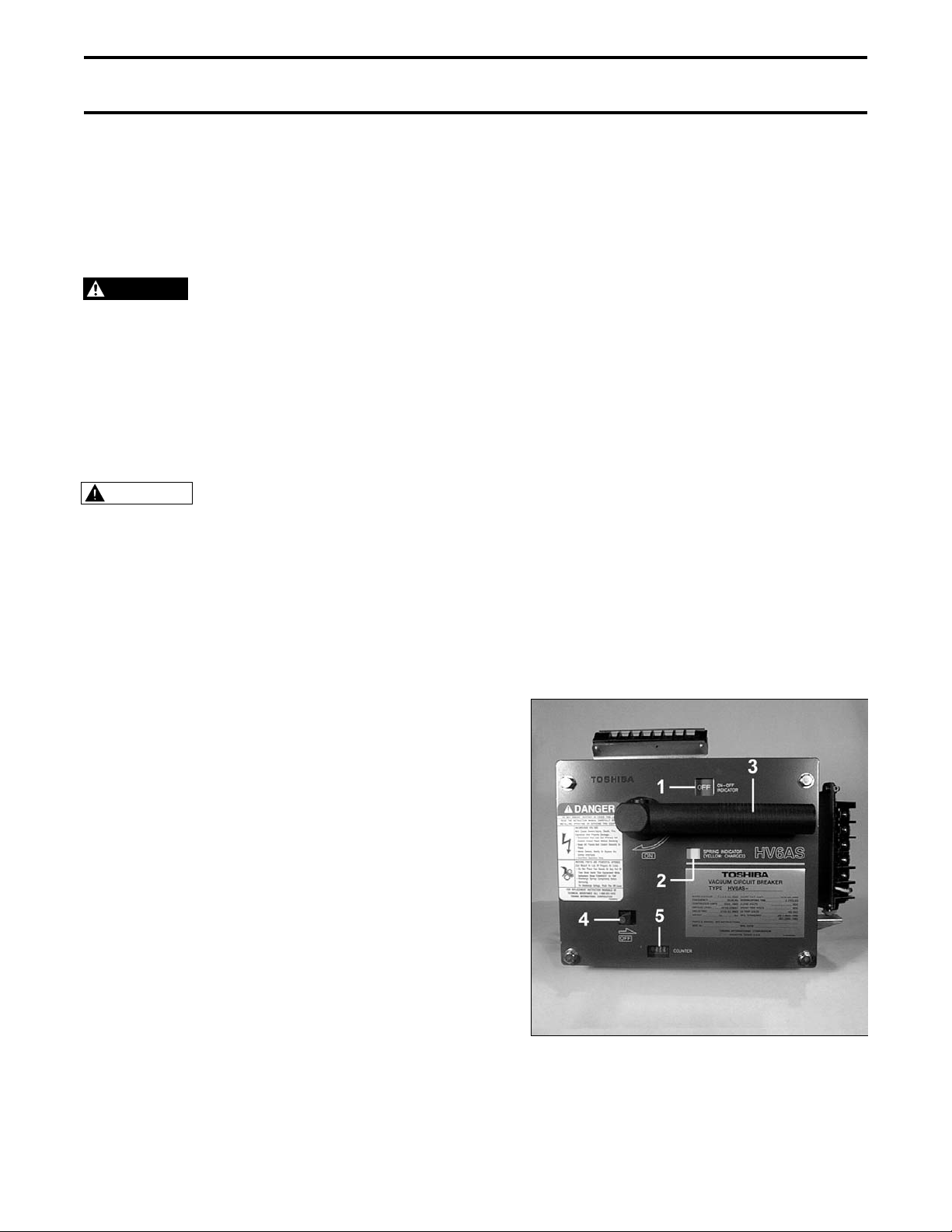
INDICATORS AND CONTROLS (Fig. 3)
The following front panel indicators and controls
are provided:
1) On-Off Indicator - Indicates if the circuit
breaker is OFF (Green) or ON (Red). When
the indicator reads OFF, the main contacts of
the circuit breaker are open. When the
indication is ON, the main contacts are
closed.
2) Closing Spring Status Indicator (MU, ML
types only) - Indicates if the closing springs
are CHARGED (Yellow) or DISCHARGED
(White).
3) Manual Closing Handle – Rotating the
handle clockwise approximately 75° closes
the circuit breaker (On-Off indicator changes
to ON). When the handle is released, it
returns to its normal position.
4) Manual Trip Lever (Red) – Pushing the lever
in the direction of the arrow trips the circuit
breaker (On-Off indicator changes to OFF).
Never defeat, modify or
bypass any safety devices,
interlocks or operating
mechanism. This would
make the equipment
unsafe. Fire, explosion,
severe injury, death and
property damage could
occur.
Do not operate this
equipment unless all
covers and panels are in
place.
Fig. 3 Indicators and Controls
Page 13

RECEIVING, INSPECTION AND HANDLING Page 9
RECEIVING AND UNPACKING
The circuit breaker units are subjected to factory
production testing prior to being packed and
shipped.
ACCEPTANCE INSPECTION
Confirm that the circuit breaker unit is complete,
correct as specified and undamaged from
shipment and handling.
Upon receipt of the equipment, do the following:
1) Make an immediate inspection for damage
which might have occurred during shipment.
If damage is discovered, it should be noted
with the carrier prior to accepting the
shipment, if possible.
2) Carefully unpack the equipment sufficiently to
check for missing parts or concealed
damage.
3) Check for the presence of accessories that
are shipped with the circuit breaker:
- Closing Handle (shipped loose with
MU and ML type breakers) (Fig. 4)
- Insulating cylinders (qty-6) (Fig. 5)
Fig. 4 Closing Handle
Fig. 5 Insulating Cylinder
3) Keep the circuit breaker upright.
Never lay the circuit
CAUTION
4) File a claim with the carrier for any damaged
or missing items and immediately notify the
nearest Toshiba representative.
WARNING
breaker on its side or
upside down. This may
cause damage.
Do not install or energize
equipment that has been
damaged. Damaged
equipment can fail during
operation, resulting in fire
and explosion.
Page 14

Page 10 RECEIVING, INSPECTION AND HANDLING
HANDLING AND MOVING
When handling and moving the circuit breaker,
the techniques shown in this section may be
used.
Care and caution should be used when handling
the circuit breaker units to avoid damage to the
equipment and personal injury. Always keep the
circuit breaker in a generally upright position.
Refer to Fig. 6 and Fig. 7 for the correct
methods of lifting and moving the circuit
breakers.
.
Fig. 6 Correct Method for Handling the U and
MU Type Circuit Breakers
Fig. 7 Correct Method for Handling the L and
ML Type Circuit Breakers
Page 15
INSTALLATION Page 11
WARNING
Do not install this
equipment in areas where
unusual service conditions
exist. Using this equipment
in other than usual service
conditions can result in
equipment failure.
Toshiba HV6AS circuit breakers are intended for
use in usual service conditions as defined in
IEEE C37.20.2. The temperature of the cooling
air (ambient air temperature) surrounding the
breaker should be between the limits of -5°C
(23°F) and +40°C (104°F). The altitude of the
equipment installation should not exceed 3300 ft
(1000 m).
In particular, avoid the following installation
conditions:
- Excessive dust
- Corrosive gases
- Extreme variations in temperature
- Very high or low humidity
- Vibrations
- Inclined locations
If there is a chance that condensation can occur
at the installation location, a space heater should
be installed inside the circuit breaker enclosure.
NOTE: Temperature, altitude or other
conditions outside of the usual limits
may require derating or other special
equipment. Contact your nearest
Toshiba representative for additional
information.
RATING VERIFICATION
Prior to Installation, the maximum fault current
capacity of the power system at the point of
installation should be verified. This value must
not exceed the symmetrical interrupting
capability of the circuit breaker. Fig. 8
illustrates a typical circuit breaker nameplate.
Do not exceed the ratings
DANGER
specified on the circuit
breaker nameplate or
system accessories.
Underrated equipment can
fail during operation
causing fire, explosion,
severe injury, death, and
property damage.
Fig. 8 Typical Circuit Breaker Nameplate
VACUUM CIRCUIT BREAKER
TYPE
RATED VOLTAGE
FREQUENCY
CONTINUOUS AMPS
IMPULSE LEVEL
DIELECTRIC
WEIGHT
PARTS & WIRING, SEE INSTRUCTIONS
SER. No.
98700221 7/98
7.2/4.8 kV, RMS
24 53
HV6AS-
50/60 Hz
630A, RMS
60 kV, CREST
22 kV AC RMS
kg
TOSHIBA INTERNATIONAL CORPORATION
TOSHIBA
MU-VV
SHORT CKT. AMPS
INTERRUPTING TIME
CLOSE VOLTS
SHUNT TRIP VOLTS
UV TRIP VOLTS
MFG. STANDARD
lbs
GF07Z301
MFG. DATE
HOUSTON, TEXAS U.S.A.
14/16 kA, RMS
3 CYCLES
120 VAC / 125
JIS C 4603-1990
JEC-2300-1985
VDC
125
VDC
120 VAC
Page 16

Page 12 INSTALLATION
MOUNTING THE CIRCUIT BREAKER TO A
PANEL
The circuit breakers are designed to mount to a
panel made from 11 ga. (.12 in.) thick steel. If
the breaker must be mounted to a panel of
different thickness, contact Toshiba.
Panel cutout dimensions for the circuit breakers
are given in Fig. 12. One cutout size is used for
all breaker types.
To mount the circuit breaker, follow the steps
below:
1. Loosen the small screw (M5) on the closing
handle and remove the handle.
2. Remove the four front plate mounting bolts
(M8) from the circuit breaker (Fig. 9).
Remove the spacer washers between the
front plate and breaker and discard them
(make sure none are left inside the breaker),
Fig. 10 Align Breaker With Panel Cutout
Fig. 11 Fasten Breaker and Front Plate to
3. Align the breaker with the cutout and
mounting holes on the panel to which it is to
be mounted (Fig. 10). Some breakers are
furnished with two hooks which may be used
to temporarily attach the breaker to the
panel.
4. Using the four M8 bolts removed in step 2,
fasten the breaker and its front plate to the
mounting panel (Fig. 11). The tightening
torque should be 120-150 kgf-cm (9-11 ft-lb).
5. Replace the closing handle removed in step
1 and the M5 screw. The screw should be
tightened to a torque of 40-50 kgf-cm (35-43
in-lb).
Panel
Fig. 9 Remove Front Plate and Spacer
Washers
Page 17

INSTALLATION Page 13
0.343 DIA
4 PLACES
8.03
0.25
10.71
0.38 RADIUS
4 PLACES
0.25
0.25
0.25
Dimensions in Inches
Fig. 12 Panel Cutout Dimensions
Page 18

Page 14 INSTALLATION
MOUNTING DIRECTLY TO A SHELF
The shelf should be flat and level within ± 0.5
mm (± 0.02 in.). If there are any noticeable gaps
between the breaker and the shelf, fill them in
using flat washers as spacers.
Check to make sure the breaker On-Off indicator
shows OFF (green), then mount it by following
the steps below:
1. Fasten the breaker onto steel angles or to a
flat plate (Fig. 13). Use M8 hex head bolts
(either 50 mm or 35 mm). The tightening
torque should be 120-150 kgf-cm (9-11 ft-lb).
2. Either mounting method shown in (Fig. 14)
may be used.
Fig. 13 Mounting Breaker to Flat Plate or
Angles
PANEL
ANGLE
M8 x 35MM OR M8 x 50MM BOLT
Fig. 14 Optional Hardware Orientation
Page 19

INSTALLATION Page 15
Fig. 15 Pass Cable Through Insulating
MAIN CIRCUIT CABLE CONNECTIONS
Cables which connect to the circuit breaker
should be routed to avoid interference with sharp
edges and moving parts. Minimum bending
radius for the type of cable used should be
observed.
Power cables should be braced and/or laced to
withstand short-circuit forces wherever such
cables are unsupported. Power cables should
be adequately sized to carry the maximum
continuous current in accordance with NEC
requirements and should have an adequate
voltage rating. Cables should be dressed and
terminated as appropriate to the voltage class
and cable manufacturer’s recommendations.
When terminating shielded cables, use
termination kits appropriate for the system
voltage to taper the insulation and reduce
electrical stress. Follow the manufacturer’s
installation instructions provided with the
termination kit.
Cylinder
Fig. 16 Fasten Cable to Main Circuit
To connect cables, follow the steps below:
1. Pass the cable through the insulating
cylinder (six cylinders are supplied with the
circuit breaker) (Fig. 15).
2. Fasten the cable to the main circuit terminal
(Fig. 16). Use 35 mm Class 8.8 M10 or M12
hex head bolts, 2 flat washers, a lock
washer and a nut. While securely preventing
the bolt from rotating with a wrench, torque
the nut to 250-315 kgf-cm (18-23 ft-lb) for
M10 bolts or 450-565 kgf-cm (32-41 ft-lb) for
M12 bolts.
Use two wrenches to torque
CAUTION
3. Fasten the insulating cylinder in place, then
check to make sure that the hook is engaged
(Fig. 17).
the connection to prevent
applying excessive force to
the terminal which can
damage the frame.
Terminal
Fig. 17 Fasten Insulating Cylinder
Page 20

Page 16 INSTALLATION
GROUND CONNECTIONS
The circuit breaker must be grounded in accordance with the requirements of the National Electrical Code, Article 250 or applicable local standards.
WARNING
It is very important that the circuit breaker and its
enclosure be adequately grounded to protect the
operator from injury in the event of short circuits
or other abnormal occurences and to ensure that
the metal parts of the equipment, other than live
parts, remain at ground potential.
For U and MU type circuit breakers, the ground
terminal is on the left side of the operating
mechanism as viewed from the rear of the
breaker. To make the ground connection, first
remove the fastening M6 hex head bolt and
crimp-on terminal (provided with the breaker)
and crimp the terminal to the end of the ground
wire (Fig. 18). Then, reattach the terminal using
the same bolt previously removed and torque to
50-65 kgf-cm (43-56 in-lb).
Proper grounding connections must be made to the circuit breaker before incoming power is applied.
Fig. 18 Ground Connection for U and MU
Type Breakers
Fig. 19 Ground Connection for L and ML
Type Breakers
For L and ML type circuit breakers, the ground
terminal is on the left side of the terminal block
as viewed from the rear of the breaker (Fig. 19).
The same instructions as for the U and MU
breaker above should be followed to attach the
ground wire.
Page 21

INSTALLATION Page 17
Fig. 20 Connection to Control Terminal
CONTROL CIRCUIT CONNECTIONS
Control circuit wiring is connected to the terminal
block on the top of the operating mechanism
(Fig. 20). Connect control wires in accordance
with the appropriate wiring diagram shown in Fig.
28 through Fig. 31 in the OPERATION section of
this manual.
On the U and MU type breakers, connections to
auxiliary contacts are made directly to the
auxiliary switch (Fig. 21).
On the L and ML type breakers, connections to
auxiliary contacts are made to a terminal block
on top of the operating mechanism (Fig. 22).
ADDITIONAL AUXILIARY SWITCH (Optional)
An optional second auxiliary switch may be
furnished, located on the right side as viewed
from the rear of the breaker.
Block
Fig. 21 Auxiliary Contact Connections on U
When a second auxiliary switch is furnished,
control wires are connected directly to the
switch.
and MU Type Breakers
Fig. 22 Auxiliary Contact Connections on L
and ML Type Breakers
Page 22

Page 18 PRE-ENERGIZATION CHECK
ELECTRICAL CHECKS
GENERAL
Electrical shock hazard.
BEFORE ENERGIZING THE CIRCUIT
BREAKER for the first time, follow the procedure
below to verify that the equipment is properly
installed and functional.
DANGER
Hazardous Voltage. Turn off
and lock out all primary and
control circuit power
sources prior to performing
this pre-energization check.
WARNING
An electrical insulation resistance test should
be performed to verify that the circuit breaker
and associated field wiring are free from
short circuits and grounds. Refer to the
MAINTENANCE Section of this manual for
additional information.
Do not touch energized
components during a test
using auxiliary power.
WARNING
WARNING
WARNING
WARNING
All blocks or other temporary braces used for
shipment must be removed.
Before closing the enclosure, all metal chips,
scrap wire and other debris left over from
installation must be cleaned out.
Do not operate this
equipment until a complete
safety inspection has been
made.
Do not energize damaged
equipment that has not
been repaired or verified.
Do not remove, cover or
destroy any safety signs.
Do not operate this
equipment until all panels
and covers have been
installed.
Hazardous voltages are
WARNING
The circuit breaker must be set to the OFF
position before energizing incoming power.
present during dielectric
testing which can result in
serious injury or death.
High potential tests should
be performed only by
qualified personnel.
Cover all unused openings. Install all panels,
guards and covers.
A supply of spare parts should be
established.
Instruction manuals and diagrams should be
collected and filed.
Page 23

OPERATION Page 19
MANUAL OPERATION
WARNING
CAUTION
MANUAL CLOSING (Motor-Operated MU and
ML Types):
1. Check to make sure that the On-Off
indicator shows OFF (green).
2. Attach the closing handle to the breaker if it
is not already attached.
3. If the closing spring status indicator shows
DISCHARGED (white):
Powerful springs. Do not
place your hands or any
part of your body inside
the circuit breaker while
the indicators show
CHARGED (yellow) or ON
(red).
To avoid damaging the
mechanism, do not close
the circuit breaker when
the On-Off Indicator shows
ON (red).
Fig. 23 Preparing to Manually Close Breaker
Fig. 24 Manually Closing Breaker
Turn the closing handle clockwise (Fig. 23).
The breaker will close (On-Off indicator
changes to ON) after the handle is turned
approximately 75° (Fig. 24).
NOTE If the handle is turned in small
increments, the closing spring will
store the energy from the handle
action and the circuit breaker will
close before 75° of rotation.
If the closing spring status indicator shows
CHARGED (yellow):
Turn the closing handle clockwise. The
breaker will close after the handle is turned
approximately 10°.
4. Release the handle, and it will return to its
initial position.
Page 24

Page 20 OPERATION
Fig. 25 Manually Opening Breaker
MANUAL CLOSING (Manual Spring-Operated
U and L Types):
1. Check to make sure that the On-Off
indicator shows OFF (green).
2. Turn the closing handle clockwise. The
breaker will close (On-Off indicator changes
to ON) after the handle is turned
approximately 75°.
NOTE If the handle is turned in small
increments, the closing spring will
store the energy from the handle
action and the circuit breaker will
close before 75° of rotation.
3. Release the handle, and it will return to its
initial position.
SYMBOL DESCRIPTION
MANUAL OPENING (All Types):
1. Push the trip lever in the direction of the
arrow (Fig. 25).
2. The On-Off indicator changes to OFF
(green).
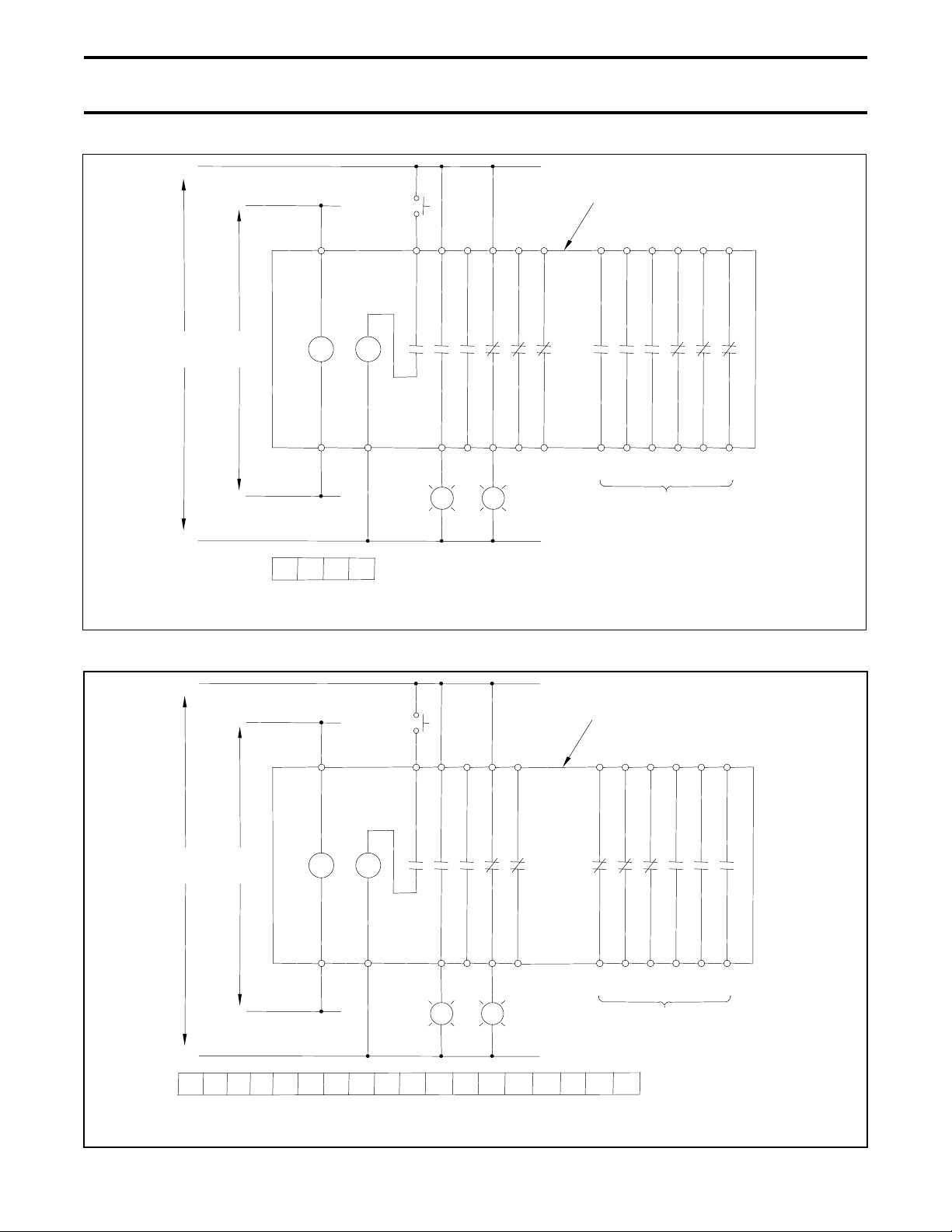
ELECTRICAL OPERATION
The flow chart shown in Fig. 27 illustrates the
sequence of electrical operation of the MU and
ML type circuit breakers.
Refer to Fig. 26 and the circuit breaker
schematics shown in Fig. 28 through Fig. 31 for
determining external control circuit connections
to the circuit breaker.
M Motor
TC Voltage Trip Coil
UV Undervoltage Trip Coil
a1 to a6 Auxiliary Contacts (N.O.)
b1 to b6 Auxiliary Contacts (N.C.)
X Control Relay
X-a Control Relay Contact (N.O.)
X-b Control Relay Contact (N.C.)
Y Auxiliary Relay
Y-a Auxiliary Relay Contact (N.O.)
Y-b Auxiliary Relay Contact (N.C.)
LS1 to LS3 Limit Switches
R1 to R4 Resistors
REC Rectifier
D Diode
C Capacitor
SP Surge Protector
RL Red Lamp
GL Green Lamp
Fig. 26 Legend for Schematics
Page 25

OPERATION Page 21
Circuit Breaker Open
Control Power Applied
Motor Begins Operating
Closing Springs Begin Charging
Closing Springs Charged
Motor Stops
Closing Signal Given
Motor Begins Operating
Circuit Breaker Closes
Auxiliary Relay Closes
Anti-Pumping Circuit Completed
Opening Signal Given
- - - - Spring Status Indicator Changes to Yellow
- - - - Standby for Close Operation
- - - - Spring Status Indicator Changes to White
and On-Off Status Changes to ON
- - - - Next Close Operation is Not Possible
Unless Close Signal is Canceled
Trip Coil Energized
Circuit Breaker Opens
Fig. 27 Electrical Operation Flow Chart for MU
and ML Type Breakers
- - - - On-Off Status Indicator Changes to OFF
Page 26
Page 22 OPERATION
(
)
(
)
+
OFF
C4 K 1514 1312 11 16 15 14 13 12 11
Circuit Breaker Components
Shown Inside Box
125 VDC
SUPPLY
-
120 VAC
SUPPLY
TCUV
C04 N2
C04C4N2K
Terminal Layout
As Viewed From Front of Circuit Breaker
a3 a2 a1 b3 b2 b1 a6 b5a4a5 b6 b4
25 24 23 22 21 26 2425 2223 21
RL GL
Fig. 28 125 VDC Control Circuit Schematic for U Type Circuit Breaker
Fig. 29 125 VDC Control Circuit Schematic for L Type Circuit Breaker
+
OFF
C4 K
A2 A1 B2 B1
Optional Auxiliary Contacts
Circuit Breaker Components
Shown Inside Box
16 15 14 13 12 11
125 VDC
SUPPLY
120 VAC
SUPPLY
-
Terminal La yout
As Viewed From Front of Circuit Breaker
TCUV
C04 N2
C04C4N2K
a3 a2 a1 b2 b1 b6 a5b4b5 a6 a4
A02 A01 B02 B01
RL GL
A01A1 A2 A02 B1 B01
26 2425 2223 21
Optional Auxiliary Contacts
B2 B02
Page 27

OPERATION Page 23
Y
YR3Y-aY
Fig. 30 125 VDC Control Circuit Schematic for MU Type Circuit Breaker
+
Fig. 31 125 VDC Control Circuit Schematic for ML Type Circuit Breaker
ON
OFF
Circuit Breaker Components
Shown Inside Box
125 VDC
SUPPLY
-
120 VAC
SUPPLY
C4 K 1514 131211 161514131211
C04 N2
PR3
SP
REC
X-a
LS2
M
LS3 LS3
NT3
Components Inside Dashed Box Located
On Control Circuit Board
Terminal Layout
(As Viewed From Front of Circuit Breaker)
X-a
X-b
R1 X-a
HPR3 NT3
H
D
-b
-bCR4
R2
X
C04C4N2K
a3 a2 a1 b3 b2 b1 a6 b5a4a5 b6 b4
LS1
TCUV
25 24 23 22 21 26 2425 2223 21
RL GL
Optional Auxiliary Contacts
(Connect Wires Directly To
Auxiliary Switch Terminals)
+
125 VDC
SUPPLY
-
120 VAC
SUPPLY
ON
C4 K A2A1 B2B1 161514131211
NT3
C04 N2
PR3
SP
REC
X-a
LS2
M
LS3 LS3
Components Inside Dashed Box Located
On Control Circuit Board
Terminal Layout
(As Viewed From Front of Circuit Breaker)
X-a
X-b
X-a
R1
HPR3 NT3
H
D
Y-b
R2
X Y
Y-a
Y-bCR4
R3
OFF
a3 a2 a1 b2 b1 b6 a5b4b5 a6 a4
LS1
TCUV
A02 A01 B02 B01 26 2425 2223 21
RL GL
A1
C04C4N2K
A01
A2 B1
A02 B01
Circuit Breaker Components
Shown Inside Box
Optional Auxiliary Contacts
(Connect Wires Directly To
Auxiliary Switch Terminals)
B2
B02
Page 28

Page 24 OPERATION
UNDERVOLTAGE TRIP
All HV6AS fixed mounted circuit breakers are
furnished with an undervoltage trip device. The
undervoltage trip device operates to trip the
circuit breaker OFF unless 120VAC control
power is present at the terminals of relay UV.
When the circuit breakers are shipped, the
undervoltage trip device is defeated by a factoryinstalled plug (Fig. 32). If this plug is left in
place, the circuit breaker will operate normally
without power applied to relay UV. Removing
this plug (Fig. 33) activates the undervoltage trip
function.
Fig. 33 Removing Plug From UV Trip Device
Fig. 32 Plug Installed in UV Trip Device
Page 29
MAINTENANCE Page 25
6) Comments
MAINTENANCE PROGRAM
The degree of detail of the record will depend
In order to ensure continued reliable and safe
operation of the equipment, a program of
periodic maintenance must be established.
Operating and environmental conditions will
usually dictate the frequency of inspection
required. NFPA Publication 70B "Electrical
Equipment Maintenance" may be used as a
guide for setting up the maintenance program.
somewhat on the operating conditions.
SERVICING EQUIPMENT
For your safety, turn off and lock out main and
control circuit power before servicing the circuit
breaker. Certain minimum safety procedures
must be followed:
DANGER
WARNING
WARNING
Contact with energized
components can cause
severe injury, death and
property damage. Turn off
and lock-out primary and
control circuit power before
servicing.
Improper maintenance can
cause severe injury, death
and property damage. Only
qualified and authorized
persons are to install,
operate or service this
equipment.
Grease is conductive. Do
not allow grease or any
other substances to
contaminate insulating
materials. Contaminated
insulators can allow a
short-circuit or ground
fault to occur.
1) Only qualified personnel should attempt
this service.
2) Never perform service on or next to
exposed components energized with line
voltage.
Failure to adhere to these
safety procedures can
WARNING
result in severe injury,
death and property
damage.
NOTE: Refer to the SAFETY section of this
manual for important information.
MAINTENANCE RECORD
Keep a permanent record of all maintenance
work. At a minimum, this record should include
information on:
1) Items inspected
2) Reports of any testing
3) Equipment condition
4) Corrective actions or adjustments
5) Date of work
Page 30

Page 26 MAINTENANCE
RECOMMENDED INSPECTION AND
MAINTENANCE TYPES
NOTE: Refer to the SAFETY section of this
manual for important information.
A. Acceptance Inspection
This inspection confirms that the circuit
breaker unit is complete, correct as specified,
and undamaged from shipment. The
procedure for this inspection is outlined in the
RECEIVING, INSPECTION AND HANDLING
section of this manual.
B. Patrol Inspection
Inspection is made of the condition of the
circuit breaker while it is energized. Check
that no unusual sounds or smells exist
externally.
Inspection Frequency: Once every 6 months
C. Periodic Inspection
Screw
Nominal
Dia.
M4 15-20 kgf-cm
13-17 in-lb
M5 30-40 kgf-cm ()
26-34 in-lb
M6 50-65 kgf-cm ()
43-56 in-lb
M8 120-150 kgf-cm ()
9-11 ft-lb
M10 250-315 kgf-cm ()
18-23 ft-lb
M12 450-565 kgf-cm ()
32-41 ft-lb
Tightening Torque
Inspection is performed wth the circuit
breaker de-energized. The lubrication of
sliding and rotating parts is checked and the
mechanism is lubricated if needed.
Inspection Frequency: Once every 1-3 years
or every 3000 operations (normal). Once
every 6 years (detailed).
Refer to Table 2 for the schedule of Periodic
Inspections.
D. Unscheduled Inspection
Inspections are implemented as required.
Inspection Frequency: As needed
NOTE: The inspection frequency and points
to be inspected may vary from the
above recommendations depending
on the status of use, frequency of
switching, amount of current
interrupted and other factors.
Table 1 Tightening Torques
Page 31
MAINTENANCE Page 27
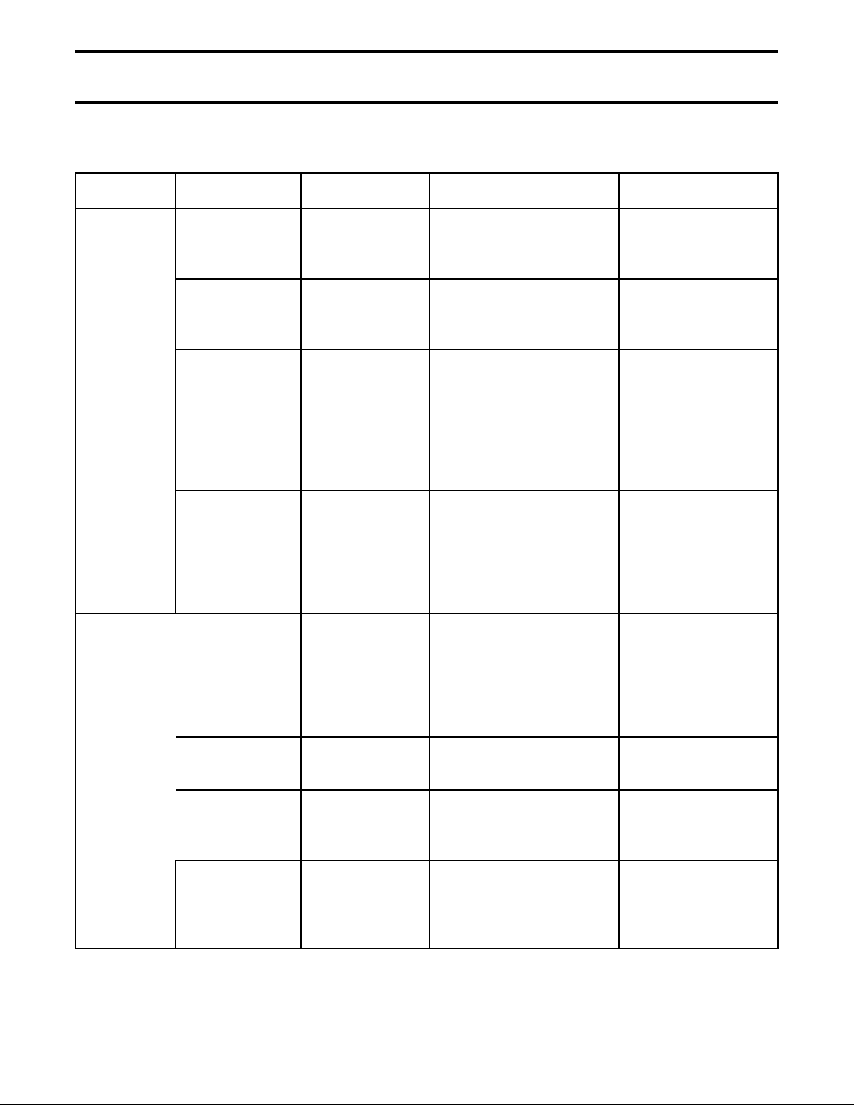
Table 2 Check Points for Periodic Inspection
Check Point Check Item Check Method Criteria Disposition
Operating
Mechanism
Loose bolts,
nuts or screws
Dust or foreign
matter inside
Indicator
operation
Warpage Visual
Smooth
operation
Tighten using
screwdriver or
wrench.
Visual
inspection.
Visual
inspection.
inspection.
Manual
operation.
Visual
inspection or
touch. Check
lubrication.
Make sure all bolts, nuts
and screws are tight.
The circuit breaker
should be clean and
contain no foreign matter.
Make sure the number of
operations is correctly
displayed.
There should be no
warpage or missing
parts.
Make sure moving parts
operate smoothly.
Tighten if loose.
See Table 1 for
tightening torques.
Wipe with a clean
dry cloth.
Check the cause
and repair.
Check the cause
and repair.
Apply a small
amount of
lubrication.
Main Circuit Discoloration
due to heat
from conducting
parts
Loose bolts,
nuts or screws
Dust on surface
of vacuum
interrupter
Insulator Dust, foreign
matter or
damage
Visual
inspection.
Tighten using a
wrench.
Visual
inspection.
Visual
inspection.
Make sure there is no
discoloration.
Make sure all bolts, nuts
and screws are tight.
Make sure there is no
dust on the surface.
Make sure there is no
dust, foreign matter or
breakage.
Check the cause
and repair. Tighten
connections to circuit
breaker. See Table
1 for tightening
torques.
See Table 1 for
tightening torques.
Wipe with a clean,
dry cloth.
Wipe with a clean,
dry cloth. If
damaged, contact
Toshiba.
Page 32

Page 28 MAINTENANCE
Table 2. Check Points for Inspection (cont’d)
Check Point Check Item Check Method Criteria What to do
Auxiliary
Switch
Control
Circuits
Insulation
Resistance
Measurement
Terminals loose
or disconnected
Case/contacts Visual
Smooth
movement of
motor charging
mechanism
Terminals loose
or disconnected
Meaure main
circuit to ground
Meaure
between main
circuit terminals
Visual
inspection.
Tighten using a
screwdriver.
inspection.
Energize the
control circuit.
Visual
inspection.
Tighten using a
screwdriver.
Megger test at
1000V.
Megger test at
1000V.
Make sure terminals are
not loose or disconnected.
Make sure there is no
damage or warping.
Breaker (motor-operated
type) should charge
quickly and smoothly.
Make sure terminals are
not loose or disconnected.
Resistance should be
500MΩ or greater.
Resistance should be
100MΩ or greater.
Repair if
disconnected.
Tighten if loose.
See Table 1 for
tightening torques.
Replace if damaged
or warped.
If the circuit fails to
operate, check the
cause and repair.
Repair if
disconnected.
Tighten if loose.
See Table 1 for
tightening torques.
If the insulation
resistance is low,
wipe off the vacuum
interrupter and other
insulation surfaces
with a clean dry
cloth and then
repeat the test.
Meaure control
circuits to
ground
Megger test at
500V.
Resistance should be
2MΩ or greater.
Page 33

MAINTENANCE Page 29
Hazardous voltages are
VACUUM CHECK
A sufficient level of vacuum is necessary for
proper performance of the vacuum interrupters.
Although vacuum leaks are rare, the vacuum
integrity should be checked periodically. The
relationship between dielectric breakdown
voltage of the contact gap and internal vacuum
interrupter pressure has been found to be
generally predictable. Therefore, vacuum
interrupter integrity is checked by performing a
high potential test across the open gap of the
interrupter.
TEST EQUIPMENT:
Toshiba offers a compact vacuum checker (Type
CI35-1D) which enables a quick and easy check
on vacuum interrupter internal pressure.
Alternatively, any commercially available AC high
potential tester may be used which is capable of
delivering at least 25 milliamperes at 22 kV for a
period of one minute.
PRECAUTIONS:
Applying abnormally high voltage across a pair of
contacts in vacuum may produce X-rays. The
radiation may increase with the increase in
voltage and/or decrease in contact spacing. Xradiation produced during this test with
recommended voltage and normal contact
spacing is extremely low and well below the
maximum permitted by standards. As an
additional safety measure, however, it is
recommended that all personnel keep at least 1
meter (3.3 ft) away from the vacuum circuit
breaker while this test is performed.
WARNING
TEST PROCEDURE:
1. The circuit breaker should be disconnected
from the main circuit and be in the OFF
position.
2. Connect all the line side primary terminals
together and to the output of the vacuum
checker or AC hi-pot machine. Connect all
the load side primary terminals together and
to the ground terminal of the vacuum checker
or AC hi-pot machine.
3. Increase the voltage from zero to 22kV AC at
a rate of approximately 2kV per second.
Hold the voltage at this value for 1 minute
and observe the current drawn by the
interrupter.
4. Decrease the voltage back to zero.
Fig. 34 Toshiba Portable Vacuum Checker
present during dielectric
testing which can result in
severe injury or death.
Only qualified personnel
should conduct this testing.
WARNING
Radiation exposure hazard.
X-rays may cause illness or
injury. Stay at least 1 meter
(3.3 ft) away from the circuit
breaker during the vacuum
check test .
Page 34

Page 30 MAINTENANCE
CRITERIA:
Fig. 35 Application of Test Voltage for
1. If a current flow above 5 milliamperes is
observed or if breakdown occurs, one or
more of the interrupters has insufficient
vacuum and must be replaced.
Exception: If the current exceeds 5
milliamperes the first time the voltage is
brought up, reduce the voltage to zero and
increase it again. It may be necessary to
repeat this procedure a few times.
2. If the breaker fails to meet criteria 1, then
repeat the test on each pole separately to
identify the damaged interrupter or
interrupters.
3. If the voltage can be held for 1 minute and
the current flow does not exceed 5
milliamperes, the interrupter has a sufficient
vacuum level.
Vacuum Check
1 minute
22kV AC
(31kV DC)
Voltage
Zero
15 sec 15 sec
Time
After the test is complete, discharge any residual
static charge from the primary terminals of the
circuit breaker.
If a vacuum checker or AC hi-pot tester is not
available, a DC hi potential test may be
conducted. If a DC test is conducted, the test
voltage must be increased to 31kV DC. The test
duration for DC tests and the criteria for
acceptance remain the same as for AC tests.
Do not use DC hi-pot
WARNING
testers which employ
unfiltered half-wave
rectifiers. The peak
voltages produced by these
testers may exceed the
recommended value of
31kV. This can result in the
production of harmful Xrays and may invalidate the
test results.
Page 35

DISPOSAL Page 31
DISPOSAL
Contact your state environmental agency for
details on disposal of electrical components and
packaging in your particular area.
Page 36

STORAGE Page 32
STORAGE
If the circuit breaker is to be stored for any length
of time prior to installation, the following
precautions should be taken:
1) The original packing should be restored, if
possible.
2) Do not subject the equipment to moisture or
sun rays. Store in cool, clean, and dry
location.
3) Place a dust cover over the circuit breaker
packaging to protect against dirt and
moisture.
4) Store in an upright position.
INSPECTION DURING STORAGE
Routine scheduled inspection is necessary if
storage is for an extended period. The unit
should be checked for condensation, moisture,
corrosion, and vermin.
Prior to installation, the circuit breaker should be
carefully examined for evidence of physical
damage, corrosion, or other deterioration. Refer
to the PRE-ENERGIZATION Section of this
manual.
The MAINTENANCE section of this manual
describes various types of inspections
recommended for this circuit breaker during the
operation period.
Page 37

SPECIFICATIONS Page 33
Table 3 Circuit Breaker Ratings – Manual Operation HV6AS-U and HV6AS-L Types
Rated Voltage kV, rms 7.2 4.8
Rated Low Frequency Withstand Voltage kV, rms 22
Impulse Withstand Voltage kV, crest 60
Rated Continuous Current A, rms 630
Rated Frequency Hz 50/60
Rated Short-Circuit Breaking Current kA, rms 14 16
Rated Short-Circuit Making Current kA, crest 35 40
Rated Short-Time Withstand Current (2 sec) kA, rms 12.5
Rated Interrupting Time (60Hz Basis) cycles 3
Opening Time msec 8 - 25
Rated Control Voltage (Opening) V DC 30, 125
Rated Control Voltage (Undervoltage Trip) V AC 120
Operating Duty O - 1 min - CO - 3 min - CO
Auxiliary Contacts 2 N.O. - 2 N.C.
Weight kg 22 (U Type) 25 (L Type)
Table 4 Circuit Breaker Ratings – Motor Stored Energy Operation HV6AS-MU and HV6AS-ML
Types
Rated Voltage kV, rms 7.2 4.8
Rated Low Frequency Withstand Voltage kV, rms 22
Impulse Withstand Voltage kV, crest 60
Rated Continuous Current A, rms 630
Rated Frequency Hz 50/60
Rated Short-Circuit Breaking Current kA, rms 14 16
Rated Short-Circuit Making Current kA, crest 35 40
Rated Short-Time Withstand Current (2 sec) kA, rms 12.5
Rated Interrupting Time (60Hz Basis) cycles 3
Opening Time msec 8 - 25
Closing Time msec 150 - 300
Charging Time sec 1.5 - 3
Rated Control Voltage (Closing/Charging) V AC 120, DC 125
Rated Control Voltage (Opening) V DC 30, 125
Rated Control Voltage (Undervoltage Trip) V AC 120
Operating Duty O - 1 min - CO - 3 min - CO
Auxiliary Contacts 2 N.O. - 2 N.C.
Weight kg 24 (MU Type) 27 (ML Type)
Page 38

Page 34 WARRANTY AND LIMITATION OF LIABILITY
Toshiba International Corporation ("Company") warrants that all equipment and parts described herein will be free
from defects in materials and workmanship. THIS WARRANTY WILL EXPIRE EIGHTEEN (18) MONTHS AFTER
THE DATE ON WHICH SUCH EQUIPMENT AND PARTS (EXCLUDING REPAIRED OR REPLACEMENT
EQUIPMENT AND PARTS FURNISHED PURSUANT TO THIS WARRANTY) ARE SHIPPED BY THE COMPANY
TO THE INITIAL PURCHASER OR TWELVE (12) MONTHS AFTER SUCH EQUIPMENT AND PARTS
(EXCLUDING REPAIRED OR REPLACEMENT EQUIPMENT AND PARTS FURNISHED PURSUANT TO THIS
WARRANTY) ARE FIRST PLACED IN OPERATION, WHICHEVER PERIOD FIRST EXPIRES.
The Company will, at its option, repair or replace such equipment or part which is defective under the terms of the
foregoing warranty, free of charge; provided the purchaser (1) promptly notifies the Company in writing of such
defect, and (2) furnishes the Company satisfactory proof thereof, and (3) establishes that the equipment or part has
been properly installed, maintained and operated within the limits of rated capacity and normal usage and in
accordance with this manual, and (4) if requested by the Company, returns the defective equipment or part to the
Company and pays all expenses incurred in connection with such return. The repaired or replacement equipment or
part will be delivered, free of charge, to the purchaser F.O.B. the Company's warehouse or, at the Company's option,
F.O.B. a Company authorized service shop, not loaded on truck or other carrier. The purchaser will pay the costs
applicable to the equipment or part following such delivery, including, without limitation, all handling, transportation,
assembly, insurance, testing and inspection charges.
THE FOREGOING OBLIGATION TO REPAIR OR REPLACE EQUIPMENT PARTS SHALL BE THE SOLE AND
EXCLUSIVE REMEDY OF THE PURCHASER, ITS CUSTOMERS AND USERS OF THE EQUIPMENT AND
PARTS FOR BREACH OF THE FOREGOING WARRANTY. THE COMPANY WILL HAVE NO OBLIGATIONS TO
DISASSEMBLE ANY EQUIPMENT OR PART WHICH IS DEFECTIVE WITHIN THE TERMS OF THE ABOVE
WARRANTY OR TO INSTALL ANY REPAIRED OR REPLACEMENT PART OR EQUIPMENT OR TO PAY ANY
COSTS INCURRED IN CONNECTION WITH ANY SUCH DISASSEMBLY OR INSTALLATION. THE COMPANY,
TOSHIBA CORPORATION AND THEIR SUPPLIERS AND SUBCONTRACTORS HEREBY DISCLAIM ALL
OTHER EXPRESS, STATUTORY AND IMPLIED WARRANTIES, INCLUDING, WITHOUT LIMITATION, ALL
EQUIPMENT AND PARTS FURNISHED PURSUANT TO THE FOREGOING WARRANTY AND ALL IMPLIED
WARRANTIES OF MERCHANTABILITY.
The total liability of the Company, Toshiba Corporation and their suppliers and subcontractors for any loss, damage
or claim, whether in contact, tort (including negligence and liability without fault), or otherwise, arising out of,
connected with or resulting from the equipment and parts described in this manual or the performance or breach of
any contract for the sale or supply of such equipment and parts, or from the design, manufacture, sale, delivery,
resale, installation, technical direction or supervision of installation, inspection, testing, repair, replacement,
operation, maintenance or use of any such equipment or part or any service relating thereto furnished by the
Company shall not in any event exceed the price allocable to the equipment, part or service which gives claim, loss
or damage. In no event, whether as a breach of contract or warranty, alleged negligence, liability without fault, or
otherwise, shall the Company, Toshiba Corporation or their suppliers or subcontractors be liable for special or
consequential damages, including, without limitation, loss or profits or revenue, loss of equipment described herein
or any associated equipment, cost of capital, cost of substitute equipment or parts, facilities or services, down-time
costs, labor costs or claims of customers of the purchaser for such damages.
Page 39

TOSHIBA
TOSHIBA INTERNATIONAL CORPORATION
13131 W. Little York Road, Houston, TX 77041,
U.S.A.
Tel: (713) 466-0277Fax: (713) 466-8773
 Loading...